

Avigilon 1.0-H3M-DP1, 2.0-H3M-DP1 Installation Manual
InstallationGuide
Avigilon™ High Definition H.264 IP Micro Dome Camera Models:
1.0-H3M-DP1 and 2.0-H3M-DP1
Important Safety Information
This manual provides installation and operation information and precautions for the use of this camera. Incorrect
installation could cause an unexpected fault. Before installing this equipment read this manual carefully. Please
provide this manual to the owner of the equipment for future use.
The Warning symbol indicates the presence of dangerous voltage within and outside the product
enclosure that may constitute a risk of electric shock, serious injury or death to persons if proper
precautions are not followed.
The Caution symbol alerts the user to the presence of hazards that may cause minor or moderate injury
to persons, damage to property or damage to the product itself if proper precautions are not followed.
WARNING — Failure to observe the following instructions may result in severe injury or death.
l Installation must be performed by qualified personnel only, and must conform to all local codes.
l This product is intended to be used in an Network Environment 0 per IEC TR62101. The camera is to be
connected only to PoE network that complies with IEEE 802.3af without routing to the outside plant.
CAUTION — Failure to observe the following instructions may result in injury or damage to the camera.
l Do not install near any heat sources such as radiators, heat registers, stoves, or other sources of heat.
l Do not subject the cables to excessive stress, heavy loads or pinching.
l Do not open or disassemble the device. There are no user serviceable parts.
l Refer all servicing to qualified personnel. Servicing may be required when the device has been damaged
(such as from a liquid spill or fallen objects), has been exposed to rain or moisture, does not operate
normally, or has been dropped.
l Do not use strong or abrasive detergents when cleaning the device body.
l Use only accessories recommended by Avigilon.
Regulatory Notices
This device complies with part 15 of the FCC Rules. Operation is subject to the following two conditions: (1) This
device may not cause harmful interference, and (2) this device must accept any interference received, including
interference that may cause undesired operation.
This Class B digital apparatus complies with Canadian ICES-003.
ii
FCC Notice
This equipment has been tested and found to comply with the limits for a Class B digital device, pursuant to Part
15 of the FCC rules. These limits are designed to provide reasonable protection against harmful interference in a
residential installation. This equipment generates, uses and can radiate radio frequency energy and, if not
installed and used in accordance with the instructions, may cause harmful interference to radio communications.
However, there is no guarantee that interference will not occur in a particular installation. If this equipment does
cause harmful interference to radio or television reception, which can be determined by turning the equipment
off and on, the user is encouraged to try to correct the interference by one or more of the following measures:
l Reorient or relocate the receiving antenna.
l Increase the separation between the equipment and the receiver.
l Connect the equipment into an outlet on a circuit different from that to which the receiver is connected.
l Consult the dealer or an experienced radio/TV technician for help.
Changes or modifications made to this equipment not expressly approved by Avigilon Corporation or parties
authorized by Avigilon Corporation could void the user’s authority to operate this equipment.
Disposal and Recycling Information
When this product has reached the end of its useful life, please dispose of it according to your local
environmental laws and guidelines.
Risk of fire, explosion, and burns. Do not disassemble, crush, heat above 100 °C (212 °F), or incinerate.
European Union:
This symbol means that according to local laws and regulations your product should be disposed of separately
from household waste. When this product reaches its end of life, take it to a collection point designated by local
authorities. Some collection points accept products for free. The separate collection and recycling of your
product at the time of disposal will help conserve natural resources and ensure that it is recycled in a manner
that protects human health and the environment.
Legal Notices
© 2014 -2015 Avigilon Corporation. All rights reserved. Unless expressly granted in writing, no license is granted
with respect to any copyright, industrial design, trademark, patent or other intellectual property rights of Avigilon
Corporation or its licensors.
AVIGILON is a registered and/or unregistered trademark of Avigilon Corporation in Canada and other
jurisdictions worldwide. Other product names mentioned herein may be the unregistered and/ or registered
trademarks of their respective owners. ™ and ® are not used in association with each trademark in this document.
iii

Disclaimer
This manual has been compiled and published covering the latest product descriptions and specifications. The
contents of this manual and the specifications of this product are subject to change without notice. Avigilon
reserves the right to make changes without notice in the specifications and materials contained herein and shall
not be responsible for any damages (including consequential) caused by reliance on the materials presented,
including but not limited to typographical and other errors relating to the publication.
Avigilon Corporation
http://www.avigilon.com
920-0126A
Revision: 3 - EN
2015-01-20
iv

Table of Contents
Overview 1
Housing View 1
Front View 2
Cable Assembly 3
Installation 4
Required Tools and Materials 4
Camera Package Contents 4
Installation Steps 4
Preparing for the Installation 4
Connecting Power Over Ethernet (PoE) 7
Mounting the HD Micro Dome Camera 9
Assigning an IP Address 9
Accessing the Live VideoStream 9
Aiming the HD Micro Dome Camera 10
For More Information 12
LED Indicators 13
Resetting to Factory Default Settings 14
Setting the IP Address Using the ARP/Ping Method 15
Cleaning 16
Dome Bubble 16
Body 16
Specifications 17
Limited Warranty & Technical Support 19
v
Overview
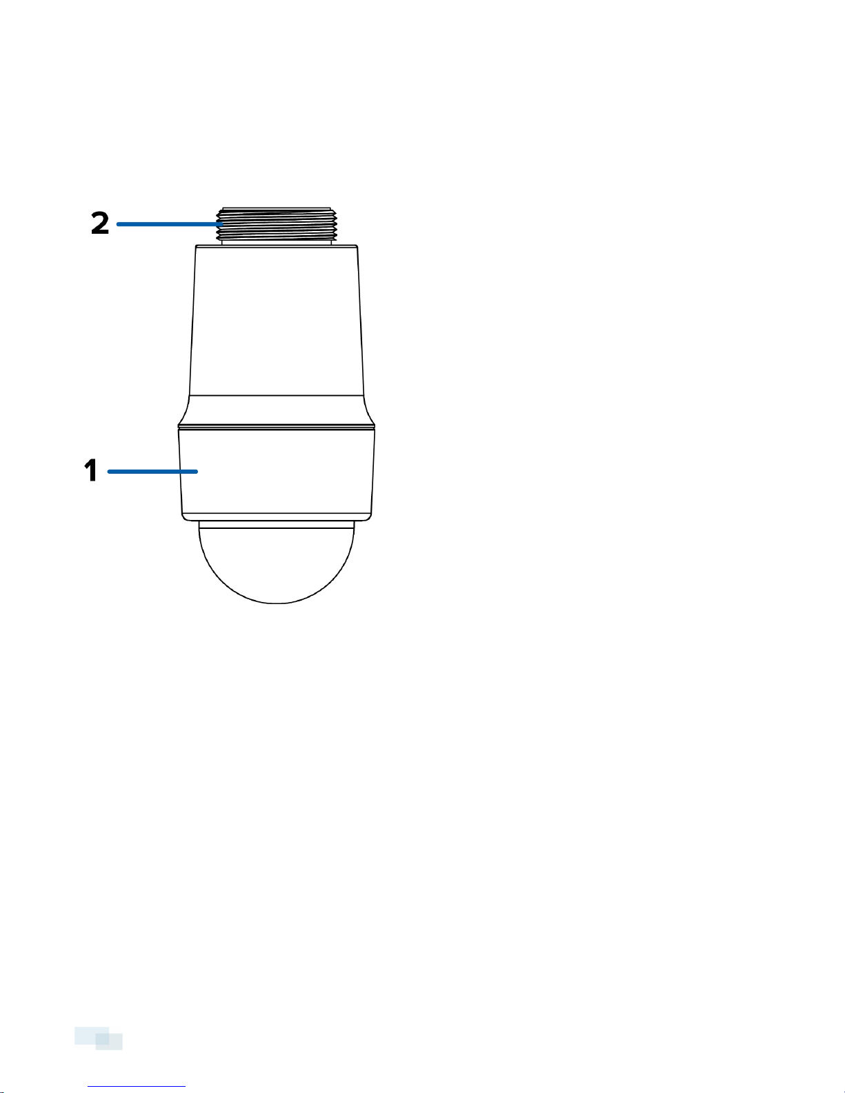
Housing View
1. Dome Cover
Attaches the camera dome bubble to the camera housing.
2. 1.5" Thread
Thread for mounting the camera onto the mounting conduit.
1 Overview
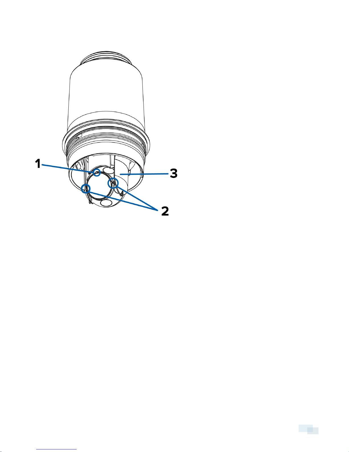
Front View
1. Vertical Marker
Provides a vertical reference point for the video image. Points up.
2. Horizon Markers
Provide reference points for aligning the video image with the horizon line.
3. Gimbal
Allows you to move and aim the camera after it has been installed.
Front View 2
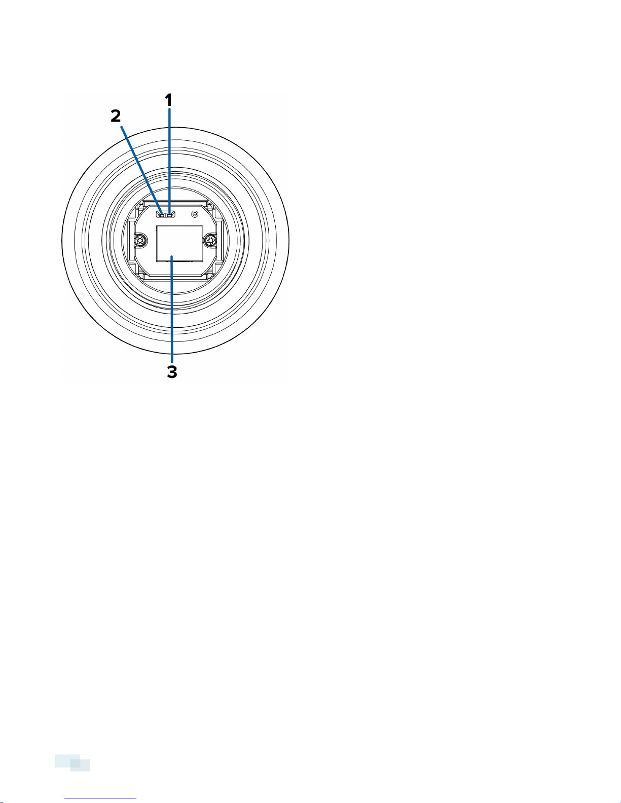
Cable Assembly
1. Link LED
Indicates if there is an active connection in the Ethernet port.
2. Connection Status LED
Provides information about device operation. For more information, see LED Indicators on page13
3. Ethernet Port
Accepts power and Ethernet connection to the network.
The camera can only be powered by Power over Ethernet (PoE). Server communication and image data
transmission also occurs over this connection.
3 Cable Assembly
 Loading...