

Avigilon 2.0-H3-D2, 1.0-H3-D2, 3.0W-H3-D1-IR, 3.0W-H3-D2, 5.0-H3-D1 Installation Manual
...
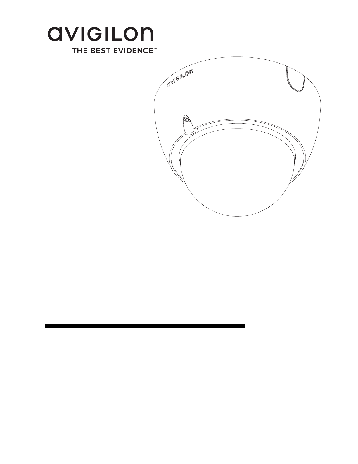
Installation Guide
Avigilon High Definition H.264 IP Dome
Camera Models:
1.0-H3-D1, 1.0-H3-D1-IR, 1.0-H3-D2, 2.0-H3-D1, 2.0-H3-D1-IR,
2.0-H3-D2, 3.0W-H3-D1, 3.0W-H3-D1-IR, 3.0W-H3-D2, 5.0-H3-D1,
5.0-H3-D1-IR and 5.0-H3-D2
920-0049C-Rev1

i
English
Important Safety Information
This manual provides installation and operation information and
precautions for the use of this dome camera. Incorrect installation
could cause an unexpected fault. Before installing this equipment read
this manual carefully. Please provide this manual to the owner of the
equipment for future use.
• Do not use near water or expose to dripping or splashing.
Do not place objects filled with liquids above the device.
• Do not expose to rain or moisture.
• For indoor use only.
If used outdoors, an approved outdoor mounting adapter
or enclosure is required. Consult with Avigilon for more
information.
• Installation must be performed by qualified personnel only,
and must conform to all local codes.
• This product is intended to be supplied by a UL Listed
Power Unit marked “Class 2” or “LPS” or “Limited Power
Source” with output rated 12 VDC or 24 VAC, 6 W min.
(10 W min. for -IR model) or Power over Ethernet (PoE),
rated 48 VDC, 6 W min (10 W min. for -IR model).
• Any external power supply connected to this product may
only be connected to another Avigilon product of the same
The Warning symbol indicates the presence of dangerous
voltage within and outside the product enclosure that may
constitute a risk of electric shock, serious injury or death to
persons if proper precautions are not followed.
The Caution symbol alerts the user to the presence of hazards
that may cause minor or moderate injury to persons, damage to
property or damage to the product itself if proper precautions
are not followed.
Warning — Failure to observe the following instructions
may result in severe injury or death.
ii
English
model series. External power connections must be
properly insulated.
• Do not connect directly to mains power for any reason.
• Do not install near any heat sources such as radiators,
heat registers, stoves, or other sources of heat.
• Do not subject the cables to excessive stress, heavy loads
or pinching.
• Do not open or disassemble the device. There are no user
serviceable parts.
• Refer all servicing to qualified personnel.
Servicing may be required when the device has been
damaged (such as from a liquid spill or fallen objects), has
been exposed to rain or moisture, does not operate
normally, or has been dropped.
• Do not use strong or abrasive detergents when cleaning
the device body.
• Use only accessories recommended by Avigilon.
• Use of controls or adjustments or performance of
procedures other than those specified in this document
may result in hazardous radiation exposure.
Caution — Failure to observe the following instructions
may result in injury or damage to the dome camera.
iii
English
Regulatory Notices
This device complies with part 15 of the FCC Rules. Operation is
subject to the following two conditions: (1) This device may not cause
harmful interference, and (2) this device must accept any interference
received, including interference that may cause undesired operation.
This Class B digital apparatus complies with Canadian ICES-003.
FCC Notice
This equipment has been tested and found to comply with the limits for
a Class B computing device pursuant to Subpart B of Part 15 of FCC
rules, which are designed to provide reasonable protection against
such interference when operated in a commercial environment.
Operation of this equipment in a residential area is likely to cause
interference, in which case the user at his/her own expense will be
required to take whatever measures may be required to correct the
interference.
Changes or modifications made to this equipment not expressly
approved by Avigilon Corporation or parties authorized by Avigilon
Corporation could void the user’s authority to operate this equipment.
Disposal and Recycling Information
When this product has reached the end of its useful life, please
dispose of it according to your local environmental laws and
guidelines.
European Union:
This symbol means that according to local laws and regulations your
product should be disposed of separately from household waste. When
this product reaches its end of life, take it to a collection point
designated by local authorities. Some collection points accept products
for free. The separate collection and recycling of your product at the
time of disposal will help conserve natural resources and ensure that it
is recycled in a manner that protects human health and the
environment.

iv
English
Other Notices
Compilation and Publication Notice
This manual has been compiled and published covering the latest
product descriptions and specifications. The contents of this manual
and the specifications of this product are subject to change without
notice. Avigilon reserves the right to make changes without notice in
the specifications and materials contained herein and shall not be
responsible for any damages (including consequential) caused by
reliance on the materials presented, including but not limited to
typographical and other errors relating to the publication.
Intellectual Property Notice
No license is granted by implication or otherwise under any industrial
design, industrial design rights, patent, patent rights, or copyrights of
Avigilon Corporation or its licensors. Trademarks and registered
trademarks are the property of their respective owners.

English
Table of Contents
Overview . . . . . . . . . . . . . . . . . . . . . . . . . . . . . . 1
Cover View . . . . . . . . . . . . . . . . . . . . . . . . . . . . . . . 1
Bottom View . . . . . . . . . . . . . . . . . . . . . . . . . . . . . . 2
Front View . . . . . . . . . . . . . . . . . . . . . . . . . . . . . . . . 3
IR View . . . . . . . . . . . . . . . . . . . . . . . . . . . . . . . . . . 4
Installation . . . . . . . . . . . . . . . . . . . . . . . . . . . . 5
Required Tools and Materials . . . . . . . . . . . . . . . . . 5
Camera Package Contents . . . . . . . . . . . . . . . . . . . 5
Installation Steps . . . . . . . . . . . . . . . . . . . . . . . . . . . 5
Removing the Dome Cover . . . . . . . . . . . . . 5
Mounting the Dome Camera . . . . . . . . . . . . 6
Connecting Cables . . . . . . . . . . . . . . . . . . . . 7
Assigning an IP Address . . . . . . . . . . . . . . . 7
Accessing the Live Video Stream . . . . . . . . . 8
Aiming the Dome Camera . . . . . . . . . . . . . . 8
Installing the Dome Cover . . . . . . . . . . . . . . 9
Focusing the Dome Camera . . . . . . . . . . . . . 9
For More Information . . . . . . . . . . . . . . . . . 10
Cable Connections . . . . . . . . . . . . . . . . . . . . . 11
Connecting External Power . . . . . . . . . . . . . . . . . . 11
Connecting to External Devices . . . . . . . . . . . . . . 12
Connecting to Microphones, Speakers
and Video Monitors . . . . . . . . . . . . . . . . . . . . . . . . 13
LED Indicators . . . . . . . . . . . . . . . . . . . . . . . . 14
Reset to Factory Default Settings . . . . . . . . . 15
Setting the IP Address Through the ARP/Ping
Method . . . . . . . . . . . . . . . . . . . . . . . . . . . . . . . 16
Specifications . . . . . . . . . . . . . . . . . . . . . . . . . 17
Limited Warranty & Technical Support . . . . 18

English
1
English
Overview
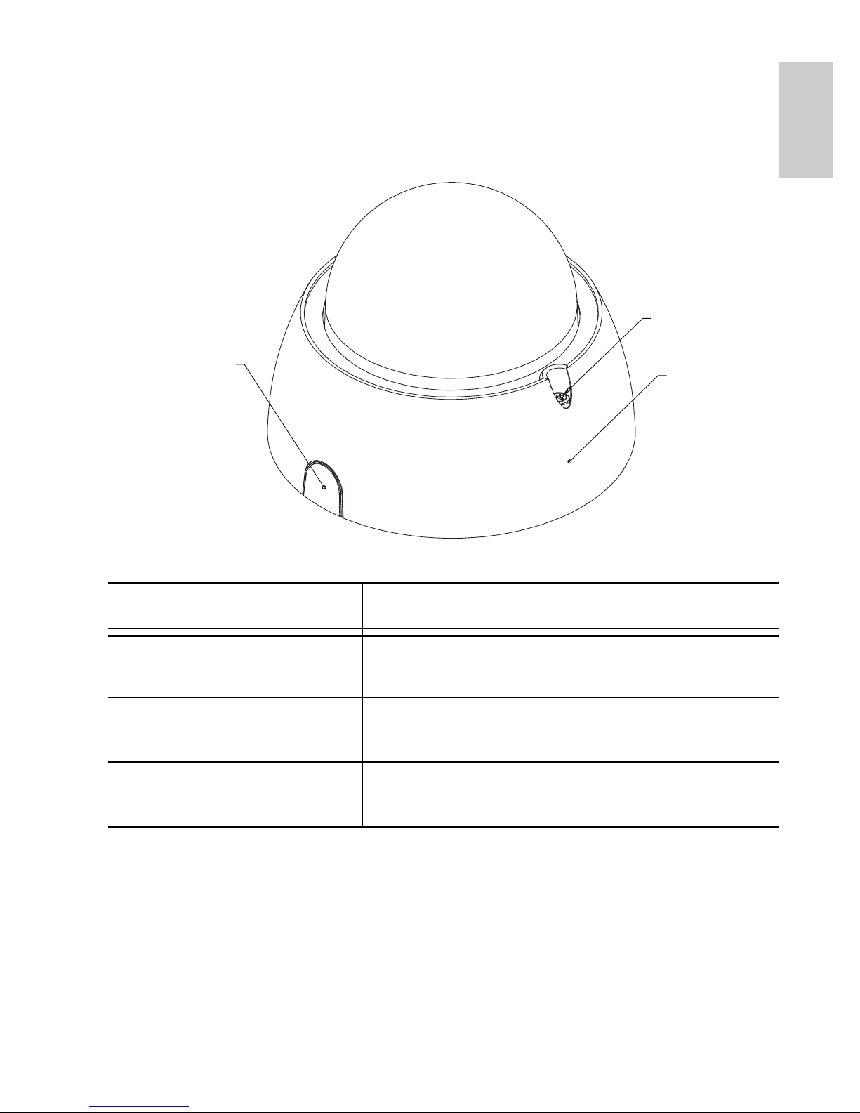
Cover View
Feature Description
Dome Cover Vandal proof dome cover constructed out
of plastic with a polycarbonate bubble.
Tamper Proof Screws TORX tamper-resistant captive screws to
fix the dome cover to the base.
Cable Entry Hole An entry hole for network, power and I/O
cables.
Tamper Proof
Screws
Dome Cover
Cable
Entry Hole
2
English
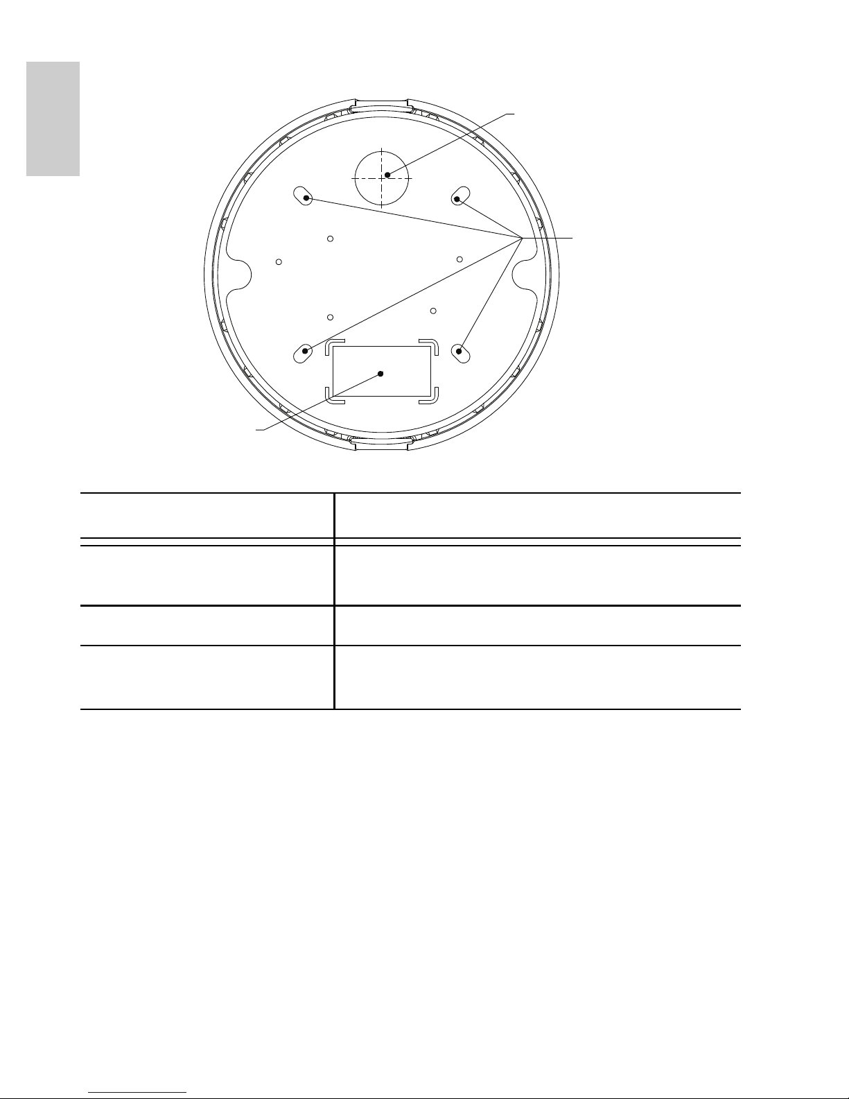
Bottom View
Feature Description
Cable Entry Hole An entry hole for network, power and I/O
cables.
Mounting Holes Mounting points for the dome camera.
Serial Number Tag Product serial number and part number
label.
Cable Entry Hole
Mounting Holes
Serial Number Tag
3
English
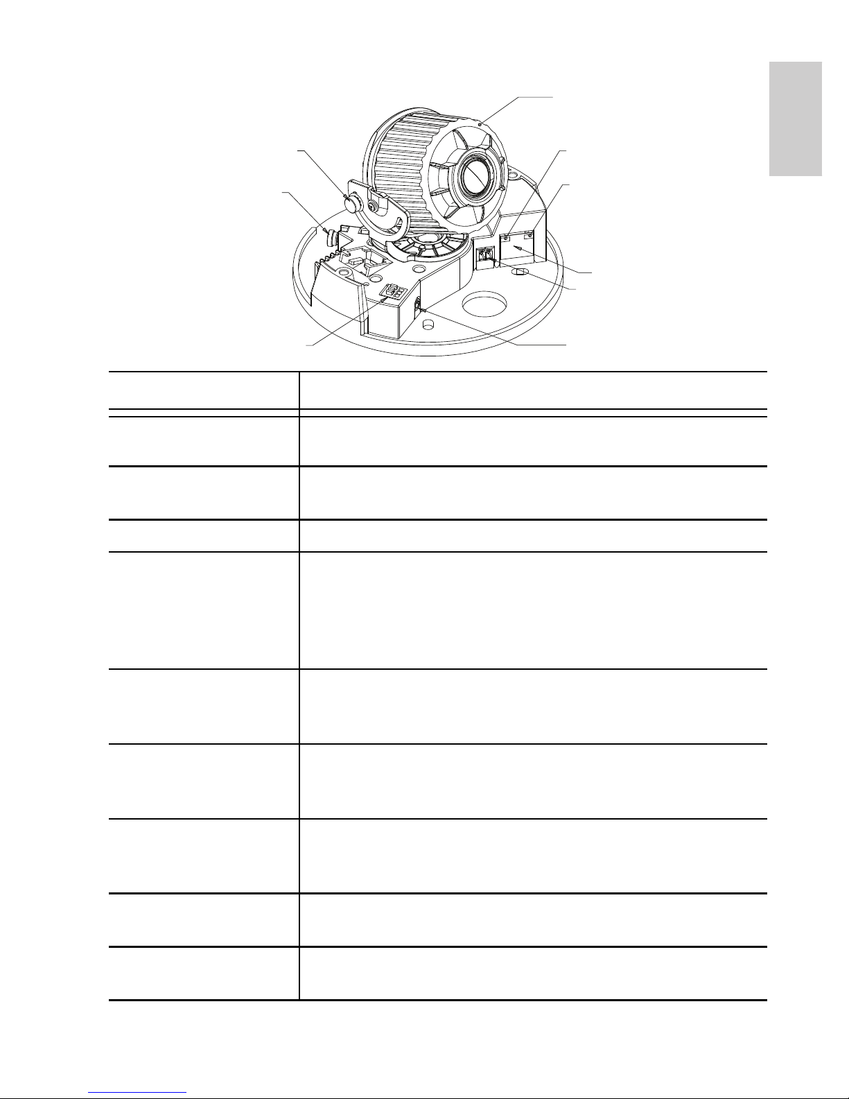
Front View
Feature Description
Tilt Lock Thumb
Screws
Provides a locking mechanism for the image tilt
adjustment.
Pan Lock Thumb
Screws
Provides a locking mechanism for the image pan
adjustment.
Azimuth Control Provides adjustment of the image angle.
Ethernet Port Accepts an Ethernet connection to a network. Server
communication and image data transmission occurs
over this connection. Also receives power when it is
connected to a network that provides Power over
Ethernet.
Power Connector
Block
Accepts a terminal block with either AC or DC power
connection. DC input can be either polarity. Only
required when Power over Ethernet is not available.
Audio/Video
Connector
Accepts a mini-jack connector (3.5 mm). See the section
about connecting microphones and monitors for more
information.
I/O Terminals Provides connections to external input/output devices.
See the section about connecting external devices for
more information.
Connection Status
LED
Provides information about device operation. See LED
indicators for more information.
Link LED Indicates if there is an active connection in the Ethernet
port.
ilt Lock Thumb Screw
Pan Lock Thumb
Screw
I/O Terminals
Link LED
Connection Status LED
Ethernet Port
Power Connector
Block
Audio/Video Connector
Azimuth Control
4
English
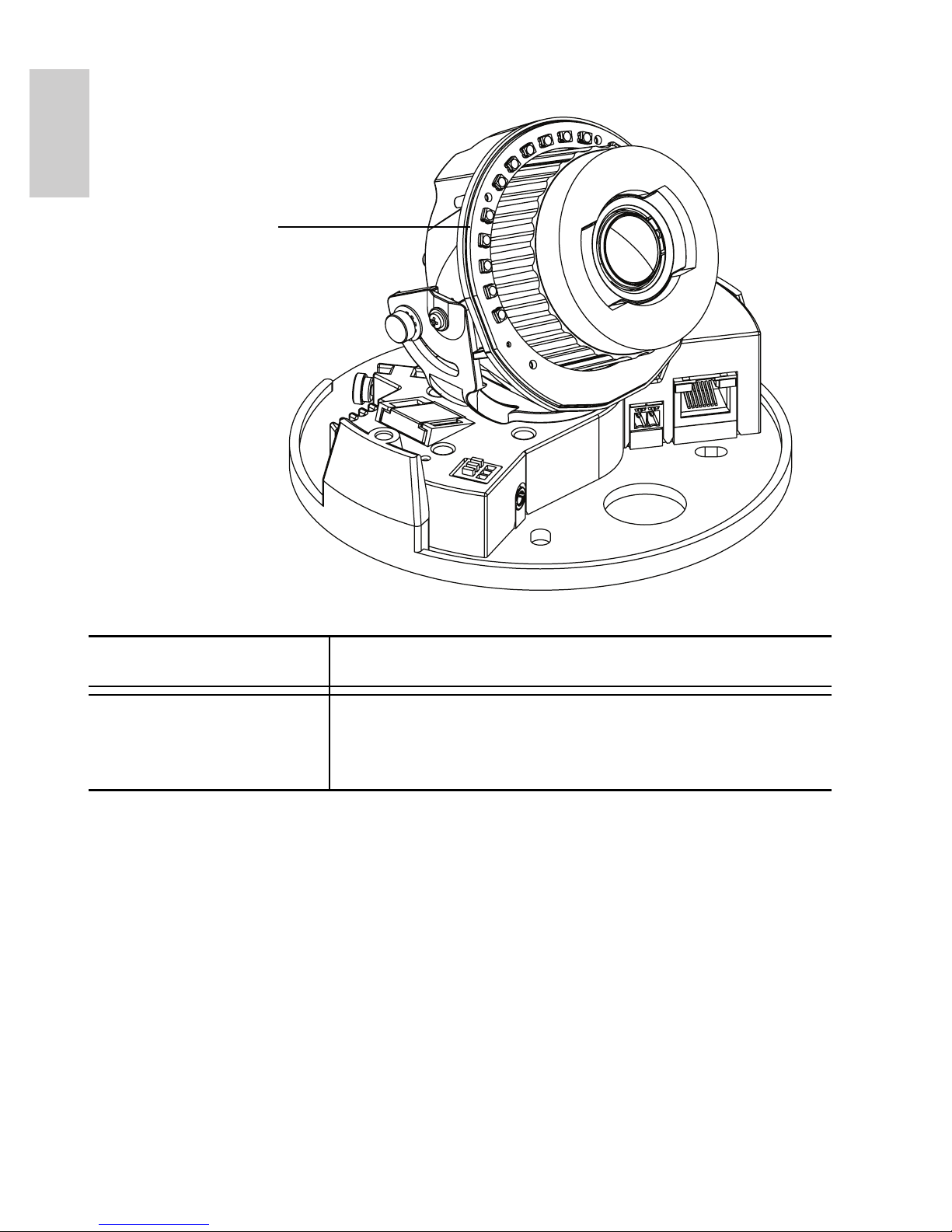
IR View
Feature Description
IR Illuminator Ring Provides scene illumination in the IR
spectrum. The IR illuminator ring is not
included with all models.
IR Illuminator Ring

5
English
Installation
Required Tools and Materials
• Small slotted screwdriver with 5/64” or 2 mm blade width
— for connecting power when not using Power over
Ethernet.
Camera Package Contents
Ensure the package contains the following:
• Avigilon High Definition IP Dome Camera
• Terminal block
• T20 TORX tamper resistant key
• 4 screws and anchors for solid walls
• Drill template sticker
Installation Steps
Complete the following procedures to install the dome camera.
1. Removing the Dome Cover on page 5
2. Mounting the Dome Camera on page 6
3. Connecting Cables on page 7
4. Assigning an IP Address on page 7
5. Accessing the Live Video Stream on page 8
6. Aiming the Dome Camera on page 8
7. Installing the Dome Cover on page 9
8. Focusing the Dome Camera on page 9
Removing the Dome Cover
Remove the dome cover by loosening the tamper-proof screws that fix
the cover to the base. The tamper resistant key included with the
dome camera can be used to loosen the screws.
6
English
NOTE: Be careful not to scratch or touch the dome bubble. The
resulting marks or fingerprints may affect the overall image
quality. Try not to touch the dome bubble and keep the
protective cover on the bubble until after the installation is
complete.
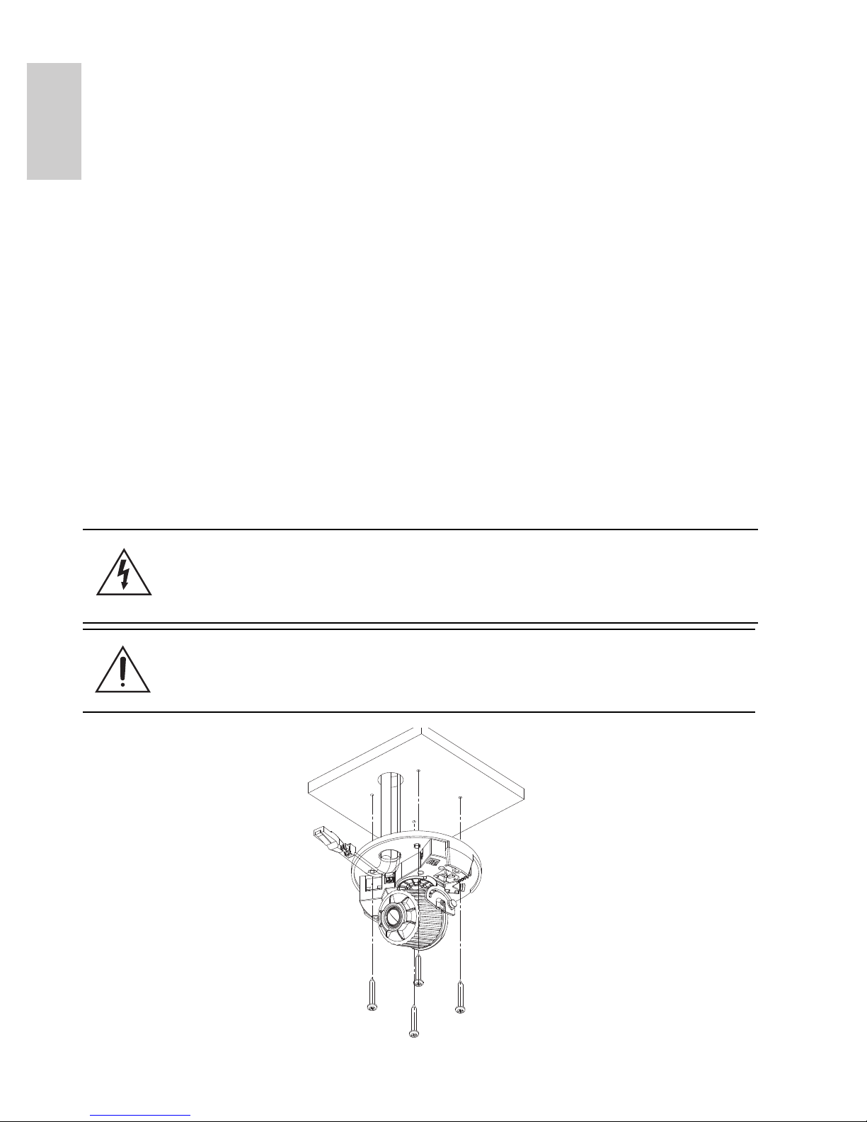
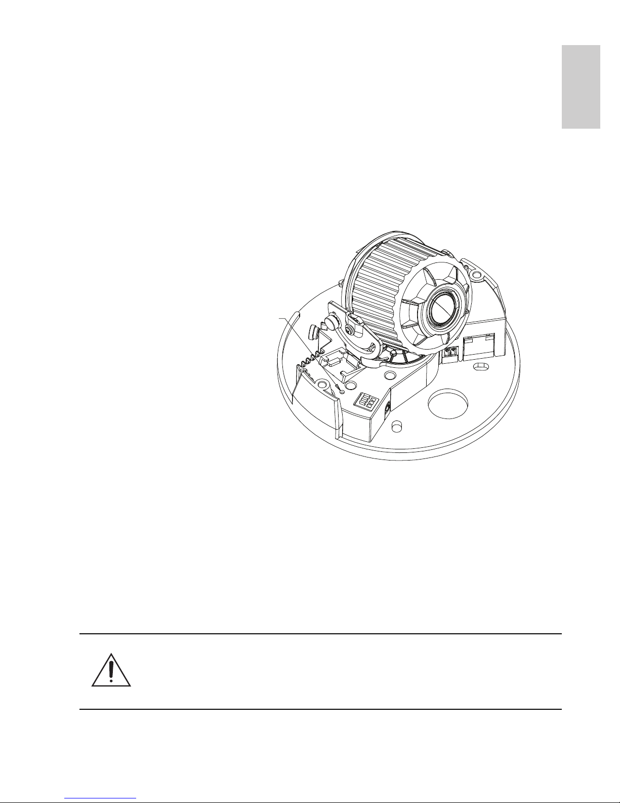
Mounting the Dome Camera
Perform the following steps to mount the dome camera to the ceiling or
wall:
1. Use the drill template to drill four mounting holes and one
cable entry hole in the ceiling or wall.
2. Pull the cables through the cable entry hole in the ceiling
or wall, then through the cable entry hole in the dome
camera.
3. Drive four screws into the mounting holes to fasten the
dome camera to the ceiling or wall.
Figure: Dome camera installation.
Warning — Only use UL listed mounting brackets suitable
for the mounting surface and can sustain a minimum 0.60 kg
(1.2 lbs).
Caution — This camera is designed for indoor use only.

7
English
Connecting Cables
Refer to the diagrams in the Overview section for the location of the
different connectors.
To connect the cables required for proper operation, complete the
following:
1. If there are external input or output devices that need to be
connected to the camera (for example: door contacts,
relays, etc), connect the devices to the camera I/O
Terminals.
For more information, see Connecting to External Devices.
2. If an external microphone or external video monitor needs
to be connected to the camera, connect the devices to the
camera Audio/Video Connector.
For more information, see Connecting to Microphones and
Video Monitors.
3. Connect the Ethernet Port (RJ45 connector) to a network
using an Ethernet network cable. The Link LED will turn on
once a network link has been established.
4. Connect power using one of the following methods:
• Power over Ethernet (PoE) Class 3 — If PoE is
available, the camera is automatically detected
when the network cable is connected.
• External Power — Connect an external 12 VDC or
24 VAC power source to the power connector block.
For more information, see Connecting Power.
5. Check that the Connection Status LED indicates the
correct state.
For more information, see LED Indicators.
Assigning an IP Address
The camera automatically obtains an IP address by default. Once
connected to a network, it attempts to locate and obtain an IP address
from a DHCP server. If this fails, Zero Configuration Networking

8
English
(Zeroconf) is used to choose an IP address. When the IP address is
set using Zeroconf, the IP address is in the 169.254.0.0/16 subnet.
The IP address settings can be changed using one of the following
methods:
• (Recommended) Avigilon Camera Installation Tool
software application.
• Camera's web browser interface:
http://<camera IP address>/
• ARP/Ping method. For more information, see Setting the
IP Address through the ARP/Ping Method.
• Network Video Management software application (for
example, Avigilon Control Center).
NOTE: The default camera username is admin and the default
password is admin.
Accessing the Live Video Stream
Live video stream can be viewed using one of the following methods:
• (Recommended) Avigilon Camera Installation Tool
software application.
• Camera's web browser interface:
http://<camera IP address>/.
• Network Video Management software application (for
example, Avigilon Control Center).
NOTE: The default camera username is admin and the default
password is admin.
Aiming the Dome Camera
1. Loosen the pan and tilt lock screws on the camera.
2. Turn the lens to the desired direction by panning and tilting
the lens.
3. Once satisfied, tighten the pan and tilt lock screws to
secure the dome camera’s position.
4. Rotate the azimuth control ring to set the image to the
correct angle.
9
English
5. In the Avigilon Camera Installation Tool, adjust the
camera’s Image and Display settings to achieve the
desired zoom position.
Installing the Dome Cover
To install the dome cover, complete the following steps:
1. Rotate the black shield located inside the dome bubble so
that it does not block the camera’s field of view. Skip this
step if you are installing a dome camera with IR
illumination.
2. Attach the dome cover to the base by tightening the
tamper-proof screws with the provided tamper resistant
key.
Be especially careful not to mark the dome bubble or the
contaminants will cause unwanted reflections in the -IR
model.
3. Remove the plastic cover on the dome bubble.
Focusing the Dome Camera
NOTE: Ensure this procedure is performed after the dome cover is
installed, so the focus shift caused by the dome bubble’s
refraction can be accomodated.
• In the Avigilon Camera Installation Tool, use the camera’s
Image and Display settings to focus the camera lens.
a. Click the Auto Focus button to focus the lens.
b. If the desired focus was not achieved, use the focus
near and far buttons to adjust the focus.
Caution — Do not attempt to adjust the focus and zoom on
the camera manually or the camera lens may become
damaged.

10
English
For More Information
Additional information about setting up and using the device is
available in the following guides:
• Avigilon Camera Installation Tool User Guide
• Avigilon Control Center Client User Guide
• Avigilon High Definition H.264 Web Interface User Guide
The manuals are available on the Avigilon website:
http://avigilon.com/
#/support-and-downloads.
11
English
Cable Connections
Connecting External Power
NOTE: Do not perform this procedure if Power over Ethernet (POE) is
used.
If PoE is not available, the dome camera needs to be powered through
the removable power connector block. Refer to the diagrams in this
guide for the location of the power connector block.
The device can be powered from 12 VDC or 24 VAC. The power
consumption information is listed in the product specifications.
To connect power to the power connector block, complete the
following steps:
1. Remove the power connector block from the device.
2. Remove the insulation from ¼” (6 mm) of the power wires.
Do not nick or damage the wires.
3. Insert the two power wires into the two terminals on the
power connector block. The connection can be made with
either polarity.
Use a small slotted (5/64” or 2 mm blade width)
screwdriver to loosen and tighten the terminals.
4. Attach the power connector block back into the receptacle
on the device.
Warning — This product is intended to be supplied by a UL
Listed Power Unit marked “Class 2” or “LPS” or “Limited
Power Source” with output rated 12 VDC or 24 VAC, 6 W
min. (10 W min. with -IR model) or PoE rated 48 VDC, 6 W
min. (10 W min. with -IR model).
12
English
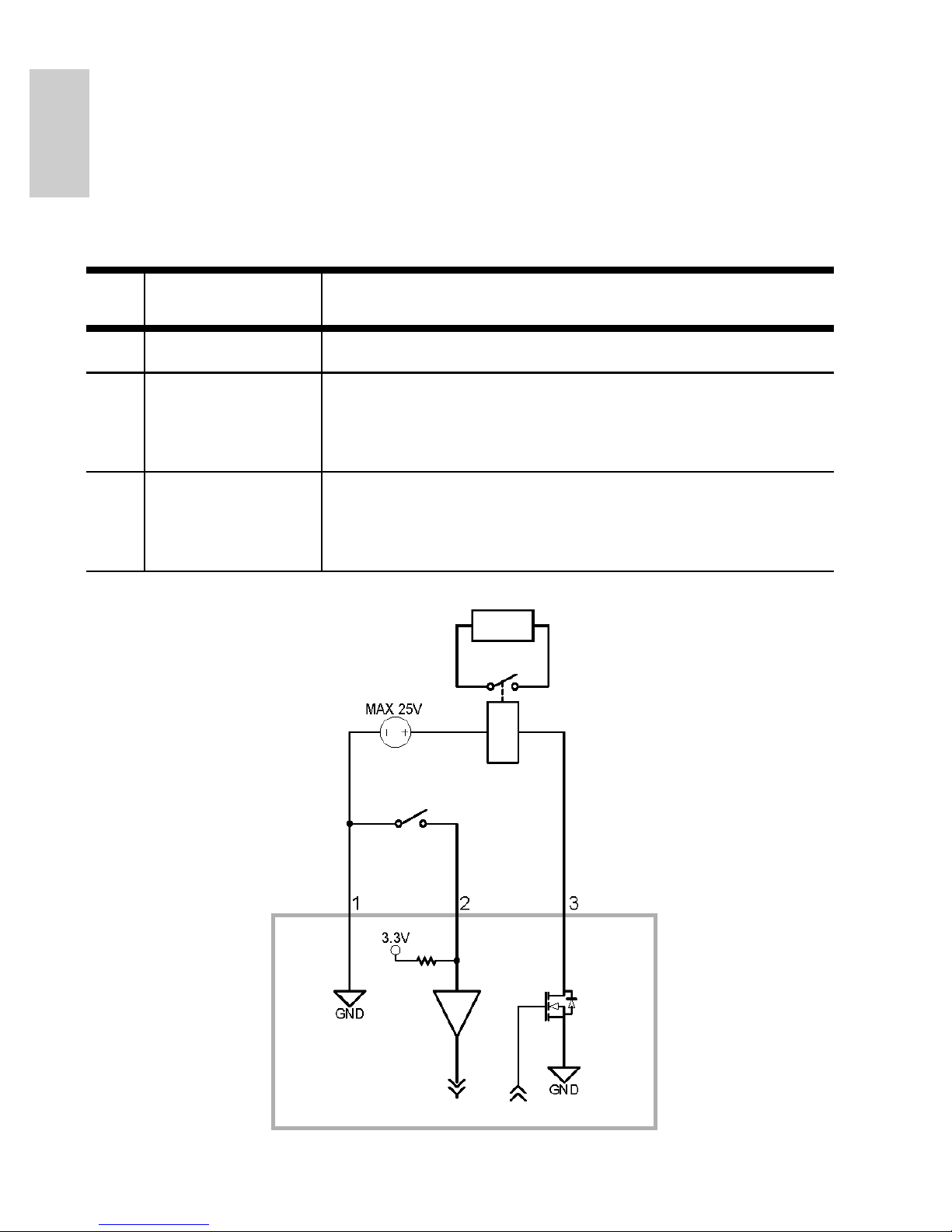
Connecting to External Devices
External devices are connected to the camera through the I/O
terminal. The pinout for the I/O terminal is shown in the following table
and diagram.
Figure: External I/O terminal schematics and example application.
Table:External I/O Terminals
Pin Function Description
1 Ground Ground
2 Input To activate, connect the Input to the Ground
pin. To deactivate, leave disconnected or apply
between 3-15 V.
3 Output When active, Output is internally connected
with the Ground pin. Circuit is open when
inactive. Maximum load is 25 VDC, 120 mA.
Switch
Relay
13
English
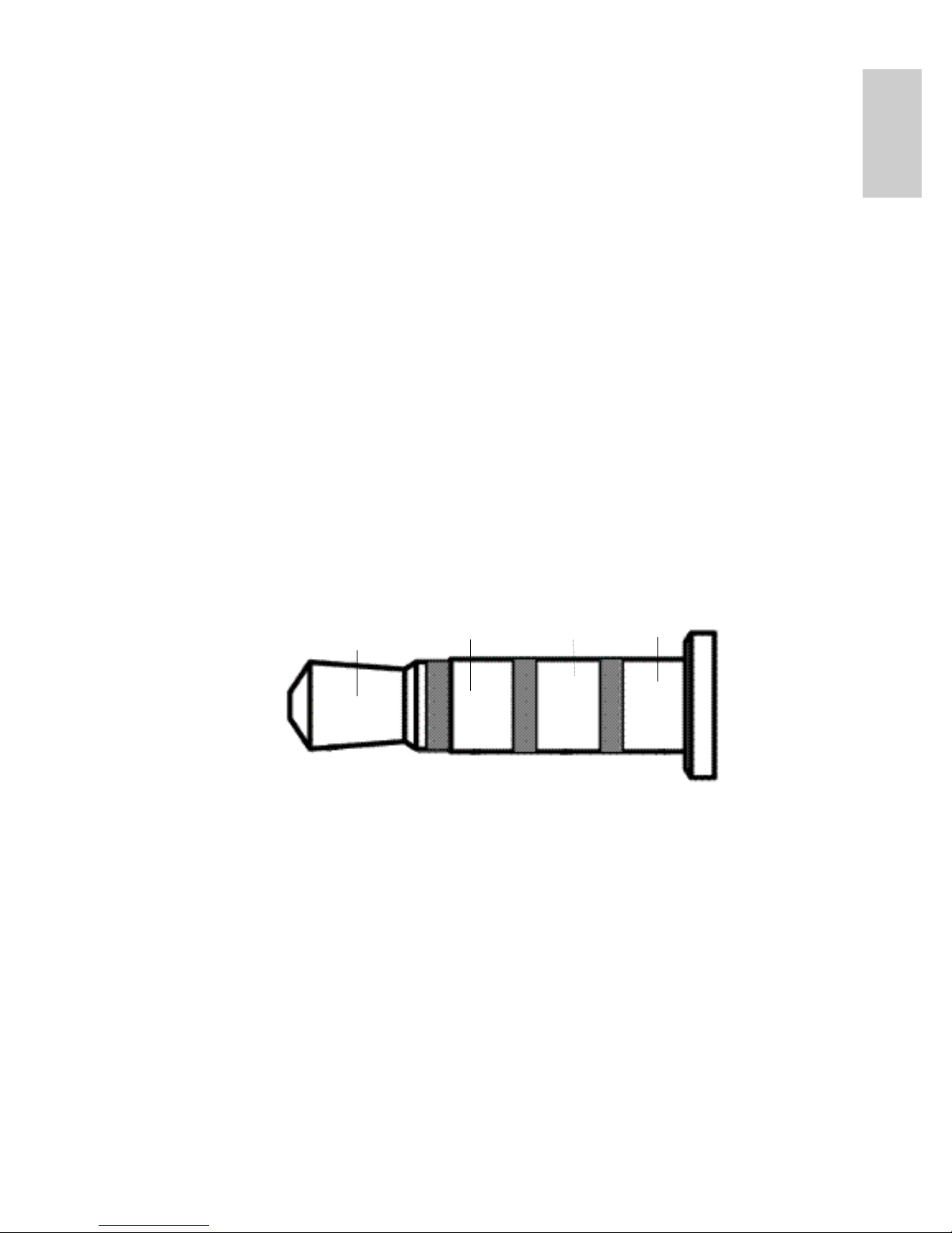
Connecting to Microphones, Speakers
and Video Monitors
The camera can be connected to an external microphone, speaker
and video monitor through the audio/video connector. The connector
is a mini-jack (3.5 mm), and the pinout for it is shown in the following
diagram.
NOTE: The camera only supports line level mono audio input and an
NTSC or PAL video output.
The video output signal is determined by the camera flicker control
setting. When the camera flicker control is set to 60 Hz, the video
output signal is NTSC. When the flicker control is set to 50 Hz, the
video output signal is PAL. Use the Avigilon Camera Installation Tool
to configure the camera’s flicker control in the Image and Display
setup.
Figure: Mini-jack audio video connector.
Audio IN
Composite
Video OUT
GND
Audio
OUT
14
English
LED Indicators
Once the camera is connected to the network, the Connection Status
LED will display the camera’s progress in connecting to the Network
Video Management software.
The following table describes what the LEDs indicate:
Table:LED Indicators
Connection
State
Connection
Status LED
Description
Obtaining IP
Address
One short
flash every
second
Attempting to obtain an IP address.
Discoverable Two short
flashes every
second
Obtained an IP address but is not
connected to the Network Video
Management software.
Upgrading
Firmware
Two short
flashes and
one long flash
every second
Updating the firmware.
Connected On Connected to the Network Video
Management software.
15
English
Reset to Factory Default
Settings
If the camera no longer functions as expected, you can choose to
restore the camera to its factory default settings.
Use the firmware revert button to reset the camera.
Figure: The firmware revert button on the side of the dome camera.
1. Disconnect power from the camera.
2. Using a straightened paperclip or similar tool, gently press
and hold the firmware revert button.
3. While continuing to hold the button, power the device.
Release the button after three seconds.
Caution — Do not apply excessive force. Inserting the tool
too far will damage the device.
Firmware Revert Button

16
English
Setting the IP Address
Through the ARP/Ping Method
Complete the following steps to configure the camera to use a specific
IP address:
1. Locate and copy down the MAC Address (MAC) listed on
the Serial Number Tag for reference.
2. Open a Command Prompt window and enter the following
commands:
a. arp -s <New Camera IP Address> <Camera
MAC Address>
For example: arp -s 192.168.1.10 00-18-
85-12-45-78
b. ping -l 123 -t <New Camera IP Address>
For example: ping -l 123 -t 192.168.1.10
3. Reboot the camera.
4. Close the Command Prompt window when you see the
following message:
Reply from <New Camera IP Address>: ...

17
English
Specifications
H3-D1 H3-D2
Camera
Audio Input Line input, A/V mini-jack (3.5 mm)
Video Output NTSC/PAL, A/V mini-jack (3.5 mm)
Lens 3-9mm, F1.2, P-iris 9-22mm, F1.6, P-Iris
Network
Network 100Base-TX
Cabling Type CAT5
Connector RJ-45
API ONVIF compliant (www.onvif.org)
Security Password protection, HTTPS encryption, digest authentication, WS
authentication, user access log
Protocols IPv4, HTTP, HTTPS, SOAP, DNS, NTP, RTSP, RTCP, RTP, TCP, UDP,
IGMP, ICMP, DHCP, Zeroconf, ARP
Streaming Protocols RTP/UDP, RTP/UDP multicast, RTP/RTSP/TCP, RTP/RTSP/HTTP/
TCP,RTP/RTSP/HTTPS/TCP, HTTP
Mechanical
Dimensions ØxH 138mm x 104mm, 5.4” x 4.1”
Weight 0.53 kg (1.17 lbs)
Dome Bubble Polycarbonate, clear
Body Plastic
Housing Surface mount, tamper resistant
Finish Plastic, RAL 9003
Adjustment Range 360° pan, 180° tilt (122° tilt with -IR option), 180° azimuth
Electrical
Power Consumption 6 W with external power (10 W for -IR option)
6 W with IEEE 802.3af Class 3 PoE (10 W for -IR option)
Power Source VDC: 12 V +/- 10%, 6 W min (10 W min with -IR option)
VAC: 24 V +/- 10%, 8 VA min (12 VA min with -IR option)
PoE: IEEE802.3af Class 3 compliant
Power Connector 2-pin terminal block
Environmental
Operating Temperature -10 °C to +50 °C (14 °F to 122 °F)
Storage Temperature -10 °C to +70 °C (14 °F to 158 °F)
Humidity 20 - 80% Relative humidity (non-condensing)
Certifications
Safety UL 60950 CSA60950 EN 60950-1
CE ROHS WEEE
Electromagnetic Emissions FCC Part 15 Subpart B Class B IC ICES-003 Class B
EN 55022 Class B
Electromagnetic Immunity EN 55024 EN 61000-4-2 EN 61000-4-3
EN 61000-4-4 EN 61000-4-5 EN 61000-4-6
EN 61000-4-11

18
English
Limited Warranty & Technical Support
Avigilon warrants to the original consumer purchaser, that this product will be
free of defects in material and workmanship for a period of 3 years from date of
purchase.
The manufacturer’s liability hereunder is limited to replacement of the product,
repair of the product or replacement of the product with repaired product at the
discretion of the manufacturer. This warranty is void if the product has been
damaged by accident, unreasonable use, neglect, tampering or other causes
not arising from defects in material or workmanship. This warranty extends to
the original consumer purchaser of the product only.
AVIGILON DISCLAIMS ALL OTHER WARRANTIES EXPRESSED OR
IMPLIED INCLUDING, WITHOUT LIMITATION, ANY IMPLIED WARRANTIES
OF MERCHANTABILITY OR FITNESS FOR A PARTICULAR PURPOSE,
EXCEPT TO THE EXTENT THAT ANY WARRANTIES IMPLIED BY LAW
CANNOT BE VALIDLY WAIVED.
No oral or written information, advice or representation provided by Avigilon, its
distributors, dealers, agents or employees shall create another warranty or
modify this warranty. This warranty states Avigilon’s entire liability and your
exclusive remedy against Avigilon for any failure of this product to operate
properly.
In no event shall Avigilon be liable for any indirect, incidental, special,
consequential, exemplary, or punitive damages whatsoever (including but not
limited to, damages for loss of profits or confidential or other information, for
business interruption, for personal injury, for loss of privacy, for failure to meet
any duty including of good faith or of reasonable care, for negligence, and for
any other pecuniary or other loss whatsoever) arising from the use of or inability
to use the product, even if advised of the possibility of such damages. Since
some jurisdictions do not allow the above limitation of liability, such limitation
may not apply to you.
This Limited Warranty gives you specific legal rights and you may also have
other rights which vary from jurisdiction to jurisdiction.
Warranty service and technical support can be obtained by
contacting Avigilon Technical Support by phone at
1.888.281.5182 or via email at support@Avigilon.com.
Guide d'installation
Modèles de caméra dôme IP H.264 haute
définition Avigilon :
1.0-H3-D1, 1.0-H3-D1-IR, 1.0-H3-D2, 2.0-H3-D1, 2.0-H3-D1-IR,
2.0-H3-D2, 3.0W-H3-D1, 3.0W-H3-D1-IR, 3.0W-H3-D2, 5.0-H3-D1,
5.0-H3-D1-IR et 5.0-H3-D2

i
Français
Informations de sécurité
importantes
Ce manuel fournit des informations d'installation et d'exploitation, ainsi
que des précautions d'utilisation pour la caméra dôme. Une
installation incorrecte peut entraîner une défaillance imprévue. Avant
d'installer cet équipement, lisez attentivement ce manuel. Veuillez
remettre ce manuel au propriétaire de l'équipement pour une
utilisation ultérieure.
• N'utilisez pas l'équipement à proximité de l'eau ; ne l'exposez
pas à des éclaboussures ou des fuites. Ne placez aucun objet
rempli de liquide au-dessus de l'équipement.
• N'exposez pas l'équipement à la pluie ou aux moisissures.
• Pour une utilisation en intérieur uniquement.
Si l'équipement est utilisé en extérieur, un adaptateur ou un
boîtier de fixation en extérieur approuvé est obligatoire.
Consultez Avigilon pour plus d'informations.
• L'installation doit être effectuée par un personnel qualifié
uniquement et doit être en conformité avec tous les codes
locaux.
• Ce produit doit être alimenté par une alimentation répertoriée
UL et portant le marquage "Classe 2", "LPS" ou "Limited Power
Le symbole d'avertissement indique la présence de
tensions dangereuses, à l'intérieur et à l'extérieur du
boîtier du produit, susceptibles de générer un risque de
choc électrique, de blessure grave, voire de décès, si
des précautions appropriées ne sont pas prises.
Le symbole Attention alerte l'utilisateur sur la présence
de dangers susceptibles d'infliger aux personnels des
blessures mineures à modérées, d'endommager des
biens ou le produit lui-même si des précautions
appropriées ne sont pas prises.
Warning — Le non-respect des instructions suivantes est
susceptible d'entraîner des blessures graves voire le décès.
ii
Français
Source", d'une capacité de sortie nominale de 12VCC ou 24
VCA pour 6 W minimum (10 W minimum pour un modèle IR),
ou, en mode PoE (Power over Ethernet), de 48 VCC pour 6 W
minimum (10 W minimum pour un modèle IR).
• Toute alimentation externe connectée à ce produit ne peut être
connectée qu'à un autre produit Avigilon de la même gamme
de modèles. Les connexions à des alimentations externes
doivent être correctement isolées.
• Pour quelque raison que ce soit, ne connectez pas
l'équipement directement au secteur.
• N'effectuez aucune installation à proximité de sources de
chaleur telles que radiateurs, bouches de chaleur ou poêles.
• Ne soumettez pas les câbles à des tensions, des charges ou
des pincements excessifs.
• N'ouvrez pas l'équipement, ne le démontez pas. Il ne contient
aucune pièce sur laquelle l'utilisateur peut intervenir.
• Pour toute intervention, contactez un personnel qualifié.
Une intervention peut se révéler nécessaire lorsque
l'équipement est endommagé (par exemple, par le
renversement d'un liquide ou la chute d'un objet), lorsqu'il a été
exposé à la pluie ou à l'humidité (présence de moisissure),
lorsqu'il ne fonctionne pas normalement ou lorsqu'il a chuté.
• N'utilisez pas de détergents puissants ou abrasifs lorsque vous
nettoyez le corps de l'équipement.
• Utilisez uniquement les accessoires recommandés par
Avigilon.
• L'utilisation de commandes, de réglages ou de procédures
autres que ceux spécifiés dans le présent document peut
entraîner une exposition à des radiations dangereuses.
Caution — Le non-respect des instructions suivantes est
susceptible d'entraîner des blessures et d'endommager la
caméra dôme.
 Loading...