

Page 1
Installation Guide
Avigilon High Definition H.264 IP Camera
Models:
1.0-H3-B1, 1.0-H3-B2, 2.0-H3-B1, 2.0-H3-B2, 3.0W-H3-B2
and 5.0-H3-B2
920-0061A-Rev1
Page 2

Page 3
i
English
English
Important Safety Information
This manual provides installation and operation information and
precautions for the use of this camera. Incorrect installation could
cause an unexpected fault. Before installing this equipment read this
manual carefully. Please provide this manual to the owner of the
equipment for future use.
• Do not use near water or expose to dripping or splashing.
Do not place objects filled with liquids above the device.
• Do not expose to rain or moisture.
• For indoor use only.
If used outdoors, an approved outdoor mounting adapter
or enclosure is required. Consult with Avigilon for more
information.
• Installation must be performed by qualified personnel only,
and must conform to all local codes.
• This product is intended to be supplied by a UL Listed
Power Unit marked “Class 2” or “LPS” or “Limited Power
Source” with output rated 12 VDC or 24 VAC, 6 W min. or
Power over Ethernet (PoE), rated 48 VDC, 6 W min.
• Any external power supply connected to this product may
only be connected to another Avigilon product of the same
The Warning symbol indicates the presence of dangerous
voltage within and outside the product enclosure that may
constitute a risk of electric shock, serious injury or death to
persons if proper precautions are not followed.
The Caution symbol alerts the user to the presence of hazards
that may cause minor or moderate injury to persons, damage to
property or damage to the product itself if proper precautions
are not followed.
Warning — Failure to observe the following instructions
may result in severe injury or death.
Page 4
ii
English
English
model series. External power connections must be
properly insulated.
• Do not connect directly to mains power for any reason.
• Do not install near any heat sources such as radiators,
heat registers, stoves, or other sources of heat.
• Do not subject the cables to excessive stress, heavy loads
or pinching.
• Do not open or disassemble the device. There are no user
serviceable parts.
• Refer all servicing to qualified personnel.
Servicing may be required when the device has been
damaged (such as from a liquid spill or fallen objects), has
been exposed to rain or moisture, does not operate
normally, or has been dropped.
• Do not use strong or abrasive detergents when cleaning
the device body.
• Use only accessories recommended by Avigilon.
• Use only UL-listed mounting bracket suitable for the
mounting surface and minimum 0.7 kg (1.5 lb) weight.
• Use of controls or adjustments or performance of
procedures other than those specified in this document
may result in hazardous radiation exposure.
Caution — Failure to observe the following instructions
may result in injury or damage to the camera.
Page 5
iii
English
English
Regulatory Notices
This device complies with part 15 of the FCC Rules. Operation is
subject to the following two conditions: (1) This device may not cause
harmful interference, and (2) this device must accept any interference
received, including interference that may cause undesired operation.
This Class B digital apparatus complies with Canadian ICES-003.
FCC Notice
This equipment has been tested and found to comply with the limits for
a Class B computing device pursuant to Subpart B of Part 15 of FCC
rules, which are designed to provide reasonable protection against
such interference when operated in a commercial environment.
Operation of this equipment in a residential area is likely to cause
interference, in which case the user at his/her own expense will be
required to take whatever measures may be required to correct the
interference.
Changes or modifications made to this equipment not expressly
approved by Avigilon Corporation or parties authorized by Avigilon
Corporation could void the user’s authority to operate this equipment.
Disposal and Recycling Information
When this product has reached the end of its useful life, please
dispose of it according to your local environmental laws and
guidelines.
European Union:
This symbol means that according to local laws and regulations your
product should be disposed of separately from household waste. When
this product reaches its end of life, take it to a collection point
designated by local authorities. Some collection points accept products
for free. The separate collection and recycling of your product at the
time of disposal will help conserve natural resources and ensure that it
is recycled in a manner that protects human health and the
environment.
Page 6

iv
English
English
Other Notices
Compilation and Publication Notice
This manual has been compiled and published covering the latest
product descriptions and specifications. The contents of this manual
and the specifications of this product are subject to change without
notice. Avigilon reserves the right to make changes without notice in
the specifications and materials contained herein and shall not be
responsible for any damages (including consequential) caused by
reliance on the materials presented, including but not limited to
typographical and other errors relating to the publication.
Intellectual Property Notice
No license is granted by implication or otherwise under any industrial
design, industrial design rights, patent, patent rights, or copyrights of
Avigilon Corporation or its licensors. Trademarks and registered
trademarks are the property of their respective owners.
Page 7

English
English
Table of Contents
Overview . . . . . . . . . . . . . . . . . . . . . . . . . . . . . . 1
Front View . . . . . . . . . . . . . . . . . . . . . . . . . . . . . . . .1
Rear View . . . . . . . . . . . . . . . . . . . . . . . . . . . . . . . . .2
Installation . . . . . . . . . . . . . . . . . . . . . . . . . . . . . 3
Required Tools and Materials . . . . . . . . . . . . . . . . .3
Camera Package Contents . . . . . . . . . . . . . . . . . . .3
Installation Steps . . . . . . . . . . . . . . . . . . . . . . . . . . . 3
Mounting the Camera . . . . . . . . . . . . . . . . . .3
Connecting Cables . . . . . . . . . . . . . . . . . . . . 4
Assigning an IP Address . . . . . . . . . . . . . . . .5
Accessing the Live Video Stream . . . . . . . . . 5
Aiming and Focusing the Camera . . . . . . . . . 6
For More Information . . . . . . . . . . . . . . . . . .6
Cable Connections . . . . . . . . . . . . . . . . . . . . . . 7
Connecting Power . . . . . . . . . . . . . . . . . . . . . . . . . . 7
Connecting to External Devices . . . . . . . . . . . . . . . .8
Connecting to Microphones, Speakers
and Video Monitors . . . . . . . . . . . . . . . . . . . . . . . . . 9
LED Indicators . . . . . . . . . . . . . . . . . . . . . . . . 10
Reset to Factory Default Settings . . . . . . . . . 11
Setting the IP Address Through the ARP/Ping
Method . . . . . . . . . . . . . . . . . . . . . . . . . . . . . . . 12
Specifications . . . . . . . . . . . . . . . . . . . . . . . . . 13
Limited Warranty & Technical Support . . . . 14
Page 8

English
English
Page 9
1
English
English
Overview
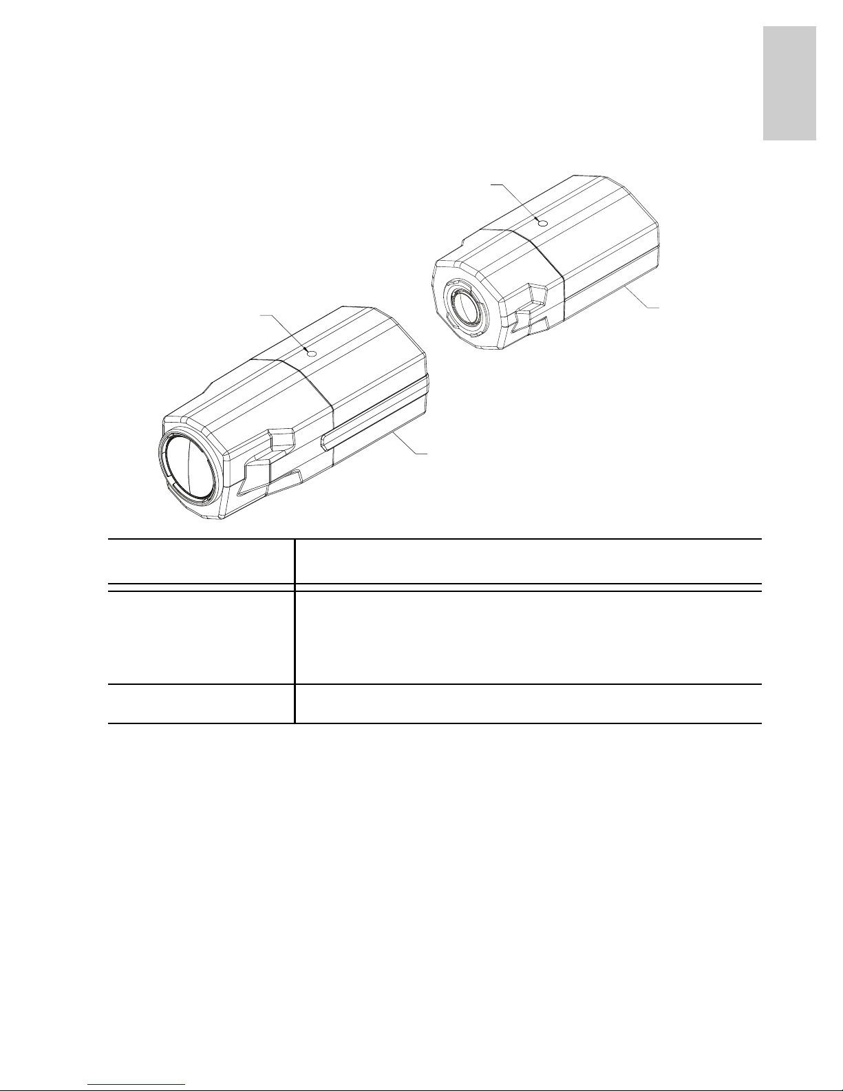
Front View
Feature Description
Camera Mounts Mounting points for the camera.
Mounts accept 1/4” - 20 UNC bolts commonly
found on mounting brackets.
Serial Number Tag Product serial number and part number label.
Serial
Number Tag
Camera Mount
(Top and Bottom)
Serial
Number Tag
Camera Mount
(Top and Bottom)
Page 10
2
English
English
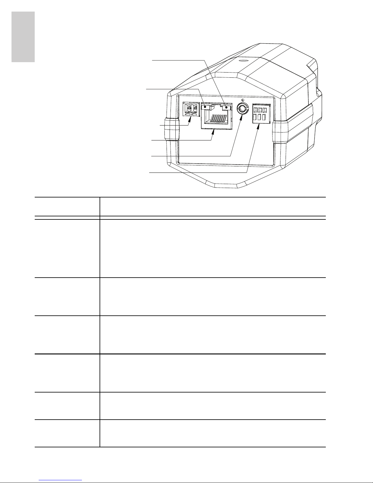
Rear View
Feature Description
Ethernet Port Accepts an Ethernet connection to a network. Server
communication and image data transmission occurs
over this connection. Also receives power when it is
connected to a network that provides Power over
Ethernet.
Power
Connector
Block
Accepts a terminal block with either AC or DC power
connection. DC input can be either polarity. Only
required when Power over Ethernet is not available.
Audio/Video
Connector
Accepts a mini-jack connector (3.5 mm). See the
section about connecting microphones and monitors
for more information.
I/O Terminals Provides connections to external input/output
devices. See the section about connecting external
devices for more information.
Connection
Status LED
Provides information about device operation. See the
section about LED indicators for more information.
Link LED Indicates if there is an active connection in the
Ethernet port.
Connection Status LED
Link LED
Power Connector Block
Ethernet Port
Audio/Video Connector
I/O Terminals
Page 11

3
English
English
Installation
Required Tools and Materials
• Small slotted screwdriver with 5/64” or 2 mm blade width
— for connecting power when not using Power over
Ethernet.
• Mounting bracket, enclosure or tripod.
Camera Package Contents
Ensure the package contains the following:
• Avigilon High Definition IP Camera
• Terminal block
Installation Steps
Complete the following procedures to install the camera.
1. Mounting the Camera on page 3
2. Connecting Cables on page 4
3. Assigning an IP Address on page 5
4. Accessing the Live Video Stream on page 5
5. Aiming and Focusing the Camera on page 6
Mounting the Camera
Camera mounting points are provided on both the top and bottom of
the camera body. Use these mounting points to mount the camera on
a bracket, in an enclosure, or on a tripod. The mounting points have
¼”-20 UNC threaded holes which allow them to accept standard
photographic mounting bolts.
Consult the installation instructions provided with the bracket,
enclosure or tripod for detailed mounting instructions.
Page 12
4
English
English
Connecting Cables
Refer to the diagrams in the Overview section for the location of the
different connectors.
To connect the cables required for proper operation, complete the
following:
1. If there are external input or output devices that need to be
connected to the camera (for example: door contacts,
relays, etc), connect the devices to the camera I/O
Terminals.
For more information, see Connecting to External Devices.
2. If an external microphone or external video monitor needs
to be connected to the camera, connect the devices to the
camera Audio/Video Connector.
For more information, see Connecting to Microphones and
Video Monitors.
3. Connect the Ethernet Port (RJ45 connector) to a network
using an Ethernet network cable. The Link LED will turn on
once a network link has been established.
4. Connect power using one of the following methods:
• Power over Ethernet (PoE) Class 3 — If PoE is
available, the camera is automatically detected
when the network cable is connected.
• External Power — Connect an external 12 VDC or
24 VAC power source to the power connector block.
For more information, see Connecting Power.
Caution — This camera is designed for indoor use only.
Warning — Use only UL-listed mounting bracket suitable for
the mounting surface and minimum 0.7 kg (1.5 lb) weight.
Page 13

5
English
English
5. Check that the Connection Status LED indicates the
correct state.
For more information, see LED Indicators.
Assigning an IP Address
The camera automatically obtains an IP address by default. Once
connected to a network, it attempts to locate and obtain an IP address
from a DHCP server. If this fails, Zero Configuration Networking
(Zeroconf) is used to choose an IP address. When the IP address is
set using Zeroconf, the IP address is in the 169.254.0.0/16 subnet.
The IP address settings can be changed using one of the following
methods:
• (Recommended) Avigilon Camera Installation Tool
software application.
• Camera's web browser interface:
http://<camera IP address>/
• ARP/Ping method. For more information, see Setting the
IP Address through the ARP/Ping Method.
• Network Video Management software application (for
example, Avigilon Control Center).
NOTE: The default camera username is admin and the default
password is admin.
Accessing the Live Video Stream
Live video stream can be viewed using one of the following methods:
• (Recommended) Avigilon Camera Installation Tool
software application.
• Camera's web browser interface:
http://<camera IP address>/.
• Network Video Management software application (for
example, Avigilon Control Center).
NOTE: The default camera username is admin and the default
password is admin.
Page 14
6
English
English
Aiming and Focusing the Camera
Use the Avigilon Camera Installation Tool to aim and focus the
camera. Consult the software user guide for more information.
1. In the Image and Display settings dialog box, use the
Zoom controls to achieve the desired zoom position for the
camera.
2. In the Image and Display settings dialog box, use the Auto
Focus button to focus the lens.
If the desired focus position was not achieved, use the
focus near and far buttons to adjust the focus.
For More Information
Additional information about setting up and using the device is
available in the following guides:
• Avigilon Camera Installation Tool User Guide
• Avigilon Control Center Client User Guide
• Avigilon High Definition H.264 IP Camera User Guide
The manuals are available on the Avigilon website:
http://avigilon.com/
support/manuals/.
Caution — Do not attempt to adjust the focus and zoom on
the camera itself or the camera lens may become damaged.
Page 15
7
English
English
Cable Connections
Connecting Power
NOTE: Do not perform this procedure if Power over Ethernet (POE) is
used.
If PoE is not available, the camera needs to be powered through the
removable power connector block. Refer to the diagrams in this guide
for the location of the power connector block.
The device can be powered from 12 VDC or 24 VAC. The power
consumption information is listed in the product specifications.
To connect power to the power connector block, complete the
following steps:
1. Remove the power connector block from the device.
2. Remove the insulation from ¼” (6 mm) of the power wires.
Do not nick or damage the wires.
3. Insert the two power wires into the two terminals on the
power connector block. The connection can be made with
either polarity.
Use a small slotted (5/64” or 2 mm blade width)
screwdriver to loosen and tighten the terminals.
4. Attach the power connector block back into the receptacle
on the device.
Warning — This product is intended to be supplied by a UL
Listed Power Unit marked “Class 2” or “LPS” or “Limited
Power Source” with output rated 12 VDC or 24 VAC, 6 W
min. or PoE rated 48 VDC, 6 W min.
Page 16
8
English
English
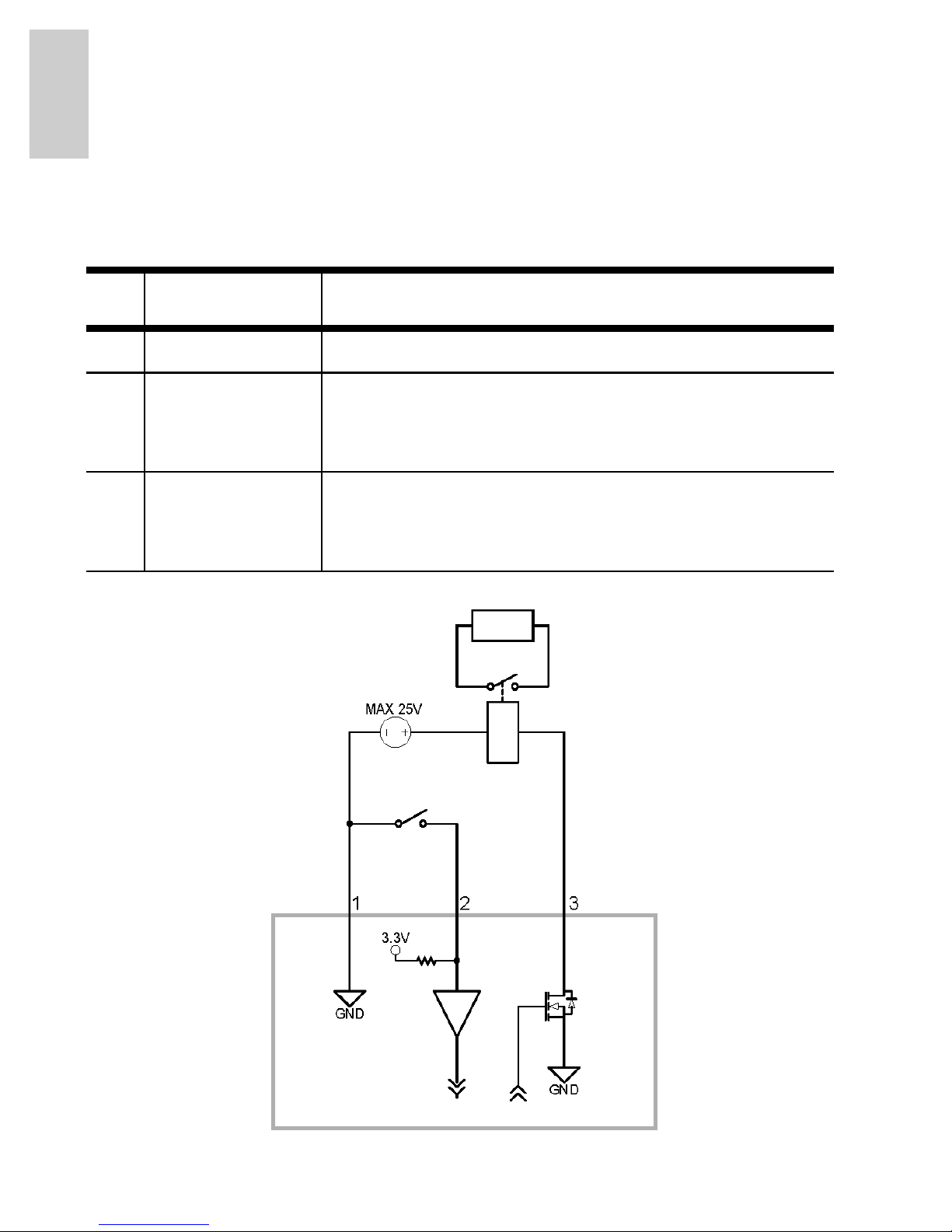
Connecting to External Devices
External devices are connected to the camera through the I/O
terminal. The pinout for the I/O terminal is shown in the following table
and diagram.
Figure: External I/O terminal schematics and example application.
Table:External I/O Terminals
Pin Function Description
1 Ground Ground
2 Input To activate, connect the Input to the Ground
pin. To deactivate, leave disconnected or apply
between 3-15 V.
3 Output When active, Output is internally connected
with the Ground pin. Circuit is open when
inactive. Maximum load is 25 VDC, 120 mA.
Switch
Relay
Page 17
9
English
English
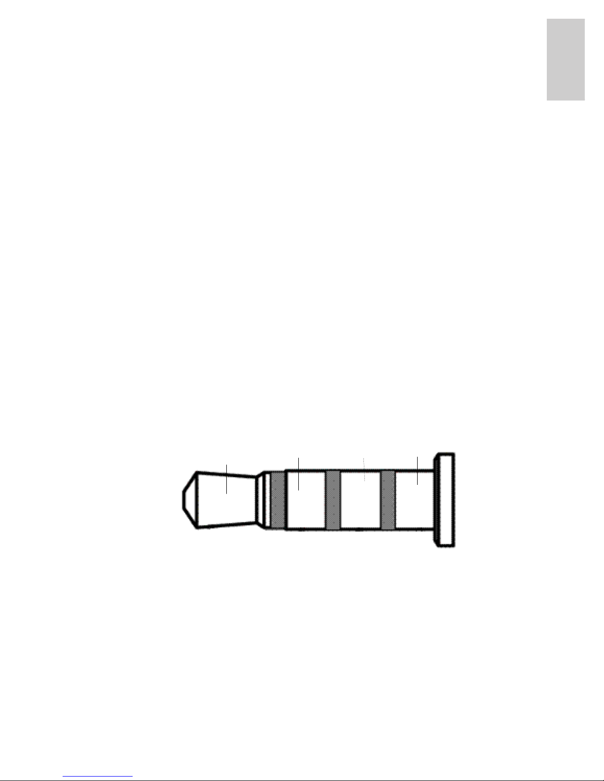
Connecting to Microphones, Speakers
and Video Monitors
The camera can be connected to an external microphone, speaker
and video monitor through the audio/video connector. The connector
is a mini-jack (3.5 mm), and the pinout for it is shown in the following
diagram.
NOTE: The camera only supports line level mono audio input and an
NTSC or PAL video output.
The video output signal is determined by the camera flicker control
setting. When the camera flicker control is set to 60 Hz, the video
output signal is NTSC. When the flicker control is set to 50 Hz, the
video output signal is PAL. Use the Avigilon Camera Installation Tool
to configure the camera’s flicker control in the Image and Display
setup.
NOTE: Video output is disabled when the camera is encoding multiple
H264 or JPEG streams. Use the Avigilon Camera Installation
Tool to configure the camera’s Compression and Image Rate
setup.
Figure: Mini-jack audio video connector.
Audio IN
Composite
Video OUT
GND
Audio
OUT
Page 18
10
English
English
LED Indicators
Once the camera is connected to the network, the connection status
LEDs will display the camera’s progress in connecting to the Network
Video Management software.
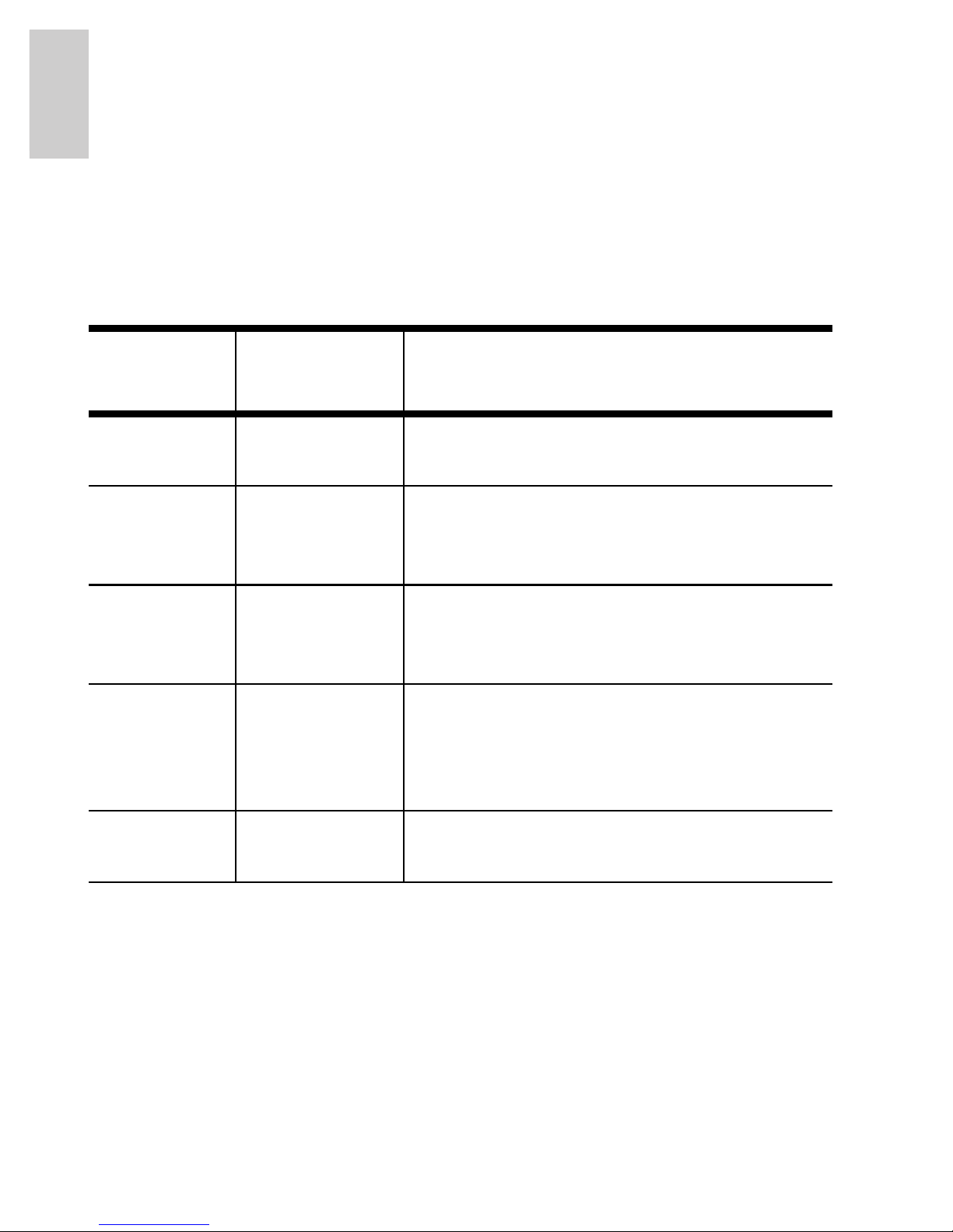
The following table describes what the LEDs indicate:
Table:LED Indicators
Connection
State
Connection
Status LED
Description
No Link Off Not physically connected to any
network device.
Obtaining IP
Address
One short
flash every
second
Attempting to obtain an IP address.
Connecting
to NVR
Two short
flashes every
second
An IP address has been obtained and
is attempting to connect to the server
Upgrading
Firmware
Two short
flashes and
one long flash
every second
Updating the firmware.
Connected On Connected to the Network Video
Management software.
Page 19

11
English
English
Reset to Factory Default Settings
If the camera no longer functions as expected, you can choose to
restore the camera to its factory default settings.
Use the firmware revert button to reset the camera.
Figure: The firmware revert microswitch on the rear of the camera.
1. Disconnect power from the camera.
2. Using a straightened paperclip or similar tool, gently press
and hold the firmware revert microswitch.
3. While continuing to hold the microswitch, power the
device. Release the microswitch after three seconds.
Caution — Do not apply excessive force. Inserting the tool
too far will damage the device.
Firmware Revert Button
Page 20

12
English
English
Setting the IP Address
Through the ARP/Ping Method
Complete the following steps to configure the camera to use a specific
IP address:
1. Locate and copy down the MAC Address (MAC) listed on
the Serial Number Tag for reference.
2. Open Command Prompt.
From the Windows Start menu, select Run... then enter
cmd in the Run dialog box and click OK.
3. In Command Prompt, enter the following commands:
a. arp -s <New Camera IP Address> <Camera
MAC Address>
For example: arp -s 192.168.1.10 00-18-
85-12-45-78
b. ping -l 123 -t <New Camera IP Address>
For example: ping -l 123 -t 192.168.1.10
4. Reboot the camera.
5. Close Command Prompt when you see the following
message:
Reply IP from <New Camera IP Address>: ...
Page 21

13
English
English
Specifications
H3-B1 H3-B2
Camera
Audio Input Line input, A/V mini-jack (3.5 mm)
Video Output NTSC/PAL, A/V mini-jack (3.5 mm)
Lens 4.7-84.6mm, F1.6, auto iris 3-9mm, F1.2, P-Iris
Network
Network 100Base-TX
Cabling Type CAT5
Connector RJ-45
API ONVIF compliant (
www.onvif.org)
Security Password protection, HTTPS encryption, digest authentication, WS
authentication, user access log
Protocols IPv4, HTTP, HTTPS, SOAP, DNS, NTP, RTSP, RTCP, RTP, TCP, UDP, IGMP,
ICMP, DHCP, Zeroconf, ARP
Streaming Protocols RTP/UDP, RTP/UDP multicast, RTP/RTSP/TCP, RTP/RTSP/HTTP/TCP,RTP/
RTSP/HTTPS/TCP, HTTP
Mechanical
Dimensions ØxH 156 mm x 69 mm x 64 mm
6.1” x 2.7” x 2.5”
115 mm x 67 mm x 53 mm
4.5” x 2.6” x 2.5”
Weight 0.56 kg (1.2 lbs) 0.47 kg (1.0 lbs)
Camera Mount 1/4” UNC-20 (top and bottom)
Electrical
Power Source VDC: 12 V
VAC: 24 V
PoE: IEEE802.3af Class 3 compliant
Power Consumption 6 W
Power Connector 2-pin terminal block
Environmental
Operating Temperature -10 °C to +50 °C (14 °F to 122 °F)
-10 °C to +45 °C (14 °F to 113 °F) (with 12 VDC power source)
Storage Temperature -10 °C to +70 °C (14 °F to 158 °F)
Humidity 20 - 80% Relative humidity (non-condensing)
Certifications
Safety UL 60950 CSA 60950 EN 60950-1
CE ROHS WEEE
Electromagnetic Emissions FCC Part 15 Subpart B Class B IC ICES-003 Class B
EN 55022 Class B
Electromagnetic Immunity EN 55024 EN 61000-4-2 EN 61000-4-3
EN 61000-4-4 EN 61000-4-5 EN 61000-4-6
EN 61000-4-11
Page 22

14
English
English
Limited Warranty & Technical Support
Avigilon warrants to the original consumer purchaser, that this product will
be free of defects in material and workmanship for a period of 3 years
from date of purchase. The manufacturer’s liability hereunder is limited to
replacement of the product, repair of the product or replacement of the
product with repaired product at the discretion of the manufacturer. This
warranty is void if the product has been damaged by accident,
unreasonable use, neglect, tampering or other causes not arising from
defects in material or workmanship. This warranty extends to the original
consumer purchaser of the product only.
AVIGILON DISCLAIMS ALL OTHER WARRANTIES EXPRESSED OR
IMPLIED INCLUDING, WITHOUT LIMITATION, ANY IMPLIED
WARRANTIES OF MERCHANTABILITY OR FITNESS FOR A
PARTICULAR PURPOSE, EXCEPT TO THE EXTENT THAT ANY
WARRANTIES IMPLIED BY LAW CANNOT BE VALIDLY WAIVED.
No oral or written information, advice or representation provided by
Avigilon, its distributors, dealers, agents or employees shall create
another warranty or modify this warranty. This warranty states Avigilon’s
entire liability and your exclusive remedy against Avigilon for any failure of
this product to operate properly.
In no event shall Avigilon be liable for any indirect, incidental, special,
consequential, exemplary, or punitive damages whatsoever (including but
not limited to, damages for loss of profits or confidential or other
information, for business interruption, for personal injury, for loss of
privacy, for failure to meet any duty including of good faith or of reasonable
care, for negligence, and for any other pecuniary or other loss
whatsoever) arising from the use of or inability to use the product, even if
advised of the possibility of such damages. Since some jurisdictions do
not allow the above limitation of liability, such limitation may not apply to
you.
This Limited Warranty gives you specific legal rights and you may also
have other rights which vary from jurisdiction to jurisdiction.
Warranty service and technical support can be obtained by
contacting Avigilon Technical Support by phone at
1.888.281.5182 or via email at support@Avigilon.com.
Page 23

Page 24

Page 25
Guide d'installation
Modèles de caméra IP H.264 haute
définition Avigilon :
1.0-H3-B1, 1.0-H3-B2, 2.0-H3-B1, 2.0-H3-B2, 3.0W-H3-B2
e 5.0-H3-B2
Page 26

Page 27
i
Français
Informations de sécurité
importantes
Ce manuel fournit des informations d'installation et d'exploitation, ainsi
que des précautions d'utilisation pour la caméra. Une installation
incorrecte peut entraîner une défaillance imprévue. Avant d'installer
cet équipement, lisez attentivement ce manuel. Veuillez remettre ce
manuel au propriétaire de l'équipement pour une utilisation ultérieure.
• N'utilisez pas l'équipement à proximité de l'eau ; ne l'exposez
pas à des éclaboussures ou des fuites. Ne placez aucun objet
rempli de liquide au-dessus de l'équipement.
• N'exposez pas l'équipement à la pluie ou aux moisissures.
• Pour une utilisation en intérieur uniquement.
Si l'équipement est utilisé en extérieur, un adaptateur ou un
boîtier de fixation en extérieur approuvé est obligatoire.
Consultez Avigilon pour plus d'informations.
• L'installation doit être effectuée par un personnel qualifié
uniquement et doit être en conformité avec tous les codes
locaux.
• Ce produit doit être alimenté par une alimentation répertoriée
UL et portant le marquage "Classe 2", "LPS" ou "Limited Power
Source", d'une capacité de sortie nominale de 12 VCC ou
Le symbole d'avertissement indique la présence de tensions
dangereuses, à l'intérieur et à l'extérieur du boîtier du produit,
susceptibles de générer un risque de choc électrique, de
blessure grave, voire de décès, si des précautions appropriées
ne sont pas prises.
Le symbole Attention alerte l'utilisateur sur la présence de
dangers susceptibles d'infliger aux personnels des blessures
mineures à modérées, d'endommager des biens ou le produit
lui-même si des précautions appropriées ne sont pas prises.
Avertissement — Le non-respect des instructions suivantes
est susceptible d'entraîner des blessures graves voire le
décès.
Page 28
ii
Français
24 VCA pour 6 W min. ou, en mode PoE (Power over
Ethernet), de 48 VCC pour 6 W min.
• Toute alimentation externe connectée à ce produit ne peut être
connectée qu'à un autre produit Avigilon de la même gamme
de modèles. Les connexions à des alimentations externes
doivent être correctement isolées.
• Pour quelque raison que ce soit, ne connectez pas
l'équipement directement au secteur.
• N'effectuez aucune installation à proximité de sources de
chaleur telles que radiateurs, bouches de chaleur ou poêles.
• Ne soumettez pas les câbles à des tensions, des charges ou
des pincements excessifs.
• N'ouvrez pas l'équipement, ne le démontez pas. Il ne contient
aucune pièce sur laquelle l'utilisateur peut intervenir.
• Pour toute intervention, contactez un personnel qualifié.
Une intervention peut se révéler nécessaire lorsque
l'équipement est endommagé (par exemple, par le
renversement d'un liquide ou la chute d'un objet), lorsqu'il a été
exposé à la pluie ou à l'humidité (présence de moisissure),
lorsqu'il ne fonctionne pas normalement ou lorsqu'il a chuté.
• N'utilisez pas de détergents puissants ou abrasifs lorsque vous
nettoyez le corps de l'équipement.
• Utilisez uniquement les accessoires recommandés par
Avigilon.
• Utilisez uniquement un support de fixation répertorié UL
adapté à la surface de montage et capable de supporter un
poids minimal de 0,7 kg (1,5 lbs).
• L'utilisation de commandes, de réglages ou de procédures
autres que ceux spécifiés dans le présent document peut
entraîner une exposition à des radiations dangereuses.
Attention — Le non-respect des instructions suivantes est
susceptible d'entraîner des blessures et d'endommager la
caméra.
Page 29
iii
Français
Avis concernant la réglementation
Cet équipement est conforme à section 15 des règles FCC. Son
exploitation est sujettes aux deux conditions suivantes : (1) Cet
équipement ne risque pas de générer d'interférences nuisibles et (2)
cet équipement doit accepter toute interférence reçue, y compris
celles susceptibles d'induire un fonctionnement indésirable.
Cet équipement numérique de Classe B est conforme à la norme
canadienne ICES-003.
Notice FCC
Cet équipement a été testé et déclaré conforme aux limitations
relatives à un appareil numérique de classe B, en vertu de la Soussection B de la Section 15 des règles de la FCC. Ces limitations visent
à assurer une protection raisonnable contre les interférences dans le
cadre d'une exploitation de l'équipement dans un environnement
commercial. L'exploitation de cet équipement dans une zone
résidentielle est susceptible de générer des interférences nuisibles,
auquel cas l'utilisateur sera tenu de prendre toute mesure nécessaire
pour remédier à ces interférences.
Tout changement ou modification apporté à cet équipement non
expressément approuvé par Avigilon Corporation ou des tiers
autorisés par Avigilon Corporation pourrait annuler l'autorisation
accordée à l'utilisateur d'utiliser cet équipement.
Informations sur la mise au rebut et le recyclage
Lorsque ce produit aura atteint la fin de sa vie utile, veuillez le mettre
au rebut conformément aux directives et à la législation locales sur
l'environnement.
Union européenne :
Ce symbole signifie que, conformément aux lois et aux réglementations
locales, votre produit doit être mis au rebut hors déchets ménagers.
Lorsque ce produit aura atteint la fin de sa vie utile, portez-le à un point
de collecte désigné par les autorités locales. Certains points de collecte
acceptent gratuitement les produits. La collecte et le recyclage séparés
de votre produit au moment de la mise au rebut contribuent à conserver
les ressources naturelles et garantissent que le produit est recyclé de
sorte à protéger la santé humaine et l'environnement.
Page 30

iv
Français
Autres notices
Notice sur la compilation et la publication
Ce manuel a été compilé et publié en couvrant les spécifications et
descriptions de produit les plus récentes. Le contenu de ce manuel et
les spécifications de ce produit sont sujets à modifications sans avis
préalable. Avigilon se réserve le droit d'apporter des modifications
sans avis préalable aux spécifications et informations présentées
dans le présent manuel. Avigilon ne saurait être tenu responsable de
tout dommage (notamment accessoire) causé par le fait de se fier aux
informations présentées, notamment mais sans s'y limiter, en termes
d'erreurs typographiques et d'autres erreurs liées à la publication.
Notice de propriété intellectuelle
Aucun licence n'est accordée par implication ou autre action dans le
cadre de toute conception industrielle, de droits de conception
industriels, de brevet et droits de brevet, ou de droits de reproduction
(copyrights) d'Avigilon Corporation ou de ses concédants de licence.
Les marques commerciales et les marques déposées sont la propriété
de leurs détenteurs respectifs.
Page 31

Français
Tables des matières
Présentation générale . . . . . . . . . . . . . . . . . . . 1
Vue avant . . . . . . . . . . . . . . . . . . . . . . . . . . . . . . . . .1
Vue arrière . . . . . . . . . . . . . . . . . . . . . . . . . . . . . . . .2
Installation . . . . . . . . . . . . . . . . . . . . . . . . . . . . . 3
Outils et matériel requis . . . . . . . . . . . . . . . . . . . . . .3
Contenu du conditionnement de la caméra . . . . . . .3
Étapes d'installation . . . . . . . . . . . . . . . . . . . . . . . . . 3
Fixation de la caméra . . . . . . . . . . . . . . . . . . 3
Raccordement des câbles . . . . . . . . . . . . . .4
Affectation d'une adresse IP . . . . . . . . . . . . .5
Accès au flux vidéo en direct . . . . . . . . . . . . 5
Visée et mise au point de la caméra . . . . . . .6
Pour plus d'informations... . . . . . . . . . . . . . . . 6
Connexions câblées . . . . . . . . . . . . . . . . . . . . . 7
Raccordement de l'alimentation . . . . . . . . . . . . . . . .7
Connexion à des périphériques externes . . . . . . . . .8
Raccordement de microphones,
haut-parleurs et moniteurs vidéo . . . . . . . . . . . . . . .9
Indications des LED . . . . . . . . . . . . . . . . . . . . 10
Réinitialiser les paramètres d'usine
par défaut . . . . . . . . . . . . . . . . . . . . . . . . . . . . 11
Configuration de l'adresse IP par
le biais de la méthode ARP/Ping . . . . . . . . . . 12
Spécifications . . . . . . . . . . . . . . . . . . . . . . . . . 13
Garantie limitée et assistance technique . . . 14
Page 32

Français
Page 33

1
Français
Présentation générale
Vue avant
Caractéristique Description
Points de fixation
de la caméra
Points de fixation pour la caméra.
Les fixations acceptent les boulons UNC 20 1/4"
répandus les supports de fixation.
Étiquette de
numéro de série
Numéro de série du produit et étiquette de
référence pièce.
Étiquette de
numéro de
série
Fixation de la caméra
(haut et bas)
Fixation de la caméra
(haut et bas)
Étiquette de
numéro de
série
Page 34

2
Français
Vue arrière
Caractéristique Description
Port Ethernet Accepte une connexion Ethernet à un réseau. La
transmission des données d'images et de la
communication avec le serveur s'effectue par cette
connexion. Ce port reçoit également l'alimentation en
cas de connexion à un réseau à fonctionnalité PoE
(Power over Ethernet).
Bloc connecteur
d'alimentation
Accepte un bloc de borniers avec une connexion
d'alimentation en CC ou CA. L'entrée en CC ne tient pas
compte de la polarité. Requis uniquement lorsque la
technologie PoE (Power over Ethernet) n'est pas
disponible.
Connecteur audio/
vidéo
Accepte un connecteur de type mini-jack (3,5 mm).
Reportez-vous à la section relative à la connexion de
microphones et moniteurs pour plus d'informations.
Borniers E/S Fournit des connexions à des périphériques d'entrée/de
sortie externes. Reportez-vous à la section relative à la
connexion de périphériques externes pour plus
d'informations.
LED d'état de
connexion
Fournit des informations sur le fonctionnement de
l'équipement. Reportez-vous à la section relative aux
indications des LED pour plus d'informations.
LED de liaison Indique si une connexion est active sur le port Ethernet.
LED d'état de connexion
LED de liaison
Bloc connecteur d'alimentation
Port Ethernet
Connecteur audio/vidéo
Borniers E/S
Page 35

3
Français
Installation
Outils et matériel requis
• Petit tournevis à lame plate de 2 mm (ou 5/64 pouce) de
large ; pour le raccordement de l'alimentation si l'appareil
ne dispose pas de connexion PoE (Power over Ethernet).
• Fixation de montage, trépied ou boîtier.
Contenu du conditionnement de la caméra
Assurez-vous que le conditionnement contient les éléments suivants :
• Caméra IP haute définition Avigilon
• Bloc de borniers
Étapes d'installation
Effectuez les procédures suivantes pour installer la caméra.
1. Fixation de la caméra à la page 3
2. Raccordement des câbles à la page 4
3. Affectation d'une adresse IP à la page 5
4. Accès au flux vidéo en direct à la page 5
5. Visée et mise au point de la caméra à la page 6
Fixation de la caméra
Des points de fixation sont fournis à la fois sur le haut et le bas du
corps de la caméra. Utilisez ces points de fixation pour monter la
caméra sur un support, dans un boîter ou sur un trépied. Les points de
fixation sont dotés de trous filetés UNC 20 1/4". Ils peuvent ainsi
accepter des écrous de fixation à la norme photographique.
Consultez les instructions d'installation fournies avec le support, le
boîtier ou le trépied pour obtenir des instructions de montage
détaillées.
Page 36

4
Français
Raccordement des câbles
Reportez-vous aux schémas de la section Présentation générale pour
localiser les différents connecteurs.
Pour connecter les câbles nécessaires à un fonctionnement correct,
procédez comme suit :
1. Lorsqu'un périphérique d'entrée ou de sortie externe doit
être connecté à la caméra (par exemple, des contacts de
porte, des relais, etc.), raccordez cet équipement aux
borniers E/S de la caméra.
Pour plus d'informations, consultez la section Connexion à
des périphériques externes.
2. Si un microphone ou un moniteur vidéo externe doit être
connecté à la caméra, raccordez cet équipement au
connecteur audio/vidéo de la caméra.
Pour plus d'informations, consultez la section
Raccordement de microphones et moniteurs vidéo.
3. Connectez le port Ethernet (connecteur de type RJ45) à
un réseau au moyen d'un câble réseau Ethernet. La diode,
ou LED, de la liaison s'allume une fois la connexion réseau
établie.
4. Connectez l'alimentation par une des méthodes suivantes :
• Power over Ethernet (PoE), classe 3 — Si la
technologie PoE est disponible, la caméra est
automatiquement détectée lors de la connexion du
câble réseau.
• Alimentation externe — Connectez une source
d'alimentation externe 12 VCC ou 24 VCA au bloc
connecteur d'alimentation.
Pour plus d'informations, consultez la section
Raccordement de l'alimentation.
5. Vérifiez que la LED d'état de connexion indique bien un
état correct.
Pour plus d'informations, consultez la section Indications
des LED.
Attention — Cette caméra est conçue pour un usage
exclusivement en intérieur.
Avertissement — Utilisez uniquement un support de
fixation répertorié UL adapté à la surface de montage et
capable de supporter un poids minimal de 0,7 kg (1,5 lbs).
Page 37

5
Français
Affectation d'une adresse IP
La caméra obtient automatiquement une adresse IP par défaut. Une
fois connectée à un réseau, l'appareil tente de localiser un serveur
DHCP et d'obtenir une adresse IP auprès de ce dernier. En cas
d'échec, la méthode Zeroconf (Zero Configuration Networking) est
utilisée pour sélectionner une adresse IP. Si l'adresse IP est définie au
moyen de Zeroconf, son sous-réseau sera 169.254.0.0/16.
Les paramètres d'adresse IP peuvent être modifiés au moyen d'une
des méthodes suivantes :
• Logiciel de l'utilitaire d'installation des caméras Avigilon
(méthode recommandée).
• Interface du navigateur Web de la caméra :
http://<adresse IP de la caméra>/.
• Méthode ARP/Ping. Pour plus d'informations, consultez la
section Configuration de l'adresse IP par le biais de la
méthode ARP/Ping.
• Application logicielle NVMS (Network Video Management
Software ; par exemple, Avigilon Control Center).
REMARQUE : Le nom d'utilisateur par défaut de la caméra est admin
et le mot de passe par défaut admin.
Accès au flux vidéo en direct
Le flux vidéo en direct peut être consulté au moyen d'une des
méthodes suivantes :
• Logiciel de l'utilitaire d'installation des caméras Avigilon
(méthode recommandée).
• Interface du navigateur Web de la caméra :
http://<adresse IP de la caméra>/.
• Application logicielle NVMS (Network Video Management
Software ; par exemple, Avigilon Control Center).
REMARQUE : Le nom d'utilisateur par défaut de la caméra est admin
et le mot de passe par défaut admin.
Page 38

6
Français
Visée et mise au point de la caméra
Utilisez l'outil d'installation des caméras Avigilon pour régler la visée et
la mise au point de la caméra. Consultez le guide de l'utilisateur du
logiciel pour plus d'informations.
1. Dans la boîte de dialogue des paramètres d'affichage,
utilisez les commandes de zoom pour obtenir la position
de zoom souhaitée.
2. Dans la boîte de dialogue des paramètres d'affichage,
utilisez le bouton Autofocus pour régler la mise au point
de l'objectif.
Si la mise au point souhaitée n'est pas obtenue, utilisez
les boutons Mise au point proche et Mise au point loin
pour régler la focalisation.
Pour plus d'informations...
Les guides suivants présentent des informations supplémentaires sur
la configuration et l'utilisation de l'appareil :
• Guide de l'utilitaire d'installation des caméras Avigilon
• Guide de l'utilisateur d'Avigilon Control Center Client
• Guide de l'utilisateur de la caméra IP haute définition
H.264 Avigilon
Les manuels sont disponibles sur le site Web d'Avigilon :
http://avigilon.com/support/manuals/.
Attention — N'essayez pas de mettre au point ou
d'effectuer un zoom sur la caméra elle-même car vous
risqueriez d'endommager l'objectif.
Page 39

7
Français
Connexions câblées
Raccordement de l'alimentation
REMARQUE : N'effectuez pas cette procédure si vous utilisez la
technologie POE (Power over Ethernet).
Si la technologie PoE n'est pas disponible, la caméra doit être
alimentée par le biais du bloc connecteur d'alimentation amovible.
Reportez-vous aux schémas présentés dans ce guide pour localiser le
bloc connecteur d'alimentation.
L'appareil peut être alimenté par une source 12 VCC ou 24 VCA. Les
informations relatives à la consommation électrique sont répertoriées
dans les spécifications du produit.
Pour raccorder la source d'alimentation au bloc connecteur, procédez
selon les étapes suivantes :
1. Retirez le bloc connecteur d'alimentation de l'appareil.
2. Retirez la gaine d'isolation des fils sur 6 mm (1/4 de pouce).
N'entaillez pas ou n'endommagez pas les fils.
3. Insérez les deux fils d'alimentation dans les deux borniers
du bloc connecteur d'alimentation. La connexion peut
s'effectuer sans tenir compte de la polarité.
Utilisez un petit tournevis à lame plate (5/64” ou 2 mm de
largeur de lame) pour desserrer et serrer les borniers.
4. Réinstallez le bloc connecteur d'alimentation dans le
réceptacle sur l'équipement.
Avertissement — Ce produit doit être alimenté par une
unité source répertoriée UL et portant le marquage "Classe
2", "LPS" ou "Limited Power Source", d'une capacité de
sortie nominale de 12 VCC ou 24 VCA pour 6 W min. ou, en
mode PoE, de 48 VCC pour 6 W min.
Page 40

8
Français
Connexion à des périphériques externes
Les périphériques externes se raccordent à la caméra par le biais du
bornier E/S. Le brochage du bornier E/S est présenté dans le tableau
et sur le schéma suivants.
Figure : Schéma du bornier d'E/S externe et exemple d'application
Tableau : Borniers E/S externes
Broche Fonction Description
1
Mise à la terre Mise à la terre.
2 Entrée
Pour activer, raccordez l'entrée à la broche
de mise à la terre. Pour désactiver, laissez
déconnecté ou appliquez entre 3 et 15 V.
3 Sortie
Lorsqu'elle est active, la sortie est connectée
en interne avec la broche de mise à la terre.
Le circuit est ouvert lorsqu'il est inactif. La
charge maximale est de 25 VCC, 120 mA.
Commutateur
Relais
Page 41

9
Français
Raccordement de microphones,
haut-parleurs et moniteurs vidéo
La caméra peut être raccordée à un microphone, un haut-parleur et
un moniteur externes par le biais du connecteur audio/vidéo. Le
connecteur est de type mini-jack (3,5 mm) et son brochage est
représenté sur le diagramme suivant.
REMARQUE : La caméra prend uniquement en charge l'entrée audio
mono de niveau ligne et une sortie vidéo NTSC ou
PAL.
Le signal de sortie vidéo est déterminé par le paramètre de contrôle
de scintillement de la caméra. Lorsque ce paramètre a pour valeur
60 Hz, le signal vidéo sortant est à la norme NTSC. Lorsque ce
paramètre a pour valeur 50 Hz, le signal vidéo sortant est à la norme
PAL. L'utilitaire d'installation des caméras Avigilon vous permet de
configurer le contrôle de scintillement de la caméra dans les
paramètres Image et affichage.
REMARQUE : La sortie vidéo est désactivée lorsque la caméra
encode plusieurs flux H264 ou JPEG. L'utilitaire
d'installation des caméras Avigilon vous permet de
configurer le paramètre Débit image et vitesse de
compression de la caméra.
Figure : Connecteur audio/vidéo mini-jack
ENTRÉE
audio
SORTIE vidéo
composite
GND
SORTIE
audio
Page 42

10
Français
Indications des LED
Une fois la caméra raccordée au réseau, des diodes, ou LED, d'état
de connexion affichent la progression de la connexion de la caméra
au logiciel NVMS (Network Video Management Software).
Le tableau suivant décrire les indications des LED :
Tableau : Indications des LED
État de la
connexion
LED d'état de
connexion
Description
Absence de
liaison
Éteint Aucune connexion physique à un
périphérique réseau
Obtention
d'une
adresse IP
Un
clignotement
bref à chaque
seconde
Tentative d'obtention d'une adresse IP
Connexion
au NVR
Deux
clignotements
brefs à
chaque
seconde
Une adresse IP a été obtenue ;
tentative de connexion au serveur
Mise à
niveau du
microcode
Deux
clignotements
brefs et un
long à chaque
seconde
Mise à niveau du microcode
Connecté Allumé Connecté à l'enregistreur vidéo en
réseau (NVR)
Page 43

11
Français
Réinitialiser les paramètres
d'usine par défaut
Si la caméra ne fonctionne plus comme attendu, vous pouvez opter
pour la restauration de ses paramètres d'usine par défaut.
Utilisez le bouton de réinitialisation du microcode pour réinitialiser la
caméra.
Figure : Emplacement du micro-interrupteur de réinitialisation du
microcode à l'arrière de la caméra.
1. Débranchez l'alimentation de la caméra.
2. Avec un trombone redressé ou un outil pointu similaire,
appuyez légèrement sur le micro-interrupteur de
réinitialisation du microcode et maintenez-le enfoncé.
3. Tout en maintenant le micro-interrupteur enfoncé, mettez
l'appareil sous tension. Relâchez le micro-interrupteur au
bout de trois secondes.
Attention — N'appliquez pas une force excessive. Une
insertion trop profonde de l'outil endommagerait l'appareil.
Bouton de réinitialisation
du microcode
Page 44

12
Français
Configuration de l'adresse IP par
le biais de la méthode ARP/Ping
Procédez selon les étapes suivantes pour configurer la caméra et
utiliser une adresse IP spécifique :
1. Identifiez et copiez l'adresse MAC répertoriée sur
l'étiquette de numéro de série pour référence.
2. Ouvrez une invite de commande.
Depuis le menu Démarrer de Windows, sélectionnez
Exécuter... puis saisissez cmd dans la boîte de dialogue
Exécuter. Cliquez sur OK.
3. Dans la fenêtre d'invite de commande, saisissez les
commandes suivantes :
a. arp -s <Nouvelle adresse IP de la
caméra> <Adresse MAC de la caméra>
Par exemple : arp -s 192.168.1.10 00-18-
85-12-45-78
b. ping -l 123 -t <Nouvelle adresse IP de
la caméra>
Par exemple : ping -l 123 -t 192.168.1.10
4. Réamorcez la caméra.
5. Fermez l'invite de commande lorsque le message suivant
s'affiche :
Reply IP from <Nouvelle adresse IP de la
caméra>: ...
Page 45

13
Français
Spécifications
H3-B1 H3-B2
Caméra
Entrée audio Entrée de ligne A/V mini-jack (3,5 mm)
Sortie vidéo NTSC/PAL, A/V mini-jack (3,5 mm)
Objectifs 4,7-84,6 mm, F1,6,
diaphragme automatique
3-9 mm, F1,2, P-Iris
Réseau
Réseau 100Base-TX
Type de câblage CAT5
Connector RJ-45
API Conforme ONVIF (
www.onvif.org)
Sécurité Protection par mot de passe, cryptage HTTPS, authentification Digest,
authentification WS, journal d'accès des utilisateurs
Protocoles IPv4, HTTP, HTTPS, SOAP, DNS, NTP, RTSP, RTCP, RTP, TCP, UDP, IGMP,
ICMP, DHCP, Zeroconf et ARP
Protocoles de flux RTP/UDP, RTP/UDP multicast, RTP/RTSP/TCP, RTP/RTSP/HTTP/TCP,RTP/
RTSP/HTTPS/TCP, HTTP
Mécanique
Cotes Ø x H 156 mm x 69 mm x 64 mm
6,1" x 2,7" x 2,5"
115 mm x 67 mm x 53 mm
4,5” x 2,6” x 2,5”
Poids 0.56 kg (1,2 lbs) 0.47 kg (1,0 lbs)
Fixation de la caméra UNC 20 1/4” (haut et bas)
Électrique
Source d'alimentation VCC : 12 V
VCA : 24 V
PoE : IEEE802.3af, compatible Classe 3
Consommation électrique 6 W
Connecteur d'alimentation Bloc terminal à 2 broches
Environnemental
Température d'exploitation -10 à +50 °C (14 à 122 °F)
-10 à +45 °C (14 à 113 °F) (avec alimentation en 12 VCC)
Température de stockage -10 à +70 °C (14 à 158 °F)
Humidité 20 à 80% d'humidité relative (non condensée)
Certifications
UL 60950 CSA60950
EN 60950-1 CE
ROHS WEEE
Émissions
électromagnétiques
FCC, section 15, sous-section B, classe B
IC ICES-003 Classe B EN 55022 Classe B
Immunité électromagnétique EN 55024
EN 61000-4-2 EN 61000-4-3
EN 61000-4-4 EN 61000-4-5
EN 61000-4-6 EN 61000-4-11
Page 46

14
Français
Garantie limitée et assistance technique
Avigilon garantit à l'acheteur consommateur d'origine que ce produit est
exempt de défectuosités liées au matériel ou à la main-d'oeuvre pour une
période de 3 années à compter de la date d'achat. La responsabilité du
fabricant explicitée ci-dessous se limite au remplacement ou la réparation du
produit, voire au remplacement du produit par un produit réparé, et ce à la
discrétion du fabricant. Cette garantie s'annule dès lors que le produit est
endommagé par accident, utilisation irraisonnée, négligence, modification ou
toute autre cause non liée à des défectuosités relatives au matériel ou à la
main-d'oeuvre. Cette garantit couvre uniquement l'acheteur consommateur
d'origine du produit.
AVIGILON REJETTE TOUTE AUTRE GARANTIE, EXPRESSE OU TACITE,
NOTAMMENT MAIS SANS S'Y LIMITER, TOUTE GARANTIE TACITE DE
QUALITÉ MARCHANDE OU D'ADÉQUATION À UN OBJECTIF
PARTICULIER, SAUF DANS LES CAS DE GARANTIE TACITE PAR FORCE
DE LOI NE POUVANT ÊTRE ANNULÉE DE MANIÈRE VIABLE.
Aucun conseil, information ou représentation, de nature orale ou écrite, fourni
par Avigilon, ses distributeurs, revendeurs, agents ou employés, ne saurait
induire une autre garantie ou modifier la présente garantie. La présente
garantie spécifie l'entière responsabilité d'Avigilon ainsi que votre recours
exclusif auprès d'Avigilon pour toute défaillance de ce produit dans le cadre
d'une exploitation appropriée.
En aucun cas, Avigilon ne saurait être tenu responsable de tout dommage
indirect, accessoire, particulier, consécutif, exemplaire ou punitif de quelque
nature que ce soit (notamment mais sans s'y limiter, la perte de profits et
d'informations, notamment confidentielles, l'interruption d'activité, la blessure,
la perte de confidentialité, la non-satisfaction d'un devoir notamment la bonne
foi ou les mesures raisonnables, la négligence, ainsi que toute autre perte
notamment d'ordre pécuniaire) induit par l'utilisation du produit ou l'incapacité
à utiliser le produit, même en cas d'avertissement préalable quant à la
possibilité d'un tel dommage. Sachant que certaines juridictions n'autorisent
pas la décharge de responsabilité ci-dessus, cette décharge peut ne pas
s'appliquer à votre cas.
La présente garantie limitée vous confère des droits légaux spécifiques. Vous
pouvez également disposer d'autres droits qui varient d'une juridiction à une
autre.
Le service de garantie et l'assistance technique peuvent s'obtenir en
contactant le support technique Avigilon, par téléphone 1.888.281.5182
ou par courrier électronique à l'adresse support@avigilon.com.
Page 47

Page 48

Page 49

Guía de instalación
Cámara IP H.264 de alta definición de
Avigilon modelos:
1.0-H3-B1, 1.0-H3-B2, 2.0-H3-B1, 2.0-H3-B2, 3.0W-H3-B2
y 5.0-H3-B2
Page 50

Page 51

i
Español
Información importante sobre
la seguridad
Este manual proporciona información sobre la instalación y
funcionamiento de la cámara domo, así como precauciones a tener
en cuenta durante su uso. Una instalación incorrecta podría provocar
un fallo inesperado. Antes de instalar este equipo, lea atentamente
este manual. Proporcione este manual al propietario del equipo para
usos futuros.
• No utilice el dispositivo cerca del agua y evite las fugas de
líquidos o salpicaduras. No coloque objetos que
contengan líquidos encima del dispositivo.
• No exponga el dispositivo a la lluvia ni la humedad.
• Solo para uso en interiores.
Si se utiliza en exteriores, se requiere una carcasa o un
adaptador de montaje para exteriores aprobado. Para
obtener más información, consulte a Avigilon.
• La instalación solo debe efectuarla personal cualificado y
debe cumplir todas las normas locales.
• Este producto se ha diseñado para ser suministrado por
una unidad de alimentación con aprobación UL con la
etiqueta “Clase 2”, “LPS” o “Fuente de alimentación
El símbolo de advertencia indica la presencia de un voltaje
peligroso dentro y fuera de la carcasa del producto que
puede constituir un riesgo de descarga eléctrica, lesiones
graves o la muerte de personas si no se siguen las
precauciones adecuadas.
El símbolo de precaución pone en alerta al usuario ante la
presencia de peligros que pueden provocar lesiones
menores o moderadas a personas, daños a la propiedad o
daños al producto si no se siguen las precauciones
adecuadas.
Advertencia: Si no se tienen en cuenta las siguientes instrucciones,
pueden producirse lesiones graves o incluso la muerte.
Page 52

ii
Español
limitada” con una salida nominal de 12 V CC o 24 V CA,
6 W mín. o Power over Ethernet (PoE) nominal de 48 V
CC, 6 W mín.
• Cualquier fuente de alimentación externa conectada a
este producto solo debe conectarse a otro producto
Avigilon de la misma serie del modelo. Las conexiones de
alimentación externas deben aislarse como es debido.
• Bajo ningún concepto, nunca conecte el dispositivo
directamente a la corriente eléctrica.
• No instale el dispositivo cerca de fuentes de calor como
radiadores, rejillas de aire caliente, estufas, etc.
• No someta los cables a demasiada tensión, cargas
pesadas o pinzamientos.
• No abra ni desmonte el dispositivo. No hay ninguna pieza
que pueda reparar el usuario.
• Derive todas las reparaciones al personal cualificado.
Las reparaciones deben llevarse a cabo cuando el
dispositivo ha resultado dañado (como por ejemplo,
debido a un líquido que se ha derramado u objetos que
han caído), se ha expuesto a la lluvia o humedad, no
funciona correctamente o se ha caído.
• No utilice detergentes fuertes o abrasivos para limpiar el
cuerpo del dispositivo.
• Utilice únicamente accesorios recomendados por Avigilon.
• Utilice únicamente soportes de montaje con aprobación
UL adecuados para la superficie de montaje para poder
admitir un mínimo de 0,7 kg, de peso.
• El uso de controles o ajustes o la ejecución de
procedimientos diferentes a los especificados en este
documento puede provocar una exposición a la radiación
peligrosa.
Precaución: Si no se tienen en cuenta las siguientes instrucciones,
pueden producirse lesiones o daños en la cámara.
Page 53

iii
Español
Avisos Regulatorios
Este dispositivo cumple con la Sección 15 de la Reglamentación FCC. El
funcionamiento está sujeto a las dos condiciones siguientes: (1) Este
dispositivo no ha de causar interferencias indeseadas, y (2) este
dispositivo debe aceptar cualquier interferencia recibida, incluyendo
interferencias que puedan causar un funcionamiento no deseado.
Este aparato digital de Clase B cumple con la normativa canadiense
ICES-003.
Aviso de la FCC
Este equipo ha sido probado y cumple con los límites establecidos
para dispositivos informáticos de Clase B, con arreglo a la Subsección
B de la Sección 15 de la Reglamentación FCC, diseñados para
proporcionar una protección razonable contra estas interferencias
cuando se utiliza en un entorno comercial. La utilización de este
equipo en una zona residencial probablemente ocasionará
interferencias, en cuyo caso el usuario deberá tomar las medidas
oportunas para corregir la interferencia a su propio coste.
Los cambios o modificaciones efectuados en este equipo no
aprobados expresamente por Avigilon Corporation o las partes
autorizadas por Avigilon Corporation podrían anular la capacidad del
usuario para utilizar el equipo.
Información sobre la eliminación de residuos y el
reciclaje
Cuando este producto haya llegado al final de su vida útil, deshágase
de él de acuerdo con la legislación y normativa locales en materia de
medio ambiente.
Comunidad Europea:
Este símbolo significa que según la legislación y normativa
locales su producto debe eliminarse por separado de los residuos
domésticos. Cuando el producto llegue al final de su vida útil,
llévelo a un punto de recogida designado por las autoridades
locales. Algunos puntos de recogida aceptan productos de forma
gratuita. La recogida y reciclaje por separado del producto en el
momento de su eliminación ayudará a conservar los recursos
naturales y garantizar que se recicla respetando la salud y el
medio ambiente.
Page 54

iv
Español
Otros avisos
Aviso de compilación y publicación
Este manual se ha compilado y publicado contemplando las
descripciones y especificaciones del producto más recientes. El
contenido de este manual y las especificaciones de este producto
están sujetos a cambios sin previo aviso. Avigilon se reserva el
derecho de efectuar cambios sin previo aviso en las especificaciones
y materiales contenidos aquí y no se hará responsable de ningún
daño (incluidos los resultantes) causados por depender de los
materiales presentados, incluidos a título enunciativo pero no
limitativo los errores tipográficos y otros errores relativos a la
publicación.
Aviso sobre la propiedad intelectual
No se concederá ninguna licencia por implicación o cualquier otra
circunstancia bajo ningún diseño industrial, derechos de diseño
industrial, patente, derechos de patente o copyrights de Avigilon
Corporation o sus licenciantes. Todas las marcas comerciales y
marcas comerciales registradas son propiedad de sus respectivos
propietarios.
Page 55

Español
Tabla de Contenidos
Visión general . . . . . . . . . . . . . . . . . . . . . . . . . . 1
Vista frontal . . . . . . . . . . . . . . . . . . . . . . . . . . . . . . .1
Vista trasera . . . . . . . . . . . . . . . . . . . . . . . . . . . . . . .2
Instalación . . . . . . . . . . . . . . . . . . . . . . . . . . . . . 3
Herramientas y materiales necesarios . . . . . . . . . . . 3
Contenido del paquete de la cámara . . . . . . . . . . . .3
Pasos para la instalación . . . . . . . . . . . . . . . . . . . . .3
Montaje de la cámara . . . . . . . . . . . . . . . . . .3
Conexión de cables . . . . . . . . . . . . . . . . . . .4
Asignación de una dirección IP . . . . . . . . . . . 5
Acceso al flujo de vídeo en tiempo real . . . . 5
Orientación y enfoque de la cámara . . . . . . . 6
Para obtener más información . . . . . . . . . . .6
Conexiones de cable . . . . . . . . . . . . . . . . . . . . 7
Conexión de la fuente de poder . . . . . . . . . . . . . . . .7
Conexión de dispositivos externos . . . . . . . . . . . . . .8
Conexión a micrófonos, altavoces y monitores
de vídeo . . . . . . . . . . . . . . . . . . . . . . . . . . . . . . . . . .9
Indicadores LED . . . . . . . . . . . . . . . . . . . . . . . 10
Restablecimiento de los valores
predeterminados de fábrica . . . . . . . . . . . . . 11
Configuración de la dirección IP a través del
método ARP/Ping . . . . . . . . . . . . . . . . . . . . . . 12
Especificaciones . . . . . . . . . . . . . . . . . . . . . . 13
Garantía limitada y servicio de
asistencia técnica . . . . . . . . . . . . . . . . . . . . . . 14
Page 56

Español
Page 57

1
Español
Visión general
Vista frontal
Función Descripción
Monturas de la
cámara
Puntos de montaje para la cámara.
Las monturas aceptan pernos UNC20 de 1/4” que
se suelen encontrar en los soportes de montaje.
Etiqueta del número
de serie
Etiqueta con el número de serie y la referencia del
producto.
Etiqueta del
número de
serie
Montura de la cámara
(superior e inferior)
Montura de la cámara
(superior e inferior)
Etiqueta del
número de
serie
Page 58

2
Español
Vista trasera
Función Descripción
Puerto
Ethernet
Acepta una conexión Ethernet a una red. La transmisión
de datos de imágenes y la comunicación del servidor
ocurre durante esta conexión. También recibe
alimentación cuando se conecta a una red que
proporciona Power over Ethernet.
Bloque de
conectores de
alimentación
Acepta un bloque de terminales con una conexión de
alimentación CA o CC. La entrada CC acepta cualquier
polaridad. Solo es necesario cuando Power over Ethernet
no está disponible.
Conector de
audio/vídeo
Acepta un miniconector (3,5 mm). Para obtener más
información, consulte la sección sobre la conexión de
micrófonos y monitores.
Terminales de
E/S
Proporciona conexiones a dispositivos de entrada/salida
externa. Para obtener más información, consulte la sección
sobre la conexión de dispositivos externos.
LED de estado
de conexión
Proporciona información sobre el funcionamiento del
dispositivo. Para obtener más información, consulte la
sección sobre los indicadores LED.
LED de
enlazado
Indica si hay una conexión activa en el puerto Ethernet.
LED de estado de conexión
LED de enlace
Bloque de conectores de poder
Puerto Ethernet
Conector de audio/vídeo
Terminales de E/S
Page 59

3
Español
Instalación
Herramientas y materiales necesarios
• Destornillador con ranura pequeña (de 2 mm de ancho)
para conectar el cable de alimentación cuando no se
utilice Power over Ethernet.
• Soporte de montaje, carcasa o trípode.
Contenido del paquete de la cámara
Asegúrese de que el paquete contiene lo siguiente:
• Cámara IP de alta definición de Avigilon
• Bloque de terminales
Pasos para la instalación
Complete los procedimientos siguientes para instalar la cámara.
1. Montaje de la cámara , página 3
2. Conexión de cables , página 4
3. Asignación de una dirección IP , página 5
4. Acceso al flujo de vídeo en tiempo real , página 5
5. Orientación y enfoque de la cámara , página 6
Montaje de la cámara
Los puntos de montaje de la cámara se encuentran en la parte
superior e inferior del cuerpo de la cámara. Utilícelos para montar la
cámara en un soporte, una carcasa o un trípode. Los puntos de
montaje tienen orificios roscados UNC-20 de ¼” para insertar pernos
de montaje fotográfico estándares.
Para obtener instrucciones de montaje detalladas, consulte las
instrucciones de instalación proporcionadas con el soporte, carcasa o
trípode.
Page 60

4
Español
Conexión de cables
Consulte los diagramas en la sección Visión general para localizar los
distintos conectores.
Para conectar los cables requeridos para una operación correcta,
complete lo siguiente:
1. Si hay dispositivos de entrada o salida externos que
necesiten conectarse a la cámara (por ejemplo: contactos
de puerta, relés, etc.), conecte los dispositivos a los
terminales de E/S de la cámara.
Para obtener más información, consulte Conexión de
dispositivos externos.
2. Si es preciso conectar un micrófono o monitor de vídeo
externo a la cámara, conecte los dispositivos a los
conectores de audio/vídeo de la cámara.
Para obtener más información, consulte Conexión de
micrófonos y monitores de vídeo.
3. Conecte el puerto Ethernet (conector RJ45) a una red con
un cable de red Ethernet. El LED de enlazado se
encenderá cuando se haya establecido un enlace de red.
4. Conecte la alimentación usando uno de los métodos
siguientes:
• Power over Ethernet (PoE) Clase 3: si PoE está
disponible, la cámara se detecta automáticamente
cuando se conecta el cable de red.
• Alimentación externa: conecte una fuente de
alimentación externa de 12 V CC o 24 V CA al
bloque de conectores de alimentación.
Precaución: Esta cámara está pensada solo para uso en
interiores.
Advertencia: Utilice únicamente soportes de montaje con
aprobación UL adecuados para la superficie de montaje
para poder admitir un mínimo de 0,7 kg, de peso.
Page 61

5
Español
Para obtener más información, consulte Conexión
de la alimentación.
5. Compruebe que el LED de estado de la conexión indica el
estado correcto.
Para obtener más información, consulte Indicadores LED.
Asignación de una dirección IP
De manera predeterminada, la cámara obtiene automáticamente una
dirección IP. Una vez conectada a una red, intentará localizar y
obtener una dirección IP desde un servidor DHCP. Si esto falla, se
utiliza Zero Configuration Networking (Zeroconf) para elegir una
dirección IP. Si la dirección IP se establece mediante Zeroconf, la
dirección IP se encontrará en la subred 169.254.0.0/16.
Los ajustes de dirección IP se pueden cambiar con uno de los
métodos siguientes:
• (Recomendado) La aplicación de software Avigilon
Camera Installation Tool.
• Interfaz del navegador web de la cámara:
http://<dirección IP de la cámara>/
• Método ARP/Ping. Para obtener más información,
consulte Configuración de la dirección IP a través del
método ARP/Ping.
• Aplicación de software de gestión de vídeo en red (por
ejemplo, Avigilon Control Center).
NOTA: El nombre de usuario predeterminado de la cámara es admin
y la contraseña predeterminada es admin.
Acceso al flujo de vídeo en tiempo real
El flujo de vídeo en tiempo real se puede visualizar mediante uno de
los métodos siguientes:
• (Recomendado) La aplicación de software Avigilon
Camera Installation Tool.
• Interfaz del navegador web de la cámara:
http://<dirección IP de la cámara>/.
• Aplicación de software de gestión de vídeo en red (por
ejemplo, Avigilon Control Center).
Page 62

6
Español
NOTA: El nombre de usuario predeterminado de la cámara es admin
y la contraseña predeterminada es admin.
Orientación y enfoque de la cámara
Utilice la herramienta Avigilon para Instalación de Cámara para
orientar y enfocar la cámara. Consulte la Guía de usuario de software
para obtener más información.
1. En el cuadro de diálogo de configuración Imagen y
visualización, utilice los controles de zoom para conseguir
la posición del zoom deseada para la cámara.
2. En el cuadro de diálogo de configuración Imagen y
visualización, utilice el botón Enfoque automático para
enfocar la lente.
Si no se ha conseguido la posición del enfoque deseado,
utilice los botones de acercar y alejar enfoque para
ajustarlo.
Para obtener más información
En las guías siguientes está disponible la información adicional sobre
la configuración y el uso del dispositivo:
• Guía del usuario de Herramienta Avigilon para Instalar la
Cámara
• Guía del usuario de Centro Avigilon de Control de Clientes
• Guía del usuario de la cámara IP H.264 de alta definición
de Avigilon
Los manuales están disponibles en el sitio web de Avigilon:
http://avigilon.com/support/manuals/.
Precaución: No intente ajustar el enfoque y el zoom en la
misma cámara o el objetivo de la cámara se puede dañar.
Page 63

7
Español
Conexiones de cable
Conexión de la fuente de poder
NOTA: No lleve a cabo este procedimiento si se utiliza Power over
Ethernet (POE).
Si PoE no está disponible, la cámara debe alimentarse a través del
bloque de conector de alimentación extraíble. Consulte los diagramas
de esta guía para ubicar el bloque de conector de alimentación.
El dispositivo puede alimentarse con una CC de 12 V o una CA de
24 V. La información sobre el consumo de energía se incluye en las
especificaciones del producto.
Para alimentar el bloque de conector de energía, lleve cabo los pasos
siguientes:
1. Retire el bloque de conector de energía del dispositivo.
2. Retire el aislamiento de 6 mm de los cables de alimentación.
No dañe los cables.
3. Inserte los dos cables de alimentación en los dos
terminales del bloque de conector de alimentación. La
conexión puede efectuarse con cualquier polaridad.
Utilice un destornillador con ranura pequeña (de 2 mm de
ancho) para aflojar y apretar los terminales.
4. Vuelva a colocar el bloque de conector de alimentación en
el receptáculo del dispositivo.
Advertencia: Este producto se ha diseñado para ser
suministrado por una unidad de alimentación con
aprobación UL con la etiqueta “Clase 2”, “LPS” o “Fuente de
alimentación limitada” con una velocidad de salida de 12 V
CC o 24 V CA, 6 W mín. o una velocidad PoE de 48 V CC,
6 W mín.
Page 64

8
Español
Conexión de dispositivos externos
Los dispositivos externos se conectan a la cámara a través del
terminal de E/S. El conector del terminal de E/S se muestra en la tabla
y diagrama siguientes.
Figura:
Esquemas del terminal de E/S externa y ejemplo de aplicación.
Tabla:Terminales de E/S externos
Pin Función Descripción
1
Tierra Tierra.
2 Entrada Para activarlo, conecte la entrada al pin de tierra.
Para desactivarlo, déjelo desconectado o aplique
entre 3-15 V.
3 Salida Cuando está activo, la salida está internamente
conectada con el pin de tierra. El circuito está
abierto cuando está inactivo. La carga máxima es
25 V CC, 120 mA.
Conmutador
Relé
Page 65

9
Español
Conexión a micrófonos, altavoces y
monitores de vídeo
La cámara puede conectarse a un micrófono, altavoz y monitor de
vídeo externo a través del conector de audio/vídeo. Está provisto de
un miniconector (3,5 mm) y su conector del terminal se muestra en el
diagrama siguiente.
NOTA: La cámara solo admite entrada de audio mono con nivel de
línea y una salida de vídeo NTSC o PAL.
La señal de salida de vídeo está determinada por el ajuste de control
del parpadeo de la cámara. Cuando el control del parpadeo de la
cámara se establece en 60 Hz, la señal de salida de vídeo es NTSC.
Si el control del parpadeo de la cámara se establece en 50 Hz, la
señal de salida de vídeo es PAL. Utilice la herramienta Avigilon
Camera Installation Tool para configurar el control de parpadeo en la
configuración Imagen y visualización.
NOTA: La salida de vídeo está deshabilitada si la cámara codifica
varias secuencias H264 o JPEG. Utilice la herramienta
Avigilon Camera Installation Tool para configurar el valor de
Compresión y velocidad de imagen de la cámara.
Figura: Miniconector de audio/vídeo
Entrada
de audio
Salida de vídeo
compuesto
GND
Salida de
audio
Page 66

10
Español
Indicadores LED
Cuando la cámara está conectada a la red, los LED de estado de
conexión mostrarán el progreso de la conexión de la cámara al
software de gestión de vídeo de red.
En la tabla siguiente se describe lo que indican los LED:
Tabla:Indicadores LED
Estado de
conexión
LED de estado
de conexión
Descripción
Sin conexión Inactivo No está físicamente conectado a
ningún dispositivo de red
Obteniendo
una dirección
IP
Un parpadeo
breve cada
segundo
Intentando obtener una dirección IP
Conexión a
NVR
Dos parpadeos
breves cada
segundo
Se ha obtenido una dirección IP y se
está intentando conectar al servidor
Actualizando
el firmware
Dos parpadeos
breves y un
parpadeo largo
cada segundo
Actualizando el firmware
Conectado Activo Conexión al software de gestión de
vídeo en red
Page 67

11
Español
Restablecimiento de los valores
predeterminados de fábrica
Si la cámara ya no funciona de la manera esperada, puede
restaurarla a sus valores predeterminados de fábrica.
Utilice el botón de reversión de firmware para restablecer la cámara.
Figura: Microconmutador de reversión de firmware en la parte
posterior de la cámara.
1. Desconecte la fuente de energía de la cámara.
2. Con la ayuda de un clip enderezado o una herramienta similar,
presione ligeramente y mantenga presionado el
microconmutador de reversión del firmware.
3. Mientras sigue presionando el microconmutador, encienda el
dispositivo. Suelte el microconmutador al cabo de tres
segundos.
Precaución: No apriete demasiado. Si introduce demasiado
la herramienta, el dispositivo podría dañarse.
Botón de reversión de firmware
Page 68

12
Español
Configuración de la dirección IP
a través del método ARP/Ping
Complete los pasos siguientes para configurar la cámara para que
utilice una dirección IP específica:
1. Localice y copie la dirección MAC (MAC) mostrada en la
etiqueta del número de serie como referencia.
2. Abra el símbolo del sistema.
En el menú Inicio de Windows, seleccione Ejecutar... y
después introduzca cmd en el cuadro de diálogo Ejecutar
y haga clic en Aceptar.
3. En el Símbolo del sistema, introduzca los comandos
siguientes:
a. arp -s <Nueva dirección IP de la
cámara> <Dirección MAC de la cámara>
Por ejemplo: arp -s 192.168.1.10 00-18-
85-12-45-78
b. ping -l 123 -t <Nueva dirección IP de
la cámara>
Por ejemplo: ping -l 123 -t 192.168.1.10
4. Reinicie la cámara.
5. Cierre el Símbolo del sistema cuando vea el mensaje
siguiente:
Responder IP desde <Nueva dirección IP de
la cámara>: ...
Page 69

13
Español
Especificaciones
H3-B1 H3-B2
Cámara
Entrada de audio Entrada de línea, miniconector A/V (3,5 mm)
Salida de vídeo NTSC/PAL, miniconector A/V (3,5 mm)
Objetivo 4,7-84,6mm, F1,6,
diafragma automático
3-9 mm, F1.2, iris de tipo P
Red
Red 100Base-TX
Tipo de cableado CAT5
Conector RJ-45
API Conformidad con ONVIF (
www.onvif.org)
Seguridad Protección por contraseña, cifrado HTTPS, autenticación implícita,
autenticación WS, registro de acceso de usuario
Protocolos IPv4, HTTP, HTTPS, SOAP, DNS, NTP, RTSP, RTCP, RTP, TCP, UDP, IGMP,
ICMP, DHCP, Zeroconf, ARP
Protocolos de transferencia RTP/UDP, multidifusión RTP/UDP, RTP/RTSP/TCP, RTP/RTSP/HTTP/TCP,
RTP/RTSP/HTTPS/TCP, HTTP
Mecánicas
Dimensiones ØxAl 156 mm x 69 mm x 64 mm 115 mm x 67 mm x 53 mm
Peso 0.56 kg 0.47 kg
Montura de la cámara 1/4” UNC-20 (superior e inferior)
Eléctricas
Fuente de alimentación V CC: 12 V
V CA: 24 V
PoE: Conforme con IEEE802.3af Clase 3
Consumo de energía 6 W
Conector de alimentación Bloque de terminales de 2 pines
Medioambiental
Temperatura de
funcionamiento
-10 °C a +50 °C
-10 °C a +45 °C (con fuente de alimentación de 12 V CC)
Temperatura de
almacenamiento
-10 °C a +70 °C
Humedad Humedad relativa (sin condensación) 20 - 80%
Certificaciones
UL 60950 CSA 60950
EN 60950-1 CE
ROHS WEEE
Emisiones electromagnéticas FCC Sección 15 Subsección B Clase B
IC ICES-003 Clase B EN 55022 Clase B
Inmunidad electromagnética EN 55024 EN 61000-4-2
EN 61000-4-3 EN 61000-4-4
EN 61000-4-5 EN 61000-4-6
EN 61000-4-11
Page 70

14
Español
Garantía limitada y servicio de asistencia técnica
Avigilon garantiza al comprador-consumidor de origen que este
producto no presentará ningún defecto en el material ni la
construcción durante un período de 3 años a partir de la fecha de
envío. La responsabilidad del fabricante se limita a la sustitución del
producto, reparación del producto o sustitución del producto por un
producto reparado a criterio del fabricante. Esta garantía no es válida
si el producto ha sido dañado accidentalmente, por un uso no
razonable, una negligencia, manipulación u otras causas que no se
derivan de los defectos de material o construcción. Esta garantía solo
se amplía al comprador-consumidor de origen del producto.
AVIGILON RECHAZA TODAS LAS DEMÁS GARANTÍAS EXPRESAS
O IMPLÍCITAS INCLUÍDAS, SIN CARÁCTER LIMITATIVO, LAS
GARANTÍAS IMPLÍCITAS DE COMERCIABILIDAD O ADECUACIÓN
PARA UN FIN PARTICULAR, EXCEPTO EN EL CASO QUE LAS
GARANTÍAS IMPLÍCITAS CON ARREGLO A LAS LEYES NO
PUEDAN SUSPENDERSE DE FORMA VÁLIDA.
Ninguna información, consejo o representación oral o escrita
proporcionada por Avigilon, sus distribuidores, agentes o empleados
podrá crear otra garantía o modificar esta garantía. Esta garantía
constituye la única responsabilidad de Avigilon y el único recurso del
cliente ante Avigilon en cuanto a los fallos de funcionamiento de este
producto.
En ningún caso será responsable Avigilon de ningún daño indirecto,
incidental, especial, resultante, ejemplar o punitivo de cualquier
naturaleza (incluidos a título enunciativo pero no limitativo, los daños
derivados de la pérdida de beneficios, pérdida de información
empresarial; interrupción de la actividad comercial; daños personales;
invasión de la privacidad; fallo en el cumplimiento de las obligaciones
como la obligación de buena fe o cuidado razonable; negligencia, y
cualquier otro tipo de pérdida pecuniaria) derivado del uso o de la
incapacidad para usar el producto, aunque haya sido advertido de la
posibilidad de que se produzcan tales daños. Algunas jurisdicciones
no permiten la limitación de responsabilidad mencionada arriba, por lo
que dicha limitación podría no ser aplicable en su caso.
Esta Garantía limitada le ofrece derechos legales específicos y
también puede tener otros derechos que variarán de jurisdicción a
jurisdicción.
El servicio de garantía y de asistencia técnica están a su
disposición en el Servicio de asistencia técnica de Avigilon en el
teléfono 1.888.281.5182 o en la dirección de correo electrónico
support@Avigilon.com.
Page 71

Page 72

Page 73

Guida d'installazione
Modelli di telecamere Avigilon IP in H264 ad
alta definizione:
1.0-H3-B1, 1.0-H3-B2, 2.0-H3-B1, 2.0-H3-B2, 3.0W-H3-B2
e 5.0-H-B2
Page 74

Page 75

i
Italiano
Informazioni importanti sulla
sicurezza
Il presente manuale fornisce informazioni relative all'installazione e al
funzionamento, nonché precauzioni d'uso della telecamera.
Un'installazione non corretta potrebbe causare un guasto inaspettato.
Prima di installare questa apparecchiatura leggere attentamente il
presente manuale. Fornire il presente manuale al proprietario
dell'apparecchiatura per usi futuri.
• Non usare vicino all'acqua o esporre a gocce o schizzi.
Non appoggiare oggetti contenenti liquidi sopra il
dispositivo.
• Non esporre alla pioggia o all'umidità.
• Solo per uso in interno.
Se utilizzato all'esterno, è necessario un adattatore
approvato per installazioni in esterno o relativa copertura.
Per maggiori informazioni consultare Avigilon.
• L'installazione deve essere eseguita esclusivamente da
personale qualificato ed essere conforme a tutte le norme
vigenti.
• Il presente prodotto è stato progettato per essere
alimentato da unità di alimentazione marcate "Class 2" o
I simboli di avviso indicano la presenza di voltaggio pericoloso
all'interno o all'esterno dell'involucro del prodotto che potrebbe
costituire un rischio di scossa elettrica, gravi danni o decesso di
persone, se le dovute precauzioni non saranno prese.
I simboli di attenzione mettono in guardia l'utente dalla presenza
di rischi che potrebbero causare danni minori o moderati alle
persone, alla proprietà e al prodotto stesso, se le dovute
precauzioni non saranno prese.
Avviso — Il mancato rispetto delle seguenti istruzioni
potrebbe causare gravi danni o la morte.
Page 76

ii
Español
Italiano
"LPS" o "Limit Power Source" UL-elencati ad
alimentazione in uscita di 12 VDC o 24 VAC, 6 W min.
oppure PoE a 48 VDC, 6 W min.
• Qualsiasi fonte esterna di alimentazione collegata al
presente dispositivo può essere collegata solo ad altro
prodotto Avigilon della stessa serie di modelli. I
collegamenti per alimentazione esterna devono essere
adeguatamente isolati.
• Non collegare direttamente alla rete di alimentazione per
nessuna ragione.
• Non installare vicino a fonti di calore come termosifoni,
bocchette di diffusione di aria calda o altre fonti di calore.
• Non sottoporre i cavi ad eccessiva tensione, carico o
compressione.
• Non aprire o smontare il dispositivo. Non vi sono parti
soggette a manutenzione da parte dell'utente.
• Per tutte le procedure di assistenza rivolgersi a personale
qualificato.
L'assistenza può essere necessaria in caso di
danneggiamento del dispositivo (per fuoriuscita di liquidi o
caduta di oggetti), esposizione alla pioggia o all'umidità,
malfunzionamento o caduta dello stesso.
• Non usare detergenti forti o abrasivi per pulire il corpo del
dispositivo.
• Utilizzare esclusivamente accessori raccomandati da Avigilon.
• Utilizzare esclusivamente staffe di montaggio UL-elencate
adatte alla superficie d'installazione e in grado di
sostenere un peso minimo di 0,7 kg (1.5 lb).
• L'esecuzione di controlli, modifiche e procedure diverse da
quelle specificate nel presente documento potrebbero
causare rischi di esposizione alle radiazioni.
Attenzione — Il mancato rispetto delle seguenti istruzioni
potrebbe provocare danni alla telecamera.
Page 77

iii
Italiano
Avvisi regolamentari
Questo dispositivo è conforme alla parte 15 delle norme FCC. L'uso è
soggetto alle due seguenti condizioni: (1) il dispositivo non può
causare interferenze dannose e (2) il dispositivo deve sopportare le
eventuali interferenze ricevute, incluse quelle che possono causare un
funzionamento indesiderato.
Questa apparecchiatura digitale di classe B è conforme allo standard
canadese ICES-003.
Avviso FCC
La presente apparecchiatura è stata testata e certificata
conformemente ai limiti previsti per i dispositivi informatici di classe B,
secondo la sottoparte B della Parte 15 delle norme FCC, pensati per
fornire una protezione appropriata contro tali interferenze quando
l'apparecchiatura è in funzione in un ambiente commerciale. Il
funzionamento della presente apparecchiatura in un'area residenziale
potrebbe causare interferenze; in tal caso all'utente sarà richiesto a
sue spese di prendere qualsiasi provvedimento per correggere tale
interferenza.
Cambiamenti o modifiche apportati alla presente apparecchiatura non
espressamente approvati da Avigilon Corporation o componenti
dell'Avigilon Corporation potrebbe invalidare l'autorizzazione
dell'utente all'utilizzo della presente apparecchiatura.
Informazioni sullo smaltimento e il riciclaggio
Al termine del ciclo di vita del presente prodotto, smaltire lo stesso
secondo la normativa e le linee guida locali sullo smaltimento dei
rifiuti.
Unione Europea:
Questo simbolo significa che secondo le norme e i regolamenti locali il
prodotto dovrebbe essere smaltito separatamente dai rifiuti domestici.
Al termine del ciclo di vita di questo prodotto, recarsi in un punto di
raccolta rifiuti predisposto dalle autorità locali. Alcuni punti di raccolta
rifiuti accettano prodotti gratuitamente. La raccolta separata e il
riciclaggio di questo prodotto al momento dello smaltimento aiuterà a
preservare le risorse naturali e ad assicurare che sia riciclato secondo
modalità pensate per proteggere la vita umana e l'ambiente.
Page 78

iv
Español
Italiano
Altri avvisi
Avviso di compilazione e pubblicazione
Il presente manuale è stato compilato e pubblicato includendo le
descrizioni e le specifiche degli ultimissimi prodotti. Il contenuto di
questo manuale e le specifiche di questo prodotto sono soggetti a
modifiche senza preavviso. Avigilon si riserva il diritto di effettuare
modifiche senza preavviso relative a specifiche e materiali ivi
contenuti e non sarà responsabile di alcun danno (inclusi quelli
derivanti) causato dall'affidamento sul materiale presentato, inclusi
(ma senza limitazione) gli errori tipografici e altri tipi di errori relativi
alla pubblicazione.
Avviso sulla proprietà intellettuale
Nessuna licenza viene concessa per implicazione o altrimenti
relativamente a nessun progetto industriale e relativi diritti, brevetto e
relativi diritti o copyright di proprietà di Avigilon Corporation o dei suoi
concessionari. I marchi di fabbrica e i marchi registrati sono di
proprietà dei rispettivi proprietari.
Page 79

Italiano
Indice dei Contenuti
Presentazione . . . . . . . . . . . . . . . . . . . . . . . . . . 1
Prospettiva anteriore . . . . . . . . . . . . . . . . . . . . . . . .1
Prospettiva posteriore . . . . . . . . . . . . . . . . . . . . . . .2
Installazione . . . . . . . . . . . . . . . . . . . . . . . . . . . 3
Strumenti e materiali necessari . . . . . . . . . . . . . . . . 3
Contenuto confezione telecamera . . . . . . . . . . . . . .3
Passaggi per l'installazione . . . . . . . . . . . . . . . . . . .3
Montaggio della telecamera . . . . . . . . . . . . .3
Connessione cavi . . . . . . . . . . . . . . . . . . . . . 4
Assegnazione Indirizzo IP . . . . . . . . . . . . . . . 5
Accesso a Live Video Stream . . . . . . . . . . . . 5
Puntamento e messa a fuoco della
telecamera . . . . . . . . . . . . . . . . . . . . . . . . . . 6
Per maggiori informazioni . . . . . . . . . . . . . . . 6
Connessioni cavi . . . . . . . . . . . . . . . . . . . . . . . 7
Connessione dell'alimentazione . . . . . . . . . . . . . . . . 7
Connessione di dispositivi esterni . . . . . . . . . . . . . .8
Connessione di microfoni, altoparlanti e monitor . . .9
Indicatori LED . . . . . . . . . . . . . . . . . . . . . . . . . 10
Ripristino delle impostazioni predefinite
di fabbrica . . . . . . . . . . . . . . . . . . . . . . . . . . . . 11
Impostazione dell'indirizzo IP attraverso
il metodo ARP/Ping . . . . . . . . . . . . . . . . . . . . 12
Specifiche . . . . . . . . . . . . . . . . . . . . . . . . . . . . 13
Garanzia limitata e Assistenza tecnica . . . . . 14
Page 80

Page 81

1
Italiano
Presentazione
Prospettiva anteriore
Funzione Descrizione
Supporti
telecamera
Punti di installazione per la telecamera.
I supporti montano bulloni 20-UNC da 1/4 di
pollice che si trovano comunemente su staffe di
montaggio.
Etichetta numero
seriale
Numero seriale prodotto ed etichetta numero
ricambio.
Etichetta
numero
seriale
Supporto telecamera
(in alto e in basso)
Supporto telecamera
(in alto e in basso)
Etichetta
numero
seriale
Page 82

2
Español
Italiano
Prospettiva posteriore
Funzione Descrizione
Porta
Ethernet
Supporta una connessione Ethernet ad una rete. La
comunicazione con il server e la trasmissione dei dati
immagine avviene attraverso questa connessione.
Riceve inoltre alimentazione quando connessa ad
una rete che fornisce Power over Ethernet.
Blocco
connettore di
alimentazione
Abilita un blocco terminazione con connessione
d'alimentazione AC o DC. L'ingresso DC può essere
di entrambe le polarità. Necessario solo in mancanza
di alimentazione Power over Ethernet.
Connettore
audio/video
Supporta connettore mini-jack (3,5 mm). Per
maggiori informazioni vedere la sezione sulla
connessione di microfoni e monitor.
Terminali I/O Fornisce connessioni a dispositivi esterni di entrata/
uscita. Per maggiori informazioni vedere la sezione
sulla connessione di dispositivi esterni.
LED di stato
della
connessione
Fornisce informazioni relative al funzionamento del
dispositivo. Per maggiori informazioni vedere la
sezione sugli indicatori LED esterni.
LED di
collegamento
Indica la presenza di una connessione attiva sulla
porta Ethernet.
LED di stato della connessione
LED di collegamento
Blocco connettore di alimentazione
Porta Ethernet
Connettore audio/video
Terminali I/O
Page 83

3
Italiano
Installazione
Strumenti e materiali necessari
• Piccolo cacciavite a taglio da 2 mm — per il collegamento
all'alimentazione se non si utilizza Power over Ethernet.
• Staffe di montaggio, copertura e treppiedi.
Contenuto confezione telecamera
Assicurarsi che la confezione contenga i seguenti articoli:
• Telecamera Avigilon IP ad Alta Definizione
• Blocco terminazione
Passaggi per l'installazione
Completare le seguenti procedure per installare la telecamera.
1. Montaggio della telecamera a pagina 3
2. Connessione cavi a pagina 4
3. Assegnazione Indirizzo IP a pagina 5
4. Accesso a Live Video Stream a pagina 5
5. Puntamento e messa a fuoco della telecamera a pagina 6
Montaggio della telecamera
I punti di installazione della telecamera sono forniti sulla parte in alto e
su quella in basso del corpo della telecamera. Utilizzare questi punti di
installazione per montare la telecamera su una staffa, su una
recinzione o su un treppiedi. I punti di installazione hanno fori filettati
20-UNC da 1/4 di pollice che permettono loro di accogliere bulloni di
montaggio standard.
Per istruzioni di montaggio dettagliate consultare le istruzioni fornite
per l'installazione su staffa, recinzione o treppiedi.
Page 84

4
Español
Italiano
Connessione cavi
Fare riferimento ai diagrammi nella sezione Presentazione per
localizzare i differenti connettori.
Per la connessione dei cavi necessaria per un adeguato
funzionamento, completare le seguenti operazioni:
1. Se ci sono dispositivi esterni di entrata ed uscita che
necessitano di essere connessi alla telecamera (ad
esempio: contatti porte, relè ecc.), connettere i dispositivi
ai terminali I/O della telecamera.
Per maggiori informazioni, vedere Connessione di
dispositivi esterni.
2. Se un microfono o un monitor esterno deve essere
connesso alla telecamera, connettere i dispositivi al
connettore audio/video della telecamera.
Per maggiori informazioni, vedere Connessione di
microfoni e monitor.
3. Connettere la porta Ethernet (connettore RJ45) ad una
rete utilizzando il cavo di rete Ethernet. Il LED di
collegamento si accenderà una volta che la connessione
alla rete sarà stabilità.
4. Connettere l'alimentazione utilizzando uno dei seguenti
metodi:
• Power over Ethernet (PoE) Classe 3 — Se
l'alimentazione PoE è disponibile, la telecamera
verrà automaticamente rilevata quando il cavo di
connessione sarà connesso.
• Alimentazione esterna — Connettere una fonte di
alimentazione esterna a 12 VDC o 24 VAC al
blocco del connettore di alimentazione.
Per maggiori informazioni, vedere Connessione
alimentazione.
Attenzione — Questa telecamera è stata realizzata
esclusivamente per un uso all'interno
Avviso — Utilizzare esclusivamente staffe di montaggio ULelencate adatte alla superficie d'installazione e in grado di
sostenere un peso minimo di 0,7 kg (1.5 lb).
Page 85

5
Italiano
5. Verificare che il LED di stato della connessione indichi lo
stato corretto.
Per maggiori informazioni, vedere Indicatori LED.
Assegnazione Indirizzo IP
La telecamera acquisisce automaticamente un indirizzo IP di default.
Una volta connessa ad una rete, tenterà di localizzare ed acquisire un
indirizzo IP dal server DHCP. In caso di fallimento, viene impiegato
Zero Configuration Networking (Zeroconf) per scegliere un indirizzo IP.
Quando l'indirizzo IP viene impostato usando Zeroconf, l'indirizzo IP
sarà nel sottorete 169.254.0.0/16.
Le impostazione dell'indirizzo IP possono essere modificate
utilizzando uno dei seguenti metodi:
• (Consigliato) Applicazione software Programma di
installazione della telecamera Avigilon
• Interfaccia browser web della telecamera:
http://<indirizzo IP telecamera>/
• Metodo ARP/Ping. Per maggiori informazioni, vedere
Impostazione dell'indirizzo IP attraverso il metodo ARP/
Ping.
• Applicazione software per Registratori video su rete (ad
esempio Avigilon Control Center).
NOTA: Il nome utente preimpostato della telecamera è admin e la
password preimpostata è admin.
Accesso a Live Video Stream
Lo streaming video live può essere visualizzato utilizzando uno dei
seguenti metodi:
• (Consigliato) Applicazione software Programma di
installazione della telecamera Avigilon
• Interfaccia browser web della telecamera:
http://<indirizzo IP telecamera>/.
• Applicazione software per Registratori video su rete
(ad esempio Avigilon Control Center).
NOTA: Il nome utente preimpostato della telecamera è admin e la
password preimpostata è admin.
Page 86

6
Español
Italiano
Puntamento e messa a fuoco della telecamera
Utilizzare l' Avigilon Camera Installation Tool per puntare e mettere a
fuoco la telecamera. Consultare il manuale d'uso de software per
maggior informazioni.
1. Nella finestra di dialogo delle impostazione Image and
Display, utilizzare i controlli dello Zoom per raggiungere la
posizione desiderata dello zoom della telecamera.
2. Nella finestra di dialogo delle impostazione Image and
Display, utilizzare il tasto Auto Focus mettere a fuoco
l'obiettivo.
Se non si riesce a raggiungere la posizione di messa a
fuoco desiderata, utilizzare i pulsanti di messa a fuoco da
vicino e da lontano per regolare la messa a fuoco.
Per maggiori informazioni
Ulteriori informazioni sull'impostazione e l'impiego del dispositivo sono
disponibili nelle seguenti guide:
• Guida Utente programma di installazione delle telecamere
Avigilon
• Manuale d'uso di Avigilon Control Center Client
• Manuale d'uso della telecamera Avigilon IP in H264 ad
Alta Definizione
I manuali sono disponibili sul sito dell'Avigilon:
http://avigilon.com/support/manuals/.
Attenzione — Non tentare di regolare la messa a fuoco e lo
zoom sulla telecamera stessa o si potrebbe danneggiare
l'obiettivo.
Page 87

7
Italiano
Connessioni cavi
Connessione dell'alimentazione
NOTA: Non eseguire questa procedura se si impiega
un'alimentazione Power over Ethernet (POE).
Se PoE non è disponibile, la telecamera necessita di essere
alimentata attraverso un blocco connettore di alimentazione
removibile. Fare rifermento ai diagrammi presenti in questa guida per
la location del blocco connettore di alimentazione.
Il dispositivo può essere alimentato da 12 VDC o 24 VAC. Le
informazioni sul consumo energetico sono elencate nelle specifiche
del prodotto.
Per la connessione dell'alimentazione al blocco connettore di
alimentazione, completare i seguenti passaggi:
1. Rimuovere il blocco connettore di alimentazione dal
dispositivo.
2. Rimuovere l'isolamento dei cavi di alimentazione da ¼” di
pollice (6 mm).
Non tagliare o danneggiare i cavi.
3. Inserire i due cavi di alimentazione nei due terminali
presenti sul blocco connettore di alimentazione. La
connessione può essere fatta con entrambe le polarità.
Utilizzare un piccolo cacciavite a taglio (misura di 2 mm)
per allentare e stringere i terminali.
4. Ricollegare il blocco connettore di alimentazione nel
contenitore sul dispositivo.
Avviso — Il presente prodotto è stato progettato per essere
alimentato da unità di alimentazione marcate "Class 2" o
"LPS" o "Limit Power Source" UL-elencati ad alimentazione
in uscita di 12 VDC o 24 VAC, 6 W min. oppure PoE a
48 VDC, 6 W min.
Page 88

8
Español
Italiano
Connessione di dispositivi esterni
I dispositivi esterni sono connessi alla telecamera attraverso il
terminale I/O. Lo schema di disposizione dei contatti dei terminali I/O
è illustrato nella seguente tabella e diagramma.
Figura : Schemi dei terminali esterni I/O ed esempi di applicazione.
Tabella:Terminali I/O esterni
Pin Funzione Descrizione
1 Massa Massa.
2 Ingresso Per attivare, collegare l'entrata al pin della
messa a terra (massa) Per disattivare, lasciare
disconnesso o applicare tra 3-15 V.
3 Uscita Quando attivo, l'uscita è internamente collegata
al pin di messa a terra (massa). Quando
inattivo, il circuito è aperto. Il massimo carico è
25 VDC, 120 mA.
Relè
Interruttore
Page 89

9
Italiano
Connessione di microfoni, altoparlanti e
monitor
La telecamera può essere connessa a microfoni, altoparlanti e monitor
esterni attraverso un connettore audio/video. Il connettore è un minijack (3,5 mm) e lo schema di disposizione dei contatti è illustrato nel
seguente diagramma.
NOTA: La telecamera supporta solo un ingresso audio mono a livello
di linea ed un uscita video NTSC o PAL.
Il segnale d'uscita video è determinato dall'impostazione del controllo
sfarfallio della telecamera. Quando il controllo sfarfallio della
telecamera è impostato su 60 Hz, il segnale d'uscita video è in NTSC.
Quando il controllo sfarfallio della telecamera è impostato su 50 Hz, il
segnale d'uscita video è in PAL. Utilizzare il Programma di
installazione della telecamera Avigilon per configurare il relativo
controllo sfarfallio nella configurazione di Immagine e Monitor.
NOTA: L'uscita video è disattivata quando la telecamera è in fase di
codifica degli stream multipli H264 o JPEG. Utilizza il
Programma di installazione della telecamera Avigilon per
configurare i parametri di Compressione e Frequenza
Immagine.
Figura : Connettore video audio con mini-jack
Audio IN
Segnale video
composito OUT
GND
Audio
OUT
Page 90

10
Español
Italiano
Indicatori LED
Una volta che la telecamera è connessa alla rete, i LED di stato della
connessione visualizzeranno la fase di connessione della telecamera
al software per Registratori video su rete.
La seguente tabella descrive quello che indicano i LED:
Tabella:Indicatori LED
Stato della
connessione
LED di stato
della
connessione
Descrizione
No link Spento Fisicamente non connesso a nessun
dispositivo di rete
Acquisizione
indirizzo IP in
corso...
Un breve flash
ogni secondo
Tentativo in corso di acquisire un indirizzo
IP
Connessione a
NVR in corso...
Due brevi flash
ogni secondo
E' stato acquisito un indirizzo IP ed è in
corso il tentativo di connessione al server
Aggiornamento
firmware in
corso
Due brevi flash
ed uno lungo
ogni secondo
Aggiornamento del firmware in corso...
Connesso Acceso Connesso al software per Registratori video
su rete
Page 91

11
Italiano
Ripristino delle impostazioni
predefinite di fabbrica
Se la telecamera non funziona più come dovrebbe, è possibile
scegliere di ripristinare le impostazioni predefinite di fabbrica.
Utilizzare il tasto di riavvio del firmware per resettare la telecamera.
Figura : Il microinterruttore di riavvio del firmware si trova sulla parte
posteriore della telecamera.
1. Scollegare l'alimentazione dalla telecamera.
2. Utilizzando una graffetta aperta o uno strumento simile,
premere delicatamente il microinterruttore di riavvio del
firmware.
3. Mentre si continua a premere sul microinterruttore,
collegare l'alimentazione del dispositivo. Lasciare il
microinterruttore dopo tre secondi.
Attenzione — Non esercitare una forza eccessiva. Spingere
la graffetta o lo strumento troppo affondo danneggia il
dispositivo.
Tasto di riavvio del firmware
Page 92

12
Español
Italiano
Impostazione dell'indirizzo IP
attraverso il metodo ARP/Ping
Completare i seguenti passaggi per configurare la telecamera in modo
che utilizzi un indirizzo IP specifico:
1. Localizzare e annotarsi l'indirizzo MAC (MAC) elencato
sull'etichetta numero seriale per riferimento.
2. Apertura shell a riga di comando
Dal menu Start di Windows, selezionare Esegui... quindi
inserire cmd nella finestra di dialogo in basso e cliccare
OK.
3. All'interno della shell cmd.exe inserire i seguenti comandi:
a. arp -s < Indirizzo IP nuova telecamera>
<Indirizzo MAC telecamera>
Ad esempio: arp -s 192.168.1.10 00-18-
85-12-45-78
b. ping -l 123 -t <Indirizzo IP nuova
telecamera>
Ad esempio: ping -l 123 -t 192.168.1.10
4. Riavviare telecamera.
5. Chiudere la shell cmd.exe quando compare il seguente
messaggio:
Risposta IP da <Indirizzo IP nuova
telecamera>: ...
Page 93

13
Italiano
Specifiche
H3-B1 H3-B2
Telecamera
Ingresso audio Ingresso di linea, mini-jack A/V (3,5 mm)
Uscita video NTSC/PAL, mini-jack A/V (3,5 mm)
Obiettivo 4,7-84,6 mm, F1.6, auto iris 3-9 mm, F1.2, P-Iris
Rete
Rete 100Base-TX
Tipo di cablaggio CAT5
Connettore
RJ-45
API Conforme ONVIF (
www.onvif.org)
Sicurezza Protezione con password, crittografia HTTPS, autenticazione codifica,
autentificazione WS, log accesso utente
Protocolli IPv4, HTTP, HTTPS, SOAP, DNS, NTP, RTSP, RTCP, RTP, TCP, UDP, IGMP,
ICMP, DHCP, Zeroconf, ARP
Protocolli di streaming RTP/UDP, RTP/UDP multicast, RTP/RTSP/TCP, RTP/RTSP/HTTP/TCP,RTP/
RTSP/HTTPS/TCP, HTTP
Meccaniche
Dimensioni ØxH 156 mm x 69 mm x 64 mm
6,1” x 2,7” x 2,5”
115 mm x 67 mm x 53 mm
4,5” x 2,6” x 2,5”
Peso 0,56 kg
0,47 kg
Supporto telecamera UNC-20 da 1/4 di pollice (in alto e in basso)
Elettriche
Alimentazione VDC: 12 V
VAC: 24 V
PoE: Conforme IEEE802.3af Classe 3
Consumo energetico
6 W
Connettore di alimentazione Blocco terminazione a 2 pin
Ambientali
Temperatura operativa -10 °C fino a +50 °C
-10 °C fino a +45 °C (con alimentazione 12 VDC)
Temperatura di
funzionamento NVR
-10 °C fino a +70 °C
Umidità Umidità relativa 20 - 80% (senza condensa)
Omologazioni
UL 60950 CSA 60950
EN 60950-1 CE
ROHS WEEE
Emissioni elettromagnetiche Classe B sottoparte B della Parte 15 delle norme FCCI
C ICES-003 Class B EN 55022 Classe B
Schermatura
elettromagnetica
EN 55024 EN 61000-4-2
EN 61000-4-3 EN 61000-4-4
EN 61000-4-5 EN 61000-4-6
EN 61000-4-11
Page 94

14
Español
Italiano
Garanzia limitata e Assistenza tecnica
Avigilon garantisce all'acquirente/consumatore finale che questo
prodotto è privo di difetti relativi al materiale e alla fabbricazione per un
periodo di 3 anni dalla data di acquisto. La responsabilità del
produttore nei termini della presente garanzia è limitata alla
sostituzione del prodotto, alla riparazione dello stesso o alla
sostituzione del prodotto con un prodotto riparato, a discrezione del
produttore. La presente garanzia non è valida se il prodotto è stato
danneggiato accidentalmente o per un uso improprio, per negligenza,
per manomissione o altre cause non dovute a difetti legati al materiale
o alla fabbricazione. La presente garanzia si estende esclusivamente
all'acquirente/consumatore finale del presente prodotto.
AVIGILON NON RICONOSCE NESSUN ALTRA GARANZIA
ESPLICITA O IMPLICITA INCLUSA, MA SENZA LIMITAZIONE,
QUALSIASI GARANZIA IMPLICITA DI COMMERCIABILITÀ E
IDONEITÀ PER UN PARTICOLARE SCOPO - AD ECCEZIONE DEI
LIMITI AI QUALI QUALSIASI GARANZIA PER LEGGE NON PUÒ
VALIDAMENTE RINUNCIARE.
Nessuna informazione, avviso o immagine, in forma scritta o orale,
fornita da Avigilon, i suoi distributori, agenti o dipendenti dovrà creare
una garanzia diversa dalla presente o modificare quest'ultima. La
presente garanzia dichiara la piena responsabilità di Avigilon e
l'esclusivo rimedio giuridico dell'utente contro Avigilon per qualsiasi
difetto del prodotto che ne impedisca il corretto funzionamento.
In nessun caso Avigilon sarà responsabile per qualsiasi danno
indiretto, accidentale, particolare, conseguente, tipico o punitivo o per
qualunque altra cosa (inclusi, ma non limitatamente a, danni dovuti alla
perdita di profitti o di informazioni confidenziali o di altro tipo,
all'interruzione dell'attività, a danni arrecati alla persona, alla perdita di
privacy, al mancato rispetto di qualsiasi dovere inclusa la buona fede o
la ragionevole cura, alla negligenza e a qualsiasi altro danno
economico o perdita) che possa derivare dall'uso o dall'impossibilità di
utilizzo del prodotto, anche se avvisata della possibilità di tali danni. Dal
momento che alcune giurisdizioni non permettono il tipo di limitazione
sopracitata, la stessa potrebbe non essere applicata all'utente.
La presente garanzia limitata conferisce a l'utente specifici diritti legali
e l'utente potrebbe disporre anche di altri diritti che possono variare da
giurisdizione a giurisdizione.
Ci si può avvalere del servizio di garanzia e dell'assistenza tecnica
contattando l'Assistenza Tecnica Avigilon per telefono al numero
1.888.281.5182 o via e-mail all'indirizzo di posta elettronica
support@Avigilon.com.
Page 95

Page 96

Page 97

Installationsanleitung
Avigilon HD H.264 IP-Kameramodelle:
1.0-H3-B1, 1.0-H3-B2, 2.0-H3-B1, 2.0-H3-B2, 3.0W-H3-B2
und 5.0-H3-B2
Page 98

Page 99

i
Deutsch
Wichtige Sicherheitsinformationen
Dieses Handbuch enthält Installations- und Bedienungsinformationen für den
Einsatz dieser Kamera. Die unsachgemäße Installation kann zu unerwarteten
Defekten führen. Lesen Sie sich dieses Handbuch vor der Installation dieses
Gerätes sorgfältig durch. Überlassen Sie dem Inhaber des Gerätes dieses
Handbuch für den zukünftigen Gebrauch.
• Nicht in der Nähe von Wasser verwenden oder Wassertropfen
oder -spritzern aussetzen. Keine mit Flüssigkeit gefüllten Objekte
oberhalb des Gerätes abstellen.
• Vor Regen oder Feuchtigkeit schützen.
• Nur für die Anwendung im Innenbereich.
Bei der Anwendung im Außenbereich ist ein für den
Außenbereich zugelassener Montageadapter zu verwenden.
Weitere Informationen dazu erhalten Sie von Avigilon.
• Die Installation darf nur von Fachpersonal durchgeführt
werden und muss sämtlichen lokalen Normen entsprechen.
• Dieses Produkt ist vorgesehen für die Verwendung mit
einem UL-gelisteten Netzanschluss mit der Bezeichnung
„Klasse 2“ oder „LPS“ oder „Limited Power Source“ mit
Das Symbol „Warnung“ verweist auf das Vorhandensein
gefährlicher Spannung innerhalb und außerhalb des Gehäuse
des Produkts, und bezeichnet die Gefahr eines Stromschlags,
schwerer Verletzung oder des Todes von Personen, wenn die
ordnungsgemäßen Vorsichtsmaßnahmen nicht eingehalten
werden.
Das Symbol „Vorsicht“ macht den Anwender auf das
Vorhandensein von Risiken aufmerksam, die zu kleinen oder
geringfügigen Personenverletzungen, zu Sachbeschädigung
oder zu Schäden am Produkt selbst führen können, wenn die
ordnungsgemäßen Vorsichtsmaßnahmen nicht eingehalten
werden.
Warnung – Die Nichtbefolgung der folgenden Anweisungen kann
zu schweren Verletzungen oder zum Tod führen.
Page 100

ii
Deutsch
einer Ausgangsleistung von 6 W min. bei 12 VDC oder
24 VAC oder PoE mit 48 VDC, 6 W min.
• Die an dieses Produkt angeschlossene externe
Stromversorgung kann ausschließlich mit weiteren AvigilonProdukten derselben Modellserie verwendet werden. Externe
Stromverbindungen müssen ordnungsgemäß isoliert sein.
• Niemals direkt an das Versorgungsnetz anschließen.
• Unterlassen Sie die Installation in der Nähe von
Wärmequellen wie Radiatoren, Heizregistern, Herden
oder anderen Wärmequellen.
• Setzen Sie die Kabel keiner übermäßigen Belastung,
schweren Lasten oder Quetschungen aus.
• Öffnen oder zerlegen Sie das Gerät nicht. Es gibt keine zu
wartenden Teile.
• Lassen Sie die gesamte Wartung von Fachpersonal ausführen.
Eine Wartung kann erforderlich werden, wenn das Gerät
beschädigt wurde (beispielsweise durch verschüttete
Flüssigkeit oder heruntergefallene Gegenstände), Regen
oder Feuchtigkeit ausgesetzt wurde, nicht
ordnungsgemäß funktioniert oder fallengelassen wurde.
• Verwenden Sie keine starken Reinigungsmittel oder
Scheuermittel, wenn Sie den Kamerakörper reinigen.
• Verwenden Sie nur von Avigilon empfohlenes Zubehör.
• Verwenden Sie nur UL-gelistete Montagebügel, die für die
jeweilige Montagefläche und ein Mindestgewicht von
0,7 kg geeignet sind.
• Durch die Verwendung der Steuerungen, Adaptierungen
oder die Durchführung anderer Vorgänge, die nicht in
diesem Dokument beschrieben sind, können gefährliche
Strahlungen freigesetzt werden.
Vorsicht – Die Nichteinhaltung der folgenden Anweisungen kann
zu Verletzungen oder zur Beschädigung der Kamera führen.
 Loading...