

Avigilon 1.0C-H4IRPTZ-DP45, 1.0C-H4IRPTZ-DP45-WP, 2.0C-H4IRPTZDP30, 2.0C-H4IRPTZ-DP30-WP Installation Manual
Page 1
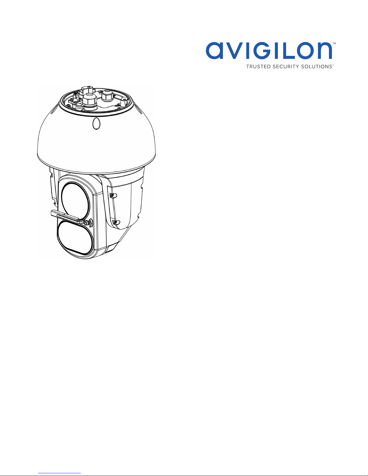
Installation Guide
Avigilon H4 PTZ Camera with IR Models:
1.0C-H4IRPTZ-DP45, 1.0C-H4IRPTZ-DP45-WP, 2.0C-H4IRPTZDP30 and 2.0C-H4IRPTZ-DP30-WP
Page 2
Important Safety Information
This manual provides installation and operation information and precautions for the use of this camera. Incorrect
installation could cause an unexpected fault. Before installing this equipment read this manual carefully. Please
provide this manual to the owner of the equipment for future reference.
This Warning symbol indicates the presence of dangerous voltage within and outside the product
enclosure that may result in a risk of electric shock, serious injury or death to persons if proper
precautions are not followed.
This Caution symbol alerts the user to the presence of hazards that may cause minor or moderate injury
to persons, damage to property or damage to the product itself if proper precautions are not followed.
WARNING — Failure to observe the following instructions may result in severe injury or death.
l This product should be installed by a trained professional and should be installed in restricted access
locations.
l This product is intended to be supplied by a UL Listed Power Unit marked“Class 2”or“LPS”or“Limited
Power Source”with output rated 24VAC±10%, 105 VA min.; 24VDC±10%, 75 W min.or a Microsemi PD9601G/AC Power over Ethernet (PoE) mid-span injector.
l Any external power supply connected to this product may only be connected to another Avigilon
product of the same model series. External power connections must be properly insulated.
l Do not connect directly to mains power for any reason.
l This product is intended to be used in a Network Environment 0 per IEC TR62101. The camera is to be
connected only to PoE networks that comply with IEEE 802.3at without routing to the outside plants.
CAUTION — Failure to observe the following instructions may result in injury to persons or damage to
the device.
l Do not install near any heat sources such as radiators, heat registers, stoves, or other sources of heat.
l Do not subject the device cables to excessive stress, heavy loads or pinching.
l Refer all device servicing to qualified personnel. Servicing may be required when the device has been
damaged (such as from a liquid spill or fallen objects), does not operate normally, or has been dropped.
l Do not use strong or abrasive detergents when cleaning the device body.
l Use only accessories recommended by Avigilon.
l This product should be installed in restricted access locations.
ii
Page 3
l Risk Group 1. NOTICE: IR emitted from this product. Use appropriate shielding or eye protection.
Regulatory Notices
This device complies with part 15 of the FCC Rules. Operation is subject to the following two conditions: (1)this
device may not cause harmful interference, and (2) this device must accept any interference received, including
interference that may cause undesired operation.
This Class B digital apparatus complies with Canadian ICES-003.
This equipment has been tested and found to comply with the limits for a Class B digital device, pursuant to Part
15 of the FCC rules. These limits are designed to provide reasonable protection against harmful interference in a
residential installation. This equipment generates, uses and can radiate radio frequency energy and, if not
installed and used in accordance with the instructions, may cause harmful interference to radio communications.
However, there is no guarantee that interference will not occur in a particular installation. If this equipment does
cause harmful interference to radio or television reception, which can be determined by turning the equipment
off and on, the user is encouraged to try to correct the interference by one or more of the following measures:
l Reorient or relocate the receiving antenna.
l Increase the separation between the equipment and the receiver.
l Connect the equipment into an outlet on a circuit different from that to which the receiver is connected.
l Consult the dealer or an experienced radio/TV technician for help.
Changes or modifications made to this equipment not expressly approved by Avigilon Corporation or parties
authorized by Avigilon Corporation could void the user’s authority to operate this equipment.
Disposal and Recycling Information
When this product has reached the end of its useful life, please dispose of it according to your local
environmental laws and guidelines.
Risk of fire, explosion, and burns. Do not disassemble, crush, heat above 100 °C (212 °F), or incinerate.
European Union:
This symbol means that according to local laws and regulations your product should be disposed of separately
from household waste. When this product reaches its end of life, take it to a collection point designated by local
iii
Page 4

authorities. Some collection points accept products for free. The separate collection and recycling of your
product at the time of disposal will help conserve natural resources and ensure that it is recycled in a manner
that protects human health and the environment.
Legal Notices
©2017,Avigilon Corporation. All rights reserved. AVIGILON, the AVIGILON logo, AVIGILONCONTROL
CENTER, ACC, and TRUSTED SECURITY SOLUTIONS are trademarks of Avigilon Corporation. ONVIFis a
trademark of Onvif, Inc. Other names or logos mentioned herein may be the trademarks of their respective
owners. The absence of the symbols ™ and ® in proximity to each trademark in this document or at all is not a
disclaimer of ownership of the related trademark. Avigilon Corporation protects its innovations with patents
issued in the United States of America and other jurisdictions worldwide (see avigilon.com/patents). Unless
stated explicitly and in writing, no license is granted with respect to any copyright, industrial design, trademark,
patent or other intellectual property rights of Avigilon Corporation or its licensors.
Disclaimer
This document has been compiled and published using product descriptions and specifications available at the
time of publication. The contents of this document and the specifications of the products discussed herein are
subject to change without notice. Avigilon Corporation reserves the right to make any such changes without
notice. Neither Avigilon Corporation nor any of its affiliated companies: (1) guarantees the completeness or
accuracy of the information contained in this document; or (2) is responsible for your use of, or reliance on, the
information. Avigilon Corporation shall not be responsible for any losses or damages (including consequential
damages) caused by reliance on the information presented herein.
Avigilon Corporation
avigilon.com
PDF-H4IRPTZ-DP-A
Revision: 1 - EN
20171204
iv
Page 5

Table of Contents
Overview 1
Rear View 1
Front View 2
Top View 3
Pendant Wall Mount View 4
NPT Mount View 5
Installation 6
Package Contents 6
Installation Steps 6
Installing the Mounting Adapter 6
Installing the Pendant Wall Mount 7
Installing the NPT Mount 8
Connecting Cables 9
Securing the PTZ Camera 12
(Optional) Configuring microSD Card Storage 13
Assigning an IP Address 13
Accessing the Live VideoStream 14
For More Information 14
Connecting to Power and External Devices 15
Setting the Home Preset Position 17
Manually Returning to the Home Position 17
Automatically Returning to the Home Position 17
Connection Status LED Indicator 18
Resetting to Factory Default Settings 19
Setting the IP Address Using the ARP/Ping Method 20
Cleaning 21
Lens and IR Window 21
Body 21
Specifications 22
Limited Warranty and Technical Support 24
v
Page 6
Overview
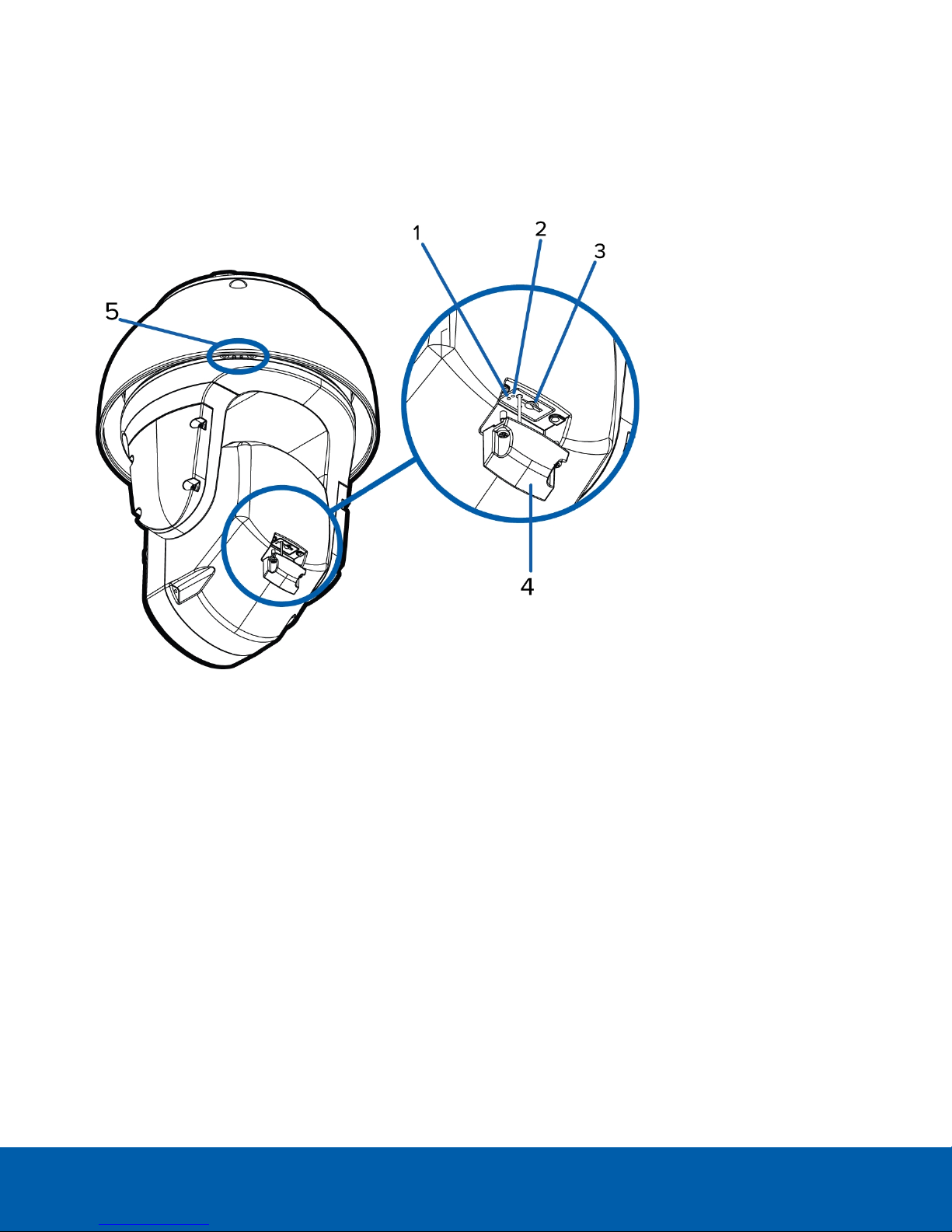
Rear View
1.
Link LED indicator
Indicates if there is an active connection in the Ethernet port.
2.
Connection status LED indicator
Provides information about device operation. For more information, see Connection Status LED Indicator
on page18.
3.
microSD card slot
Accepts a microSD card for onboard storage.
4.
microSD cover
Protective cover for the microSD card slot. Uses tamper resistant screws to secure the cover.
5.
Sprayer mounting location
(Available on -WP models only.) An optional washer can be mounted at this location for cleaning the lens
and IR window. The washer and cleaning liquid are sold separately.
Install the sprayer mounting bracket by tightening the provided screws into this location.
Overview 1
Page 7
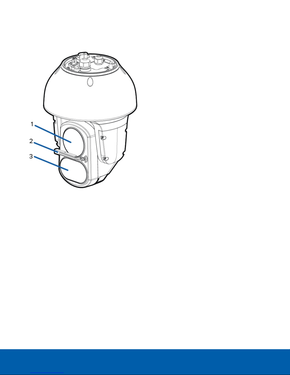
Front View
1.
Lens
The camera lens is housed behind a protective window.
2.
Wiper
(Available on -WP models only) Wiper rotates 90° in both directions to clean both lens and IR window.
3. Variable IR Illuminators
High powered infrared LEDs with variable field of view to accommodate different low light situations.
The IR illuminators are housed behind a protective window.
Front View 2
Page 8
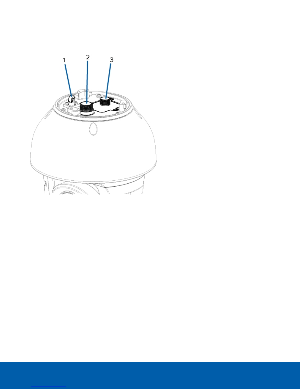
Top View
1.
Lanyard anchor
The safety lanyard attaches to the anchor to prevent the camera from falling during installation.
2.
Ethernet port
Accepts an Ethernet connection to a network. Server communication and image data transmission occurs
over this connection. Also receives power when it is connected to a network that provides Power over
Ethernet.
3.
Power and I/O cables
Cables for connecting the camera to auxiliary power and I/O devices. For more information, see
Connecting to Power and External Devices on page15.
Top View 3
Page 9
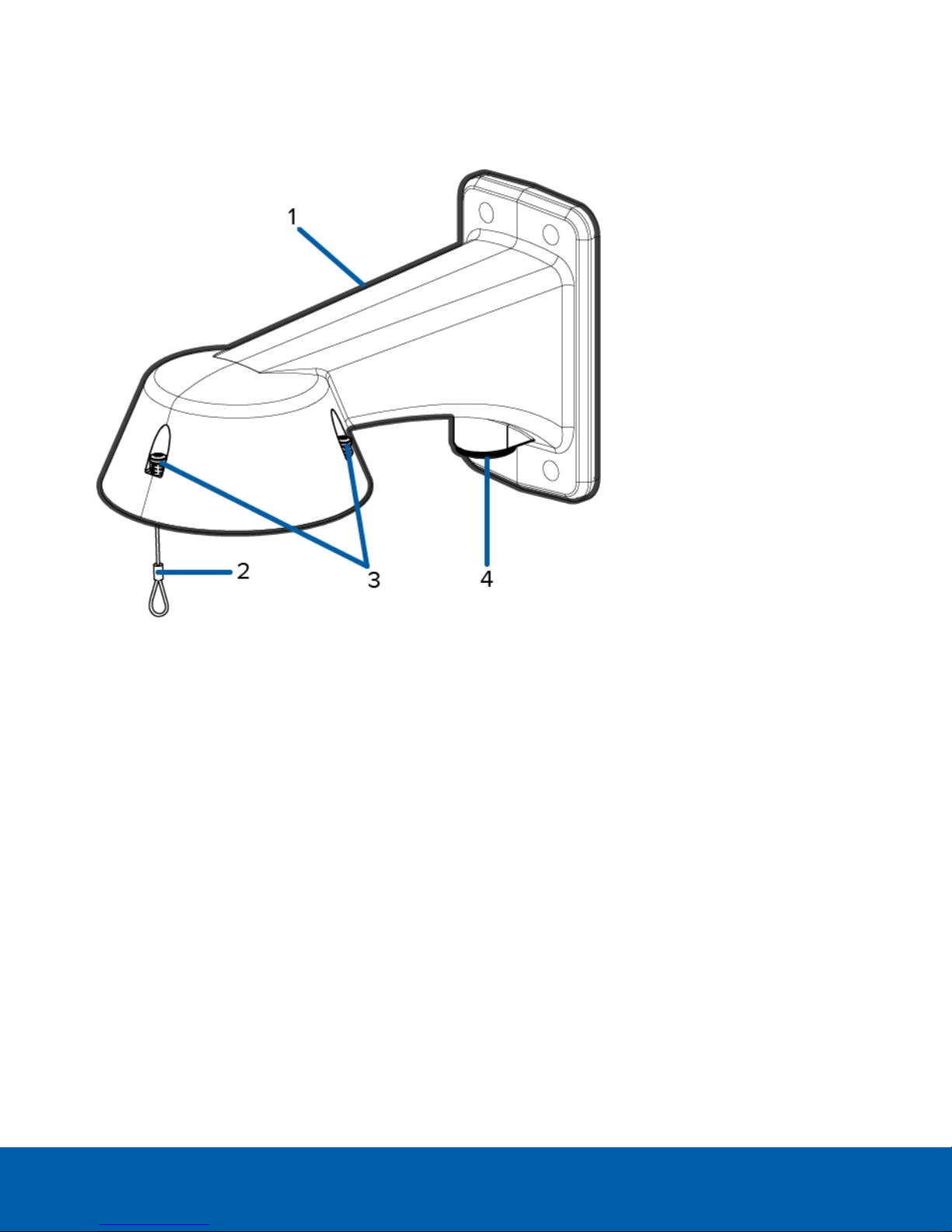
Pendant Wall Mount View
1.
Pendant wall mount
Camera mount for walls and other mounting surfaces.
2.
Lanyard
Connects to the lanyard anchor on the camera base.
3.
Tamper resistant screws
Star captive screws to fix the dome camera to the mounting adapter.
4.
NPT pipe entry hole
A 3/4” NPT threaded hole for NPT pipe conduits.
Pendant Wall Mount View 4
Page 10

NPT Mount View
1.
1-1/2” NPT-female to NPT-female adapter
An adapter for attaching the pendant NPT mount to an NPT pipe.
NOTE: The adapter is not an included accessory supplied by Avigilon and should be sourced separately.
2.
Lock nut
Locking nut for securing the pendant NPT mount on the NPT-female to NPT-female adapter.
3.
Pendant NPT mount
Dome camera mount for NPT pipes.
4.
Lanyard
Connects to the lanyard anchor on the camera base.
5.
Tamper resistant screws
Star captive screws to fix the dome camera to the mounting adapter.
NPT Mount View 5
Page 11

Installation
Package Contents
NOTE: The pendant wall mount and pendant NPT mount are sold separately.
Ensure the camera package contains the following:
l Avigilon H4 IR PTZ Camera
l T20 star key
l T10 star key
l 3 x RJ-45 crimp-on plug
l External power and I/O wiring harness
l Sprayer mounting bracket and installation screws (only for models with wiper)
If you are installing the camera with the pendant wall mount, ensure the package includes the following:
l Pendant wall mount (H4IRPTZ-MT-WALL1 )
l Mounting template sticker
If you are installing the camera with the NPT mount, ensure the package includes the following:
l NPT mount (H4IRPTZ-MT-NPTA1)
l Lock nut
l Thread sealing tape
Installation Steps
Complete the following sections to install the device.
Installing the Mounting Adapter
The PTZcamera can only be mounted to a pendant wall mount (H4IRPTZ-MNT-WALL1) or a pendant NPT mount
(H4IRPTZ-MNT-NPTA1). The mounts are sold separately.
Use the pendant wall mount if you will be mounting the camera to a vertical mounting surface such as a wall.
Use the pendant NPT mount if you will be mounting the camera to a 1-1/2” NPT pipe for a free hanging
installation.
Installation 6
Page 12

Installing the Pendant Wall Mount
1. Determine where the cable will enter the pendant wall mount.
l If the cable will be pulled from inside the mounting surface, use the cable entry hole at the rear of
the pendant wall mount.
l If the cable will be coming out of an external conduit pipe, use the 3/4” NPT pipe entry hole on the
bottom of the pendant wall mount.
2. Use the provided mounting template to drill four mounting holes into the mounting surface.
l If you are using the rear cable entry hole, also drill the cable entry hole into the mounting surface.
3. Pull the required cables through the preferred cable entry hole on the pendant wall mount.
l If you are using the pipe entry hole, pull the cables through the pipe conduit then the wall mount.
Next, apply thread seal tape to the pipe conduit and screw it into the pipe entry hole.
Figure 1: Cables pulled from the back entry h ole. Figure 2: Cables pulled from th e condu it entry h ole.
4. Fasten the pendant wall mount to the mounting surface.
Installing the Pendant Wall Mount 7
Page 13

5. Tighten the wall mount screws to secure the wall mount to the wall.
6. Connect the safety lanyard from inside the wall mount to the anchor on the PTZ camera.
Installing the NPT Mount
NOTE: This procedure requires a 1-1/2” NPT-female to NPT-female pipe adapter. It is recommended that the
NPT adapter be mounted to a 1-1/2” conduit pipe.
1. Pull the required cable through the NPT conduit pipe.
2. Apply thread seal tape to the pipe and screw on the 1-1/2” NPT female to NPT female pipe adapter.
3. Screw the lock nut onto the NPT adapter.
4. Apply thread seal tape to the NPT adapter and screw it into the pipe adapter.
Make sure the parts are assembled in this order from NPT conduit pipe to camera adapter:
a. NPT conduit pipe
b. 1-1/2" NPT female to female pipe adapter
c. Lock nut
d. NPT adapter
Installing the NPT Mount 8
Page 14

5. Connect the safety lanyard from inside the NPT mount to the anchor on the PTZ camera.
Connecting Cables
Refer to the diagrams in the Overview section for the location of the different connectors.
To connect the cables required for proper operation, complete the following:
NOTE: The PTZcamera does not support cables with boots and strain reliefs.
ConnectingCables 9
Page 15

1. Make sure the safety lanyard is connected to the camera.
2. Remove the sealing gland caps from the top of the camera.
3. If there are external input or output devices that need to be connected to the camera (for example: door
contacts, relays, analog video, speakers, etc.), connect the devices to the camera I/O connector cable.
4. Connect power using one of the following methods:
l 95W PoE Injector (POE-INJ2-95W) — Connect an Ethernet network cable to the injector.
l External Power — Connect a 24V DC or 24V AC (RMS) auxiliary power source that supports up to
75 W or 105VA.
For more information, see Connecting to Power and External Devices on page15.
5. Feed the network cable through the gland cap and cable gland.
ConnectingCables 10
Page 16

6. Remove the I/O cover and feed the I/O connector cable through the gland cap, cable gland, and I/O
cover.
7. Tighten the cable glands around the cables.
8. Connect power and I/O to the camera, then tighten the I/O cover.
9. Connect a network cable to the Ethernet port (RJ-45 connector).
The Link LED indicator will turn on once a network link has been established.
NOTE: If you need to remove the RJ45 connector from the camera to check a network issue, gently pull
the cable towards the locking tab to release the RJ45 plug before pulling upwards.
10. Check that the Connection Status LED indicator indicates the correct state. For more information, see
Connection Status LED Indicator on page18.
ConnectingCables 11
Page 17

Securing the PTZ Camera
1. Push the PTZ camera into the mount adapter.
NOTE: Be careful not to trap any cables between the camera housing and the mount adapter.
Figure 3: Pushing the camerainto the wall mount adapter. Figure 4: Pushing the camera into the NPT adapter.
2. Once the camera housing is aligned to the adapter, turn the camera until it locks into place.
3. Use the T20 star key to tighten the screws in the mount adapter.
Figure 5: Secu ring the camerato the wall mount adapter. Figure 6: Secu ring the camerato the NPT adapter.
Securing the PTZCamera 12
Page 18

4. If you are installing the camera to an NPT mount, make sure the mount adapter is secured then tighten the
lock nut to fix the camera to its final position.
(Optional) Configuring microSD Card Storage
To use the camera's microSD card storage feature, you must insert a microSD card into the card slot.
It is recommended that the microSD card have a capacity of 8GB or more and a write speed of class 6 or better.
If the SD card does not meet the recommended capacity or write speed, the recording performance may suffer
and result in the loss of frames or footage.
1. Using the T10 star Key, unscrew and open the microSD cover at the rear of the camera.
For more information about the location of the rear cover and the microSD card slot, see Rear View on
page1.
2. Insert a microSD card into the camera.
CAUTION — Do not force the microSD card into the camera or you may damage the card and the
camera.
3. Access the camera’s web interface to enable the onboard storage feature. For more information, see the
Avigilon High Definition H.264 Camera Web Interface User Guide.
Assigning an IP Address
The device automatically obtains an IP address when it is connected to a network.
NOTE: If the device cannot obtain an IP address from a DHCP server, it will use Zero Configuration Networking
(Zeroconf) to choose an IP address. When set using Zeroconf, the IP address is in the 169.254.0.0/16 subnet.
The IP address settings can be changed using one of the following methods:
l Device's web browser interface: http://<camera IP address>/.
l Network Video Management software application (for example, the Avigilon Control Center™ software).
l ARP/Ping method. For more information, see Setting the IP Address Using the ARP/Ping Method on
page20.
NOTE: The default device username is administrator with no password.
(Optional) Configuring microSDCard Storage 13
Page 19

Accessing the Live VideoStream
Live video stream can be viewed using one of the following methods:
l Web browser interface: http://< camera IP address>/.
l Network Video Management software application (for example, the Avigilon Control Center software).
NOTE: The default camera username is administrator with no password.
For More Information
Additional information about setting up and using the device is available in the following guides:
l Avigilon Control Center Client User Guide
l Avigilon High Definition H.264 Web Interface User Guide
l Avigilon Camera Configuration Tool User Guide
These guides are available on the Avigilon website: avigilon.com/support-and-downloads.
Accessing the LiveVideoStream 14
Page 20

Connecting to Power and External Devices
CAUTION — Be careful to only connect power to the Auxiliary Power Wires or the camera will be
damaged.
If PoE is not available, the camera may be powered through the auxiliary power cable using either 24V DC or
24V AC. The power consumption information is listed in the product specifications.
To power the camera, connect the two power wires to the red and black auxiliary power wires. The connection
can be made with either polarity.
WARNING — This product is intended to be powered by a UL Listed Power Unit marked “Class 2” or
“LPS” or “Limited Power Source” with output rated 24 V AC +/- 10%, 105 VA min. or 24 V DC +/- 10%,
75W min.
Power supplies and external devices are connected to the camera through the power and I/O wires. The pinout
for the I/O and power wires is shown in the following diagram:
Figure 7: Example application.
1. Pink (AUDIO_IN) — Audio Input (line level)
An external power amplifier should be used when connecting speakers and microphones, as shown in
the diagram.
1. Black — Audio Ground
2. Light Green (AUDIO_OUT)— Audio Output (line level)
2. Black — Audio Ground
3. Light Blue (GND) — Ground for digital inputs and outputs.
Connectingto Power and External Devices 15
Page 21

4. Yellow (RI_1)— Digital Input, Relay 1. The input voltage must be below 0.7V to register as a low input. The
input voltage should not exceed 5V when high.
5. Orange (RI_2)— Digital Input, Relay 2
6. Light Green (RI_3)— Digital Input, Relay 3
7. Brown (RI_4) — Digital Input, Relay 4
8. Purple (RO+)— +5V power output from camera. For the maximum allowable current, see Specifications on
page22.
9. Blue (RO_1) — Digital Output,
10. Green (RO_2) — Digital Output
11. Pink (Reserved) — Reserved Wire, do not connect.
12. Red (DC) — Auxiliary Power Wire, accepts DC and AC power.
13. Black (DC) — Auxiliary Power Wire, accepts DC and AC power.
l 1 — External relay power supply
l 2 — Optional 24 V AC (RMS) or 24 V DC Aux. power supply
Connectingto Power and External Devices 16
Page 22

Setting the Home Preset Position
The PTZ camera supports self-learning video analytics from the home preset position. The home preset position
is typically the field of view the PTZ camera returns to after being used for investigations.
Before you can configure the camera's home position, you must connect the camera to a site in the ACC™ Client
software. For more information about adding cameras to a site and the following steps, see the Avigilon Control
Center Client User Guide.
To set the home preset position, display the live video from the PTZ camera then complete the following steps:
Tip: Name the preset position "Home" so that it will be easy to find when configuring the camera for other
applications.
1. Move the camera's field of view into position.
2.
In the Presets drop down list, select a number then click .
3. In the dialog box, enter a name for the preset.
4. Select the Set as home preset check box if you want this to be the camera's Home preset.
5. Click OK.
After you've set the camera's home preset position, you can configure the required video analytics events in the
ACC Client software.
Manually Returning to the Home Position
After the home preset position has been configured, you can set the PTZ camera to return to the configured
field of view by clicking .
Automatically Returning to the Home Position
You can also configure the PTZ camera to automatically return to the home preset position after the camera is
left idle for a set amount of time. This can be configured in two ways: through a PTZ tour or a rule.
A PTZ tour can be configured from the camera web interface or in the ACC Client software. To configure the
PTZ camera to automatically return to the home position, create a new tour and add only the home position to
the preset list. Next, select the Set as default tour check box and use the Default Tour Idle Start Time (Minutes)
field to define the expected amount of idle time before the camera returns to the home position.
To use the rule method, you must have an Enterprise Edition or Standard Edition version of the Avigilon Control
Center system. To configure the PTZ camera to automatically return to the home position, create a rule that
includes the following settings:
l On the Select Rule Event(s) page, select PTZ idle.
l On the Select Rule Action(s) page, select Go to Home Preset.
Setting the Home Preset Position 17
Page 23

Connection Status LED Indicator
Once connected to the network, the Connection Status LED indicator will display the progress in connecting to
the Network Video Management software.
The following table describes what the LED indicator shows:
Connection State
Obtaining IPAddress
Discoverable
Upgrading Firmware
Connected On
Connection Status
One short flash every
second
Two short flashes
every second
Two short flashes
and one long flash
every second
LED Indicator
Description
Attempting to obtain an IP address.
Obtained an IPaddress but is not connected to the
NetworkVideo Management software.
Updating the firmware.
Connected to the Network Video Management software or an
ACC™ Server. The default setting can be changed to "Off" using
the camera's web user interface. For more information see the
Web Interface User Guide - H4 HD.
Connection Status LED Indicator 18
Page 24

Resetting to Factory Default Settings
If the device no longer functions as expected, you can choose to reset the device to its factory default settings.
Use the firmware revert button to reset the device. The firmware revert button is shown in the following diagram:
Figure 8: The firmware revert button below the SD card slot.
1. Ensure the camera is powered on.
2. Use the T10 star key to remove the SD cover.
3. Using a straightened paperclip or similar tool, gently press and hold the firmware revert button for two
seconds.
4. Re-install the SD cover.
CAUTION — Do not apply excessive force. Inserting the tool too far will damage the camera.
Resetting to Factory Default Settings 19
Page 25

Setting the IP Address Using the ARP/Ping Method
Complete the following steps to configure the camera to use a specific IP address:
NOTE: The ARP/Ping Method will not work if the Disable setting static IP address through ARP/Ping method
check box is selected in the camera's web browser interface. For more information, see the Web User Interface
Guide - Avigilon High Definition H.264 IP Camera Models.
1. Locate and copy down the MAC Address (MAC) listed on the Serial Number Tag for reference.
2. Open a Command Prompt window and enter the following commands:
a. arp -s <New Camera IP Address> <Camera MAC Address>
For example: arp -s 192.168.1.10 00-18-85-12-45-78
b. ping -l 123 -t <New Camera IP Address>
For example: ping -l 123 -t 192.168.1.10
3. Reboot the camera.
4. Close the Command prompt window when you see the following message:
Reply from <New Camera IP Address>: ...
Setting the IP Address Using the ARP/Ping Method 20
Page 26

Cleaning
Lens and IR Window
If the video image becomes blurry or smudged in areas, it may be because the lens or IR window requires
cleaning.
NOTE: Washer and cleaning liquid sold separately.
To clean the camera windows:
l In the camera web interface or video management software, activate the washer and wiper.
l From the camera web interface, the washer and wiper can be activated from the Live View page.
For more information, see the Avigilon High Definition H.264 Web Interface User Guide.
l From the Avigilon Control Center software, the washer and wiper is activated through the PTZ
auxiliary command. For more information, see the software help files.
If the cleanliness of the camera window continues to affect the imaging quality, or if you are maintaining a model
that does not have a wiper, manually clean the camera windows as needed:
l Use hand soap or a non-abrasive detergent to wash off dirt or fingerprints.
l Use a microfiber cloth or non-abrasive fabric to dry the dome bubble.
CAUTION — Failure to use the recommended cleaning materials may result in a damaged or scratched
camera window. A damaged camera window may negatively impact image quality and cause unwanted
IR light reflecting into the lens.
Important: Failure to use the recommended cleaning materials may result in a damaged or scratched camera
window. A damaged camera window may negatively impact image quality and cause unwanted IR light
reflecting into the lens.
Body
l Use a dry or lightly dampened cloth to clean the camera body.
l Do not use strong or abrasive detergents.
Cleaning 21
Page 27

Specifications
Camera
Lens 4.3 to 129mm, F/1.6 – F/4.7, autofocus
Audio Input/Output Line level input and output
microSD Storage
Network
Network 100Base-TX
Cabling Type CAT5
Connector RJ-45
API
Device Management
Protocols
Security
Streaming Protocols
Mechanical
microSD/microSDHC/microSDXC slot – minimum class 6; class 10/UHS-1 or better
recommended
ONVIF® compliant version 1.02, 2.00, Profile S (www.onvif.org)
Compliant with version 2.2.0 of the Analytics Service Specification (bounding boxes and
scene descriptions not available with third-party VMS)
SNMP v2c
SNMP v3
Password protection, HTTPS encryption, digest authentication, WS authentication, user
access log, 802.1x port based authentication.
IPv4, HTTP, HTTPS, SOAP, DNS, NTP, RTSP, RTCP, RTP, TCP, UDP, IGMP, ICMP, DHCP,
Zeroconf, ARP, RTP/UDP, RTP/UDP multicast, RTP/RTSP/TCP, RTP/RTSP/HTTP/TCP,
RTP/RTSP/HTTPS/TCP, HTTP
Dome camera — (Ø) 250 mm x (H) 364 mm; (Ø) 9.84” x (H) 14.33”
Dimensions
Weight
Windows Glass
Body Aluminum
Housing Pendant mount
Finish Powder coat, RAL 9003
Tilt -20° to 90°, 300° / second max.
Pan 360°, endless, 300° / second max.
Electrical
Power Consumption 75 W max
With wall mount — (W) 363 mm x (L) 250 mm x (H) 457 mm; (W) 14.29” x (L) 9.84” x (H)
17.99"
With NPT mount — (Ø) 250 mm x (H) 444 mm; (Ø) 9.84” x (H) 17.48”
Dome camera — 6.66 kg; 14.68 lbs
With wall mount — 7.77 kg; 17.13 lbs
With NPT mount — 7.13 kg; 15.72 lbs
Specifications 22
Page 28

105 VA with 24 V AC power
V DC: 24 V +/- 10%
Power Source
V AC: 24 Vrms +/- 10%, 50 or 60Hz
PoE: 95 W PoE (POE-INJ2-95W)
Power Connector Wire leads
RTC Backup Battery 3V manganese lithium
Environmental
Operating
Temperature
Storage
Temperature
-40°C to +60°C (-40 °F to 140 °F) with external power or 95W PoE
-10 °C to +70 °C (14 °F to 158 °F)
Humidity 0-95% non-condensing
Certifications
Certifications UL, cUL, CE, ROHS, WEEE, RCM
Safety UL 62368-1, CSA 62368-1, IEC/EN 62368-1
IK10 Impact Rating (camera body only)
Environmental
IEC 60529 IP66 Weather Rating
IEC/UL/CSA 60950-22
FCC Part 15 Subpart B Class B
IC ICES-003 Class B
Electromagnetic
Emissions
EN 55032 Class B
EN 61000-6-3
EN 61000-3-2
EN 61000-3-3
Electromagnetic
Immunity
EN 55024
EN 61000-6-1
Specifications 23
Page 29

Limited Warranty and Technical Support
Avigilon warranty terms for this product are provided at avigilon.com/warranty.
Warranty service and technical support can be obtained by contacting Avigilon Technical Support:
avigilon.com/contact-us/.
Limited Warranty and Technical Support 24
 Loading...