

Avigilon 10.0TB-HD-NVR-EC2, 5.0TB-HD-NVR-LPR, 15.0TB-HD-NVR, 15.0TB-HD-NVR-LPR, 15.0TB-HD-NVR-EC2 Installation Manual
...
Installation Guide
Avigilon High Definition Network Video Recorder Server:
2.5TB-HD-NVR, 2.5TB-HD-NVR-LPR
5.0TB-HD-NVR, 5.0TB-HD-NVR-LPR
10.0TB-HD-NVR, 10.0TB-HD-NVR-LPR, 10.0TB-HD-NVR-EC2
15.0TB-HD-NVR, 15.0TB-HD-NVR-LPR, 15.0TB-HD-NVR-EC2
920-0047A-Rev1

Copyright © 8/30/11 Avigilon. All rights reserved.
No copying, distribution, publication, modification, or incorporation of this
document, in whole or part, is permitted without the express written
permission of Avigilon. In the event of any permitted copying, distribution,
publication, modification, or incorporation of this document, no changes in
or deletion of author attribution, trademark legend, or copyright notice
shall be made. No part of this document may be reproduced, stored in a
retrieval system, published, used for commercial exploitation, or
transmitted, in any form by any means, electronic, mechanical,
photocopying, recording, or otherwise, without the express written
permission of Avigilon.
Dell, PowerEdge R710, OpenManage Server Administrator and their
images are registered trademarks of Dell.
Microsoft and Windows XP are registered trademarks of Microsoft
Corporation.
Avigilon has made every effort to identify trademarked properties and
owners on this page. All brands and product names used in this
document are for identification purposes only and may be trademarks or
registered trademarks of their respective companies.
Avigilon
Tel +1.604.629.5182
Fax +1.604.629.5183
http://www.avigilon.com
Revised 27/09/2011

English
Table of Contents
Overview . . . . . . . . . . . . . . . . . . . . . . . . . .1
Front . . . . . . . . . . . . . . . . . . . . . . . . . . . . . . . . . 1
Back . . . . . . . . . . . . . . . . . . . . . . . . . . . . . . . . . 2
Installation . . . . . . . . . . . . . . . . . . . . . . . .3
Required Tools and Materials . . . . . . . . . . . . . . 3
Package Contents . . . . . . . . . . . . . . . . . . . . . . . 3
Installation Steps . . . . . . . . . . . . . . . . . . . . . . . . 3
Installing the Rack Rails and Cable
Management Arm. . . . . . . . . . . . . . . . . 4
Connecting Cables . . . . . . . . . . . . . . . . 4
Installing the Bezel . . . . . . . . . . . . . . . . 4
Licensing the Avigilon Control Center . . 5
Assigning an IP Address . . . . . . . . . . . . 8
Advanced Features . . . . . . . . . . . . . . . . .9
Server Administrator . . . . . . . . . . . . . . . . . . . . . 9
Connecting Storage Expansions . . . . . . . . . . . 10
Replacing Hard Drives . . . . . . . . . . . . . . . . . . 11
LED Indicators . . . . . . . . . . . . . . . . . . . .14
Power Status Indicators . . . . . . . . . . . . . . . . . 14
Network Link Status Indicator . . . . . . . . . . . . . 15
Hard Drive RAID Status Indicators . . . . . . . . . 16
Specifications . . . . . . . . . . . . . . . . . . . . .17
Limited Warranty & Technical Support 18

English
1
English
Overview
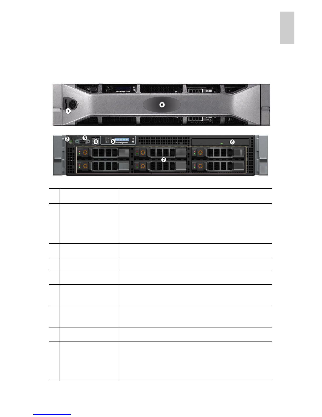
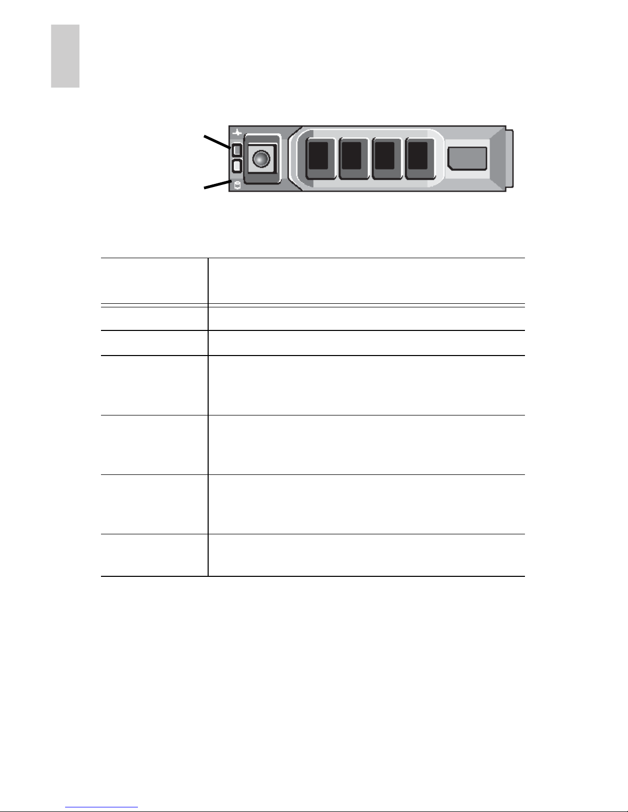
Front
Feature Description
0
Bezel The bezel protects the server from
unauthorized physical access. The bezel
must be removed to access the front of the
server.
1
Bezel lock Locks the bezel into place.
2
Power button Controls the power supply to the server.
3
Video connector Accepts a monitor connection.
4
USB connectors Accepts USB connections to external
devices.
5
LCD message
display
Displays server status information and error
messages.
6
DVD drive Provides access to DVD media.
7
Hard drives Provides access to six hot-swappable hard
drives. There are LED indicators on each
hard drive. See LED Indicators on page 14
for more information.

2
English
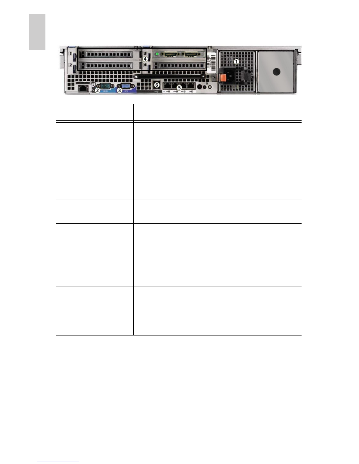
Back
Feature Description
1
Power supply Accepts power input.
A secondary redundant power supply
(HD-NVR-2ND-PS) can be installed in the
space on the right.
2
Serial connector Accepts connections to serial devices.
3
Video connector Accepts a VGA monitor connection.
4
Expansion slots There are 4 empty expansion slots that can
be used to connect to external storage
expansions.
For server models x.xTB-NVR-EC2, an
Avigilon NVR Expansion Card is
preinstalled (as shown in the image).
5
Ethernet port Accepts an Ethernet connection to a
network.
6
USB connectors Accepts USB connections to external
devices.

3
English
Installation
Required Tools and Materials
• #1 Phillips screwdriver
Package Contents
Ensure the package contains the following:
• Avigilon High Definition Network Video Recorder (NVR)
Server
• Avigilon Control Center Software Installation DVD
• Avigilon Control Center Recovery DVD
• Power Cable
• USB Keyboard
• USB Mouse
• Bezel and Key
• Rack Sliding Rail Assembly Kit
• Cable Management Arm Assembly Kit
Installation Steps
Consult the Product Information Guide provided with the server for
relevant safety information before you begin installation.
• Installing the Rack Rails and Cable Management Arm on
page 4
• Connecting Cables on page 4
• Installing the Bezel on page 4
• Licensing the Avigilon Control Center on page 5
• Assigning an IP Address on page 8

4
English
Installing the Rack Rails and Cable
Management Arm
If the server will be kept in a server rack, install the Rack Sliding
Rails and the Cable Management Arm provided in the server
package. Follow the procedures outlined in the Rack Installation
Instructions and the CMA Installation Instructions provided in the
assembly kits.
The included mounting rails are designed for racks with square
holes. If you require rails for round hole racks (HD-NVR-RAILSRND), contact your local Avigilon Sales Representative.
Connecting Cables
Refer to the server diagrams in the Overview section for the
location of the different connectors.
1. Connect the keyboard and mouse to an available USB
connector on either the front or the back of the server.
2. Connect a monitor to the video connector on the front of the
server.
3. Connect the server to your network using an Ethernet
network cable.
4. Connect the power cable to the power supply at the back of
the server.
5. If you are also installing an Avigilon HD NVR Storage
Expansion with your server, connect the server to the
storage expansion. See Connecting Storage Expansions
on page 10 for more information.
6. Press the power button on the front of the server. Check
that the server LED indicators display the correct status.
See LED Indicators on page 14 for more information.
Installing the Bezel
The bezel can be installed on the front of the server to help protect
the power button and hard drives against unauthorized access.
5
English
1. Slide the right end of the bezel against the right hinge of the
server.
2. Push the left end of the bezel against the server until it
clicks into place.
3. Use the provided key to lock the bezel.
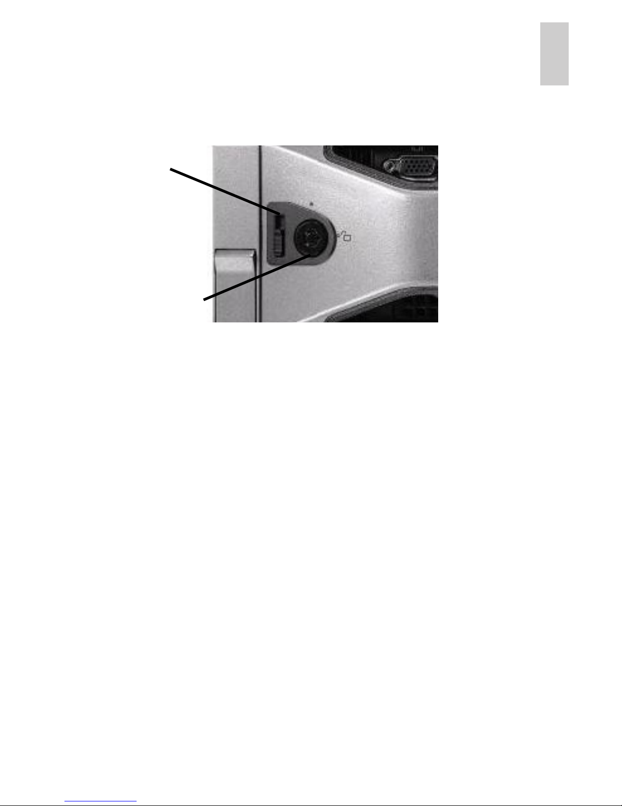
Removing the Front Bezel
The bezel must be removed before you can access the power
button, hard drives, and DVD drive.
1. Unlock the bezel.
2. Pull the release latch beside the bezel lock, then carefully
pull the bezel away from the server.
Licensing the Avigilon Control Center
Once the server has been installed, you need to activate the
license for the Avigilon Control Center Server software before it can
be used to coordinate your high definition surveillance system.
NOTE: If the Control Center Server software was not preinstalled,
insert the installation DVD and install the software.
1. Log in to Windows.
The default username is
Administrator with no password.
2. Open the Admin Tool:
Bezel Lock
Release
Latch

6
English
• From the Windows Start menu, select Programs >
Avigilon > Avigilon Control Center Server >
Avigilon Control Center Server Admin Tool.
• Or, double-click the icon on your desktop.
3. When the Avigilon Control Center Admin Tool opens, select
the Settings tab and click Licensing.
4. In the License Activation dialog box, click Add License.
The Add License wizard is displayed.
You have two license activation options: Internet Activation
or Manual Activation. Complete one of the following
procedures.
Internet Activation
If you have internet access on your server, the Admin Tool
connects to the internet and activates your license.
1. In the Add License wizard, click Internet Activation.
2. On the Enter Product Key page, enter your license key.
A green check mark will appear beside your license key
when it is correct.
3. Click Next.
4. On the Product Registration page, enter your contact
information to receive product updates. Then click Next.
5. The Admin Tool connects to the Avigilon licensing server
and activates the license.
When the Activation Succeeded message appears, click
Finish.
Manual Activation
If your server does not have internet access, you can activate your
license by generating an activation file from the Admin Tool and
uploading the file to the Avigilon License Activation web page from
a computer with internet access.

7
English
1. In the Add License wizard, click Manual Activation.
2. On the following page, click Step 1: Generate Activation
File.
3. On the Enter Product Key page, enter your license key.
A green check mark will appear beside your license key
when it is correct.
4. Click Next.
5. On the Select Activation File page, confirm where the
activation file will be saved. Click [...] to navigate to a
different file location.
You can rename the activation file, but you must keep the
.key extension.
6. Click Next.
On the following page, you will see the Activation File
Saved message.
7. Find the saved activation file and copy the file to a computer
with internet access.
8. Open a web browser and go to
http://activate.avigilon.com
.
9. At the Avigilon License Activation web page, click Browse
to locate your activation file then click Upload Activation
File.
10.When you see the You have successfully activated your
product! message, click Download License File and save
the license file.
11.Complete the product registration section to receive
product updates from Avigilon, then click Register.
12.Find the downloaded license file and copy the file to the
server you are activating.
13.If the Activation File Saved message is still displayed in the
Add License wizard, click Next.
14.On the following page, click Step 2: Add License File.
15.On the Import License File page, click [...] to locate the
license file then click Next.

8
English
16.When the Activation Succeeded message appears, click
Finish.
Assigning an IP Address
Once the Avigilon Control Center Server has been licensed, you
can assign an IP address to the server. The server obtains an IP
address automatically by default, but you can configure the server
to use a static IP address.
1. In Windows, select Start > Control Panel > Network
Connections.
2. Right-click a network connection and select Properties.
3. In the Local Area Connection Properties dialog box, select
Internet Protocol (TCP/IP) then click Properties.
4. In the Internet Protocol (TCP/IP) Properties dialog box, you
can allow the server to obtain an IP address automatically,
or you can choose to assign a static IP address:
a. Select Use the following IP address: then assign an
IP address, a Subnet mask, and a Default gateway.
b. Enter the Preferred DNS server address and an
Alternate DNS server address.
c. Click OK.
5. Click OK to close the Local Area Connection Properties
dialog box.
9
English
Advanced Features
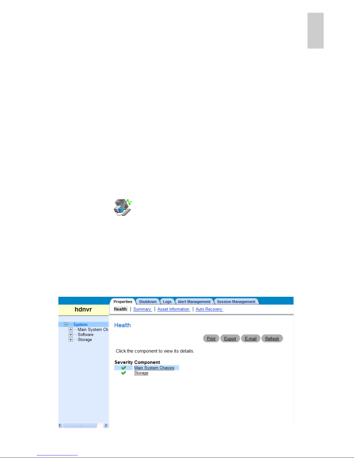
Server Administrator
The Server Administrator software is preinstalled on the server.
The software provides information about the server’s system
operation status, and gives you remote access to the server for
recovery operations.
If one of the LED indicators on the server is flashing an error
warning, the Server Administrator will display details about the
problem. For more information about the LED indicators, see LED
Indicators on page 14.
1. Open the Server Administrator.
• To open the Server Administrator locally, double-click
the Server Administrator shortcut icon on the
desktop.
• To open the Server Administrator remotely, open a
web browser and enter this address: http://<server
IP Address>:1311/
(for example,
http://192.168.1.32:1311/)
2. On the Server Administrative home page, the health of the
system components are displayed in the workspace on the
right.
10
English
• To see the health of other system components, expand
and select a different component from the System Tree
on the left.
• The table displayed in the workspace lists system
components and their status.
• To see the details of a system component, select the
system component from the workspace.
3. Select System on the System Tree to return to the home
page.
For more information about the features in the Server
Administrator, see the Help system provided in the software.
Connecting Storage Expansions
To increase the recording capacity of your Avigilon HD Surveillance
System, you can connect an Avigilon HD NVR Storage Expansion
(HD-NVR-EXP2-x.xTB) to the server.
NOTE: The Avigilon HD NVR server must have an Avigilon NVR
Expansion Card (HD-NVR-EXP2-CARD) installed before
the storage expansion can be connected. Be aware that
server models x.xTB-NVR-EC2 have the expansion card
preinstalled.
1. Connect power to the storage expansion. Ensure the server
is turned off.
2. Connect the storage expansion to the server.
a. Connect one end of the supplied Serial Attached SCSI
(SAS) cable to the storage expansion’s primary In port.
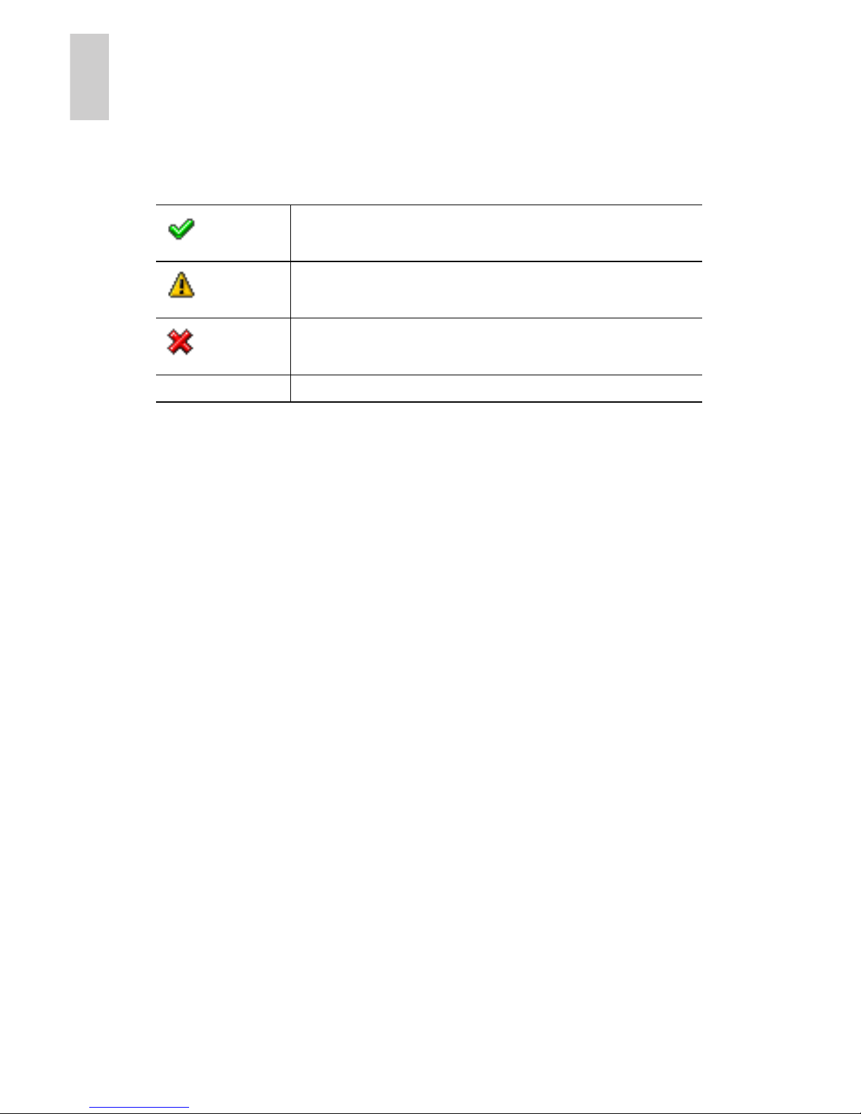
The system component is running normally.
The system component has an error.
The system component has a critical failure.
No symbol
The system component status is unknown.

11
English
b. Connect the other end of the SAS cable to an available
port on the expansion card installed on the back of the
server.
3. Turn on the storage expansion and the server.
4. In the Admin Tool, set up the Avigilon Control Center
storage configuration to include the storage expansion.
For more information, see Connecting the NVR Expansion that is
provided with the storage expansion.
Replacing Hard Drives
The hard drives on the server are set up in a Redundant Array of
Independent Disks (RAID) configuration. This allows information to
be recorded across several hard drives. If one hard drive fails,
there is enough information on the other hard drives for the server
to continue functioning. The server contains six hot-swappable
hard drives that can be replaced while the server is running. Only
one hard drive can be replaced at a time while the server is
running.
If your server is still under warranty, contact Avigilon Technical
Support to replace a failed hard drive:
http://avigilon.com/support/
If two or more hard drives fail at the same time, contact Avigilon
Support immediately for recovery instructions.
Important:
Only replace a hard drive if the hard drive LED
indicator and the Server Administrator displays an error. See
LED Indicators on page 14 and Server Administrator on
page 9 for more information.
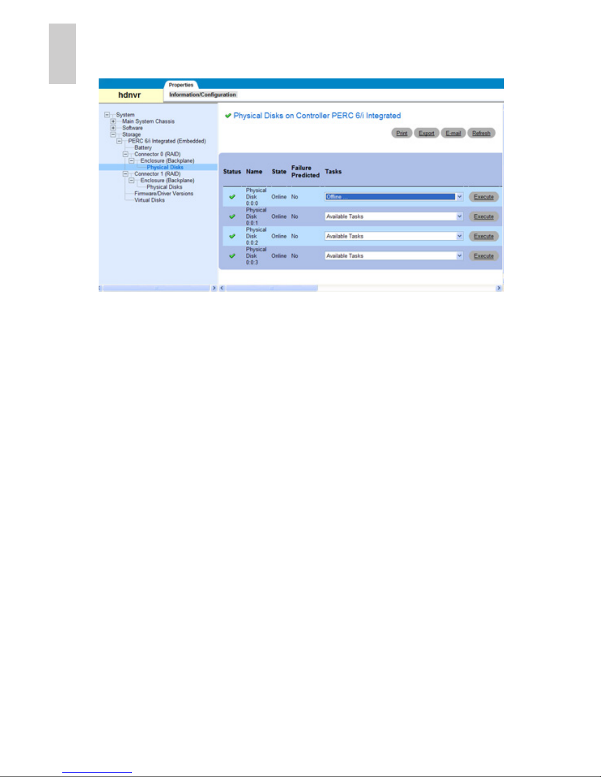
1. Open the Server Administrator.
2. In the System Tree on the left pane, select System >
Storage > Perc 6/i Integrated (Embedded) > Connector
0 (RAID) or Connector 1 (RAID) > Enclosure
(Backplane) > Physical Disks.
12
English
Connector 0 and Connector 1 give you access to different
hard drives.
3. In the workspace, locate the hard drive you want to replace.
To help you locate the hard drive, select Blink in the
Available Tasks drop down list then click Execute. The LED
indicators on the selected hard drive will start blinking.
Select Unblink and click Execute to have it stop.
4. For the hard drive you want to replace, select Offline from
the Available Tasks drop down list and click Execute. The
hard drive will be disconnected from the server for removal.
a. When the Confirmation page appears, click Offline.
b. When the Confirmation dialog box appears, click OK.
The hard drive is listed as Offline in the Server
Administrator, and the physical hard drive starts blinking.
5. Press the release button on the front left of the hard drive.
When the handle is released, pull the hard drive out of the
server.
13
English
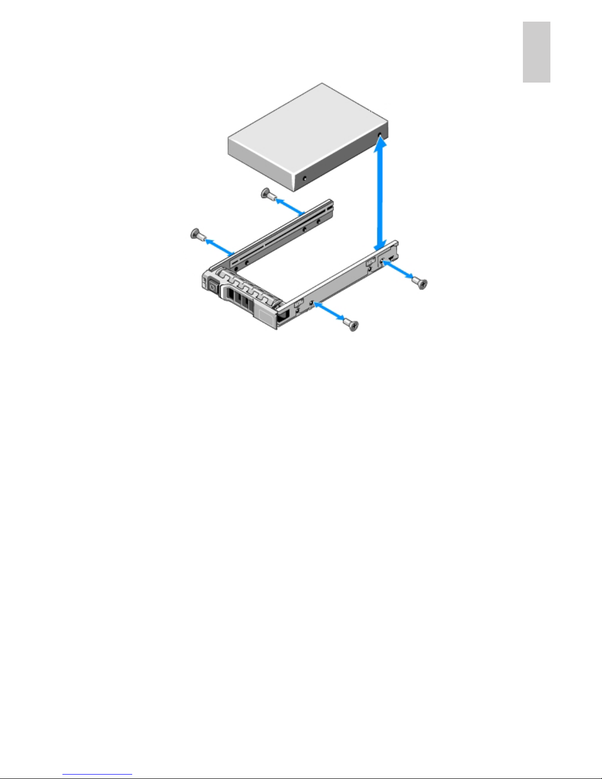
6. Remove the screws from the side of the hard drive carrier to
remove the hard drive.
7. Install a new hard drive into the hard drive carrier then reattach the screws. The hard drive connectors should face
the back.
8. When the hard drive is secured in the carrier, insert the
hard drive back into the server.
9. Once the hard drive is inserted all the way in, push the
handle against the hard drive to lock it into place.
The server immediately starts rebuilding the hard drive. The
progress is displayed in the Server Administrator.
When the hard drive comes online, normal operations can be
resumed.
14
English
LED Indicators
The following tables describe what the LEDs on the server indicate.
Power Status Indicators
The power button on the front of the server lights up when power is
on.
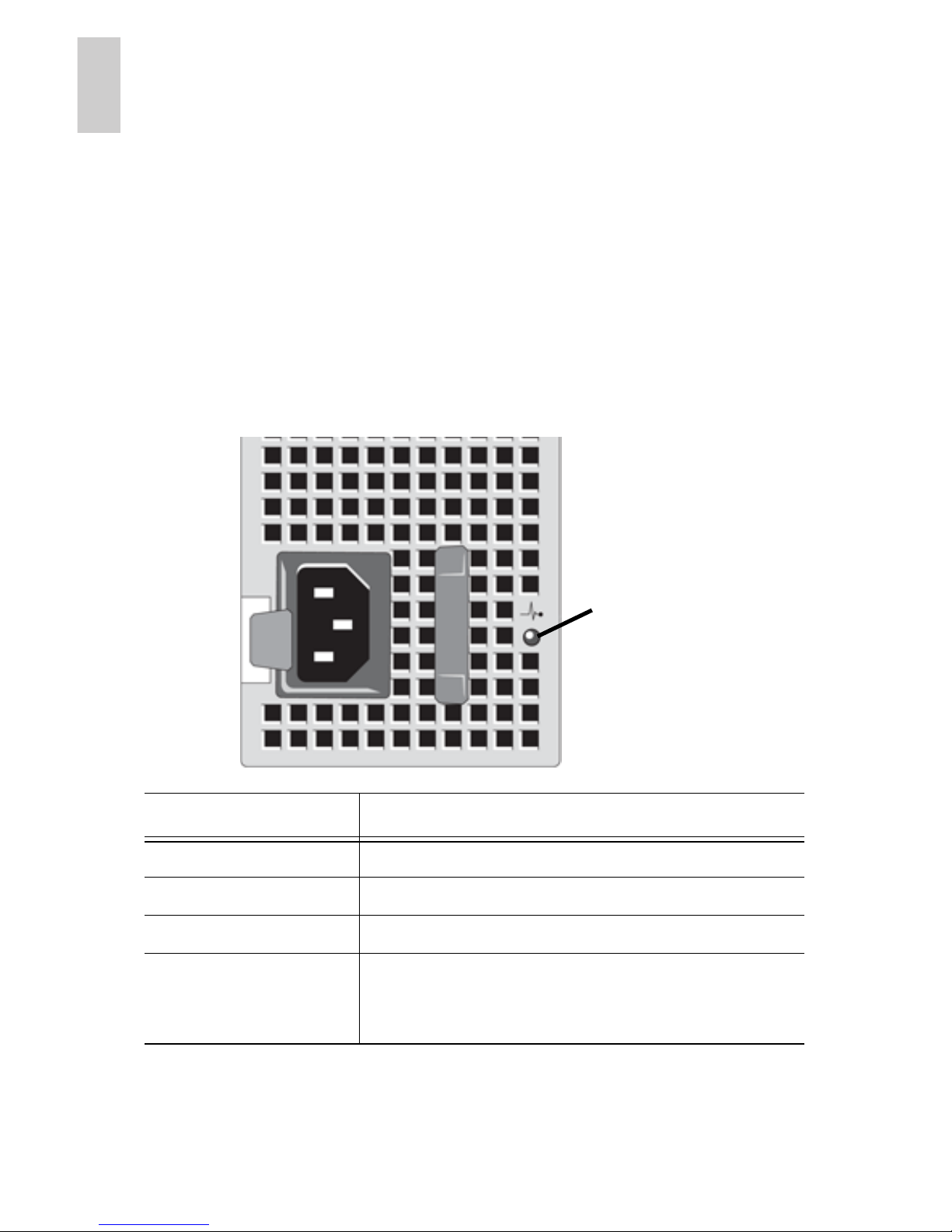
Additional information about the power supply is provided by the
power status indicator on the back of the server. The following table
describes what the LEDs indicate:
LED Indicator Description
Off Power is not connected.
Green Power is supplied to the server.
Orange There is a problem with the power supply
Alternates between
green and orange
The redundant power supply is mismatched.
This only occurs if you have a secondary
redundant power supply installed.
Status LED
15
English
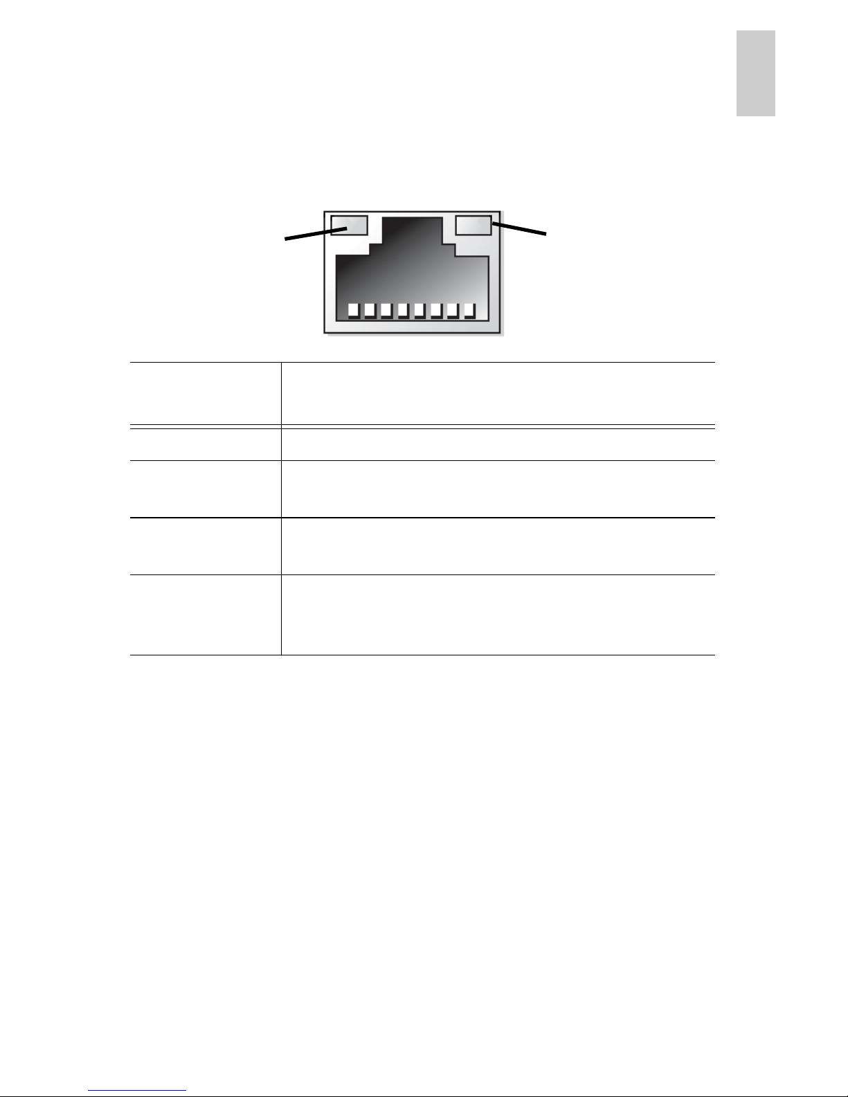
Network Link Status Indicator
When the server is connected to the network, the server’s
connection status LEDs above the Ethernet port display the
server’s connection status to the network. The following table
describes what the LEDs indicate:
LED
Indicators
Description
Off The server is not connected to the network.
Link LED is
green
The server is connected to the network at
1000 Mbps.
Link LED is
orange
The server is connected to the network at 10/
100 Mbps.
Connection
Status LED is
green
The server is working with other parts of the
Avigilon Control Center.
Link LED
Connection
Status LED
16
English
Hard Drive RAID Status Indicators
Each hard drive has its own set of LED indicators to show its
activity and status.
The Activity LED flashes green when the hard drives are working.
The following table describes what the Status LEDs indicate:
LED
Indicators
Description
Green The hard drive is online.
Off The hard drive is disconnected from the server.
Two short
green flashes
every second
Identifying a new hard drive, or preparing a hard
drive for removal.
Flashes green,
orange then
off
Hard drive is predicted to fail.
Four short
orange flashes
per second
Hard drive has failed.
Flashes green
slowly
Hard drive is rebuilding.
Activity LED
Status LED

17
English
Specifications
System
Avigilon Control Center
Server software
Enterprise and Standard edition compatible
Operating System Microsoft Windows XP
Hard Disk Drive Configuration 6 SATA, hot swappable, RAID 5
Mechanical
Dimensions (L x W x H) 681 mm x 443 mm x 86 mm (26.8” x 17.4” x 3.4”)
Weight 26 kg (57.4 lbs)
Form Factor 2U rack
Electrical
Power Input 100 to 240 VAC, 50/60 Hz, auto-switching
Power Consumption 570 W
Power Supply Single hot-swappable, dual redundant option
(HD-NVR-2ND-PS)
Environmental
Operating Temperature 10°C to 35°C (50°F to 95°F)
Storage Temperature -40° C to 65° C (-40° F to 149° F)
Humidity 20 - 80% Relative humidity (non-condensing)
Operating Vibration 0.26 Grms at 5 Hz to 350 Hz for 2 minutes
Storage Vibration 1.54 Grms Random Vibration at 10 Hz to 250 Hz
for 15 minutes
Operating Shock 1 shock pulse of 41 G for up to 2 ms
Storage Shock 6 shock pulses of 71 G for up to 2 ms
Operating Altitude -16 m to 3048 m (-50 ft to 10,000 ft)
Storage Altitude -16 m to 10,600 m (-50ft to 35,000ft)
Certifications
EN 60950-1:2006 + A11:2009
IEC 60950-1:2005 Ed2 EN 62311:2008
Electromagnetic Emissions EN 55022:2006 + A1:2007
CISPR 22:2005 + A1:2005
EN 61000-3-2:2006
IEC 61000-3-2:2005 (Class D)
EN 61000-3-3:1995 + A1:2001 + A2:2005
IEC 61000-3-3:1994 + A1:2001 + A2:2005
Electromagnetic Immunity EN 55024:1998 + A1:2001 + A2:2003
CISPR 24:1997 (modified)+A1:2001 + A2:2002

18
English
Limited Warranty & Technical Support
Avigilon warrants to the original consumer purchaser, that this
product will be free of defects in material and workmanship for a
period of 3 years from date of purchase. The manufacturer’s
liability hereunder is limited to replacement of the product, repair of
the product or replacement of the product with repaired product at
the discretion of the manufacturer. This warranty is void if the
product has been damaged by accident, unreasonable use,
neglect, tampering or other causes not arising from defects in
material or workmanship. This warranty extends to the original
consumer purchaser of the product only.
AVIGILON DISCLAIMS ALL OTHER WARRANTIES EXPRESSED
OR IMPLIED INCLUDING, WITHOUT LIMITATION, ANY IMPLIED
WARRANTIES OF MERCHANTABILITY OR FITNESS FOR A
PARTICULAR PURPOSE, EXCEPT TO THE EXTENT THAT ANY
WARRANTIES IMPLIED BY LAW CANNOT BE VALIDLY WAIVED.
No oral or written information, advice or representation provided by
Avigilon, its distributors, dealers, agents or employees shall create
another warranty or modify this warranty. This warranty states
Avigilon’s entire liability and your exclusive remedy against Avigilon
for any failure of this product to operate properly.
In no event shall Avigilon be liable for any indirect, incidental,
special, consequential, exemplary, or punitive damages
whatsoever (including but not limited to, damages for loss of profits
or confidential or other information, for business interruption, for
personal injury, for loss of privacy, for failure to meet any duty
including of good faith or of reasonable care, for negligence, and
for any other pecuniary or other loss whatsoever) arising from the
use of or inability to use the product, even if advised of the
possibility of such damages. Since some jurisdictions do not allow
the above limitation of liability, such limitation may not apply to you.
This Limited Warranty gives you specific legal rights and you may
also have other rights which vary from jurisdiction to jurisdiction.
Warranty service and technical support can be obtained by
contacting Avigilon Technical Support by phone at 1.888.281.5182
or via email at support@avigilon.com.

Guide d'installation
Serveur d'enregistreurs vidéo en réseau haute définition
Avigilon :
2.5TB-HD-NVR, 2.5TB-HD-NVR-LPR
5.0TB-HD-NVR, 5.0TB-HD-NVR-LPR
10.0TB-HD-NVR, 10.0TB-HD-NVR-LPR, 10.0TB-HD-NVR-EC2
15.0TB-HD-NVR, 15.0TB-HD-NVR-LPR, 15.0TB-HD-NVR-EC2
920-0047A-Rev1

Copyright © 9/27/11 Avigilon. Tous droits réservés.
Aucune reproduction, distribution, publication, modification, ou
incorporation de tout ou partie de ce document n'est autorisée sans
l'autorisation écrite expresse d'Avigilon. En cas d'autorisation de
reproduction, distribution, publication, modification ou incorporation de ce
document, aucune modification ou suppression du crédit de l'auteur, de la
légende des marques commerciales ou de l'avis de droits de reproduction
ne devra être effectuée. Aucune partie de ce document ne peut être
reproduite, stockée sur un système de récupération, publiée, exploitée à
des fins commerciales ou transmise, sous quelque forme que ce soit, par
quelque moyen que ce soit, notamment mais sans s'y limiter, le support
électronique ou mécanique, la photocopie ou l'enregistrement, sans
l'autorisation écrite expresse d'Avigilon.
Dell, PowerEdge R710, OpenManage Server Administrator et leurs
images sont des marques déposées de Dell.
Microsoft et Windows XP sont des marques déposées de Microsoft
Corporation.
Avigilon s'efforce autant que faire se peut d'identifier les propriétés faisant
l'objet d'une marque commerciale ainsi que leurs propriétaires sur cette
page. Toutes les marques et noms de produit utilisés dans ce document y
figurent à des fins informatives uniquement et peuvent constituer des
marques commerciales ou des marques déposées de leurs propriétaires
respectifs.
Avigilon
Téléphone : +1.604.629.5182
Télécopie : +1.604.629.5183
http://www.avigilon.com
Révisé 27/09/2011

Français
Tables des matières
Présentation générale . . . . . . . . . . . . . . 1
Avant . . . . . . . . . . . . . . . . . . . . . . . . . . . . . . . . 1
Retour . . . . . . . . . . . . . . . . . . . . . . . . . . . . . . . 2
Installation. . . . . . . . . . . . . . . . . . . . . . . . 3
Outils et matériel requis . . . . . . . . . . . . . . . . . . 3
Contenu du conditionnement . . . . . . . . . . . . . . 3
Étapes d'installation . . . . . . . . . . . . . . . . . . . . . 3
Installation des glissières de châssis
et du bras de gestion des câbles . . . . . 4
Raccordement des câbles . . . . . . . . . . 4
Installation du cache avant. . . . . . . . . . 4
Gestion des licences d'Avigilon
Control Center . . . . . . . . . . . . . . . . . . . 5
Affectation d'une adresse IP. . . . . . . . . 8
Caractéristiques avancées. . . . . . . . . . . 9
Administrateur serveur. . . . . . . . . . . . . . . . . . . 9
Connexion des unités
d'extension de stockage . . . . . . . . . . . . . . . 10
Remplacement des disques durs. . . . . . . . . . 11
Indications des LED . . . . . . . . . . . . . . . 14
Indicateurs d'état d'alimentation. . . . . . . . . . . 14
Indicateur d'état de liaison réseau . . . . . . . . . 15
Indicateurs d'état de la configuration
RAID des disques durs . . . . . . . . . . . . . . . . 16
Spécifications . . . . . . . . . . . . . . . . . . . . 17
Garantie limitée et
assistance technique . . . . . . . . . . . . . . 18

Français

1
Français
Présentation générale
Avant
Caractéristique Description
0 Cache avant Le cache avant protège le serveur des
accès physiques non autorisés. Le
cache avant doit être retiré pour
permettre l'accès à l'avant du serveur.
1 Verrou du cache avant Maintient le cache avant en place.
2 Bouton d'alimentation Contrôle l'alimentation du serveur.
3 Connecteur vidéo Accepte une connexion à un moniteur.
4 Connecteurs USB Accepte les connexions de type USB à
des périphériques extérieurs.
5 Écrans LCD des
messages
Affiche les messages d'erreur ainsi que
des informations relatives à l'état du
serveur.
6 Lecteur de DVD Donne accès au support DVD.
7 Disques durs Donne accès à six disques durs
échangeables à chaud. Chaque disque
dur dispose de LED d'indication.
Reportez-vous à la section Indications
des LED en page 14 pour plus
d'informations.
2
Français
Retour
Caractéristique Description
1
Alimentation Accepte une entrée d'alimentation
électrique.
Une alimentation secondaire redondante
(HD-NVR-2ND-PS) peut être installée dans
l'espace de droite.
2
Connecteur
série
Accepte les connexions de type série à des
périphériques extérieurs.
3
Connecteur
vidéo
Accepte une connexion à un moniteur VGA.
4
Connecteurs
d'extension
Quatre connecteurs d'extension permettent
le raccordement d'unités d'extension de
stockage externes.
Une carte d'extension Avigilon NVR est préinstallée sur les modèles de serveur x.xTBNVR-EC2 (voir l'image).
5
Port Ethernet Accepte une connexion Ethernet à un
réseau.
6
Connecteurs
USB
Accepte les connexions de type USB à des
périphériques extérieurs.

3
Français
Installation
Outils et matériel requis
• Tournevis cruciforme n°1
Contenu du conditionnement
Assurez-vous que le conditionnement contient les éléments
suivants :
• Serveur Avigilon d'enregistreurs vidéo en réseau NVR
(Network Video Recorder) haute définition
• DVD d'installation du logiciel Avigilon Control Center
• DVD de récupération du logiciel Avigilon Control Center
• Câble d'alimentation
• Clavier USB
• Souris USB
• Cache avant et clé
• Kit de montage des glissières de châssis
• Kit de montage du bras de gestion des câbles, ou CMA
(Cable Management Arm)
Étapes d'installation
Avant de procéder à l'installation, consultez le Guide d'information
produit fourni avec le serveur pour obtenir des informations de
sécurité pertinentes.
• Installation des glissières de châssis et du bras de gestion
des câbles en page 4
• Raccordement des câbles en page 4
• Installation du cache avant en page 4
• Gestion des licences d'Avigilon Control Center en page 5
• Affectation d'une adresse IP en page 8

4
Français
Installation des glissières de châssis et du
bras de gestion des câbles
Si le serveur est installé sur un châssis, installez les glissières
adaptées et le bras de gestion des câbles fournis dans le
conditionnement du serveur. Suivez les procédures détaillées dans
les Instructions d'installation du châssis et les Instructions
d'installation du CMA fournies dans les kits de montage.
Les glissières de montages incluses sont conçues pour les châssis
à trous carrés. Si vous avez besoin de glissières pour châssis à
trous ronds (HD-NVR-RAILS-RND), contactez votre représentant
commercial Avigilon local.
Raccordement des câbles
Reportez-vous aux schémas du serveur de la section Présentation
générale pour localiser les différents connecteurs.
1. Connectez le clavier et la souris à un connecteur USB
disponible à l'avant ou à l'arrière du serveur.
2. Connectez un moniteur au connecteur vidéo placé à l'avant
du serveur.
3. Connectez le serveur à votre réseau au moyen d'un câble
réseau Ethernet.
4. Raccordez le câble d'alimentation à l'alimentation placée à
l'arrière du serveur.
5. Si vous installez une unité d'extension de stockage Avigilon
HD NVR avec votre serveur, raccordez le serveur à cette
extension. Reportez-vous à la section Connexion des
unités d'extension de stockage en page 10 pour plus
d'informations.
6. Appuyez sur le bouton d'alimentation placé en face avant
du serveur. Vérifiez que les LED d'indication du serveur
affichent bien l'état approprié. Reportez-vous à la section
Indications des LED en page 14 pour plus d'informations.
Installation du cache avant
Le cache avant s'installe à l'avant du serveur pour contribuer à
protéger le bouton d'alimentation et les disques durs de tout accès
non autorisé.
 Loading...