

Avigilon 1.3C-H4SL-D-IR, 2.0C-H4SL-DO-IR, 2.0C-H4SL-D, 2.0C-H4SL-D-IR, 3.0C-H4SL-DIR Installation Manual
...Page 1
InstallationGuide
Avigilon H4 SL DomeCamera Models with Surface Mount
Adapter:
1.3C-H4SL-D, 1.3C-H4SL-D-IR,1.3C-H4SL-DO-IR, 2.0C-H4SL-D,
2.0C-H4SL-D-IR, 2.0C-H4SL-DO-IR, 3.0C-H4SL-D, 3.0C-H4SL-DIR, 3.0C-H4SL-DO-IR
Page 2
Important Safety Information
This manual provides installation and operation information and precautions for the use of this camera. Incorrect
installation could cause an unexpected fault. Before installing this equipment read this manual carefully. Please
provide this manual to the owner of the equipment for future use.
The Warning symbol indicates the presence of dangerous voltage within and outside the product
enclosure that may constitute a risk of electric shock, serious injury or death to persons if proper
precautions are not followed.
The Caution symbol alerts the user to the presence of hazards that may cause minor or moderate injury
to persons, damage to property or damage to the product itself if proper precautions are not followed.
WARNING — Failure to observe the following instructions may result in severe injury or death.
l Installation must be performed by qualified personnel only, and must conform to all local codes.
l The H4SL-D product is intended to be supplied by Power over Ethernet (PoE) that is a “Limited Power
Source” or “LPS” rated 48 VDC, 4W min.
l The H4SL-DO product is intended to be supplied by Power over Ethernet (PoE) that is a “Limited Power
Source” or “LPS” rated 48 VDC, 7W min.
l Any external power supply connected to this product may only be connected to another Avigilon
product of the same model series. External power connections must be properly insulated.
l Do not connect directly to mains power for any reason.
CAUTION — Failure to observe the following instructions may result in injury or damage to the camera.
l Do not expose the camera directly to high levels of x-ray, laser, or UV radiation. Direct exposure may
cause permanent damage to the image sensor.
l Do not install near any heat sources such as radiators, heat registers, stoves, or other sources of heat.
l Do not subject the cables to excessive stress, heavy loads or pinching.
l Do not open or disassemble the device. There are no user serviceable parts.
l Refer all servicing to qualified personnel. Servicing may be required when the device has been damaged
(such as from a liquid spill or fallen objects), has been exposed to rain or moisture, does not operate
normally, or has been dropped.
l Do not use strong or abrasive detergents when cleaning the device body.
l Use only accessories recommended by Avigilon.
ii
Page 3
Regulatory Notices
This device complies with part 15 of the FCC Rules. Operation is subject to the following two conditions: (1)this
device may not cause harmful interference, and (2) this device must accept any interference received, including
interference that may cause undesired operation.
This Class B digital apparatus complies with Canadian ICES-003.
FCC Notice
This equipment has been tested and found to comply with the limits for a Class B digital device, pursuant to Part
15 of the FCC rules. These limits are designed to provide reasonable protection against harmful interference in a
residential installation. This equipment generates, uses and can radiate radio frequency energy and, if not
installed and used in accordance with the instructions, may cause harmful interference to radio communications.
However, there is no guarantee that interference will not occur in a particular installation. If this equipment does
cause harmful interference to radio or television reception, which can be determined by turning the equipment
off and on, the user is encouraged to try to correct the interference by one or more of the following measures:
l Reorient or relocate the receiving antenna.
l Increase the separation between the equipment and the receiver.
l Connect the equipment into an outlet on a circuit different from that to which the receiver is connected.
l Consult the dealer or an experienced radio/TV technician for help.
Changes or modifications made to this equipment not expressly approved by Avigilon Corporation or parties
authorized by Avigilon Corporation could void the user’s authority to operate this equipment.
Disposal and Recycling Information
When this product has reached the end of its useful life, please dispose of it according to your local
environmental laws and guidelines.
Risk of fire, explosion, and burns. Do not disassemble, crush, heat above 100 °C (212 °F), or incinerate.
European Union:
This symbol means that according to local laws and regulations your product should be disposed of separately
from household waste. When this product reaches its end of life, take it to a collection point designated by local
authorities. Some collection points accept products for free. The separate collection and recycling of your
product at the time of disposal will help conserve natural resources and ensure that it is recycled in a manner
that protects human health and the environment.
iii
Page 4

Legal Notices
©2016 -2017,Avigilon Corporation. All rights reserved. AVIGILON, the AVIGILON logo, AVIGILONCONTROL
CENTER, ACC, and TRUSTED SECURITY SOLUTIONS are trademarks of Avigilon Corporation. Other names
mentioned herein may be the trademarks of their respective owners. The absence of the symbols ™ and ® in
proximity to each trademark in this document is not a disclaimer of ownership of the related trademark. Avigilon
Corporation protects its innovations with patents issued in the United States of America and other jurisdictions
worldwide: avigilon.com/patents. Unless stated explicitly and in writing, no license is granted with respect to
any copyright, industrial design, trademark, patent or other intellectual property rights of Avigilon Corporation or
its licensors.
Disclaimer
This document has been compiled and published covering the latest product descriptions and specifications.
The contents of this document and the specifications of the products discussed herein are subject to change
without notice. Avigilon Corporation reserves the right to make any such changes without notice. Neither
Avigilon Corporation nor any of its affiliated companies: (1) guarantees the completeness or accuracy of the
information contained in this document; or (2) is responsible for your use of, or reliance on, the information.
Avigilon Corporation shall not be responsible for any losses or damages (including consequential damages)
caused by reliance on the information presented herein.
Avigilon Corporation
avigilon.com
PDF-H4SLDO-A
Revision: 2 - EN
20170307
iv
Page 5

Table of Contents
Overview 1
Cover View 1
Mounting Adapter View 2
Camera Base Bottom View 3
Camera Base Front View 4
Camera Base Rear View 5
Installation 6
Required Tools and Materials 6
Camera Package Contents 6
Installation Steps 6
Removing the Dome Cover 7
Inserting Cables through the Sealing Grommet 7
Using the Surface Mount Adapter 8
Mounting the Dome Camera Using theBottom Cable Entry 8
Mounting the Dome Camera Using the Side Cable Entry 9
Mounting the Dome Camera to an Electrical Box 12
Installing the Camera Base to the Mounting Adapter 12
(Optional) Using the USB Wi-Fi Adapter 13
Assigning an IP Address 14
Accessing the Live VideoStream 14
Aiming the Dome Camera 14
(Optional) Configuring microSD Card Storage 16
Installing the Dome Cover 17
Zooming and Focusing the DomeCamera 17
Configuring the Camera 17
For More Information 18
LED Indicators 19
Removing the Dome Camera from the Mounting Adapter 20
Resetting to Factory Default Settings 21
Setting the IP Address Using the ARP/Ping Method 22
Specifications 23
Limited Warranty and Technical Support 25
v
Page 6
Overview
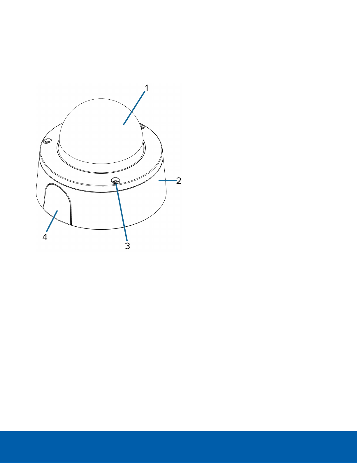
Cover View
1.
Dome cover
Vandal resistant dome cover.
Only available on H4SL-DO models.
2.
Surface mount adapter
Used to mount the dome camera to a wall, ceiling or electrical box.
3.
Tamper resistant screws
Torx captive screws to fix the dome cover to the base.
4. Side cable entry cover
Covers the side cable entry hole.
Overview 1
Page 7
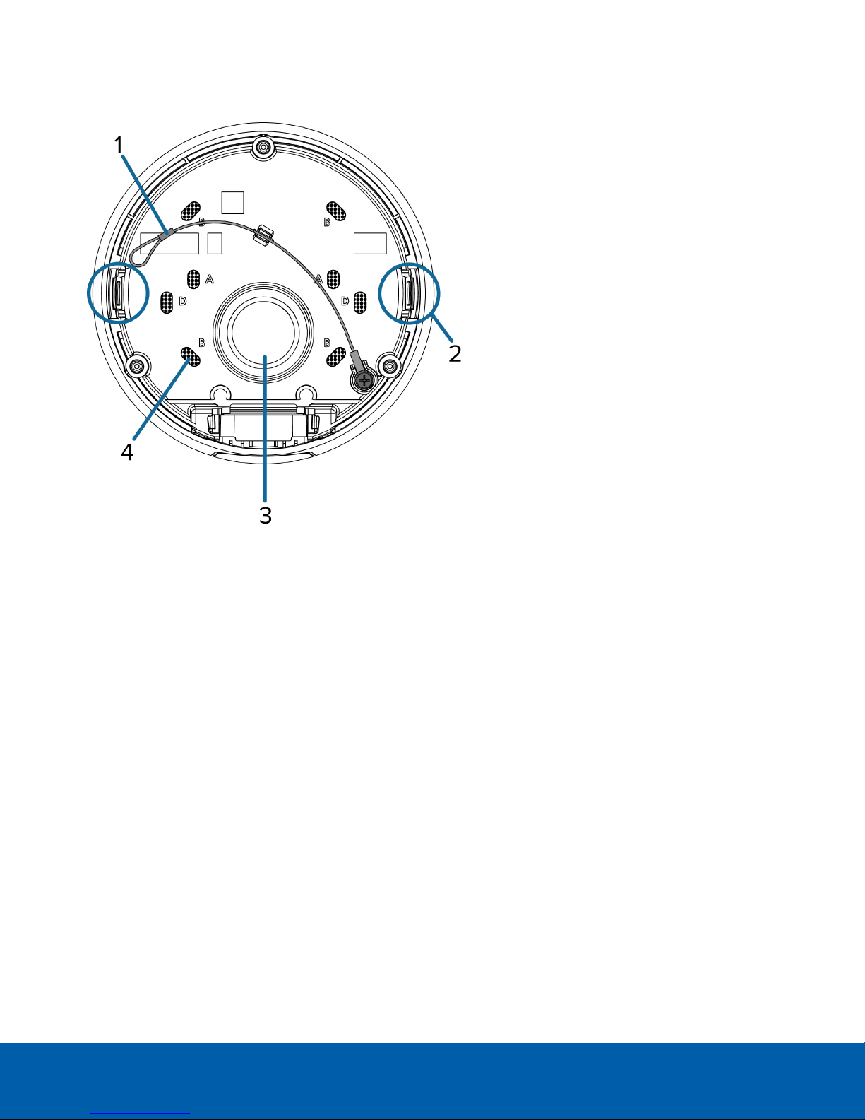
Mounting Adapter View
1.
Lanyard
Connects to the lanyard anchor on the dome camera base.
2.
Camera housing clips
Snaps to hold camera module during installation.
3.
Cable entry hole
An entry hole for the cables required for camera operation.
4.
Mounting holes
Holes for mounting the adapter to the following:
A — UK standard single gang box
B — Octagon gang box
D — US standard single gang box
Mounting Adapter View 2
Page 8

Camera Base Bottom View
1.
Cable entry hole
An entry hole for the cables required for camera operation.
2.
Lanyard anchor
The safety lanyard attaches to the anchor to prevent the camera from falling during installation.
3.
Vent
Vent to allow moisture vapor to escape the sealed housing and equalize pressure.
Only available on H4SL-DO models.
Camera Base Bottom View 3
Page 9

Camera Base Front View
1.
IR illuminator
Provides scene illumination in the IR spectrum.
Only available on -IR models.
2.
Ethernet port
Accepts power and Ethernet connection to the network.
The camera can only be powered by Power over Ethernet (PoE). Server communication and image data
transmission also occur over this connection.
3.
Connection status LED
Provides information about camera operation. For more information, see LED Indicators on page19.
4.
Link LED
Indicates if there is an active connection in the Ethernet port.
5.
microSD card slot
Accepts a microSD card for onboard storage.
Camera Base Front View 4
Page 10

Camera Base Rear View
Displayed IR illuminators only available on -IR models.
1.
Azimuth control
Provides control of the image angle.
2.
Tilt lock thumb screw
Provides a locking mechanism for the image tilt adjustment.
3.
Pan lock latch
Provides a locking mechanism for the image pan adjustment
4.
Micro USB port
Accepts a micro USB to USB adapter. Only required when using the Avigilon USB Wi-Fi Adapter.
5.
Serial number tag
Device information, product serial number and part number label.
Camera Base Rear View 5
Page 11

Installation
Required Tools and Materials
The following tools are required to complete the camera installation but are not included in the camera
package:
l No. 2 Phillips screwdriver — for attaching camera to an electrical box or mounting surface.
l T20 Pin-In Torx® driver
Camera Package Contents
Ensure the package contains the following:
l Avigilon H4 SL Dome Camera (Indoor model — H4SL-D)
o
Mounting template sticker
o
4 screws and anchors for solid walls
o
Surface mount adapter
o
Side conduit cover
l Avigilon H4 SL Dome Camera (Outdoor model — H4SL-DO)
o
Mounting template sticker
o
RJ-45 grommet piercing cap
o
4 screws and anchors for solid walls
o
Surface mount adapter
o
Side conduit cover
o
Side conduit plate (2 sizes)
o
Conduit grommet
o
Cable entry grommet
Installation Steps
Complete the following steps to install the camera:
Removing the Dome Cover 7
Inserting Cables through the Sealing Grommet 7
Using the Surface Mount Adapter 8
Installing the Camera Base to the Mounting Adapter 12
(Optional) Using the USB Wi-Fi Adapter 13
Assigning an IP Address 14
Installation 6
Page 12

Accessing the Live VideoStream 14
Aiming the Dome Camera 14
(Optional) Configuring microSD Card Storage 16
Installing the Dome Cover 17
Zooming and Focusing the DomeCamera 17
Configuring the Camera 17
Removing the Dome Cover
NOTE: Be careful not to scratch or touch the dome bubble. The resulting marks or fingerprints may affect the
overall image quality. Keep the protective covers on the outside of the dome bubble until the installation is
complete.
l Remove the dome cover by releasing the elastic strap holding the dome cover to the camera base.
Inserting Cables through the Sealing Grommet
Always use the provided sealing grommet to prevent dust and debris from entering the camera.
1. Remove the sealing grommet from the camera base.
2. Push the Ethernet cable through the grommet.
If you are installing the indoor model (H4SL-D), you should be able to simply push the cable, crimped or
uncrimped, through the grommet by hand.
If you are installing the outdoor model (H4SL-DO), use one of the following methods:
Removingthe Dome Cover 7
Page 13

a. If the Ethernet cable is uncrimped, push the cable through the grommet.
b. If the Ethernet cable is already crimped, place the grommet piercing cap on the Ethernet
connector then push the cable through the grommet.
Ensure that the orientation of the cable and grommet matches the one shown in the image.
Using the Surface Mount Adapter
The dome camera is provided with a surface mount adapter that can be mounted to a wall, ceiling or electrical
box.
If the dome camera needs to be installed in a different way, use one of the other mounting adapter options and
refer to their installation manuals for more information.
l In-ceiling mounting adapter (H4SL-MT-DCIL)
l Pendant NPT mounting adapter (H4SL-MT-NPTA)
o
Pendant wall mounting adapter (CM-MT-WALL) — must be used with NPT mounting adapter.
Mounting the Dome Camera Using theBottom Cable Entry
Perform the following steps if the required cables will be coming from inside the mounting surface and the
camera will be mounted immediately over the cable hole. Use this procedure on surfaces that can be easily
drilled into, and when the cables should be kept out of sight.
Perform the following steps to mount the dome camera to a ceiling or wall:
1. Use the mounting template to drill 4 mounting holes into the mounting surface and drill the cable entry
hole.
2. Pull the required Ethernet cable through the cable entry hole.
Make sure the Ethernet cable is threaded through the sealing grommet from the camera base. For more
information, see Inserting Cables through the Sealing Grommet on the previous page
3. Drive 4 screws to fasten the mounting adapter to the ceiling or wall.
Usingthe Surface Mount Adapter 8
Page 14

Mounting the Dome Camera Using the Side Cable Entry
Perform the following steps if you will be mounting to a surface with the required cables coming out of an
external conduit pipe. Use this procedure if the mounting surface cannot be easily cut, or when cables must be
brought along the outside of the mounting surface.
1. Use the mounting template to drill four mounting holes into the mounting surface.
Make sure the mounting template is aligned to where the conduit will enter the mounting adapter.
2. Pull the required Ethernet cable through the conduit.
3. Slide the side cable cover off the mounting adapter.
Mounting the Dome Camera Usingthe Side Cable Entry 9
Page 15

4. Depending on the conduit used, make the required adjustments to the side cable entry hole:
l If you are using a 1/2" or 20mm interior conduit, install the provided side conduit cover on to the
mounting adapter.
l If using ¾” or 25mm interior conduit, remove the center knockout piece on the provided side
conduit cover then install the side conduit cover on to the mounting adapter.
Mounting the Dome Camera Usingthe Side Cable Entry 10
Page 16

l If using ½” or ¾” exterior conduit, install a conduit plate to an external conduit adaptor then slide
the mounting adaptor over the conduit and plate assembly. Ensure the plate is compatible with the
type of conduit used.
If you are installing the outdoor model (H4SL-DO), you may need to cut off part of the rubber
gasket on the mounting adapter to make room for the plate.
Mounting the Dome Camera Usingthe Side Cable Entry 11
Page 17

5. Drive 4 screws to fasten the mounting adapter to the ceiling or wall.
Mounting the Dome Camera to an Electrical Box
Perform the following steps if the required electrical components and cables will be contained in an electrical
gang box inside the mounting surface.
1. Pull the required Ethernet cable through the cable entry hole.
Make sure the Ethernet cable is threaded through the sealing grommet from the camera base. For more
information, see Inserting Cables through the Sealing Grommet on page7.
2. Use pan head screws to install the mounting adapter to the electrical box.
Select the hole configuration that matches the electrical box shape:
A — UK standard single gang box
B — Octagon gang box
D — US standard single gang box
Installing the Camera Base to the Mounting Adapter
After you install the mounting adapter, mount the camera base to the adapter.
Mounting the Dome Camera to an Electrical Box 12
Page 18

1. Attach the lanyard on the mounting adapter to the anchor on the camera base.
2. Pull the required Ethernet cable through the cable entry hole on the camera base.
3. Install the grommet into the cable entry hole on the camera base.
Make sure the grommet flange is securely seated on the inside and outside of the cable entry hole.
4. Connect the cable to the Ethernet port.
The Link LED will turn on once a network link has been established.
5. Align the large orange arrow on the camera base to the side cable entry hole on the mounting adapter
then press the camera base into the mounting adapter. The camera base clicks into place and is held
securely.
(Optional) Using the USB Wi-Fi Adapter
If you have a USB Wi-Fi Adapter (H4-AC-WIFI), attach it to the camera's micro USB port to access the camera's
mobile web interface.
After you connect to the Wi-Fi signal broadcast by the adapter, you can access the mobile web interface from
any mobile device using the following address:
http://camera.lan
(Optional) Using the USB Wi-FiAdapter 13
Page 19

For more information about configuring the camera from the mobile web interface see Avigilon USB Wi-Fi
Adapter System User Guide.
NOTE: The camera will reserve the 10.11.22.32/28 subnet for internaluse while the USBWi-Fi Adapter isplugged in.
Assigning an IP Address
The camera automatically obtains an IP address when it is connected to a network.
NOTE: If the camera cannot obtain an IP address from a DHCP server, it will use Zero Configuration Networking
(Zeroconf) to choose an IP address. When set using Zeroconf, the IP address is in the 169.254.0.0/16 subnet.
The IP address settings can be changed using one of the following methods:
l The mobile web interface using the USB Wifi Adapter. For more information, see (Optional) Using the USB
Wi-Fi Adapter on the previous page.
l Camera's web browser interface: http://<camera IP address>/.
l Network Video Management software application (for example, the Avigilon Control Center™ software).
l ARP/Ping method. For more information, see Setting the IP Address Using the ARP/Ping Method on
page22.
NOTE: The default camera username is administrator with no password.
Accessing the Live VideoStream
Live video stream can be viewed using one of the following methods:
l The mobile web interface using the USB Wifi Adapter. For more information, see (Optional) Using the USB
Wi-Fi Adapter on the previous page.
l Web browser interface: http://< camera IP address>/.
l Network Video Management software application (for example, the Avigilon Control Center software).
NOTE: The default camera username is administrator with no password.
Aiming the Dome Camera
Reference the camera's live stream as you aim the camera.
Assigningan IP Address 14
Page 20

1. Unlock the pan lock latch on the camera base, then pan the lens until it is aimed in the correct direction.
If the camera stops panning before it reaches its final destination, stop and pan the camera in the
opposite direction.
2. Loosen the tilt lock thumb screw to tilt the lens.
3. Lock the pan lock latch and tighten the tilt lock screw to secure the dome camera’s position.
Aiming the Dome Camera 15
Page 21

4. Rotate the azimuth control ring to set the image to the correct angle.
5. In the camera web browser interface or the Avigilon Control Center software, adjust the camera’s Image
and Display settings.
(Optional) Configuring microSD Card Storage
To use the camera's SD card storage feature, you must insert an microSD card into the card slot.
It is recommended that the microSD card have a write speed of class 10 or better. If the microSD card does not
meet the recommended write speed, the recording performance may suffer and result in the loss of frames or
footage.
1. Insert a microSD card into the camera.
CAUTION — Do not force the microSD card into the camera or you may damage the card and the
camera.
2. Access the camera’s web interface to enable the onboard storage feature. For more information, see the
Avigilon High Definition H.264 Camera Web Interface User Guide.
(Optional) Configuring micr oSD Card Storage 16
Page 22

Installing the Dome Cover
1. Attach the dome cover to the base by tightening the screws with the Torx driver.
2. Remove the protective cover on the outside of the dome bubble.
Zooming and Focusing the DomeCamera
Ensure this procedure is performed after the dome cover is installed so you can accommodate for the focus
shift caused by the dome bubble.
NOTE: If the H4SL-DO camera model is powered while the temperature is below -30 °C (-22 °F), the zoom and
focus may be disabled for the first 45 minutes while the camera warms up.
l In the camera web browser interface or the Avigilon Control Center software, use the camera’s Image
and Display settings to zoom and focus the camera.
a. Use the zoom buttons to zoom the camera in or out.
b. Click Auto Focus to focus the lens.
c. Use the focus near and far buttons to manually adjust the focus.
Configuring the Camera
Once installed, use one of the following methods to configure the camera:
l If you have the USB Wifi Adapter, you can access the mobile web interface to configure the camera. For
more information, see Avigilon USB Wi-Fi Adapter System User Guide.
l If you have installed multiple cameras, you can use the Avigilon Camera Configuration Tool to configure
common settings. For more information, see the Avigilon Camera Configuration Tool User Guide.
l If the camera is connected to the Avigilon Control Center system, you can use the client software to
configure the camera. For more information, see the Avigilon Control Center Client User Guide.
l If the camera is connected to a third-party network management system, you can configure the camera's
specialty features in the camera's web browser interface. For more information, see the Avigilon H.264
Web Interface User Guide.
Installing the Dome Cover 17
Page 23

For More Information
Additional information about setting up and using the device is available in the following guides:
l Avigilon Control Center Client User Guide
l Avigilon High Definition H.264 Web Interface User Guide
l Avigilon Camera Configuration Tool User Guide
The manuals are available on the Avigilon website: avigilon.com/support-and-downloads.
For More Information 18
Page 24

LED Indicators
Once connected to the network, the Connection Status LED will display the progress in connecting to the
Network Video Management software.
The following table describes what the LEDs indicate:
Connection State
Obtaining IPAddress
Discoverable
Upgrading Firmware
Connected On
Connection Status
One short flash every
second
Two short flashes
every second
Two short flashes
and one long flash
every second
LED
Description
Attempting to obtain an IP address.
Obtained an IPaddress but is not connected to the
NetworkVideo Management software.
Updating the firmware.
Connected to the Network Video Management software or an
ACC™ Server.
LEDIndicators 19
Page 25

Removing the Dome Camera from the Mounting
Adapter
1. Loosen the Torx screws and remove the dome cover.
2. Locate the small orange arrows that point at the camera housing clips.
3. Insert a flat head screwdriver or grommet piercing cap against one of the camera housing clips.
4. Lever one side of the camera base out of the clip.
5. Lift the camera base out of the adapter.
Removingthe Dome Camera from the Mounting Adapter 20
Page 26

Resetting to Factory Default Settings
If the camera no longer functions as expected, you can choose to reset the camera to its factory default settings.
Use the firmware revert button to reset the camera. The firmware revert button is shown in the following
diagram:
1. Ensure the camera is powered on.
2. Using a straightened paperclip or similar tool, gently press and hold the firmware revert button.
3. Release the button after three seconds.
CAUTION — Do not apply excessive force. Inserting the tool too far will damage the camera.
Resetting to Factory Default Settings 21
Page 27

Setting the IP Address Using the ARP/Ping Method
Complete the following steps to configure the camera to use a specific IP address:
NOTE: The ARP/Ping Method will not work if the Disable setting static IP address through ARP/Ping method
check box is selected in the camera's web browser interface. For more information, see the Avigilon™ High
Definition H.264 Web Interface User Guide.
1. Locate and copy down the MAC Address (MAC) listed on the Serial Number Tag for reference.
2. Open a Command Prompt window and enter the following commands:
a. arp -s <New Camera IP Address> <Camera MAC Address>
For example: arp -s 192.168.1.10 00-18-85-12-45-78
b. ping -l 123 -t <New Camera IP Address>
For example: ping -l 123 -t 192.168.1.10
3. Reboot the camera.
4. Close the Command prompt window when you see the following message:
Reply from <New Camera IP Address>: ...
Setting the IP Address Using the ARP/Ping Method 22
Page 28

Specifications
Camera
Lens 3-9mm, motorized, varifocal
USB Port USB 2.0
SD Storage
Network
Network 100Base-TX
Cabling Type CAT5
Connector RJ-45
API ONVIF® compliance version 1.02, 2.00, Profile S (www.onvif.org)
Device Management
Protocols
Security
Streaming Protocols
Mechanical
Dimensions
L x W x H
Weight
microSD/microSDHC/microSDXC slot – minimum class 6; class 10/UHS-1 or better
recommended
SNMP v2c
SNMP v3
Password protection, HTTPS encryption, digest authentication, WS authentication, user
access log, 802.1x port based authentication
IPv4, HTTP, HTTPS, SOAP, DNS, NTP, RTSP, RTCP, RTP, TCP, UDP, IGMP, ICMP, DHCP,
Zeroconf, ARP, RTP/UDP, RTP/UDP multicast, RTP/RTSP/TCP, RTP/RTSP/HTTP/TCP,
RTP/RTSP/HTTPS/TCP, HTTP
147 mm x 147 mm x 119 mm; (5.8” x 5.8” x 4.7”)
H4SL-D — 0.76 kg (1.68 lbs)
H4SL-DO — 0.78 kg (1.72 lbs)
Dome Bubble Polycarbonate, clear
Body Polycarbonate
Surface mount
Housing
Finish Fog coat, cool grey
Adjustment Range 360° pan, 30° – 95° tilt, ±180° azimuth
Electrical
Power Consumption
Power Source PoE: IEEE802.3af Class 3 compliant
RTC Backup Battery 3V manganese lithium
Environmental
Operating
Specifications 23
H4SL-D — tamper resistant
H4SL-DO — vandal resistant
H4SL-D — 4W max
H4SL-DO — 7 W max
H4SL-D — 0 °C to 55 °C (32 °F to 131 °F)
Page 29

Temperature H4SL-DO — -30 °C to 60 °C (-22 °F to 140 °F)
Storage Temperature -10 °C to 70 °C (14 °F to 158 °F)
Humidity 0-95% non-condensing
Certifications
UL
cUL
CE
Certifications
ROHS
WEEE
RCM
EAC
KC
UL 60950-1
Safety
CSA 60950-1
IEC/EN 60950-1
IEC 62471
Environmental
(H4SL-DO only)
Electromagnetic
Emissions
Electromagnetic
Immunity
IK10 Impact Rating
Meets IEC 60529 IP66 Weather Rating
IEC/UL/CSA 60950-22
FCC Part 15 Subpart B Class B
EN 55022 Class B
EN 55032
IC ICES-003 Class B
EN 61000-6-3
EN 61000-3-2
EN 61000-3-3
KN 32
EN 55024
EN 61000-6-1
EN 50130-4
KN 35
Specifications 24
Page 30

Limited Warranty and Technical Support
Avigilon warranty terms for this product is provided at avigilon.com/warranty.
Warranty service and technical support can be obtained by contacting Avigilon Technical Support:
avigilon.com/contact-us/.
Limited Warranty and Technical Support 25
 Loading...