

Avigilon 1.3C-H4SL-D1 Installation Manual

Regulatory Notices
This device complies with part 15 of the FCC Rules. Operation is subject to the following two conditions: (1)this
device may not cause harmful interference, and (2) this device must accept any interference received, including
interference that may cause undesired operation.
This Class B digital apparatus complies with Canadian ICES-003.
FCC Notice
This equipment has been tested and found to comply with the limits for a Class B digital device, pursuant to Part
15 of the FCC rules. These limits are designed to provide reasonable protection against harmful interference in a
residential installation. This equipment generates, uses and can radiate radio frequency energy and, if not
installed and used in accordance with the instructions, may cause harmful interference to radio communications.
However, there is no guarantee that interference will not occur in a particular installation. If this equipment does
cause harmful interference to radio or television reception, which can be determined by turning the equipment
off and on, the user is encouraged to try to correct the interference by one or more of the following measures:
l Reorient or relocate the receiving antenna.
l Increase the separation between the equipment and the receiver.
l Connect the equipment into an outlet on a circuit different from that to which the receiver is connected.
l Consult the dealer or an experienced radio/TV technician for help.
Changes or modifications made to this equipment not expressly approved by Avigilon Corporation or parties
authorized by Avigilon Corporation could void the user’s authority to operate this equipment.
Disposal and Recycling Information
When this product has reached the end of its useful life, please dispose of it according to your local
environmental laws and guidelines.
Risk of fire, explosion, and burns. Do not disassemble, crush, heat above 100 °C (212 °F), or incinerate.
European Union:
This symbol means that according to local laws and regulations your product should be disposed of separately
from household waste. When this product reaches its end of life, take it to a collection point designated by local
authorities. Some collection points accept products for free. The separate collection and recycling of your
product at the time of disposal will help conserve natural resources and ensure that it is recycled in a manner
that protects human health and the environment.
iii

Legal Notices
©2016 - 2017,Avigilon Corporation. All rights reserved. AVIGILON, the AVIGILON logo, AVIGILONCONTROL
CENTER, ACC, and TRUSTED SECURITY SOLUTIONS are trademarks of Avigilon Corporation. Other names
mentioned herein may be the trademarks of their respective owners. The absence of the symbols ™ and ® in
proximity to each trademark in this document is not a disclaimer of ownership of the related trademark. Avigilon
Corporation protects its innovations with patents issued in the United States of America and other jurisdictions
worldwide: http://www.avigilon.com/patents. Unless stated explicitly and in writing, no license is granted with
respect to any copyright, industrial design, trademark, patent or other intellectual property rights of Avigilon
Corporation or its licensors.
Disclaimer
This document has been compiled and published covering the latest product descriptions and specifications.
The contents of this document and the specifications of the products discussed herein are subject to change
without notice. Avigilon Corporation reserves the right to make any such changes without notice. Neither
Avigilon Corporation nor any of its affiliated companies: (1) guarantees the completeness or accuracy of the
information contained in this document; or (2) is responsible for your use of, or reliance on, the information.
Avigilon Corporation shall not be responsible for any losses or damages (including consequential damages)
caused by reliance on the information presented herein.
Avigilon Corporation
http://www.avigilon.com
PDF-H4SL-MT-NPTAWALL-A
Revision: 2 - EN
20170123
iv

Table of Contents
Overview 1
Cover View 1
NPT Adapter View 2
Pendant Wall Mount Bracket View 3
Pendant Wall Mount View 4
Camera Base Bottom View 5
Camera Base Front View 6
Camera Base Rear View 7
Installation 8
Required Tools and Materials 8
Package Content 8
Installation Steps 9
Removing the Dome Cover 9
Inserting Cables through the Sealing Grommet 10
Mounting the Dome Camera to a Pipe 11
(Optional) Mounting the Dome Camera to the Pendant Wall Mount 12
Installing the Camera Base to the Mounting Adapter 15
(Optional) Using the USB Wi-Fi Adapter 16
Assigning an IP Address 16
Accessing the Live VideoStream 16
Aiming the Dome Camera 17
(Optional) Configuring microSD Card Storage 18
Installing the Dome Cover 19
Zooming and Focusing the DomeCamera 19
Configuring the Camera 19
For More Information 20
LED Indicators 21
Removing the Dome Camera from the Mounting Adapter 22
Resetting to Factory Default Settings 23
Setting the IP Address Using the ARP/Ping Method 24
Specifications 25
Limited Warranty and Technical Support 27
v
Overview
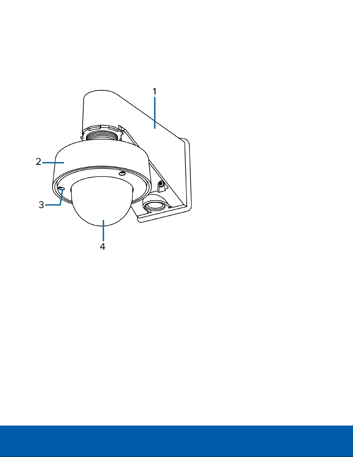
Cover View
1.
NPT adapter
Used to mount the dome camera to NPT pipes.
2. Pendant wall mount (optional)
Used with the NPT adapter to mount the dome camera to a wall in pendant installations.
3.
Tamper resistant screws
Torx captive screws to fix the dome cover to the base.
4.
Dome cover
Vandal resistant dome cover.
Only available on H4SL-DO models.
Overview 1
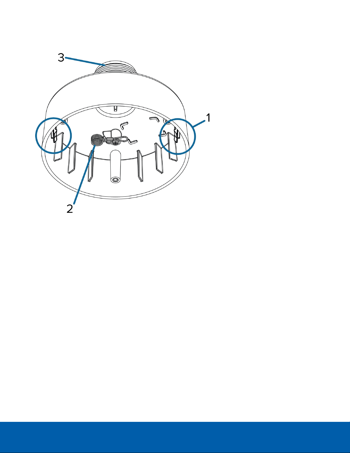
NPT Adapter View
1.
Camera housing clips
Snaps to hold camera module during installation.
2.
Lanyard
Connects to the lanyard anchor on the dome camera base.
3.
1-1/2” NPT thread mount
Standard male 1-1/2” NPT thread mount for mounting the dome camera to a pole or bracket.
NPT Adapter View 2

Pendant Wall Mount Bracket View
1.
Bracket mounting holes
Points for mounting the pendant wall mount bracket to a mounting surface.
2.
Mounting tabs
Tabs for placing the pendant wall mount onto the bracket.
3.
Mounting points
Points for securing the pendant wall mount to the mounting bracket.
Pendant Wall Mount Bracket View 3

Pendant Wall Mount View
1.
1-1/2” NPS thread mount
Female NPS thread mount for pendant camera installations.
2.
Pendant wall mount screws
Screws for securing the pendant wall mount to the mounting bracket.
3.
NPT pipe entry hole
A 3/4” NPT threaded hole for NPT pipe conduits.
Pendant Wall Mount View 4
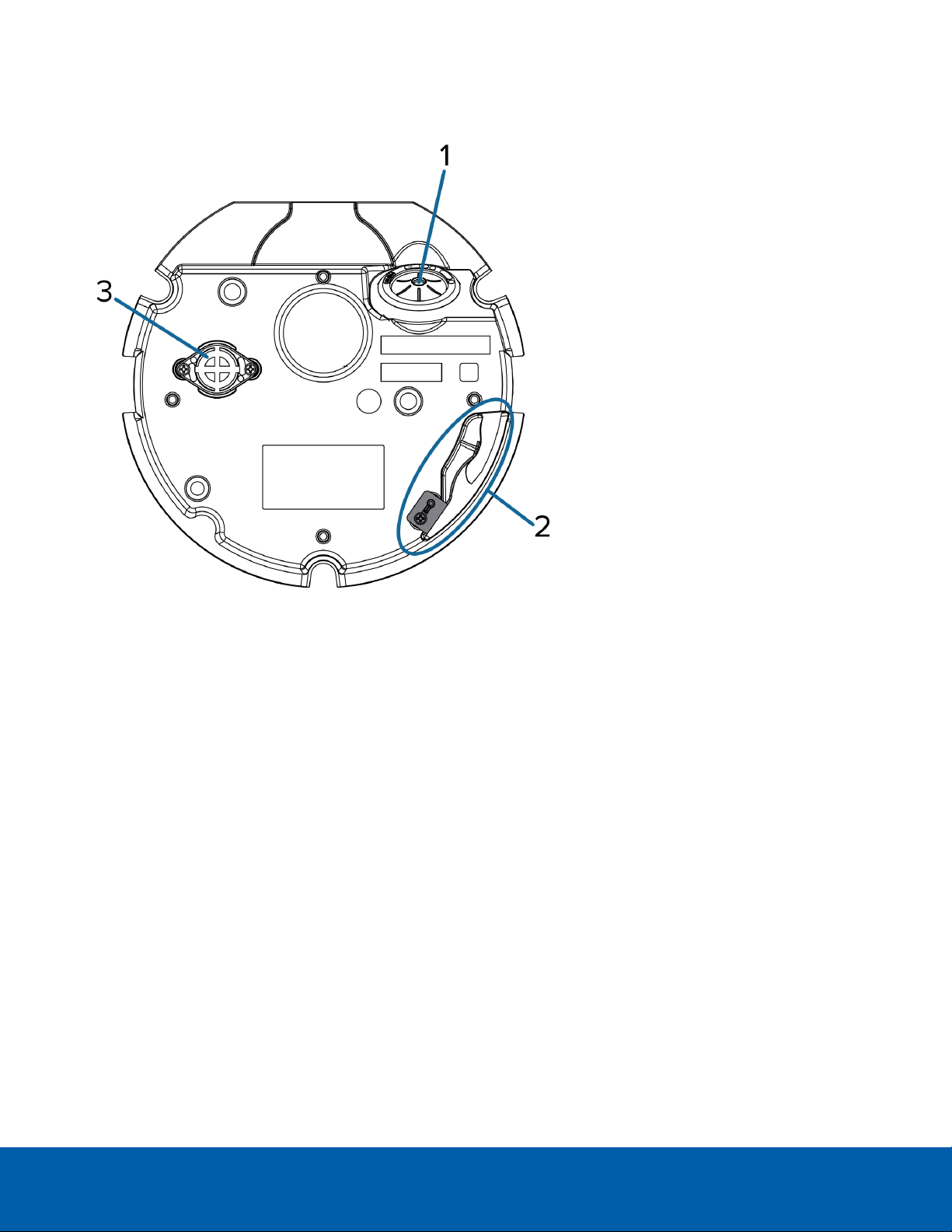
Camera Base Bottom View
1.
Cable entry hole
An entry hole for the cables required for camera operation.
2.
Lanyard anchor
The safety lanyard attaches to the anchor to prevent the camera from falling during installation.
3.
Vent
Vent to allow moisture vapor to escape the sealed housing and equalize pressure.
Only available on H4SL-DO models.
Camera Base Bottom View 5
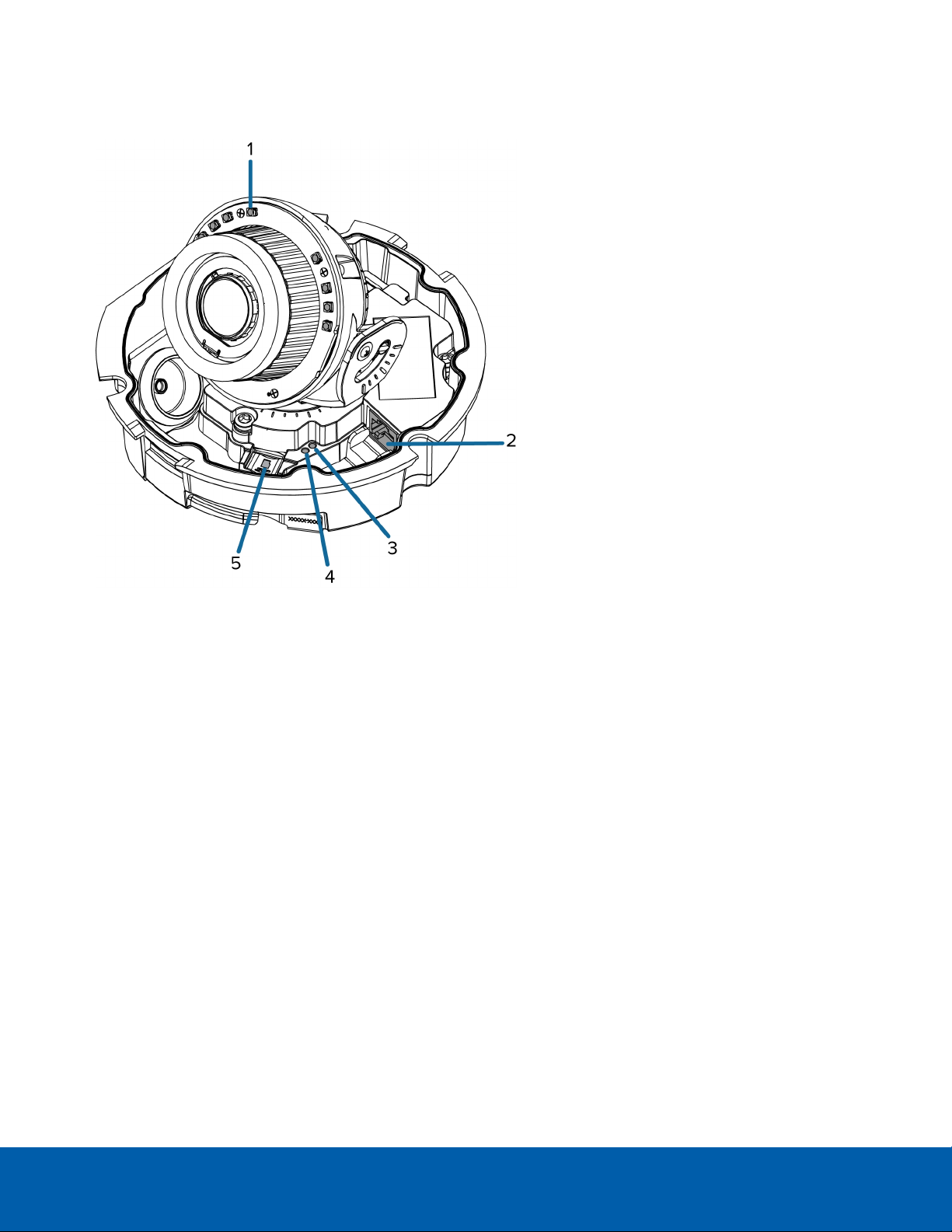
Camera Base Front View
1.
IR illuminator
Provides scene illumination in the IR spectrum.
Only available on -IR models.
2.
Ethernet port
Accepts power and Ethernet connection to the network.
The camera can only be powered by Power over Ethernet (PoE). Server communication and image data
transmission also occur over this connection.
3.
Connection status LED
Provides information about camera operation. For more information, see LED Indicators on page21.
4.
Link LED
Indicates if there is an active connection in the Ethernet port.
5.
microSD card slot
Accepts a microSD card for onboard storage.
Camera Base Front View 6
 Loading...