

Avigilon 6.0L-H4F-DO1-IR, 12.0-H4F-DO1-IR Installation Manual
Installation Guide
Avigilon™ H4 Fisheye Dome Camera Models:
6.0L-H4F-DO1-IR and 12.0-H4F-DO1-IR
Important Safety Information
This manual provides installation and operation information and precautions for the use of this camera. Incorrect
installation could cause an unexpected fault. Before installing this equipment read this manual carefully. Please
provide this manual to the owner of the equipment for future use.
The Warning symbol indicates the presence of dangerous voltage within and outside the product
enclosure that may constitute a risk of electric shock, serious injury or death to persons if proper
precautions are not followed.
The Caution symbol alerts the user to the presence of hazards that may cause minor or moderate injury
to persons, damage to property or damage to the product itself if proper precautions are not followed.
WARNING — Failure to observe the following instructions may result in severe injury or death.
l Installation must be performed by qualified personnel only, and must conform to all local codes.
l This product is intended to be used in an Network Environment 0 per IEC TR62101. The camera is to be
connected only to PoE network that complies with IEEE 802.3af without routing to the outside plant.
l This product is intended to be supplied by a UL Listed Power Unit marked “Class 2” or “LPS” or “Limited
Power Source” with output rated 12 VDC or Power over Ethernet (PoE), rated 48 VDC, 25.5W min.
l Any external power supply connected to this product may only be connected to another Avigilon
product of the same model series. External power connections must be properly insulated.
l Do not connect directly to mains power for any reason.
CAUTION — Failure to observe the following instructions may result in injury or damage to the camera.
l Do not expose the camera directly to high levels of x-ray, laser, or UV radiation. Direct exposure may
cause permanent damage to the image sensor.
l Do not install near any heat sources such as radiators, heat registers, stoves, or other sources of heat.
l Do not subject the cables to excessive stress, heavy loads or pinching.
l Do not open or disassemble the device. There are no user serviceable parts.
l Refer all servicing to qualified personnel. Servicing may be required when the device has been damaged
(such as from a liquid spill or fallen objects), has been exposed to rain or moisture, does not operate
normally, or has been dropped.
l Do not use strong or abrasive detergents when cleaning the device body.
l Use only accessories recommended by Avigilon.
ii
Regulatory Notices
This device complies with part 15 of the FCC Rules. Operation is subject to the following two conditions: (1)this
device may not cause harmful interference, and (2) this device must accept any interference received, including
interference that may cause undesired operation.
This Class B digital apparatus complies with Canadian ICES-003.
FCC Notice
This equipment has been tested and found to comply with the limits for a Class B digital device, pursuant to Part
15 of the FCC rules. These limits are designed to provide reasonable protection against harmful interference in a
residential installation. This equipment generates, uses and can radiate radio frequency energy and, if not
installed and used in accordance with the instructions, may cause harmful interference to radio communications.
However, there is no guarantee that interference will not occur in a particular installation. If this equipment does
cause harmful interference to radio or television reception, which can be determined by turning the equipment
off and on, the user is encouraged to try to correct the interference by one or more of the following measures:
l Reorient or relocate the receiving antenna.
l Increase the separation between the equipment and the receiver.
l Connect the equipment into an outlet on a circuit different from that to which the receiver is connected.
l Consult the dealer or an experienced radio/TV technician for help.
Changes or modifications made to this equipment not expressly approved by Avigilon Corporation or parties
authorized by Avigilon Corporation could void the user’s authority to operate this equipment.
Disposal and Recycling Information
When this product has reached the end of its useful life, please dispose of it according to your local
environmental laws and guidelines.
Risk of fire, explosion, and burns. Do not disassemble, crush, heat above 100 °C (212 °F), or incinerate.
European Union:
This symbol means that according to local laws and regulations your product should be disposed of separately
from household waste. When this product reaches its end of life, take it to a collection point designated by local
authorities. Some collection points accept products for free. The separate collection and recycling of your
product at the time of disposal will help conserve natural resources and ensure that it is recycled in a manner
that protects human health and the environment.
iii

Legal Notices
©2016,Avigilon Corporation. All rights reserved. AVIGILON, the AVIGILON logo, AVIGILONCONTROL
CENTER, ACC, and TRUSTED SECURITY SOLUTIONS are trademarks of Avigilon Corporation. Other product
names mentioned herein may be the trademarks of their respective owners. The absence of the symbols ™ and
® in proximity to each trademark in this document is not a disclaimer of ownership of the related trademark.
Avigilon Corporation protects its innovations with patents issued in the United States of America and other
jurisdictions worldwide: http://www.avigilon.com/patents. Unless stated explicitly and in writing, no license is
granted with respect to any copyright, industrial design, trademark, patent or other intellectual property rights of
Avigilon Corporation or its licensors.
Disclaimer
This document has been compiled and published covering the latest product descriptions and specifications.
The contents of this document and the specifications of the products discussed herein are subject to change
without notice. Avigilon Corporation reserves the right to make any such changes without notice. Neither
Avigilon Corporation nor any of its affiliated companies: (1) guarantees the completeness or accuracy of the
information contained in this document; or (2) is responsible for your use of, or reliance on, the information.
Avigilon Corporation shall not be responsible for any losses or damages (including consequential damages)
caused by reliance on the information presented herein.
Avigilon Corporation
http://www.avigilon.com
PDF-H4FDO-A
Revision: 2 - EN
20161031
iv

Table of Contents
Overview 1
Cover View 1
Internal View 2
Bottom View 3
Bracket View 4
NPT Adapter View 5
Installation 6
Required Tools and Materials 6
Camera Package Contents 6
Installation Steps 6
Removing the Dome Cover 7
Preparing the Cables 8
(Optional) Configuring microSD Card Storage 10
Mounting the Dome Camera 10
Mounting the Dome Camera to a Ceiling or Wall 10
Mounting the Dome Camera Using the Side Cable Entry Hole 13
Mounting the Dome Camera to an Electrical Box 17
Mounting the Dome Camera to an NPT Pipe 21
Connecting Cables 24
Assigning an IP Address 25
Accessing the Live VideoStream 26
Installing the Dome Cover 26
Configuring the Camera 27
For More Information 27
Auxiliary Cable Connections 29
Configuring the Microphone 29
LED Indicators 31
Resetting to Factory Default Settings 32
Setting the IP Address Using the ARP/Ping Method 33
Cleaning 34
Dome Bubble 34
Body 34
Specifications 35
Limited Warranty and Technical Support 37
v
Overview
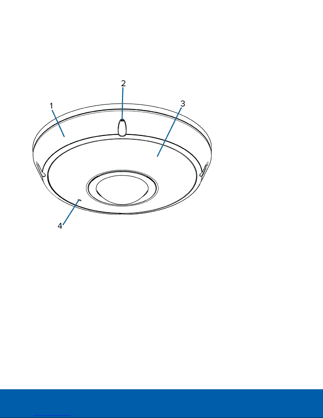
Cover View
1. Dome cover
Vandal resistant dome cover.
2. Tamper resistant scre ws
Torx captive screws to fix the dome cover to the base.
3. IR illuminator
Provides scene illumination in the IR spectrum.
4. Microphone
Built-in audio receiver.
Overview 1
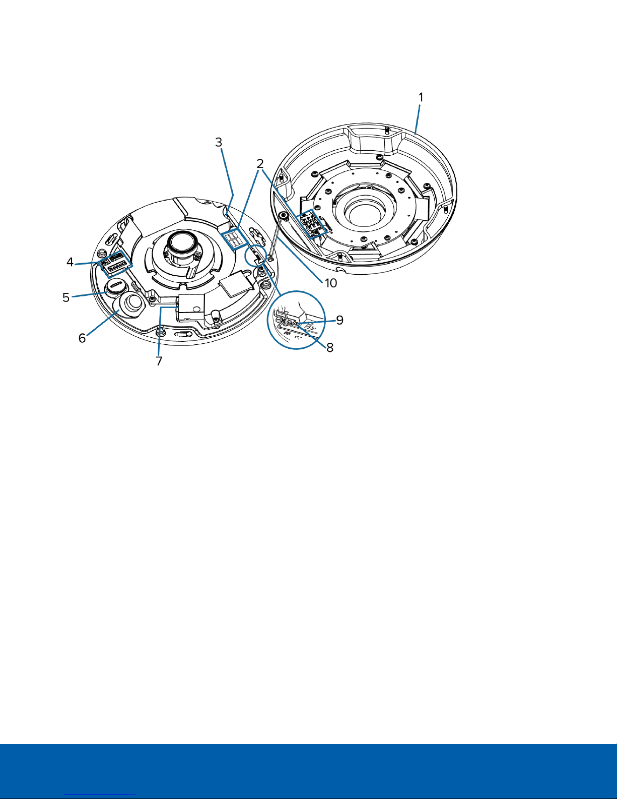
Internal View
1. Dome cover
Vandal resistant dome cover.
2. IR contacts
Align the IR contacts when installing the dome cover to the base. The contacts must be connected to use
the IR illuminators.
3. microSD card slot
Accepts a microSD card for onboard storage.
4. Auxiliary cable connector
Accepts an auxiliary connection for connecting the camera to auxiliary power, audio and I/O devices.
5. Auxiliary cable entry hole
An entry hole for the auxiliary cable.
6. Ethernet cable entry hole
An entry hole for the Ethernet cable.
7. Ethernet port
Accepts an Ethernet connection to a network. Server communication and image data transmission occurs
over this connection. Also receives power when it is connected to a network that provides Power over
Ethernet.
Internal View 2
8. Link LED
Indicates if there is an active connection in the Ethernet port.
9. Connection status LED
Provides information about camera operation. For more information, see LED Indicators on page31.
10. Lanyard
Anchors the dome cover to the camera base.
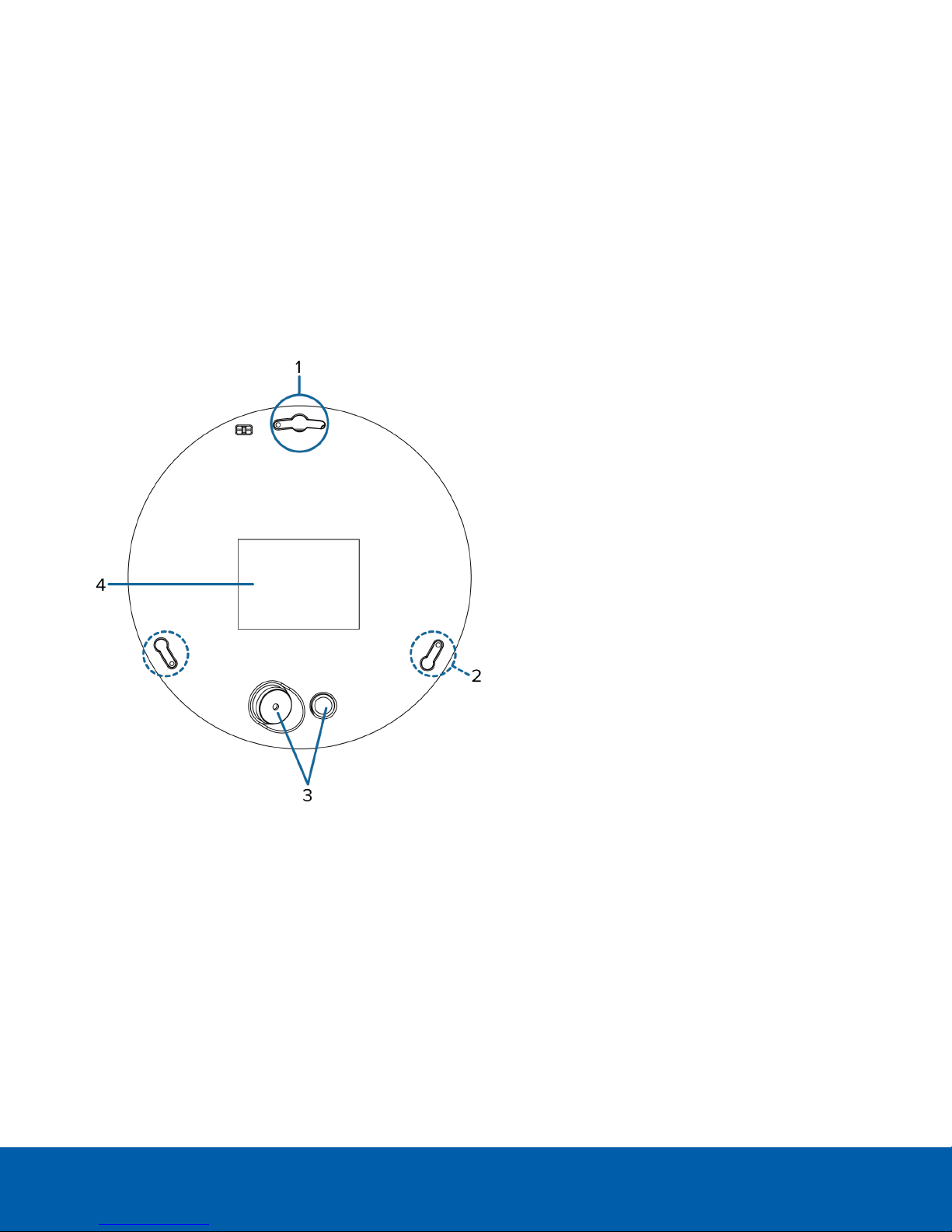
Bottom View
1. Primary mounting slot
The primary mounting point for the camera.
If using the optional mounting bracket or NPT adapter, align the primary camera post (largest diameter
post) with the primary mounting slot.
NOTE: If you are planning to mount the camera on a wall, be aware that the primary mounting slot aligns
with the top of the video image.
2. Secondary mounting slots
Mounting points for the camera.
Bottom View 3
If you are using the optional mounting bracket or NPT adapter, align the camera posts to the mounting
slots.
3. Cable entry holes
An entry holes for the cables required for camera operation.
4. Serial number tag
Device information, product serial number and part number label.
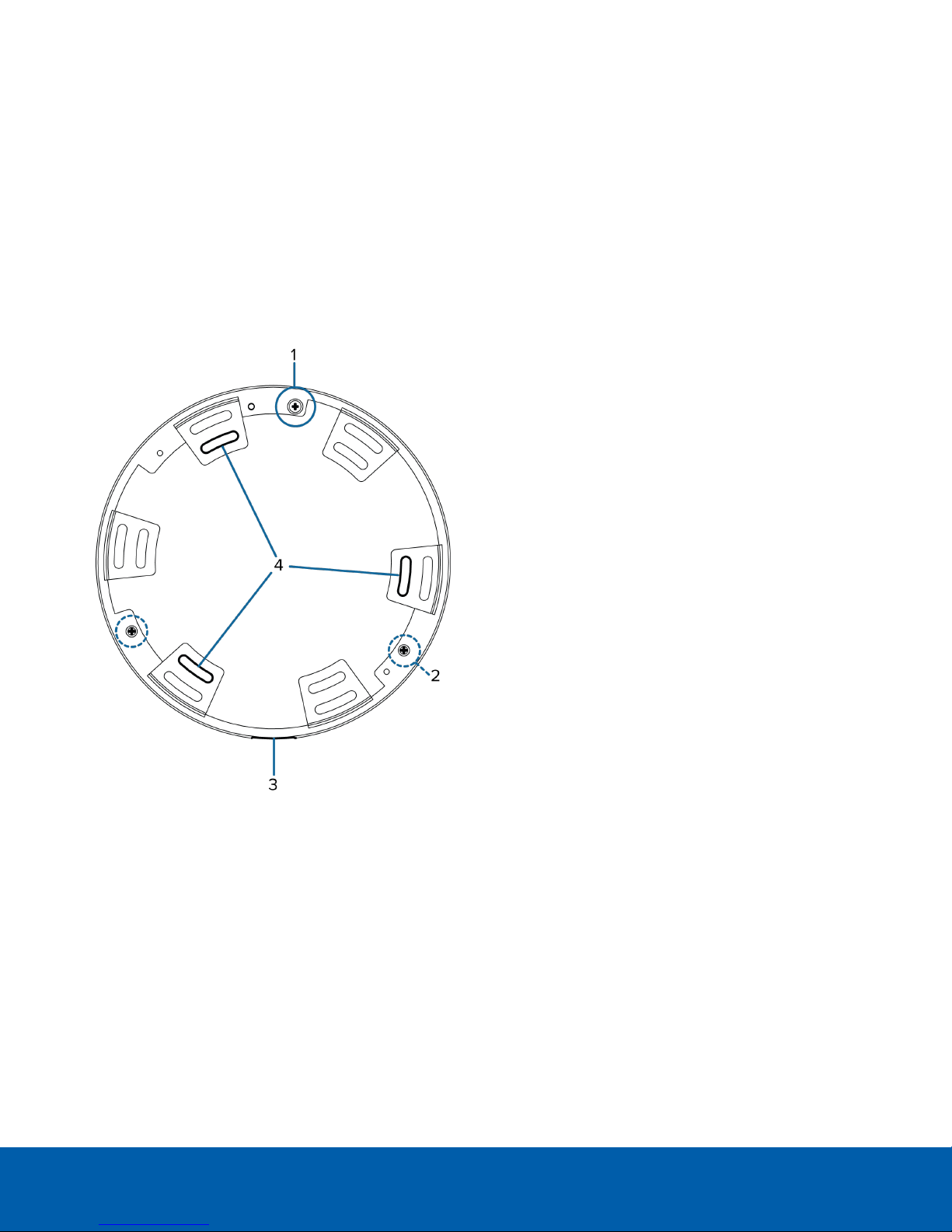
Bracket View
1. Primary camera post
Align the primary camera slot on the optional bracket to the primary mounting post on the dome camera
base.
2. Secondary camera posts
Align the camera posts on the bracket to the mounting slots on the dome camera base.
3. Cable entry notch
An entry notch for network, power and I/O cables.
4. Mounting slots
Mounting points for the optional bracket.
Bracket View 4
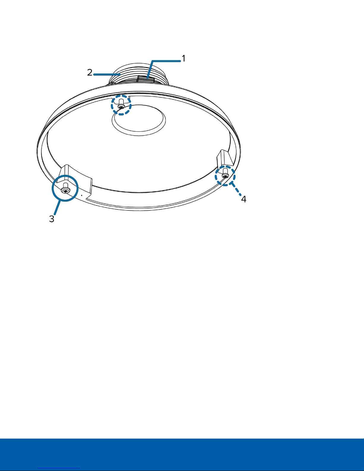
NPT Adapter View
1. Locking nut
Locking nut for securing the NPT adapter to the pipe.
2. 1-1/2” NPT thread mount
Standard female 1-1/2” NPT thread mount for mounting the dome camera to a pole or bracket.
3. Primary camera post
Align the primary camera slot on the NPT adapter to the primary mounting post on the dome camera
base.
4. Secondary camera posts
Align the camera posts on the adapter to the mounting slots on the dome camera base.
NPT Adapter View 5

Installation
Required Tools and Materials
The following tools are required to complete the camera installation but are not included in the camera
package:
l If you will be installing the NPT adapter (H4F-MT-NPTA), you will need a 1-1/2" NPT female to female
adapter.
Camera Package Contents
Ensure the package contains the following:
l Avigilon™ H4 Fisheye Dome Camera
l Camera Base Mounting Template sticker
l Bracket Mounting Template sticker
l Optional mounting bracket
l Torx screwdriver
l Auxiliary cable
l Desiccant bag
l 3 screws and anchors — for securing the camera to the mounting surface.
l 1 x (M3 x 8mm) T10 Torx screw — for securing the camera base to the bracket.
l 2 x (M4 x 8 Philips) machine screws — for securing the bracket to an electrical gang box.
l Rubber washer
l Rubber grommet
If you are using the optional NPT adapter (H4F-MT-NPTA), ensure the package contains the following:
l NPT adapter for the H4 Fisheye Dome Camera
l NPT lock nut
l 1 x (M3 x 8mm) T10 Torx screw — for securing the camera base to the bracket.
l Thread seal tape
Installation Steps
Complete the following steps to install the camera:
Removing the Dome Cover 7
Preparing the Cables 8
(Optional) Configuring microSD Card Storage 10
Installation 6
Mounting the Dome Camera 10
Connecting Cables 24
Assigning an IP Address 25
Accessing the Live VideoStream 26
Installing the Dome Cover 26
Configuring the Camera 27
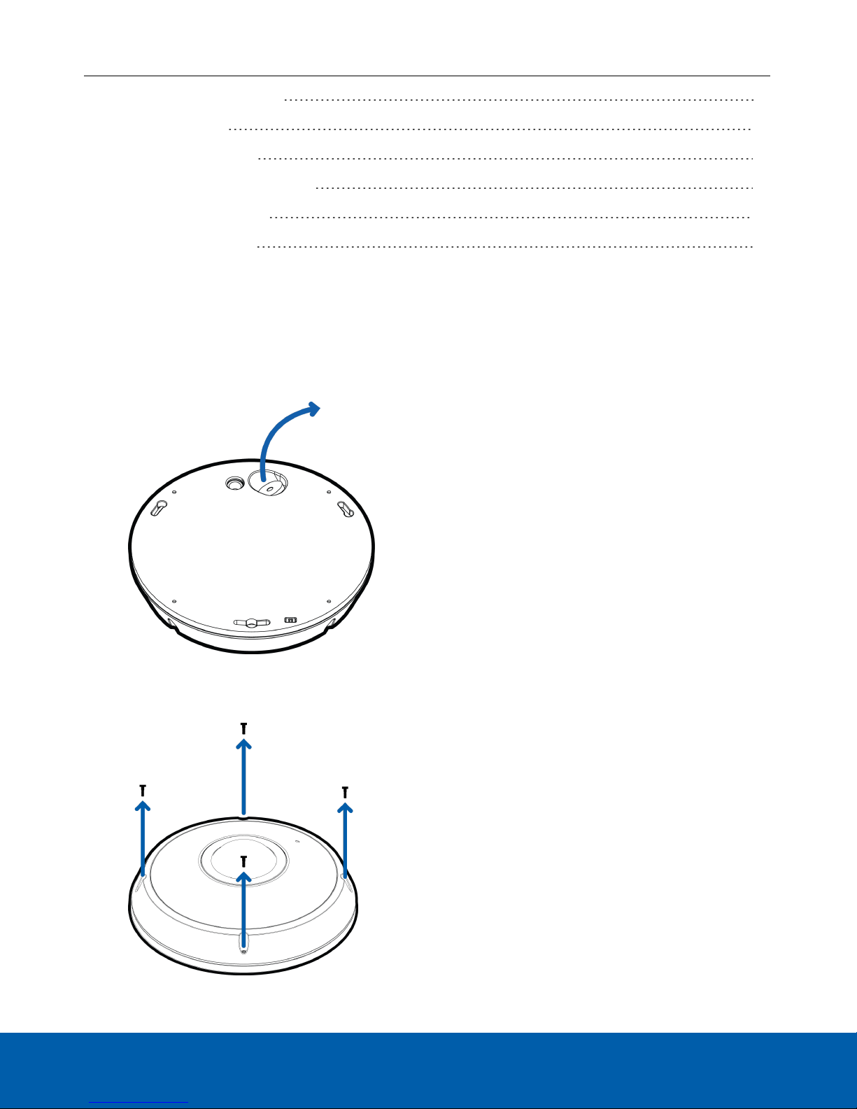
Removing the Dome Cover
1. From the bottom of the dome camera, remove the white plug covering the Ethernet cable entry hole.
Once removed, the plug can be discarded.
Be aware that a vacuum may occur within the camera during shipping. Removing the plug may allow the
dome cover to be removed more easily.
2. Remove the dome cover by loosening the screws that fix the cover to the base. Use the provided Torx
screwdriver to loosen the screws.
Removingthe Dome Cover 7
NOTE: Be careful not to scratch or touch the dome bubble. The resulting marks or fingerprints may affect the
overall image quality. Keep the protective covers on the outside of the dome bubble until the installation is
complete.
Preparing the Cables
Before you connect the cables to the dome camera, you must prepare the cables for installation.
If the dome camera is installed outdoors, it is important that the cables be insulated against the weather.
Provided with the dome camera is a rubber grommet for waterproofing the Ethernet cable, and a rubber washer
for the auxiliary cable.
NOTE: The Ethernet cable must be uncrimped to perform this procedure.
The auxiliary cable that is provided with the dome camera includes an I/O terminal, external power connector,
audio input and audio output connectors. You need to connect the auxiliary cable to the dome camera if any
one of the auxiliary cable connectors is used. For more information about each of the connector options, see
Auxiliary Cable Connections on page29.
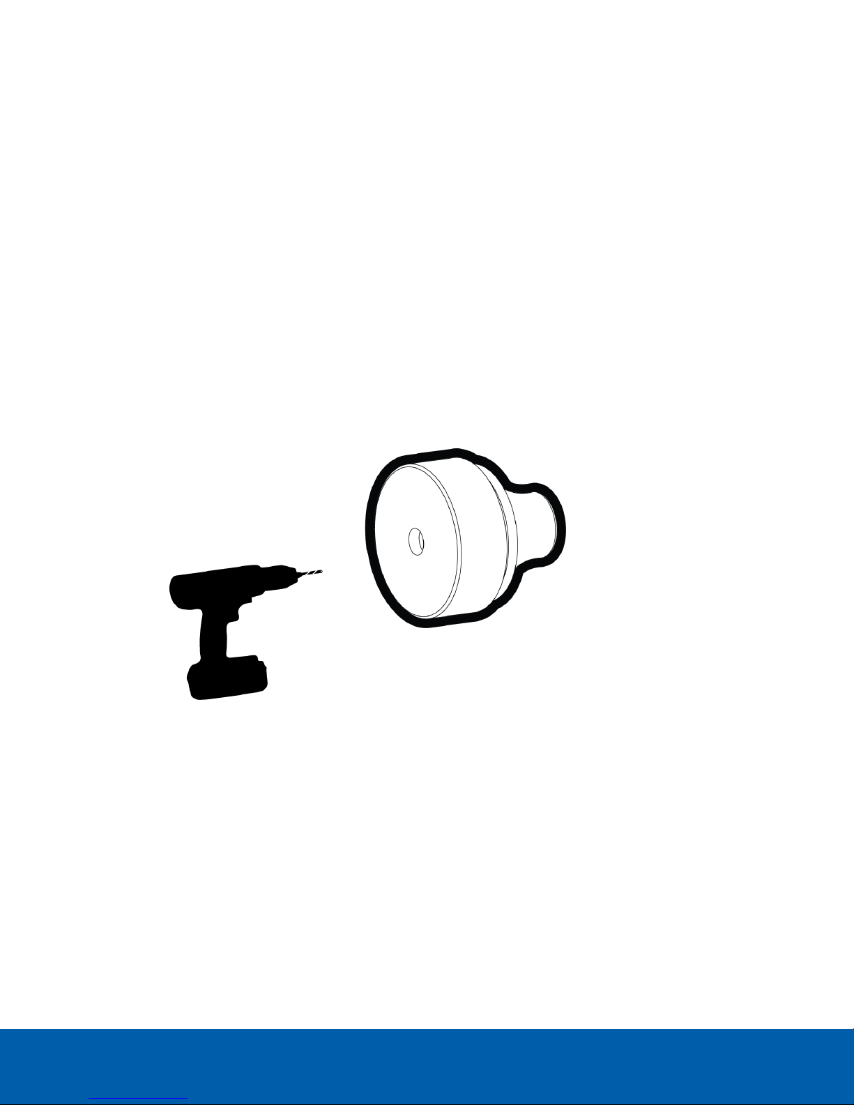
1. Thread the Ethernet cable into the rubber grommet.
a. Drill a hole through the center of the provided rubber grommet.
b. Push the cable through the hole in the rubber grommet.
Ensure the orientation of the cable and grommet matches the following image.
Preparing the Cables 8
 Loading...