

Avigilon 1.0W-H3PTZ-DP20, 2.0W-H3PTZ-DP20 Installation Manual
Installation Guide
Avigilon High Definition H.264 PTZ IP Dome
Camera Models:
1.0W-H3PTZ-DP20 and 2.0W-H3PTZ-DP20
920-0064A-Rev1

i
English
Important Safety Information
This manual provides installation and operation information and
precautions for the use of this dome camera. Incorrect installation
could cause an unexpected fault. Before installing this equipment read
this manual carefully. Please provide this manual to the owner of the
equipment for future use.
• Installation must be performed by qualified personnel only,
and must conform to all local codes.
• This product is intended to be supplied by a UL Listed
Power Unit marked “Class 2” or “LPS” or “Limited Power
Source” with output rated 24 VAC +/- 10%, 55 VA min.;
24 VDC +/- 10%, 44 W min. or Power over Ethernet (PoE)
Plus IEEE802.3at Type 2 compliant Power Sourcing
Equipment (PSE) rated 48-56 VDC, 25.5W min.
• Any external power supply connected to this product may
only be connected to another Avigilon product of the same
model series. External power connections must be
properly insulated.
• Do not connect directly to mains power for any reason.
The Warning symbol indicates the presence of
dangerous voltage within and outside the product
enclosure that may constitute a risk of electric shock,
serious injury or death to persons if proper precautions
are not followed.
The Caution symbol alerts the user to the presence of
hazards that may cause minor or moderate injury to
persons, damage to property or damage to the product
itself if proper precautions are not followed.
Warning — Failure to observe the following instructions
may result in severe injury or death.

ii
English
• Do not install near any heat sources such as radiators,
heat registers, stoves, or other sources of heat.
• Do not subject the cables to excessive stress, heavy loads
or pinching.
• Do not open or disassemble the device. There are no user
serviceable parts.
• Refer all servicing to qualified personnel.
Servicing may be required when the device has been
damaged (such as from a liquid spill or fallen objects), has
been exposed to rain or moisture, does not operate
normally, or has been dropped.
• Do not use strong or abrasive detergents when cleaning
the device body.
• Use only accessories recommended by Avigilon.
Caution — Failure to observe the following instructions
may result in injury or damage to the dome camera.
iii
English
Regulatory Notices
This device complies with part 15 of the FCC Rules. Operation is
subject to the following two conditions: (1) This device may not cause
harmful interference, and (2) this device must accept any interference
received, including interference that may cause undesired operation.
This Class B digital apparatus complies with Canadian ICES-003.
FCC Notice
This equipment has been tested and found to comply with the limits for
a Class B computing device pursuant to Subpart B of Part 15 of FCC
rules, which are designed to provide reasonable protection against
such interference when operated in a commercial environment.
Operation of this equipment in a residential area is likely to cause
interference, in which case the user at his/her own expense will be
required to take whatever measures may be required to correct the
interference.
Changes or modifications made to this equipment not expressly
approved by Avigilon Corporation or parties authorized by Avigilon
Corporation could void the user’s authority to operate this equipment.
Disposal and Recycling Information
When this product has reached the end of its useful life, please
dispose of it according to your local environmental laws and
guidelines.
European Union:
This symbol means that according to local laws and
regulations your product should be disposed of separately
from household waste. When this product reaches its end of
life, take it to a collection point designated by local
authorities. Some collection points accept products for free.
The separate collection and recycling of your product at the
time of disposal will help conserve natural resources and
ensure that it is recycled in a manner that protects human
health and the environment.

iv
English
Other Notices
Compilation and Publication Notice
This manual has been compiled and published covering the latest
product descriptions and specifications. The contents of this manual
and the specifications of this product are subject to change without
notice. Avigilon reserves the right to make changes without notice in
the specifications and materials contained herein and shall not be
responsible for any damages (including consequential) caused by
reliance on the materials presented, including but not limited to
typographical and other errors relating to the publication.
Intellectual Property Notice
No license is granted by implication or otherwise under any industrial
design, industrial design rights, patent, patent rights, or copyrights of
Avigilon Corporation or its licensors. Trademarks and registered
trademarks are the property of their respective owners.

English
Table of Contents
Overview . . . . . . . . . . . . . . . . . . . . . . . . . . . . . . 1
Front View . . . . . . . . . . . . . . . . . . . . . . . . . . . . . . . . 1
Top View . . . . . . . . . . . . . . . . . . . . . . . . . . . . . . . . . 2
Pendant Mount Adapter . . . . . . . . . . . . . . . . . . . . . . 3
Installation . . . . . . . . . . . . . . . . . . . . . . . . . . . . 4
Camera Package Contents . . . . . . . . . . . . . . . . . . . 4
Installation Steps . . . . . . . . . . . . . . . . . . . . . . . . . . . 4
Installing the Mount Adapter . . . . . . . . . . . . . 4
Connecting Cables . . . . . . . . . . . . . . . . . . . . 7
Securing the PTZ Dome Camera . . . . . . . . . 8
Assigning an IP Address . . . . . . . . . . . . . . . 8
Accessing the Live Video Stream . . . . . . . . . 9
For More Information . . . . . . . . . . . . . . . . . . 9
Cable Connections . . . . . . . . . . . . . . . . . . . . . 10
Connecting External Power . . . . . . . . . . . . . . . . . . 10
Connecting to External Devices . . . . . . . . . . . . . . 11
LED Indicators . . . . . . . . . . . . . . . . . . . . . . . . 12
Reset to Factory Default Settings . . . . . . . . . 13
Setting the IP Address Through the ARP/Ping
Method . . . . . . . . . . . . . . . . . . . . . . . . . . . . . . . 14
Specifications . . . . . . . . . . . . . . . . . . . . . . . . . 15
Limited Warranty & Technical Support . . . . 16

English

1
English
Overview
Front View
Feature Description
Serial Number Label Product serial number and part number
label.
Link LED Indicates if there is an active connection
in the Ethernet port.
Connection Status LED Provides information about device
operation. See the section about LED
indicators for more information.
Connection Status LED
Serial Number Label
Link LED
2
English
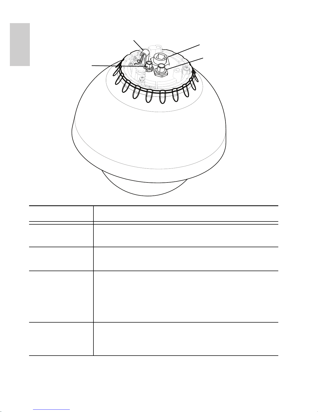
Top View
Feature Description
External Power Accepts an external power connection when Power
over Ethernet is not available.
Lanyard Anchor The safety lanyard attaches to the anchor to
prevent the camera from falling during installation.
Ethernet Port Accepts an Ethernet connection to a network.
Server communication and image data
transmission occurs over this connection. Also
receives power when it is connected to a network
that provides Power over Ethernet.
External I/O Provides connections to external input/output and
audio/video devices. See the section about
connecting external devices for more information.
External Power
Ethernet Port
External I/O
Lanyard Anchor
3
English
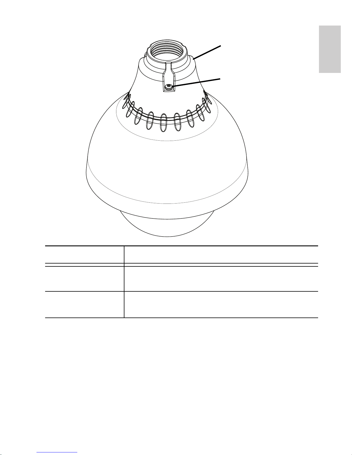
Pendant Mount Adapter
Feature Description
1-1/2” NPT Mount
Adapter
Standard 1-1/2” NPT adapter for mounting the
dome camera to a pendant mount bracket.
Tamper Proof
Screws
TORX tamper-resistant captive screws to fix the
dome camera to the NPT adapter.
1 1/2” NPT Mount Adapter
Tamper Proof Screws

4
English
Installation
Camera Package Contents
Ensure the package contains the following:
• Avigilon High Definition PTZ Dome Camera
• 1 ½” NPT Adapter
• T20 TORX tamper resistant key
• Teflon Sealing Tape
• RJ-45 crimp-on plug and weather-resistant housing
• Wiring harnesses (External Power and External I/O)
Installation Steps
Complete the following procedures to install the dome camera.
1. Installing the Mount Adapter on page 4
2. Connecting Cables on page 7
3. Securing the PTZ Dome Camera on page 8
4. Assigning an IP Address on page 8
5. Accessing the Live Video Stream on page 9
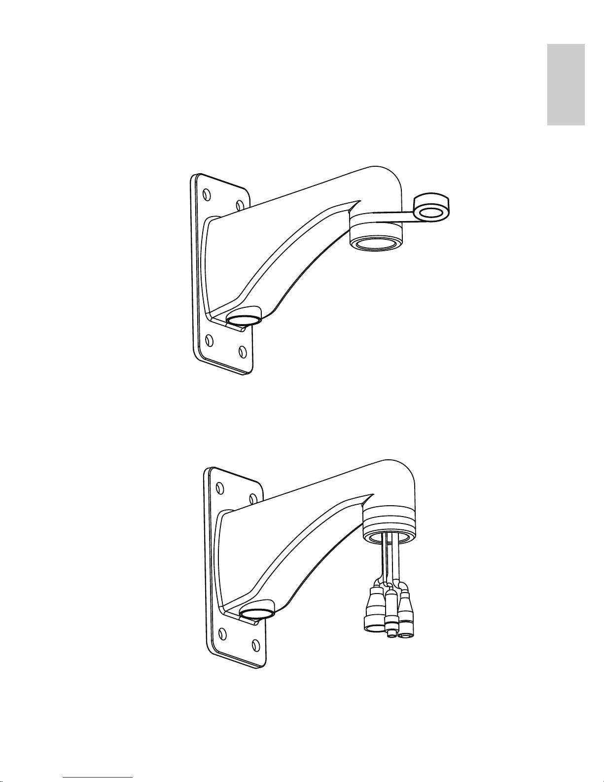
Installing the Mount Adapter
The dome camera must be mounted on a 1-1/2” NPT male threaded
wall or ceiling mounting bracket. The mounting bracket is not included
in the camera package.
1. Wrap the thread of the mounting bracket with the supplied
Teflon sealing tape to create a water tight seal around the
camera connection. There should be a minimum of three
turns around the entire threaded surface.
Caution — The dome camera must be mounted as
instructed below or problems with moisture may arise and
will not be covered by the dome camera warranty.
5
English
When applying the Teflon sealing tape, be sure to wrap in
the same direction that the mount will be tightened. This
will ensure the tape does not unravel when installing the
mating parts together.
Tip: Always apply Teflon tape to threaded mounts to help prevent the
threads from binding
2. Pull the required cables through the mounting bracket then
install the supplied connectors and wire assemblies. See
Cable Connections for wiring details.
6
English
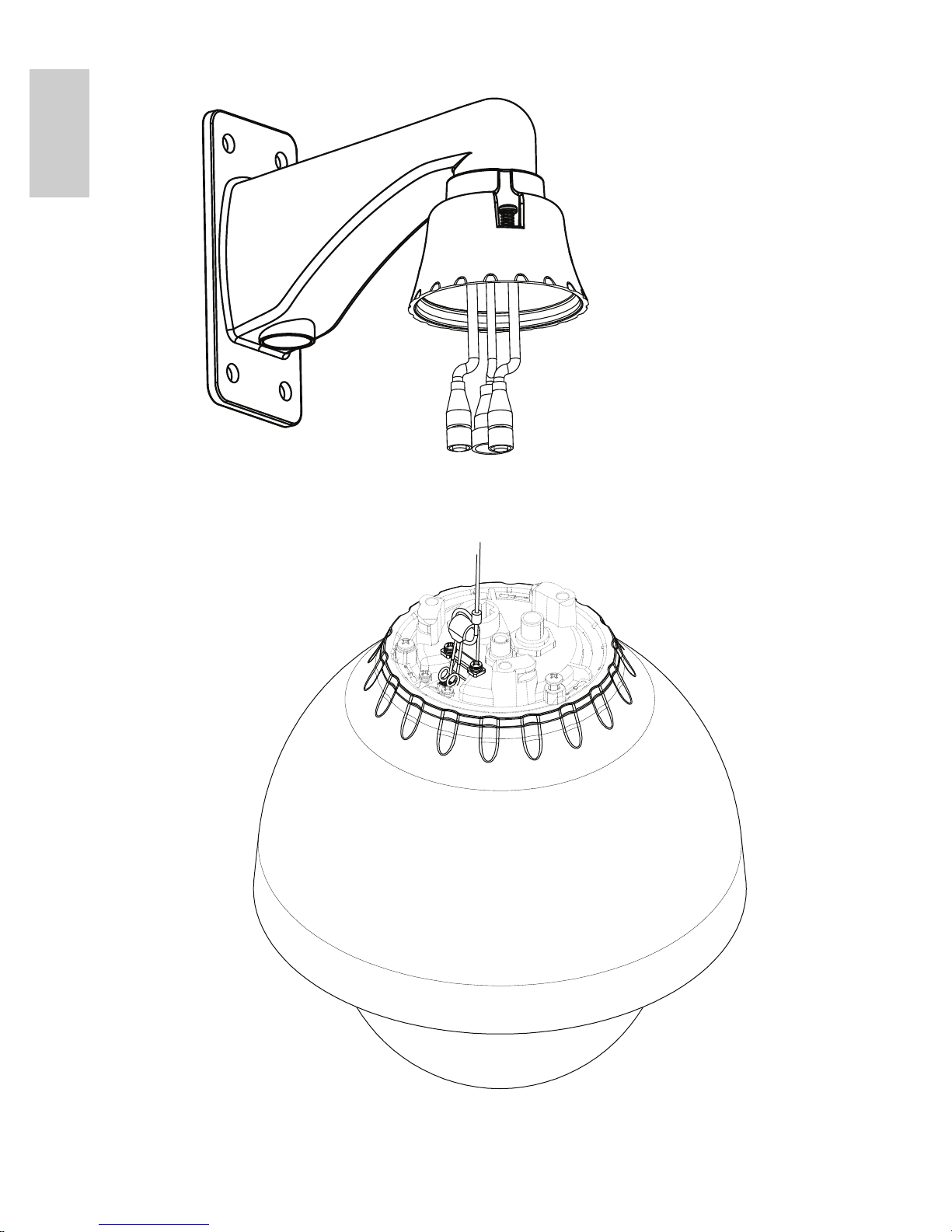
3. Install the 1 1/2” NPT mount adapter.
4. Connect the safety lanyard from inside the NPT mount
adapter to the anchor on the PTZ dome camera.

7
English
Connecting Cables
Refer to the camera’s Top View on page 2 for the location of the
different connectors.
Make sure the safety lanyard is connected to the PTZ dome camera
before you complete the following cable connections:
1. If there are external input or output devices that need to be
connected to the camera (for example: door contacts,
relays, analog video, speakers, etc), connect the devices
to the camera I/O connector cable.
For more information, see Connecting to External Devices.
2. Connect power using one of the following methods:
• Power over Ethernet (PoE) Plus IEEE 802.3at
Class 4 — Connect a PoE Plus compliant injector
or switch to the Ethernet network cable.
• External Power — Connect an external “Class 2” or
“LPS” or “Limited Power Source” with output rated
24 VAC +/- 10%, 55 VA minimum or 24 VDC
+/- 10%, 44 W minimum.
For more information, see Connecting External
Power.
3. Connect the Ethernet Port (RJ45 connector) to a network
using an Ethernet network cable. The Link LED will turn on
once a network link has been established.
4. Check that the Connection Status LED indicates the
correct state.
For more information, see LED Indicators.
8
English
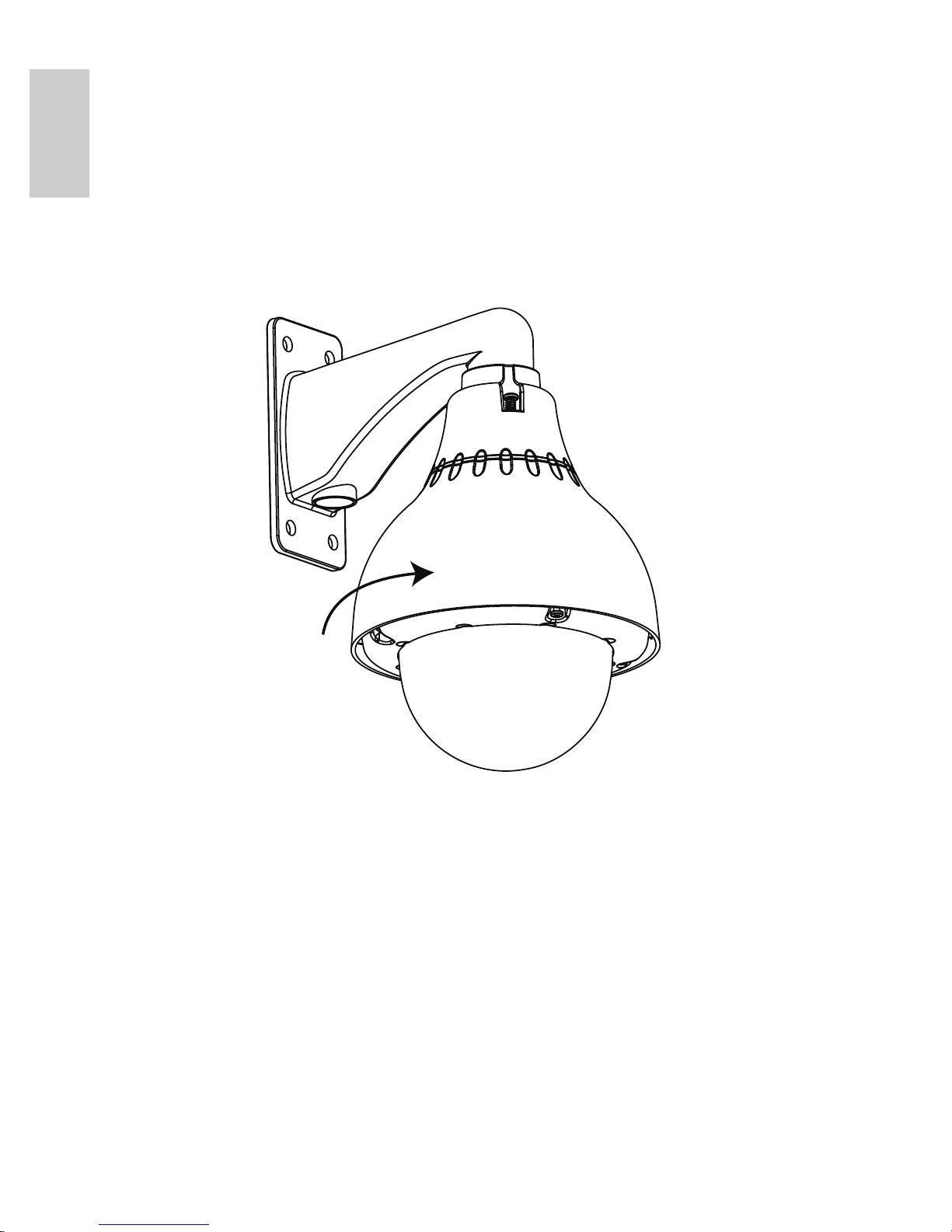
Securing the PTZ Dome Camera
After the cable connections have been made, secure the PTZ dome
camera to the mount.
1. Push the PTZ dome camera into the 1 1/2” NPT mount
adapter then twist until it locks into place.
NOTE: Be careful not to trap any cables between the dome
camera housing and the mount adapter.
2. Use the tamper resistant key included with the dome
camera to tighten the three tamper proof screws in the
mount adapter.
Assigning an IP Address
The camera automatically obtains an IP address by default. Once
connected to a network, it attempts to locate and obtain an IP address
from a DHCP server. If this fails, Zero Configuration Networking
(Zeroconf) is used to choose an IP address. When the IP address is
set using Zeroconf, the IP address is in the 169.254.0.0/16 subnet.

9
English
The IP address settings can be changed using one of the following
methods:
• (Recommended) Avigilon Camera Installation Tool
software application.
• Camera's web browser interface:
http://<camera IP address>/
• ARP/Ping method. For more information, see Setting the
IP Address through the ARP/Ping Method.
• Network Video Management software application (for
example, Avigilon Control Center).
NOTE: The default camera username is admin and the default
password is admin.
Accessing the Live Video Stream
Live video stream can be viewed using one of the following methods:
• (Recommended) Avigilon Camera Installation Tool
software application.
• Camera's web browser interface:
http://<camera IP address>/.
• Network Video Management software application (for
example, Avigilon Control Center).
NOTE: The default camera username is admin and the default
password is admin.
For More Information
Additional information about setting up and using the device is
available in the following guides:
• Avigilon Camera Installation Tool User Guide
• Avigilon Control Center Client User Guide
• Avigilon High Definition H.264 IP Camera User Guide
The manuals are available on the Avigilon website:
http://avigilon.com/
support/manuals/.
10
English
Cable Connections
Connecting External Power
NOTE: This procedure is not required if Power over Ethernet (PoE) is
used.
If PoE is not available, the dome camera can be powered with 24 VAC
or 24 VDC through the removable power connector:
1. Remove as much insulation as required to splice the
supplied power connector to the power adapter wires (not
included).
Do not nick or damage the wires.
2. Remove the dummy plug from the power receptacle on the
device.
See the diagram on page 2 for the location of the external
power receptacle.
3. Attach the power connector to the receptacle on the
camera.
Table: Power Connector Pin Details
Pin Wire Color Function
1 Brown Power, accepts either polarity
2 Not used Not used
3 Blue Power, accepts either polarity
Warning — This product is intended to be supplied by a UL
Listed Power Unit marked “Class 2” or “LPS” or “Limited
Power Source” with output rated 24 VAC +/- 10%, 55 VA
min. or 24 VDC +/- 10%, 44 W min.
11
English
Connecting to External Devices
External devices, including audio and video devices, are connected to
the camera through the I/O cable. The pinout for the I/O connector is
shown in the following table.
The camera can be connected to an external microphone, speaker
and video monitor through the I/O connector.
NOTE: The camera only supports line level mono audio input and an
NTSC or PAL video output.
The video output signal is determined by the camera flicker control
setting. When the camera flicker control is set to 60 Hz, the video
output signal is NTSC. When the flicker control is set to 50 Hz, the
video output signal is PAL. Use the Avigilon Camera Installation Tool
to configure the camera’s flicker control in the Image and Display
setup.
Table: External I/O Connector
Pin Wire Color Description
1 White Audio/video analog ground return
2 Brown Analog audio input
3 Green Analog audio output
4 Yellow Analog video output
5 Grey Relay ground return
6 Pink Relay output 1
7 Blue Relay output 2
8 Light Red Relay input 1
9 Orange Relay input 2
10 Dark Red +12 V output for relay drive
11 Black Not connected
12 Purple
12
English
LED Indicators
Once the camera is connected to the network, the Connection Status
LEDs will display the camera’s progress in connecting to the Network
Video Management software.
The following table describes what the LEDs indicate:
Table: LED Indicators
Connection
State
Connection
Status LED
Description
Obtaining IP
Address
One short
flash every
second
Attempting to obtain an IP address.
Discoverable Two short
flashes every
second
Obtained an IP address but is not
connected to the Network Video
Management software.
Upgrading
Firmware
Two short
flashes and
one long flash
every second
Updating the firmware.
Connected On Connected to the Network Video
Management software.
13
English
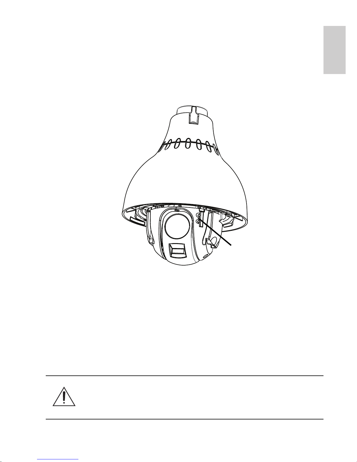
Reset to Factory Default Settings
If the camera no longer functions as expected, you can choose to
restore the camera to its factory default settings.
Use the firmware revert button to reset the camera.
NOTE: Be careful not to scratch the dome bubble.
Figure: The firmware revert microswitch between the status LEDs.
1. Ensure the camera is powered on.
2. Remove the dome cover by loosening the 4 tamper-proof
screws that fix the cover to the base. The tamper resistant
key included with the dome camera can be used to loosen
the screws
3. Using a straightened paperclip or similar tool, gently press
and hold the firmware revert microswitch for two seconds.
4. Re-install the dome cover.
Caution — Do not apply excessive force. Inserting the tool
too far will damage the device.
Firmware Revert Button

14
English
Setting the IP Address
Through the ARP/Ping Method
Complete the following steps to configure the camera to use a specific
IP address:
1. Locate and copy down the MAC Address (MAC) listed on
the Serial Number Tag for reference.
2. Open a Command Prompt window and enter the following
commands:
a. arp -s <New Camera IP Address> <Camera
MAC Address>
For example: arp -s 192.168.1.10 00-18-
85-12-45-78
b. ping -l 123 -t <New Camera IP Address>
For example: ping -l 123 -t 192.168.1.10
3. Reboot the camera.
4. Close the Command Prompt window when you see the
following message:
Reply from <New Camera IP Address>: ...

15
English
Specifications
Camera
Lens 4.7-94mm, 20x zoom, F1.6 and automatic focus
Network
Network 100Base-TX
Cabling Type CAT5
Connector RJ-45
API ONVIF compliant (
www.onvif.org)
Security Password protection, HTTPS encryption, digest authentication, WS authentication,
user access log
Protocols IPv4, HTTP, HTTPS, SOAP, DNS, NTP, RTSP, RTCP, RTP, TCP, UDP, IGMP, ICMP,
DHCP, Zeroconf, ARP
Streaming Protocols RTP/UDP, RTP/UDP multicast, RTP/RTSP/TCP, RTP/RTSP/HTTP/TCP, RTP/
RTSP/HTTPS/TCP, HTTP
Mechanical
Dimensions ØxH 226 mm x 299.77mm, 8.9” x 11.8”
Weight 3.9 kg (8.6 lbs)
Dome Bubble Acrylic, clear
Body Aluminum
Housing Pendant mount
Finish Powder coat, cool gray 2
Tilt 186°, 0.05 - 360°/sec
Pan 360°, endless, 0.05 - 450°/sec
Presets 100 named presets
Tours 10 named guard tours
Electrical
Power Source VAC: 24 V +/- 10%
VDC: 24 V, +/- 10%
PoE: IEEE802.3at Class 4 PoE Plus compliant
Power Consumption 55 VA with AC power
44 W with DC power
25.5 W with IEEE 802.3at Class 4 PoE Plus
Power Connector Waterproof 2-pin connector
Environmental
Operating Temperature -45 °C to + 50 °C (-50 °F to 122 °F) with external power
-30 °C to + 50 °C (-22 °F to 122 °F) with IEEE 802.3at Class 4 PoE Plus power
Storage Temperature -10 °C to +70 °C (14 °F to 158 °F)
Humidity 20 - 80% Relative humidity (non-condensing)
Certifications
Safety UL 60950 CVV
CSA 60950 C-Tick
CB Scheme
Environmental IK09 Impact Rating Meets IP66 Weather Rating
Electromagnetic
Emissions
FCC Part 15 Subpart B Class B
IC ICES-003 Class B EN 55022 Class B
Electromagnetic
Immunity
EN 55024 Class B EN 61000-4-2 EN 61000-4-3
EN 61000-4-4 EN 61000-4-5 EN 61000-4-6
EN 61000-4-11

16
English
Limited Warranty & Technical Support
Avigilon warrants to the original consumer purchaser, that this product will be
free of defects in material and workmanship for a period of 3 years from date of
purchase. The warranty period shall be limited to a period of 1 year from date of
purchase for all moving parts (including but not limited to fans, pan/tilt motors,
lens motors, irises and lens assemblies).
The manufacturer’s liability hereunder is limited to replacement of the product,
repair of the product or replacement of the product with repaired product at the
discretion of the manufacturer. This warranty is void if the product has been
damaged by accident, unreasonable use, neglect, tampering or other causes
not arising from defects in material or workmanship. This warranty extends to
the original consumer purchaser of the product only.
AVIGILON DISCLAIMS ALL OTHER WARRANTIES EXPRESSED OR
IMPLIED INCLUDING, WITHOUT LIMITATION, ANY IMPLIED WARRANTIES
OF MERCHANTABILITY OR FITNESS FOR A PARTICULAR PURPOSE,
EXCEPT TO THE EXTENT THAT ANY WARRANTIES IMPLIED BY LAW
CANNOT BE VALIDLY WAIVED.
No oral or written information, advice or representation provided by Avigilon, its
distributors, dealers, agents or employees shall create another warranty or
modify this warranty. This warranty states Avigilon’s entire liability and your
exclusive remedy against Avigilon for any failure of this product to operate
properly.
In no event shall Avigilon be liable for any indirect, incidental, special,
consequential, exemplary, or punitive damages whatsoever (including but not
limited to, damages for loss of profits or confidential or other information, for
business interruption, for personal injury, for loss of privacy, for failure to meet
any duty including of good faith or of reasonable care, for negligence, and for
any other pecuniary or other loss whatsoever) arising from the use of or inability
to use the product, even if advised of the possibility of such damages. Since
some jurisdictions do not allow the above limitation of liability, such limitation
may not apply to you.
This Limited Warranty gives you specific legal rights and you may also have
other rights which vary from jurisdiction to jurisdiction.
Warranty service and technical support can be obtained by
contacting Avigilon Technical Support by phone at
1.888.281.5182 or via email at support@Avigilon.com.
Guide d'installation
Modèles de caméra dôme IP H.264 PTZ
haute définition Avigilon :
1.0W-H3PTZ-DP20 et 2.0W-H3PTZ-DP20

i
Français
Informations de sécurité
importantes
Ce manuel fournit des informations d'installation et d'exploitation, ainsi que
des précautions d'utilisation pour la caméra dôme. Une installation
incorrecte peut entraîner une défaillance imprévue. Avant d'installer cet
équipement, lisez attentivement ce manuel. Veuillez remettre ce manuel au
propriétaire de l'équipement pour une utilisation ultérieure.
Le symbole d'avertissement indique la présence de tensions
dangereuses, à l'intérieur et à l'extérieur du boîtier du produit,
susceptibles de générer un risque de choc électrique, de
blessure grave, voire de décès, si des précautions appropriées
ne sont pas prises.
Le symbole Attention alerte l'utilisateur sur la présence de
dangers susceptibles d'infliger aux personnels des blessures
mineures à modérées, d'endommager des biens ou le produit
lui-même si des précautions appropriées ne sont pas prises.
• L'installation doit être effectuée par un personnel qualifié
uniquement et doit être en conformité avec tous les codes
locaux.
• Ce produit doit être alimenté par une alimentation répertoriée
UL et portant le marquage "Classe 2", "LPS" ou "Limited Power
Source", d'une capacité de sortie nominale de 24 VCA +/10%, 55 VA minimum, 24 VCC +/- 10%, 44 W minimum ou une
alimentation PSE (Power Sourcing Equipment) conforme à la
norme PoE (Power over Ethernet) Plus IEEE802.3at Type 2,
d'une tension de 48 à 56 VCC, 25,5W minimum.
• Toute alimentation externe connectée à ce produit ne peut être
connectée qu'à un autre produit Avigilon de la même gamme
de modèles. Les connexions à des alimentations externes
doivent être correctement isolées.
Avertissement — Le non-respect des instructions suivantes est
susceptible d'entraîner des blessures graves voire le décès.
ii
Français
• Pour quelque raison que ce soit, ne connectez pas
l'équipement directement au secteur.
• N'effectuez aucune installation à proximité de sources de
chaleur, telles que radiateurs, bouches de chaleur ou poêles.
• Ne soumettez pas les câbles à des tensions, des charges ou
des pincements excessifs.
• N'ouvrez pas l'équipement, ne le démontez pas. Il ne contient
aucune pièce sur laquelle l'utilisateur peut intervenir.
• Pour toute intervention, contactez un personnel qualifié.
Une intervention peut se révéler nécessaire lorsque
l'équipement est endommagé (par exemple, par le
renversement d'un liquide ou la chute d'un objet), lorsqu'il a été
exposé à la pluie ou à l'humidité (présence de moisissure),
lorsqu'il ne fonctionne pas normalement ou lorsqu'il a chuté.
• N'utilisez pas de détergents puissants ou abrasifs lorsque vous
nettoyez le corps de l'équipement.
• Utilisez uniquement les accessoires recommandés par
Avigilon.
Attention — Le non-respect des instructions suivantes est
susceptible d'entraîner des blessures ou d'endommager la
caméra dôme.
iii
Français
Avis concernant la réglementation
Cet équipement est conforme à section 15 des règles FCC. Son
exploitation est sujette aux deux conditions suivantes : (1) Cet équipement
ne risque pas de générer d'interférences nuisibles et (2) cet équipement
doit accepter toute interférence reçue, y compris celles susceptibles
d'induire un fonctionnement indésirable.
Cet équipement numérique de Classe B est conforme à la norme
canadienne ICES-003.
Notice FCC
Cet équipement a été testé et déclaré conforme aux limitations relatives à
un appareil numérique de classe B, en vertu de la Sous-section B de la
Section 15 des règles de la FCC. Ces limitations visent à assurer une
protection raisonnable contre les interférences dans le cadre d'une
exploitation de l'équipement dans un environnement commercial.
L'exploitation de cet équipement dans une zone résidentielle est
susceptible de générer des interférences nuisibles, auquel cas l'utilisateur
sera tenu de prendre toute mesure nécessaire pour remédier à ces
interférences.
Tout changement ou modification apporté à cet équipement non
expressément approuvé par Avigilon Corporation ou des tiers autorisés par
Avigilon Corporation pourrait annuler l'autorisation accordée à l'utilisateur
d'utiliser cet équipement.
Informations sur la mise au rebut et le recyclage
Lorsque ce produit aura atteint la fin de sa vie utile, veuillez le mettre au
rebut conformément aux directives et à la législation locales sur
l'environnement.
Union européenne :
Ce symbole signifie que, conformément aux lois et aux réglementations
locales, votre produit doit être mis au rebut hors déchets ménagers.
Lorsque ce produit aura atteint la fin de sa vie utile, portez-le à un point
de collecte désigné par les autorités locales. Certains points de collecte
acceptent gratuitement les produits. La collecte et le recyclage séparés
de votre produit au moment de la mise au rebut contribuent à conserver
les ressources naturelles et garantissent que le produit est recyclé de
sorte à protéger la santé humaine et l'environnement.

iv
Français
Autres notices
Notice sur la compilation et la publication
Ce manuel a été compilé et publié en couvrant les spécifications et
descriptions de produit les plus récentes. Le contenu de ce manuel et les
spécifications de ce produit sont sujets à modifications sans avis préalable.
Avigilon se réserve le droit d'apporter des modifications sans avis préalable
aux spécifications et informations présentées dans le présent manuel.
Avigilon ne saurait être tenu responsable de tout dommage (notamment
accessoire) causé par le fait de se fier aux informations présentées,
notamment mais sans s'y limiter, en termes d'erreurs typographiques et
d'autres erreurs liées à la publication.
Notice de propriété intellectuelle
Aucun licence n'est accordée par implication ou autre action dans le cadre
de toute conception industrielle, de droits de conception industriels, de
brevet et droits de brevet, ou de droits de reproduction (copyrights)
d'Avigilon Corporation ou de ses concédants de licence. Les marques
commerciales et les marques déposées sont la propriété de leurs
détenteurs respectifs.
 Loading...