

Page 1
Installation Guide
Avigilon High Definition H.264 IP
Micro Dome Camera Models:
1.0-H3M-DO1 and 2.0-H3M-DO1
920-0067A-Rev2
Page 2

Page 3
i
English
Important Safety Information
This manual provides installation and operation information and
precautions for the use of this dome camera. Incorrect installation
could cause an unexpected fault. Before installing this equipment read
this manual carefully. Please provide this manual to the owner of the
equipment for future use.
• Installation must be performed by qualified personnel only,
and must conform to all local codes.
• This product is intended to be supplied by a UL Listed
Power over Ethernet (PoE) PSE, rated 48 VDC, 4 W min.
• Do not install near any heat sources such as radiators,
heat registers, stoves, or other sources of heat.
• Do not subject the cables to excessive stress, heavy loads
or pinching.
• Do not open or disassemble the device. There are no user
serviceable parts.
The Warning symbol indicates the presence of dangerous
voltage within and outside the product enclosure that may
constitute a risk of electric shock, serious injury or death to
persons if proper precautions are not followed.
The Caution symbol alerts the user to the presence of hazards
that may cause minor or moderate injury to persons, damage to
property or damage to the product itself if proper precautions
are not followed.
Warning — Failure to observe the following instructions
may result in severe injury or death.
Caution — Failure to observe the following instructions
may result in injury or damage to the dome camera.
Page 4

ii
English
• Refer all servicing to qualified personnel.
Servicing may be required when the device has been
damaged (such as from a liquid spill or fallen objects), has
been exposed to rain or moisture, does not operate
normally, or has been dropped.
• Do not use strong or abrasive detergents when cleaning
the device body.
• Use only accessories recommended by Avigilon.
Page 5
iii
English
Regulatory Notices
This device complies with part 15 of the FCC Rules. Operation is
subject to the following two conditions: (1) This device may not cause
harmful interference, and (2) this device must accept any interference
received, including interference that may cause undesired operation.
This Class B digital apparatus complies with Canadian ICES-003.
FCC Notice
This equipment has been tested and found to comply with the limits for
a Class B computing device pursuant to Subpart B of Part 15 of FCC
rules, which are designed to provide reasonable protection against
such interference when operated in a commercial environment.
Operation of this equipment in a residential area is likely to cause
interference, in which case the user at his/her own expense will be
required to take whatever measures may be required to correct the
interference.
Changes or modifications made to this equipment not expressly
approved by Avigilon Corporation or parties authorized by Avigilon
Corporation could void the user’s authority to operate this equipment.
Disposal and Recycling Information
When this product has reached the end of its useful life, please
dispose of it according to your local environmental laws and
guidelines.
European Union:
This symbol means that according to local laws and regulations your
product should be disposed of separately from household waste. When
this product reaches its end of life, take it to a collection point
designated by local authorities. Some collection points accept products
for free. The separate collection and recycling of your product at the
time of disposal will help conserve natural resources and ensure that it
is recycled in a manner that protects human health and the
environment.
Page 6

iv
English
Other Notices
Compilation and Publication Notice
This manual has been compiled and published covering the latest
product descriptions and specifications. The contents of this manual
and the specifications of this product are subject to change without
notice. Avigilon reserves the right to make changes without notice in
the specifications and materials contained herein and shall not be
responsible for any damages (including consequential) caused by
reliance on the materials presented, including but not limited to
typographical and other errors relating to the publication.
Intellectual Property Notice
No license is granted by implication or otherwise under any industrial
design, industrial design rights, patent, patent rights, or copyrights of
Avigilon Corporation or its licensors. Trademarks and registered
trademarks are the property of their respective owners.
Page 7

English
Table of Contents
Overview . . . . . . . . . . . . . . . . . . . . . . . . . . . . . . 1
Front View . . . . . . . . . . . . . . . . . . . . . . . . . . . . . . . . 1
Top View . . . . . . . . . . . . . . . . . . . . . . . . . . . . . . . . . 2
Installation . . . . . . . . . . . . . . . . . . . . . . . . . . . . 3
Required Tools and Materials . . . . . . . . . . . . . . . . . 3
Camera Package Contents . . . . . . . . . . . . . . . . . . . 3
Installation Steps . . . . . . . . . . . . . . . . . . . . . . . . . . . 3
Adding the Mounting Holes . . . . . . . . . . . . . 4
Connecting PoE . . . . . . . . . . . . . . . . . . . . . . 5
Assigning an IP Address . . . . . . . . . . . . . . . 6
Accessing the Live Video Stream . . . . . . . . . 7
Mounting the HD Micro Dome Camera . . . . 7
Aiming the HD Micro Dome Camera . . . . . . 8
For More Information . . . . . . . . . . . . . . . . . . 9
LED Indicators . . . . . . . . . . . . . . . . . . . . . . . . 10
Reset to Factory Default Settings . . . . . . . . . 11
Setting the IP Address Through the ARP/Ping
Method . . . . . . . . . . . . . . . . . . . . . . . . . . . . . . . 12
Specifications . . . . . . . . . . . . . . . . . . . . . . . . . 13
Limited Warranty & Technical Support . . . . 14
Page 8

English
Page 9
1
English
Overview
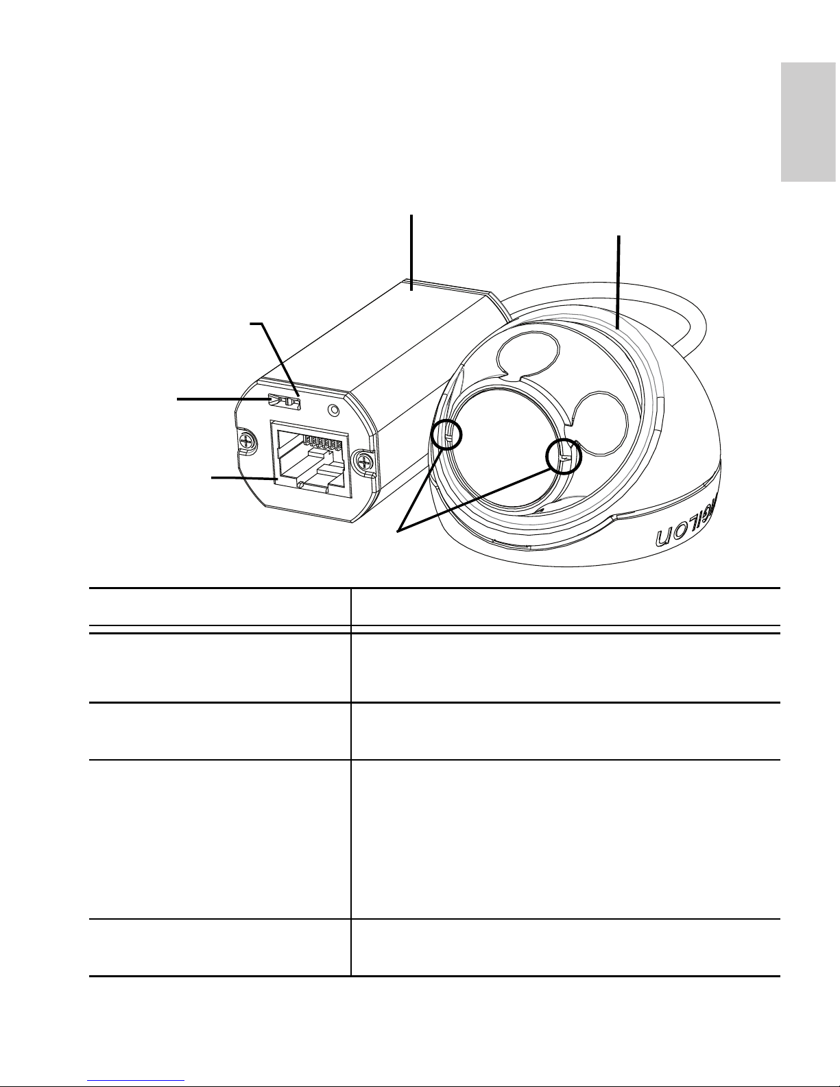
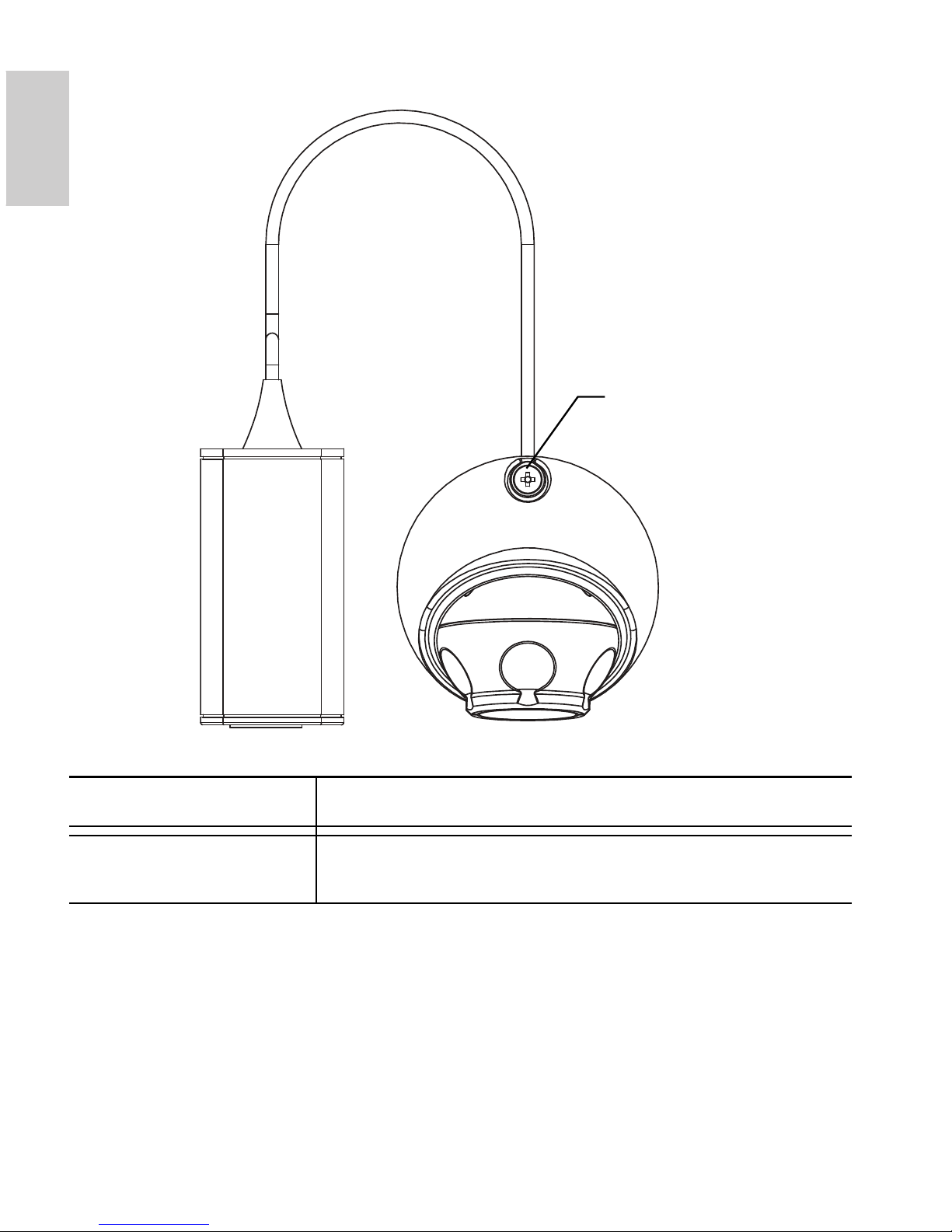
Front View
Feature Description
Connection Status LED Provides information about device operation.
See LED indicators for more information.
Link LED Indicates if there is an active connection in the
Ethernet port.
Ethernet Port Accepts power and Ethernet connection to the
network.
The camera can only be powered by Power
over Ethernet (PoE). Server communication
and image data transmission occurs over this
connection.
Horizon Markers Provides a reference point for aligning the
video image with the horizon line.
Ethernet Port
Connection Status
LED
Cable Assembly
HD Micro Dome
Camera
Link LED
Horizon Markers
Page 10
2
English
Top View
Feature Description
Tamper Proof Screw TORX tamper-resistant captive screw to fix the
dome cover to the base.
Tamper Proof Screw
Page 11

3
English
Installation
Required Tools and Materials
• 1 1/4” Hole Saw
• 3/16” drill bit for drywall or mineral fibre ceiling tile
installation
Camera Package Contents
Ensure the package contains the following:
• Avigilon HD Micro Dome Camera
• Mounting hardware
• Rubber boot
• T10 TORX tamper resistant key
• Mounting template sticker
Installation Steps
Complete the following procedures to install the dome camera.
1. Adding the Mounting Holes on page 4
2. Connecting PoE on page 5
3. Assigning an IP Address on page 6
4. Accessing the Live Video Stream on page 7
5. Mounting the HD Micro Dome Camera on page 7
6. Aiming the HD Micro Dome Camera on page 8
Page 12

4
English
Adding the Mounting Holes
The holes needed to mount the HD Micro Dome camera are very
close together so it is important to complete the following steps in
order to maintain the integrity of the mounting surface.
1. Make sure the arrow on the mounting template points in
the direction that the camera will face then attach the
template to the mounting surface.
2. Mark the centers of the mounting holes through the
mounting template and onto the mounting surface.
You only need to mark the larger hole if you plan to store
the cable assembly inside the wall.
3. Drill the two smaller holes (A).
• If mounting on drywall, use a 3/16” diameter drill bit
and install the supplied inserts.
• If mounting on wood, make a pilot hole for #4 wood
screws.
• If mounting on any other surface, drill a hole that is
appropriate for the chosen mounting surface and
mounting hardware. Do not use screws larger than
a #4 screw.
4. If you plan to store the cable assembly inside the wall, drill
the larger 31.75mm (1.25”) hole (B) with a hole saw.
NOTE: If the area behind the mounting surface is prone to water and
dust, make sure the provided rubber boot is used to protect the
camera’s PoE connection.
Page 13
5
English
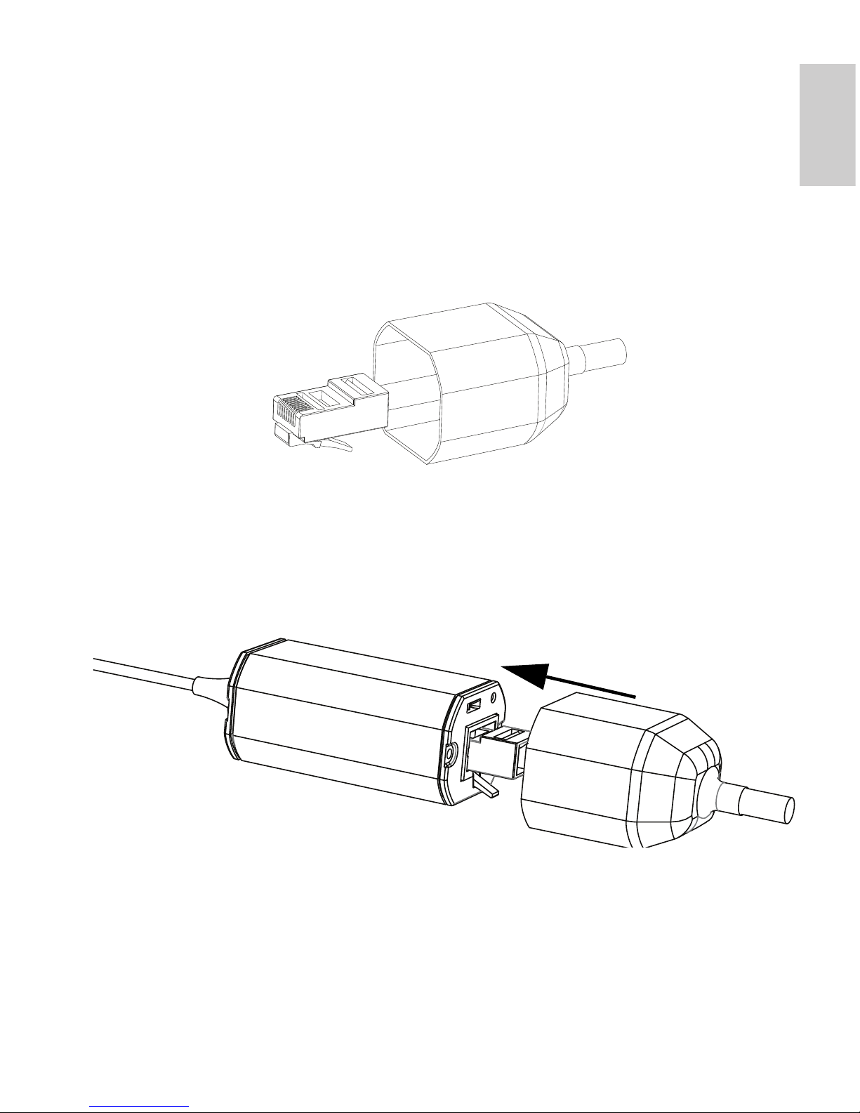
Connecting PoE
The HD Micro Dome camera can only be powered by Power over
Ethernet (PoE).
1. Pull the required Ethernet cable to the camera.
2. If you are installing the camera outdoors, slide the cable
through the supplied rubber boot.
3. Crimp the end of the cable with an Ethernet connector.
4. Connect the crimped cable to the Ethernet Port.
5. Check that the camera’s status LEDs indicate the correct
state. See LED Indicators on page 10 for more
information.
6. If you installed the rubber boot, slide the boot over the end
of the cable assembly.
7. Tuck the cable assembly away.
a. If you are storing the cable inside the wall, push the
cable assembly through the larger hole in the
mounting surface.
Page 14

6
English
b. If you are not, use pliers to pull off the tab covering
the back cable notch. Tuck the cable under the
notch when you mount the camera.
The camera is completely sealed, so the cable notch can
be placed in any direction as long as the camera is aimed
in the right direction.
Assigning an IP Address
The camera automatically obtains an IP address by default. Once
connected to a network, it attempts to locate and obtain an IP address
from a DHCP server. If this fails, Zero Configuration Networking
(Zeroconf) is used to choose an IP address. When the IP address is
set using Zeroconf, the IP address is in the 169.254.0.0/16 subnet.
The IP address settings can be changed using one of the following
methods:
• Avigilon Camera Installation Tool software application.
• Camera's web browser interface:
http://<camera IP address>/
• ARP/Ping method. For more information, see Setting the
IP Address through the ARP/Ping Method.
• Network Video Management software application (for
example, Avigilon Control Center).
Cable notch
Page 15
7
English
NOTE: The default camera username is admin and the default
password is admin.
Accessing the Live Video Stream
Live video stream can be viewed using one of the following methods:
• Avigilon Camera Installation Tool software application.
• Camera's web browser interface:
http://<camera IP address>/.
• Network Video Management software application (for
example, Avigilon Control Center).
NOTE: The default camera username is admin and the default
password is admin.
Mounting the HD Micro Dome Camera
1. Use the provided tamper resistant key to loosen the
tamper proof screw on the camera, then lift the camera
cover up from the back until it comes off the base.
When the cover is off, the camera will hang loose by the
cable.
2. Install the camera base to the mounting surface.
If you are storing the cable assembly inside the wall, make
sure the hole is completely covered by the camera.
Page 16

8
English
a. Move the camera away from the mounting holes.
b. Drive the supplied screws through the mounting
holes and into the mounting surface.
You may use other hardware that is appropriate to the
mounting surface.
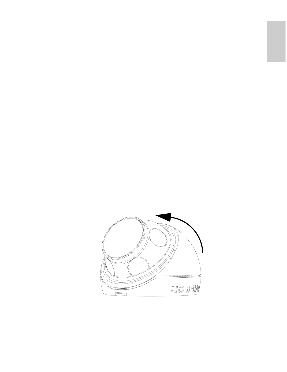
Aiming the HD Micro Dome Camera
1. After the camera has been mounted, place the camera
into the dome cover.
NOTE: Push the cable into the dome cover so that the cable does not
get caught between the cover and the base.
2. Hook the forward edge of the dome cover to the base and
loosely trap the camera.
Mounting screws
Hook
Page 17
9
English
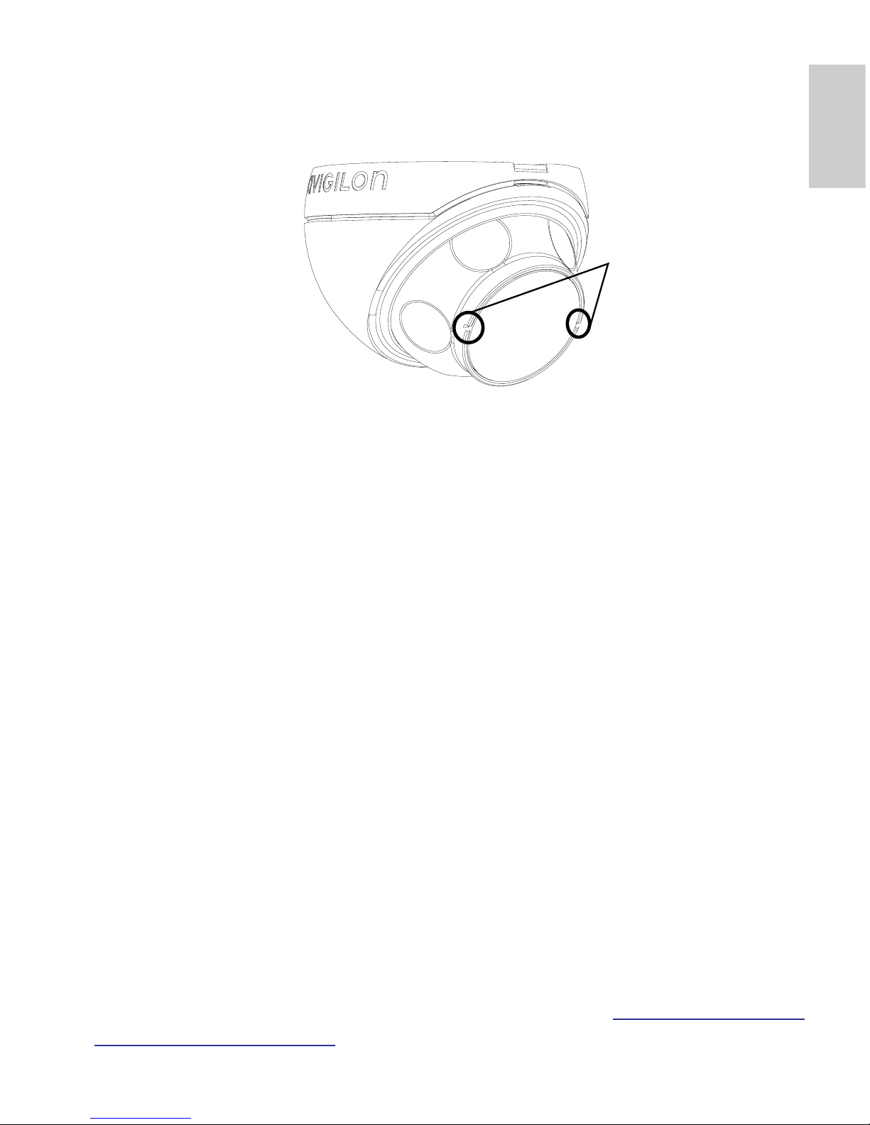
3. While the camera is trapped by one hand, use your other
hand to hold the dimples along the sides to move and aim
the camera. Make sure the camera lens is aligned with the
horizon.
Tip: If you have trouble aiming the camera, try any of the following:
• If the camera is stuck to the dome cover, lift the
dome cover slightly and push the camera into the
base to loosen the grip.
• If the camera won’t turn as far as you want, try
turning it in the opposite direction.
• If the video image is upside-down, you can digitally
flip the image in the network video management
software rather than re-aim the camera.
4. When the camera has been aimed, use the provided
tamper resistant key to tighten the cover to the base.
For More Information
Additional information about setting up and using the device is
available in the following guides:
• Avigilon Camera Installation Tool User Guide
• Avigilon Control Center Client User Guide
• Avigilon High Definition H.264 Web Interface User Guide
The manuals are available on the Avigilon website:
http://avigilon.com/
support-and-downloads.
Horizon markers
Page 18
10
English
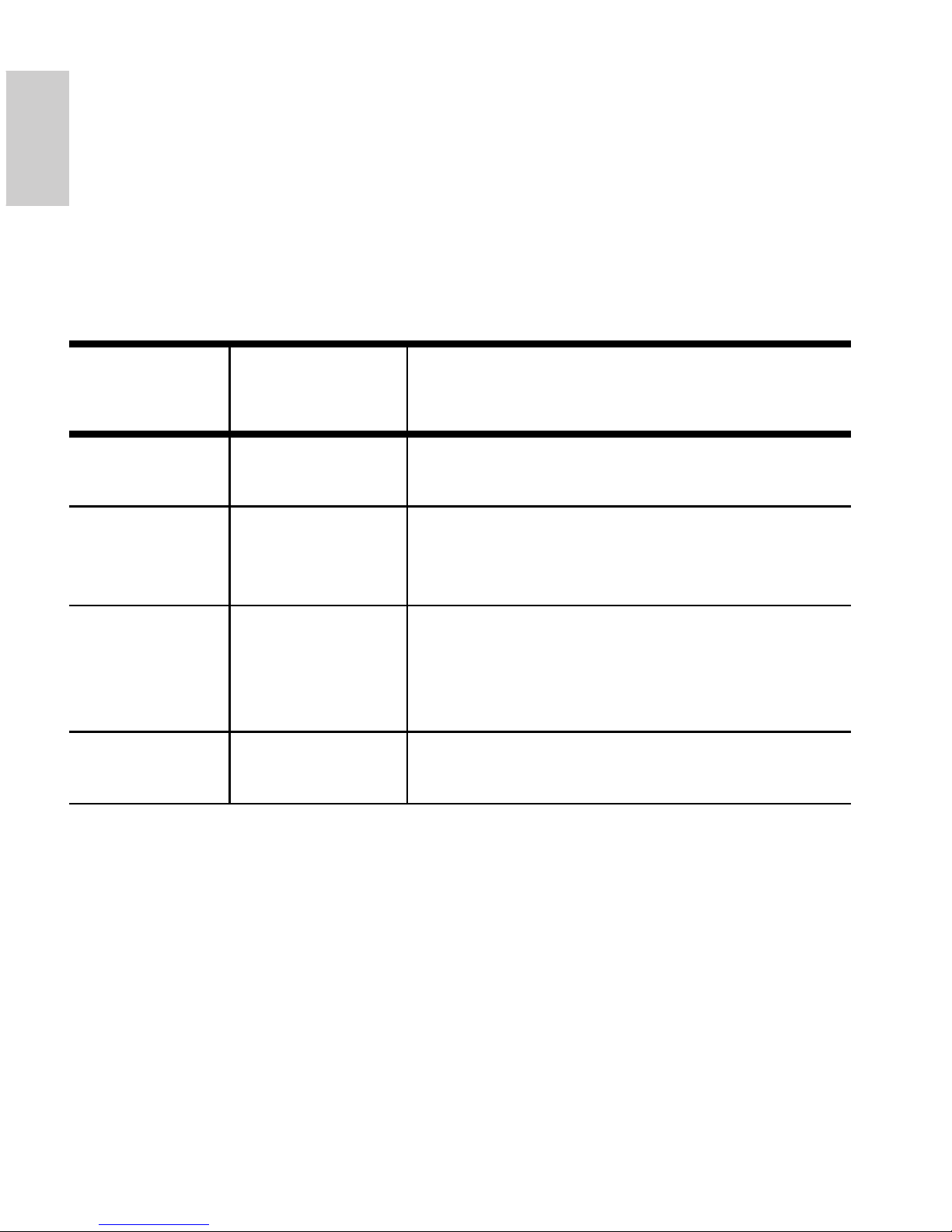
LED Indicators
Once the camera is connected to the network, the Connection Status
LED will display the camera’s progress in connecting to the Network
Video Management software.
The following table describes what the LEDs indicate:
Table:LED Indicators
Connection
State
Connection
Status LED
Description
Obtaining IP
Address
One short flash
every second
Attempting to obtain an IP address.
Discoverable Two short
flashes every
second
Obtained an IP address but is not
connected to the Network Video
Management software.
Upgrading
Firmware
Two short
flashes and
one long flash
every second
Updating the firmware.
Connected On Connected to the Network Video
Management software.
Page 19
11
English
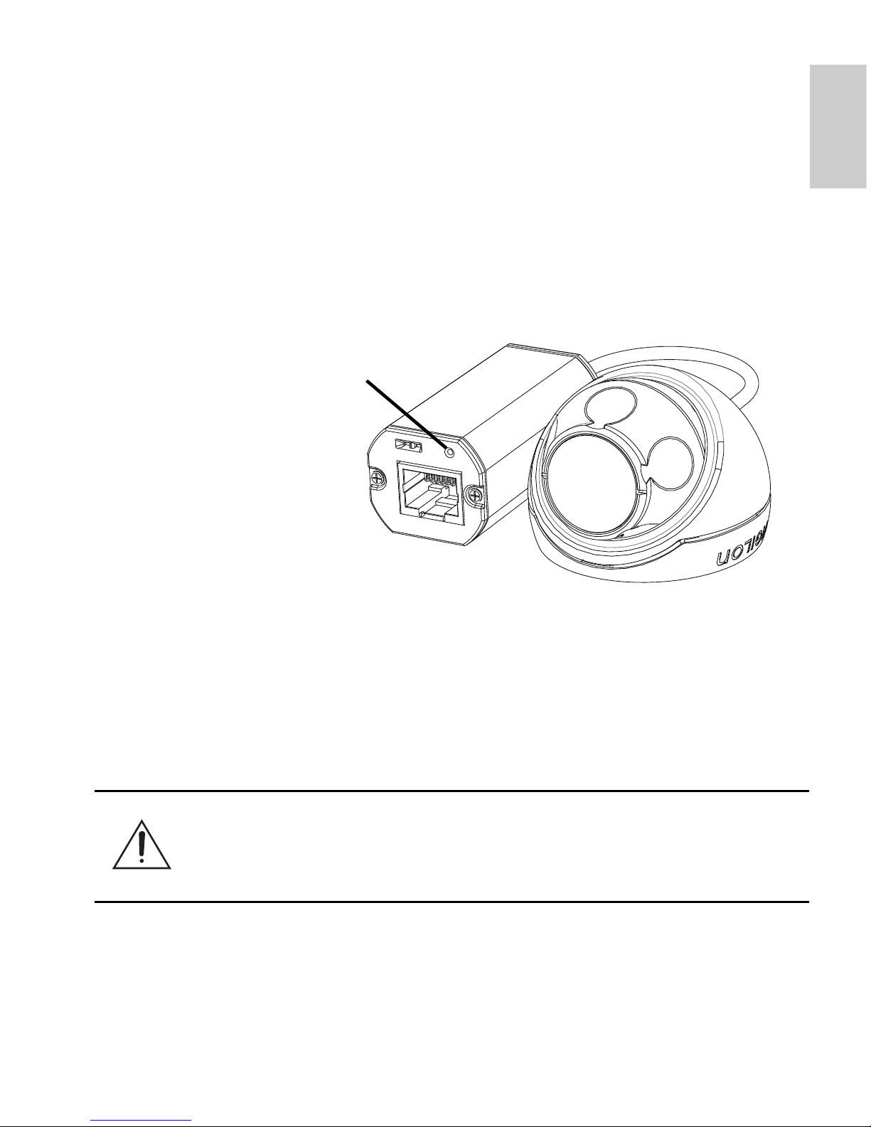
Reset to Factory Default
Settings
If the camera no longer functions as expected, you can choose to
restore the camera to its factory default settings.
Use the firmware revert button to reset the camera.
Figure: The firmware revert button on the cable assembly.
1. Disconnect power from the camera.
2. Using a straightened paperclip or similar tool, gently press
and hold the firmware revert button.
3. While continuing to hold the button, power the device.
Release the button after three seconds.
Caution — Do not apply excessive force. Inserting the tool
too far will damage the device.
Firmware Revert Button
Page 20

12
English
Setting the IP Address
Through the ARP/Ping Method
Complete the following steps to configure the camera to use a specific
IP address:
1. Locate and copy down the MAC Address (MAC) listed on
the Serial Number Tag for reference.
2. Open a Command Prompt window and enter the following
commands:
a. arp -s <New Camera IP Address> <Camera
MAC Address>
For example: arp -s 192.168.1.10 00-18-
85-12-45-78
b. ping -l 123 -t <New Camera IP Address>
For example: ping -l 123 -t 192.168.1.10
3. Reboot the camera.
4. Close the Command Prompt window when you see the
following message:
Reply from <New Camera IP Address>: ...
Page 21

13
English
Specifications
Camera
Lens 2.8mm, F2.0
Network
Network 100Base-TX
Cabling Type CAT5
Connector RJ-45
API ONVIF compliance version 1.02, 2.00, Profile S (www.onvif.org)
Security Password protection, HTTPS encryption, digest authentication, WS
authentication, user access log
Protocols IPv4, HTTP, HTTPS, SOAP, DNS, NTP, RTSP, RTCP, RTP, TCP, UDP,
IGMP, ICMP, DHCP, Zeroconf, ARP
Streaming Protocols RTP/UDP, RTP/UDP multicast, RTP/RTSP/TCP, RTP/RTSP/HTTP/
TCP,RTP/RTSP/HTTPS/TCP, HTTP
Mechanical
Dimensions ØxH 37.15 mm x 51.15 mm (1.48” x 2.01”)
Weight 34 g (1.19 oz)
+ 36 g (1.27 oz) for cable
Body Plastic
Housing Surface mount, tamper resistant
Finish Plastic, RAL 9003
Adjustment Range ±40° pan, ±40° tilt, 120° azimuth
Electrical
Power Consumption 4 W max.
Power Source PoE: IEEE802.3af Class 1 compliant
Environmental
Operating Temperature -10 °C to +50 °C (14 °F to 122 °F)
Storage Temperature -30 °C to +70 °C (-22 °F to 158 °F)
Certifications
Safety UL 60950 CE UVV
CSA 60950 ROHS C-Tick
CB Scheme WEEE
Environmental Meets IP66 Weather Rating
Electromagnetic Emissions FCC Part 15 Subpart B Class B IC ICES-003 Class B
EN 55022 Class B
Electromagnetic Immunity EN 55024 Class B EN 61000-4-2
EN 61000-4-3 EN 61000-4-4
EN 61000-4-5 EN 61000-4-6
EN 61000-4-11
Page 22

14
English
Limited Warranty & Technical Support
Avigilon warrants to the original consumer purchaser, that this product will be
free of defects in material and workmanship for a period of 3 years from date of
purchase.
The manufacturer’s liability hereunder is limited to replacement of the product,
repair of the product or replacement of the product with repaired product at the
discretion of the manufacturer. This warranty is void if the product has been
damaged by accident, unreasonable use, neglect, tampering or other causes
not arising from defects in material or workmanship. This warranty extends to
the original consumer purchaser of the product only.
AVIGILON DISCLAIMS ALL OTHER WARRANTIES EXPRESSED OR
IMPLIED INCLUDING, WITHOUT LIMITATION, ANY IMPLIED WARRANTIES
OF MERCHANTABILITY OR FITNESS FOR A PARTICULAR PURPOSE,
EXCEPT TO THE EXTENT THAT ANY WARRANTIES IMPLIED BY LAW
CANNOT BE VALIDLY WAIVED.
No oral or written information, advice or representation provided by Avigilon, its
distributors, dealers, agents or employees shall create another warranty or
modify this warranty. This warranty states Avigilon’s entire liability and your
exclusive remedy against Avigilon for any failure of this product to operate
properly.
In no event shall Avigilon be liable for any indirect, incidental, special,
consequential, exemplary, or punitive damages whatsoever (including but not
limited to, damages for loss of profits or confidential or other information, for
business interruption, for personal injury, for loss of privacy, for failure to meet
any duty including of good faith or of reasonable care, for negligence, and for
any other pecuniary or other loss whatsoever) arising from the use of or inability
to use the product, even if advised of the possibility of such damages. Since
some jurisdictions do not allow the above limitation of liability, such limitation
may not apply to you.
This Limited Warranty gives you specific legal rights and you may also have
other rights which vary from jurisdiction to jurisdiction.
Warranty service and technical support can be obtained by
contacting Avigilon Technical Support by phone at
1.888.281.5182 or via email at support@Avigilon.com.
Page 23
Guide d'installation
Modèles de caméra Micro Dome IP H.264
haute définition Avigilon :
1.0-H3M-DO1 et 2.0-H3M-DO1
Page 24

Page 25
i
Français
Informations de sécurité
importantes
Ce manuel fournit des informations d'installation et d'exploitation, ainsi que
des précautions d'utilisation pour la caméra dôme. Une installation
incorrecte peut entraîner une défaillance imprévue. Avant d'installer cet
équipement, lisez attentivement ce manuel. Veuillez remettre ce manuel au
propriétaire de l'équipement pour une utilisation ultérieure.
• L'installation doit être effectuée par un personnel qualifié
uniquement et doit être en conformité avec tous les codes
locaux.
• Ce produit doit être alimenté par une alimentation répertoriée
UL, PSE, PoE (Power over Ethernet) d'une tension nominale
de 48 VCC et d'une puissance minimale de 4 W.
Le symbole d'avertissement indique la présence de
tensions dangereuses, à l'intérieur et à l'extérieur du boîtier
du produit, susceptibles de générer un risque de choc
électrique, de blessure grave, voire de décès, si des
précautions appropriées ne sont pas prises.
Le symbole Attention alerte l'utilisateur sur la présence de
dangers susceptibles d'infliger aux personnels des
blessures mineures à modérées, d'endommager des biens
ou le produit lui-même si des précautions appropriées ne
sont pas prises.
Warning — Le non-respect des instructions suivantes est
susceptible d'entraîner des blessures graves voire le décès.
Caution — Le non-respect des instructions suivantes est
susceptible d'entraîner des blessures et d'endommager la
caméra dôme.
Page 26

ii
Français
• N'effectuez aucune installation à proximité de sources de
chaleur telles que radiateurs, bouches de chaleur ou poêles.
• Ne soumettez pas les câbles à des tensions, des charges ou
des pincements excessifs.
• N'ouvrez pas l'équipement, ne le démontez pas. Il ne contient
aucune pièce sur laquelle l'utilisateur peut intervenir.
• Pour toute intervention, contactez un personnel qualifié.
Une intervention peut se révéler nécessaire lorsque
l'équipement est endommagé (par exemple, par le
renversement d'un liquide ou la chute d'un objet), lorsqu'il a été
exposé à la pluie ou à l'humidité (présence de moisissure),
lorsqu'il ne fonctionne pas normalement ou lorsqu'il a chuté.
• N'utilisez pas de détergents puissants ou abrasifs lorsque vous
nettoyez le corps de l'équipement.
• Utilisez uniquement les accessoires recommandés par
Avigilon.
Page 27
iii
Français
Avis concernant la réglementation
Cet équipement est conforme à section 15 des règles FCC. Son
exploitation est sujettes aux deux conditions suivantes : (1) Cet équipement
ne risque pas de générer d'interférences nuisibles et (2) cet équipement
doit accepter toute interférence reçue, y compris celles susceptibles
d'induire un fonctionnement indésirable.
Cet équipement numérique de Classe B est conforme à la norme
canadienne ICES-003.
Notice FCC
Cet équipement a été testé et déclaré conforme aux limitations relatives à
un appareil numérique de classe B, en vertu de la Sous-section B de la
Section 15 des règles de la FCC. Ces limitations visent à assurer une
protection raisonnable contre les interférences dans le cadre d'une
exploitation de l'équipement dans un environnement commercial.
L'exploitation de cet équipement dans une zone résidentielle est
susceptible de générer des interférences nuisibles, auquel cas l'utilisateur
sera tenu de prendre toute mesure nécessaire pour remédier à ces
interférences.
Tout changement ou modification apporté à cet équipement non
expressément approuvé par Avigilon Corporation ou des tiers autorisés par
Avigilon Corporation pourrait annuler l'autorisation accordée à l'utilisateur
d'utiliser cet équipement.
Informations sur la mise au rebut et le recyclage
Lorsque ce produit aura atteint la fin de sa vie utile, veuillez le mettre au
rebut conformément aux directives et à la législation locales sur
l'environnement.
Union européenne :
Ce symbole signifie que, conformément aux lois et aux
réglementations locales, votre produit doit être mis au rebut hors
déchets ménagers. Lorsque ce produit aura atteint la fin de sa vie
utile, portez-le à un point de collecte désigné par les autorités
locales. Certains points de collecte acceptent gratuitement les
produits. La collecte et le recyclage séparés de votre produit au
moment de la mise au rebut contribuent à conserver les
ressources naturelles et garantissent que le produit est recyclé de
sorte à protéger la santé humaine et l'environnement.
Page 28

iv
Français
Autres notices
Notice sur la compilation et la publication
Ce manuel a été compilé et publié en couvrant les spécifications et
descriptions de produit les plus récentes. Le contenu de ce manuel et les
spécifications de ce produit sont sujets à modifications sans avis préalable.
Avigilon se réserve le droit d'apporter des modifications sans avis préalable
aux spécifications et informations présentées dans le présent manuel.
Avigilon ne saurait être tenu responsable de tout dommage (notamment
accessoire) causé par le fait de se fier aux informations présentées,
notamment mais sans s'y limiter, en termes d'erreurs typographiques et
d'autres erreurs liées à la publication.
Notice de propriété intellectuelle
Aucun licence n'est accordée par implication ou autre action dans le cadre
de toute conception industrielle, de droits de conception industriels, de
brevet et droits de brevet, ou de droits de reproduction (copyrights)
d'Avigilon Corporation ou de ses concédants de licence. Les marques
commerciales et les marques déposées sont la propriété de leurs
détenteurs respectifs.
Page 29

Français
Tables des matières
Présentation générale. . . . . . . . . . . . . . . . . . . . 1
Vue avant . . . . . . . . . . . . . . . . . . . . . . . . . . . . . . . . 1
Vue du dessus . . . . . . . . . . . . . . . . . . . . . . . . . . . . . 2
Installation . . . . . . . . . . . . . . . . . . . . . . . . . . . . 3
Outils et matériel requis . . . . . . . . . . . . . . . . . . . . . . 3
Contenu du conditionnement de la caméra . . . . . . . 3
Étapes d'installation . . . . . . . . . . . . . . . . . . . . . . . . . 3
Ajout de trous de fixation . . . . . . . . . . . . . . . 4
Raccordement PoE . . . . . . . . . . . . . . . . . . . 5
Affectation d'une adresse IP . . . . . . . . . . . . . 6
Accès au flux vidéo en direct . . . . . . . . . . . . 7
Fixation de la caméra HD Micro Dome . . . . . 7
Visée de la caméra HD Micro Dome . . . . . . 8
Pour plus d'informations... . . . . . . . . . . . . . 10
Indications des LED . . . . . . . . . . . . . . . . . . . . 11
Réinitialiser les paramètres d'usine
par défaut . . . . . . . . . . . . . . . . . . . . . . . . . . . . 12
Configuration de l'adresse IP par le biais
de la méthode ARP/Ping . . . . . . . . . . . . . . . . 13
Spécifications . . . . . . . . . . . . . . . . . . . . . . . . . 14
Garantie limitée et assistance technique . . . 15
Page 30

Français
Page 31

1
Français
Présentation générale
Vue avant
Caractéristique Description
LED d'état de
connexion
Fournit des informations sur le fonctionnement de
l'équipement. Reportez-vous à la section relative
aux indications des LED pour plus d'informations.
LED de liaison Indique si une connexion est active sur le port
Ethernet.
Port Ethernet Accepte une alimentation et une connexion
Ethernet au réseau.
La caméra ne peut s'alimenter que par la
technologie PoE (Power over Ethernet). La
transmission des données d'images et de la
communication avec le serveur s'effectue par
cette connexion.
Marqueur d'horizon Fournit un point de référence pour l'alignement de
l'image vidéo sur la ligne d'horizon.
Port Ethernet
LED d'état de
c
onnexion
Faisceau de câblage
Caméra HD
Micro Dome
LED de
liaison
Marqueur d'horizon
Page 32

2
Français
Vue du dessus
Caractéristique Description
Vis résistante aux
effractions
Vis imperdable TORX résistante aux
effractions pour fixer le dôme de protection à
la base.
Vis résistante aux
effractions
Page 33

3
Français
Installation
Outils et matériel requis
• Emporte-pièce 31,75 mm (1 1/4")
• Mèche de perçage 4,76 mm (3/16") pour installation sur
cloison sèche ou sur carreaux de plafond en fibre minérale
Contenu du conditionnement de la caméra
Assurez-vous que le conditionnement contient les éléments suivants :
• Caméra HD Micro Dome Avigilon
• Matériel de fixation
• Manchon en caoutchouc
• Clé TORX T10 résistante aux effractions
• Auto-collant de gabarit de montage
Étapes d'installation
Effectuez les procédures suivantes pour installer la caméra dôme.
1. Ajout de trous de fixation à la page 4
2. Raccordement PoE à la page 5
3. Affectation d'une adresse IP à la page 6
4. Accès au flux vidéo en direct à la page 7
5. Fixation de la caméra HD Micro Dome à la page 7
6. Visée de la caméra HD Micro Dome à la page 8
Page 34

4
Français
Ajout de trous de fixation
Les trous nécessaires au montage de la caméra HD Micro Dome sont
très rapprochés. Il est donc important de procéder selon les étapes
qui suivent afin de préserver l'intégrité de la surface de fixation.
1. Veillez à ce que la flèche placée sur le gabarit de montage
pointe dans la direction dans laquelle la caméra sera
orientée, puis fixez le gabarit sur la surface de fixation.
2. Marquez les centres des trous de fixation à travers le
gabarit de montage, sur la surface de fixation.
Si vous envisagez de stocker le faisceau de câblage à
l'intérieur du mur, seul le marquage du plus grand trou est
nécessaire.
3. Percez les deux plus petits trous (A).
• En cas de fixation sur cloison sèche, utilisez une mèche
de perçage d'un diamètre de 4,76 mm (3/16") et
installez les connexions fournies.
• En cas de montage sur du bois, faites un trou de
guidage pour les vis à bois n°4.
• En cas de montage sur toute autre surface, percez le
trou adapté à la surface choisie et au matériel de
fixation. N'utilisez pas de vis plus grandes que la n°4.
4. Si vous envisagez de stocker le faisceau de câblage à
l'intérieur du mur, percez le plus grand trou (B ; 31,75 mm)
à la scie cloche.
REMARQUE : Si la zone qui se trouve derrière la surface de montage
est exposée à l'eau et à la poussière, veillez à bien
utiliser le manchon en caoutchouc fourni pour protéger
la connexion PoE de la caméra.
Page 35

5
Français
Raccordement PoE
La caméra HD Micro Dome ne peut s'alimenter que par la technologie
PoE (Power over Ethernet).
1. Tirez le câble Ethernet requis vers la caméra.
2. Si vous installez la caméra en extérieur, faites glisser le
câble à travers le manchon en caoutchouc fourni.
3. Sertissez l'extrémité du câble avec un connecteur
Ethernet.
4. Raccordez le câble serti au port Ethernet.
5. Vérifiez que la LED d'état de la caméra indique bien un
état correct. Reportez-vous à la section relative aux
Indications des LED à la page 11 pour plus d'informations.
6. Si vous avez installé le manchon en caoutchouc, faites-le
glisser sur l'extrémité du faisceau de câblage.
7. Rentrez l'excédent de faisceau de câblage.
a. Si vous stockez le câble à l'intérieur du mur,
poussez le faisceau à travers le plus grand trou de
la surface de fixation.
Page 36

6
Français
b. Dans la négative, utilisez une pince pour retirer le
taquet qui recouvre l'encoche à l'arrière du câble.
Rentrez le câble sous l'encoche lorsque vous fixez
la caméra.
La caméra est totalement scellée. Ainsi lorsque la visée de
la caméra est bien orientée, l'encoche du câble peut être
orientée dans n'importe quelle direction.
Affectation d'une adresse IP
La caméra obtient automatiquement une adresse IP par défaut. Une
fois connectée à un réseau, l'appareil tente de localiser un serveur
DHCP et d'obtenir une adresse IP auprès de ce dernier. En cas
d'échec, la méthode Zeroconf (Zero Configuration Networking) est
utilisée pour sélectionner une adresse IP. Si l'adresse IP est définie au
moyen de Zeroconf, son sous-réseau sera 169.254.0.0/16.
Les paramètres d'adresse IP peuvent être modifiés au moyen d'une
des méthodes suivantes :
• Logiciel de l'utilitaire d'installation des caméras Avigilon.
• Interface du navigateur Web de la caméra :
http://<adresse IP de la caméra>/.
• Méthode ARP/Ping. Pour plus d'informations, consultez la
section Configuration de l'adresse IP par le biais de la
méthode ARP/Ping.
L'encoche du câble
Page 37

7
Français
• Application logicielle NVMS (Network Video Management
Software ; par exemple, Avigilon Control Center).
REMARQUE : Le nom d'utilisateur par défaut de la caméra est admin
et le mot de passe par défaut admin.
Accès au flux vidéo en direct
Le flux vidéo en direct peut être consulté au moyen d'une des
méthodes suivantes :
• Logiciel de l'utilitaire d'installation des caméras Avigilon.
• Interface du navigateur Web de la caméra :
http://<adresse IP de la caméra>/.
• Application logicielle NVMS (Network Video Management
Software ; par exemple, Avigilon Control Center).
REMARQUE : Le nom d'utilisateur par défaut de la caméra est admin
et le mot de passe par défaut admin.
Fixation de la caméra HD Micro Dome
1. Utilisez la clé résistante aux effractions fournie pour
desserrer la vis du même type sur la caméra, puis
soulevez le capot de la caméra depuis l'arrière jusqu'à ce
qu'il se sépare de la base.
Une fois le capot déposé, la caméra pend au bout du
câble.
2. Installez la base de la caméra sur la surface de fixation.
Si vous stockez le faisceau de câble à l'intérieur du mur,
veillez à ce que le trou soit complètement couvert par la
caméra.
Page 38

8
Français
a. Éloignez la caméra des trous de fixation.
b. Engagez les vis fournies dans les trous de fixation
et dans la surface de fixation.
Vous pouvez utiliser d'autres éléments de montage
adaptés à la surface de fixation.
Visée de la caméra HD Micro Dome
1. Une fois la caméra fixée, placez-là dans le dôme de
protection.
REMARQUE : Poussez le câble dans le dôme de protection de sorte
qu'il ne reste pas coincé entre le capot et la base.
2. Accrochez le bord avant du dôme de protection à la base
et enfermez la caméra sans forcer.
Vis de fixation
Crochet
Page 39

9
Français
3. Avec la caméra bloquée dans une main, de l'autre main,
maintenez les crans le long des côtés afin de déplacer la
caméra et de régler sa visée. Assurez-vous que l'objectif
de la caméra est bien aligné sur l'horizon.
Conseil : Si vous avez des difficultés à régler la visée de la caméra,
essayez une des techniques suivantes :
• Si la caméra est collée au dôme de protection, levez ce
dernier légèrement et poussez la caméra dans la base
pour alléger le blocage.
• Si la caméra ne tourne pas aussi loin que vous le
souhaitez, essayez de la tourner dans le sens opposé.
• Si l'image vidéo est à l'envers, vous pouvez l'inverser
numériquement au niveau du logiciel NVMS, plutôt que
de changer la visée de la caméra.
4. Une fois la visée de la caméra réglée, utilisez la clé
résistante aux effractions fournie pour serrer le capot sur
la base.
Marqueur d'horizon
Page 40

10
Français
Pour plus d'informations...
Les guides suivants présentent des informations supplémentaires sur
la configuration et l'utilisation de l'appareil :
• Guide de l'utilitaire d'installation des caméras Avigilon
• Guide de l'utilisateur d'Avigilon Control Center Client
• Guide de l'utilisateur de l'interface Web Avigilon haute
définition H.264
Les manuels sont disponibles sur le site Web d'Avigilon :
http://avigilon.com/support-and-downloads.
Page 41

11
Français
Indications des LED
Une fois la caméra raccordée au réseau, des diodes, ou LED, d'état
de connexion affichent la progression de la connexion de la caméra
au logiciel NVMS (Network Video Management Software).
Le tableau suivant décrire les indications des LED :
Tableau : Indications des LED
État de la
connexion
LED d'état de
connexion
Description
Obtention d'une
adresse IP
Un clignotement bref
à chaque seconde
Tentative d'obtention d'une
adresse IP
Détectable Deux clignotements
brefs à chaque
seconde
Une adresse IP a été
obtenue mais elle n'est pas
connectée au logiciel NVMS
(Network Video Management
Software).
Mise à niveau
du microcode
Deux clignotements
brefs et un long à
chaque seconde
Mise à niveau du microcode
Connecté Allumé Connectée au logiciel NVMS.
Page 42

12
Français
Réinitialiser les paramètres
d'usine par défaut
Si la caméra ne fonctionne plus comme attendu, vous pouvez opter
pour la restauration de ses paramètres d'usine par défaut.
Utilisez le bouton de réinitialisation du microcode pour réinitialiser la
caméra.
Figure :
Bouton de réinitialisation du microcode sur le faisceau de câble.
1. Débranchez l'alimentation de la caméra.
2. Avec un trombone redressé ou un outil pointu similaire,
appuyez légèrement sur le bouton de réinitialisation du
microcode et maintenez-le enfoncé.
3. Tout en maintenant le bouton enfoncé, mettez l'appareil
sous tension. Relâchez le bouton au bout de trois
secondes.
Attention — N'appliquez pas une force excessive. Une
insertion trop profonde de l'outil endommagerait l'appareil.
Bouton de réinitialisation
du microcode
Page 43

13
Français
Configuration de l'adresse IP par
le biais de la méthode ARP/Ping
Procédez selon les étapes suivantes pour configurer la caméra et
utiliser une adresse IP spécifique :
1. Identifiez et copiez l'adresse MAC répertoriée sur
l'étiquette de numéro de série pour référence.
2. Ouvrez une fenêtre d'invite de commande, puis saisissez
les commandes suivantes :
a. arp -s <Nouvelle adresse IP de la
caméra> <Adresse MAC de la caméra>
Par exemple : arp -s 192.168.1.10 00-18-
85-12-45-78
b. ping -l 123 -t <Nouvelle adresse IP de
la caméra>
Par exemple : ping -l 123 -t 192.168.1.10
3. Réinitialisez la caméra.
4. Fermez la fenêtre d'invite de commande lorsque le
message suivant s'affiche :
Reply from <Nouvelle adresse IP de la
caméra> : ...
Page 44

14
Français
Spécifications
Caméra
Objectifs 2,8 mm, F2.0
Réseau
Réseau 100Base-TX
Type de câblage CAT5
Connecteur RJ-45
API Compatibilité ONVIF version 1.02, 2.00, Profile S (www.onvif.org)
Sécurité Protection par mot de passe, cryptage HTTPS, authentification
Digest, authentification WS, journal d'accès des utilisateurs
Protocoles IPv4, HTTP, HTTPS, SOAP, DNS, NTP, RTSP, RTCP, RTP, TCP, UDP,
IGMP, ICMP, DHCP, Zeroconf et ARP
Protocoles de flux RTP/UDP, RTP/UDP multicast, RTP/RTSP/TCP, RTP/RTSP/HTTP/
TCP,RTP/RTSP/HTTPS/TCP, HTTP
Mécanique
Cotes Ø x H 37,15 mm x 51,15 mm (1,48” x 2,01”)
Poids 34 g (1,19 oz)
+ 36 g (1,27 oz) pour le câble
Corps Plastique
Boîtier Montage sur surface, résistant aux effractions
Finition Plastique, RAL 9003
Plage de réglage Panoramique à ± 40°, inclinaison à ± 40°, azimut à 120°
Électrique
Consommation électrique 4 W max.
Source d'alimentation PoE : IEEE802.3af, compatible Classe 1
Environnemental
Température d'exploitation -10 à +50 °C (14 à 50,00 °F)
Température de stockage -30 à +70 °C (-22 à +158 °F)
Certifications
Sûreté UL 60950 CE CSA 60950 UVV
ROHS CB Scheme WEEE C-Tick
Enironnemental Conforme à la classification environnementale IP66
Émissions
électromagnétiques
FCC, section 15, sous-section B, classe B
IC ICES-003 Classe B EN 55022 Classe B
Immunité
électromagnétique
EN 55024 Classe B EN 61000-4-2 EN 61000-4-3
EN 61000-4-4 EN 61000-4-5 EN 61000-4-6
EN 61000-4-11
Page 45

15
Français
Garantie limitée et assistance technique
Avigilon garantit à l'acheteur consommateur d'origine que ce produit est exempt de
défectuosités liées au matériel ou à la main-d'oeuvre pour une période de 3 années à
compter de la date d'achat.
La responsabilité du fabricant explicitée ci-dessous se limite au remplacement ou la
réparation du produit, voire au remplacement du produit par un produit réparé, et ce à
la discrétion du fabricant. Cette garantie s'annule dès lors que le produit est
endommagé par accident, utilisation irraisonnée, négligence, modification ou toute
autre cause non liée à des défectuosités relatives au matériel ou à la main-d'oeuvre.
Cette garantit couvre uniquement l'acheteur consommateur d'origine du produit.
AVIGILON REJETTE TOUTE AUTRE GARANTIE, EXPRESSE OU TACITE,
NOTAMMENT MAIS SANS S'Y LIMITER, TOUTE GARANTIE TACITE DE QUALITÉ
MARCHANDE OU D'ADÉQUATION À UN OBJECTIF PARTICULIER, SAUF DANS
LES CAS DE GARANTIE TACITE PAR FORCE DE LOI NE POUVANT ÊTRE
ANNULÉE DE MANIÈRE VIABLE.
Aucun conseil, information ou représentation, de nature orale ou écrite, fourni par
Avigilon, ses distributeurs, revendeurs, agents ou employés, ne saurait induire une
autre garantie ou modifier la présente garantie. La présente garantie spécifie l'entière
responsabilité d'Avigilon ainsi que votre recours exclusif auprès d'Avigilon pour toute
défaillance de ce produit dans le cadre d'une exploitation appropriée.
En aucun cas, Avigilon ne saurait être tenu responsable de tout dommage indirect,
accessoire, particulier, consécutif, exemplaire ou punitif de quelque nature que ce soit
(notamment mais sans s'y limiter, la perte de profits et d'informations, notamment
confidentielles, l'interruption d'activité, la blessure, la perte de confidentialité, la nonsatisfaction d'un devoir notamment la bonne foi ou les mesures raisonnables, la
négligence, ainsi que toute autre perte notamment d'ordre pécuniaire) induit par
l'utilisation du produit ou l'incapacité à utiliser le produit, même en cas d'avertissement
préalable quant à la possibilité d'un tel dommage. Sachant que certaines juridictions
n'autorisent pas la décharge de responsabilité ci-dessus, cette décharge peut ne pas
s'appliquer à votre cas.
La présente garantie limitée vous confère des droits légaux spécifiques. Vous pouvez
également disposer d'autres droits qui varient d'une juridiction à une autre.
Le service de garantie et l'assistance technique peuvent s'obtenir en
contactant le support technique Avigilon, par téléphone 1.888.281.5182 ou
par courrier électronique à l'adresse support@avigilon.com.
Page 46

Guía de instalación
Microcámara domo IP H.264 de alta
definición de Avigilon, modelos:
1.0-H3M-DO1 y 2.0-H3M-DO1
Page 47

Page 48

i
Español
Información importante sobre
la seguridad
Este manual proporciona información sobre la instalación y
funcionamiento de la cámara domo, así como precauciones a tener en
cuenta durante su uso. Una instalación incorrecta podría provocar un fallo
inesperado. Antes de instalar este equipo, lea atentamente este manual.
Proporcione este manual al propietario del equipo para usos futuros.
• La instalación solo debe efectuarla personal cualificado y
debe cumplir todas las normas locales.
• Este producto está pensado para recibir alimentación
eléctrica por Ethernet (PoE), con aprobación UL, potencia
nominal 48 VCC y 4 W mínimo.
• No instale el dispositivo cerca de fuentes de calor como
radiadores, rejillas de aire caliente, estufas, etc.
• No someta los cables a demasiada tensión, cargas
pesadas o pinzamientos.
El símbolo de advertencia indica la presencia de un voltaje
peligroso dentro y fuera de la carcasa del producto que puede
constituir un riesgo de descarga eléctrica, lesiones graves o la
muerte de personas si no se siguen las precauciones adecuadas.
El símbolo de precaución pone en alerta al usuario ante la
presencia de peligros que pueden provocar lesiones menores o
moderadas a personas, daños a la propiedad o daños al
producto si no se siguen las precauciones adecuadas.
Advertencia: Si no se tienen en cuenta las siguientes
instrucciones, pueden producirse lesiones graves o incluso
la muerte.
Precaución: Si no se tienen en cuenta las siguientes
instrucciones, pueden producirse lesiones o daños en la
cámara domo.
Page 49

ii
Español
• No abra ni desmonte el dispositivo. No hay ninguna pieza
que pueda reparar el usuario.
• Derive todas las reparaciones al personal cualificado.
Las reparaciones deben llevarse a cabo cuando el
dispositivo ha resultado dañado (como por ejemplo,
debido a un líquido que se ha derramado u objetos que
han caído), se ha expuesto a la lluvia o humedad, no
funciona correctamente o se ha caído.
• No utilice detergentes fuertes o abrasivos para limpiar el
cuerpo del dispositivo.
• Utilice únicamente accesorios recomendados por Avigilon.
Page 50

iii
Español
Avisos Regulatorios
Este dispositivo cumple con la Sección 15 de la Reglamentación FCC.
El funcionamiento está sujeto a las dos condiciones siguientes: (1)
Este dispositivo no ha de causar interferencias indeseadas, y (2) este
dispositivo debe aceptar cualquier interferencia recibida, incluyendo
interferencias que puedan causar un funcionamiento no deseado.
Este aparato digital de Clase B cumple con la normativa canadiense
ICES-003.
Aviso de la FCC
Este equipo ha sido probado y cumple con los límites establecidos
para dispositivos informáticos de Clase B, con arreglo a la Subsección
B de la Sección 15 de la Reglamentación FCC, diseñados para
proporcionar una protección razonable contra estas interferencias
cuando se utiliza en un entorno comercial. La utilización de este
equipo en una zona residencial probablemente ocasionará
interferencias, en cuyo caso el usuario deberá tomar las medidas
oportunas para corregir la interferencia a su propio coste.
Los cambios o modificaciones efectuados en este equipo no
aprobados expresamente por Avigilon Corporation o las partes
autorizadas por Avigilon Corporation podrían anular la capacidad del
usuario para utilizar el equipo.
Información sobre la eliminación de residuos y el reciclaje
Cuando este producto haya llegado al final de su vida útil, deshágase
de él de acuerdo con la legislación y normativa locales en materia de
medio ambiente.
Comunidad Europea:
Este símbolo significa que según la legislación y normativa locales su
producto debe eliminarse por separado de los residuos domésticos.
Cuando el producto llegue al final de su vida útil, llévelo a un punto de
recogida designado por las autoridades locales. Algunos puntos de
recogida aceptan productos de forma gratuita. La recogida y reciclaje
por separado del producto en el momento de su eliminación ayudará a
conservar los recursos naturales y garantizar que se recicla
respetando la salud y el medio ambiente.
Page 51

iv
Español
Otros avisos
Aviso de compilación y publicación
Este manual se ha compilado y publicado contemplando las
descripciones y especificaciones del producto más recientes. El
contenido de este manual y las especificaciones de este producto
están sujetos a cambios sin previo aviso. Avigilon se reserva el
derecho de efectuar cambios sin previo aviso en las especificaciones
y materiales contenidos aquí y no se hará responsable de ningún
daño (incluidos los resultantes) causados por depender de los
materiales presentados, incluidos a título enunciativo pero no
limitativo los errores tipográficos y otros errores relativos a la
publicación.
Aviso sobre la propiedad intelectual
No se concederá ninguna licencia por implicación o cualquier otra
circunstancia bajo ningún diseño industrial, derechos de diseño
industrial, patente, derechos de patente o copyrights de Avigilon
Corporation o sus licenciantes. Todas las marcas comerciales y
marcas comerciales registradas son propiedad de sus respectivos
propietarios.
Page 52

Español
Tabla de Contenidos
Visión general . . . . . . . . . . . . . . . . . . . . . . . . . . .1
Vista frontal . . . . . . . . . . . . . . . . . . . . . . . . . . . . . . . 1
Vista superior . . . . . . . . . . . . . . . . . . . . . . . . . . . . . . 2
Instalación . . . . . . . . . . . . . . . . . . . . . . . . . . . . . .3
Herramientas y materiales necesarios . . . . . . . . . . 3
Contenido del paquete de la cámara . . . . . . . . . . . . 3
Pasos para la instalación . . . . . . . . . . . . . . . . . . . . . 3
Adición de orificios de montaje . . . . . . . . . . . 4
Conexión de PoE . . . . . . . . . . . . . . . . . . . . . 5
Asignación de una dirección IP . . . . . . . . . . 6
Acceso al flujo de vídeo en tiempo real . . . . 7
Montaje de la Microcámara domo HD . . . . . 7
Orientación de la Microcámara domo HD . . 8
Para obtener más información . . . . . . . . . . 10
Indicadores LED . . . . . . . . . . . . . . . . . . . . . . . .11
Restablecimiento de los valores
predeterminados de fábrica . . . . . . . . . . . . . .12
Configuración de la dirección IP a través del
método ARP/Ping . . . . . . . . . . . . . . . . . . . . . . .13
Especificaciones . . . . . . . . . . . . . . . . . . . . . . .14
Garantía limitada y servicio de asistencia
técnica . . . . . . . . . . . . . . . . . . . . . . . . . . . . . . . .15
Page 53

Español
Page 54

1
Español
Visión general
Vista frontal
Función Descripción
LED de estado de
conexión
Proporciona información sobre el funcionamiento
del dispositivo. Para obtener más información,
consulte la sección sobre los indicadores LED.
LED de enlazado Indica si hay una conexión activa en el puerto
Ethernet.
Puerto Ethernet Acepta conexión PoE (Power over Ethernet) a la
red.
La cámara solo puede recibir alimentación eléctrica
por Ethernet (PoE). La transmisión de datos de
imágenes y la comunicación con el servidor se
realizan por esta conexión.
Marcador de
horizonte
Ofrece un punto de referencia para alinear la
imagen de vídeo con la línea del horizonte.
Puerto Ethernet
LED de estado de
conexión
Cable
Microcámara
domo HD
LED de
enlazado
Marcador de horizonte
Page 55

2
Español
Vista superior
Función Descripción
Tornillo a prueba de
alteraciones
Tornillo cautivo TORX a prueba de
alteraciones para fijar la cubierta del domo a la
base.
Tornillo a prueba de
alteraciones
Page 56

3
Español
Instalación
Herramientas y materiales necesarios
• Fresa de barrenar de 31,75 mm (1 1/4”)
• Broca de 4,76 mm (3/16”) para la instalación de la placa
de techo de fibra mineral o panel de yeso
Contenido del paquete de la cámara
Asegúrese de que el paquete contiene lo siguiente:
• Microcámara domo HD de Avigilon
• Piezas para el montaje
• Manguito de caucho
• Llave a prueba de alteraciones TORX T10
• Adhesivo para plantilla de montaje
Pasos para la instalación
Complete los procedimientos siguientes para instalar la cámara domo.
1. Adición de orificios de montaje en página 4
2. Conexión de PoE en página 5
3. Asignación de una dirección IP en página 6
4. Acceso al flujo de vídeo en tiempo real en página 7
5. Montaje de la Microcámara domo HD en página 7
6. Orientación de la Microcámara domo HD en página 8
Page 57

4
Español
Adición de orificios de montaje
Los orificios necesarios para montar la Microcámara domo HP están
muy juntos, por lo que es importante que complete los pasos
siguientes para conservar la integridad de la superficie de montaje.
1. Asegúrese de que la flecha en los puntos de la plantilla de
montaje apunta a la dirección que mirará la cámara y, a
continuación, fije la plantilla a la superficie de montaje.
2. Marque el centro de los orificios de montaje a través de la
plantilla correspondiente y en la superficie de montaje.
Solo tiene que marcar el orificio más grande si está
pensando en empotrar el conjunto de cables dentro de la
pared.
3. Taladre los dos orificios más pequeños (A).
• Si está realizando el montaje en un panel de yeso,
utilice una broca de 4,76 mm (3/16”) de diámetro e
instale los tacos suministrados.
• Si está realizando el montaje en madera, haga un
agujero guía para los tornillos de madera nº4.
• Si está realizando el montaje en cualquier otra
superficie, taladre un agujero adecuado para la
superficie de montaje elegida y las piezas de
montaje. No utilice tornillos más largos que el
tornillo nº4.
4. Si está pensando en empotrar los cables en la pared,
taladre el orificio más grande (1,25") (B) con una sierra de
perforación.
NOTA: Si el área que se encuentra detrás de la superficie de montaje
es propensa a la humedad o al polvo, asegúrese de utilizar la
funda de caucho suministrada para proteger la conexión PoE
de la cámara.
Page 58

5
Español
Conexión de PoE
La Microcámara domo HD solo puede recibir alimentación eléctrica
por Ethernet (PoE).
1. Lleve el cable Ethernet requerido a la cámara.
2. Si está instalando la cámara en el exterior. introduzca el
cable por la funda de goma suministrada.
3. Enganche el extremo del cable a un conector Ethernet.
4. Conecte el cable enganchado al puerto Ethernet.
5. Compruebe que los LED de estado de la cámara indican
el estado correcto. Consulte Indicadores LED en
página 11 para obtener más información.
6. Si ha instalado la funda de caucho, introduzca la funda por
el extremo del conjunto de cables.
7. Recoja los cables.
a. Si está empotrando los cables en la pared,
introduzca los cables por el orificio más grande de
la superficie de montaje.
b. Si no los está empotrando, utilice los alicates para
sacar la lengüeta que cubre la muesca del cable
Page 59

6
Español
trasero. Recoja el cable debajo de la muesca
cuando monte la cámara.
La cámara es completamente hermética, por tanto la
muesca del cable se puede colocar en cualquier dirección
siempre y cuando la cámara esté orientada en la dirección
correcta.
Asignación de una dirección IP
De manera predeterminada, la cámara obtiene automáticamente una
dirección IP. Una vez conectada a una red, intentará localizar y
obtener una dirección IP desde un servidor DHCP. Si esto falla, se
utiliza Zero Configuration Networking (Zeroconf) para elegir una
dirección IP. Si la dirección IP se establece mediante Zeroconf, la
dirección IP se encontrará en la subred 169.254.0.0/16.
Los ajustes de dirección IP se pueden cambiar con uno de los
métodos siguientes:
• La aplicación de software Avigilon Camera Installation
Tool.
• Interfaz del navegador web de la cámara:
http://<dirección IP de la cámara>/
• Método ARP/Ping. Para obtener más información,
consulte Configuración de la dirección IP a través del
método ARP/Ping.
Muesca del cable
Page 60

7
Español
• Aplicación de software de gestión de vídeo en red (por
ejemplo, Avigilon Control Center).
NOTA: El nombre de usuario predeterminado de la cámara es admin
y la contraseña predeterminada es admin.
Acceso al flujo de vídeo en tiempo real
El flujo de vídeo en tiempo real se puede visualizar mediante uno de
los métodos siguientes:
• La aplicación de software Avigilon Camera Installation
Tool.
• Interfaz del navegador web de la cámara:
http://<dirección IP de la cámara>/.
• Aplicación de software de gestión de vídeo en red (por
ejemplo, Avigilon Control Center).
NOTA: El nombre de usuario predeterminado de la cámara es admin
y la contraseña predeterminada es admin.
Montaje de la Microcámara domo HD
1. Utilice la llave resistente a alteraciones suministrada para
aflojar el tornillo a prueba de alteraciones de la cámara;
levante la cubierta de la cámara desde la parte trasera
hasta que se desenganche de la base.
Una vez desenganchada la cubierta, la cámara colgará
del cable.
Page 61

8
Español
2. Instale la base de la cámara a la superficie de montaje.
Si está empotrando el conjunto de cables en la pared,
asegúrese de que el orificio está totalmente cubierto por la
cámara.
a. Separe la cámara de los agujeros de montaje.
b. Introduzca los tornillos suministrados por los
tornillos de montaje y en la superficie de montaje.
Puede utilizar cualquier otra pieza que sea adecuada para
la superficie de montaje.
Orientación de la Microcámara domo HD
1. Una vez montada la cámara, colóquela en la cubierta de
la cámara.
NOTA: Introduzca el cable en la cubierta del domo para que el cable
no se quede aprisionado entre la cubierta y la base.
2. Enganche el borde delantero de la cubierta del domo a la
base y sujete sin apretar mucho la cámara.
Tornillos de montaje
Gancho
Page 62

9
Español
3. Con la cámara sujeta por una mano, utilice la otra para
sujetar las concavidades de los lados para mover y
orientar la cámara. Asegúrese de que el objetivo de la
cámara esté alineado con el horizonte.
Sugerencia: Si tiene problemas para orientar la cámara, pruebe
alguna de estas opciones:
• Si la cámara está fijada en la cubierta domo,
levante la cubierta ligeramente y empuje la cámara
hacia la base para aflojar el anclaje.
• Si la cámara no gira todo lo que desearía, pruebe a
girarla en la dirección opuesta.
• Si la imagen de vídeo está invertida, es preferible
girar digitalmente la imagen de video en el software
de gestión de vídeo en red en lugar de volver a
orientar la cámara.
4. Cuando la cámara se ha colocado, utilice la llave a prueba
de manipulacioones para apretar la cubierta a la base.
Marcador de
horizonte
Page 63

10
Español
Para obtener más información
En las guías siguientes está disponible la información adicional sobre
la configuración y el uso del dispositivo:
• Guía del usuario de Herramienta Avigilon para Instalar la
Cámara
• Guía del usuario de Centro Avigilon de Control de Clientes
• Guía del usuario de la interfaz web de la cámara IP H.264
HD de Avigilon
Los manuales están disponibles en el sitio web de Avigilon:
http://avigilon.com/support-and-downloads
.
Page 64

11
Español
Indicadores LED
Cuando la cámara está conectada a la red, los LED de estado de
conexión mostrarán el progreso de la conexión de la cámara al
software de gestión de vídeo de red.
En la tabla siguiente se describe lo que indican los LED:
Tabla:Indicadores LED
Estado de
conexión
LED de estado
de conexión
Descripción
Obteniendo
una dirección
IP
Un parpadeo breve
cada segundo
Intentando obtener una dirección IP.
Detectable Dos parpadeos
breves cada
segundo
Se ha obtenido una dirección IP pero
no está conectado al software
Network Video Management.
Actualizando
el firmware
Dos parpadeos
breves y un
parpadeo largo
cada segundo
Actualizando el firmware.
Conectado Activo Conexión al software Network Video
Management.
Page 65

12
Español
Restablecimiento de los valores
predeterminados de fábrica
Si la cámara ya no funciona de la manera esperada, puede
restaurarla a sus valores predeterminados de fábrica.
Utilice el botón de reversión de firmware para restablecer la cámara.
Figura: Botón para revertir el firmware en el cable.
1. Desconecte la fuente de energía de la cámara.
2. Con la ayuda de un clip enderezado o un utensilio similar,
mantenga presionado suavemente el botón para revertir el
firmware.
3. Mientras presiona el botón, encienda el dispositivo. Suelte
el botón al cabo de tres segundos.
Precaución: No apriete demasiado. Si introduce
demasiado la herramienta, el dispositivo podría dañarse.
Botón para revertir el firmware
Page 66

13
Español
Configuración de la dirección IP
a través del método ARP/Ping
Complete los pasos siguientes para configurar la cámara para que
utilice una dirección IP específica:
1. Localice y copie la dirección MAC (MAC) mostrada en la
etiqueta del número de serie como referencia.
2. Abra la ventana Símbolo del sistema e introduzca los
comandos siguientes:
a. arp -s <Nueva dirección IP de la
cámara> <Dirección MAC de la cámara>
Por ejemplo: arp -s 192.168.1.10 00-18-
85-12-45-78
b. ping -l 123 -t <Nueva dirección IP de
la cámara>
Por ejemplo: ping -l 123 -t 192.168.1.10
3. Reinicie la cámara.
4. Cierre la ventana Símbolo del sistema cuando vea el
mensaje siguiente:
Reply from <Nueva dirección IP de la
cámara>: ...
Page 67

14
Español
Especificaciones
Cámara
Objetivo 2,8 mm, F2.0
Red
Red 100Base-TX
Tipo de cableado CAT5
Conector RJ-45
API Compatible con ONVIF versión 1.02, 2.00, perfil S (www.onvif.org
)
Seguridad Protección por contraseña, cifrado HTTPS, autenticación implícita,
autenticación WS, registro de acceso de usuario
Protocolos IPv4, HTTP, HTTPS, SOAP, DNS, NTP, RTSP, RTCP, RTP, TCP, UDP,
IGMP, ICMP, DHCP, Zeroconf, ARP
Protocolos de transferencia RTP/UDP, multidifusión RTP/UDP, RTP/RTSP/TCP, RTP/RTSP/HTTP/
TCP, RTP/RTSP/HTTPS/TCP, HTTP
Mecánicas
Dimensiones ØxAl 37,15 mm x 51,15 mm
Peso 34 g (1,19 oz)
+ 36 g (1,27 oz) para el cable
Cuerpo Plástico
Carcasa Montaje en superficie, a prueba de alteraciones
Acabado Plástico, RAL 9003
Rango de ajuste ± 40° panorámica, ± 40° inclinación,120° azimut
Eléctricas
Consumo de energía 4 W máx
Fuente de alimentación PoE: Conforme con IEEE802.3af Clase 1
Medioambiental
Temperatura de
funcionamiento
-10 °C a +50 °C
Temperatura de
almacenamiento
-30 °C a +70 °C
Certificaciones
Seguridad UL 60950 CSA 60950 CB Scheme UVV
CE ROHS WEEE C-Tick
Medioambiental Cumple la certificación IP66
Emisiones
electromagnéticas
FCC Sección 15 Subsección B Clase B
IC ICES-003 Clase B EN 55022 Clase B
Inmunidad
electromagnética
EN 55024 Clase B EN 61000-4-2 EN 61000-4-3
EN 61000-4-4 EN 61000-4-5 EN 61000-4-6
EN 61000-4-11
Page 68

15
Español
Garantía limitada y servicio de asistencia técnica
Avigilon garantiza al comprador-consumidor de origen que este producto no
presentará ningún defecto en el material ni la construcción durante un período
de 3 años a partir de la fecha de envío.
La responsabilidad del fabricante se limita a la sustitución del producto,
reparación del producto o sustitución del producto por un producto reparado a
criterio del fabricante. Esta garantía no es válida si el producto ha sido dañado
accidentalmente, por un uso no razonable, una negligencia, manipulación u
otras causas que no se derivan de los defectos de material o construcción. Esta
garantía solo se amplía al comprador-consumidor de origen del producto.
AVIGILON RECHAZA TODAS LAS DEMÁS GARANTÍAS EXPRESAS O
IMPLÍCITAS INCLUÍDAS, SIN CARÁCTER LIMITATIVO, LAS GARANTÍAS
IMPLÍCITAS DE COMERCIABILIDAD O ADECUACIÓN PARA UN FIN
PARTICULAR, EXCEPTO EN EL CASO QUE LAS GARANTÍAS IMPLÍCITAS
CON ARREGLO A LAS LEYES NO PUEDAN SUSPENDERSE DE FORMA
VÁLIDA.
Ninguna información, consejo o representación oral o escrita proporcionada por
Avigilon, sus distribuidores, agentes o empleados podrá crear otra garantía o
modificar esta garantía. Esta garantía constituye la única responsabilidad de
Avigilon y el único recurso del cliente ante Avigilon en cuanto a los fallos de
funcionamiento de este producto.
En ningún caso será responsable Avigilon de ningún daño indirecto, incidental,
especial, resultante, ejemplar o punitivo de cualquier naturaleza (incluidos a
título enunciativo pero no limitativo, los daños derivados de la pérdida de
beneficios, pérdida de información empresarial; interrupción de la actividad
comercial; daños personales; invasión de la privacidad; fallo en el cumplimiento
de las obligaciones como la obligación de buena fe o cuidado razonable;
negligencia, y cualquier otro tipo de pérdida pecuniaria) derivado del uso o de la
incapacidad para usar el producto, aunque haya sido advertido de la posibilidad
de que se produzcan tales daños. Algunas jurisdicciones no permiten la
limitación de responsabilidad mencionada arriba, por lo que dicha limitación
podría no ser aplicable en su caso.
Esta Garantía limitada le ofrece derechos legales específicos y también puede
tener otros derechos que variarán de jurisdicción a jurisdicción.
El servicio de garantía y de asistencia técnica están a su disposición
en el Servicio de asistencia técnica de Avigilon en el teléfono
1.888.281.5182 o en la dirección de correo electrónico
support@Avigilon.com.
Page 69

Guida d'installazione
Modelli di telecamere Avigilon Dome Micro
IP in H264 ad alta definizione:
1.0-H3M-DO1 e 2.0-H3M-DO1
Page 70

Page 71

i
Italiano
Informazioni importanti sulla
sicurezza
Il presente manuale fornisce informazioni relative all'installazione e al
funzionamento, nonché precauzioni d'uso della telecamera dome.
Un'installazione non corretta potrebbe causare un guasto inaspettato.
Prima di installare questa apparecchiatura leggere attentamente il presente
manuale. Fornire il presente manuale al proprietario dell'apparecchiatura
per usi futuri.
• L'installazione deve essere eseguita esclusivamente da
personale qualificato ed essere conforme a tutte le norme
vigenti.
• Il presente prodotto è stato progettato per essere
alimentato da unità di alimentazione UL-elencate PoE, a
48 VDC, 4 W min.
I simboli di avviso indicano la presenza di voltaggio
pericoloso all'interno o all'esterno dell'involucro del
prodotto che potrebbe costituire un rischio di scossa
elettrica, gravi danni o decesso di persone, se le
dovute precauzioni non saranno prese.
I simboli di attenzione mettono in guardia l'utente dalla
presenza di rischi che potrebbero causare danni minori
o moderati alle persone, alla proprietà e al prodotto
stesso, se le dovute precauzioni non saranno prese.
Avviso — Il mancato rispetto delle seguenti istruzioni
potrebbe causare gravi danni o la morte.
Attenzione — Il mancato rispetto delle seguenti istruzioni
potrebbe provocare danni alla telecamera dome.
Page 72

ii
Italiano
• Non installare vicino a fonti di calore come termosifoni,
bocchette di diffusione di aria calda o altre fonti di calore.
• Non sottoporre i cavi ad eccessiva tensione, carico o
compressione.
• Non aprire o smontare il dispositivo. Non vi sono parti
soggette a manutenzione da parte dell'utente.
• Per tutte le procedure di assistenza rivolgersi a personale
qualificato.
L'assistenza può essere necessaria in caso di
danneggiamento del dispositivo (per fuoriuscita di liquidi o
caduta di oggetti), esposizione alla pioggia o all'umidità,
malfunzionamento o caduta dello stesso.
• Non usare detergenti forti o abrasivi per pulire il corpo del
dispositivo.
• Utilizzare esclusivamente accessori raccomandati da Avigilon.
Page 73

iii
Italiano
Avvisi regolamentari
Questo dispositivo è conforme alla parte 15 delle norme FCC. L'uso è
soggetto alle due seguenti condizioni: (1) il dispositivo non può causare
interferenze dannose e (2) il dispositivo deve sopportare le eventuali
interferenze ricevute, incluse quelle che possono causare un
funzionamento indesiderato.
Questa apparecchiatura digitale di classe B è conforme allo standard
canadese ICES-003.
Avviso FCC
La presente apparecchiatura è stata testata e certificata conformemente ai
limiti previsti per i dispositivi informatici di classe B, secondo la sottoparte B
della Parte 15 delle norme FCC, pensati per fornire una protezione
appropriata contro tali interferenze quando l'apparecchiatura è in funzione
in un ambiente commerciale. Il funzionamento della presente
apparecchiatura in un'area residenziale potrebbe causare interferenze; in
tal caso all'utente sarà richiesto a sue spese di prendere qualsiasi
provvedimento per correggere tale interferenza.
Cambiamenti o modifiche apportati alla presente apparecchiatura non
espressamente approvati da Avigilon Corporation o componenti
dell'Avigilon Corporation potrebbe invalidare l'autorizzazione dell'utente
all'utilizzo della presente apparecchiatura.
Informazioni sullo smaltimento e il riciclaggio
Al termine del ciclo di vita del presente prodotto, smaltire lo stesso secondo
la normativa e le linee guida locali sullo smaltimento dei rifiuti.
Unione Europea:
Questo simbolo significa che secondo le norme e i regolamenti locali il
prodotto dovrebbe essere smaltito separatamente dai rifiuti domestici.
Al termine del ciclo di vita di questo prodotto, recarsi in un punto di
raccolta rifiuti predisposto dalle autorità locali. Alcuni punti di raccolta
rifiuti accettano prodotti gratuitamente. La raccolta separata e il
riciclaggio di questo prodotto al momento dello smaltimento aiuterà a
preservare le risorse naturali e ad assicurare che sia riciclato secondo
modalità pensate per proteggere la vita umana e l'ambiente.
Page 74

iv
Italiano
Altri avvisi
Avviso di compilazione e pubblicazione
Il presente manuale è stato compilato e pubblicato includendo le descrizioni
e le specifiche degli ultimissimi prodotti. Il contenuto di questo manuale e le
specifiche di questo prodotto sono soggetti a modifiche senza preavviso.
Avigilon si riserva il diritto di effettuare modifiche senza preavviso relative a
specifiche e materiali ivi contenuti e non sarà responsabile di alcun danno
(inclusi quelli derivanti) causato dall'affidamento sul materiale presentato,
inclusi (ma senza limitazione) gli errori tipografici e altri tipi di errori relativi
alla pubblicazione.
Avviso sulla proprietà intellettuale
Nessuna licenza viene concessa per implicazione o altrimenti relativamente
a nessun progetto industriale e relativi diritti, brevetto e relativi diritti o
copyright di proprietà di Avigilon Corporation o dei suoi concessionari. I
marchi di fabbrica e i marchi registrati sono di proprietà dei rispettivi
proprietari.
Page 75

Italiano
Indice dei Contenuti
Presentazione . . . . . . . . . . . . . . . . . . . . . . . . . . .1
Prospettiva anteriore . . . . . . . . . . . . . . . . . . . . . . . . 1
Prospettiva dall'alto . . . . . . . . . . . . . . . . . . . . . . . . . 2
Installazione . . . . . . . . . . . . . . . . . . . . . . . . . . . .3
Strumenti e materiali necessari . . . . . . . . . . . . . . . . 3
Contenuto confezione telecamera . . . . . . . . . . . . . . 3
Passaggi per l'installazione . . . . . . . . . . . . . . . . . . . 3
Aggiunta dei fori di montaggio . . . . . . . . . . . 4
Connessione PoE . . . . . . . . . . . . . . . . . . . . . 5
Assegnazione Indirizzo IP . . . . . . . . . . . . . . 6
Accesso a Live Video Stream . . . . . . . . . . . 7
Montaggio Telecamera Dome Micro HD . . . 7
Puntamento Telecamera Dome Micro HD . . 8
Per maggiori informazioni . . . . . . . . . . . . . . 10
Indicatori LED . . . . . . . . . . . . . . . . . . . . . . . . . .11
Ripristino delle impostazioni predefinite
di fabbrica . . . . . . . . . . . . . . . . . . . . . . . . . . . . .12
Impostazione dell'indirizzo IP attraverso
il metodo ARP/Ping . . . . . . . . . . . . . . . . . . . . .13
Specifiche . . . . . . . . . . . . . . . . . . . . . . . . . . . . .14
Garanzia limitata e Assistenza tecnica . . . . .15
Page 76

Italiano
Page 77

1
Italiano
Presentazione
Prospettiva anteriore
Funzione Descrizione
LED di stato della
connessione
Fornisce informazioni relative al funzionamento
del dispositivo. Per maggiori informazioni
vedere la sezione sugli indicatori LED esterni.
LED di collegamento Indica la presenza di una connessione attiva
sulla porta Ethernet.
Porta Ethernet Supporta alimentazione e connessione
Ethernet via rete. La telecamera può essere
alimentata esclusivamente attraverso Power
over Ethernet (PoE). La comunicazione con il
server e la trasmissione dei dati immagine
avviene attraverso questa connessione.
Marcatura orizzonte Fornisce un punto di riferimento per
l'allineamento dell'immagine video con la linea
dell'orizzonte.
Porta Ethernet
LED di stato della
connessione
Assemblaggio cavi
Telecamera
Dome Micro HD
LED di
collegamento
Marcatura orizzonte
Page 78

2
Italiano
Prospettiva dall'alto
Funzione Descrizione
Vite resistente
agli atti vandalici
Vite antimanomissione imperdibile con sezione a
stella per fissare la copertura esterna del dome
alla base.
Vite resistente agli atti
vandalici
Page 79

3
Italiano
Installazione
Strumenti e materiali necessari
• Sega a tazza da 31,75 mm (1 1/4 di pollice)
• Punta da trapano da 4,76 mm (3/16 di pollice) per muri a
secco o installazioni di pannelli a controsoffitto in fibra
minerale
Contenuto confezione telecamera
Assicurarsi che la confezione contenga i seguenti articoli:
• Telecamera Avigilon Dome Micro HD
• Attrezzi per il montaggio
• Modello in gomma
• Chiave a stella T10 resistente alle manomissioni
• Dima di montaggio adesiva
Passaggi per l'installazione
Completare le seguenti procedure per installare la telecamera dome.
1. Aggiunta dei fori di montaggio a pagina 4
2. Connessione PoE a pagina 5
3. Assegnazione Indirizzo IP a pagina 6
4. Accesso a Live Video Stream a pagina 7
5. Montaggio Telecamera Dome Micro HD a pagina 7
6. Puntamento Telecamera Dome Micro HD a pagina 8
Page 80

4
Italiano
Aggiunta dei fori di montaggio
I fori necessari al montaggio della telecamera Dome Micro HD sono
molto ravvicinati tra loro, ed è importante completare i seguenti
passaggi al fine di mantenere l'integrità della superficie di montaggio.
1. Assicurarsi che la freccia presente sulla dima di
montaggio punti nella direzione verso la quale sarà rivolta
la telecamera, quindi attaccare la dima alla superficie di
montaggio.
2. Marcare il centro di ciascuno dei fori di montaggio
attraverso la dima e sulla superficie di montaggio.
È sufficiente marcare il foro più grande se si sta
pianificando di posizionare l'assemblaggio dei cavi
all'interno della parete.
3. Eseguire con il trapano due piccoli fori (A).
• Se il montaggio è su muro a secco, utilizzare una
punta di trapano da 4,76 mm (3/16 di pollice) ed
installare gli inserti in dotazione.
• Se il montaggio è su legno, effettuare un foro pilota
per viti da legno #4.
• Se il montaggio è su qualsiasi altro tipo di superficie,
eseguire un foro con il trapano che sia adatto al tipo di
superficie di montaggio e agli attrezzi scelti. Non
utilizzare viti con dimensioni superiori ad una vita #4.
4. Nel caso in cui si sta pianificando di collocare i cavi
all'interno della parete, eseguire il foro più grande da
31,75 mm (B) con una sega a tazza.
NOTA: Se l'area dietro la superficie di montaggio è soggetta ad
umidità e polvere, assicurarsi di impiegare impiegare il
modello in gomma per proteggere la connessione PoE della
telecamera.
Page 81

5
Italiano
Connessione PoE
La telecamera Dome Micro HD può essere alimentata esclusivamente
attraverso Power over Ethernet (PoE).
1. Spingere il cavo Ethernet verso la telecamera.
2. Se si sta installando la telecamera all'esterno, far scivolare
i cavi attraverso il modello in gomma in dotazione.
3. Crimpare l'estremità del cavo con il connettore Ethernet.
4. Collegare ora il cavo crimpato alla porta Ethernet.
5. Verificare che il LED di stato della telecamera indichi il
corretto stato. Fare riferimento agli Indicatori LED a
pagina 11 per maggiori informazioni.
6. Se si ha installato il modello in gomma, far scivolare
quest'ultimo fino alla fine dell'assemblaggio cavi.
7. Nascondere come possibile l'assemblaggio cavi.
a. Se si stanno collocando i cavi all'interno della
parete, spingere l'assemblaggio cavi attraverso il
foro più grande nella superficie di montaggio.
Page 82

6
Italiano
b. In caso contrario, utilizzare delle pinze per togliere
la linguetta che copre il retro del foro cavi.
Introdurre il cavo sotto il foro quando si monta la
telecamera.
Tenere presente che la telecamera è completamente
sigillata, e il foro cavi può essere posizionato in qualsiasi
direzione a condizione che la telecamere sia puntata nel
verso giusto.
Assegnazione Indirizzo IP
La telecamera acquisisce automaticamente un indirizzo IP di default.
Una volta connessa ad una rete, tenterà di localizzare ed acquisire un
indirizzo IP dal server DHCP. In caso di fallimento, viene impiegato
Zero Configuration Networking (Zeroconf) per scegliere un indirizzo IP.
Quando l'indirizzo IP viene impostato usando Zeroconf, l'indirizzo IP
sarà nel sottorete 169.254.0.0/16.
Le impostazione dell'indirizzo IP possono essere modificate
utilizzando uno dei seguenti metodi:
• Applicazione software Programma di installazione della
telecamera Avigilon
• Interfaccia browser web della telecamera:
http://<indirizzo IP telecamera>/
Foro cavi
Page 83

7
Italiano
• Metodo ARP/Ping. Per maggiori informazioni, vedere
Impostazione dell'indirizzo IP attraverso il metodo ARP/
Ping.
• Applicazione software per Registratori video su rete (ad
esempio Avigilon Control Center).
NOTA: Il nome utente preimpostato della telecamera è admin e la
password preimpostata è admin.
Accesso a Live Video Stream
Lo streaming video live può essere visualizzato utilizzando uno dei
seguenti metodi:
• Applicazione software Programma di installazione della
telecamera Avigilon
• Interfaccia browser web della telecamera:
http://<indirizzo IP telecamera>/.
• Applicazione software per Registratori video su rete (ad
esempio Avigilon Control Center).
NOTA: Il nome utente preimpostato della telecamera è admin e la
password preimpostata è admin.
Montaggio Telecamera Dome Micro HD
1. Utilizzare la chiave antiapertura in dotazione per svitare la
vite antimanomissione sulla telecamera, quindi sollevare il
coperchio della telecamera dal retro fino a quando non si
stacca dalla base.
Page 84

8
Italiano
Una volta rimosso il coperchio, la telecamera rimarrà
attaccata solo al cavo.
2. Installare la base della telecamera alla superficie di
montaggio.
Se si sta collocando l'assemblaggio cavi all'interno della
parete, assicurarsi che il foro sia completamente coperto
dalla telecamera.
a. Allontanare la telecamera dai fori di montaggio.
b. Posizionare le viti in dotazione sulla superficie di
montaggio attraverso i fori.
È possibile utilizzare altri attrezzi appropriati al tipo di
superficie di montaggio.
Puntamento Telecamera Dome Micro HD
1. Una volta eseguito il montaggio della telecamera,
posizionarla nella copertura dome.
NOTA: Spingere il cavo nella copertura dome in modo che i cavi non
rimangano bloccati tra la copertura e la base.
Viti di montaggio
Page 85

9
Italiano
2. Agganciare il bordo anteriore della copertura dome alla
base e bloccare la telecamera.
3. Mentre con una mano si blocca la telecamera, utilizzare
l'altra mano per mantenerne in posizione i lati per puntare
l'obiettivo. Assicurarsi che l'obiettivo della telecamera sia
allineato con l'orizzonte.
Suggerimento: In caso di problemi nel puntamento della telecamera,
provare le seguenti operazioni:
• Se la telecamera è bloccata alla copertura dome,
sollevare leggermente la copertura e spingere la
telecamera verso la base per allentare la presa.
• Se la telecamera non gira quanto si vorrebbe, provare
a girarla nella direzione opposta.
Gancio
Marcatura orizzonte
Page 86

10
Italiano
• Se l'immagine video risulta capovolta, è possibile
ruotare digitalmente l'immagine utilizzando il software
per registratori video su rete piuttosto che ripuntare la
telecamera.
4. Una volta puntata la telecamera, utilizzare la chiave
antiapertura in dotazione per stringere la copertura alla
base.
Per maggiori informazioni
Ulteriori informazioni sull'impostazione e l'impiego del dispositivo sono
disponibili nelle seguenti guide:
• Guida Utente programma di installazione delle telecamere
Avigilon
• Manuale d'uso di Avigilon Control Center Client
• Manuale d'uso dell'Interfaccia Web per Avigilon in H264 ad
Alta Definizione
I manuali sono disponibili sul sito dell'Avigilon: http://avigilon.com/
support-and-downloads.
Page 87

11
Italiano
Indicatori LED
Una volta che la telecamera è connessa alla rete, i LED di stato della
connessione visualizzeranno la fase di connessione della telecamera
al software per Registratori video su rete.
La seguente tabella descrive quello che indicano i LED:
Tabella:Indicatori LED
Stato della
connessione
LED di stato della
connessione
Descrizione
Acquisizione
indirizzo IP in
corso...
Un breve flash ogni
secondo
Tentativo in corso di acquisire
un indirizzo IP.
Individuabile Due brevi flash ogni
secondo
Indirizzo IP acquisito ma non
collegato al Software per
Registratori Video su rete.
Aggiornament
o firmware in
corso
Due brevi flash ed
uno lungo ogni
secondo
Aggiornamento del firmware in
corso...
Connesso Acceso Connesso al software per
Registratori video su rete.
Page 88

12
Italiano
Ripristino delle impostazioni
predefinite di fabbrica
Se la telecamera non funziona più come dovrebbe, è possibile
scegliere di ripristinare le impostazioni predefinite di fabbrica.
Utilizzare il tasto di riavvio del firmware per resettare la telecamera.
Figura : Tasto di riavvio del firmware sull'assemblaggio cavi.
1. Scollegare l'alimentazione dalla telecamera.
2. Utilizzando una graffetta aperta o uno strumento simile,
premere delicatamente il tasto di riavvio del firmware.
3. Mentre si continua a premere il tasto, collegare
l'alimentazione del dispositivo. Rilasciare il tasto dopo tre
secondi.
Attenzione — Non esercitare una forza eccessiva. Spingere
la graffetta o lo strumento troppo affondo danneggia il
dispositivo.
Tasto di riavvio
del firmware
Page 89

13
Italiano
Impostazione dell'indirizzo IP
attraverso il metodo ARP/Ping
Completare i seguenti passaggi per configurare la telecamera in modo
che utilizzi un indirizzo IP specifico:
1. Localizzare e annotarsi l'indirizzo MAC (MAC) elencato
sull'etichetta numero seriale per riferimento.
2. Aprire una finestra shell a riga di comando ed inserire i
seguenti comandi:
a. arp -s <Nuovo indirizzo IP Telecamera>
<Indirizzo MAC Telecamera>
Ad esempio: arp -s 192.168.1.10 00-18-
85-12-45-78
b. ping -l 123 -t <Nuovo Indirizzo IP
Telecamera>
Ad esempio: ping -l 123 -t 192.168.1.10
3. Riavviare la telecamera.
4. Chiudere la finestra shell a riga di comando quando
compare il seguente messaggio:
Risposta da <Indirizzo IP nuova
telecamera>: ...
Page 90

14
Italiano
Specifiche
Telecamera
Obiettivo 2,8 mm, F2.0
Rete
Rete 100Base-TX
Tipo di cablaggio CAT5
Connettore RJ-45
API
Versione 1.02, 2.00, Profilo S con conformità ONVIF (
www.onvif.org
)
Sicurezza Protezione con password, crittografia HTTPS,
autenticazione codifica, autentificazione WS, log accesso
utente
Protocolli IPv4, HTTP, HTTPS, SOAP, DNS, NTP, RTSP, RTCP, RTP,
TCP, UDP, IGMP, ICMP, DHCP, Zeroconf, ARP
Protocolli di streaming RTP/UDP, RTP/UDP multicast, RTP/RTSP/TCP, RTP/
RTSP/HTTP/TCP,RTP/RTSP/HTTPS/TCP, HTTP
Meccaniche
Dimensioni ØxH 37,15 mm x 51,15 mm
Peso 34 g
+ 36 g per cavo
Corpo Plastica
Alloggiamento Superficie di montaggio, resistente alle manomissioni
Finitura Plastica, RAL 9003
Range di regolazione ± 40° pan, ± 40° tilt, 120° azimuth
Elettriche
Consumo energetico 4 W max.
Alimentazione PoE: Conforme IEEE802.3af Classe 1
Ambientali
Temperatura operativa -10 °C fino a +50 °C
Temperatura di funzionamento NVR -30 °C fino a +70 °C
Omologazioni
Sicurezza UL 60950 CSA 60950 Schema CB UVV
CE ROHS WEEE C-Tick
Ambientali Conforme allo standard di protezione IP66 contro le
condizioni atmosferiche
Emissioni elettromagnetiche Classe B sottoparte B della Parte 15 delle norme FCC
IC ICES-003 Class B EN 55022 Classe B
Schermatura elettromagnetica EN 55024 Classe B EN 61000-4-2 EN 61000-4-3
EN 61000-4-4 EN 61000-4-5 EN 61000-4-6
EN 61000-4-11
Page 91

15
Italiano
Garanzia limitata e Assistenza tecnica
Avigilon garantisce all'acquirente/consumatore finale che questo prodotto è
privo di difetti relativi al materiale e alla fabbricazione per un periodo di 3 anni
dalla data di acquisto.
La responsabilità del produttore nei termini della presente garanzia è limitata
alla sostituzione del prodotto, alla riparazione dello stesso o alla sostituzione del
prodotto con un prodotto riparato, a discrezione del produttore. La presente
garanzia non è valida se il prodotto è stato danneggiato accidentalmente o per
un uso improprio, per negligenza, per manomissione o altre cause non dovute a
difetti legati al materiale o alla fabbricazione. La presente garanzia si estende
esclusivamente all'acquirente/consumatore finale del presente prodotto.
AVIGILON NON RICONOSCE NESSUN ALTRA GARANZIA ESPLICITA O
IMPLICITA INCLUSA, MA SENZA LIMITAZIONE, QUALSIASI GARANZIA
IMPLICITA DI COMMERCIABILITÀ E IDONEITÀ PER UN PARTICOLARE
SCOPO - AD ECCEZIONE DEI LIMITI AI QUALI QUALSIASI GARANZIA PER
LEGGE NON PUÒ VALIDAMENTE RINUNCIARE.
Nessuna informazione, avviso o immagine, in forma scritta o orale, fornita da
Avigilon, i suoi distributori, agenti o dipendenti dovrà creare una garanzia
diversa dalla presente o modificare quest'ultima. La presente garanzia dichiara
la piena responsabilità di Avigilon e l'esclusivo rimedio giuridico dell'utente
contro Avigilon per qualsiasi difetto del prodotto che ne impedisca il corretto
funzionamento.
In nessun caso Avigilon sarà responsabile per qualsiasi danno indiretto,
accidentale, particolare, conseguente, tipico o punitivo o per qualunque altra
cosa (inclusi, ma non limitatamente a, danni dovuti alla perdita di profitti o di
informazioni confidenziali o di altro tipo, all'interruzione dell'attività, a danni
arrecati alla persona, alla perdita di privacy, al mancato rispetto di qualsiasi
dovere inclusa la buona fede o la ragionevole cura, alla negligenza e a qualsiasi
altro danno economico o perdita) che possa derivare dall'uso o dall'impossibilità
di utilizzo del prodotto, anche se avvisata della possibilità di tali danni. Dal
momento che alcune giurisdizioni non permettono il tipo di limitazione
sopracitata, la stessa potrebbe non essere applicata all'utente.
La presente garanzia limitata conferisce a l'utente specifici diritti legali e l'utente
potrebbe disporre anche di altri diritti che possono variare da giurisdizione a
giurisdizione.
Ci si può avvalere del servizio di garanzia e dell'assistenza tecnica
contattando l'Assistenza Tecnica Avigilon per telefono al numero
1.888.281.5182 o via e-mail all'indirizzo di posta elettronica
support@Avigilon.com.
Page 92

Installationsanleitung
Avigilon HD H.264 IP-Microdome-Kameramodelle:
1.0-H3M-DO1 und 2.0-H3M-DO1
Page 93

Page 94

i
Deutsch
Wichtige
Sicherheitsinformationen
Dieses Handbuch enthält Installations- und Bedienungsinformationen für den
Einsatz dieser Dom-Kamera. Die unsachgemäße Installation kann zu unerwarteten
Defekten führen. Lesen Sie sich dieses Handbuch vor der Installation dieses
Gerätes sorgfältig durch. Überlassen Sie dem Inhaber des Gerätes dieses
Handbuch für den zukünftigen Gebrauch.
• Die Installation darf nur von Fachpersonal durchgeführt werden
und muss sämtlichen lokalen Normen entsprechen.
• Dieses Produkt muss von einem UL-zugelassenen PoE Power
Source Equipment mit einer Nennspannung von 48 VDC und
min. 4 W versorgt werden.
Das Symbol „Warnung“ verweist auf das Vorhandensein
gefährlicher Spannung innerhalb und außerhalb des Gehäuse des
Produkts, und bezeichnet die Gefahr eines Stromschlags, schwerer
Verletzung oder des Todes von Personen, wenn die
ordnungsgemäßen Vorsichtsmaßnahmen nicht eingehalten
werden.
Das Symbol „Vorsicht“ macht den Anwender auf das
Vorhandensein von Risiken aufmerksam, die zu kleinen oder
geringfügigen Personenverletzungen, zu Sachbeschädigung oder
zu Schäden am Produkt selbst führen können, wenn die
ordnungsgemäßen Vorsichtsmaßnahmen nicht eingehalten
werden.
Warnung – Die Nichtbefolgung der folgenden Anweisungen
kann zu schweren Verletzungen oder zum Tod führen.
Vorsicht – Die Nichteinhaltung der folgenden Anweisungen
kann zu Verletzungen oder zur Beschädigung der DomKamera führen.
Page 95

ii
Deutsch
• Unterlassen Sie die Installation in der Nähe von Wärmequellen
wie Radiatoren, Heizregistern, Herden oder anderen
Wärmequellen.
• Setzen Sie die Kabel keiner übermäßigen Belastung,
schweren Lasten oder Quetschungen aus.
• Öffnen oder zerlegen Sie das Gerät nicht. Es gibt keine zu
wartenden Teile.
• Lassen Sie die gesamte Wartung von Fachpersonal ausführen.
Eine Wartung kann erforderlich werden, wenn das Gerät
beschädigt wurde (beispielsweise durch verschüttete
Flüssigkeit oder heruntergefallene Gegenstände), Regen oder
Feuchtigkeit ausgesetzt wurde, nicht ordnungsgemäß
funktioniert oder fallengelassen wurde.
• Verwenden Sie keine starken Reinigungsmittel oder
Scheuermittel, wenn Sie den Kamerakörper reinigen.
• Verwenden Sie nur von Avigilon empfohlenes Zubehör.
Page 96

iii
Deutsch
Rechtliche Hinweise
Dieses Gerät entspricht Abschnitt 15 der FCC-Bestimmungen. Der Betrieb
unterliegt zwei Bedingungen: (1) Das Gerät darf keine Funkstörungen
verursachen und darf (2) durch von außen verursachte Störungen nicht
beeinflusst werden.
Dieses Digitalgerät der Klasse B entspricht der kanadischen Norm ICES-
003.
FCC-Hinweis
Dieses Gerät wurde getestet und entspricht den Grenzwerten von
Rechnergerätender Unterklasse B von Abschnitt 15 der FCCBestimmungen, die dazu ausgelegt sind, ausreichenden Schutz gegen
Interferenzen bei kommerziellenInstallationen zu bieten. Der Betrieb in
Wohngebieten wird voraussichtlich funktechnische Störungen verursachen.
In diesem Fall ist der Nutzer verpflichtet, auf seine Kosten alle
erforderlichen Maßnahmen zu ergreifen, um die Störung zu beheben.
Änderungen oder Modifizierungen an diesem Gerät, die nicht ausdrücklich
von Avigilon Corporation oder von durch Avigilon Corporation autorisierten
Stellen genehmigt wurden, können die Benutzerberechtigung dieses
Gerätes außer Kraft setzen.
Informationen zur Entsorgung und Wiederverwendung
Wenn dieses Produkt das Ende der Nutzungsdauer erreicht hat, entsorgen
Sie es bitte gemäß Ihren örtlichen Gesetzen und Bestimmungen zum
Umweltschutz.
Europäische Union:
Dieses Symbol bedeutet, dass Ihr Produkt gemäß den örtlichen Gesetzen
und Bestimmungen separat vom Hausmüll entsorgt werden soll. Wenn
dieses Produkt das Ende der Nutzungsdauer erreicht hat, bringen Sie es zu
einer von den örtlichen Behörden dafür vorgesehenen Sammelstelle. Einige
Sammelstellen nehmen Produkte kostenlos entgegen. Die separate
Sammlung und Wiederverwendung Ihres Produktes zur Zeit der Entsorgung
dient der Konservierung natürlicher Ressourcen und stellt sicher, dass es so
wieder verwertet wird, dass menschliche Gesundheit und Umwelt keinen
Schaden nehmen.
Page 97

iv
Deutsch
Zusätzliche Notizen
Kompilierungs- und Publikationshinweis
Dieses kompilierte und veröffentlichte Handbuch enthält die neuesten
Produktbeschreibungen und Spezifikationen. Inhalt und Spezifikationen
dieses Handbuchs können ohne Vorankündigung geändert werden.
Avigilon behält sich das Recht vor, an den hierin enthaltenen
Spezifikationen und Materialien Änderungen ohne Vorankündigung
vorzunehmen und ist nicht verantwortlich für eventuelle Schäden
(einschließlich Folgeschäden), die durch Verlassen auf das vorhandene
Material entstanden, einschließlich, aber nicht beschränkt auf
typographische und andere Fehler dieser Publikation.
Urheberrecht und geistiges Eigentum
Es wird Ihnen weder stillschweigend noch auf andere Art eine Lizenz
gemäß einem Industriedesign, Industriedesign-Rechten, Patentrechten
oder Urheberrechten von Avigilon Corpopration oder seinen Lizenzgebern
verliehen. Marken und eingetragene Warenzeichen sind Eigentum der
jeweiligen Inhaber.
Page 98

Deutsch
Inhalt
Überblick . . . . . . . . . . . . . . . . . . . . . . . . . . . . . . .1
Vorderansicht . . . . . . . . . . . . . . . . . . . . . . . . . . . . . 1
Draufsicht . . . . . . . . . . . . . . . . . . . . . . . . . . . . . . . . 2
Installation . . . . . . . . . . . . . . . . . . . . . . . . . . . . .3
Erforderliche Werkzeuge und Materialien . . . . . . . . 3
Lieferumfang der Kamera . . . . . . . . . . . . . . . . . . . . 3
Installationsschritte . . . . . . . . . . . . . . . . . . . . . . . . . 3
Montagebohrungen erstellen . . . . . . . . . . . . 4
PoE anschließen . . . . . . . . . . . . . . . . . . . . . 5
Zuweisen einer IP-Adresse . . . . . . . . . . . . . 6
Zugriff auf den Live-Video-Stream . . . . . . . . 7
Montage der HD Micro-Domekamera . . . . . 7
Ausrichtung der HD Micro-Domekamera . . . 8
Weitere Informationen . . . . . . . . . . . . . . . . 10
LED-Anzeigen . . . . . . . . . . . . . . . . . . . . . . . . . .11
Rücksetzen auf Werkseinstellungen . . . . . . .12
Einstellen der IP-Adresse anhand der
ARP/Ping-Methode . . . . . . . . . . . . . . . . . . . . . .13
Spezifikationen . . . . . . . . . . . . . . . . . . . . . . . . .14
Garantiebedingungen und technischer
Support . . . . . . . . . . . . . . . . . . . . . . . . . . . . . . .15
Page 99

Deutsch
Page 100

1
Deutsch
Überblick
Vorderansicht
Funktion Beschreibung
VerbindungsstatusLED
Stellt Informationen über den Betrieb des Gerätes
bereit. Weiterführende Informationen finden Sie im
Abschnitt über LED-Anzeigen.
Link-LED Zeigt an, ob in der Netzwerkschnittstelle eine aktive
Verbindung anliegt.
Ethernet-Anschluss Kann über eine Stromquelle und eine Ethernet-
Verbindung mit dem Netzwerk verbunden werden.
Die Kamera kann nur über PoE (Power over
Ethernet) mit Strom versorgt werden. Die
Kommunikation mit dem Server und die BilddatenÜbertragung laufen über diese Verbindung.
Horizontmarkierung Bietet einen Referenzpunkt zur Ausrichtung des
Videobildes an der Horizontlinie.
Ethernet-Anschluss
Verbindungsstatus
-LED
HD Micro Domekamera
Kabelsatz
Link-LED
Horizontmarkierung
 Loading...