

Page 1
InstallationGuide
Avigilon™ High Definition H.264 IP Micro Dome Camera Models:
1.0-H3M-DC1, 1.0-H3M-DC1-BL, 2.0-H3M-DC1 and 2.0-H3M-DC1BL
Page 2
Important Safety Information
This manual provides installation and operation information and precautions for the use of this camera. Incorrect
installation could cause an unexpected fault. Before installing this equipment read this manual carefully. Please
provide this manual to the owner of the equipment for future use.
The Warning symbol indicates the presence of dangerous voltage within and outside the product
enclosure that may constitute a risk of electric shock, serious injury or death to persons if proper
precautions are not followed.
The Caution symbol alerts the user to the presence of hazards that may cause minor or moderate injury
to persons, damage to property or damage to the product itself if proper precautions are not followed.
WARNING — Failure to observe the following instructions may result in severe injury or death.
l Installation must be performed by qualified personnel only, and must conform to all local codes.
l For indoor use only.
l This product is intended to be used in an Network Environment 0 per IEC TR62101. The camera is to be
connected only to PoE network that complies with IEEE 802.3af without routing to the outside plant.
CAUTION — Failure to observe the following instructions may result in injury or damage to the camera.
l Do not install near any heat sources such as radiators, heat registers, stoves, or other sources of heat.
l Do not subject the cables to excessive stress, heavy loads or pinching.
l Do not open or disassemble the device. There are no user serviceable parts.
l Refer all servicing to qualified personnel. Servicing may be required when the device has been damaged
(such as from a liquid spill or fallen objects), has been exposed to rain or moisture, does not operate
normally, or has been dropped.
l Do not use strong or abrasive detergents when cleaning the device body.
l Use only accessories recommended by Avigilon.
Regulatory Notices
This device complies with part 15 of the FCC Rules. Operation is subject to the following two conditions: (1) This
device may not cause harmful interference, and (2) this device must accept any interference received, including
interference that may cause undesired operation.
This Class B digital apparatus complies with Canadian ICES-003.
i
Page 3
FCC Notice
This equipment has been tested and found to comply with the limits for a Class B digital device, pursuant to Part
15 of the FCC rules. These limits are designed to provide reasonable protection against harmful interference in a
residential installation. This equipment generates, uses and can radiate radio frequency energy and, if not
installed and used in accordance with the instructions, may cause harmful interference to radio communications.
However, there is no guarantee that interference will not occur in a particular installation. If this equipment does
cause harmful interference to radio or television reception, which can be determined by turning the equipment
off and on, the user is encouraged to try to correct the interference by one or more of the following measures:
l Reorient or relocate the receiving antenna.
l Increase the separation between the equipment and the receiver.
l Connect the equipment into an outlet on a circuit different from that to which the receiver is connected.
l Consult the dealer or an experienced radio/TV technician for help.
Changes or modifications made to this equipment not expressly approved by Avigilon Corporation or parties
authorized by Avigilon Corporation could void the user’s authority to operate this equipment.
Disposal and Recycling Information
When this product has reached the end of its useful life, please dispose of it according to your local
environmental laws and guidelines.
Risk of fire, explosion, and burns. Do not disassemble, crush, heat above 100 °C (212 °F), or incinerate.
European Union:
This symbol means that according to local laws and regulations your product should be disposed of separately
from household waste. When this product reaches its end of life, take it to a collection point designated by local
authorities. Some collection points accept products for free. The separate collection and recycling of your
product at the time of disposal will help conserve natural resources and ensure that it is recycled in a manner
that protects human health and the environment.
Legal Notices
© 2014 Avigilon Corporation. All rights reserved. Unless expressly granted in writing, no license is granted with
respect to any copyright, industrial design, trademark, patent or other intellectual property rights of Avigilon
Corporation or its licensors.
AVIGILON is an unregistered and/or registered trademark of Avigilon Corporation in Canada and other
jurisdictions worldwide. Other product names mentioned herein may be the unregistered and/ or registered
trademarks of their respective owners. ™ and ® are not used in association with each trademark in this document.
ii
Page 4

Disclaimer
This manual has been compiled and published covering the latest product descriptions and specifications. The
contents of this manual and the specifications of this product are subject to change without notice. Avigilon
reserves the right to make changes without notice in the specifications and materials contained herein and shall
not be responsible for any damages (including consequential) caused by reliance on the materials presented,
including but not limited to typographical and other errors relating to the publication.
Avigilon Corporation
http://www.avigilon.com
Revised: 2014-05-30
920-0111A
iii
Page 5

Table of Contents
Overview 1
Shroud View 1
Side View 2
Front View 3
Cable Assembly 4
Installation 5
Camera Package Contents 5
Installation Steps 5
Preparing for the Installation 6
Connecting PoE 8
Mounting the Micro Dome Camera 9
Assigning an IP Address 10
Accessing the Live VideoStream 10
Aiming the HD Micro Dome Camera 11
Installing the Dome Cover 11
For More Information 12
LED Indicators 13
Removing the Dome Cover 14
Reset to Factory Default Se ttings 15
Setting the IP Address Through the ARP/Ping Method 16
Specifications 17
Limited Warranty & Technical Support 19
iv
Page 6
Overview
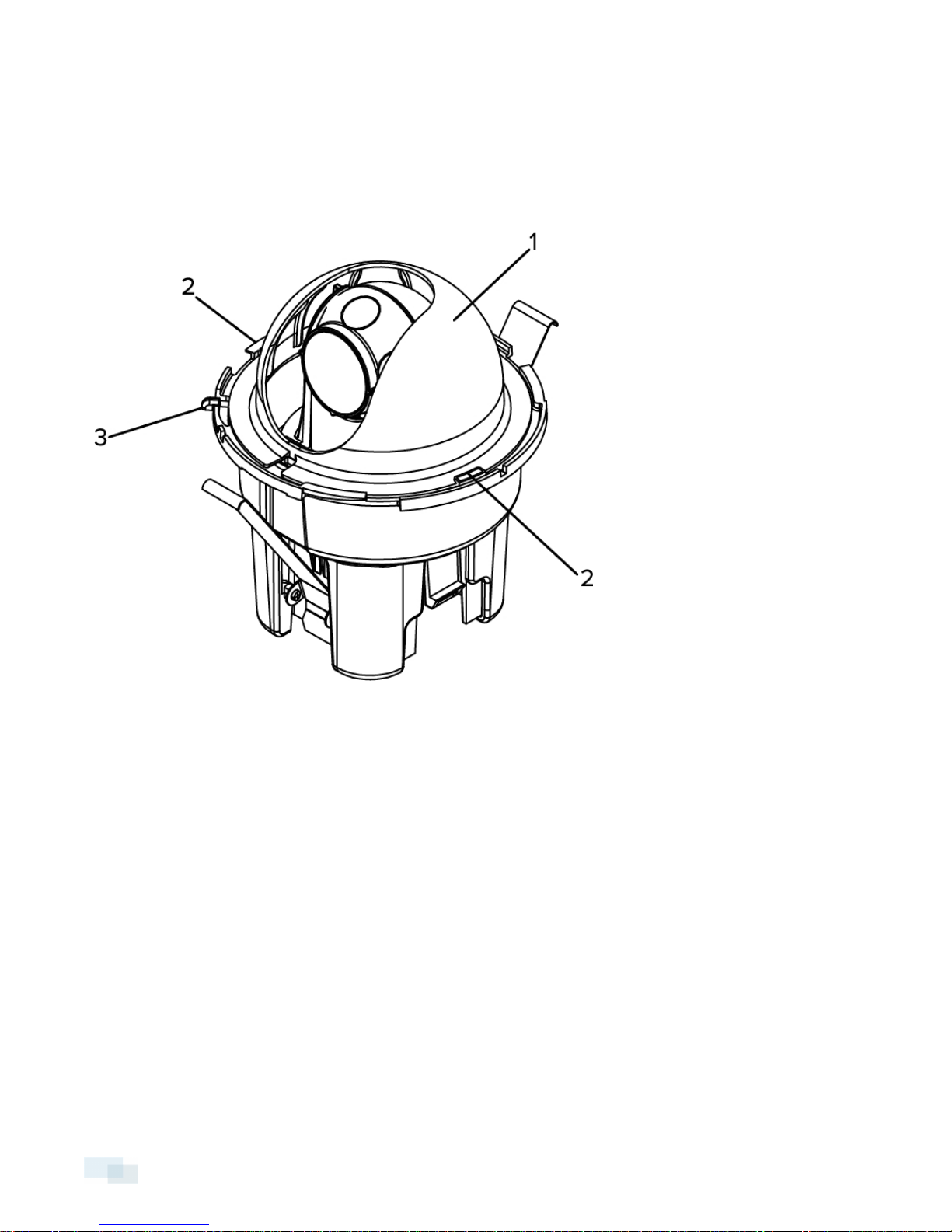
Shroud View
1. Dome Shield
Hides the camera's field of view from observers.
2. Shield Locking Tab
Locks the dome shield into place.
3. Cover Release Tab
Allows you to release and remove the dome cover.
1 Overview
Page 7
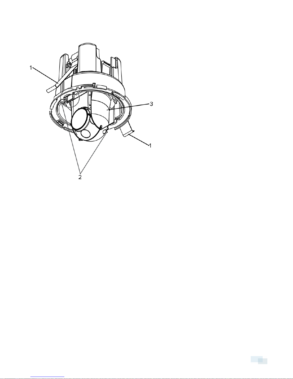
Side View
1. Locking Sheet Springs
Locks the in-ceiling camera into place.
2. Lock Release Snaps
Releases the in-ceiling lock.
3. Gimbal
Allows you to move and aim the camera after it has been installed.
SideView 2
Page 8
Front View
1. Vertical Marker
Provides a vertical reference point for the video image. Points up.
2. Horizon Markers
Provides a reference point for aligning the video image with the horizon line.
3 Front View
Page 9

Cable Assembly
1. Link LED
Indicates if there is an active connection in the Ethernet port.
2. Connection Status LED
Provides information about device operation. For more information, see LED Indicators on page13
3. Ethernet Port
Accepts power and Ethernet connection to the network.
The camera can only be powered by Power over Ethernet (PoE). Server communication and image data
transmission also occurs over this connection.
Cable Assembly 4
Page 10

Installation
Camera Package Contents
Ensure the package contains the following:
l Avigilon™ HD Micro Dome Camera
l Dome Cover
l Rubber boot
l Hole template sticker
Installation Steps
Complete the following steps to install the device:
Preparing for the Installation 6
Connecting PoE 8
Mounting the Micro Dome Camera 9
Assigning an IP Address 10
Accessing the Live VideoStream 10
Aiming the HD Micro Dome Camera 11
Installing the Dome Cover 11
5 Installation
Page 11

Preparing for the Installation
Before you can install the camera, you must first complete the following steps:
1. Use a 3" hole saw to cut a hole in the mounting surface.
l Or, use the mounting template as a guide for cutting a hole in the mounting surface.
NOTE: The camera supports a mounting surface that is between 1mm (0.04") to 25.4mm (1") thick.
2. Pull the required Ethernet cables through the mounting hole.
3. Remove the dome shield from the camera:
a. Press one side of the dome shield away from the shield locking tab that is holding it in place.
b. Lift the dome shield away from the camera.
Preparing for the Installation 6
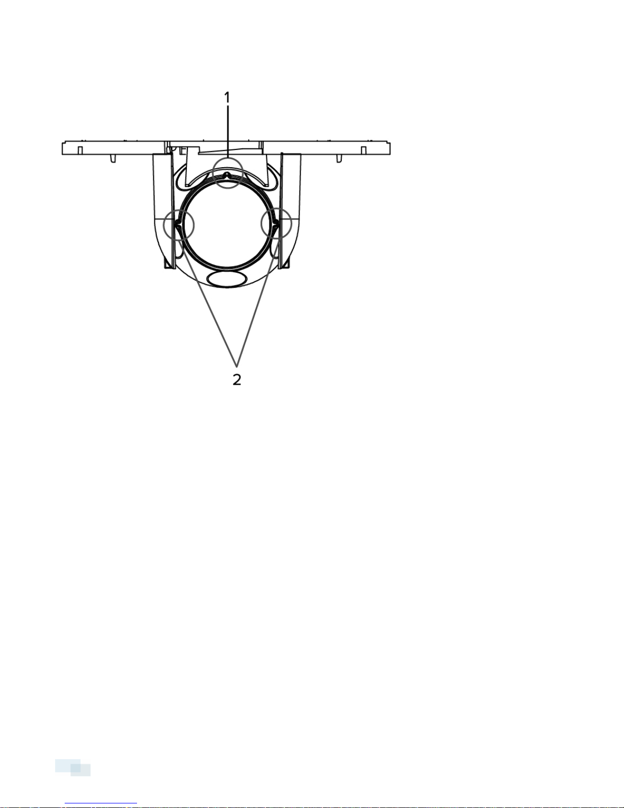
Page 12

4. Squeeze the lock release snaps together and pull the dome camera up.
The locking sheet springs are released.
7 Preparing for the Installation
Page 13

5. Rest the camera on its side to keep the locks disengaged.
Connecting PoE
The HD Micro Dome camera can only be powered by Power over Ethernet (PoE).
1. Pull the required Ethernet cable to the camera.
2. To protect the cable from dust and moisture, slide the cable through the supplied rubber boot.
3. Crimp the end of the cable with an Ethernet connector.
4. Connect the crimped cable to the Ethernet Port.
5. Check that the camera’s status LEDs indicate the correct state. See LED Indicators on page13 for more
information.
ConnectingPoE 8
Page 14

6. If you installed the rubber boot, slide the boot over the end of the cable assembly.
7. Tuck the cable assembly into the mounting hole. Make sure the cable assembly is not dangling by the
cable.
Mounting the Micro Dome Camera
1. Hold the locking sheet springs together and insert the camera into the mounting hole.
9 Mounting the Micro Dome Camera
Page 15

2. Push the camera into the hole from the gimbal until you hear it click into place.
3. Check if the camera is secure by gently pulling the gimbal.
l If the gimbal does not move, the camera is secure.
l If the gimbal comes away from the base then the camera is not secured. You may need to push
harder to secure the camera in the mounting hole. Make sure you hear a click before you continue.
Assigning an IP Address
The camera automatically obtains an IP address by default. Once connected to a network, it attempts to locate
and obtain an IP address from a DHCP server. If this fails, Zero Configuration Networking (Zeroconf) is used to
choose an IP address. When the IP address is set using Zeroconf, the IP address is in the 169.254.0.0/16 subnet.
The IP address settings can be changed using one of the following methods:
l Avigilon Camera Installation Tool software application.
l Camera's web browser interface: http://<camera IP address>/
l ARP/Ping method. For more information, see Setting the IP Address Through the ARP/Ping Method on
page16
l Network Video Management software application (for example, Avigilon Control Center).
NOTE: The default camera username is admin and the default password is admin.
Accessing the Live VideoStream
Live video stream can be viewed using one of the following methods:
l Avigilon Camera Installation Tool software application.
l Web browser interface: http://<IP address>/.
l Network Video Management software application (for example, the Avigilon Control Center software).
Assigningan IP Address 10
Page 16

NOTE: The default username is admin and the default password is admin.
Aiming the HD Micro Dome Camera
1. Turn the gimbal and rotate the camera ball until it faces the direction you want.
Use the horizon markers and the vertical marker as a guide.
Installing the Dome Cover
1. Reinstall the dome shield.
a. Insert one side of the dome shield into one of the shield locking tabs.
b. Press the opposite side of the dome shield against the shield locking tab, then push down until you
hear the dome shield click into place.
c. Rotate the dome shield so that it does not block the camera's field of view.
2. Install the dome cover.
a. Align the dome cover with the base.
b. Press the dome cover against the base then turn until it clicks into place.
11 Aiming the HD Micro Dome Camera
Page 17

For More Information
Additional information about setting up and using the device is available in the following guides:
l Avigilon Camera Installation Tool User Guide
l Avigilon Control Center Client User Guide
l Avigilon High Definition H.264 Web Interface User Guide
The manuals are available on the Avigilon website: http://avigilon.com/support-and-downloads
For More Information 12
Page 18

LED Indicators
Once connected to the network, the Connection Status LED will display the progress in connecting to the
Network Video Management software.
The following table describes what the LEDs indicate:
Connection State
Obtaining IPAddress
Discoverable
Upgrading Firmware
Connected On Connected to the Network Video Management software.
Connection Status
LED
One short flash every
second
Two short flashes
every second
Two short flashes
and one long flash
every second
Description
Attempting to obtain an IP address.
Obtained an IPaddress but is not connected to the NetworkVideo
Management software.
Updating the firmware.
13 LEDIndicators
Page 19

Removing the Dome Cover
If you ever need to adjust the camera aim, or access the cable assembly, you will need to remove the dome
cover first.
1. Press the cover release tab and twist the dome cover until it is released from the base.
The dome cover can only move in one direction.
2. To uninstall the camera, remove the dome shield then squeeze the lock release snaps together and pull
the dome camera from the mounting surface. For more information, refer to the diagrams in Preparing for
the Installation on page6
NOTE: If the camera was mounted on a thinner mounting surface, you may need to bend the locking sheet
springs flat.
Removingthe Dome Cover 14
Page 20

Reset to Factory Default Settings
If the camera no longer functions as expected, you can choose to restore the camera to its factory default
settings.
Use the firmware revert button to reset the camera.
Figure: The firmware revert button on the cable assembly.
1. Disconnect power from the device.
2. Using a straightened paperclip or similar tool, gently press and hold the firmware revert button.
3. While continuing to hold the button, power the device.
Release the button after three seconds.
CAUTION — Do not apply excessive force. Inserting the tool too far will damage the device.
15 Reset to Factory Default Settings
Page 21

Setting the IP Address Through the ARP/Ping
Method
Complete the following steps to configure the camera to use a specific IP address:
1. Locate and copy down the MAC Address (MAC) listed on the Serial Number Tag for reference.
2. Open a Command Prompt window and enter the following commands:
a. arp -s <New Camera IP Address> <Camera MAC Address>
For example: arp -s 192.168.1.10 00-18-85-12-45-78
b. ping -l 123 -t <New Camera IP Address>
For example: ping -l 123 -t 192.168.1.10
3. Reboot the camera.
4. Close the Command prompt window when you see the following message:
Reply from <New Camera IP Address>: ...
Setting the IP Address Through the ARP/PingMethod 16
Page 22

Specifications
Camera
Lens Lens 2.8mm, F2.0
Network
Network 100Base-TX
Cabling Type CAT5
Connector RJ-45
API ONVIF compliance version 1.02, 2.00, Profile S ( www.onvif.org)
Security
Streaming Protocols
Mechanical
Dimensions ØxH 90.00 mm x 107.54 mm (3.58” x 4.23”)
Distance from
mounting surface to
rear of housing
Weight
Body Plastic
Finish Plastic, RAL 9003 (RAL 9005 for -BL model)
Adjustment Range 360° pan, 90° tilt, 360° azimuth
Electrical
Power Consumption 4 W max
Power Source PoE: IEEE802.3af Class 3 compliant
Password protection, HTTPS encryption, digest authentication, WS authentication, user
access log, 802.1x port based authentication.
IPv4, HTTP, HTTPS, SOAP, DNS, NTP, RTSP, RTCP, RTP, TCP, UDP, IGMP, ICMP, DHCP,
Zeroconf, ARP, RTP/UDP, RTP/UDP multicast, RTP/RTSP/TCP, RTP/RTSP/HTTP/TCP,RTP/
RTSP/HTTPS/TCP, HTTP
61.28 mm (2.41")
150 g (5.29 oz)
+ 36 g (1.27 oz) for cable
Environmental
Operating
Temperature
Storage
Temperature
Certifications
Safety
17 Specifications
-10 °C to +50 °C (14 °F to 122 °F)
-30 °C to +70 °C (-22 °F to 158 °F)
UL 60950
CSA 60950
CB Scheme
WEEE
ROHS
C-Tick
Page 23

Electromagnetic
Emissions
Electromagnetic
Immunity
FCC Part 15 Subpart B Class B
EN 55022 Class B
IC ICES-003 Class B
EN 55024 Class B
EN 61000-4-2
EN 61000-4-3
EN 61000-4-4
EN 61000-4-5
EN 61000-4-6
EN 61000-4-11
Specifications 18
Page 24

Limited Warranty & Technical Support
Avigilon warrants to the original consumer purchaser, that this product will be free of defects in material and
workmanship for a period of 3 years from date of purchase.
The manufacturer’s liability hereunder is limited to replacement of the product, repair of the product or
replacement of the product with repaired product at the discretion of the manufacturer. This warranty is void if
the product has been damaged by accident, unreasonable use, neglect, tampering or other causes not arising
from defects in material or workmanship. This warranty extends to the original consumer purchaser of the
product only.
AVIGILON DISCLAIMS ALL OTHER WARRANTIES EXPRESSED OR IMPLIED INCLUDING, WITHOUT LIMITATION,
ANY IMPLIED WARRANTIES OF MERCHANTABILITY OR FITNESS FOR A PARTICULAR PURPOSE, EXCEPT TO
THE EXTENT THAT ANY WARRANTIES IMPLIED BY LAW CANNOT BE VALIDLY WAIVED.
No oral or written information, advice or representation provided by Avigilon, its distributors, dealers, agents or
employees shall create another warranty or modify this warranty. This warranty states Avigilon’s entire liability
and your exclusive remedy against Avigilon for any failure of this product to operate properly.
In no event shall Avigilon be liable for any indirect, incidental, special, consequential, exemplary, or punitive
damages whatsoever (including but not limited to, damages for loss of profits or confidential or other information,
for business interruption, for personal injury, for loss of privacy, for failure to meet any duty including of good faith
or of reasonable care, for negligence, and for any other pecuniary or other loss whatsoever) arising from the use
of or inability to use the product, even if advised of the possibility of such damages. Since some jurisdictions do
not allow the above limitation of liability, such limitation may not apply to you.
This Limited Warranty gives you specific legal rights and you may also have other rights which vary from
jurisdiction to jurisdiction.
Warranty service and technical support can be obtained by contacting Avigilon Technical Support by phone at
1.888.281.5182 or via email at support@avigilon.com.
19 Limited Warranty & Technical Support
 Loading...