

Page 1
Page 2

Page 3

Page Chg
Cover…...0
Page #......1
TOC-1......1
TOC-2.…..1
1-1……….1
1-2……….0
1-3……….1
1-4……....1
1-5……....1
1-6…….…1
1-7…….…1
1-8…….…1
1-9…….…1
1-10……...1
1-11……..1
1-12……..1
1-13……..2
1-14……..1
1-15……..1
1-16……..1
1-17……..1
1-18……..1
2-1……….0
2-2……….0
Page Chg
2-3……….1
2-4……….0
3-1……….0
3-2……….0
3-3……….1
3-4……….0
3-5……….0
3-6……….0
3-7……….0
3-8……….0
3-9……….1
3-10……..0
3-11……..0
3-12……..0
3-13……..0
3-14……..1
3-15……..1
4-1……….1
4-2……….1
4-3……….0
4-4……….0
4-5……….1
4-6……….0
4-7……….0
Page Chg
4-8…….…0
4-9……….0
4-10……..0
4-11……..1
4-12……..1
5-1……….0
5-2……….1
5-3……….1
5-4……….0
5-5……….1
5-6……….1
5-7……….1
5-8……….0
5-9……….0
5-10……..0
6-1……….1
6-2…….…1
6-3…….…1
6-4……….1
6-5……….1
6-6……….1
Indx-1…...1
IBC……....0
OBC…..…1
Change 1
Page 4

1-2 System Overview
DFC100 Digital Autopilot | PILOT GUIDE
TABLE OF CONTENTS
1
System Overview ..............................................................1-2
FUNCTIONAL OVERVIEW ..........................................................1-3
GENERAL AUTOPILOT OPERATIONS .......................................1-4
Basic Autopilot Operation ...................................................................... 1-4
Capture And Hold Operation ................................................................. 1-4
Target (Bug) Setting .............................................................................. 1-4
Aural Alerts ........................................................................................... 1-5
Armed vs Engaged Mode Indications .................................................... 1-6
Mode Transition Indication .................................................................... 1-6
Manual Electric Trim Disconnect ........................................................... 1-7
Envelope Protection .............................................................................. 1-8
Full-Time Envelope Alerting .................................................................. 1-9
Barometer Setting Adjustment ............................................................ 1-12
Engagement and Hold limits ............................................................... 1-13
Comparators ....................................................................................... 1-14
Autopilot Engagement ......................................................................... 1-15
Autopilot Disengagement .................................................................... 1-15
FD vs. AP ........................................................................................... 1-16
PFD Annunciations ............................................................................. 1-17
2 Normal Startup Sequence ................................................2-2
POWER CONSIDERATIONS .......................................................2-2
SELF-TEST/ALIGNMENT ............................................................2-2
BRIGHTNESS CONTROLS .........................................................2-2
PRE-FLIGH T TES T ......................................................................2-3
BEFORE TAKEOFF TECHNIQUES .............................................2-4
3 Climb-out/Enroute .............................................................3-2
NORMAL OPERATING MODES ..................................................3-2
Pitch Mode ............................................................................................ 3-2
Roll Mode ............................................................................................. 3-2
Vectors (HDG) Mode ............................................................................ 3-3
Navigation (NAV) Mode ........................................................................ 3-4
Altitude Hold (ALT) Mode ...................................................................... 3-5
Indicated Airspeed (IAS) Hold Mode ..................................................... 3-5
Vertical Speed (VS) Hold Mode ............................................................ 3-6
VNAV Mode .......................................................................................... 3-7
Altitude Capture Mode ........................................................................ 3-10
Straight and Level ............................................................................... 3-12
Pilot Selectable Intercepts ................................................................... 3-13
Control Wheel Steering Mode ............................................................. 3-14
Take off/Go Around (TO/GA) Mode ..................................................... 3-15
4 Approach Procedures ......................................................4-2
GENERAL BEHAVIOR .................................................................4-2
APPROACH MODES ...................................................................4-2
WAAS Approaches ............................................................................... 4-2
Non-WAAS GPS approach (RNAV or Overlay or LNAV) ....................... 4-5
VOR approach ...................................................................................... 4-5
Localizer approach ................................................................................ 4-6
Change 1
Page 5

ILS approach including glide slope intercept ......................................... 4-7
Procedure Turn ILS or Localizers .......................................................... 4-8
Back course approaches ....................................................................... 4-9
Missed Approach ................................................................................ 4-10
Take off/Go Around (TO/GA) Mode ..................................................... 4-11
5 Abnormal Procedures ......................................................5-2
GENERAL FAILURE MODE INFORMATION ...............................5-2
OTHER ERROR MODES .............................................................5-5
ALERTS ........................................................................................5-7
LOSS OF ENGINE .....................................................................5-10
6 Limitations and Perfo rmance ..........................................6-2
LIMITATIONS ...............................................................................6-2
SOFTWARE COMPATABILITY AND NOTES ..............................6-4
GENERAL PERFORMANCE – CIRRUS AIRCRAFT ...................6-5
PERFORMANCE IN PITCH TRIM-ONLY AIRCRAFT ..................6-6
PERFORMANCE IN NON-CIRRUS AIRCRAFT...........................6-6
Index ............................................................................................ 1
Change 1
Page 6

Page 7

System Overview 1-1
1 System Overview ..............................................................1-2
FUNCTIONAL OVERVIEW ..........................................................1-3
GENERAL AUTOPILOT OPERATIONS .......................................1-4
Basic Autopilot Operation ...................................................................... 1-4
Capture And Hold Operation ................................................................. 1-4
Target (Bug) Setting .............................................................................. 1-4
Aural Alerts ........................................................................................... 1-5
Armed vs Engaged Mode Indications .................................................... 1-6
Mode Transition Indication .................................................................... 1-6
Manual Electric Trim Disconnect ........................................................... 1-7
Envelope Protection .............................................................................. 1-8
Full-Time Envelope Alerting .................................................................. 1-9
Barometer Setting Adjustment ............................................................ 1-12
Engagement and Hold limits ............................................................... 1-13
Comparators ....................................................................................... 1-14
Autopilot Engagement ......................................................................... 1-15
Autopilot Disengagement .................................................................... 1-15
FD vs. AP ........................................................................................... 1-16
PFD Annunciations ............................................................................. 1-17
Change 1
Page 8
1-2 System Overview
1 System Overv i ew
This manual assumes that the pilot is appropriately licensed, is
proficient in operation of the aircraft and its equipment, and is in
compliance with all Federal Aviation Regulations (FARs).
All images contained in this manual are for reference use only,
and are subject to change.
Avidyne strongly recommends that pilots use the DFC100 system
only under VFR conditions until completely familiar with its
operation and use.
Boxed areas marked as NOTE within this manual identify certain
situations or areas of operation having safety implications. While
it is important for the operator to be familiar with all of the
information in the manual, it is essential to the safe use of the
DFC100 that pilots give careful attention to the material contained
within these NOTEs.
Boxed areas marked as WARNING within this manual identify
certain situations or areas of operation having unique and
heightened safety implications.
In order to avoid a diversion of attention from the task of safely
taxiing, pilots should avoid performing the described cockpit tasks
while the aircraft is in motion during taxi.
It remains the pilot’s duty to monitor the autopilot for proper
function upon activation and during use.
Internal DFC100 data logs are property of Avidyne.
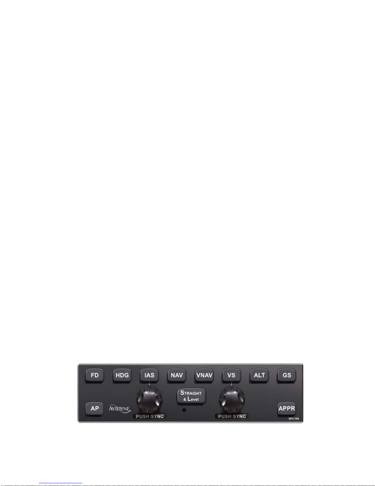
DFC 100 Digital Flight Control Panel
Page 9

System Overview 1-3
FUNCTIONAL OVERVIEW
The Avidyne DFC100 autopilot supports the following functions:
• Flight Director
• Heading Capture/Hold
• NAV Tracking
• Vectors Mode
• VNAV Tracking
• Approach Mode (includes LOC, ILS, VOR, BC, LPV,
LNAV/VNAV, LNAV+V)
• Altitude Hold
• Altitude Capture
• Vertical Speed Hold
• Indicated Airspeed Mo de
• Straight and Level
• Pilot Selectable Interc ept A ngl es
• Control Wheel Steering (not available in all aircraft)
• Takeoff/Go Around (TO/GA) Mode (not available in all
aircraft)
• Speed-based Envelope Protection
• Full-time Envelope Alerting
NOTE
Envelope Protection vs. Envelope Alerting
There is a distinction between Envelope Protection
and Full-time Envelope Alerting. Envelope
Protection will resu lt in acti ve driving of the flight
control surfaces by the autopilot. Full-time
Envelope Alerting will on l y provide visual and aural
alerting but it is up to the pilot to manually make any
control surface changes.
Change 1
Page 10

1-4 System Overview
GENERAL AUTO PILOT O PERATIONS
NOTE
Avoid Pilot Flight Control Input In AP
The pilot should not make any input to the flight
controls while the autopilot is engaged.
BASIC AUTOPILOT OPERATION
The DFC100 autopilot always has both a lateral and vertical
mode active when engaged. If a specific lateral mode has not
been selected by the pilot, then the system defaults to Roll Hold
mode. If a specific vertical mode has not been selected by the
pilot, then the system defaults to Pitch Hold mode.
CAPTURE AND HOLD OPERATION
A single button press will typically engage the mode pressed and
arm a logical choice that will capture if the capture criteria are
met. For example, pressing IAS or VS will hold the indicated or
vertical speed and
arm altitude. Another example is pressing the
HDG button will engage heading mode and arm NAV mode (if
Primary Nav LSK is set to FMS).
If you want the autopilot to remain in the selected mode (e.g. stay
in IAS mode and not capture altitude even if the aircraft flies
through the altitude bug setting), press the desired button (IAS in
this example) a second time to disarm the capture. The blue
armed indicator (ALT in this example) on the autopilot and the
PFD page will extinguish.
TARGET (BUG) SETTING
The primary location for setting both the IAS and VS targets are
via the dedicated knobs on the autopilot control head.
The primary location for setting the HDG and ALT targets are via
the dedicated knobs on the keyboard.
Change 1
Page 11

System Overview 1-5
AURAL ALERT S
Aural alerting, through the aircraft intercom system, is provided
for warnings from the autopilot. In the context of the bullets
below, “coupled” describes the condition when the autopilot
servos are flying the airplane and “non-coupled” describes the
condition when the servos are not flying the airplane and instead,
the pilot is expected to follow the flight director command bars.
Specifically, aural alerts as defined in the parenthesis are
provided under the following conditions:
Autopilot Disengagement (Approximately 16 disconnect
beeps)
Underspeed during coupled operations (“Speed
Protection Active”)
Overspeed during coupled operations (“Speed Protection
Active”)
Underspeed during non-coupled operations (“Caution,
Underspeed”)
Overspeed during non-coupled operations (“Caution,
Overspeed”)
Dual AHRS equipped systems: Attitude and Heading
Reference System (AHRS) Miscompare (“Gyro
Miscompare”)
Single AHRS equipped systems: Attitude and Heading
Reference System (AHRS) and Turn Coordinator
Miscompare (“Gyro Miscompare”)
Single AHRS equipped systems: Crosscheck Attitude 1
(“Gyro Miscompar e”)
POH bank limit exceeded (“Caution, Excessive Bank”)
POH flap extension speed exceeded (“Caution, Flap
Overspeed”)
Change 1
Page 12
1-6 System Overview
ARMED VS ENGAG ED MODE INDICATIONS
The DFC100 autopilot has more readily distinguishable armed vs.
engaged modes in order to provide the user higher awareness of
the current autopilot state and upcoming state transitions.
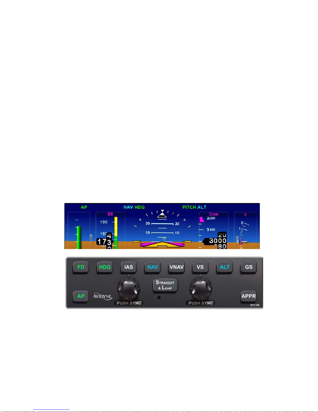
An armed mode is defined as a state that will be captured when
and if the airplane crosses that target. Armed modes are
indicated by a cyan (blue) color on both the autopilot control
panel and on the PFD mode annunciator strip.
An engaged mode is defined as a state that the autopilot is
holding. Engaged modes are indicated by a green color on both
the autopilot control panel and on the PFD mode annunciator
strip. One exception is that when AP is on, both “FD” and “AP”
are not lit on the PFD mode annunciator strip – FD is always on
with AP.
The images below demonstrate the armed and engaged coloring
on both the display and the autopilot control head. In this
example, Heading (HDG) and Pitch modes are engaged and Nav
mode and Alt are armed.
MODE TRANSITION INDICATION
Automatic transition from armed (cyan) to engaged (green) states
is indicated by the cyan armed button on the autopilot control
Change 1
Page 13

System Overview 1-7
panel and mode annunciation on the PFD changing to green and
flashing for up to 10 seconds.
Note that the engaged (green) autopilot mode annunciators will
also flash when in underspeed or overspeed conditions. This
flashing is intended to gain the pilot’s attention and to indicate
that while the modes are still engaged (green), the underspeed or
overspeed condition may be affecting the system’s ability to hold
the target value. As soon as the underspeed or overspeed
condition is no longer true, the annunciators stop flashing and the
system reacquires the target values as required.
MANUAL ELECTRIC TRIM DISCONNECT
Use of the manual electric trim (MET) in the pitch axis via the
cockpit controls will result in the autopilot disconnecting and then
the trim running as commanded by the MET control.
NOTE
Trim Behavior in Cirrus Aircraft
For Cirrus aircraft equipped with a pitch servo,
actuating the trim switch will dis connec t the AP . For
Cirrus aircraft that are equipped with pitch trim only,
actuating the trim switch will have no effect during
autopilot operations (trim will not adjust and the AP
will not disengage). For predictability of results,
pilots of Cirrus aircraft should therefore determine
whether the aircraft is equipped with a pitch servo or
pitch trim before actuating the trim switch in IMC
conditions.
Change 1
Page 14

1-8 System Overview
ENVELOPE PRO T EC TION
The DFC100 system provides speed-based Enve lop e Protec t ion
(underspeed and overs pee d warn ings and pr otection) when in
any coupled autopilot mode.
NOTE
No Envelope Protection in Flight Director Mode
Envelope Protection is not provided during flight
director-only (non-coupled) operat ions .
NOTE
Aircraft Stall Possible with Envelope Protection
Conditions can exist where an aircraft can be placed
in an attitude and/or configuration that would exceed
the capability of the Envelope Protection system to
prevent a stall.
When the servos are engaged (AP mode), the likelihood that a
command can be made which results in an autopilot induced stall
is significantly reduced over conventional autopilots. If for
example, a positive rate of climb was commanded and a low
power setting is being held, the autopilot will attempt to achieve
the commanded state but as the energy of the airplane decays to
approximately 1.2 V
s
, the autopilot will adjust bank angle and then
pitch angle as required to m aintain no lower tha n 1.2 V
s
. Bank
angle may be reduced before pitch is adjusted in an effort to
avoid even entering envelope protection. As soon as bank angle
is adjusted by the autopilot, the pilot is alerted through visual
means on the PFD (“UNDERSPEED” text alert and any engaged
(green) autopilot mode annunciator will flash) and as soon as
pitch is adjusted, the pilot is alerted through the same visual
means on the PFD, and aural alerting in the headsets (“SPEED
PROTECTION ACTIVE”). In all cases, when underspeed
protection is active, maximum bank angle will be reduced,
typically to 5 degrees.
Change 1
Page 15

System Overview 1-9
Similarly, envelope protection will provide high-speed protection
and alerting near V
ne
. In this case, as Vne is approached in AP
mode, the autopilot will adjust pitch as required to maintain an
airspeed near V
ne
. Aircraft bank angle is not adjusted by the
autopilot during overspeed protection. Depending on conditions
(e.g. rapidly changing airspeed, turbulence, etc.), it is possible for
V
ne
to be exceeded. An overspeed condition is annunciated to the
pilot via an “OVERSPEED” text alert on the PFD, a “SPEED
PROTECTION ACTIVE” aural alert in the headsets, and by a
flashing of any engaged (green) autopilot mode annunciators.
The DFC100 takes flap position into account in Envelope
Protection and Envelope Alerting calculations and as a result, the
definition of V
s
, changes depending on flap position.
NOTE
Envelope Protection During Icing Conditions
The DFC100 autopilot is not to be used during icing
conditions in any non-FIKI approved aircraft, or
during severe icing conditions in any FIKI approved
aircraft. The autopilot does not have any kind of
AOA or icing input and therefore does not register
changing aircraft dynamics during icing conditions.
Therefore, Envelope Protection is not effective
under icing conditions.
FULL-TIME ENVELOPE ALERTING
The DFC100 autopilot provides speed-based and attitude-based
envelope alerting when ev er the autopi lot is not
engaged (servos
not coupled).
Full-time Envelo pe Aler ti ng is provid ed dur in g flight dir e ctor
operations (servos not coupled). Full-time Envelope Alerting is
also provided even when the autopilot and flight director are off
and the autopilot is in the standby position as noted by the AP
READY mode annunciator on the top strip of the PFD pages.
Change 1
Page 16

1-10 System Overview
Full-time Envelope Alerting is triggered when the DFC100
recognizes an underspeed, overspeed or excessive bank angle
condition and will alert the pilot via text alerts on the PFD pages
and aural alerts.
NOTE
Suppression of Full-time Envelo p e Alerting
Full-time Envelo pe Aler ti ng is suppres s ed duri ng
very low power (near idle) conditions when flaps are
set to the full-flap position in order to minimize
nuisance calls in the landing phase. Full-time
Envelope Alerting is also suppressed anytime
Indicated Airspeed is less than 50 KIAS in order to
minimize nuisance calls during rollout and taxi.
In Flight Director operations, the flight director command bars will
continue to direct a pilot to fly to the commanded pitch and roll
targets as defined by the bug and nav source entries but if an
underspeed condition is recognized, a “UNDERSPEED” text alert
is displayed along the top edge of the PFD pages and a
“CAUTION, UNDERSPEED” aural alert is played in the headsets
and is repeated approximately every 6 seconds until the condition
is no longer valid. The autopilot mode annunciators do not flash
during Envelope Alerting. The trigger for this Envelope Alerting
underspeed alert is when the system has determined 1.2V
s
has
been reached. Flap position, bank angle and g-loading are taken
into account to define V
s
at any point in time (assumes max gross
weight).
Similarly, during high-speed flight director operations, the flight
director command bars will continue to direct a pilot to fly to the
commanded pitch and roll targets as defined by the bug and nav
source entries but if an overspeed condition is recognized, a
“OVERSPEED” text alert is displayed along the top edge of the
PFD pages and a “CAUTION, OVERSPEED” aural alert is played
in the headsets and is repeated approximately every 6 seconds
until the condition is no longer valid. There is no flashing of any
autopilot mode annunciator during Envelope Alerting. The trigger
for this Envelope Alerting overspeed alert is when the system has
determined V
ne
is about to reached.
Change 1
Page 17

System Overview 1-11
If the autopilot is not engaged in any Autopilot or Flight Director
modes and is in the standby condition, as indicated by the green
“AP READY” annunciator on the PFD and no green or cyan lights
on the autopilot control head, Full-time Envelope Alerting is still
active. In this case, there are no flight director command bars
present and no autopilot mode annunciators aside from the “AP
READY” one along the top edge of the PFD.
If an underspeed condition is recognized, an “UNDERSPEED”
text alert is displayed along the top edge of the PFD pages and a
“CAUTION, UNDERSPEED” aural alert is played in the headsets
and is repeated approximately every 6 seconds until the condition
is no longer valid. The trigger for this Envelope Alerting
underspeed alert is when the system has determined 1.2V
s
has
been reached. Flap position, bank angle and g-loading are taken
into account to define V
s
at any point in time. One common
scenario this capability is designed to alert against is a traffic
pattern stall.
Similarly, on the high-speed end of the spectrum with the
autopilot in the standby condition (green “AP READY” along the
top strip of the PFD pages), if an overspeed condition is
recognized, a “OVERSPEED” text alert is displayed along the top
edge of the PFD pages and a “CAUTION, OVERSPEED” aural
alert is played in the headsets and is repeated approximately
every 6 seconds until the condition is no longer valid. The trigger
for this Envelope Alerting overspeed alert is when the system has
determined V
ne
is about to reached.
NOTE
Triggering of Overspeed Alerts
Full-time Envelo pe Aler ti ng prov ides ov er speed
alerting as Vne is approached. The software uses a
combination of speed rate, pitch rate, bank and
indirectly, g-onset rate to determine when to issue
the alarm. If it detects the aircraft is actually
recovering as speed approaches Vne, the
overspeed alert may be delayed until right at, or
slightly over, Vne.
Change 1
Page 18

1-12 System Overview
Finally, if at any time and in any flight director or standby state,
the system detects an excessive bank condition, a “BANK LIMIT”
text alert is displayed along the top edge of the PFD pages and a
“CAUTION, EXCESSIVE BANK” aural alert is played in the
headsets and is repeated approximately every 6 seconds until the
condition is no longer valid. The trigger for this Envelope Alerting
excessive bank limit is when the system has determined that the
lesser of aircraft category or aircraft POH bank angle limits has
been exceeded. This number is typically 60 degrees of bank.
If “AP READY” or “FD” are not displayed on the PFD page, Fulltime Envelope Alerting may not be available.
To disable Full-time Envelope Alerting, pull the autopilot circuit
breaker.
BAROMETER SETTING ADJUSTMENT
Upon input of a new barometric altimeter setting, the autopilot
automatically re-captures the previously set target altitude,
without further action required from the pilot. For ex am ple, if the
autopilot was in Altitude Hold, changing the barometric pressure
setting will result in the autopilot automatically correcting the
appropriate amount to re-capture the pr e vious MSL altitude hold
target.
Change 1
Page 19

System Overview 1-13
ENGAGEMENT AND HOLD LIMITS
The DFC100 has maximum engagement limits beyond which the
autopilot may
not allow a mode to be selected, and maximum
hold limits for various parameters. The engagement limits of the
autopilot are wider than the hold limits. If the autopilot is engaged
between the maximum engagement limits and the maximum hold
limits, the autopilot will reduce the value to be within the
published maximum hold limits.
The maximum engagement and hold limits are as follows:
Autopilot Mode Maximum
Demonstrated
Engagement Limits
Maximum
Hold Limits
Roll Hold
±60° bank ±22°bank
Heading
±60° bank ±22° bank (but
typically holds 1
stnrd rate of turn)
Pitch Hold
±30° pitch -10° to +15° pitch
IAS Hold 20 KIAS to Vne 1.2Vs to 185 KIAS
VS Hold ±1600 fpm ±1600 fpm
Straight and
Level
±60° bank, ±30° pitch Will stabilize in +2°
pitch and zero
bank angle
Localizer, VOR,
GPS approach
Capture
Not Applicable
±22° bank
Localizer, VOR,
GPS approach
Track
Not Applicable
±10° bank
Change 2
Page 20

1-14 System Overview
COMPARATORS
There are various comparators running in the IFD and DFC100
system as noted in the chart below. If conflicting information is
provided, the comparator identifying the conflict with the
accompanying pilot indication and autopilot behavior is noted in
the table below:
Type of
Comparator
Indication to Pilot Autopilot behavior
Internal kinematic
comparator within
the AHRS
(compares AHRS
state data with
itself, eg. turn rate
without
accompanying
heading change,
etc)
“CROSSCHECK
ATTITUDE 1”
annunciation on
PFD page for minor
issues and indicator
removal and
replacement by
“Red-X” for major
issues
Dual AHRS
Systems: No
autopilot disconnec t
Single AHRS
Systems: Autopilot
will disconnect with
a “Crosscheck
Attitude 1” but will
allow manual reengagement by the
pilot.
Dual AHRS
Systems: AHRS-to-
AHRS Comparator
Single AHRS
Systems: AHRS-to-
Turn Coordinator
(TC) Comparator
Miscompare Alert
message(s)
presented to the
pilot on the IFD
(“AHRS
Miscompare” CAS
message) and in
the headset
(“GYRO
MISCOMPARE”)
Autopilot will
disconnect with a
Pitch or Roll
miscompare (dual
AHRS systems) but
not
for an AHRS-TC
miscompare (single
AHRS systems)
and allow manual
re-engagement by
the pilot after
selection by the
pilot of the operable
AHRS by reference
to the standbys.
Change 1
Page 21

System Overview 1-15
AUTOPILOT ENGAGEMENT
From a standby state (autopilot has power, “AP READY”
displayed but no modes are engaged and the airplane is within
the engagement limits defined above), pressing any button on the
DFC100 (except GS and APPR) will engage the autopilot. If a
specific lateral and/or vertical mode is not pressed, the DFC100
will default to ROLL hold mode in the lateral channel and PITCH
hold mode in the vertical channel.
From a standby state:
Press “AP” : autopilot engages in ROLL and PITCH and
will hold whatever bank and pitch was present at time of
pressing (within maximum hold limits)
Press “FD” : flight director (servos not coupled) engages
in ROLL and PITCH and will command via the green
flight director command bars whatever bank and pitch
was present at time of pressing (within maximum hold
limits). It is still up to the pilot to maneuver the plane as
required to follow those command bars.
Press “STRAIGHT & LEVEL” : autopilot engages and
drives the airplane from whatever attitude it is in to zero
bank and a small positive pitch that approximates level
flight.
Press any other button(s) (except GS or APPR) on the
autopilot: autopilot engages and will enter the modes as
commanded.
AUTOPILOT DISENGAGEMENT
The autopilot can be disengaged using any one of the following
methods:
Press the AP Disconnect switch on the control yoke (in
some aircraft, this is a dedicated button and in others, it
requires a push in of the trim hat on the yoke);
Activate the pitch-axis trim switch on the control yoke
(this does not apply on pitch trim-only aircraft);
Change 1
Page 22

1-16 System Overview
Press the “AP” button on the autopilot control panel
(servos will disconnect but the flight director will remain
active);
Pull the circuit breaker(s) controlling the power to the
autopilot.
For those aircraft with the stall warning wired directly to the
autopilot, the autopilot will dis c onn ect if the aircraft stall warning
alarm is triggered.
In most cases, the autopilot disconnect will be accompanied by a
16-beep disconnect aural alert. This tone can be muted by
another press of the AP Disconnect switch on the control yoke.
FD vs. AP
The status of the reference bugs, autopilot annunciators, autopilot
control head, and flight director steering command bars indicate
when the IFD is coupled with the autopilot.
A solid magenta heading, altitude, IAS or VS bug indicates that
function is currently coupled to an engaged or armed mode of the
autopilot or the flight director. A hollow
magenta bug indicates
that the function is not currently coupled to the autopilot or flight
director in an engaged or armed mode. In other words, the
autopilot and flight director, are ignoring any hollow magenta bug.
The flight director command bars will indicate the required
steering of the aircraft to achieve the commanded tracking of the
autopilot. In full autopilot mode, both the “AP” and “FD” buttons
will be lit on the autopilot control panel and “AP” will be displayed
in the autopilot annunciation field on the display, the command
bars will be visible and magenta and the aircraft should track
those bars very precisely.
In Flight Director only mode, only the “FD” button (and not the
“AP” button) will be lit on the autopilot control panel and “FD” will
be displayed in the autopilot annunciation field on the displa y, the
command bars will be visible and green, and the pilot is expected
to use the flight controls as required to track those bars. In Flight
Director only mode, the pilot is hand flying the airplane and is
expected to guide the aircraft such that the yellow aircraft
reference symbol is tucked into the steering command bars.
Change 1
Page 23
System Overview 1-17
The flight director command bars in a DFC100 autopilot are
designed for easy use and improved performance during
uncoupled autopilot operations.
During coupled operations (both “AP” and “FD” buttons lit),
pressing the “FD” button will have no effect. Pressing the “AP”
button in this state will toggle the “AP” mode on/off. It is a good
way to disconnect the servos but continue to have flight director
command bars present. The recommended way to disengage
both the “AP” and “FD” modes will be via trim or the AP
Disconnect switch on the control yoke as described above.
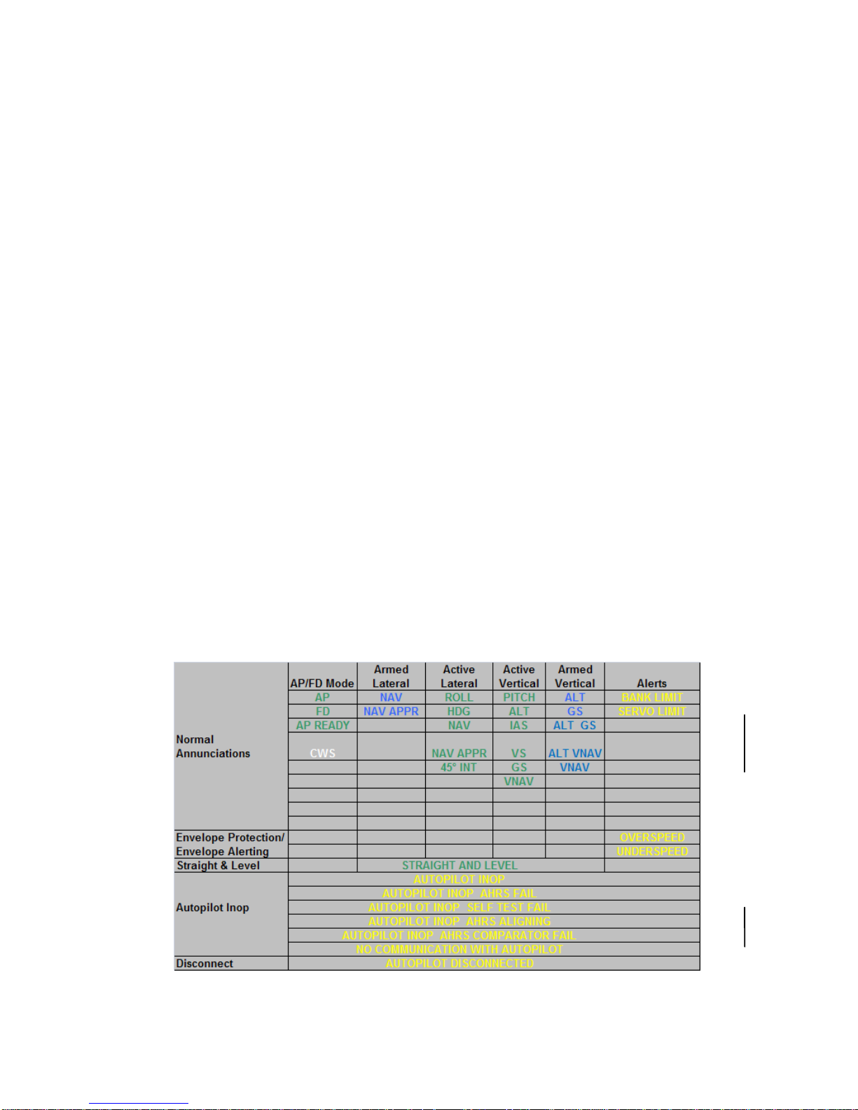
PFD ANNUNCIATIONS
The top strip of the PFD page is dedicated for autopilot mode
annunciators. Active modes are depicted in green and armed
modes are depicted in cyan. Alerts are depicted in yellow and
are listed in order of priority. If multiple alerts are received, then
the highest priority message is displayed.
Whenever “UNDERSPEED” or “OVERSPEED” are displayed
while the autopilot is coupled, all engaged (green) autopilot mode
annunciators will flash.
The tables below are a listing of all annunciations that are
possible with the DFC100 system.
DFC100 Annunciations
Change 1
Page 24

Page 25

Normal Startup Sequence 2-1
2 Normal Startup Sequence ................................................2-2
POWER CONSIDERATIONS .......................................................2-2
SELF-TEST/ALIGNMENT ............................................................2-2
BRIGHTNESS CONTROLS .........................................................2-2
PRE-FLIGH T TES T ......................................................................2-3
BEFORE TAKEOFF TECHNIQUES .............................................2-4
Page 26

2-2 Normal Startup Sequence
2 Normal Startup Sequence
POWER CONSIDERATIONS
The DFC100 consumes 0.25A when no servos are in operation
and up to 0.9A with all servos operating at 100% duty cycle.
There is no on/off switch for the DFC100. As soon as the power
bus is active through normal aircraft checklist steps, the autopilot
will power up.
SELF-TEST/ALIGNMENT
The DFC autopilot requires two events to be fully functional. The
first is a successful completion of a self-test and the second is a
successful alignment of all ADAHRS. To assure readiness of the
autopilot for flight, it is also recommended that the pilot conduct
the Pre-Flight Test described later in this chapter.
DFC self-test takes less than 5 seconds following power
application. The normal self-test indications are a lighting of
lights on the autopilot control panel, dwelling approximately 1-2
seconds on each color. The lighting color order is White-CyanGreen-White. Self-test should be considered a success after the
button lighting with no associated failure message along the top
strip of the PFD page.
The top strip of the PFD page will display an annuncia t ion that the
autopilot is INOP (inoperative) while the ADAHRS is aligning.
The message will explicitly state that the ADAHRS is aligning.
Any other anomaly during alignment is displayed as a descriptive
annunciation along that same top annunciator strip on the PFD.
BRIGHTNESS CONTROLS
The autopilot control head button and knob lig hti ng is c ontr olled
via the cockpit dimming controls/rheostats.
If the autopilot control panel appears “inoperative” or nonresponsive from a lighting perspective, check the instrument
lighting rheostat on the bolster to ensure it is not set to a night
position.
Page 27

Normal Startup Sequence 2-3
PRE-FLIG HT TEST
1. Ensure “AP READY” is displayed on PFD annunciator
strip
2. Press AP button on autopilot control head
a. Ensure AP button is lit in green
b. Ensure “AP”, “ROLL”, “PITCH” annunciations are
depicted in green on the PFD annunci ator strip
and “ALT” is depicted in cyan
3. Set the Heading Bug to be approximately 90 degrees off
current aircraft heading
4. Press HDG button on autopilot control head
a. Ensure HDG button is lit in green
b. Ensure the ailerons are being driven in the proper
direction by the servos (movement is slow and
can be hard to see)
c. Ensure “HDG” annunciation has replaced ROLL
annunciation and that it is depicted in green on
the PFD annunciator strip (“SERVO LIMIT” may
also be displayed along the right edge – this is
normal in some aircraft)
5. Press the AP Disconnect switch on the control yoke
a. Ensure the aural autopilot disconnect tone is
heard in the headset
b. Ensure “AUTOPILOT DISCONNECTED”
annunciation is depicted in yellow on the PFD
c. Ensure “AP READY” annunciation is then
depicted in green on the PFD annunciator strip
6. Trim the aircraft to the appropriate pre-takeoff position in
accordance with normal aircraft checklist procedures.
Change 1
Page 28

2-4 Normal Startup Sequence
NOTE
Preflight Test Does Not Test Every Aspect of AP
The Pre-Flight test of the DFC100 auto pi lot outlined
above will check the functionality of such items as
the ability of the autopilot to engage and disconnect,
the ability of the autopilot to engage the roll axis
control surfaces, and the communications between
the autopilot and the IFD. However, the Pre-Flight
test does not check the function of every item
essential to the use of the autopilot. It remains the
pilot’s duty to monitor the autopilot for proper
function upon activation and during use.
BEFORE TAKEOFF TECHNIQUES
A normal technique is to set up the desired autopilot targets while
still on the ground (e.g. IAS or VS, ALT and HDG bugs).
Neither the Flight Director nor Autop ilot shou ld be eng a ged unt il
in-flight and at a safe altitude, a minimum of 200’ AGL.
Page 29

Page 30

2-2 Climb-out/Enroute
3 Climb-out/Enroute .............................................................3-2
NORMAL OPERATING MODES ..................................................3-2
Pitch Mode ............................................................................................ 3-2
Roll Mode ............................................................................................. 3-2
Vectors (HDG) Mode ............................................................................ 3-3
Navigation (NAV) Mode ........................................................................ 3-4
Altitude Hold (ALT) Mode ...................................................................... 3-5
Indicated Airspeed (IAS) Hold Mode ..................................................... 3-5
Vertical Speed (VS) Hold Mode ............................................................ 3-6
VNAV Mode .......................................................................................... 3-7
Altitude Capture Mode ........................................................................ 3-10
Straight and Level ............................................................................... 3-12
Pilot Selectable Intercepts ................................................................... 3-13
Control Wheel Steering Mode ............................................................. 3-14
Take off/Go Around (TO/GA) Mode ..................................................... 3-15
Change 1
3-1
Page 31

Page 32

3-2 Climb-out/Enroute
3 Climb-out/Enroute
This section covers normal modes of the autopilot during climbout and enroute operations as well as procedures, mode control
and display.
NORMAL OPERATING MODES
Envelope Protection is active in al l coupled autopilot m odes .
PITCH MODE
Pitch mode is the default vertical mode if no other vertical mode
was selected at time of autopilot entry.
There is no specific Pitch Hold button on the autopilot control
head and no way to alter the commanded pitch once in Pitch Hold
mode. In other words, pressing the “AP” button on the autopilot
control panel from the “AP Ready” state will put the airplane into
Pitch Hold mode. Similarly, pressing any one of the lateral mode
buttons on the autopilot control panel (HDG or NAV) only from the
“AP Ready” state will also engage Pitch Hold automatically.
In Pitch Hold mode, the autopilot will maintain a constant pitch
from the moment of mode entry. If the mode was entered at a
pitch that exceeds the maximum hold limit, the pitch will be
reduced to the maximum hold limit value.
The autopilot modes annunciator indication is green “PITCH”.
ROLL MODE
Roll mode is the default lateral mode if no other lateral mode was
selected at time of autopilot entry.
There is no specific Roll Hold button on the autopilot control head
and no way to alter the commanded bank once in Roll Hold
mode. In other words, pressing the “AP” button on the autopilot
control panel from the “AP Ready” state will put the airplane into
Roll Hold mode. Similarly, pressing any one of the vertical mode
buttons on the autopilot control panel (ALT or VS or IAS) only
from the “AP Ready” state will also engage Roll Hold
automatically.
Page 33

Climb-out/Enroute 3-3
In Roll Hold mode, the autopilot will maintain a constant bank
angle from the moment of mode entry. If the mode was entered
at a bank angle that exceeds the maximum hold limit, the bank
angle will be reduced to be the maximum hold limit value.
The autopilot modes annunciator indication is green “ROLL”.
VECTORS (HDG) MODE
Vectors mode can be used to temporarily divert off your flight plan
(e.g. to fly around a weather buildup, airspace, or traffic, etc.)
without having to modify your flight plan as well as maneuvering
tactically in the terminal area in a vectors-to-final type approach.
When Vectors mode is active, a dashed magenta line is depicted
on your moving map and is controlled by the HDG SEL knob on
the FMS keyboard. The autopilot will follow that dashed line until
the flight plan is re-intercepted or Vectors mode is deactivated.
Vectors mode will even build an “on-ramp” back to the solid
magenta active leg line on the map.
Vectors mode is entered by ensuring the Primary Nav LSK is set
to FMS and then pressing the “HDG” button on the autopilot
control panel. It is also entered if the Primary Nav LSK is set to
NAV1/2, by pressing the “Fly Vectors” L5 LSK and then pressing
the “HDG” button on the autopilot control panel. The system will
light the c on trol pan el “HDG” button in green and track the
dashed magenta vectors line as drawn on the IFD PFD and Map
pages. The FMS vectors line is controlled by using the Heading
knob on the keyboard and is also represented by the digital
heading bug value and the heading bug displ ayed in solid
magenta. You are commanding a manually selected heading to
intercept the NAV course. Select a new vectors value by moving
the heading bug at any time while the FMS and autopilot are in
Vectors mode and the autopilot will track the new bug
value/vectors line. Deselecting Vectors mode by changing the
Primary Nav source from FMS to NAV1 or NAV2 reverts the
autopilot back to standard HDG mode where the autopilot will
track the assigned heading indefinitely.
The aircraft will turn in the same direction heading knob was
turned. If the knob was turned 300 degrees to the right, the
airplane will turn to the right for 300 degrees.
Typical bank angles used in Vectors mode is 1 standard rate of
turn, or roughly 22 degrees of bank at normal airspeeds.
Change 1
Page 34

3-4 Climb-out/Enroute
Pressing the heading knob synchronizes the selected vectors line
to the current heading while in Vectors mode.
The autopilot modes annunciator indication for Vectors mode is a
green “HDG” and a cyan “NAV”.
NAVIGATION (NAV) MODE
Nav mode is entered by pressing the “NAV” button on the
autopilot control panel. The system will light the control panel
button in green and track the lateral profile provided by the
navigation source that is selected in the Primary Nav line select
key (LSK) of the PFD pa ge ( FMS/NAV1/NAV2).
When the Primary Nav LSK is set to FMS, the FMS will default
the autopilot to a 45-degree intercept angle to that nav course
unless either the aircraft is sufficiently close to the commanded
course (at which time it is in capture mode) or the pilot has set up
a pilot-selectable intercept angle of something other than 45
degrees or the pilot has not set up the pilot-se lec tab le inter c ept
and the FMS has determined it needs to use an intercept angle
greater than 45 degrees for geometry or leg compliance reasons.
Typical bank angles used during Nav mode intercepts are 22
degrees and this may be reduced if in close proximity to the
intended course or during VOR station passage.
When the Primary Nav LSK is set to NAV1 or NAV2, the system
will briefly transition to a coast mode during VOR station passage
within the “cone-of-confusion” and any entered course changes
while inside that area will result in a smooth turn to a windcorrected heading until the station signal is re-acquired and signal
tracking can resume.
When the Primary Nav LSK is set to NAV1 or NAV2, Nav mode
will typically conduct its own 45 degree intercept, this is depicted
by a cyan “NAV” autopilot mode annunciator indicating Nav mode
is armed, followed by a green “45
° INT” indicating the system is
currently conducting a 45 degree intercept of the commanded
Nav course. When the transition to captured course happens, the
green “45
° INT” extinguishes and in its place a green “NAV” is
displayed.
Page 35

Climb-out/Enroute 3-5
ALTITUDE HOLD (ALT) MODE
Altitude Hold mode is entered by pressing the “ALT” button on the
autopilot control panel. In many cases, since Altitude Hold mode
defaults to armed, this press of the ALT button will toggle the ALT
button from armed (cyan) to engaged (green) and disengage the
previously engaged vertical channel autopilot mode. The system
will light the control panel button in green, and hold the altitude at
the time of mode entry. It will not
sync the altitude bug on the
altimeter to current altitude and will only turn the altitude bug solid
if the bug is moved to be within 50 feet of the autopilot holding
altitude.
If the barometric setting is subsequently adjusted, the airplane will
automatically climb or descend as required to reacquire the
selected altitude.
If the altitude bug is moved more than 50’ away from the holding
altitude, it will turn hollow. The autopilot does not command an
aircraft altitude change at this point and it provides a means for a
new future altitude target to be preset.
The primary place to set the Altitude bug is vi a the dedicated
knob on the keyboard. An additional means is provided via a LSK
on the “Bug Select” tab of the PFD page.
The autopilot modes annunciator indication for an engaged
Altitude Hold mode is a green “ALT”.
INDICATED AIRSPEED (IAS) HOLD MODE
Indicated Airspeed Ho ld mode is enter ed b y pressin g the “I AS”
button on the autopilot control panel. The system will light the
control panel button in green, and adjust the aircraft pitch as
required to achieve the bugged indicated airspeed target and turn
the IAS bug solid. If already in IAS mode, any subsequent
adjustments to the IAS bug sets a new IAS target for the system
and aircraft pitch is automatically adjusted to achieve that new
IAS target. Pushing the IAS knob will sync the IAS bug to the
current indicated airspeed.
If an unterminated IAS climb or descent is desired, a second
press of the “IAS” button on the autopilot control head may be
required to disarm altitude capture. This is because ALT defaults
Page 36

3-6 Climb-out/Enroute
to armed. For example, if, during the natural course of flying the
commanded indicated airspeed while in IAS mode, the aircraft
crosses the altitude bug value, the autopilot will transition out of
IAS mode and into Altitude Hold mode. In order to prevent this,
and instead fly an unterminated IAS climb or descent, press the
“IAS” button on the autopilot a second time which will result in the
armed (cyan) ALT button extinguishing and leaving only a green
IAS button.
In aircraft equipped with pitch trim only (no separate pitch servo),
this mode is still functional but may feel less precise than those
aircraft that also have a pitch servo. In these cases, the aircraft
IAS may vary by as much as 5 knots around the target IAS as the
trim system works to hold the target IAS.
The minimum settable IAS bug is V
so
and the maximum settable
IAS bug is 1 85 KIAS.
The only location to set the IAS bug is via the dedicated IAS knob
on the autopilot control panel. The knob has a push-to-sync
capability that will sync the target IAS to the current aircraft IAS.
The autopilot modes annunciator indication is a green “IAS”.
There is no armed (cyan) IAS mode.
VERTICAL SPEED (VS) HOLD MODE
Vertical Speed Hold mode is entered by pressing the “VS” button
on the autopilot control panel. The system will light the control
panel button in green, turn the VS bug solid and adjust the aircraft
climb/descent rate as required to match the bug setting.
Because ALT defaults to armed, if an unterminated VS climb or
descent is desired, a second press of the “VS” button on the
autopilot control head may be required. This will prevent an
altitude capture. F or ex ample, if during the natural course of flying
the commanded vertical speed while in VS mode, the aircraft
crosses the altitude bug value, the autopilot will transition out of
VS mode and into Altitude Hold mode. In order to prevent this,
and instead fly an unterminated VS climb or descent, press the
“VS” button on the autopilot a second time which will result in the
armed (cyan) ALT button extinguishing and leaving only a green
VS button.
Page 37

Climb-out/Enroute 3-7
The range of settable VS targets is ±1600 fpm.
The primary location to set the VS bug is via the dedicated VS
knob on the autopilot control head. A secondary method is via a
LSK on the “Bug Select” tab of the PFD page. The knob has a
push-to-sync capability that will sync the target VS to the closest
50 fpm to the current aircraft VS.
The autopilot modes annunciator indication is a green “VS”.
There is no armed (cyan) VS mode.
VNAV MODE
Provided three rules are met, Vertical Nav (VNAV) will capture
and track the enroute, arrival, appro ac h, and missed approach
legs of the active flight plan within the FMS400/900w. It can also
be useful with pilot selected vertical waypoints. VNAV mode is
entered by pressing the “VNAV” button on the autopilot control
panel. When VNAV is active, the system will light the control
panel button in green. In enroute and descent operations, VNAV
will hold current altitude until the system reaches the computed
Top of Descent (TOD) point for the active leg, and then will start
the descent when the TOD point has been reached. During
missed approach operations, VNAV will climb to the target
altitude and then level at that altitude until the next waypoint is
crossed.
The three rules that must be met in order to allow VNAV
operations are:
o Primary Nav LSK must be set to FMS;
o At least one down-path flight plan waypoint must have an
altitude constraint ass oc iat ed with it;
o Autopilot must be in NAV mode (engaged or armed) for
the lateral mode.
Selecting a published appr oach or arrival w ithin the FMS will
automatically fill in any associated altitude constraints in the flight
plan, thereby eliminating any need for pilot input of VNAV altitude
constraints. If a published approach has not been selected within
Page 38
3-8 Climb-out/Enroute
the active flight plan or if additional/different altitude constraints
are desired, use the IFD flight plan edit controls to adjust the
vertical constraint field of a flight plan leg. “At”, “At or Below”, “At
or Above”, and “Window” constraints are all supported within the
FMS but the VNAV calculation will attempt to reach the waypoint
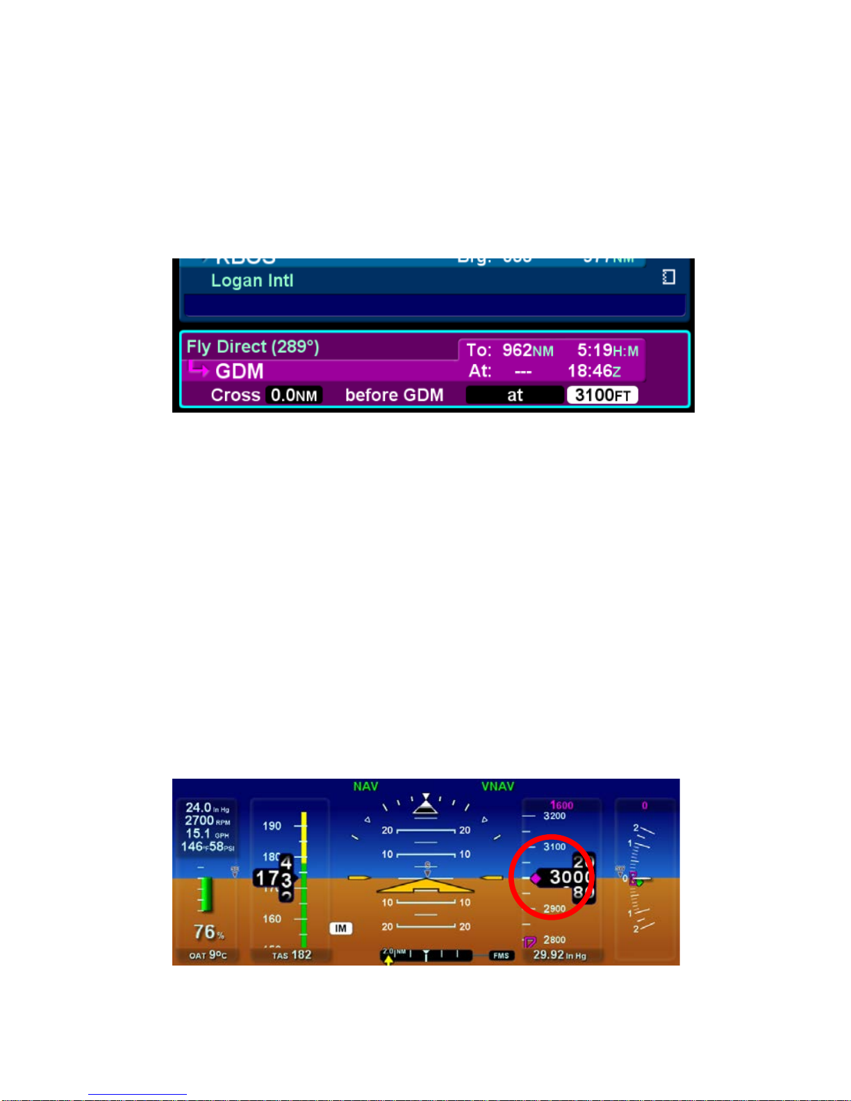
right “at” the constraint. An example of the FMS altitude
constraint field is shown immediately below.
VNAV will plan and attempt to meet constraints using the
preferred climb/descent rate, but will adjust as necessary up to
the maximum rate. The default descent/climb rate for all VNAV
operations is 500 fpm. If a different default rate is desired, the
FMS Setup pages can be used to set a new value (up to 1500
fpm) but this is not recommended by Avidyne. Maximum rates
may also be modified, but you should always be sure to leave at
least a 250 FPM difference from the preferred rate so that VNAV
has a margin for control. If the two rates are too close together,
VNAV will have little to no margin and the “VNAV Unable
Constraint” alert will be a frequent occurrence.
The FMS-computed VNAV target altitude is depicted on the
altimeter tape as a magenta diamond as shown in the image
below. The green VSR diamond on the VSI scale is advisory only.
Page 39

Climb-out/Enroute 3-9
Whenever VNAV is selected and the aircraft passes the last
waypoint in the flight plan with an altitude constraint, the autopilot
will automatically transition to ALT Hold mode at the last VNAV
waypoint altitude constraint.
If conducting a precision approach in VNAV mode, VNAV will
automatically disengage when the final approach course is
captured. For ILS approaches, the system will almost
simultaneously switch primary nav source so that the aircraft
continues to intercept and follow the glideslope. For precision
WAAS approaches, the system will automatically begin following
the vertical guidance provided by the WAAS approach.
If conducting a non-precision approach in VNAV mode, VNAV will
fly all defined step-down fixes until reaching the leg that contains
the Missed Approach Point, at which time, VNAV will
automatically disengage and the autopilot will transition to Altitude
Hold and hold the altitude of the waypoint just prior to the Missed
Approach Point.
NOTE
VNAV Altitude Constraints on a n Airfield
If a flight plan leg altitude constraint is entered for a
flight plan waypoint that is an airport, the def aul t
VNAV target altitude cons traint will be 100 0’ AGL
and 5 miles prior to the airport. Taking advantage of
this feature can produce a good technique of using
VNAV to enter a VFR pattern including presenting a
Top of Decent marker on the map and a smooth,
controlled entry into the VFR pattern in VNAV mode.
When flying a published missed approach in VNAV mode, all
altitude constraints will be achieved until there are no further
altitude constraints in the procedure. Holding patterns as part of
a published missed approach do not typically have an associated
altitude constraint and, therefore, VNAV will typically
automatically transit io n to Altitude Hold mode upon entering the
hold.
Page 40

3-10 Climb-out/Enroute
If VNAV is engaged when the next altitude constraint in the flight
plan is above the current aircraft altitude, the system will hold the
current aircraft altitude (and not climb to that constraint) and the
IFD will display the cyan advisory message, “VNAV Holding Alt”.
If the system has concluded that it cannot make the next vertical
constraint for any reason, a yellow R6 caution message, “VNAV
Unable Constraint” is issued. In this case, additional pilot input
may be required if the entered vertical constraint is to be met.
If VNAV is terminated for some reason other than an overt pilot
action, a cyan advisory message, “VNAV Terminated” is
displayed. Likewise, whe n ever VN AV is press ed on the autop il ot
control panel but conditions are invalid for VNAV (e.g. Primary
Nav source not FMS, autopilot not in NAV, no down-path altitude
constraints in the flight plan, etc), a cyan advisory message,
“VNAV Unavailable” is displayed.
The autopilot modes annunciator indication is a green “VNAV”.
There is no armed (cyan) VNAV mode.
ALTITUDE CAPTURE MODE
Altitude captures can be performed using IAS, VS, VNAV or
PITCH.
To perform an indicated airspeed-based altitude capture, set both
the IAS bug and the ALT bug to the desired values and press the
“IAS” button on the autopilot control panel. The system has a
Alt-Always-Armed design that means the “ALT” button will
automatically arm after pressing just the “IAS” button. The system
will light the IAS button in green and turn the IAS bug solid and
light the ALT button in cyan and turn the ALT bug solid.
To perform a vertical speed-based altitude capture, set both the
VS bug and the ALT bug to the desired values and press the “VS”
button on the autopilot control panel. The system has a AltAlways-Armed design that means the “ALT” button will
automatically arm after pressing just the “VS” button. The system
will light the VS button in green and turn the VS bug solid and
light the ALT button in cyan and turn the ALT bug solid. A pilot
throttle input may be required to sustain the target vertical speed.
Change 1
Page 41

Climb-out/Enroute 3-11
NOTE
Altitude Capture Needs Achievable Commands
Care should be taken such that a logical set of IAS
(or VS) and ALT targets are selected in order to
capture the desired altitude. For example, if a
negative vertical speed is selected and an altitude
above present aircraft altitude is selected, and then
an Altitude Capture commanded, the autopilot will
attempt to fly at the commanded negative vertical
speed and never cross the targeted altitude, thereby
never transitioning to Altitude Hold mode.
There is also a ‘black out’ period where the autopilot will ignore
the commanded target altitude if it is being edited as the original
target altitude is approache d. For example, if the system is
currently performing an altitude capture on departure leg to an
ATC assigned altitude, and as the aircraft is approaching that
original assigned altitude, ATC issues a new assigned altitude
that the pilot is in the process of entering into the system, the
autopilot will ignore the original target and keep climbing to the
new target. As soon as the edit mode is exited, as indicated by
the altitude bug value no longer being reverse-highlighted, the
autopilot will honor whatev er target altitude is active in the
system.
The autopilot modes annunciator indication for altitude captures
are a green “IAS” or “VS” and a cyan “ALT”. As the target
altitude is approached, the “IAS” or “VS” annunciators and
buttons on the autopilot control panel extinguish and the “ALT”
annunciator and button turns green and flashes for up to 10
seconds indicating the system is capturing the target altitude. At
the end of the flashing period, both the modes annunciator and
the control panel button are displayed in steady green.
Page 42

3-12 Climb-out/Enroute
STRAIGHT AND LEVEL
NOTE
Straight and Level Definition
Pressing the “STRAIGHT AND LEVEL” button on
the autopilot will result in a zero bank, +2° pitch
angle attitude. It is not an altitude hold mode or a
zero vertical speed mode, nor does it hold a
heading.
NOTE
Straight and Level Usable Envelope
The Straight and Level button and functionality were
demonstrated to the POH limits of the aircraft (±60°
bank, ±30° pitch). Straight and Level is not to be
relied upon to stabilize an aircraft under all
conditions. Activating this mode will result in the
autopilot making its best effort to reach a wings
level, +2° pitch angle attitude. Depending on the
power setting and aircraft configuration, this could
produce a climb, steady altitude, or a descent
Straight and Level mode is entered by pressing the “STRAIGHT
& LEVEL” button on the autopilot control panel. The system will
light the control panel button in green (blinking) and immediately
change the bank and pitch as required to seek wings level, +2°
pitch angle conditions. Once straight and level is achieved, the
Straight & Level button on the control panel will be steady green
until another mode is selected. Upset recovery will be a smooth,
but depending on the entry attitude, aggressive maneuver
designed to achieve those steady state conditions in an expedited
manner. At sufficiently high power settings and aircraft
configurations (e.g. no flaps), a +2° p itc h angl e will res ult in a
shallow climb. At low power settings and/or aircraft
configurations, a +2° pitch angle may result in a descent.
Page 43

Climb-out/Enroute 3-13
Straight and Level mode can be entered from any autopilot state,
including from the off position.
NOTE
Limitation of Overspeed Protection in Straight
and Level
Overspeed protection is not ensured during initiation
of Straight and Level mode. Depending on the
dynamics of the airplane and the available torque in
the servos, the recovery to straight and level
conditions may exceed Vne. For example, if the
aircraft were in an extreme nose-low and/or highspeed condition at time of Straight and Level
activation, it is possible for Vne to be exceeded
during the recovery to straight and level conditions.
The autopilot modes annunciator indication is a green
“STRAIGHT AND LEVEL”. If the aircraft was not in a wings
level, zero flight path condition at time of mode entry, then both
the button and the mode annunciator will flash green while the
aircraft is being maneuvered to achieve those conditions. At that
time, both the control panel button and the mode annunciator
stop flashing and turn steady green.
PILOT SELECTABLE INTERCEPTS
The autopilot can be commanded to perform a pilot selectable
intercept angle in the lateral modes of NAV. This can prove
useful both enroute as well as in the terminal area and
approaches.
To perform a pilot selectable intercept of a calculated nav course,
set the heading bug to the desired value and press the “HDG”
button on the autopilot control panel. If the Primary Nav LSK was
set to FMS, the system will light the HDG button in green and tur n
the heading bug solid and light the NAV button in cyan. If the
Primary Nav LSK was set to NAV1 or NAV2, then make a
Page 44

3-14 Climb-out/Enroute
simultaneous push of both the heading (HDG) and lateral nav
(NAV) buttons on the autopilot control panel.
The heading knob can be adjusted at any time (before or after
entering pilot selectable intercept mode) and the system will
adjust the intercept angle accordingly.
To disarm the intercept of the selected Nav source, press the
“HDG” button. To re-arm the intercept, press “NAV” again.
The autopilot modes annunciator indication for pilot selectable
intercepts are a green “HDG” and a cyan “NAV”. As the lateral
nav course is approached, the “HDG” annunciators and buttons
on the autopilot control panel extinguish and the “NAV”
annunciators and button turns green and flashes for up to 10
seconds indicating the system is capturing the lateral nav course.
At the end of the flashing period, both the modes annunciator and
the control panel button are displayed in steady green.
CONTROL WHEEL STEERING MODE
Control Wheel Steering (CWS) mode is entered by pressing the
CWS button on the aircraft yoke in those aircraft that support this
functionality.
CWS mode allows the servos to be temporarily disengaged for
the duration that the CWS button is held down, providing an
opportunity for the pilot to manually maneuver the aircraft as
desired without disconnecting the autopilot. Typical uses for this
mode include an easy way to adjust the pitch and bank targets
while in PITCH and/or BANK hold modes, maneuvering to avoid
traffic, weather, or airspace conflicts, flying a more aggressive
intercept scenario than the autopilot would have provided, and an
alternative method of syncing the active vertical mode bugs (ALT,
IAS, or VS) to present aircraft state.
The flight director command bars will be removed from display for
the duration that the CWS mode is active.
During CWS, the horizontal targets (HDG or CRS) remain
unchanged and if either HDG or NAV modes were active
immediately prior to engaging CWS, the autopilot will
automatically re-establish its tracking of those modes and targets
when the CWS button is no longer depressed. If one of the
Change 1
Page 45

Climb-out/Enroute 3-15
commandable vertical modes (ALT, IAS, or VS) were active
immediately prior to engaging CWS, the bug associated with the
active mode (e.g. altitude bug for ALT mode, IAS bug for IAS
mode, and VS bug for VS mode) will stay synchronized with the
actual aircraft state and when the CWS button is no longer
depressed, the new bug value becomes the new target.
If PITCH and/or BANK modes were active at the time of CWS
engagement, the pitch and bank values at the time of CWS
button release will become the new pitch and bank values the
autopilot will hold.
The autopilot modes annunciator indication is white “CWS”. The
autopilot modes annunciators that were lit immediately prior to
entering CWS remain lit in the same manner and the “CWS”
annunciation takes the place of the “AP”, “FD”, or “AP READY”
annunciation locati on whi le it is active.
TAKE OFF/GO AROUND (TO/GA) MODE
TO/GA mode is entered by pressing the TO/GA button on or near
the aircraft throttle(s) in those aircraft that support this
functionality.
The system uses the current autopilot state to determine if TakeOff (TO) or Go-Around (GA) behavior is desired.
If the autopilot was not engaged in any mode (“AP READY”
displayed in the autopilot modes annunciators strip), then
activating the TO/GA control will put the autopilot into Flight
Director (“FD”), Pitch (“PITCH”), and Roll (“ROLL”) modes. In
this case, the system will provide flight director command bars,
that if followed, result in a fixed pitch that results in climb under
full power for the aircraft type and zero roll. That pitch value
varies with aircraft type but ranges from 5 deg (e.g. most single
engine piston aircraft) to 8 deg (e.g. most turbine aircraft).
Once safely away from the ground, the expectation is that the
pilot will then adjus t the autopilot targets and modes as desired.
If the autopilot had been in any mode other than AP READY at
the time of TO/GA control activation, it is assumed that GoAround behavior is desired as described in Section 4 of this
guide.
Change 1
Page 46

Page 47

Approach Procedures 3-1
4 Approach Procedures ......................................................4-2
GENERAL BEHAVIOR .................................................................4-2
APPROACH MODES ...................................................................4-2
WAAS Approaches ............................................................................... 4-2
Non-WAAS GPS approach (RNAV or Overlay or LNAV) ....................... 4-5
VOR approach ...................................................................................... 4-5
Localizer approach ................................................................................ 4-6
ILS approach including glide slope intercept ......................................... 4-7
Procedure Turn ILS or Localizers .......................................................... 4-8
Back course approaches ....................................................................... 4-9
Missed Approach ................................................................................ 4-10
Take off/Go Around (TO/GA) Mode ..................................................... 4-11
Change 1
4-1
Page 48

4-2 Approach Procedures
4 Approach Procedures
GENERAL BEHAVIOR
The integrated DFC100 and IFD system is designed to take full
advantage of the auto transition capability of the FMS900w for
flying a GPS flight plan ending in a GPS or ILS approach. As
long as the desired approach has been selected in the FMS900w
and is part of the active flight plan, courses will be automatically
loaded and many mode transitions will be automatic resulting in a
hands-free transition.
If the approach was not part of the active FMS flight plan, or
NAV1/2 was manually selected in the PFD Pri Nav field, it is
required that the inbound course be set using the PFD course set
knob for accurate localizer intercept and tr acking.
Note that “GS” mode as annunciated refers to a generic
glideslope, encompassing both ILS glideslope and GPS WAAS
approach vertical guidance.
APPROACH MODES
LPV (RNAV) approaches are the preferred approach for the
combined IFD-DFC100 system, if available.
WAAS APPROACHES
When “FMS” has been selected as the source in the “Primary
Nav” LSK, and one of the RNAV/GPS approach types with
vertical guidance (LPV, L/VNAV, LNAV+V) is selected in the
FMS, the ADI will provide horizonta l and vert ic al gu idanc e b y
means of the CDI, HDI and VDI.
WAAS approaches must be flown with the DFC100 system in
NAV APPR mode and the “Primary Nav” LSK set to FMS. For a
full approach, the autopilot will remain in NAV throughout the
approach. For a vectors-to-final approach, the autopilot will be in
HDG with NAV armed until the final approach course is captured,
and then it will switch automatically to NAV. For those WAAS
approaches that have a vertical guidance component, once the
aircraft is on final, the GS mode will also engage.
Change 1
Page 49

Approach Procedures 4-3
There are several types of WAAS approaches. The FMS will
automatically select the best available approach based on current
GPS integrity and will indicate the selection as the HDI source.
The pilot must monitor the HDI source throughout the approach
and use charted minimums appropriate to the approach type. If
an approach type is not indicated by the time the final approach
fix (FAF) is reached and the HDI source is given as FMS, do not
descend – the conditions required to fly the approach have not
been met and you must fly the missed approach procedure.
WAAS approach types that may be indicated as the HDI source
include:
• LNAV (Lateral Navigation)
Provides lateral (horizontal) guidance only, with standard
GPS precision of 0.3 NM full-scale deflection. This is
essentially the same as a non-WAAS GPS approach. It is
flown as any other non-prec ision appro ac h – observing
step down restrictions, descend to MDA, fly at MDA
altitude to the MAP, and execute the missed approach
procedure if appropriate. Since there is no vertical
guidance associated with this type of approach, the VDI
is not displayed.
• LNAV+V (Lateral Navigation with Vertical Information)
This mode provides the same lateral navigation as LNAV,
but presents an ILS GS-like presentation on the VDI. The
GPS draws a 3-D picture of the approach based on
crossing the FAF at the depicted altitude. Then it follows
a glidepath from the published approach, which is
typically a 3 degree angle to the touchdown zone. This
type of approach remains a non-precision approach and
does not consider any step-do wn lim itati ons.
For this approach type, manual coupling to the autopilot
is permitted. After “LNAV+V” is annunciated as the HDI
source but prior to FAF, the NAV (or APPR) button on the
autopilot must be pressed. GS will arm or engage
depending on your position relative to the glide slope. Fly
coupled to the MDA, observing any step down restrictions
as needed. If a level off at the MDA is desired, the ALT
button must be pressed on the autopilot.
Page 50

4-4 Approach Procedures
• LNAV/VNAV (Lateral Navigation with Vertical
Navigation) In this mode, the GPS provides lateral
navigation, providing more accurate guidance than
regular LNAV but easier to follow indications than a
localizer. The vertical navigation is driven by GPS
signals. LNAV/VNAV approaches are operationally
different from LNAV+V in that the glide path is protected
from obstructions but attention still must be applied to
step down fixes. Also, the minimum altitude presented is
a decision altitude/height (DA/DH) – DA being what is on
the altimeter, and DH being the height of the DA above
the touchdown zone elevation. This is not a MDA, thus,
fly it just as though it were an ILS approach: follow the
glide slope all the way to the DA before initiating a
missed approach, if appropriate.
This type of approach is automatically coupled to the
autopilot, meaning that somewhere in the vicinity of the
FAF, with “L/VNAV” annunciated as the HDI source, the
FMS will automatically toggle the autopilot mode to NAV
APPR and GS will either arm or engage depending on
your position relative to the glide path .
LPV (Localizer Precision with Ver tical Guidance)
(FMS900w only) The lateral guidance is significantly
more precise than LNAV, and equivalent to that of a
localizer, except easier to fly. Vertical guidance is
provided to minimums as low as 200’ AGL above the
touchdown zone. Lateral tolerance starts out at 0.3 NM
full-scale (slightly tighter than a localizer at the FAF),
transitioning to 350 feet either side at the runway
threshold (slightly looser than a localizer). The steering
remains linear all the way so you don’t get the difficult to
follow swings of a VHF localizer close to the runway. The
vertical guidance is precise and has a DA/DH (shown as
“DA(H)” on approach charts) rather than a MDA.
This type of approach is also automatically coupled to
your autopilot. In the vicinity of the FAF, with “LPV”
annunciated at the HDI source, the FMS will
Page 51

Approach Procedures 4-5
automatically toggle the autopilot mode to NAV APPR
and GS will either arm or engage depending on your
position relative to the glide path.
If the FMS has determined that satellite coverage is insufficient
for use of GPS as the primary navigation source, a Caution is
provided. This may occur at any time during the approach and
requires that you execute a missed approach.
NON-WAAS GPS APPROACH (RNAV OR OVERLAY OR LNAV)
□ Ensure the Primary Nav LSK is set to FMS as the source
and a GPS or RNAV approach is loaded in the FMS900w
□ Press the “NAV” or “APPR” buttons on the autopilot
control panel
□ Note that the “NAV” and “APPR” buttons on the autopilot
control panel are lit in green
□ Note that “NAV APPR” is displayed in the PFD mode
annunciator section
□ Execute a missed approach, if appropriate
VOR APPROACH
□ Ensure the Primary Nav LSK is set to a VHF source
(NAV1 or NAV2) and tuned to a VOR and the VOR
approach is loaded in the FMS900 w
□ Ensure the approach course is set in the Selected
Course window
□ Press “APPR” on the autopilot control panel, or “NAV”
and then “APPR” (VOR approaches are the only types of
approaches in which the “APPR” button must be
pressed.)
□ Note that both the “NAV” and “APPR” button on the
autopilot control panel are lit in green
□ Note that “VOR APPR” is displayed in the PFD mode
annunciator section
□ Execute a missed approach, if appropriate
Change 1
Page 52

4-6 Approach Procedures
LOCALIZER AP PROACH
If flying a Vectors-To-Final approach, use 1 of 2 techniques:
1. Use the Vectors-To-Final selection in the FMS400/90 0 w
drop down windows to select that type of transition to the
localizer final and the “HDG” button on the autopilot
control panel and control the aircraft vector via the
Heading knob on the keyboard. (Avidyne
Recommended Technique);
2. Use the Heading knob on the keyboard and the “HDG”
button on the autopilot control panel when ATC is issuing
vectors.
NAV APPR can be armed prior to capturing the localizer beam
but it is highly recommended to wait until ATC clears you for the
approach before trying to arm NAV and APPR. To arm NAV
APPR while still in Heading/Vectors mode, press the “NAV” (or
“APPR”) button. Once armed, the system will automatically
capture the localizer signal and transition out of Heading/Vectors
mode on its own.
□ Ensure the Primary Nav LSK is set to a VHF source
(NAV1 or NAV2) and tuned to a localizer and the loca li zer
approach is loaded in the FMS900 w
□ Ensure the front course is set in the Selected Course
window
□ When cleared for the approach or established on final,
press the “NAV” or “APPR” buttons on the autopilot
control panel (either will wo rk )
□ Note that the “NAV” and “APPR” buttons on the autopilot
control panel are lit in cyan
□ Execute the approach by commanding heading until the
localizer is captured
□ Note that “NAV APPR” is now displayed in green in the
PFD mode annunciator section
□ If desired, VS mode can be used to control the vertical
axis
□ Execute a missed approach, if appropriate
Page 53

Approach Procedures 4-7
ILS APPROACH INCLUDING GLIDE SLOPE INTERCEPT
When flying a Vectors-To-Final approach, use 1 of 2 techniques:
1. Use the Vectors-To-Final selection in the FMS900w drop
down windows to select that type of transition to the
localizer final and the “HDG” button on the autopilot
control panel and control the aircraft vector via the
Heading knob on the keyboard. (Avidyne
Recommended Technique);
2. Use the Heading knob on the keyboard and the “HDG”
button on the autopilot control panel when ATC is issuing
vectors.
NAV APPR can be armed prior to capturing the localizer beam
but it is highly recommended to wait until ATC clears you for the
approach before arming NAV and APPR. To arm NAV APPR
while still in Heading/Vectors mode, press the “NAV” (or “APPR”)
button. Once armed, the system will automatically capture the
localizer signal and transition out of Heading mode on its own.
□ Ensure the Primary Nav LSK is set to a VHF source
(NAV1 or NAV2) and tuned to a properly identified ILS
and the ILS is loaded in the FMS900w
□ Press “NAV” or “APPR” on the autopilot control panel
(Approach mode will automatically arm if tuned to an ILS
frequency)
□ The autopilot will enter NAV and Approach lateral modes
or arms them if off course
□ The autopilot will automatically arm the GS vertical mode,
retaining the existing vertical mode until capture
□ At this point, “NAV” and “APPR” buttons along with the
previous vertical buttons will be lit green on the autopilot
control panel and the “GS” button will be lit in cyan
□ PFD mode annunciator will display NAV and APPR along
with the previous vertica l mode in green and GS in cyan
□ When the autopilot captures glideslope, the vertical mode
button on the autopilot control panel and mode
annunciator on the PFD will transition to a flashing green
Page 54

4-8 Approach Procedures
“GS” which will flash for approximately 10 seconds before
going steady green
□ Execute a missed approach, if appropriate
Glide slope is intended to be captured from below. If so desired,
or required via NOTAM, GS mode can be toggled on/off through
presses of the “GS” button on the autopilot control panel. There
is no other required
time to press the “GS” button.
In the event the pilot is attempting to capture the glide slope from
above, glide slope will be captured as the aircraft passes through
the glide slope signal, if GS mode was previously armed. If GS
hadn’t been armed, glide slope will be captured by manually
pressing the “GS” button on the autopilot control panel when
within 1 dot of glide slope centerline.
PROCEDURE TURN ILS OR LOCALIZERS
The procedure for an ILS or Localizer with a procedure turn in a
combined DFC100/FMS900w system results in the aircraft
automatically flying the outbound procedure turn heading,
automatically making the turn inbound to the inbound procedure
turn heading, then automatically capturing and flying the final
approach course.
To fly the full published procedure turn, ensure the approach is
loaded and activated in the FMS and ensure the Primary Nav
LSK is set to FMS. In this case, the DFC100 should be in NAV
and VNAV modes (other vertical modes are permitted) and the
GS should be automatically armed in blue as soon as the VHF
signal is received. Once established inbound and within glide
slope capture criteria, the previously engaged vertical mode will
automatically transition to GS. In any case, the vertical mode of
the autopilot won’t automatically change until the system
recognizes it is on final.
Page 55

Approach Procedures 4-9
BACK COURSE APPROACHES
Always ensure the front course is set in the Selected Course
window. The system will recognize it is on a back course when
the VHF receiver is locked onto a valid signal and there is a
sufficient difference between aircraft heading and the selected
course. There is no need or ability to manually select back
course operations with the DFC100. A “BCRS” annunciation will
be added to the HDI, the HDI and CDI indicators will display
correct sensing, and the autopi lot will turn in the proper direction.
□ Ensure the Primary Nav LSK is set to a VHF source
(NAV1 or NAV2) and tuned to a LOC/ILS and the
approach is loaded in the FMS900 w
□ Ensure the front course is set in the Selected Course
window (if the backcourse approach is loa ded in the
FMS, then the course is automatically loaded in the
Primary Nav LSK datablock.)
□ Press either the “NAV” or “APPR” button on the autopilot
control panel (either will wo rk fine)
□ Note that the “NAV” and “APPR” button are lit in green on
the autopilot control panel
□ Note that “NAV APPR” is displayed in green in the
autopilot modes annunciator section of the display
Page 56

4-10 Approach Procedures
MISSED APPROACH
Prior to going missed approach, apply go-around power, ensure
the aircraft is trimmed for the power setting, establish a climb
attitude and use the autopilot to smoothly execute the assigned
climb-out or published missed approach procedures.
To fly a coupled missed approach:
ATC assigned climb-out
A recommended technique for executing the as sign ed c lim b-out
instructions is as follows:
□ Set the altitude bug to the assigned climb-out altitude,
ideally prior to passing the FAF
□ Set the VS bug to the desired climb speed or rate, ideally
prior to passing the FAF
□ Set the heading bug to the ATC assigned heading
□ At the point when you decide to go missed, add power as
required
□ Press the “HDG” or “NAV” button on the autopilot control
head, depending on missed approach instructions
□ Press the “VS” buttons on the autopilot control head to
command an altitude capture at the desired VS
Published Missed Appr oac h
A recommended technique for executing the published missed
approach procedures is as follows:
□ Ensure the published missed approach is part of the
active FMS flight plan
□ Press “Enable Published Missed” L5 LSK when departi ng
FAF
□ At the point when you decide to go missed, add power as
required
Page 57

Approach Procedures 4-11
□ After the aircraft is cleaned up, go-around power applied
and climb-out attitude established, press the “Enable
Published Missed” L5 LSK on the PFD page if not
already pressed
□ Press the “NAV” button and the “VNAV” button on the
autopilot control head after cros s ing the MAP.
NOTE
Using VNAV to fly a Coupled Missed Approach
Using VNAV to fly a coupled published missed
approach is a highly recommended technique
because it automatically fills in all autopilot lateral
and vertical targets and even protects against
insufficient climb power via Envelope Protection.
However, do NOT press the VNAV button prior to
reaching the Missed Approach Point (MAP).
TAKE OFF/GO AROUND (TO/GA) MODE
TO/GA mode is entered by pressing the TO/GA button on or near
the aircraft throttle(s) in those aircraft that support this
functionality.
The system uses the current autopilot state to determine if TakeOff (TO) or Go-Around (GA) behavior is desired.
If the autopilot had been in any mode other than AP READY at
the time of TO/GA control activation, it is assumed that GA
behavior is desired
In GA, the system will initially seek a fixed pitch that results in
climb under full power for the aircraft type and zero roll. That
pitch value varies with aircraft type but ranges from 5 deg (e.g.
most single engine piston aircraft) to 8 deg (e.g. most turbine
aircraft). Once the initial fixed pitch and zero roll have been
achieved, follow-on navigation and autopilot performance will take
over as described below.
Change 1
Page 58

4-12 Approach Procedures
There is a distinction between whether a missed approach has
been enabled or not, and, what type of missed approach is called
for by the pilot – Published Missed Approach or Assigned Missed
Approach. Enabling the missed approach, and selecting
Published vs. Assigned is done via the L5 Line Select Key on a
PFD-configured Integrated Flight Display.
On final approach, pressing TO/GA causes the autopilot to:
• Activate PITCH mode and pitch aircraft up
• Arm ALT mode
• Disarm all lateral modes and activate ROLL mode, wings
level, if no missed approach is enabled
• Remain in NAV mode, if a missed approach is enabled
• Arm HDG mode, if an assigned missed approach is
enabled
• Arm VNAV mode, if a published missed approach is
enabled
At the Missed Approach Point (MAP), the following additional
actions are automatical l y perf ormed:
• All armed (cyan) autopilot modes transition to engaged
(green)
• Primary Nav source selection on the IFD automatically
switches to FMS
In summary, the system will immediately initiate a pitch up, and
assuming sufficient power/energy, a climb but, aside from the
FMS monitoring progress toward the MAP, no latera l action will
take place until passing the MAP.
If TO/GA is activated at any time other than take-off or on an
approach, the system will still activate PITCH mode, pitch up and
arm ALT mode in the vertical axis and disarm any lateral axis
mode and activate ROLL mode.
Change 1
Page 59

Abnormal Procedures 5-1
5 Abnormal Procedures ......................................................5-2
GENERAL FAILURE MODE INFORMATION ...............................5-2
OTHER ERROR MODES .............................................................5-5
ALERTS ........................................................................................5-7
LOSS OF ENGINE .....................................................................5-10
Page 60

5-2 Abnormal Procedures
5 Abnormal Procedures
GENERAL FAILURE MODE INFORMATION
The only failure modes that result in the loss of a DFC-series
autopilot are when all of the system AHRS are unavailable (RedXs over the attitude display), the autopilot has completely failed or
lost power, or when a ll of the IFDs have no power.
Each autopilot contains an internal data recorder for use during
service operations. The contents of the data logs remain the
property of Avidyne. If an anomalous behavior is observed with
the autopilot, pressing the “GS” button on the autopilot control
panel multiple times will produce a series of events in the data log
that will aid the Avidyne Service Cent er in finding and ana l yzing
the data logs during troubleshooting operations.
Some failure modes identified in this section do not affect the
functioning of the AHRS and therefore allow continued use of the
autopilot.
In all cases, basic airmanship should be exercised and
fundamentals utilized such as maintain aircraft control, analyze
the situation, and take proper action.
Refer to the Release 9.2 or later IFD Pilot Guide for more detail
on the IFD-related system malfunctions.
The following failure modes result in no DFC100 autopilot
functionality:
o Loss of all on-board AHR S
o Loss of power to all on-board IFDs
o Loss of autopilot power
o Complete loss of system-wide Databus
o Failure of all installed AHRS to align initially
Change 1
Page 61

Abnormal Procedures 5-3
The following failure modes result in some degradation of the
DFC100 autopilot functionality as noted:
o Loss of all on-board air data systems (results in the
inability to use any of the air data modes such as VS,
IAS, ALT modes, and loss of Envelope Protection and
Full-time Envelope Alerting functions - note that Straight
and Level, Pitch, Roll, and ILS capabilities are retained
and the VS knob can be used to adjust pitch)
o Ice in the pitot-static lines (results in inability to track or
track accurately any IAS, VS, or ALT related mode)
o Inoperative Mx and Safety Recorder (results in loss of all
aural alerting and autopilot dis conn ect tones)
o Servo Failure (depending on the servo lost, potential
inability of the airplane to achieve set targets)
o Servo Limit reached (results in the inability of the
autopilot to track the commanded targets)
o Loss of Keyboard (forces the use of the B ug Se lect tab of
the PFD page to set Heading and Altitude bug tar ge ts )
o Loss of both VHF radios (results in the inability to select
and track any VHF-based target such as Localizer, ILS or
VOR)
o Loss of both GPS (results in inability to use FMS as the
source in Primary Nav LSK and therefore, no Vectors)
o Crosscheck Attitude 1 (in single AHRS-equipped aircraft,
this specific Crosscheck Attitude message will result in an
autopilot disconnect and “Gyro Miscompare” aural alert
but it will allow a manual autopilot reengagement)
o Gyro miscompare in the air (results in a disconnect of the
autopilot in dual AHRS equipped systems after a pitch or
roll miscompare and after any subsequent manual
reengagement, loss of comparator)
Change 1
Page 62

5-4 Abnormal Procedures
The following failure modes have no effect on DF C1 00 auto pi lot
functionality:
o Loss of turn coordinator (in dual AHRS systems)
o Loss of a single IFD (in dual AHRS systems with 1-2
switch set to Auto or the failed IFD did not house the
AHRS)
o Loss of a single AHRS (in dual AHRS systems wit h 1 -2
switch set to Auto)
o Loss of a single VHF radio
o Loss of a single GPS
o Loss of LCD display(s)
Page 63

Abnormal Procedures 5-5
OTHER E RRO R MOD ES
Autopilot failures that prevent any operation are annunciated
across the center of the PFD mode annunciator strip in amber
(yellow) as shown in the example immediately below.
IFD Autopilot Annunciator
AUTOPILOT INOP
The autopilot is unusable but the
system cannot determine why.
Recommend immediate transition to
hand-flying and if no automatic restart
has been initiated, consider cycling the
autopilot circuit breaker one time.
AUTOPILOT INOP
AHRS
COMPARATOR FAIL
Dual AHRS system: The system has
concluded that one of the AHRS is
unavailable (not failed and not aligning).
Single AHRS system: The system has
concluded that the turn coordinator has
failed or is not available.
AUTOPILOT INOP
SELF TEST FAIL
The autopilot failed its power-up selftest. If the fault does not clear itself
within 15 seconds, consider cycling
power to the autopilot via the circuit
breaker or avionics master.
AUTOPILOT INOP
AHRS FAIL
All on-board AHRS have failed,
rendering the autopilot non-functional.
Change 1
Page 64

5-6 Abnormal Procedures
AUTOPILOT INOP
AHR S ALIGNI N G
If any of the on-board AHRS have not
yet completed alignment, this message
will be displayed. This message should
be expected to be seen during all
normal ground operations in the course
of all standard alignments.
AUTOPILOT
DISCONNECTED
Displayed anytime the autopilot has
been manually or automatically
disconnected and shou ld b e
accompanied by 16 beeps.
NO
COMMUNICATION
WITH AUTOPILOT
Indicates the IFDs have stopped
receiving data from the autopilot
resulting in the loss of all autopilot
functionality for the duration of the
message. It is possible that the autopilot
will conduct an auto-reset and if
successful, all functionality would be
restored and a manual re-command of
the autopilot modes will be available. If
an auto-reset is not conducted, consider
cycling power to the autopilot via the
circuit breaker or avionics master.
Change 1
Page 65
Abnormal Procedures 5-7
ALERTS
In addition to system failures as noted above, there are several
alerts that may affect DFC autopilot and subsequent pilot
operations. The following list generates a yellow caution lamp and
associated R6 LSK messages:
AHRS Miscompare Dual AHRS system: The system has
detected a roll
or pitch miscompare
between the two AHRS. The autopilot will
disconnect upon initiation of this
miscompare alert and will generate a
“GYRO MISCOMPARE” aural alert.
Single AHRS system: The system has
detected a roll miscompare between the
AHRS and the turn coordinator. The
autopilot will not
disconnect upon initiation
of this miscompare alert but will generate
a “GYRO MISCOMPARE” aural alert.
In either case, evaluate the accuracy of
the IFD AHRS solution by comparing the
PFD display to the backup gauges, and if
in VMC conditions, the out-the-window
view. If it can be concluded that the PFD
is accurate, consider re-engag ing the
autopilot, as required and continue
standard autopilot operations but be
vigilant knowing that the AHRS-AHRS or
AHRS-TC comparator has noted a sensor
miscompare.
AP Audio Unavail
The autopilot aural alerts are unavailable.
Apply extra vigilance to the auto pilot
annunciator status messages along the
top of the PFD due to the absence of the
associated aural alerts. After the flight,
notify an Avidyne Service Center or
Avidyne Customer Support for a repair
action.
Change 1
Page 66

5-8 Abnormal Procedures
The following list generates a cyan L6 LSK advisory message:
Trimming Up
Trimming Down
The system has recognized that trim has
been running for an excessive duration.
In all cases, trim can be manually
overridden with pilot-controlled control
stick/yoke inputs. If the alert is present for
more than a few seconds, consider
disconnecting the autopilot, manually trim
the aircraft accordingly, and if autopilot
operations are still desired, re-engage the
autopilot in the desired mode.
AP/Nav Invalid
The system has recognized that the VHF
lateral nav signal is invalid. A Red-X will
cover the Horizontal Deviation Indicator
(HDI) on the ADI and the autopilot will
command a wind-corrected course hold
and, if sufficient power is available, the
flight path angle at the time the system
displayed the L6 Advisory message.
Consider switching the nav source in the
PFD page Primary Nav selection. If
unable to reacquire the nav signal, take
the proper action when a navigation
source has been lost. If on a published
approach that requires VHF-based lateral
guidance, the approach must be
terminated.
AP/GS Invalid
The system has recognized that the
vertical nav signal is invalid. A Red-X will
cover the Vertical Deviation Indicator
(VDI) on the ADI and the autopilot will
coast for 5 seconds and, if at the end of
that 5 second period, the signal has not
been reacquired, the autopilot will
transition to Alt Hold mode with al l the
associated mode change indications.
Consider switching the nav source in the
PFD page Primary Nav selection. If
unable to reacquire the vertical nav (more)
Page 67

Abnormal Procedures 5-9
signal, take the proper action when a
navigation source has been lost. If on a
published ILS approach, transition to nonprecision approach procedures and
minimums or go missed approach.
AP AHRS Comp
Unavail
If at any time after an initial AP READY
condition has been achieved, one of the
attitude comparator sources becomes
unavailable, this message is presented.
No disconnect will hap pen and the
autopilot will “fly-through” this event
unaffected.
AP/IFD Comm Fault
If the DFC is unable to recognize the
message data from both IFDs (e.g. a
software mismatch has occurred between
the autopilot and all IFDs), then some
autopilot modes will become unavailable.
In this event, Pitch Hold, Roll Hold, Alt
Hold and Straight and Level modes are
still fully functional. Consider cycling
power to the IFDs and autopilot and if that
does not clear the condition, contact
Avidyne Customer Support.
AP MSR Failure
The system is unable to write and access
data to/from the autopilot maintenance
and safety data recorder. The autopilot
will still be fully functional in all pilotusable modes but the on-board data
logging has likely stopped and all
autopilot aural alerts will be unavailable
Apply extra vigilance to the auto pilot
annunciator status messages along the
top of the PFD due to the absence of the
associated aural alerts. After the flight,
notify an Avidyne Service Center or
Avidyne Customer Support to coordinate
for a repair action.
Page 68

5-10 Abnormal Procedures
VNAV Unable
Constraint
The system has determined that it can not
make the next vertical constraint. It may
be too close or require too much of a
climb or descent rate. Additional pilot
input may be required.
VNAV Unavailable
Message displayed when the VNAV
button on the autopilot has been pressed
but the system is not able to provide
VNAV because either Primary Nav is not
set to FMS, the autopilot is not in NAV
mode (engaged or armed), or there is no
down-path altitude constraint in the flight
plan.
VNAV Terminated
The system has transitioned out of VNAV
mode. This may be a normal operation
during VNAV descents to instrument
finals. The autopilot will typically
transition to ALT Hold in this case.
LOSS OF ENGI NE
Loss of engine does not affect the DFC100 operation but the
DFC100 autopilot can be useful during loss of engine situations.
One technique is to set the IAS bug to best glide speed and
engage IAS mode in the event of engine-out conditions. The
autopilot will adjust aircraft pitch as required to slow down, or
speed up to achieve V
g
, freeing up time to perform other cockpit
duties during this emergency situation.
One minor variation of this technique is to set the IAS bug to V
g
after climb-out so that it is already preset to V
g
.
In either technique, it is recommended to press the “IAS” button
on the autopilot control panel a second time to prevent an
inadvertent altitude capture.
Envelope Protection will prevent the autopilot from stalling the
aircraft during power-off operations.
Page 69

Limitations and Performance 6-1
6 Limitations and Performance ..........................................6-2
LIMITATIONS ...............................................................................6-2
SOFTWARE COMPATIBILTY AND NOTES..……………………...6-4
GENERAL PERFORMANCE – CIRRUS AIRCRAFT ...................6-5
PERFORMANCE IN PITCH TRIM-ONLY AIRCRAFT ..................6-6
PERFORMANCE IN NON-CIRRUS AIRCRAFT...........................6-6
Change 1
Page 70

Page 71

Limitations and Performance 6-2
6 Limitat i ons and Performance
LIMITATIONS
1. For non-FI KI approved air craft: the DFC100 m ust not be
used during icing conditions;
For FIKI approved aircraft: the DFC100 must not be
used during severe icing conditions. Note that in icing
conditions, periodic autopilot disconnect is
recommended to allo w control movement check s. High
forces to move airplane controls are an indication of
severe icing and the autopilot should remain
disconnected until exiting severe icing conditions.
Indications of severe icing include:
a. Indications of frequent autopilot re-trimming
during straight and level flight;
b. Unusually extensive accumulation of ice on the
windshield in areas not normally observed to
collect ice;
c. Acc umulation of ice on th e upper surface of th e
wing aft of the protected area;
d. Accumulation of ice on the engine cowling
and/or spinner further aft than normally
observed;
2. Unusual control force or control deflection, or unusually
large control forces to move flight controls when the
autopilot is disconnected.
3. The DFC100 minimum use height is 200ft AGL. This
means the autopilot m ust be disengaged for takeoff and
landing and disengaged for missed approach or go
around until climb and configuration are established
above 200ft AGL.
4. DFC100 operations are prohibited in aircraft equipped
with pitch trim-only when flaps are deployed more than
50% (no dedicated pitch servo).
Change 1
Page 72

6-3 Limitations and Performance
5. Maximum flap retraction speed (50% to full retracted)
with autopilot engaged is 110 KIAS in aircraft equipped
with pitch trim-only.
6. DFC100 operation is prohibited above:
a. SR2X - 185 KIAS
b. PA46-350 – 180 KIAS
c. PA32 – 180 KIAS
7. The Avidyne DFC100 Series of Digital Autopilots Pilot’s
Guide, P/N 600-00270-000, Revision 02, or later
appropriate revis ion, m ust be availab le to the pilot dur ing
all flight operations.
Change 1
Page 73

Limitations and Performance 6-2
SOFTWARE COMPATABILITY AND NOTES
The following table identifies authorized combinations of IFD and
autopilot code and any associated operational notes. For the
purposes of this table, differences noted in the Operational Notes
column are when compared to DFC100 Pilot Guide 600-00270000 Rev 01
.
IFD
Version
AP
Version*
Operational Notes
9.2.3
Or
9.2.4
02 Full functionality per DFC100 Pilot
Guide 600-00270-000 Rev 01 (except
TO/GA which requires IFD 9.3)
9.2.1 02 - No TO/GA mode
- TRIMMING UP/DOWN message is
displayed more frequently
9.2.3
or
9.2.1
01 - Same as above, and:
- No Flap Overspeed alert
- DFC100 will disconnect during any
AHRS-TC Miscompare in single AHRS
equipped aircraft
- Underspeed alerts are not
suppressed in the flare and on rollout
- MSR FAIL means no AP disconnect
tones
* The Autopilot Version number can be obtained from the aircraft
logs or via Mx Mode of the IFD unit. Once in Mx Mode (enter via
the same method by which logs are downloaded or nav
databases uploaded), press the “SYS” page function key,
“System Status” tab, “Info” line select key (LSK R6) set to
“Software” and scroll down the list looking for the entry “AP 563
App” and look for the revision number (e.g. “02”).
Change 1
6-4 Limitations and Performance
Page 74

6-3 Limitations and Performance
Note: All DFC100-equipped Piper aircraft must have IFD Version
9.2.4 or later and
DFC100 Version 2 or later.
Note: All DFC100-equipped Cirrus aircraft must have IFD Version
9.2.1 or later.
Note: IFD Version 9.2.2 was never fielded.
Note: IFD Version 9.2.3 and later must use DFC100 Version 2 or
later.
GENERAL PERFORMANCE – CIRRUS AIRCRAFT
The input forces required for roll-axis control surface actuation
are demonstrably light and it is not difficult to force the servo (roll
trim spring cartridge) to drive to its limit. By design, reaching the
physical limit causes a micro-switch to be tripped which
effectively decouples the autopilot commands from the flight
control surfaces.
Pilot-induced inputs on the system including yoke input, rudder
input, p-factor, fuel imbalance, airspeed and general aircraft trim
alignment can all contribute to this condition.
In the event the DFC system believes the roll-axis servo limit has
been reached, a yellow “SERVO LIMIT” text message is
displayed along the top edge of the PFD pages.
WARNING
Reaching Servo Limits Can Cause
Uncommanded Rolls
If the roll servo limit is reached, the autopilot may
stop following lateral commands. This could appear
to the pilot as an uncommanded roll or a failure to
follow the commanded lateral target.
As a result, it is highly recommended that a pilot avoid making
flight control inputs while in coupled autopilot mode operations
Limitations and Performance 6-5
Change 1
Page 75

Limitations and Performance 6-2
aside from minor rudder input to maintain coordinated flight.
Moderate rudder or any roll input may result in an inability of the
DFC100 autopilot to track the commanded targets.
It is also important to note that in aircraft equipped with only roll
trim motors (no roll servo), the maximum aileron deflection is ½
the total possible aileron throw.
PERFORMANCE I N PITC H TRIM-ONLY AIRCRAFT
As noted earlier, all modes and behaviors described in this
manual work both in aircraft with pitch servos and those without
(pitch trim-only) with the exception of the reaction to manual
electric trim inputs. However, aircraft equipped with pitch trim only
(no pitch servo) should expect a less precise and, depending on
the environmental and aircraft dynamic conditions, a slower
reaction time in the vertical axis when experiencing vertical
turbulence or other inputs like flap deployment/retraction, IAS
mode tracking and unusual attitude recoveries using the Straight
and Level button.
PERFORMANCE I N NO N-CIRRUS AIRCRAFT
It is highly recommended that a pilot avoid making flight control
inputs while in coupled autopilot mode operations aside from
minor rudder input to maintain coordinated flight. Moderate
rudder or any roll input may result in an inability of the DFC100
autopilot to track the commanded targets.
6-6 Limitations and Performance
Change 1
Page 76

Page 77

Index 1
Index
Annunciations
Aural Alerts, 1-5
Mode Annunciator Strip, 1-5
PFD Annunciators, 1-17
Approaches
WAAS, 4-2
GPS, 4-5
VOR, 4-5
Localizer, 4-6
ILS, 4-7
Procedure Turns, 4-8
Back course, 4-9
Missed Approach, 4-10
Autopilot Controls, 1-4
Autopilot Mod es
Pitch mode, 3-2
Roll mode, 3-2
Vectors mode, 3-3
Nav mode, 3-4
Altittude Hold mode, 3-5
IAS Hold mode, 3-5
VS Hold mode, 3-6
Altitude Capture mode, 3-10
VNAV mode, 3-7
Straight and Level mode, 3-12
Pilot-select i ntercept angle, 3-13
Control Wheel Steering, 3-14
Takeoff/Go Around, 3-15, 4-11
Glide slope, 4-7
Brightness C ontrols, 2-2
Comparators, 1-14
Engagement and H old Limits, 1-13
Envelope Alert ing, 1-9
Envelope Protection, 1-8
Failure Modes
Loss of all DFC100 function, 5-2
Degradation of function, 5-3
No effect on function, 5-4
Autopilot failures, 5-5
Alerts, 5-7
Loss of Engine, 5-10
Flight Director, 1-16
General Overview/Topics
Armed vs Engaged, 1-5
Baro adjust, 1-12
Manual Electric Trim, 1-6
Engagement, 1-15
Disengagement, 1-15
General Perfor m ance – Cirrus, 6-2
Performance – Non Cirrus, 6-4
Ground Operations
System Power, 2-2
Self Test, 2-2
Brightness controls, 2-2
Pre-flight checks, 2-3
Before takeoff checks/setup, 2-4
Limitations, 6-2
Miscompares, 1-14, 5-7
Mode Transitiions, 1-6
Performance in pitch trim -only a/c, 6-6
Performance in non-Cirrus aircraft, 6-6
Servo Limit, 6-3
Software Comp atibility Table, 6-4
Change 1
Page 78

Page 79

Website There is a dedicated w ebsite that provides more informat ion on
this product at http://www.dfc100.com
FAQs
http://www.avidyne.com/downloads/products/dfc90/DFC90-
DFC100-FAQs.pdf
Service Hotline A hotline has been established to service
questions or issues regarding Avidyne products. The U.S. Toll
Free number is 1-888-723-7592. International toll free numbers
are listed at
http://www.avidyne.com/contact/intphones.asp
Email Customer/product support issues can be emailed as well
□ Europe –
□ Australia & Asia –
□ Everywhere else should email
When calling or emailing for product-related help, please have the
following information available, if able:
• Customer Name/Account Information
• Aircraft tail number, DFC100 serial number, PFD serial
number and software versions.
• A good description of the problem or question.
WARRANTY: AVIDYNE WARRANTS THE PRODUCT MANUFACTURED BY IT AGAINST
DEFECTS IN MATERIAL AND WORKMANSHIP FOR A PERIOD OF TWENTY-FOUR (24)
MONTHS FROM DELIVERY TO THE INSTALLER. A COMPLETE COPY OF THE
WARRANTY DATA IS ACCESSIBLE VIA THIS WEB ADDRESS:
WWW.AVIDYNE.COM/PRODUCTS/DFC100/INDEX.ASP
SOFTWARE LICENSE: AVIDYNE CORPORATION (“AVIDYNE”) IS WILLING TO LICENSE
THIS SOFTWARE, PILOT’S GUIDE, AND RELATED MATERIALS (THE “SOFTWARE”)
ONLY ON THE CONDITION THAT YOU AGREE TO THE TERMS OF THE PUBLISHED
SOFTWARE LICENSE WHICH CAN BE ACCESSED VIA THIS WEB ADDRESS:
WWW.AVIDYNE.COM/PRODUCTS/DFC100/INDEX.ASP
Page 80

Page 81

AVIDYNE CORPORATION
55 Old Bedford Road
Lincoln MA 01773
P 781 402 7400 | F 781 402 7599
Toll Free 800-AVIDYNE (800 284 3963)
www.avidyne.com
http://www.avidyne.com/products/dfc100/index.asp
P/N 600-00270-000 Rev 02
 Loading...