

Page 1

®
Pro Tools | HD I/O Guide
Page 2

Legal Notices
© 2014 Avid Technology, Inc., (“Avid”), all rights reserved.
This guide may not be duplicated in whole or in part without
the written consent of Avid.
003, 192 Digital I/O, 192 I/O, 96 I/O, 96i I/O, Adrenaline,
AirSpeed, ALEX, Alienbrain, AME, AniMatte, Archive,
Archive II, Assistant Station, AudioPages, AudioStation,
AutoLoop, AutoSync, Avid, Avid Active, Avid Advanced
Response, Avid DNA, Avid DNxcel, Avid DNxHD, Avid DS
Assist Station, Avid Ignite, Avid Liquid, Avid Media Engine,
Avid Media Processor, Avid MEDIArray, Avid Mojo,
Avid Remote Response, Avid Unity, Avid Unity ISIS,
Avid VideoRAID, AvidRAID, AvidShare, AVIDstripe, AVX,
Beat Detective, Beauty Without The Bandwidth,
Beyond Reality, BF Essentials, Bomb Factory, Bruno, C|24,
CaptureManager, ChromaCurve, ChromaWheel,
Cineractive Engine, Cineractive Player, Cineractive Viewer,
Color Conductor, Command|8, Control|24, Cosmonaut Voice,
CountDown, d2, d3, DAE, D-Command, D-Control, Deko,
DekoCast, D-Fi, D-fx, Digi 002, Digi 003, DigiBase,
Digidesign, Digidesign Audio Engine, Digidesign
Development Partners, Digidesign Intelligent Noise
Reduction, Digidesign TDM Bus, DigiLink, DigiMeter,
DigiPanner, DigiProNet, DigiRack, DigiSerial, DigiSnake,
DigiSystem, Digital Choreography, Digital Nonlinear
Accelerator, DigiTest, DigiTranslator, DigiWear, DINR,
DNxchange, Do More, DPP-1, D-Show, DSP Manager,
DS-StorageCalc, DV Toolkit, DVD Complete, D-Verb, Eleven,
EM, Euphonix, EUCON, EveryPhase, Expander,
ExpertRender, Fairchild, FastBreak, Fast Track, Film Cutter,
FilmScribe, Flexevent, FluidMotion, Frame Chase, FXDeko,
HD Core, HD Process, HDpack, Home-to-Hollywood,
HyperSPACE, HyperSPACE HDCAM, iKnowledge, Impact,
Improv, iNEWS, iNEWS Assign, iNEWS ControlAir, InGame,
Instantwrite, Instinct, Intelligent Content Management,
Intelligent Digital Actor Technology, IntelliRender, Intelli-Sat,
Intelli-Sat Broadcasting Recording Manager, InterFX,
Interplay, inTONE, Intraframe, iS Expander, iS9, iS18, iS23,
iS36, ISIS, IsoSync, LaunchPad, LeaderPlus, LFX, Lightning,
Link & Sync, ListSync, LKT-200, Lo-Fi, MachineControl,
Magic Mask, Make Anything Hollywood,
make manage move|media, Marquee, MassivePack,
MassivePack Pro, Maxim, Mbox, Media Composer,
MediaFlow, MediaLog, MediaMix, Media Reader,
Media Recorder, MEDIArray, MediaServer, MediaShare,
MetaFuze, MetaSync, MIDI I/O, Mix Rack, Moviestar,
MultiShell, NaturalMatch, NewsCutter, NewsView,
NewsVision, Nitris, NL3D, NLP, NSDOS, NSWIN, OMF,
OMF Interchange, OMM, OnDVD, Open Media Framework,
Open Media Management, Painterly Effects, Palladiium,
Personal Q, PET, Podcast Factory, PowerSwap, PRE,
ProControl, ProEncode, Profiler, Pro Tools, Pro Tools|HD,
Pro Tools LE, Pro Tools M-Powered, Pro Transfer,
QuickPunch, QuietDrive, Realtime Motion Synthesis,
Recti-Fi, Reel Tape Delay, Reel Tape Flanger,
Reel Tape Saturation, Reprise, Res Rocket Surfer, Reso,
RetroLoop, Reverb One, ReVibe, Revolution, rS9, rS18,
RTAS, Salesview, Sci-Fi, Scorch, ScriptSync,
SecureProductionEnvironment, Shape-to-Shape,
ShuttleCase, Sibelius, SimulPlay, SimulRecord,
Slightly Rude Compressor, Smack!, Soft SampleCell,
Soft-Clip Limiter, SoundReplacer, SPACE, SPACEShift,
SpectraGraph, SpectraMatte, SteadyGlide, Streamfactory,
Streamgenie, StreamRAID, SubCap, Sundance,
Sundance Digital, SurroundScope, Symphony, SYNC HD,
SYNC I/O, Synchronic, SynchroScope, Syntax,
TDM FlexCable, TechFlix, Tel-Ray, Thunder, TimeLiner,
Titansync, Titan, TL Aggro, TL AutoPan, TL Drum Rehab,
TL Everyphase, TL Fauxlder, TL In Tune, TL MasterMeter,
TL Metro, TL Space, TL Utilities, tools for storytellers, Transit,
TransJammer, Trillium Lane Labs, TruTouch, UnityRAID,
Vari-Fi, Video the Web Way, VideoRAID, VideoSPACE,
VTEM, Work-N-Play, Xdeck, X-Form, and XMON are either
registered trademarks or trademarks of Avid Technology, Inc.
in the United States and/or other countries.
Bonjour, the Bonjour logo, and the Bonjour symbol are
trademarks of Apple Computer, Inc.
Thunderbolt and the Thunderbolt logo are trademarks of Intel
Corporation in the U.S. and/or other countries.
This product may be protected by one or more U.S. and nonU.S. patents. Details are available at www.avid.com/patents.
Product features, specifications, system requirements, and
availability are subject to change without notice.
Guide Part Number 9320-65263-00 REV B 08/14
Page 3

Contents
Chapter 1.
Pro Tools | HD I/O Features
What’s Included
System Requirements and Compatibility
Registration
About This Guide
About www.avid.com
Chapter 2.
Pro Tools | HD I/O Front Panel
Pro Tools | HD I/O Back Panel
Chapter 3.
Connecting Pro Tools | HD I/O to Pro Tools | HDX Cards
Connecting Pro Tools | HD I/O to a Pro Tools | HD Native Card
Connecting Pro Tools | HD I/O to Pro Tools|HD Cards
Chapter 4.
Hardware Setup
Configuring HD I/O
Using Input Trims
Introduction. . . . . . . . . . . . . . . . . . . . . . . . . . . . . . . . . . . . . . . . . . . . . . . . . . . . . . 1
. . . . . . . . . . . . . . . . . . . . . . . . . . . . . . . . . . . . . . . . . . . . . . . . . 1
. . . . . . . . . . . . . . . . . . . . . . . . . . . . . . . . . . . . . . . . . . . . . . . . . . . . . . . . . 2
. . . . . . . . . . . . . . . . . . . . . . . . . . . . . . . . . . . . . . 2
. . . . . . . . . . . . . . . . . . . . . . . . . . . . . . . . . . . . . . . . . . . . . . . . . . . . . . . . . . . . 2
. . . . . . . . . . . . . . . . . . . . . . . . . . . . . . . . . . . . . . . . . . . . . . . . . . . . . . . . 3
. . . . . . . . . . . . . . . . . . . . . . . . . . . . . . . . . . . . . . . . . . . . . . . . . . . . . 4
Pro Tools | HD I/O Overview . . . . . . . . . . . . . . . . . . . . . . . . . . . . . . . . . . . . . . . 5
. . . . . . . . . . . . . . . . . . . . . . . . . . . . . . . . . . . . . . . . . . . . . . 5
. . . . . . . . . . . . . . . . . . . . . . . . . . . . . . . . . . . . . . . . . . . . . . . 7
Connecting Pro Tools | HD I/O . . . . . . . . . . . . . . . . . . . . . . . . . . . . . . . . . . . . 13
. . . . . . . . . . . . . . . . . . . . . . . . . . 14
. . . . . . . . . . . . . . . . . . . . . 16
. . . . . . . . . . . . . . . . . . . . . . . . . . . . 18
Configuring Pro Tools | HD I/O in Pro Tools | HD Software . . . . . . . . . 21
. . . . . . . . . . . . . . . . . . . . . . . . . . . . . . . . . . . . . . . . . . . . . . . . . . . . . . . . 21
. . . . . . . . . . . . . . . . . . . . . . . . . . . . . . . . . . . . . . . . . . . . . . . . . . . . . . 23
. . . . . . . . . . . . . . . . . . . . . . . . . . . . . . . . . . . . . . . . . . . . . . . . . . . . . . . 30
Chapter 5.
Chapter 6.
Chapter 7.
Adding or Removing I/O Cards . . . . . . . . . . . . . . . . . . . . . . . . . . . . . . . . . . . 31
Removing an I/O Card
Installing an Expansion I/O Card
Pinout Diagrams for the DB-25 Connectors . . . . . . . . . . . . . . . . . . . . . . . 37
Analog Output DB-25
Analog Input (+4 dBu) DB-25
Analog Input (–10dBV) DB-25
AES/EBU DB-25
TDIF DB-25
. . . . . . . . . . . . . . . . . . . . . . . . . . . . . . . . . . . . . . . . . . . . . . . . . . . . . . . . . 38
. . . . . . . . . . . . . . . . . . . . . . . . . . . . . . . . . . . . . . . . . . . . . . . . . . . . . . . . . . . . 39
HD I/O Calibration Mode Instructions . . . . . . . . . . . . . . . . . . . . . . . . . . . . . 41
About Calibration
Calibrating the HD I/O
Switching Jumpers on the Analog Output Card
. . . . . . . . . . . . . . . . . . . . . . . . . . . . . . . . . . . . . . . . . . . . . . . . . . . . . . . 41
. . . . . . . . . . . . . . . . . . . . . . . . . . . . . . . . . . . . . . . . . . . . . . . . . . . . 31
. . . . . . . . . . . . . . . . . . . . . . . . . . . . . . . . . . . . . . . . . . . . 33
. . . . . . . . . . . . . . . . . . . . . . . . . . . . . . . . . . . . . . . . . . . . . . . . . . . . 37
. . . . . . . . . . . . . . . . . . . . . . . . . . . . . . . . . . . . . . . . . . . . . . . 37
. . . . . . . . . . . . . . . . . . . . . . . . . . . . . . . . . . . . . . . . . . . . . . 38
. . . . . . . . . . . . . . . . . . . . . . . . . . . . . . . . . . . . . . . . . . . . . . . . . . . . 42
. . . . . . . . . . . . . . . . . . . . . . . . . . . . . . . . 44
Contents iii
Page 4
Chapter 8.
Pro Tools | HD I/O
内容
システム要件と互換性
登録
このマニュアルについて
www.avid.com
はじめに
. . . . . . . . . . . . . . . . . . . . . . . . . . . . . . . . . . . . . . . . . . . . . . . . . . . . . . . . . 45
の機能
. . . . . . . . . . . . . . . . . . . . . . . . . . . . . . . . . . . . . . . . . . . . . . . . . . 45
. . . . . . . . . . . . . . . . . . . . . . . . . . . . . . . . . . . . . . . . . . . . . . . . . . . . . . . . . . . . . . . . . 46
. . . . . . . . . . . . . . . . . . . . . . . . . . . . . . . . . . . . . . . . . . . . . . . . . . . . . . 46
. . . . . . . . . . . . . . . . . . . . . . . . . . . . . . . . . . . . . . . . . . . . . . . . . . . . . . . . . . . . . . . . . 46
. . . . . . . . . . . . . . . . . . . . . . . . . . . . . . . . . . . . . . . . . . . . . . . . . . . . 47
について
. . . . . . . . . . . . . . . . . . . . . . . . . . . . . . . . . . . . . . . . . . . . . . . . . . . 48
Chapter 9. Pro Tools | HD I/O
Pro Tools | HD I/O
Pro Tools | HD I/O
:フロントパネル
のバックパネル
Chapter 10. Pro Tools | HD I/O
Pro Tools | HD I/O を Pro Tools | HDX
Pro Tools | HD I/O を Pro Tools | HD Native
Pro Tools | HD I/Oを Pro Tools|HD
の概要
. . . . . . . . . . . . . . . . . . . . . . . . . . . . . . . . . . . . . . . . 49
. . . . . . . . . . . . . . . . . . . . . . . . . . . . . . . . . . . . . . . . . . . 49
. . . . . . . . . . . . . . . . . . . . . . . . . . . . . . . . . . . . . . . . . . . . 52
を接続する
カードに接続する
. . . . . . . . . . . . . . . . . . . . . . . . . . . . . . . . . . . 59
カードに接続する
カードに接続する
. . . . . . . . . . . . . . . . . . . . . . . . . . . 60
. . . . . . . . . . . . . . . . . . . . . . . 63
. . . . . . . . . . . . . . . . . . . . . . . . . . . . . . 65
Chapter 11. Pro Tools | HD Software でPro Tools | HD I/O
ハードウェア設定
HD I/O
入力モードの使用方法
を設定する
Chapter 12. I/O
カードを取り外す
I/O
拡張
カードをインストールする
I/O
Chapter 13. DB-25
アナログ・アウトプット
アナログ・インプット(
アナログ・インプット(
AES/EBU DB-25
TDIF DB-25
. . . . . . . . . . . . . . . . . . . . . . . . . . . . . . . . . . . . . . . . . . . . . . . . . . . . . . . . . 67
. . . . . . . . . . . . . . . . . . . . . . . . . . . . . . . . . . . . . . . . . . . . . . . . . . . . . . . 69
. . . . . . . . . . . . . . . . . . . . . . . . . . . . . . . . . . . . . . . . . . . . . . . . . . . . . . 77
カードを追加する、または取り外す
. . . . . . . . . . . . . . . . . . . . . . . . . . . . . . . 79
. . . . . . . . . . . . . . . . . . . . . . . . . . . . . . . . . . . . . . . . . . . . . . . . . . . . . . 79
. . . . . . . . . . . . . . . . . . . . . . . . . . . . . . . . . . . . . . . . . . . . . 81
コネクターのピンアウト図
DB-25
+4dBu)DB-25
–10dBV)DB-25
. . . . . . . . . . . . . . . . . . . . . . . . . . . . . . . . . . . . . . . . . . . . . . . 85
. . . . . . . . . . . . . . . . . . . . . . . . . . . . . . . . . . . . . . . . . 85
. . . . . . . . . . . . . . . . . . . . . . . . . . . . . . . . . . . . . . . . 86
. . . . . . . . . . . . . . . . . . . . . . . . . . . . . . . . . . . 85
. . . . . . . . . . . . . . . . . . . . . . . . . . . . . . . . . . . . . . . . . . . . . . . . . . . . . . . 86
. . . . . . . . . . . . . . . . . . . . . . . . . . . . . . . . . . . . . . . . . . . . . . . . . . . . . . . . . . . 87
を設定する
. . . . . . . . 67
Chapter 14. HD I/O
キャリブレーションについて
HD I/O
アナログ・アウトプット・カードのジャンパーを切り替える
をキャリブレートする
のキャリブレーション・モードの説明
Appendix A. Compliance Information . . . . . . . . . . . . . . . . . . . . . . . . . . . . . . . . . . . . . . . . . . . . 95
Environmental Compliance
EMC (Electromagnetic Compliance)
Safety Compliance
Pro Tools | HD I/O Guideiv
. . . . . . . . . . . . . . . . . . . . . . . . . . . . . . . . . . . . . . . . . . . . . . . . . . . . . . 97
. . . . . . . . . . . . . . . . . . . . . . . . . 89
. . . . . . . . . . . . . . . . . . . . . . . . . . . . . . . . . . . . . . . . . . . . . . . . . . 89
. . . . . . . . . . . . . . . . . . . . . . . . . . . . . . . . . . . . . . . . . . . . . . . . 90
. . . . . . . . . . . . . . . . . . . . . . . . . . . . . 92
. . . . . . . . . . . . . . . . . . . . . . . . . . . . . . . . . . . . . . . . . . . . . . . 95
. . . . . . . . . . . . . . . . . . . . . . . . . . . . . . . . . . . . . . . . 96
Page 5

Chapter 1: Introduction
Pro Tools®|HDI/O by Avid® is a multi-channel
digital audio interface designed for use with
®
Pro Tools
Pro Tools
| HDX, Pro Tools®| HD Native, and
®
| HD systems. HD I/O features 24-bit
analog-to-digital (A/D) and digital-to-analog
(D/A) converters, and supports sample rates of up
to 192 kHz.
HD I/O comes in three standard configurations:
• 8 x 8 x 8 (8 analog in, 8 analog out, and 8 digital in and out)
• 16 x 16 analog in and out
• 16 x 16 digital in and out
You can also add or remove analog (ADC and
DAC) and digital cards for custom configurations.
Pro Tools | HD I/O Features
HD I/O provides up to sixteen discrete channels of
audio input and output, each with a four-segment
LED meter. The total available analog and digital
I/O is dependent on the configuration of Analog
and Digital Expansion I/O cards installed in
HD I/O.
Analog I/O
• Up to 16 channels of 24-bit D/A and A/D converters for superior analog input and output at
sample rates of 44.1 kHz, 48 kHz, 88.2 kHz,
96 kHz, 176.4 kHz, and 192 kHz with Analog In
and Analog Out HD I/O cards
• Soft Clip and Curv limiting circuits to protect
against clipping on analog input
Digital I/O
• Up to 16 channels of 24-bit digital I/O, using
AES/EBU, TDIF DB-25, or Optical at sample
rates of 44.1 kHz, 48 kHz, 88.2 kHz, 96 kHz,
176.4 kHz, and 192 kHz with a Digital HD I/O
card
• Real-time sample rate conversion on digital inputs with a Digital I/O card (up to sixteen channels of AES/EBU, Optical, or TDIF)
• Support for S/MUX Optical for sample rates of
88.2 kHz and higher
• Support for 2 channels of S/PDIF Optical
(enclosed) with sample rates of up to 96 kHz
• 2 channels of AES/EBU I/O (enclosed) with
support for sample rates up to 192 kHz
• 2 channels of 24-bit-capable S/PDIF I/O
(enclosed) with support for sample rates up to
192 kHz
Chapter 1: Introduction 1
Page 6

Synchronization
• Loop Sync input and output for connecting additional Avid HD audio interfaces and peripherals
• External Clock input and output for synchronizing HD I/O with external Word Clock devices
Expandability
• Optional addition of I/O cards to expand analog
or digital I/O
• Simultaneous use of multiple Avid HD audio interfaces to further expand system input and output
System Requirements and
Compatibility
Avid can only assure compatibility and provide
support for hardware and software it has tested and
approved.
For complete system requirements and a list of
qualified computers, operating systems, hard
drives, and third-party devices, visit:
www.avid.com/compatibility
Registration
What’s Included
• Pro Tools | HD I/O audio interface
• AC power cable
• DigiLink Mini cable (18 inches [0.46m])
• DigiLink Mini adapter
• BNC cable (18 inches [0.46m])
• Pro Tools | HD I/O Guide
• Health and Safety Guide
• Registration Information Card
Review the enclosed Registration Information
Card and follow the instructions on it to quickly
register your purchase online. By registering, you
become eligible to receive the following:
• Technical support information
• Software update and upgrade notices
• Hardware warranty information
Hardware Warranty
Your warranty can be found on the Registration
Information Card.
Pro Tools | HD I/O Guide2
Page 7
About This Guide
This guide provides a basic overview of
Pro Tools | HD I/O features and functionality.
For hardware installation instructions for your
Pro Tools | HDX hardware, see the
Pro Tools | HDX Card Installation Guide.
Conventions Used in This Guide
All of our guides use the following conventions to
indicate menu choices and key commands:
:
Convention Action
File > Save Choose Save from the
File menu
For hardware installation instructions for your
Pro Tools | HD Native hardware, see the
Pro Tools | HD Native Installation Guide.
For hardware installation instructions for your
Pro Tools|HD hardware, see the Pro Tools|HD
User Guide.
For Pro Tools software installation instructions,
see the Pro Tools | Software Installation Guide.
For additional information about using Pro Tools
software, see the Pro Tools Reference Guide (in
Pro Tools, choose
).
Guide
Help > Pro Tools Reference
Control+N Hold down the Control key
and press the N key
Control-click Hold down the Control key
and click the mouse button
Right-click Click with the right
mouse button
The names of
Commands, Options
, and
Settings
that appear on-screen are in a different font.
The following symbols are used to highlight
important information:
User Tips are helpful hints for getting the
most from your system.
Important Notices include information that
could affect your data or the performance of
your system.
Shortcuts show you useful keyboard or mouse
shortcuts.
Cross References point to related sections in
this guide and other Pro Tools guides.
Chapter 1: Introduction 3
Page 8

About www.avid.com
The Avid website (www.avid.com) is your best
online source for information to help you get the
most out of your Pro Tools system. The following
are just a few of the services and features available.
Product Registration
Register your purchase
online.
Support and Downloads
Contact Avid Customer
Success (technical support); download software
updates and the latest online manuals; browse the
Compatibility documents for system requirements;
search the online Knowledge Base or join the
worldwide Pro Tools community on the User
Conference.
Training and Education
Study on your own using
courses available online or find out how you can
learn in a classroom setting at a certified Pro Tools
training center.
Products and Developers
Learn about Avid products; download demo software or learn about our
Development Partners and their plug-ins, applications, and hardware.
News and Events
Get the latest news from Avid or
sign up for a Pro Tools demo.
Pro Tools | HD I/O Guide4
Page 9
Chapter 2: Pro Tools | HD I/O Overview
This chapter describes the front and back panel features of the Pro Tools | HD I/O.
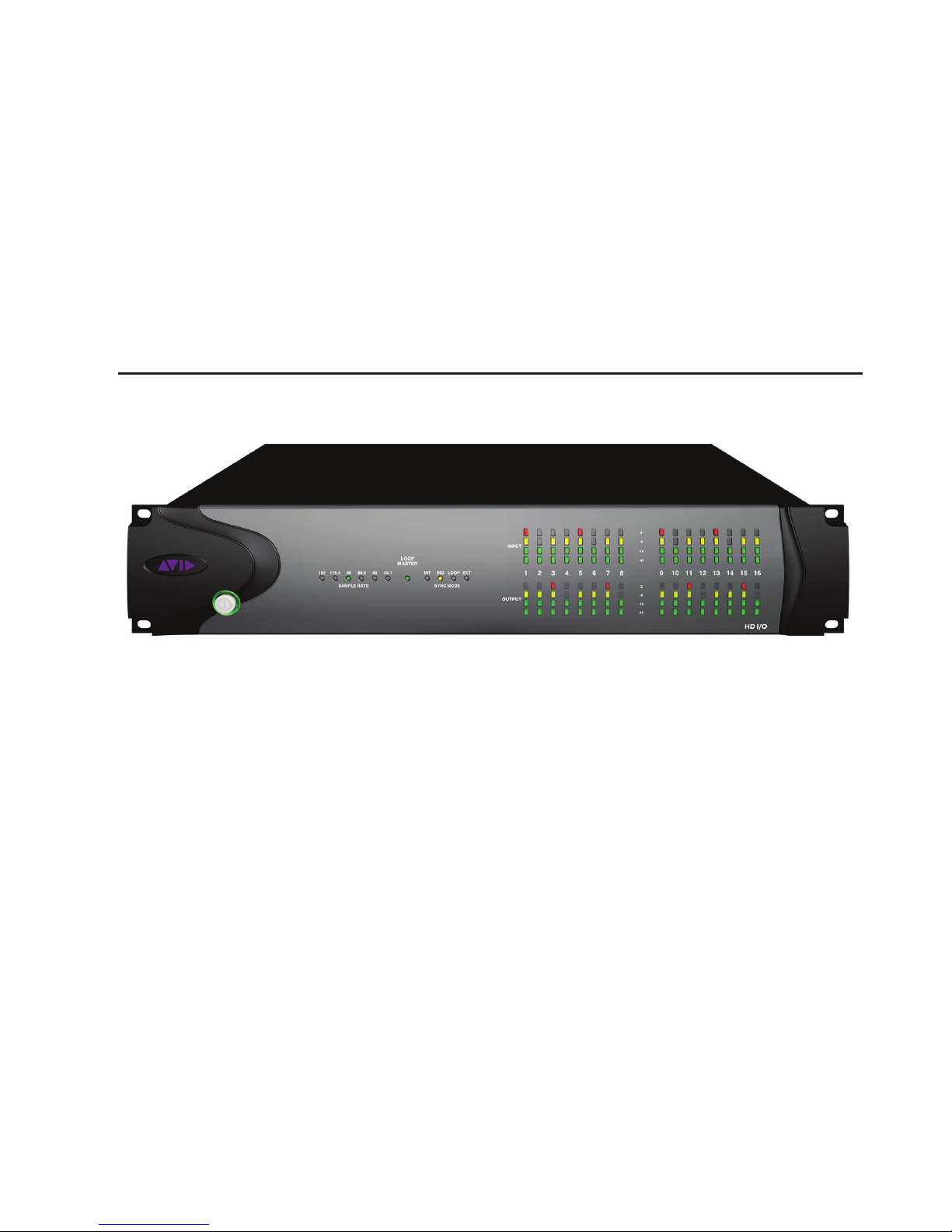
Pro Tools | HD I/O Front Panel
HD I/O Front Panel
Power Switch and LED Ring
This button turns HD I/O on and off. The LED ring
around the power button will light green or orange
to indicate the system status:
Green LED Ring
ered up successfully and is connected to an active
system.
Orange LED Ring
power, but the computer it is connected to is shut
down.
Indicates that the unit has pow-
Indicates that the unit has
Sample Rate
These LEDs display the current sample rate of the
HD I/O internal clock: 44.1 kHz, 48 kHz,
88.2 kHz, 96 kHz, 176.4 kHz, or 192 kHz. The
sample rate can be set in Pro Tools when you create a new session, or in the Hardware Setup or
Playback Engine dialogs if no session is open.
Chapter 2: Pro Tools | HD I/O Overview 5
Page 10
Loop Master LED
The LOOP MASTER LED indicates which audio
interface is the master peripheral. The Loop Master LED will be continuously lit on the current
Loop Master peripheral only, and unlit on all other
peripherals. (Only one Avid HD peripheral can be
Loop Master at a time.) The Loop Master LED will
always be lit with a single interface.
With HDX hardware, Loop Master defaults to the
first audio interface connected to DigiLink Mini
Port 1 on the first card in the system.
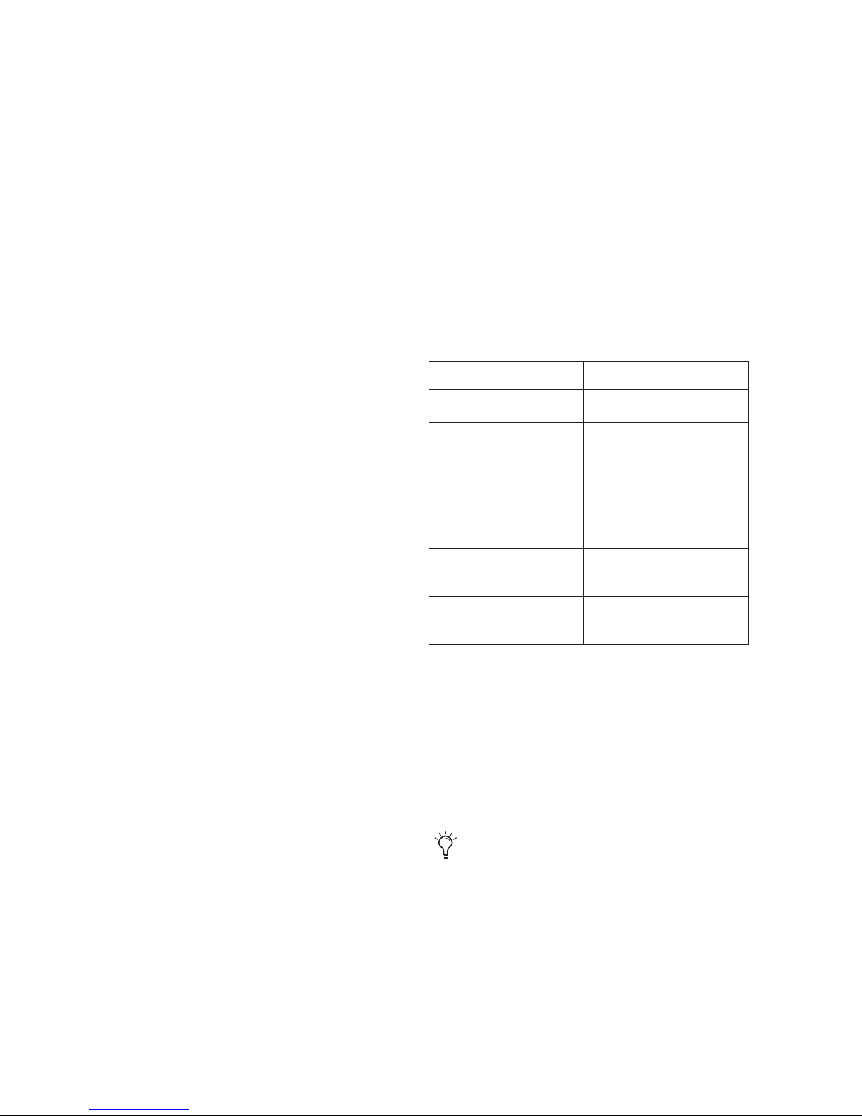
EXT (External)
Indicates that the HD I/O is using
the EXT CLOCK IN port for system synchronization.
When synchronized to Word Clock, External
Clock input and output do not have to be at the
Word Clock rate. EXT CLOCK IN synchronization will typically be 1x the current session sample
rate. However, for sample rates higher than 48
kHz, HD I/O generates a choice of 1x, 2x, or 4x of
a base rate of 44.1 kHz or 48 kHz, as
follows:
With HD Native hardware, Loop Master defaults
to the first audio interface connected to DigiLink
Mini Port 1 on the HD Native card.
For Pro Tools|HD systems, Loop Master defaults
to the first audio interface connected to the primary, or “core” Pro Tools|HD card. On
Pro Tools|HD (for PCIe), this is the Accel Core
card. On Pro Tools|HD (for PCI), this is the HD
Core card.
Sync Mode LEDs
The SYNC MODE LEDs indicate the current
Clock Source as set in Pro Tools.
INT (Internal)
generated by its internal clock, as determined by
the session Sample Rate.
DIG (Digital)
TDIF, Optical (ADAT), Optical (ADAT S/MUX),
or S/PDIF device is providing system clock. If no
valid clock source is detected, HD I/O will switch
to internal clock, the DIG LED will flash, and an
error message will appear on-screen in Pro Tools.
LOOP
Indicates that the HD I/O is slaving to another Avid HD audio interface or SYNC peripheral
using Loop Sync.
Indicates the HD I/O sample clock is
Indicates that an external AES/EBU,
Session Sample Rate Word Clock Support
44.1 kHz 44.1 kHz
48 kHz 48 kHz
88.2 kHz 88.2 kHz
44.1 kHz
96 kHz 96 kHz
48 kHz
176.4 kHz 176.4 kHz
44.1 kHz
192 kHz 192 kHz
48 kHz
Meters
These four-segment LEDs indicate signal level for
each of the sixteen channels. The top row of meters
indicates input levels, and the bottom row shows
output levels. These meters are calibrated at –42
dB, –18 dB, –6 dB, and 0 dB,
respectively.
Note that 0 dB is not to be confused with clipping; use the on-screen meters in Pro Tools
to determine whether a signal is clipping.
Pro Tools | HD I/O Guide6
Page 11
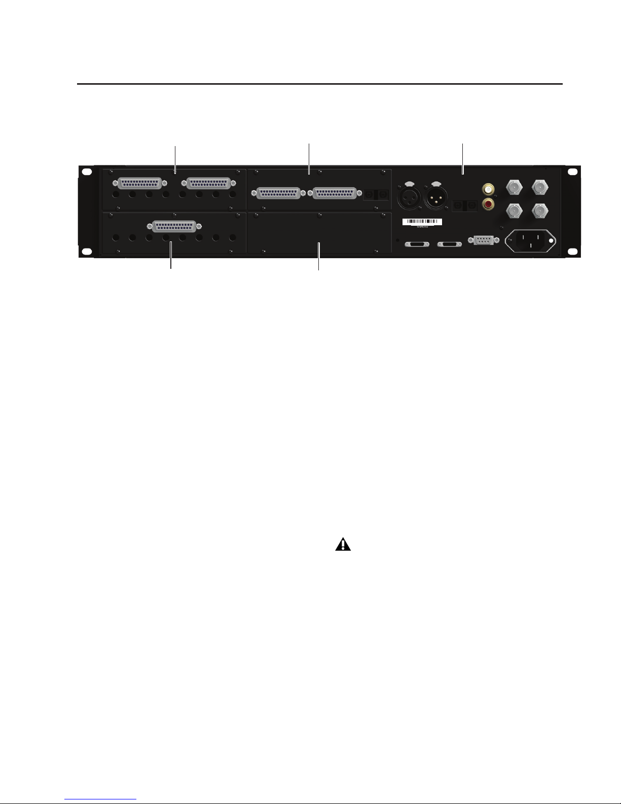
Pro Tools | HD I/O Back Panel
964530300294856
WORD CLOCK
LOOP SYNC
PRIMARY PORT
EXPANSION PORT
IN
OUT
AC ~ 100-240V;50-60HZ; A
S/PDIF
IN
OUT
AES/EBU
INPUT
AES/EBU
OUTPUT
OPTICAL
IN
OUT
ACCESSORY
1
2
3
4
5
6
7
8
ANALOG INPUT
+4 dBu BALANCED
-10 dBV BALANCED
1
2
3
4
5
6
7
8
ANALOG OUTPUT
BALANCED
DIGITAL I/O
AES/EBU
ADAT
IN
TDIF I/O
ADAT
OUT
Bay 2: Analog Out card
Bay 1: Analog In card
Bay 3: Digital I/O card
Bay 4: Empty for Optional card
Enclosure
HD I/O Back Panel, 8 x 8 x 8 configuration shown
Although the HD I/O is a sixteen-channel audio interface, it has up to 94 inputs and outputs available
through its various back panel
connectors.
HD I/O comes in three standard configurations:
• 8 x 8 x 8 analog and digital in and out
• 16 x 16 analog in and out
• 16 x 16 digital in and out
Input and Output Cards
The HD I/O features four bays for HD I/O
Expansion cards. With the standard 8 x 8 x 8 configuration, bays 1–3 contain Analog In, Analog
Out, and Digital I/O cards, respectively. The fourth
bay (as shown in this 8 x 8 x 8 configuration) is an
expansion bay, for which you can purchase an additional Expansion I/O card of your choice.
By installing an optional AD Expansion card, DA
Expansion card, or Digital Expansion card, you
can add even more I/O capacity (up to a maximum
possible 110 inputs and outputs). See Chapter 5,
“Adding or Removing I/O Cards.”
Input and Output cards for 192 I/O are not
supported in HD I/O.
Chapter 2: Pro Tools | HD I/O Overview 7
Page 12
Analog Input
Analog Output
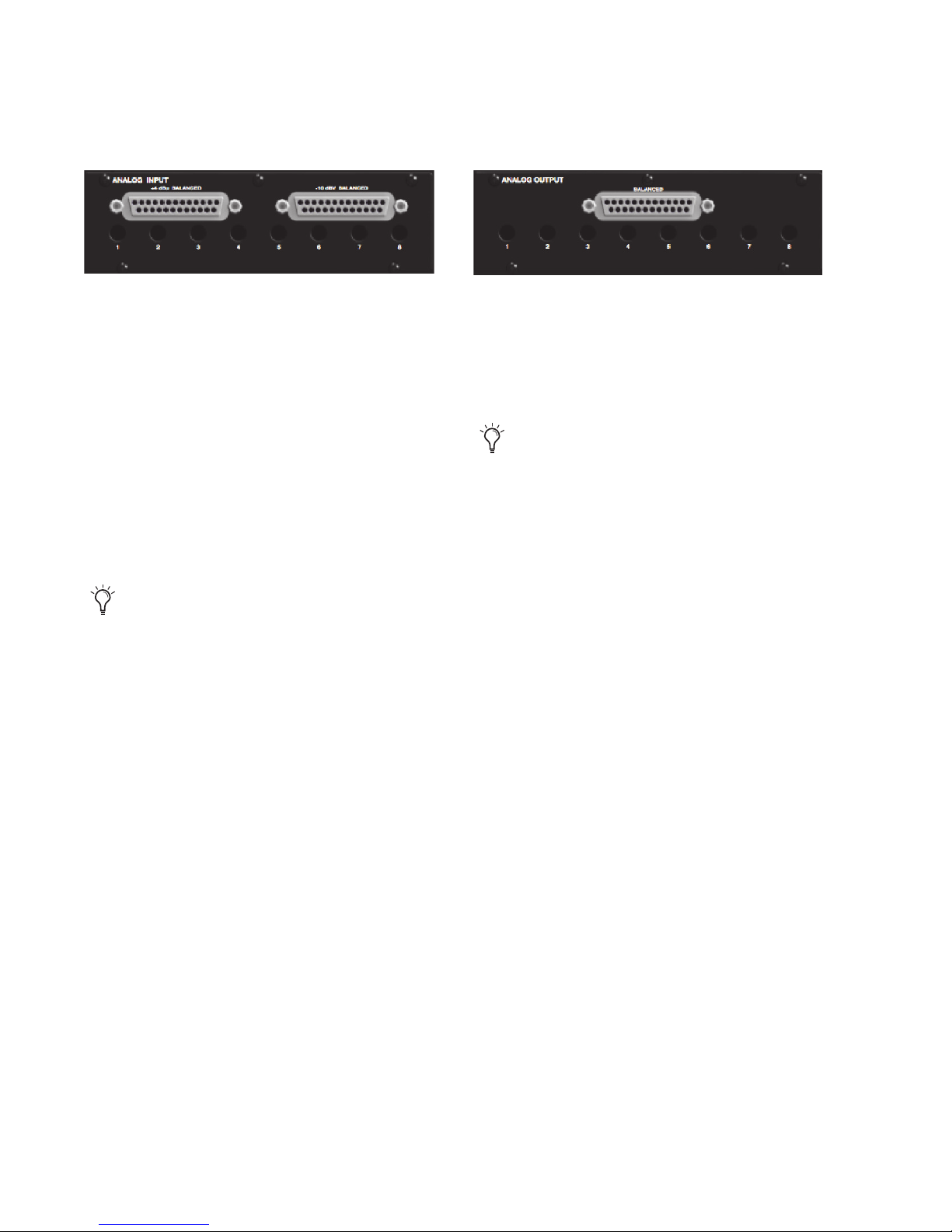
The HD I/O Analog In card contains connectors
for analog audio input with 24-bit, 192 kHz A/D
converters. Input is provided through two discrete
DB–25 connectors (one for +4 dBu sources, and
the other for –10 dBV sources). You can connect
sources at both operating levels and choose between them from within Pro Tools.
+4 dBu Balanced
Provides eight balanced input
channels at +4 dBu nominal operating levels.
–10 dBV Balanced
Provides eight balanced input
channels at –10 dBV nominal operating levels.
Most consumer electronics operate at –10 dBV
levels, and may not feature balanced inputs and
outputs. You can connect –10 dBV signals to
the –10 dBV inputs, but you will need to make
sure that the negative terminals are not connected.
For wiring information, see Chapter 6, “Pinout Diagrams for the DB-25 Connectors.”
The HD I/O Analog Out card contains a single
DB–25 connector and Output Trims for eight
channels of analog audio output. These balanced
outputs operate at +4 dBu levels. See Chapter 6,
“Pinout Diagrams for the DB-25 Connectors.”
For –10 dBV gear, you can switch a jumper
on Analog Output cards (on a channel-bychannel basis) from the default Hi position
to Lo for a –6 dB pad. You can then adjust
the Trim pot for the corresponding output
channels by an additional –4 dB to accommodate –10 dBV gear. For more information, see Chapter 7, “HD I/O Calibration
Mode Instructions.”
Output Trims
The Output Trims below the DB–25 connector are
used to individually calibrate each channel’s output level. For more information, see Chapter 7,
“HD I/O Calibration Mode Instructions.”
For each channel, you can select input level from
within the Hardware Setup dialog (see “Hardware
Setup” on page 21).
Input Trims
The Input Trims below the DB–25 connectors are
used to individually calibrate each channel’s input
level. See “Input Trims” on page 30.
Additionally, the Limiter function helps avoid digital clipping (see“Limiter” on page 26).
Pro Tools | HD I/O Guide8
Page 13
Digital I/O
The inputs on the Digital I/O card feature real-time
sample rate conversion. For example, you can
stream audio with a sample rate of 44.1 kHz into a
96 kHz session.
For more information, see“Hardware Setup”
on page 21.
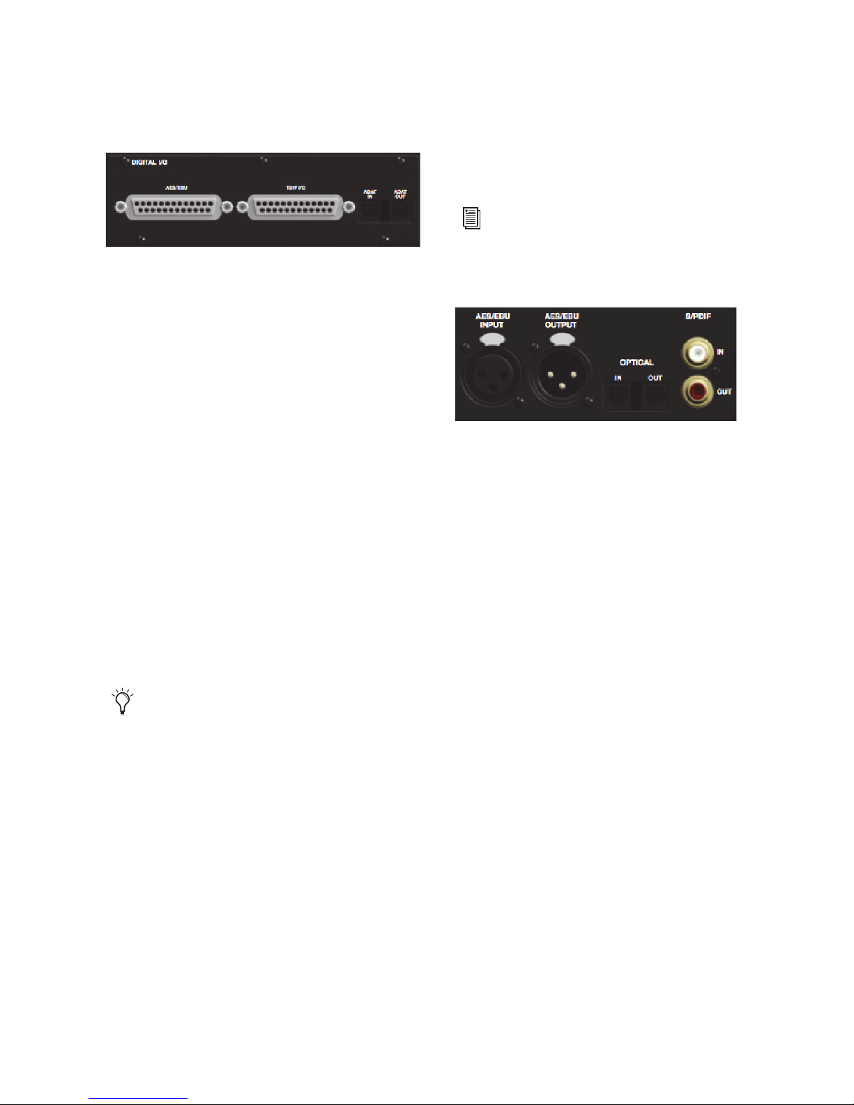
The Digital I/O card contains connectors for eight
channels each of AES/EBU I/O, TDIF I/O, and
Optical (ADAT) I/O. Only one digital format can
be used at a time.
AES/EBU
DB–25 connectors for eight channels of
AES/EBU input and output. Each of the paired
channels is a balanced three-conductor signal, and
supports 192 kHz sample rates in single-wire
mode up to eight channels. Dual-wire mode uses
two HD I/O physical I/O channels of AES/EBU
I/O to carry each single stream of 176.4 kHz or
192 kHz audio. Therefore, only four simultaneous
channels of AES/EBU I/O are available at
176.4 kHz or 192 kHz.
TDIF
DB–25 connectors for eight channels of
TDIF input and output. Conforms to standard
eight-channel TDIF pinouts. For more information, see Chapter 6, “Pinout Diagrams for the DB25 Connectors.”
We recommend using Avid DB-25 TDIF
cables for optimum compatibility.
Optical (ADAT)
Dedicated, eight-channel 24-bit
capable Optical ports (up to 48 kHz), with realtime sample rate conversion on input (only). Note
that Optical S/PDIF is not supported with the Digital I/O card and is supported with the enclosed
Optical ports only (for more information, see “Optical (ADAT) [Encl]” on page 10).
Enclosure Connectors
The right half of the back panel of HD I/O features
a set of non-removable connectors that are
mounted to the enclosure.
These connectors include two channels of
AES/EBU IO, Optical I/O (for another eight channels of ADAT format, or two channels of Optical
S/PDIF), and two channels of coaxial S/PDIF I/O.
On-screen, these connectors are identified as
AES/EBU [Encl], Optical (ADAT) [Encl], Optical
(S/PDIF) [Encl], and S/PDIF [Encl].
Other connectors include Loop Sync, External
Clock, and ports for attaching the HD I/O to HDX,
HD Native, or Pro Tools|HD cards, or to other
Avid HD audio interfaces.
Chapter 2: Pro Tools | HD I/O Overview 9
Page 14
AES/EBU [Encl]
These are balanced, three-conductor XLR connectors that accept and output a stereo, 24-bit
AES/EBU audio signal. These two ports support
up to 192 kHz sample rates.
Optical (ADAT) [Encl]
These Optical ports provide up to eight channels of
Optical (ADAT) input and output, or two channels
(stereo) optical S/PDIF input and output. Optical
(ADAT) mode supports sample rates up to 48 kHz.
Using S/MUX, these Optical ports support provide
up to four channels of Optical S/MUX input and
output at sample rates of 88.2 and 96 kHz, and up
to two channels of Optical S/MUX input and output at sample rates of 176.4 and 192 kHz. In TOSLink mode, the ports support two channels of Optical input and output at sample rates up to 96 kHz.
Configure HD I/O for ADAT S/MUX on the
enclosed ADAT port and also on the ADAT
port on the Digital I/O card to get 8 channels
at 88.2/96 kHz or 4 channels at
176.4/192 kHz.
About Lightpipe-Compatible Devices
Lightpipe is an industry standard, eight-channel
optical digital audio connection created by Alesis.
Lightpipe is found on many devices, including Optical (ADAT) decks, modular digital multitracks
(MDMs), A/D or D/A converters, S/MUX, and
digital consoles.
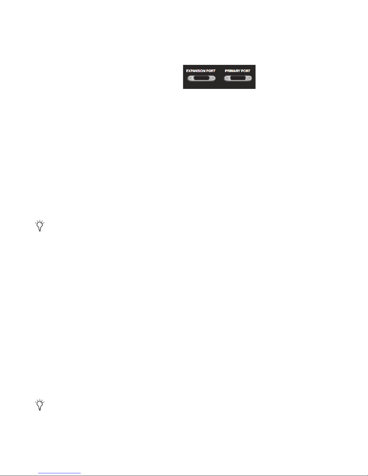
DigiLink Mini Ports
PRIMARY PORT
Use the PRIMARY PORT to connect HD I/O to
HDX or HD Native cards using a DigiLink Mini
cable, or to Pro Tools|HD cards using a DigiLink
cable with a DigiLink Mini adapter.
The Primary port sends and receives 32 channels to
and from an HDX, HD Native, or Pro Tools|HD
card. Input and output channels 17–32 (if active)
are passed through to the EXPANSION PORT.
EXPANSION PORT
The EXPANSION PORT lets you connect an additional Avid HD audio interface to HD I/O. The
EXPANSION PORT passes input and output
channels 17–32 to the expansion (or secondary)
audio interface.
This port is only available when HD I/O is connected directly to an HDX, HD Native, or
Pro Tools|HD card. It is not available when the
HD I/O is connected to the Expansion Port on another audio interface.
S/PDIF Digital In and Out
These are unbalanced RCA jacks that receive and
send two channels of S/PDIF audio. S/PDIF supports up to 24-bit audio, at sample rates up to 192
kHz.
To maintain data integrity and minimize jitter, use only 75-ohm coaxial cable for
S/PDIF connections.
Pro Tools | HD I/O Guide10
Page 15
DigiLink Mini Cables and Adapters
Avid provides various cables and adapters to connect Avid HD audio interfaces to HDX,
HD Native, and Pro Tools|HD cards.
For more information about DigiLink Mini
cables and adapters, visit the Avid website
(www.avid.com).
Clock and Synchronization Ports
DigiLink Mini Cables
Use a DigiLink Mini cable to connect an HD I/O to
an HDX or HD Native card, or to other Avid HD
audio interface (such as another HD I/O).
There are five different lengths of DigiLink Mini
cables:
• 18 in (0.46m)
• 12 ft (3.6m) (sold separately)
• 25 ft (7.62m) (sold separately)
• 50 ft (15.25m), the maximum length supported for 176.4 kHz and 192 kHz sessions
(sold separately)
• 100 ft (30.5m), the maximum length supported by 88.2 kHz and 96 kHz sessions (sold
separately)
DigiLink Mini Adapters
Use a DigiLink cable with a DigiLink Mini adapter
to connect HD I/O to a Pro Tools|HD card. You
can also use a DigiLink Mini adapter to connect
HD I/O to legacy Pro Tools|HD audio interfaces
(such as 192 I/O).
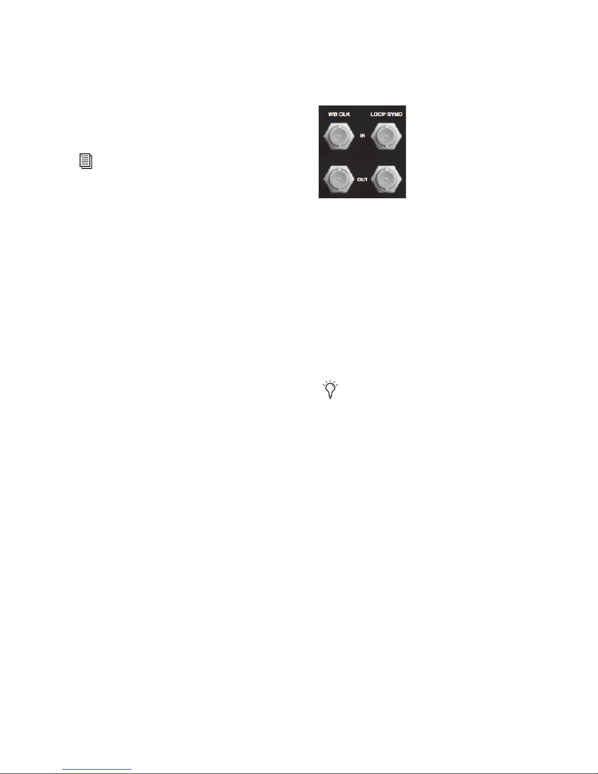
WD CLOCK IN and OUT
The Word Clock I/O ports are standard BNC connectors that receive and output word clock signal.
These ports can be used to synchronize HD I/O
with any word clock-capable device.
Word Clock In can be configured by selecting it as
the Clock Source in the Hardware Setup dialog in
Pro Tools. Word Clock Out can also be configured
in the Hardware Setup dialog using the External
Clock Output selector.
Because crucial timing data is passed
through the Loop Sync and Word Clock
ports, you should use high-quality, 75-Ohm
RG–59 cables for making connections.
There are two types of DigiLink Mini adapters:
• 12 in DigiLink Mini female to DigiLink male
• 12 in DigiLink Mini male to DigiLink female
Chapter 2: Pro Tools | HD I/O Overview 11
Page 16

LOOP SYNC In and Out
Loop Sync is a dedicated clock loop for synchronizing multiple Pro Tools|HD peripherals together
(multiple audio interfaces, or a SYNC HD and one
or more audio interfaces). Loop Sync technology
lets you synchronize to any digital peripheral connected to any of the Pro Tools|HD audio interfaces
in your Pro Tools system. Loop Sync uses a word
clock signal based on sample rates of either
44.1 kHz or 48 kHz. As sample rate increases in
the system, Loop Sync continues to operate at a
base rate of 44.1 kHz or 48 kHz, depending upon
the higher rate.
The Loop Sync In and Out ports are standard BNC
connectors that output a 1x Word clock signal.
Loop Sync should only be used to chain multiple
Pro Tools|HD peripherals together (such as
Pro Tools|HD audio interfaces and SYNC HD).
AC Power
This connector accepts a standard AC power cable.
HD I/O is auto power-selecting (100V to 240V)
and will automatically work with a standard modular cable (IEC) to connect to AC power outlets in
any country.
Accessory Port
This port currently has no functionality.
Pro Tools | HD I/O Guide12
Page 17

Chapter 3: Connecting Pro Tools | HD I/O
Pro Tools | HD I/O provides up to sixteen channels
of analog and digital I/O with HD I/O with HDX,
HD Native, or Pro Tools|HD hardware.
HDX
With Pro Tools | HDX hardware, HD I/O is
connected to the HDX card using a DigiLink Mini
cable. You can connect additional HD audio interfaces to your system using the Expansion port on
the back of HD I/O, the second DigiLink Mini Port
on the HDX card, or by using additional HDX
cards. See “Connecting Pro Tools | HD I/O to
Pro Tools | HDX Cards” on page 14.
For more information about installing HDX
cards, see the Pro Tools | HDX Installation
Guide
.
HD Native
With Pro Tools | HD Native hardware,
HD I/O is connected to the HD Native card using a
DigiLink Mini cable. You can connect additional
HD audio interfaces to your system using the Expansion port on the back of HD I/O or the second
DigiLink Mini Port on the HD Native card. See
“Connecting Pro Tools | HD I/O to a
Pro Tools | HD Native Card” on page 16.
Pro Tools|HD
With Pro Tools|HD hardware,
HD I/O is connected to a Pro Tools|HD card
using a DigiLink cable with a DigiLink Mini
adapter. You can connect additional HD audio interfaces to your system using the Expansion port
on the back of HD I/O or using additional
Pro Tools|HD cards. See “Connecting
Pro Tools | HD I/O to Pro Tools|HD Cards” on
page 18.
For more information about installing
Pro Tools|HD cards, see the Pro Tools|HD
User
Guide
.
Rack Mounting HD Audio Interfaces
HD I/O and all Avid HD audio interfaces need
room at their sides to maintain proper air flow for
cooling. Do not block the sides of the unit or disconnect the internal fan. If the units are rackmounted in a case, remove the case lids or doors
before operating the system. Failure to do so can
result in the units overheating very quickly, which
can permanently damage sensitive
components.
For more information about installing the HD
Native card, see the Pro Tools | HD Native
Installation
Guide
.
Chapter 3: Connecting Pro Tools | HD I/O 13
Page 18
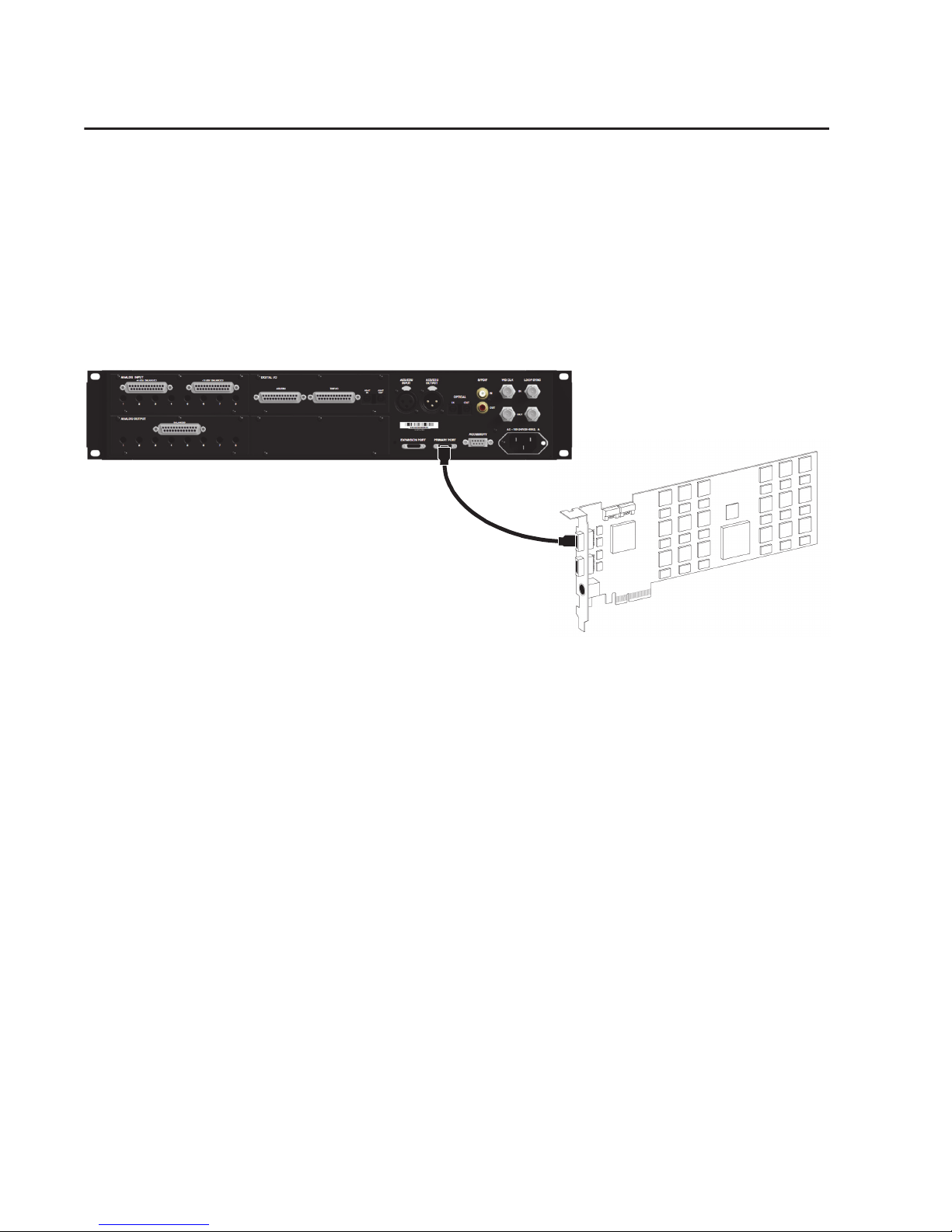
Connecting Pro Tools | HD I/O to Pro Tools | HDX Cards
Each HDX card supports up to 64 channels of audio input and output. To get a full 64 channels of I/O, you
can connect up to four 16-channel HD I/O to an HDX card. Two of the interfaces connect directly to DigiLink Mini Ports 1 and 2, and the other two HD I/O connect to the Expansion ports on first two HD I/O.
To connect HD I/O to an HDX card:
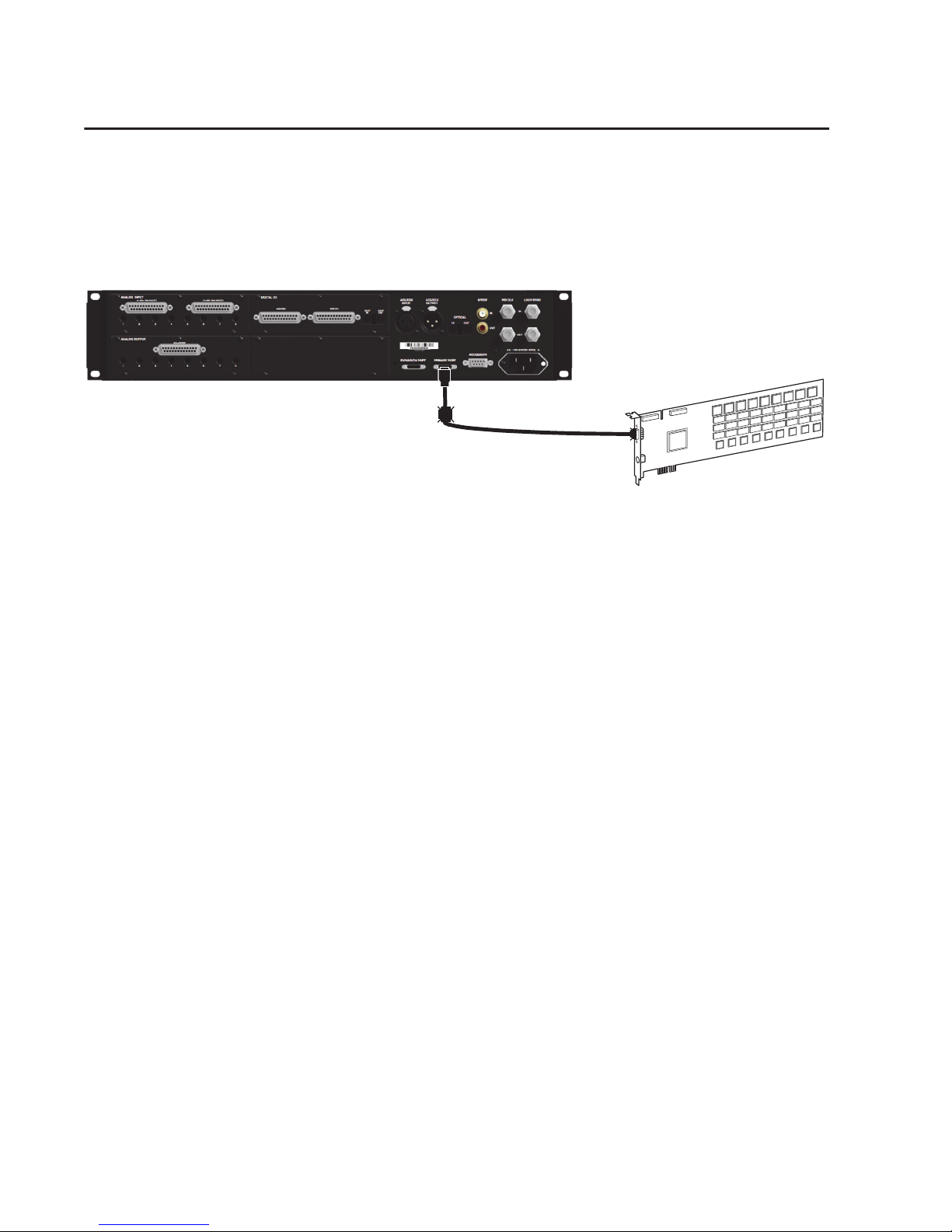
Connect the HD I/O Primary Port to DigiLink Mini Port 1 on the HDX card using a DigiLink Mini cable.
Figure 1. HD I/O connected to the DigiLink Mini Port 1 on an HDX card
To connect additional HD I/O audio interfaces:
1
After connecting the primary audio interface,
connect additional HD I/O (or other compatible
audio interfaces) by doing one of the following:
• Connect the Primary Port of the secondary interface to the Expansion Port of the primary
interface with a DigiLink Mini cable.
• Connect the Primary Port of the secondary in-
Connecting Loop Sync
If you are using two or more HD audio interfaces
or a SYNC peripheral, Loop Sync must be connected to maintain proper clock synchronization
among the devices. For an example of connecting
multiple Avid HD audio interfaces, see Figure 2 on
page 15. For examples that include a SYNC peripheral, see the SYNC HD Guide.
terface to DigiLink Mini Port 2 on the HDX
card.
2
Repeat the preceding with additional HDX
cards.
3
Make the necessary Loop Sync connections
(see “Connecting Loop Sync” on page 14).
To make Loop Sync connections:
1
Connect the Loop Sync Out of each interface to
the Loop Sync In of the next interface with a
BNC cable.
2
Connect the Loop Sync Out of the last interface
to the Loop Sync In of the primary interface or
SYNC peripheral with a BNC cable.
Pro Tools | HD I/O Guide14
Page 19

Second HDX card
First HDX card
Figure 2. Making DigiLink and Loop Sync connections with two HDX cards, one HD OMNI, and five HD I/Os
Chapter 3: Connecting Pro Tools | HD I/O 15
Page 20
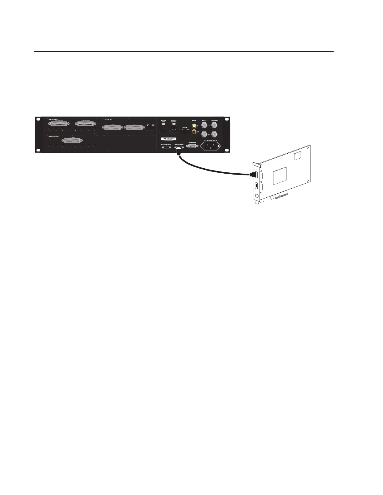
Connecting Pro Tools | HD I/O to a Pro Tools | HD Native Card
To connect HD I/O to an HD Native card:
Connect the HD I/O Primary Port to DigiLink Mini Port 1 on the HD Native card using the included
DigiLink Mini cable.
PORT 1PORT 2
Figure 3. HD I/O connected to the DigiLink Mini Port 1 on an HD Native card
To connect two HD I/Os to an HD Native card:
1
Connect the Primary Port to DigiLink Mini Port 1 on the HD Native card using the included DigiLink
Mini cable.
2
Connect the additional HD I/O (or other compatible Pro Tools audio interface) by doing one of the
following:
• Connect the Primary Port of the secondary interface to the Expansion Port of the primary
interface with an additional DigiLink Mini cable (or DigiLink to DigiLink Mini adapter).
• Connect the Primary Port of the secondary interface to DigiLink Mini Port 2 on the HD Native card.
3
Make the necessary Loop Sync connections (see “Connecting Loop Sync” on page 17).
Pro Tools | HD I/O Guide16
Page 21
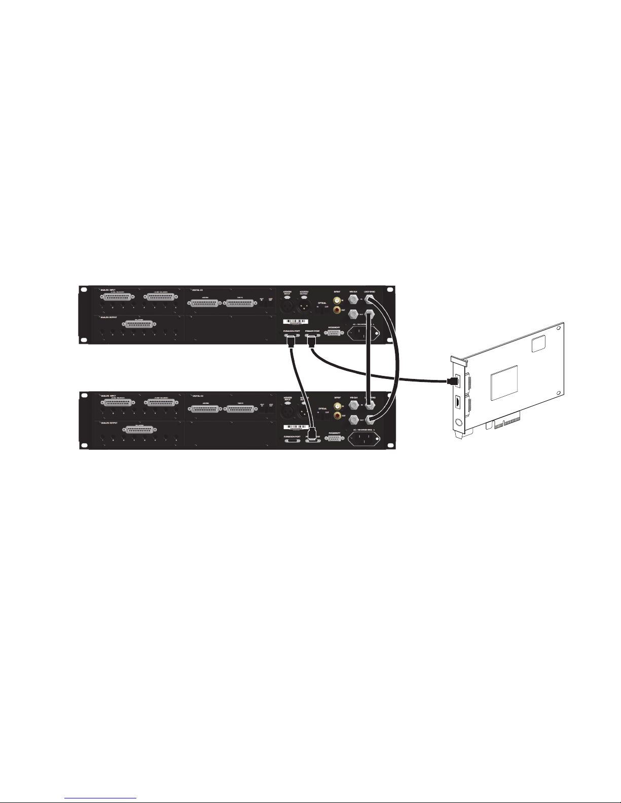
Connecting Loop Sync
PORT 1PORT 2
If you are using two or more Pro Tools audio interfaces or a SYNC peripheral, Loop Sync must be
connected to maintain proper clock synchronization among the devices. For examples that include a SYNC
peripheral, see the SYNC HD Guide. For an example of connecting multiple Avid HD audio
interfaces, see Figure 4 below.
To make Loop Sync connections:
1
Connect the Loop Sync Out of each interface to the Loop Sync In of the next interface with a BNC
cable.
2
Connect the Loop Sync Out of the last interface to the Loop Sync In of the primary interface or SYNC
peripheral with a BNC cable.
Figure 4. DigiLink Mini and Loop Sync connections for two HD I/Os with HD Native
Chapter 3: Connecting Pro Tools | HD I/O 17
Page 22
Connecting Pro Tools | HD I/O to Pro Tools|HD Cards
12-foot DigiLink cable with
DigiLink Mini adapter
To connect HD I/O to a Pro Tools|HD card:
Connect HD I/O Primary Port to the DigiLink Port on the first available Pro Tools|HD card with a DigiLink cable (included with your Pro Tools|HD hardware) and a DigiLink Mini adapter.
Figure 5. HD I/O connected to the DigiLink Port on a Pro Tools|HD Accel Core card (16-channel I/O system)
To connect multiple HD I/Os to a Pro Tools|HD system:
1
Connect the Primary Port of the first HD I/O to the DigiLink Port on the Pro Tools|HD Accel Core card
with a DigiLink cable (included with your Pro Tools|HD system) and a DigiLink Mini adapter.
2
Do one of the following:
• Connect the Primary Port of the second HD I/O to the Expansion Port on the first HD I/O with the
included 18-inch DigiLink Mini cable.
• Connect the Primary Port of the second HD I/O to the next available Pro Tools|HD card with a
DigiLink cable and a DigiLink to DigiLink Mini adapter.
3
Connect additional HD I/Os to additional Pro Tools|HD cards.
4
Make the necessary Loop Sync connections.
Pro Tools | HD I/O Guide18
Page 23
Connecting Loop Sync
Pro Tools|HD Accel Core card
Pro Tools|HD Accel card
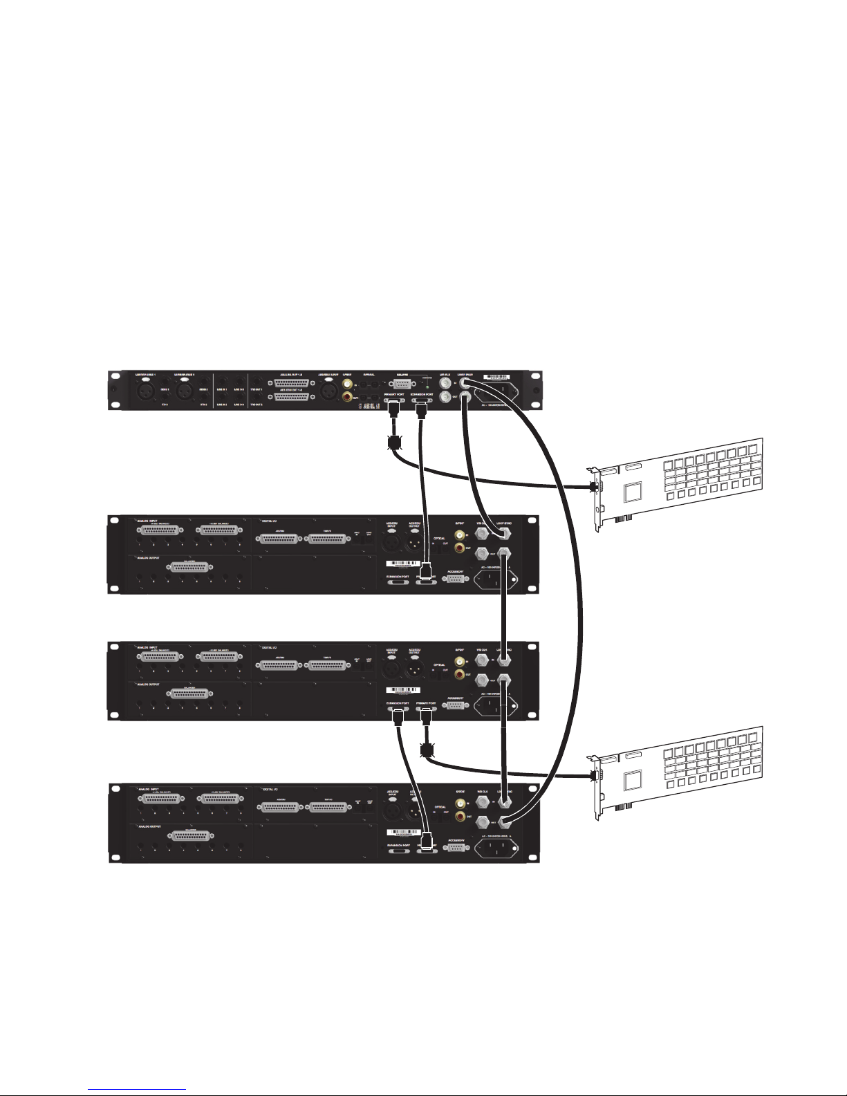
If you are using two or more Pro Tools audio interfaces or a SYNC peripheral, Loop Sync must be
connected to maintain proper clock synchronization among the devices. For an example of connecting
multiple Avid HD audio interfaces, see Figure 6 below.
To make Loop Sync connections:
1
Connect the Loop Sync Out of each interface to the Loop Sync In of the next interface with a BNC
cable.
2
Connect the Loop Sync Out of the last interface to the Loop Sync In of the primary interface or SYNC
peripheral with a BNC cable.
Figure 6. Making DigiLink and Loop Sync connections with two Pro Tools|HD cards, one HD OMNI,
and three HD I/Os
Chapter 3: Connecting Pro Tools | HD I/O 19
Page 24

Pro Tools | HD I/O Guide20
Page 25
Chapter 4: Configuring Pro Tools | HD I/O in
Pro Tools | HD Software
This chapter explains how to configure
Pro Tools | HD Software for use with
Pro Tools | HD I/O.
For more information about configuring
Pro Tools, see the Pro Tools Reference
Guide
.
Hardware Setup
In the Hardware Setup dialog, Pro Tools lets you
set the default sample rate (if no session is open)
and clock source for your system, and provides access to a range of controls specific to each type of
audio interface.
Default Sample Rate
The
Sample Rate
sample rate when you create a new session. (This
setting is available in the Hardware Setup dialog
only when no session is open.)
setting appears as the default
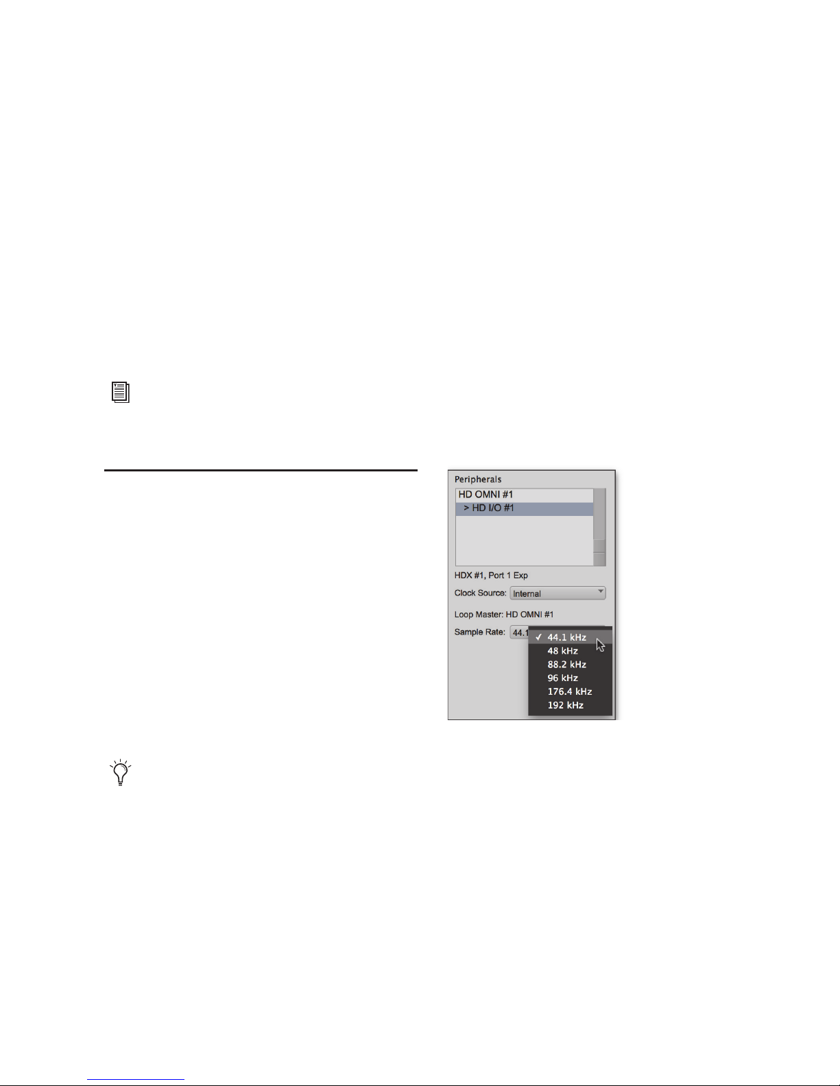
To change the default Sample Rate for new
sessions:
1
If a Pro Tools session is currently open, close it.
2
Choose
3
From the
Setup > Hardware
Sample Rate
pop-up menu, select the
.
sample rate that you want.
Selecting the default sample rate
You can change the sample rate when
creating a new Pro Tools session by
selecting a different sample rate in the
New Session dialog.
4
Click OK.
Chapter 4: Configuring Pro Tools | HD I/O in Pro Tools | HD Software 21
Page 26
High Sample Rates and Expanded
Pro Tools|HD Systems
With 176.4 kHz and 192 kHz sample rates, as
many as four Pro Tools|HD cards can be used. Any
additional cards (up to the total system maximum
of seven cards) will switch to Inactive mode. The
Pro Tools|HD cards and any attached peripherals
will become active again when the sample rate is
set to 96 kHz or lower. See the Pro Tools
Expanded Systems Guide for more information.
Clock Source
The Pro Tools Hardware Setup dialog lets you set
Clock Source
the
Internal
If you are recording an analog signal
directly into Pro Tools, you will usually use the
Pro Tools
External
Internal
If you are transferring material into
Pro Tools from an external digital device, or if you
utilize a common house clock signal, you will need
to synchronize Pro Tools to that digital device or
common signal. Depending on your audio interface configuration and the selected sample rate,
external options can include:
for the system.
clock source.
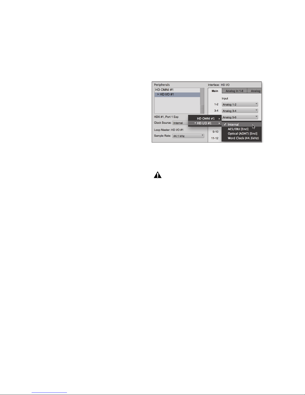
To select the Clock Source:
1
Choose
2
From the
Setup > Hardware.
Clock Source
pop-up menu, select the
clock source.
Selecting the Clock Source
3
Click OK.
Your digital input device must be connected
and powered on for Pro Tools to synchronize
to it. If your input device is not powered on,
leave the Clock Source set to Internal.
S/PDIF [Encl]
•
Optical (S/PDIF) [Encl]
•
AES/EBU [Encl]
•
AES/EBU 1–8
•
(at all sample rates)
(Single Wire in stereo pairs at
all sample rates)
AES/EBU 1–4 (Dual Wire)
•
176.4 and 192 kHz)
ADAT 1–8
•
•
ADAT S/MUX 1–4
•
ADAT S/MUX 1–2
TDIF 1–8
•
Optical ADAT [Encl]
•
Word Clock
•
Pro Tools | HD I/O Guide22
(at 44.1 and 48 kHz)
(at 44.1 and 48 kHz)
(at all sample rates)
(up to 96 kHz)
(at all sample rates)
(in stereo pairs at
(at 88.2 and 96 kHz)
(at 176.4 and 192 kHz)
(at 44.1 and 48 kHz)
Page 27
Identify
If you have multiple audio interfaces of the same
type connected to your system, you should confirm
the identity of each interface. This ensures that you
select the appropriate interface in the Peripherals
list when defining its inputs and outputs, and other
settings, in the Hardware Setup dialog.
To identify audio interfaces in your system:
1
Choose
2
From the Peripherals list, select an audio
interface connected to your system.
3
Select the
left corner of the Hardware Setup dialog. This
illuminates all the LEDs on the front panel of
the selected audio interface.
4
Make a note of which interface in your studio
setup corresponds to the identified interface.
Setup > Hardware.
Use the Up and Down Arrow keys to scroll
though the Peripherals list in the Hardware
Setup dialog.
Identify
option, located in the lower
Configuring HD I/O
To configure controls for HD I/O:
1
Choose
2
From the Peripherals list, select the HD I/O
audio interface.
3
Click the
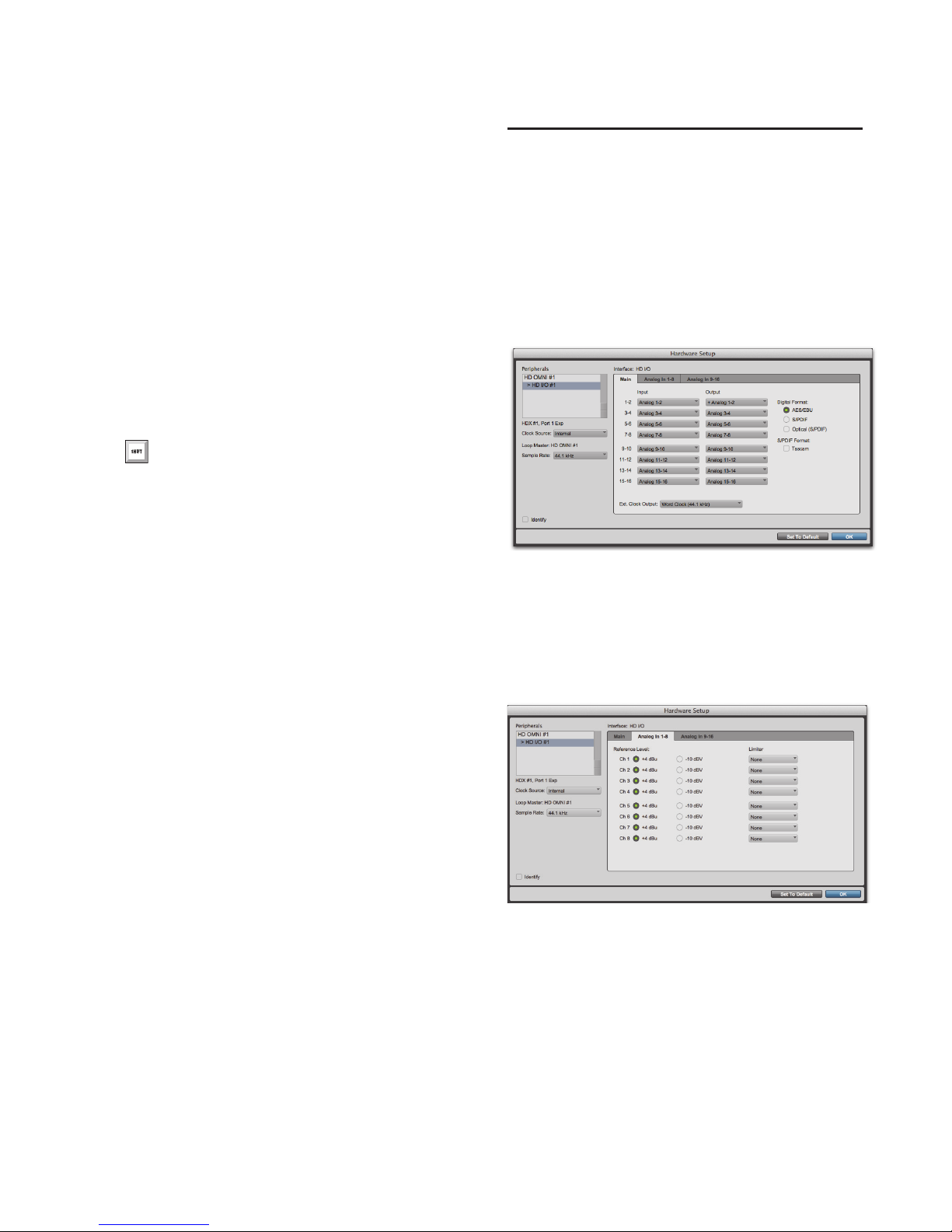
HD I/O Hardware Setup, Main page
4
If you have at least one HD I/O AD card, click
the
you have two HD I/O AD cards, this tab is labeled
Setup > Hardware
Main
tab and configure the options.
Analog In
Analog In 1–8
tab and configure the options. If
.
.
5
Repeat the above steps for each additional audio
interface in your setup.
HD I/O Hardware Setup, Analog In page
Chapter 4: Configuring Pro Tools | HD I/O in Pro Tools | HD Software 23
Page 28
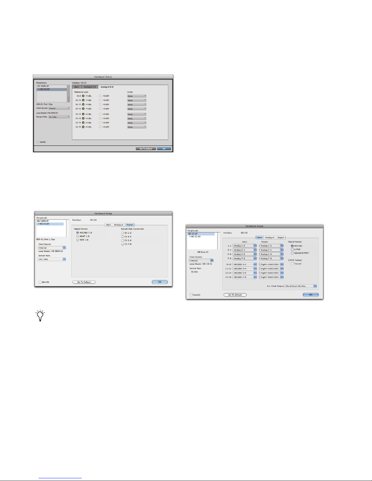
5
If you have two HD I/O AD cards, click the
alog In 9–16
HD I/O Hardware Setup, Analog In 9–16 page
6
If you have at least one HD I/O Digital card,
click the
tab and configure the options.
Digital
tab (this is labeled
Digital 1–8
you have two HD I/O Digital card installed) and
configure the options.
An-
if
HD I/O Hardware Setup Options
HD I/O provides multiple pages of Hardware
Setup options depending on the configuration.
Main Page
HD I/O supports up to sixteen channels of
simultaneous input and output in multiple I/O
formats (including analog, AES/EBU, ADAT
Optical, S/MUX, S/PDIF, and TDIF).
The Main page of the Hardware Setup dialog is
where you define which physical inputs and outputs on your audio interface are routed to available
input and output channels in Pro Tools. You can
think of this window as a patchbay that lets you
route any of the input pairs or output pairs on your
Pro Tools audio interfaces to channel assignments
in the Pro Tools mixer.
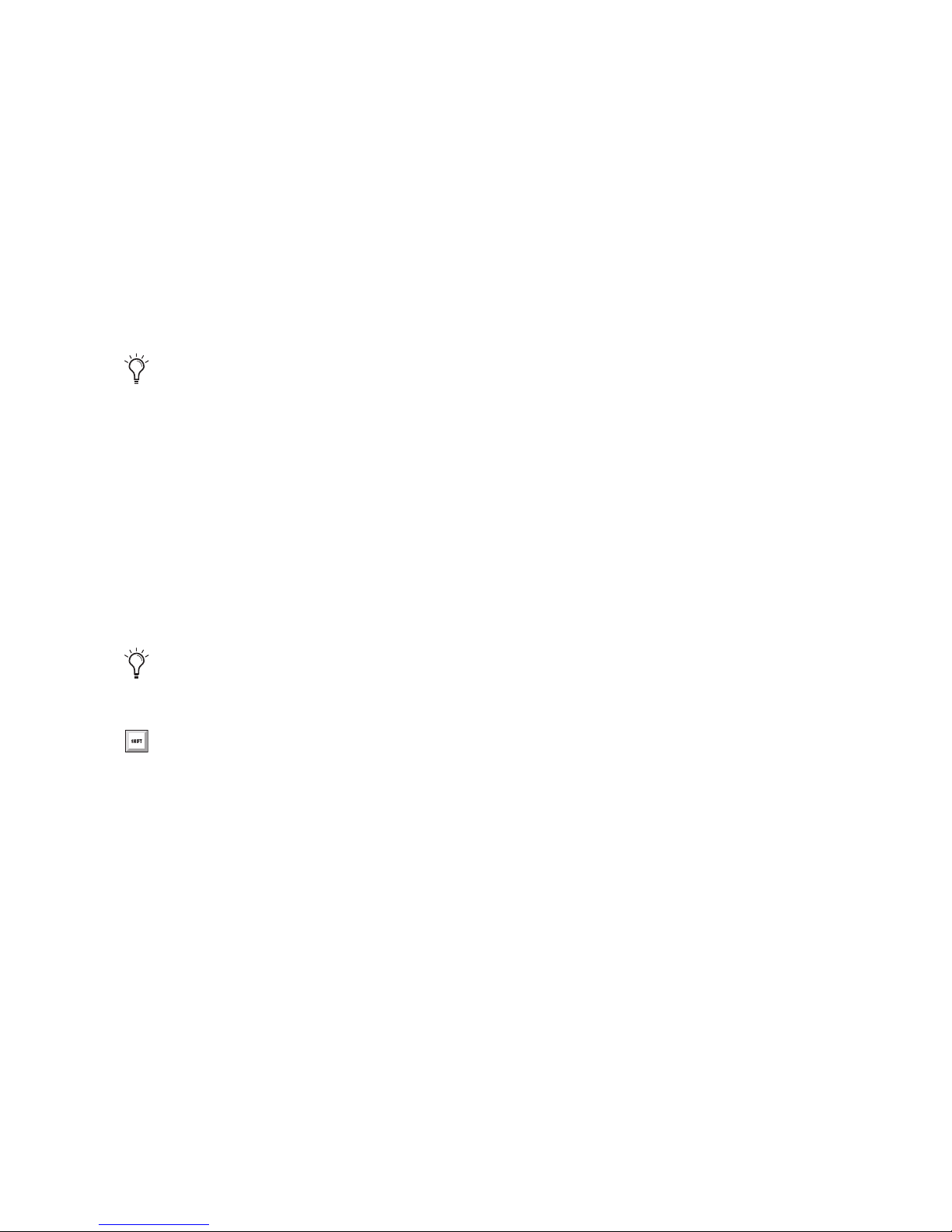
HD I/O Hardware Setup, Digital page
At session sample rates above 48 kHz, sample
rate conversion for the TDIF and Optical
(ADAT) inputs on the HD I/O Digital card is
automatically enabled on all eight inputs of
the selected format unless you are using
S/MUX Optical.
7
If you have two HD I/O Digital cards installed,
click the
Digital 9–16
tab and configure the
options.
8
When you are finished, click OK.
Pro Tools | HD I/O Guide24
HD I/O Hardware Setup, Main page (8 x 8 x 8 shown)
Page 29
Input
Inputs and Outputs of Similar Formats
Select the corresponding physical inputs from the
Input pop-up menu for each stereo pair of
Pro Tools Input channels (1–2, 3–4, ...15–16).
Which physical inputs are available depends on the
sample rate and on which HD I/O Expansion cards
you have installed (for example, if no HD I/O AD
card is installed, no analog inputs will be available).
These settings are saved with the system, not
with the session.
Output
Select the corresponding physical outputs from the
Output pop-up menu for each stereo pair of
Pro Tools Output channels (1–2, 3–4, ...15–16).
Which physical outputs are available depends on
the sample rate and on which HD I/O Expansion
cards you have installed (for example, if no HD I/O
DA card is installed, no analog outputs will be
available).
Inputs and outputs of similar formats are differentiated in the input and output channel pop-up
menus. For example, the AES/EBU inputs and outputs in the HD I/O enclosure are listed as
AES/EBU [Encl]
, while the AES/EBU inputs and
outputs on a HD I/O Digital card are listed (in
pairs) as
5–6,
AES/EBU 1–2, AES/EBU 3–4, AES/EBU
and
AES/EBU 7–8
. For HD I/Os equipped
with an second Digital card, the additional
AES/EBU I/O ports on the optional card are listed
AES/EBU 9–10, AES/EBU 11–12, AES/EBU
as
and
13–14,
Digital Format
AES/EBU 15–16.
Select from the following digital input formats for
the built-in digital I/O enclosure (configure the options for any additional HD I/O Digital cards by
Digital
clicking the corresponding
AES/EBU
Provides up to two channels of
tab):
AES/EBU input.
These settings are saved with the system, not
with the session.
Control-click (Mac) or Start-click (Windows) to select multiple Inputs or Outputs. Command-Option-click (Mac) or
Control-Alt-click to cascade all Input or
Output settings.
S/PDIF
Optical (S/PDIF)
Two channels of S/PDIF (coaxial) input.
Two channels of S/PDIF (optical)
input up to 96 kHz. This option is not available at
sample rates higher than 96 kHz.
S/PDIF Format
For S/PDIF (Sony/Phillips Digital Interface Format) compatibility with Tascam DA-30 DAT recorders, select the
Tascam
option under S/PDIF
Format.
Chapter 4: Configuring Pro Tools | HD I/O in Pro Tools | HD Software 25
Page 30
Ext. Clock Output
If you want to send clock output to other devices
attached to HD I/O, select the appropriate output
from the
Ext. Clock Output
pop-up menu.
The available options for
Ext. Clock Output
change
depending on the session sample rate. See the table
below for a list of default external clock settings
and available options.
Ext. Clock Output options by sample rate
Sample Rate
44.1 kHz Word Clock
48 kHz Word Clock
88.2 kHz Word Clock
96 kHz Word Clock
176.4 kHz Word Clock
192 kHz Word Clock
Available Ext.
Clock Default
(44.1 kHz)
(48 kHz)
(88.2 kHz)
(96 kHz)
(176.4 kHz)
(192 kHz)
Available Ext.
Clock Option
N/A
N/A
Word Clock
(44.1 kHz)
Word Clock
(48 kHz)
Word Clock
(44.1 kHz)
Word Clock
(48 kHz)
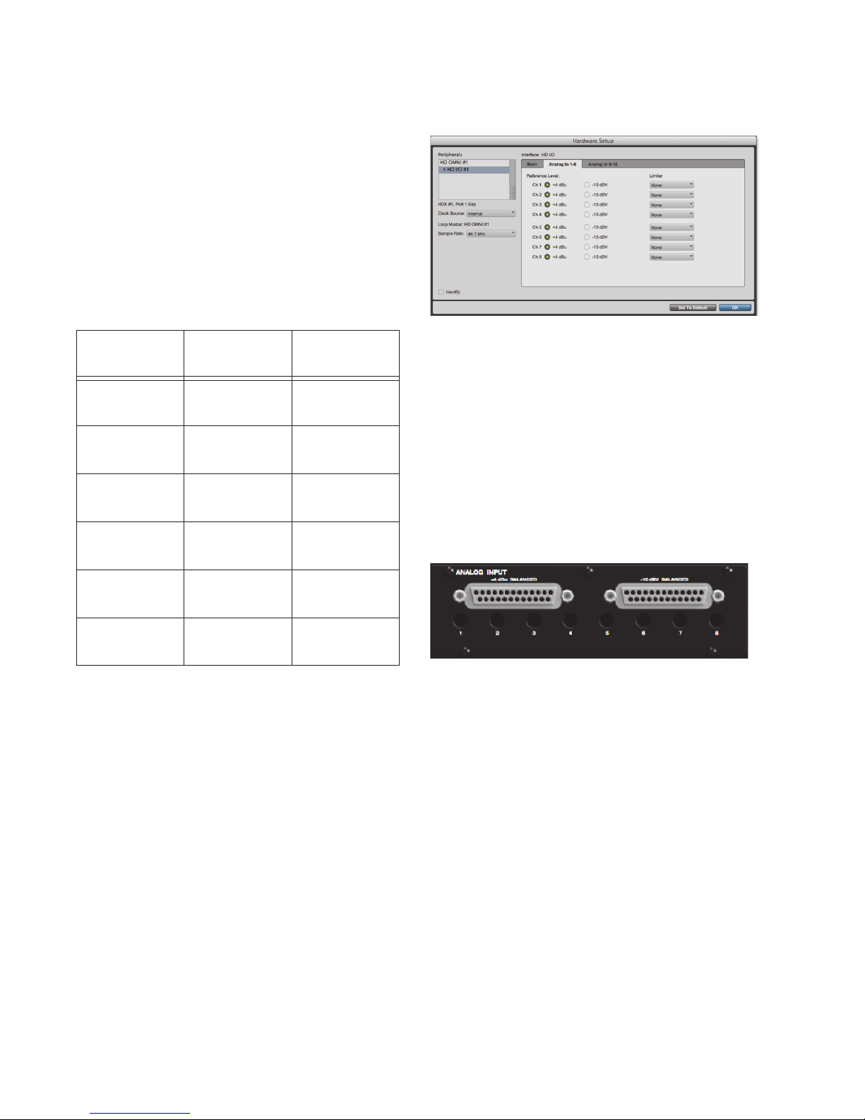
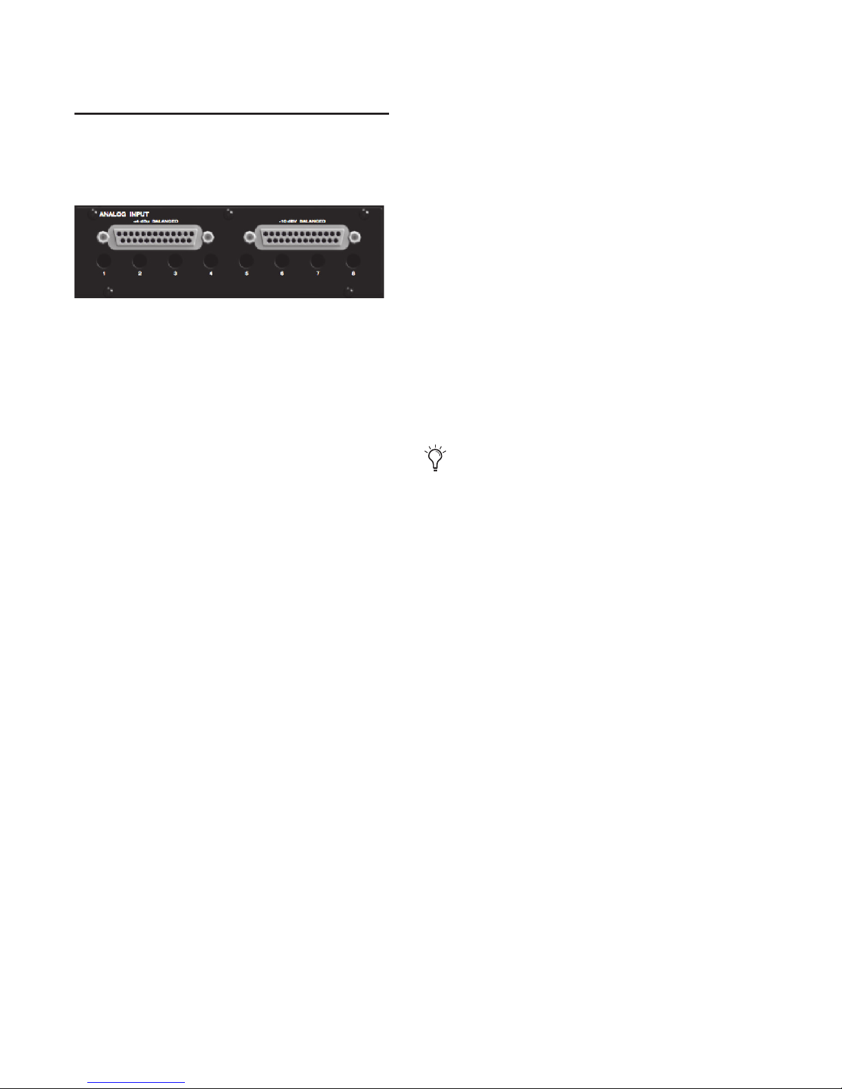
Analog In Page
Hardware Setup, Analog In page
Reference Level
Select the appropriate
Reference Level
for each of
the available analog input channels. This lets you
select the analog audio input source on a channelby-channel basis. The
+4 dBu
option routes audio
from the physical +4 dBu Balanced DB-25 Analog
Input port on the card. The
–10 dBV
option routes
audio from the physical –10 dBV Balanced DB-25
Analog Input port on the card.
+4 dBu and –10 dBV DB-25 Analog Input ports
Limiter
The Analog In page of the Hardware Setup dialog
lets you set the Reference Level for the physical
analog inputs on HD I/O. You can also apply a limiter to each of the available analog inputs.
If you have only a single HD I/O AD Expansion
card installed, a single
Analog In
tab is available. If
you have two HD I/O AD Expansion cards installed, the tabs
available. The
log 9–16
pages provide the same controls for the
Analog 1–8
Analog In
and
, and
Analog 9–16
Analog 1–8
corresponding physical inputs on the HD I/O AD
card. If no HD I/O AD Expansion card is installed,
these tabs are not available.
Pro Tools | HD I/O Guide26
and
are
Ana-
HD I/O provides options for soft limiting on each
of the available analog input channels. Select the
desired option from the corresponding
Limiter
pop-
up menu:
None
Applies no limiting to the incoming analog
signal.
Soft Clip
Attenuates the incoming analog signal,
providing extra protection from temporary clipping transients that can cause digital distortion
when they exceed the maximum input of the unit.
Page 31
With Soft Clip enabled, HD I/O supports an additional 4 dB of headroom by rounding off the top
4 dB to the clip point. This is useful for eliminating
stray transients.
Curv
Attenuates the incoming analog signal using
a soft knee limiter circuit. This guarantees super
soft limiting without becoming hard, even with
large overloads on input.
Digital Page
The Digital page of the Hardware Setup dialog lets
you set the
sion
Input Format
for any Digital I/O cards installed in HD I/O.
If you have only a single Digital I/O card installed,
a single
Digital
tab is available. If you have two HD
I/O Digital Expansion cards installed, the tabs
and
ital 1–8
Digital 9–16
(one Digital card), or the
(two Digital cards) pages all provide the
9–16
same controls for the corresponding physical inputs on the HD I/O Digital card. If no HD I/O Digital Expansion card is installed, these tabs are not
available.
and
Sample Rate Conver-
are available. The
Digital 1–8
and
Dig-
Digital
Digital
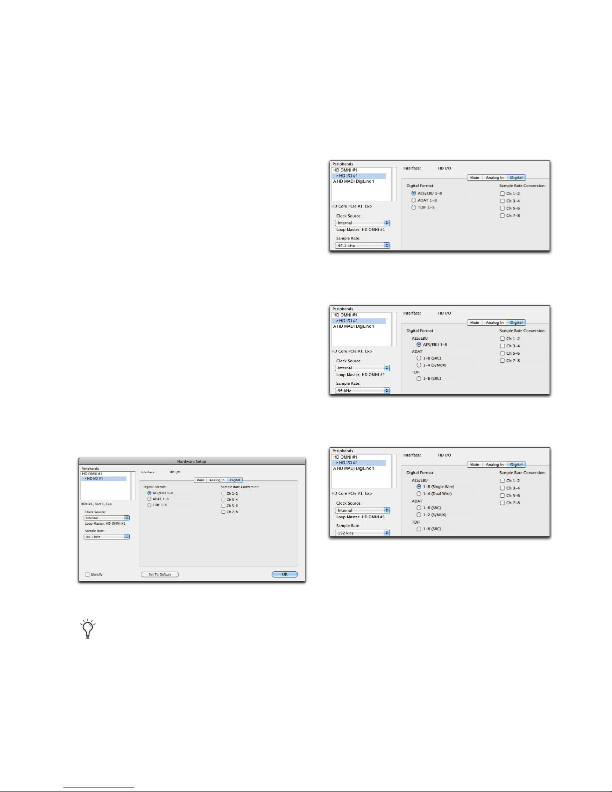
Digital Format
Select from the following digital formats for the
HD I/O Digital card. Depending on the sample
rate, different Digital Format options are available.
HD I/O Hardware Setup, Digital Format options at
44.1 kHz
HD I/O Hardware Setup, Digital Format options at
96 kHz
HD I/O Hardware Setup, Digital page
At session sample rates above 48 kHz, sample
rate conversion for the TDIF and Optical
(ADAT) inputs on the HD I/O Digital card is
automatically enabled on all eight inputs of
the selected format—unless you are using
Optical (ADAT S/MUX).
HD I/O Hardware Setup, Digital Format options at
192 kHz
Chapter 4: Configuring Pro Tools | HD I/O in Pro Tools | HD Software 27
Page 32

AES/EBU
You can select up to eight channels of AES/EBU
input depending on the sample rate. At sample
rates of 44.1 kHz to 96 kHz, the only option available is
AES/EBU 1–8
(or
AES/EBU 9–16
for the
second card, if present). At sample rates of
176.4 kHz and 192 kHz, two AES/EBU options
are available (Single Wire and Dual Wire modes).
AES/EBU 1–8
Enable this option for eight channels of AES/EBU input. This is the only option
available at sample rates of 44.1 kHz to 96 kHz.
This option is not available at higher sample rates.
AES/EBU 1–8 (Single Wire)
Enable this option for
eight channels of AES/EBU input. Sample Rate
Conversion is available for stereo pairs when Single Wire mode is selected. This option only appears at sample rates of 176.4 kHz and 192 kHz.
AES/EBU 1–4 (Dual Wire)
Enable this option for
four channels of AES/EBU input at sample rates of
176.4 kHz and 192 kHz. Sample Rate Conversion
is not available in Dual Wire mode. This option
only appears at sample rates of 176.4 kHz and
192 kHz.
1–8 (SRC)
Enable this option for eight channels of
ADAT input with automatic Sample Rate Conversion (SRC). This option only appears at sample
rates of 88.2 kHz and higher. This option is not
available at 44.1 kHz and 48 kHz.
1–4 (S/MUX)
Enable this option for four channels
of ADAT input with S/MUX (sample multiplexing). This option only appears at sample rates of
88.2 kHz and 96 kHz.
1–2 (S/MUX)
Enable this option for two channels
of ADAT input with S/MUX (sample multiplexing). This option only appears at sample rates of
176.4 kHz and 192 kHz.
TDIF
Depending on the sample rate, you can select eight
channels of TDIF (Tascam Digital Input Format)
input—
TDIF 1–8
, or
TDIF 9–16
for the second
card, if present—with or without automatic Sample Rate Conversion (SRC).
TDIF 1–8
Enable this option for eight channels of
TDIF input. This option is only available at sample
rates of 44.1 kHz and 48 kHz.
ADAT
You can select up to eight channels of ADAT input
depending on the sample rate. At 44.1 kHz and
48 kHz, the only option available is
ADAT 9–16
for the second card, if present). At
ADAT 1–8
(or
sample rates of 88.2 kHz and higher, two ADAT
options are available (SRC and S/MUX).
ADAT 1–8
Enable this option for eight channels of
ADAT input. This is the only option available at
sample rates of 44.1 kHz and 48 kHz. This option
is not available at higher sample rates.
Pro Tools | HD I/O Guide28
1–8 (SRC)
Enable this option for eight channels of
TDIF input with automatic Sample Rate Conversion. This option is only available at sample rates
of 88.2 kHz and higher.
Page 33
Sample Rate Conversion
ADAT
Sample Rate Conversion
(SRC) is independently
available for AES/EBU stereo input pairs at all
sample rates. When
Digital Format
is set to ADAT
or TDIF, SRC can only be enabled or disabled for
all channel inputs. Sample Rate Conversion on Input is only available for Digital I/O cards, it is not
available for the enclosed digital ports.
Digital outputs do
conversion.
Sample Rate Conversion adds latency to the
input signal, so you should usually disable
Sample Rate Conversion when it is not
needed.
At session sample rates above 48 kHz,
sample rate conversion for the TDIF and
Optical (ADAT) inputs on the Digital I/O
card is automatically enabled on all eight
inputs of the selected format—unless you
are using Optical (ADAT S/MUX).
not
support sample rate
For sample rates of 44.1 kHz and 48 kHz, when
Digital Format
is set to ADAT, Sample Rate Con-
version can be enabled or disabled for all inputs.
ADAT (SRC)
At sample rates higher than 48 kHz, with ADAT
(SRC) selected as the
Digital Format
, Sample Rate
Conversion is enabled automatically for all
input channels.
ADAT (S/MUX)
At sample rate higher than 48 kHz, with ADAT
(S/MUX) selected as the
Digital Format
, Sample
Rate Conversion can be enabled or disabled for all
input channels.
TDIF
For sample rates of 44.1 kHz and 48 kHz, when
Digital Format
is set to TDIF, Sample Rate Conver-
sion can be enabled or disabled for all inputs.
TDIF (SRC)
AES/EBU
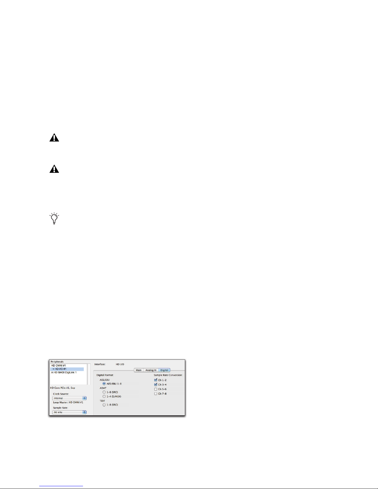
When
Digital Format
is set to AES/EBU, SRC can
be enabled or disabled for each stereo input pairs at
sample rates of 44.1 kHz to 96 kHz, and at
176.4 kHz and 192 kHz in Single Wire mode.
Sample Rate Conversion is not available for
AES/EBU at 176.4 kHz and 192 kHz in Dual Wire
mode.
SRC enabled for AES/EBU Input channels 1–2 and
3–4 at a Sample Rate of 96 kHz
Chapter 4: Configuring Pro Tools | HD I/O in Pro Tools | HD Software 29
At sample rates higher than 48 kHz, with TDIF
(SRC) selected as the
Digital Format
, Sample Rate
Conversion is enabled automatically for all
input channels.
Set To Default
The
Set To Default
factory defaults, except for the
ting in the Main page.
button sets all settings to the
Digital Format
set-
Page 34
Using Input Trims
Input Trims
Input Trims
Consider the following when connecting a mixer:
If your mixer cannot handle more than 1.5V
(RMS) inputs at +4 dBu, then you should set the
HD I/O to operate at –10 dBV line level.
If your mixer can handle up to 15.5V (RMS) inputs, or has pads or attenuators on its inputs, then
you can use the +4 dBu setting on the HD I/O.
HD I/O is calibrated at the factory for 18 dB
headroom at the +4 dBu setting.
The Input Trims below the two DB-25 connectors
on the HD I/O AD Expansion card are used to store
a calibration settings for each channel. These adjustable Input Trims are for precisely calibrating
the adjustable headroom settings for each channel.
You can adjust each Input Trim by hand with a
small screwdriver.
About Input Operating Levels
Check the manufacturer’s documentation for your
mixer, power amplifier, or effects processor to see
if it operates more comfortably at line level, in
which case consider setting the HD I/O to operate
at –10 dBV line levels and adjusting the Input
Trims.
Most manuals contain device input specifications,
including whether or not there are pads or attenuators. Refer to the manufacturer’s documentation
for your mixer or power amplifier for more information.
If you want to switch the input levels of the
HD I/O from +4 dBu to –10 dBV, you can access these parameters on a channel-by-channel basis in the Hardware Setup dialog (see
“Hardware Setup” on page 21).
Pro Tools | HD I/O Guide30
Page 35
Chapter 5: Adding or Removing I/O Cards
Pro Tools | HD I/O has four Expansion I/O bays
on the back of the unit. Depending on which version of HD I/O you purchased, one, two, or none of
these bays may be empty and available for additional I/O cards:
• 8 x 8 x 8: three bays are used and the fourth bay
is empty
• 16 x 16 Analog: all four bays are used
Removing an I/O Card
To remove an Expansion I/O card:
1
Power off and disconnect the HD I/O from your
system.
2
Make sure that the equipment is properly
grounded.
• 16 x 16 Digital: two bays are used and two are
empty
The Expansion I/O bays let you configure HD I/O
with any of the following Expansion I/O cards
(each sold separately) to increase the amount of
available I/O on the unit:
• HD I/O AD Expansion card
• HD I/O DA Expansion card
• HD I/O Digital Expansion card
It is important that you follow the guidelines in
this chapter to avoid damaging your HD I/O
or any of your I/O Expansion cards.
The factory-installed cards can be removed, if
needed, for servicing, or to swap out cards for different studio setups. If you remove any of the cards
from the HD I/O, the unit will continue to function
as long as at least one card is installed (albeit with
reduced I/O capabilities).
Legacy 192 I/O AD, DA, and Digital Option
cards are not supported with HD I/O. Any
attempt to install legacy 192 I/O cards will
void the warranty for your HD I/O.
Before handling any of the cards or internal
components of HD I/O, discharge any static
electricity by touching the outer casing of the
power supply.
3
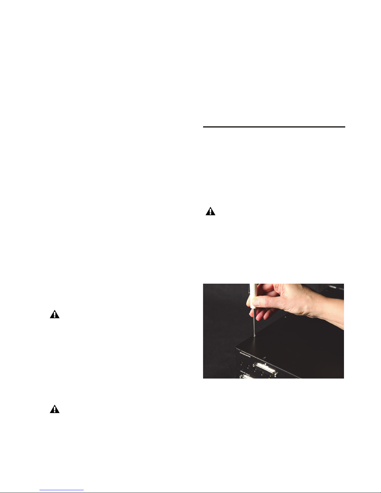
Remove all of the small Phillips-head screws
around the edges of the top cover. Put the
screws in a safe place.
Removing the top cover screws
4
Lift off the top panel of the HD I/O and set it
aside.
Chapter 5: Adding or Removing I/O Cards 31
Page 36
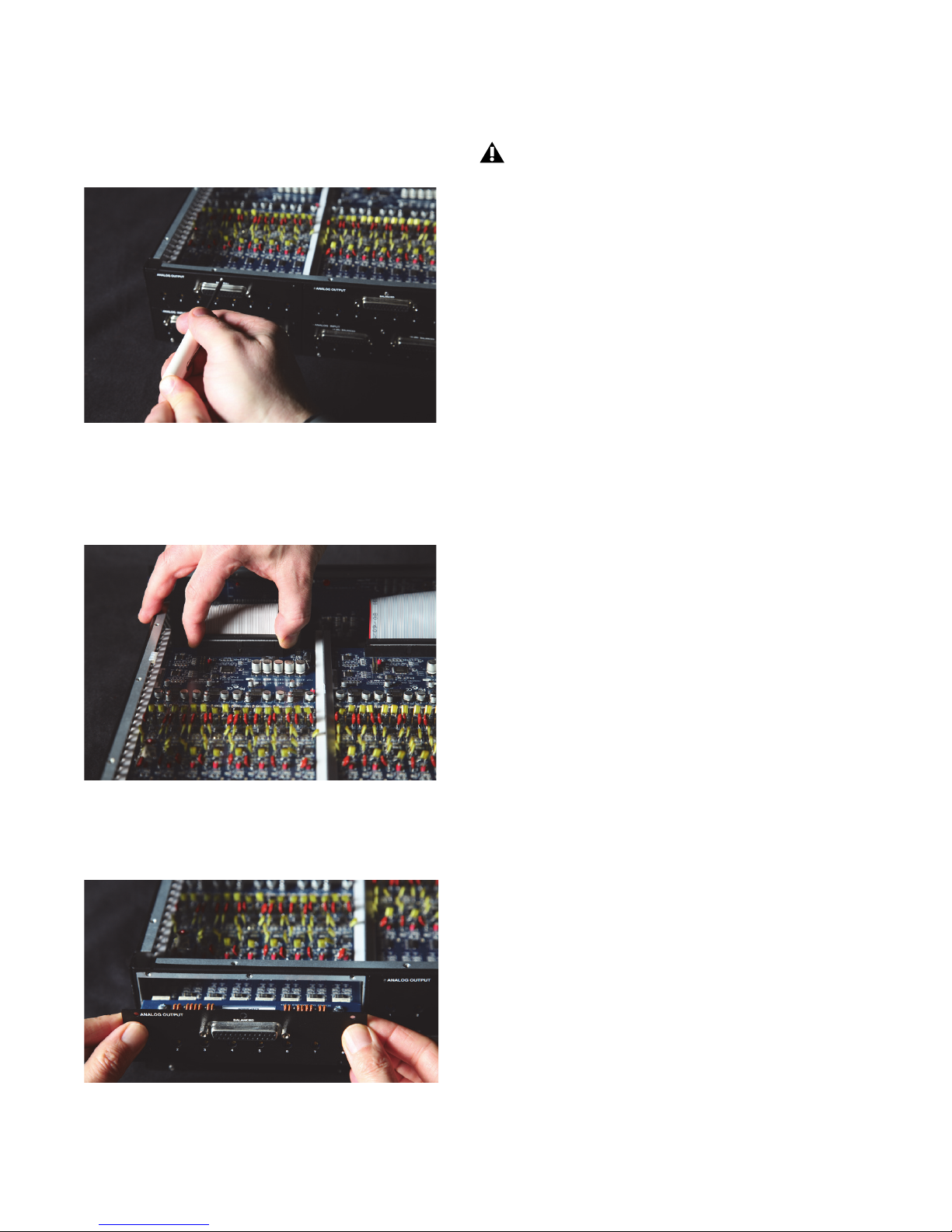
5
Remove the screws on the back panel for the
I/O card you want to remove.
When you pull a card out, pay particular attention to keeping components on the surfaces of the card from bumping into any of
the internal components or the back panel
faceplate on the HD I/O.
8
Place the card in a static-free bag and keep it in
a safe place (if you are not sending it to Avid for
service).
9
Firmly grasp the 50-pin cable connector to the
HD I/O chassis and gently pull to remove it (be
sure to keep the cable in a safe place).
Removing the screws securing an I/O card
6
Holding the 50-pin cable which connects the
card to the HD I/O chassis firmly, gently pull
the cable connector from the card’s connector.
Removing the 50-pin cable connector from an I/O card
7
Gently remove the card, pulling it straight out
from the chassis.
10
If you have a cover for the empty expansion
bay, secure the cover over the empty bay with
the screws you removed from the I/O card.
11
Replace the top cover on the HD I/O.
12
Replace the original screws.
Hardware Setup Changes After
Removing a Card
In this case, the Hardware Setup dialog will reflect
the change to the installed I/O cards. The remaining inputs and outputs will function normally.
For example, if you remove the Analog Input card,
the Analog Input tab will disappear from the Hardware Setup dialog.
You will lose the configuration of any pairs of inputs or outputs that were assigned to the card being
removed.
Removing an I/O card from the HD I/O chassis
Pro Tools | HD I/O Guide32
Page 37
Installing an Expansion I/O
Card
To install an Expansion I/O card:
1
Power off and disconnect the HD I/O from your
Pro Tools|HD system.
2
Make sure that the equipment is properly
grounded.
3
Remove all of the small Phillips-head screws
around the edges of the top cover. Put the
screws in a safe place.
4
Lift off the top of the HD I/O and set it aside.
5
If necessary, do one of the following:
• Remove the screws on the cover over the
empty bay where you want to install an Expansion card.
• Remove the currently installed I/O card that
you want to replace (see “Removing an I/O
Card” on page 31).
6
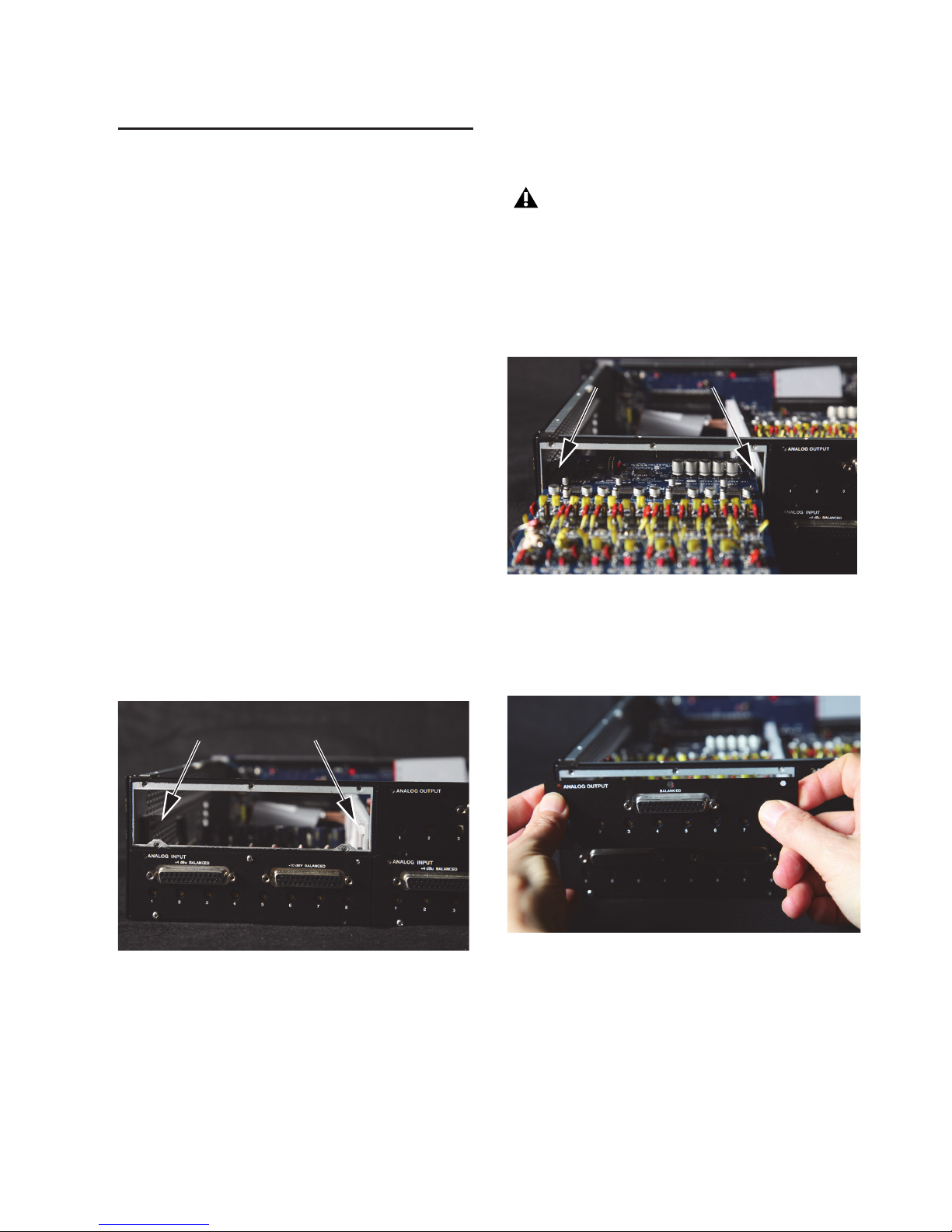
Look into the empty bay to locate the guide rails
for the card to slide in on.
7
Remove the Expansion I/O card that you want
to install from its static-free bag.
Before handling any of the cards or internal
components of HD I/O, discharge any static
electricity by touching the outer casing of the
power supply.
8
Slide the edges of the card into the guide rails on
each side of the bay.
Inserting the card into the guide rails for the empty bay
9
Gently push the card back into the bay, lifting
slightly to keep components underneath the
card from touching the back panel.
Guide rails along sides of empty bay
Lifting slightly while pushing the card back into the bay
Chapter 5: Adding or Removing I/O Cards 33
Page 38
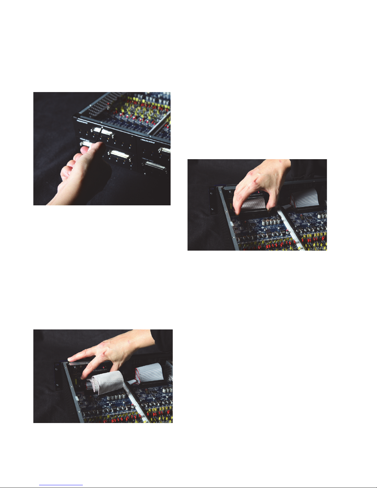
10
Secure the I/O card to the back panel of the
HD I/O chassis with the same screws you removed from the either the empty bay cover or
from the I/O card you previously removed.
Securing the I/O card to the back panel of the HD I/O
11
Locate the raised ridge in the middle of the connector on one end of the 50-pin cable that connects the I/O card to the HD I/O chassis. This
ridge is only on one side of the connector, and
there is a matching groove on only one side of
the 50-pin connector on the chassis.
13
Locate the raised ridge in the middle of the connector on the other end of the 50-pin cable that
connects the I/O card to the HD I/O chassis.
This ridge is only on one side of the connector,
and there is a matching groove on only one side
of the 50-pin connector on the card.
14
Gently push the cable connector into the card’s
connector. The ridge on the cable connector
must line directly into the groove on the card
connector. Be very careful not to bend any of
the pins or to over-stress the card.
Pressing the 50-pin cable connector into the card
15
Replace the top cover on the HD I/O.
12
Gently push the cable connector into the chassis’ connector. The ridge on the cable connector
must line directly into the groove on the chassis
connector. Be very careful not to bend any of
the pins.
Connecting the 50-pin cable to the HD I/O chassis
Pro Tools | HD I/O Guide34
16
Replace the original screws.
17
Reconnect the HD I/O to your system.
18
Power on the HD I/O.
19
When you power on the unit, verify that the
LED ring around the power switch lights orange.
20
Start up the computer.
21
When you start the computer, verify that the
power ring turns from orange to green. (If this
does not occur, see “Troubleshooting” on
page 35.)
22
Launch Pro Tools.
Page 39

23
Open the Hardware Setup dialog to confirm that
the new card is recognized:
• If you installed a Digital Expansion card, you
should see a new tab called “Digital 9–16.”
• If you installed an AD Expansion card, you
should see a new tab called “Analog In
9–16.”
24
If the new card does not appear in the Hardware
Setup dialog, power down, check the seating of
the card, and recheck the cable connections inside the HD I/O.
Hardware Setup Changes After Adding
a Card
Any additional inputs and outputs provided by the
new card will appear in the Hardware Setup dialog,
with the same controls and parameters as for the
original card of the same type.
Troubleshooting
If the power ring does not turn from orange to
green when you boot the computer, check the following:
• Make sure the DigiLink Mini cable is connected
to the Primary port on the back of the unit.
• Make sure that the 50-pin cables used to connect
the installed I/O cards to the chassis are firmly
connected.
For example, if you add an Analog Input card to
the original three cards, a second Analog Input tab
will appear in the Hardware Setup dialog. You can
route these new inputs (which will in this case be
called Analog Inputs 9–16) with the same controls
and parameters as the factory-installed version of
the card.
Whenever a card is added or removed from a
HD I/O, the routing in the Hardware Setup
dialog reverts to the default assignments. If
you have complex routing and or mirroring in
place, note the assignments and reassign the
inputs and outputs after the new card has
been properly identified.
Chapter 5: Adding or Removing I/O Cards 35
Page 40

Pro Tools | HD I/O Guide36
Page 41
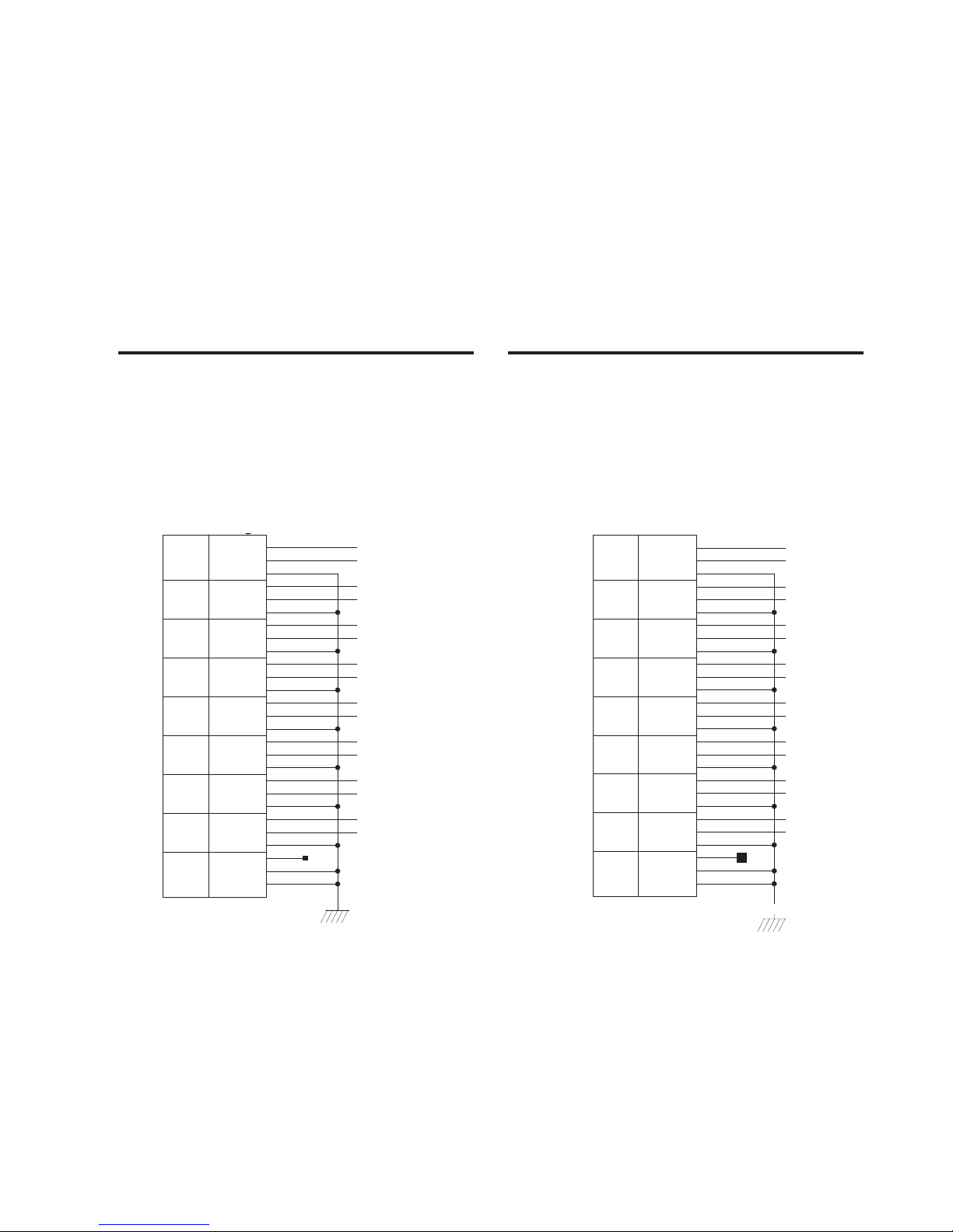
Chapter 6: Pinout Diagrams for the DB-25
MH2
CH1_COLD
CH1_HOT
CH2_GND
CH2_COLD
CH3_GND
CH3_HOT
CH3_COLD
CH4_GND
CH4_HOT
CH4_COLD
CH8_COLD
CH7_COLD
CH7_HOT
CH7_GND
CH6_COLD
CH6_HOT
CH6_GND
CH5_GND
CH5_HOT
CH5_COLD
CH8_GND
NC_1
CH1_GND
CH2_HOT
CH8_HOT
MH1
1
8
7
6
5
4
3
2
27
12
24
11
23
22
21
9
8
7
20
14
3
15
16
17
4
5
19
18
6
2
13
25
10
1
26
MH2
CH1_COLD
CH1_HOT
CH2_GND
CH2_COLD
CH3_GND
CH3_HOT
CH3_COLD
CH4_GND
CH4_HOT
CH4_COLD
CH8_COLD
CH7_COLD
CH7_HOT
CH7_GND
CH6_COLD
CH6_HOT
CH6_GND
CH5_GND
CH5_HOT
CH5_COLD
CH8_GND
NC_1
CH1_GND
CH2_HOT
CH8_HOT
MH1
1
8
7
6
5
4
3
2
27
12
24
11
23
22
21
9
8
7
20
14
3
15
16
17
4
5
19
18
6
2
13
25
10
1
26
Connectors
Analog Output DB-25 Analog Input (+4 dBu) DB-25
Chapter 6: Pinout Diagrams for the DB-25 Connectors 37
Page 42
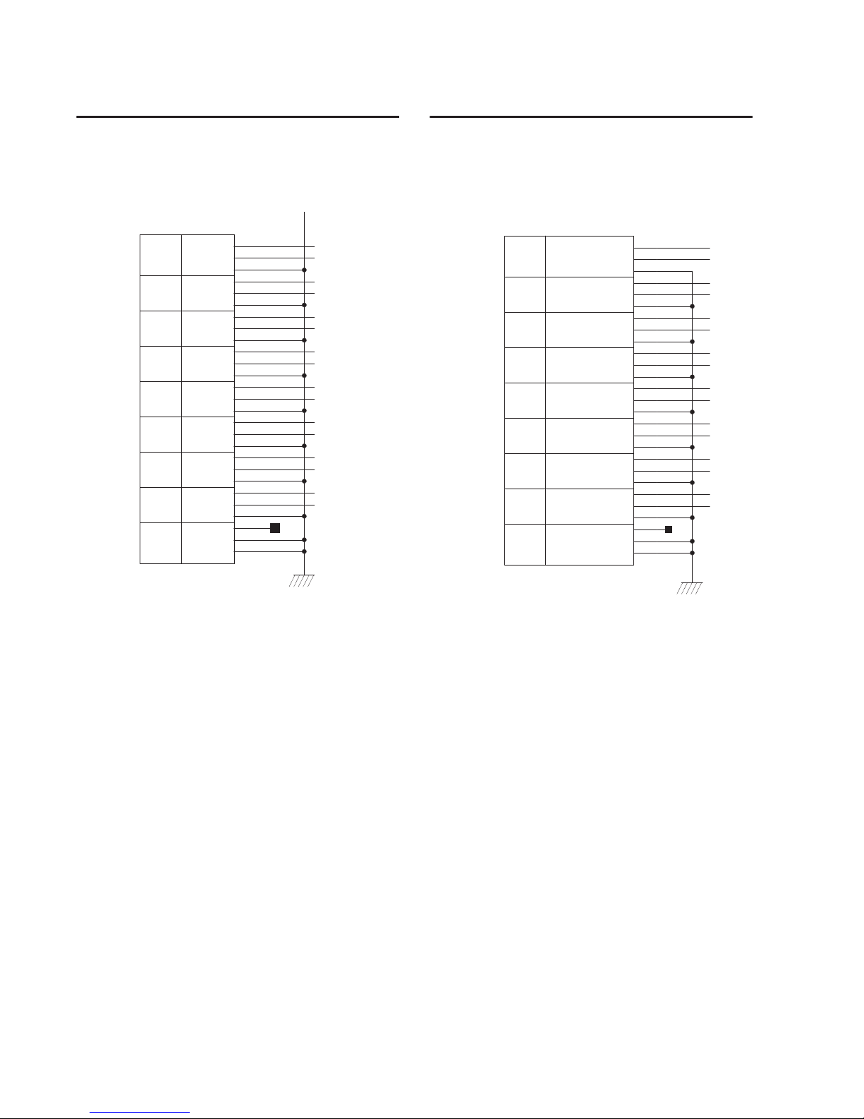
Analog Input (–10dBV) DB-25 AES/EBU DB-25
MH2
CH1_COLD
CH1_HOT
CH2_GND
CH2_COLD
CH3_GND
CH3_HOT
CH3_COLD
CH4_GND
CH4_HOT
CH4_COLD
CH8_COLD
CH7_COLD
CH7_HOT
CH7_GND
CH6_COLD
CH6_HOT
CH6_GND
CH5_GND
CH5_HOT
CH5_COLD
CH8_GND
NC_1
CH1_GND
CH2_HOT
CH8_HOT
MH1
1
8
7
6
5
4
3
2
27
12
24
11
23
22
21
9
8
7
20
14
3
15
16
17
4
5
19
18
6
2
13
25
10
1
26
MH2
CH12_RCV_COLD
CH12_RCV_HOT
CH34_RCV_GND
CH34_RCV_COLD
CH56_RCV_GND
CH56_RCV_HOT
CH56_RCV_COLD
CH78_RCV_GND
CH78_RCV_HOT
CH78_RCV_COLD
CH78_XMT_COLD
CH56_XMT_COLD
CH56_XMT_HOT
CH56_XMT_GND
CH34_XMT_COLD
CH34_XMT_HOT
CH34_XMT_GND
CH12_XMT_GND
CH12_XMT_HOT
CH12_XMT_COLD
CH78_XMT_GND
NC_1
CH12_RCV_GND
CH34_RCV_HOT
CH78_XMT_HOT
MH1
XMT
XMT
XMT
7-8
5-6
3-4
RCV
RCV
RCV
1-2
RCV
3-4
5-6
7-8
1-2
XMT
27
12
24
11
23
22
21
9
8
7
20
14
3
15
16
17
4
5
19
18
6
2
13
25
10
1
26
Pro Tools | HD I/O Guide38
Page 43
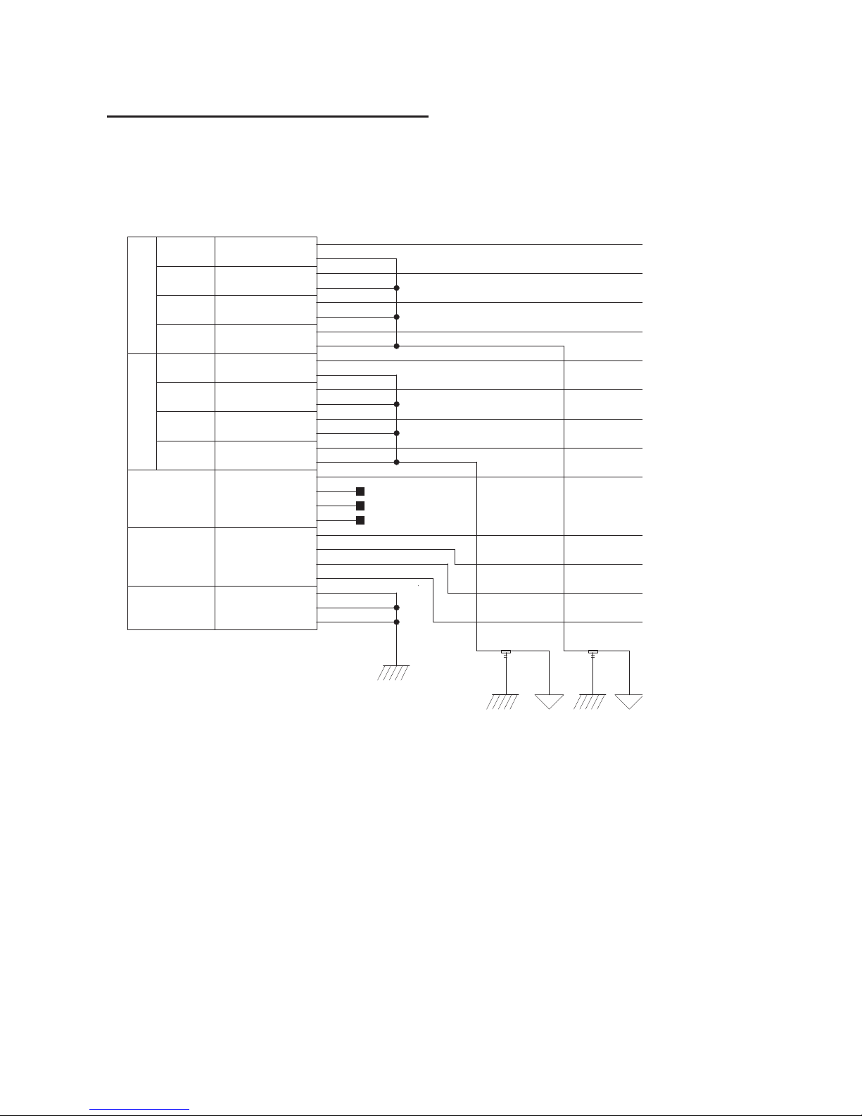
TDIF DB-25
GND_AGND_A
GND_C
22PF22PF
GND_C
MH2
CH12_RCV_DATA
GND3
CH56_RCV_DATA
CH12_XMT_DATA
CH78_RCV_DATA
GND4
GND6
GND5
CH34_XMT_DATA
XMT_FS1
RCV_FS0
RCV_FS1
XMT_LRCK
RCV_LRCK
RCV_EMPHASIS
CH56_XMT_DATA
GND7
XMT_FS0
CH34_RCV_DATA
GND2
XMT_EMPHASIS
MH1
DB25F_RA_TDIF
GND1
CH78_XMT_DATA
GND8
GND9
7-8
CLK+CTRL
1-2
3-4
5-6
1-2
3-4
5-6
RCV DATAXMT DATA
RCV
CLK+CTRL
XMT
7-8
GND_C
27
13
23
11
1
10
22
15
14
2
19
20
8
5
9
21
3
16
6
12
24
18
26
25
4
17
7
NC=
NC=
NC=
FB30 FB31
Chapter 6: Pinout Diagrams for the DB-25 Connectors 39
Page 44

Pro Tools | HD I/O Guide40
Page 45

Chapter 7: HD I/O Calibration Mode
Instructions
Before you use Pro Tools | HD I/O, you may want
to calibrate its input and output levels to the level
of your mixing console.
The HD I/O has +4 dBu and –10 dBV inputs, and
+4 dBu outputs, each with its own trim pot for
proper calibration.
The HD I/O is factory-calibrated so that its +4 dBu
input operating level is set for 18 dB headroom
above +4 dBu (maximum input/output +22 dBu).
If you need to recalibrate your HD I/O or other
components of your studio, you can use the alignment procedure described in this chapter.
About Calibration
Calibrating levels on a digital recording device is
different from calibrating levels on an analog recording device. Unlike analog devices, most digital devices do not have a standard “0 VU” level
setting that corresponds to nominal input and output levels. Instead, with an interface such as the
HD I/O, the meters are calibrated in decibels below
peak or dBFS (dB full scale)—digital clipping
level.
Headroom
The concept of headroom is slightly different for
analog and digital devices.
Analog
amount of headroom above 0 VU. If you send a
signal above 0 VU to an analog recorder, you still
have a margin of headroom, and if tape saturation
occurs, it does so fairly gracefully, giving the audio a compressed sound that some find desirable.
Digital
exceed the dynamic range of the input or dBFS (dB
full scale). When a signal exceeds the maximum
input level for a digital device, clipping occurs,
causing digital distortion, which is harsh and usually undesirable.
Most analog devices allow for a certain
Digital devices do not allow for signals that
The Calibration Process
Analog
device to a mixing console’s output level, you
would typically send a 1 kHz tone at 0 VU from
the console to the analog deck and align the recording deck’s meters to read 0 VU.
Digital
HD I/O, in order to allow for headroom, you must
align a 0 VU tone from the console to a value less
than zero (or below dB full scale [–x dBFS]) on
the HD I/O, by exactly the amount of headroom
that you want.
To calibrate the input level of an analog
With a digital recording device such as the
Chapter 7: HD I/O Calibration Mode Instructions 41
Page 46
For example, to have 12 dB of headroom above
0 VU with the HD I/O, you must align the incoming 0 VU 1kHz tone to a level of –12 dBFS. For
18 dB of headroom, you would align it to
–18 dBFS. (Since it is assumed that you are using
the HD I/O with a +4 dBu device or console, a
0 VU signal level coming out of the device or console is actually equivalent to a nominal +4 dBu
level signal.)
Calibrating the HD I/O
To calibrate your HD I/O, use one of the HD I/O
calibration sessions included with Pro Tools (located in the Pro Tools Utilities/Calibration Mode
Session/HD IO Calibration Session folder). You
can use these sessions as is and change the input
and output assignments for more HD I/O channels
or use it as a template to make your own calibration
session.
The following instructions show how to create a
calibration session from scratch.
If your system includes one or more EUCON
controllers, be sure to disable “Auto-bank to
selected track” in EuControl software before
enabling Pro Tools Calibration Mode to ensure that faders remain silent. To make sure
“Auto-bank to select track” is not enabled,
open the EuControl Settings window, click to
go to the General tab, and verify the setting is
not enabled. If necessary, click to disable
“Auto-bank to selected track.” After exiting
Calibration Mode, be sure to re-enable the
“Auto-bank to selected track” setting (if necessary).
To create a session for calibrating your HD I/O:
1
Launch Pro Tools and create a new session.
2
Choose
eration
3
Enter the desired Calibration Reference Level
Setup > Preferences
tab.
and click the
value in dB. A level of –18 dB is typical. (It is
not necessary to type a minus sign here.)
4
Click OK.
5
Create a new mono audio track by choosing
Track > New
6
Insert the Signal Generator plug-in on the track.
7
Set the Signal Generator plug-in output level.
.
This should be the same value you entered as
the Calibration Reference Level (such as
–18 dB).
8
Set the Signal Generator frequency to 1000 Hz.
1000 Hz is typical, but any frequency will work.
Other typical values are 250 Hz and 500 Hz.
9
Set the Signal Generator signal waveform to
Sine.
10
Route the track’s output to Bus 1. In the calibration template, Bus 1 has been renamed to “1k
Tone.”
11
Create a mono Auxiliary Input track for each
HD I/O output you want to calibrate. Set the
output assignment for each of these Auxiliary
Inputs to its respective I/O output.
12
Set the input of each Auxiliary Input track to
Bus 1, or 1k Tone for the template session.
Op-
Turn down your monitoring system before
beginning calibration. The Signal Generator
plug-in emits a continuous signal when inserted on a track.
Pro Tools | HD I/O Guide42
Page 47

13
Create an additional mono Auxiliary Input track
for each input you want to calibrate. Set the input assignment for each of these Auxiliary Inputs to its respective I/O input. Then set the
output of each of these Auxiliary Inputs to an
unused bus pair (for example Bus 3–4). In the
template session the bus names are Null and
Out. This makes sure feedback doesn’t occur
when monitoring main outputs 1–2.
14
Connect an external VU meter to each of the I/O
outputs in turn. (One at a time as you calibrate.)
15
Set all Pro Tools track faders to their default of
0 dB by Option-clicking (Mac) or Alt-clicking
(Windows) any fader.
16
Adjust the I/O output level trim pot with a
small, flat-head screwdriver to align the outputs
to read “0 VU” on the external VU meter. We
recommend using a tweaker tool with a recessed flat-head surrounded by a plastic tube to
hold the trim pot. Tweakers can usually be
found at electronic supply stores.
3
Adjust the HD I/O input level trim pots with the
same small flat-head screwdriver or tweaker. It
is best to calibrate the inputs with the back of
the HD I/O facing you and the Pro Tools screen
well in sight. If you cannot see the Pro Tools
screen, consider asking another person to assist
you with the input calibration. When the level is
properly matched, the track name will stop
flashing and the peak volume indicator will indicate your headroom value (the default is
“–18.0”).
The Automatch indicator arrows on each track
show the direction of adjustment required for
alignment:
• When the incoming level is higher than the
reference level, the down arrow will appear
lit (blue). In this case, trim the I/O input level
down.
• When the incoming level is lower than the
reference level the up arrow will appear lit
(red). In this case, trim the I/O input level up.
To calibrate the HD I/O inputs:
1
Connect the HD I/O outputs to a bank of
HD I/O inputs by doing either of the following:
• Use a DB-25 to DB-25 straight through cable.
• Interconnect the XLR ends of DB-25-to-XLR
together.
2
In Pro Tools, select
Options > Calibration Mode
The names of all uncalibrated tracks begin to flash.
In addition, the track volume indicator of each
Auxiliary Input track receiving an external input
signal now displays the reference level coming
from the calibrated output (default is –18 dB).
When you have properly aligned the incoming
peak signal levels to match the calibration reference level, both Automatch indicator arrows will
light: the up arrow red and the down arrow blue.
Above the fader is a peak volume indicator. This
indicator will show the dB level above and below
your chosen headroom value. If the peak indicator
is showing –19.1, you are –1.1 dB below a head-
.
room value of –18 dB. If the display is showing
–16.5, you are +1.5 dB above your headroom value
of –18 dB.
4
When you have finished, deselect
Calibration Mode
.
Options >
Chapter 7: HD I/O Calibration Mode Instructions 43
Page 48
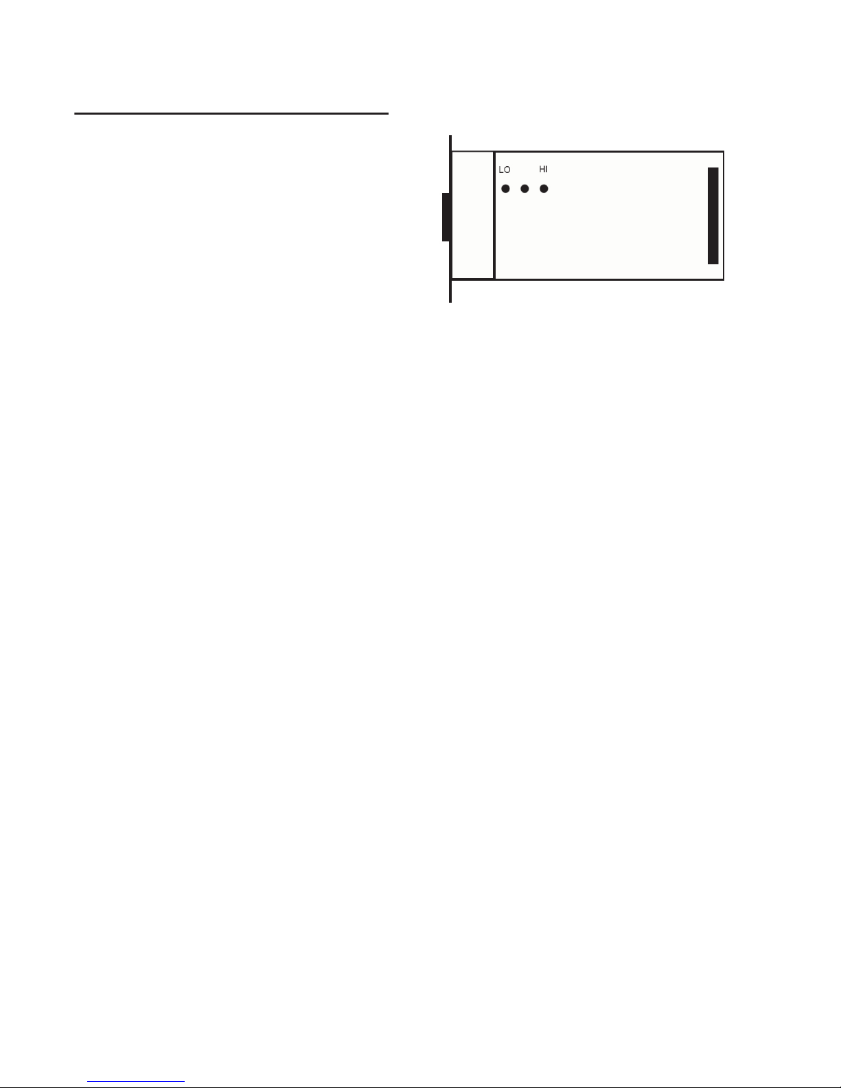
Switching Jumpers on the
Analog Output Card
Each Analog Output card for HD I/O provides a
jumper for each of the eight channels of output on
the card to switch between a Hi and Lo output setting. The default setting for each jumper is Hi. This
is what you want for working with professional
gear that operates at +4 dBu levels.
However, if you are working with –10 dBV gear,
you can switch the jumper on Analog Output card
(on a channel-by-channel basis) from the default
Hi position to Lo for a –6 dB pad. You can then adjust the Trim pot for the corresponding output
channels by an additional –4 dB to accommodate
–10 dBV gear.
To switch the jumpers for output channels on an
Output card:
1
Remove the Output card from the HD I/O chassis (as described in Chapter 5, “Adding or Removing I/O Cards”).
2
Place the card on a stable, static free surface.
3
Using tweezers or a pair of needle nose pliers,
gently remove the jumper for each output channel that you want to modify.
4
Gently, but firmly, replace the jumper in the
position that you want for Hi or Lo output:
Pin orientation on Output card
5
Replace the Output card in the HD I/O chassis
(as described in Chapter 5, “Adding or Removing I/O Cards”).
• Place the jumper so that it connects the middle pin and the back pin (furthest from the
DB-25 connector) for the Hi setting (this is
the factory default setting).
• Place the jumper so that it connects the middle pin and the front pin (closest to the DB-25
connector) for the Lo setting (–6 dB pad).
Pro Tools | HD I/O Guide44
Page 49
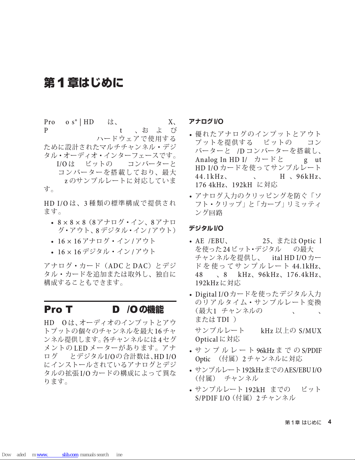
第
章はじめに
1
Pro Tools® | HD I/O
ProTools®|HDNative
Pro Tools® | HD
ために設計されたマルチチャンネル・デジ
タル・オーディオ・インターフェースです。
HD I/Oは24
コンバーターを搭載しており、最大
D/A
192kHz
す。
HDI/O
ます。
ビットの
のサンプルレートに対応していま
は、3種類の標準構成で提供され
•8 × 8 × 8(8
グ・アウト、8デジタル・イン/アウト)
•16 × 16
•16 × 16
アナログ・カ ード(
タル・カードを追加または取外し、独自に
構成することもできます。
アナログ・イン/アウト
デジタル・イン/アウト
は、
Pro Tools® | HDX
、お よ び
ハードウェアで使用する
コンバーターと
A/D
アナログ・イン、8アナロ
ADCとDAC
)とデ ジ
、
アナログ
優れたアナログのインプットとアウト
•
プットを提供する24ビットの
バーターと
Analog In HD I/O
HD I/O
I/O
D/A
コンバーターを搭載し、
A/D
カードと
カードを使ってサンプルレート
Analog Out
44.1kHz、48kHz、88.2kHz、96kHz
176.4kHz、192kHz
アナログ入力のクリッピングを防ぐ「ソ
•
フト・クリップ」と「カーブ」リミッティ
ング回路
デジタル
I/O
•AES/EBU、TDIF DB-25
を使った24ビット・デジタル
チャンネルを提供し、
ドを使ってサンプルレート
に対応
、または
の最大
I/O
Digital HD I/O
44.1kHz
Optical
48kHz、88.2kHz、96kHz、176.4kHz
192kHz
に対応
コン
、
16
カー
、
、
Pro Tools | HDI/O
HD I/O
トプットの個々のチャンネ ルを最大16チャ
ンネル提供します。各チャンネルには4セグ
メントの
ログ
にインストールされているアナログとデジ
タルの拡張
ります。
は、オーディオのインプットとアウ
メーターがあります。アナ
LED
とデジタル
I/O
カードの構成によって異な
I/O
の合計数は、
I/O
の機能
HD I/O
• Digital I/O
のリアルタイム・サンプルレート変換
(最大16チャンネルの
または
サンプルレート
•
Optical
サンプルレート
•
Optical
サンプルレート
•
(付属)2チャンネル
サンプルレート
•
S/PDIF I/O
カードを使ったデジタル入力
AES/EBU、Optical
)
TDIF
88.2kHz
に対応
96kHz
(付属)2チャンネルに対応
192kHz
192kHz
(付属)2チャンネル
以上の
までの
までの
AES/EBU I/O
までの24ビット
第1章 はじめに
S/MUX
S/PDIF
、
45
Page 50
同期
追加の
•
機器を接続するための
プットとアウトプット
•HDI/O
するための外部クロック・インプットと
アウトプット
拡張性
オプションの追加
•
たはデジタル
システムのインプットおよびアウトプッ
•
トをさらに拡張する複数の
ディオ・インターフェースの同時使用
Avid HD
を外部ワードクロック機器と同期
インターフェースや周辺
のイン
I/O
Loop Sync
カードでアナログま
I/O
を拡張
Avid HD
内容
•ProTools|HDI/O
ターフェース
•AC
•
電源ケーブル
DigiLink Mini
ケーブル(
オーディオ・イン
0.46m(18
インチ))
オー
システム要件と互換性
では、互換性を含め、ハードウェアや
Avid
ソフトウェアについて一定の基準で動作確
認作業を行っていますが。
完全なシステム要件および要件を満たした
コンピューター、オペレーティング・シス
テム、ハード・ドライブ、サード パーティー
製機器のリストについては以下のサイトを
ご覧ください。
www.avid.com/compatibility
登録
同梱のオンライン登録情報カードの説明に
従って、購入した製品をオンラインでご登
録ください。登録されますと以下のサービス
を受けることができます。
テクニカルサポートに関する情報
•
ソフトウェアアップデートおよびアッ
•
プグレードの通知
• DigiLink Mini
•BNC
ケーブル(
•ProToolsHD I/O
安全にお使いいただくためのガイド
•
オンライン登録情報カード
•
アダプター
0.46m(18
ガイド
インチ))
ハードウェアの限定保証
•
ハードウェアの保証
ご使用のハードウェアの保証は、オンライ
ン登録情報カードに記載されています。
46
Pro Tools | HD I/O
ガイド
Page 51
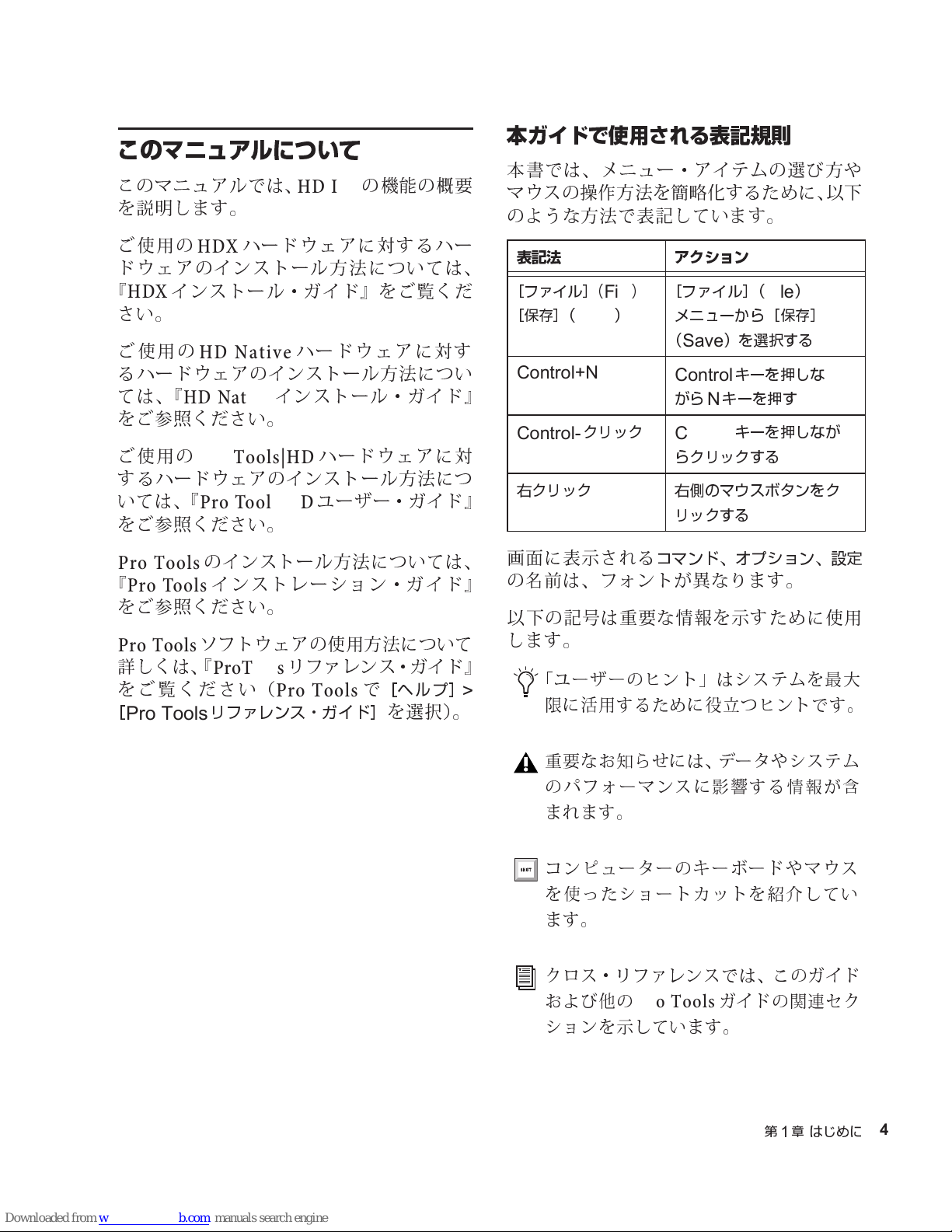
このマニュアルについて
このマニュアルでは、
を説明します。
HD I/O
の機能の概要
本ガイドで使用される表記規則
本書では、メニュー・アイテムの選び方や
マウスの操作方法を簡略化するために、以下
のような方法で表記しています。
ご使用の
ハードウェアに対するハー
HDX
ドウェアのインストール方法 については、
『
インストール・ガイド』をご覧くだ
HDX
さい。
ご使用の
HD Native
ハードウェアに対す
るハードウェアのインストール方法につい
ては、『
HD Native
インストール・ガイド』
をご参照ください。
ご使用の
Pro Tools|HD
ハードウェアに対
するハードウェアのインストール方法につ
いては、『
Pro Tools|HD
ユーザー・ガイド』
をご参照ください。
Pro Tools
『
Pro Tools
のインストール方法につ いては、
インストレーション・ガイド』
をご参照ください。
Pro Tools
詳しくは、『
をご覧ください(
[
Pro Tools
ソフトウェアの使用方法について
ProTools
リファレンス・ガイド]
リファレンス・ガイド』
で
Pro Tools
[ヘルプ]
を選択)。
>
表記法 アクション
[ファイル]
[保存](
Control+N
Control-
右クリック
画面に表示される
(
File)>
)
Save
クリック
[ファイル](
メニューから[保存]
Save
N
)を選択する
キーを押しな
キーを押す
キーを押しなが
(
Control
がら
Control
らクリックする
右側のマウスボタンをク
リックする
コマンド、オプション、設定
File
)
の名前は、フォントが異なります。
以下の記号は重要な情報を示すために使用
します。
「ユーザーのヒント」はシステムを最大
限に活用するために役立つヒントです。
重要なお知らせには、データやシステム
のパフォーマンスに影響する情報 が含
まれます。
コンピューターのキーボードやマウス
を使ったショートカットを紹介してい
ます。
クロス
および他の
ションを示しています。
・
リファレンスでは、このガイド
ProTools
ガイドの関連セク
第1章 はじめに
47
Page 52
www.avid.com
について
のウェブサイト(
Avid
ProTools
めの最良のオンライン情報源です。次に利
用可能なサービスと機能の一部をご紹介し
ます。
製品登録
できます。
サポートとダウンロード
Success
スします。ソフトウェア・アップデートや最
新のオンライン・マニュアルのダウンロード、
システム要件の互換性ガイドの閲覧、オンラ
イン知識ベースの検索、オン ライン・ナレッ
ジベースの検索、そしてユーザー会議での 世
界規模の
が可能です。
トレーニングと教育
コースを通じて自己学習を行ったり、公認 の
ProTools
れる授業について検索することができます。
システムを最大限に活 用するた
購入した製品をオンラインで登録
(テクニカル・サポート)にアクセ
ProTools
オンラインで利用可能な
トレーニング・センターで実施さ
www.avid.com
Avid Customer
コミュニティへの参加
)は 、
製品と開発者
ウェアのデモ版のダウンロード、デベロッ
プメント・パートナーとそのプラグイン、
アプリケーション、ハードウェアに関する
情報をご覧いただけます。
ニュースとイベント
得
したり、
したりすることができます。
48
Pro Tools | HD I/O
製品に関する情報:ソフト
Avid
の最新ニュースを取
Avid
ProTools
デモにサイン・アップ
ガイド
Page 53
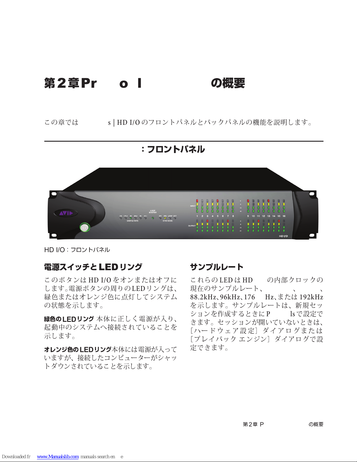
第
2
章
Pro Tools | HD I/O
の概要
この章では
Pro Tools | HD I/O
Pro Tools | HD I/O
HD I/O
電源スイッチと
このボタンは
します。電源ボタンの周りの
緑色
の
緑色の
起動中
示します。
オレンジ色の
いますが、接続したコンピューターがシャッ
トダウンされていることを示します。
:フロントパネル
LED
HDI/O
またはオレンジ色に
状態
を示します。
リング
LED
のシステムへ接続されていることを
本体に正しく電源が入り、
リング
LED
リング
をオンまたはオフに
点灯
本体には電源が入って
のフロントパネルとバックパネルの機能を 説明します。
:フロントパネル
リングは、
LED
してシステム
サンプルレート
これらの
現在
LEDはHD I/O
のサンプルレート、
88.2kHz、96kHz、176.4kHz
を示します。サンプルレートは、新規セッ
ションを作成するときに
きます。セッションが開いていないときは、
[
ハードウェア設定]ダイアログまたは
エ
[
プレイバック
定できます。
ンジン]ダイアログで設
の内部クロックの
44.1kHz、48kHz
、または
Pro Tools
192kHz
で設定で
、
第2章
Pro Tools | HD I/O
の概要
49
Page 54
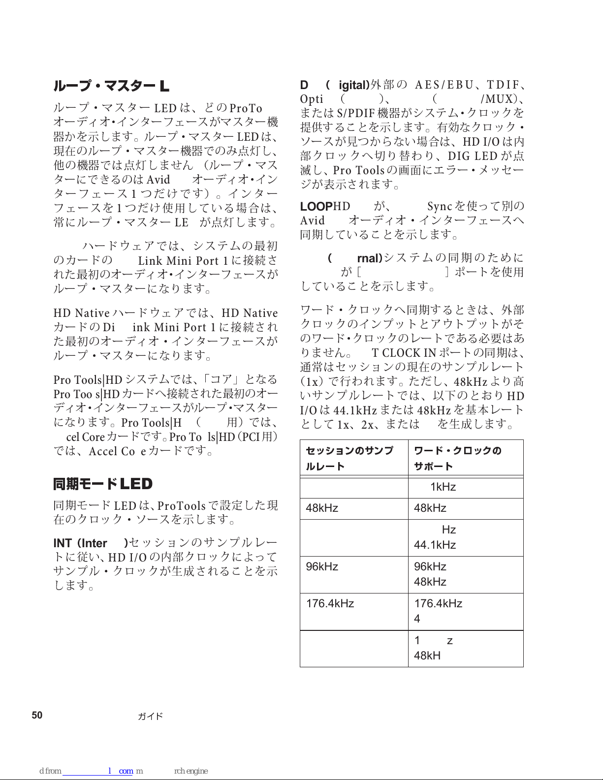
ループ・マスター
ループ・マスタ ー
オーディオ・インターフェースがマスター機
器かを示します。ループ・マスター
現在
のループ・マスター機器での
他
の機器では
ターにできるのは
ターフェース1つだけです)。インター
フェースを1つだけ使用している場合は、
常
にルー プ・マスター
ハードウェアでは、システムの最
HDX
のカードの
れた最初のオーディオ・インターフェースが
ループ・マスターになります。
点灯
DigiLink Mini Port 1
LED
は、どの
LED
しま
せん (ルー プ・マ ス
Avid HD
オーディオ・イン
が
LED
点灯
ProTools
は、
LED
み点灯
に接続さ
し、
します。
初
DIG(Digital
外部の
AES/EBU、TDIF
)
Optical(ADAT)、Optical(ADAT S/MUX
または
提供することを示します。
ソースが見つからない場合は、
部クロックへ切り
滅
ジが表示されます。
LOOP
し、
Pro Tools
HDI/O
S/PDIF
Avid HD
同期していることを示します。
EXT(External
HD I/O
していることを示します。
が
機器がシステム・クロック を
有効
なクロック・
HD I/O
替わ
り、
DIG LED
の画面にエラー・メッセ ー
が、
Loop Sync
オーディオ・インターフェースへ
)
システムの同期のために
[
EXT CLOCK IN
を使って別の
]
ポートを使用
は
が
、
)、
内
点
HD Native
カードの
た最初のオーディオ・インターフェースが
ループ・マスターになります。
Pro Tools|HD
Pro Tools|HD
ディオ・インターフェースがループ・マスター
になります。
Accel Core
では、
同期モード
同期モード
在
のクロック・ソースを示します。
INT(Internal
トに従い、
サンプル・クロックが生成されることを示
します。
ハードウェアでは、
DigiLink Mini Port 1
システムでは、「コア」となる
カードへ接続された最初のオー
Pro Tools|HD(PCIe
カードです。
Accel Core
Pro Tools|HD(PCI
カードです。
LED
は、
LED
)
HD I/O
ProTools
セッションのサンプルレー
の内部クロックによって
HD Native
に接続され
用)では 、
で設定した
用)
現
ワード・クロックへ同期するときは、外部
クロックのインプットとアウトプットがそ
のワード・クロックのレートである必要はあ
りま
せん
。
EXT CLOCK IN
通常はセッションの
(1x)で 行われます。ただし、
いサンプルレートでは、以下のとおり
は
I/O
として1x、2x、または4xを生成します。
44.1kHz
セッションのサンプ
ルレート
44.1kHz 44.1kHz
48kHz 48kHz
88.2kHz 88.2kHz
96kHz 96kHz
現在
または
ポートの同期は、
のサンプルレート
48kHz
48kHz
ワード・クロックの
サポート
44.1kHz
48kHz
を基本レート
より
高
HD
50
Pro Tools | HD I/O
ガイド
176.4kHz 176.4kHz
44.1kHz
192kHz 192kHz
48kHz
Page 55
メーター
これらの4セグメントの
は、16チャン
LED
ネルのそれぞれの信号レベルを示します。
上の段のメーターがインプット・レベルを
示し、下の段のメーターがアウトプッ ト・
レベルを示します。これらのメーターは、
それぞれ
–42dB、–18dB、–6dB、0dB
でキャ
リブレートされます。
は
必ず
0dB
ま
せん。信
かどうか
しもクリッピングではあり
号がクリッピングしている
は、
Pro Tools
の画面のメー
ターで確認してください。
第2章
Pro Tools | HD I/O
の概要
51
Page 56
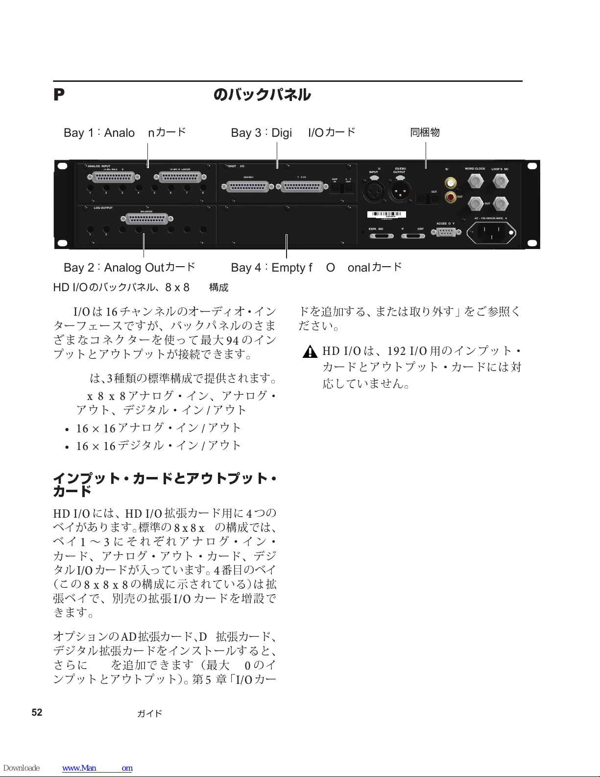
Pro Tools | HD I/O
964530300294856
WORD CLOCK
LOOP SYNC
PRIMARY PORT
EXPANSION PORT
IN
OUT
AC ~ 100-240V;50-60HZ; A
S/PDIF
IN
OUT
AES/EBU
INPUT
AES/EBU
OUTPUT
OPTICAL
IN
OUT
ACCESSORY
1
2
3
4
5
6
7
8
ANALOG INPUT
+4 dBu BALANCED
-10 dBV BALANCED
1
2
3
4
5
6
7
8
ANALOG OUTPUT
BALANCED
DIGITAL I/O
AES/EBU
ADAT
IN
TDIF I/O
ADAT
OUT
Bay 2:Analog Out
カード
Bay 1:Analog In
カード
Bay 3:Digital I/O
カード
Bay 4:Empty for Optional
カード
同梱物
のバックパネル
HD I/O
のバックパネル、
HD I/Oは16
8 x 8 x 8
チャンネルのオーディオ・イン
構成
ターフェースですが、バックパネルのさま
ざ
まなコネクターを使っ て最大94のイン
プットとアウトプットが接続できます。
HDI/O
は、3種類の標準構成で提供されます。
• 8 x 8 x 8
アナログ・イン、アナログ・
アウト、デジタル・イン/アウト
•16 × 16
•16 × 16
アナログ・イン/アウト
デジタル・イン/アウト
インプット・カードとアウトプット・
カード
HD I/O
には、
HD I/O
ベイがあります。標準の
ベイ1〜3にそれぞれアナログ・イン・
カー ド 、アナ ログ・アウト・カード、デ ジ
タル
(この
張ベイで、
カードが入っています。4番目
I/O
8 x 8 x 8
の構成に示されている)は拡
別売
きます。
拡張カード用に4つの
8 x 8 x 8
の拡張
カードを増設で
I/O
の構成では、
のベイ
ドを追加する、または取り外す」をご参照く
ださい。
HD I/O
は、
192 I/O
用のインプット・
カードとアウトプット・カードには対
応していま
せん
。
オプションのAD拡張カード、DA拡張カード、
デジタル拡張カードをインストールすると、
さらに
ンプットとアウトプット)。
52
Pro Tools | HD I/O
を追加できます(最大
I/O
ガイド
第5章
「
110
I/O
のイ
カー
Page 57
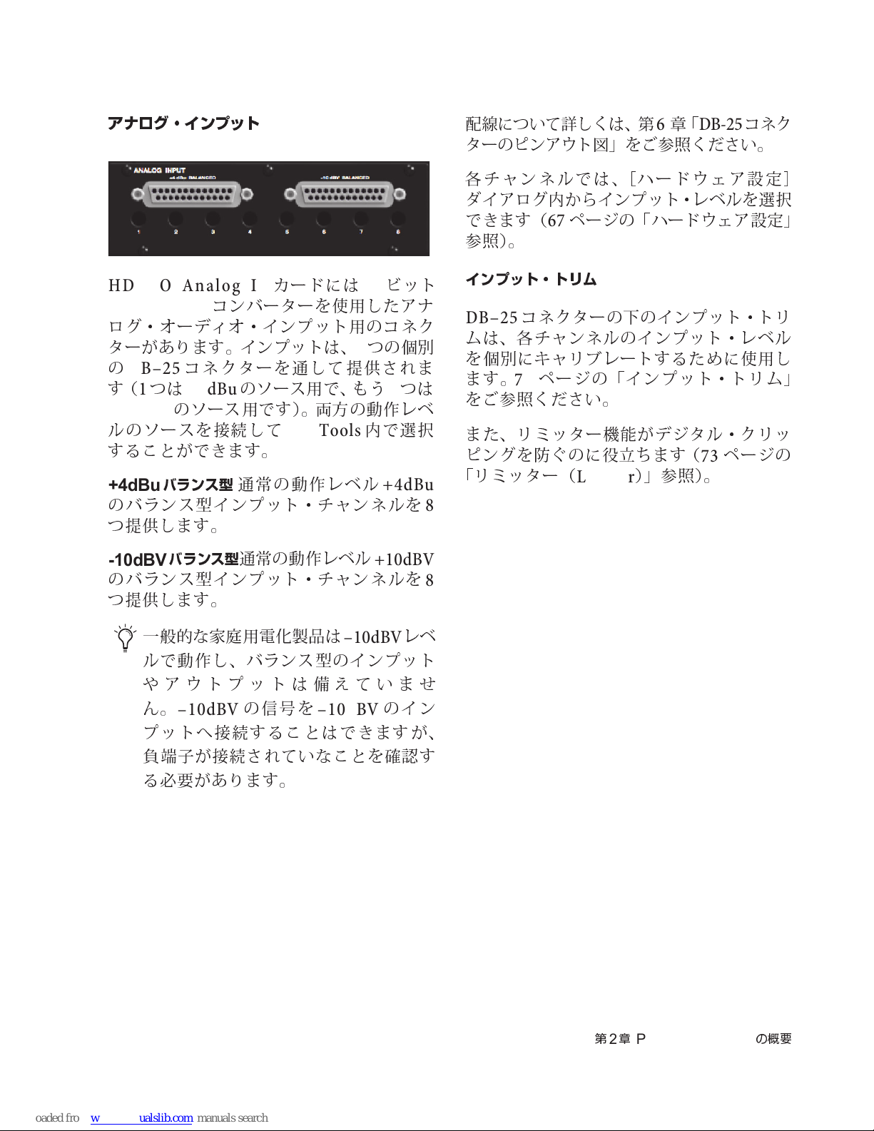
アナログ・インプット
配線
について詳しくは、
ターのピンアウト図」をご参照ください。
第6章
「
DB-25
コネク
HD I/O Analog In
/192kHz A/D
ログ・オーディオ・インプット用のコネク
ターがあります。インプットは、2つの個
の
DB–25
す(1つは
–10dBV
ルのソースを接続して
することができます。
+4dBu
のバランス型インプット・チャンネルを
つ提供します。
-10dBV
のバランス型インプット・チャンネルを
つ提供します。
バランス型
バランス型
コンバーターを使用したアナ
コネクターを通して提供されま
+4dBu
のソース用です)。両方の動作レベ
カードには24ビット
のソース用で、もう1つは
内
Pro Tools
通常の動作レベル
通常の動作レベル
で選択
+4dBu
+10dBV
別
各チャンネルでは、[ハードウェア設定
ダイアログ
できます(
参照)。
インプット・トリム
DB–25
ムは、各チャンネルのインプット・レベル
を個別にキャリブレートするために使用し
ます。
をご参照ください。
また、リミッター機能がデジタル・クリッ
ピングを防ぐのに
「リミッター(
内か
らインプット・レベルを選択
ページの「ハードウェア設定」
67
コネクターの下のインプット・トリ
ページの「インプット・トリム」
77
役立ち
Limiter
ます(
)」参照)。
8
8
ページの
73
]
一
般的な家庭
ルで動作 し、バラン ス型のインプット
やアウトプットは
ん
。
–10dBV
プットへ接続することはできますが、
負端子
る必要があります。
が接続されていなことを確認 す
用電化製品は
備え
の信号を
–10dBV
–10dBV
ていま
のイン
レベ
せ
第2章
Pro Tools | HD I/O
の概要
53
Page 58
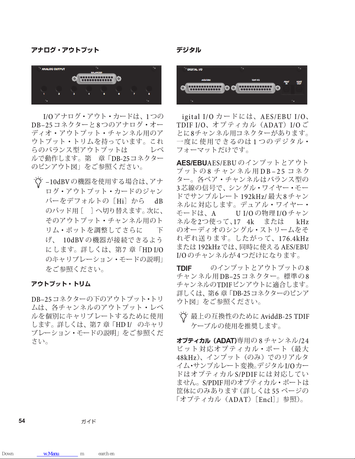
アナログ・アウトプット
デジタル
I/O
HD I/O
DB–25
ディオ・アウトプット・チャンネル用のア
ウトプット・トリムを持っています。これ
らのバランス型アウトプットは
ルで動作します。
のピンアウト図」をご参照ください。
アウトプット・トリム
DB–25
ムは、各チャンネルのアウトプット・レベ
ルを個別にキャリブレートするために使用
します。詳しくは、
ブレーション・モードの説明」をご参照くだ
さい。
アナログ・アウト・カードは、1つの
コネクターと8つのアナログ・オー
+4dBu
第6章
–10dBV
ログ・アウトプット・カードのジャン
パーをデフォルトの
のパッド用
そのアウトプット・チャンネル用のト
リム・ポットを
げ
、
に します。詳しくは、
のキャリブレーション・モードの説明」
をご参照ください。
コネクターの下のアウトプット・トリ
の機器を使用する場合は、アナ
[Lo]へ切り替え
–10dBV
の機器が接続できるよう
「
調整
第7章
DB-25
[Hi]か
してさらに
「
コネクター
ます。次に、
第7章
HD I/O
レベ
ら
–6dB
4dB
「
HD I/O
のキャリ
下
Digital I/O
TDIF I/O
とに8チャンネル用コネクターがあります。
一度に使用できるのは1つのデジタル・
フォーマットだけです。
AES/EBU
プットの8チャンネル用
ター。各ペア・チャンネルはバランス型の
芯線の信
3
ドでサンプルレート
ネルに対応します。デュアル・ワイヤー・
モードは、
ネルを2つ使って、
のオーディオのシングル・ストリームをそ
れぞれ送ります。したがって、
または
I/O
TDIF
チャンネル用
チャンネルの
詳しくは、
ウト図」をご参照ください。
オプティカル(
ビット対応オプティカル・ポート(最大
48kHz
イム・サンプルレート変換。デジタル
ドはオプティカル
ま
筐体
「オプティカル(
192kHz
のチャンネルが4つだけになります。
TDIF
最上の互換性のために
ケーブルの使用を
)、インプット(のみ)でのリアル タ
せん
。
にのみあります(詳しくは
カードには、
、オプティカル(
AES/EBU
号で、シングル・ワイヤー・モー
のインプットとアウト
192kHz/
AES/EBU I/O
176.4kHz
AES/EBU I/O
ADAT)I/O
I/O
192kHz
コネク
チャン
DB–25
最大8チャン
の
物理
または
176.4kHz
では、同時に使える
のインプットとアウトプットの
DB–25
TDIF
第6章
コネクター。標準の
ピンアウトに適合します。
「
DB-25
コネクターのピンア
AES/EBU
AviddB-25 TDIF
推奨
します。
)
専
ADAT
用の8チャンネル
I/O
には対応してい
ページの
55
)
[
Encl
]
」参照)。
S/PDIF
S/PDIF
用のオプティカル・ポートは
ADAT
/24
カー
、
ご
8
8
54
Pro Tools | HD I/O
ガイド
Page 59

デジタル
ルタイム・サンプルレート変換機能があ り
ます。た と
のオーディオを
リームできます。
詳しくは、
設定」をご参照ください。
カードのインプットには、リア
I/O
えば
、サンプルレート
96kHz
67
のセッションへスト
ページの「ハードウェア
44.1kHz
シャーシのコネクター
HD I/O
シに固定されている一式のコネクターがあ
ります。
これらのコネクターには、
ティカル
8
チャンネル)、および同
チャンネルが含まれています。画面上では、
これらのコネクターは、
Optical (ADAT
[
Encl
その他のコネクターは、
外部クロック・ポート、
HD Native
他
スへ接続するためのポートです。
のバックパネルの
I/O(ADAT
チャンネル、またはオプティカル
)
[
]
、
S/PDIF[Encl
、ま た は
の
Avid HD
オーディオ・インターフェー
AES/EBU[Encl
右半分
には、シャー
AES/EBU IO
フォーマットの別の
S/PDIFの2
軸
S/PDIF I/Oの2
AES/EBU[Encl
]
Encl
、
Optical(S/PDIF
]
と表示されます。
Loop Sync
HD I/OをHDX
ProTools|HD
]
、オ プ
ポート、
カードや
]
オプティカル(
これらのオプティカル・ポートは、オプテ ィ
カル(
トを最大8チャンネル、またはオプティカル
S/PDIF
チャンネル(ステレオ)送受信します。オプ
ティカル(
のサンプルレートに対応しています。
S/MUX
ポートはサンプルレート
オプティカル
プットを最大
ADAT
のインプットとアウトプットを
を使うと、これらのオプティカル・
176.4kHzと192kHz
のインプットとアウトプットを最大2チャン
ネル送受信します。
トは最大
ンネルのオプティカル・インプットおよび
アウトプットに対応しています。
同梱の
ドの
使用すれば、
176.4/192kHzで4
きます。
ライトパイプ準拠のデバイスについて
、
)
ライトパイプは、
準の8チャンネルのオプティカル・デジタル・
オーディオ接続用の規格です。光パイプは、
、
オプティカル・デッキ(
ラー・デジタル・マルチトラック(
コンバーターや
A/D
S/MUX
機器で使用されています。
、デジタル・コンソールな
ADAT)[Encl
)のインプットとアウトプッ
ADAT
)モー ド は、最 大
88.2kHzと96kHz
S/MUX
チャンネル、サンプルレート
4
のインプットとアウト
でオプティカル
TOS-Link
96 kHz
ADAT
のサ ン プ ル レートで2チャ
ADAT
ポートとデジタル
ポートを
88.2/96kHzで8
チャンネル使用で
Alesis
D/A
]
モードで、ポー
ADAT S/MUX
チャンネル、
が
開発
した業界標
ADAT
)、モジュ
コンバーター、
48kHz
S/MUX
I/O
MDM
ど多
2
で
カー
用に
)、
くの
これらはバランス
ターで、24ビット
オーディオ信号を送受信します。これらの
つのポートは、最大
2
レートに対応しています。
型3芯線
AES/EBU
192kHz
コネク
XLR
のステレオ・
のサンプル
第2章
Pro Tools | HD I/O
の概要
55
Page 60
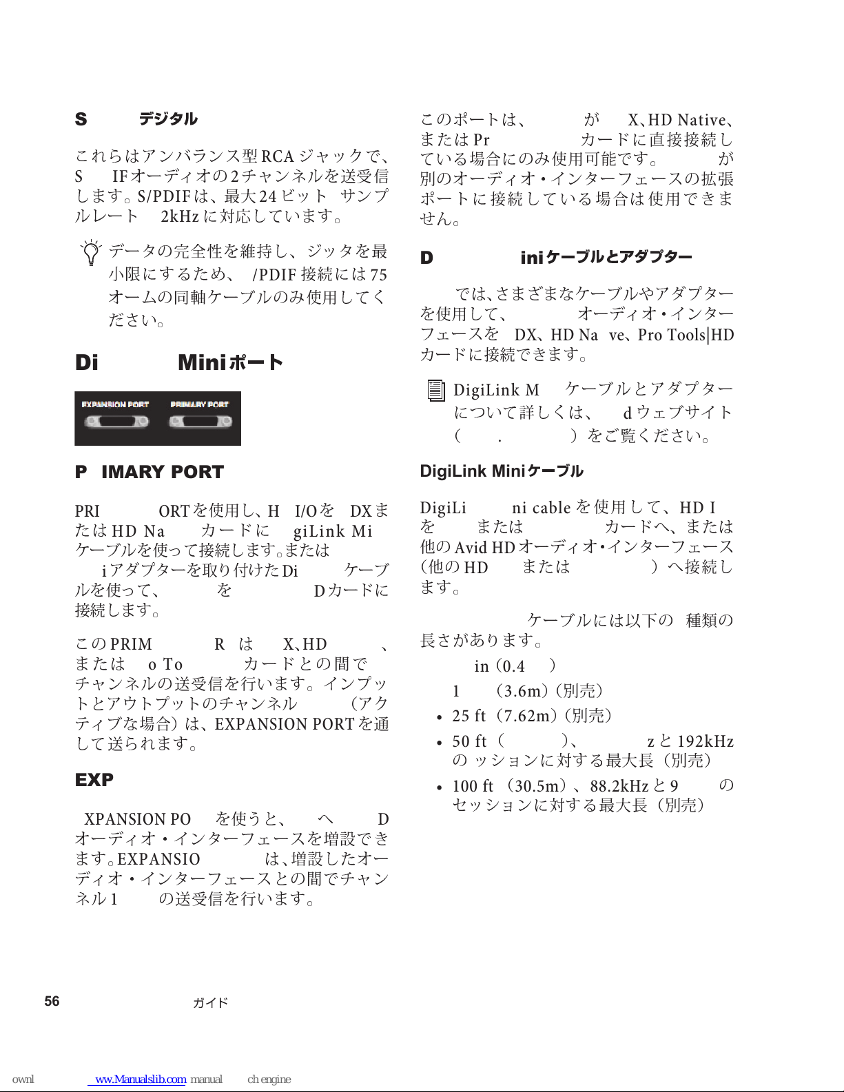
S/PDIF
これらはアンバランス
S/PDIF
します。
ルレート
デジタル
オーディオの2チャンネルを送受
S/PDIF
192kHz
I/O
は、最大24ビット/サンプ
に対応しています。
型
ジャックで、
RCA
信
このポートは、
または
ている場合にのみ使用可能です。
別
ポートに接続している場合は使用できま
せん
ProTools|HD
のオーディオ・インターフェースの拡張
。
HD I/OがHDX、HD Native
カードに直接接続し
HDI/O
が
、
データの完全性を
小
限にするため、
オームの同軸ケーブルのみ使用してく
ださい。
DigiLink Mini
維持
S/PDIF
ポート
し、ジッタを最
接続には
75
PRIMARY PORT
PRIMARY PORT
たは
HD Native
ケーブルを使って接続します。または
アダプターを取り付けた
Mini
ルを使って、
接続します。
この
PRIMARY PORTはHDX、HD Native
または
チャンネルの送受信を行います。インプッ
トとアウトプットのチャンネル
ティブな場合)は、
して送られます。
ProTools|HD
を使用し、
カードに
HD I/OをHDX
DigiLink Mini
DigiLink
HD I/OをPro Tools|HD
カードとの間で
17–32
EXPANSION PORT
DigiLink
カードに
ま
ケーブ
32
(アク
を通
EXPANSION PORT
EXPANSION PORT
オーディオ・インターフェースを増設でき
ます。
ディオ・インターフェースとの間でチャン
ネル
EXPANSION PORT
17–32
の送受信を行います。
を使うと、
は、増設したオー
I/OへHD|HD
DigiLink Mini
では、さまざまなケーブルやアダプター
Avid
を使用して、
フェースを
カードに接続できます。
HDX、HDNative、ProTools|HD
DigiLink Mini
について詳しくは、
(
www.avid.com
DigiLink Mini
DigiLink Mini cable
を
他
(他の
ます。
HDX
の
Avid HD
HDI/O
または
DigiLink Mini
⻑さがあります。
、
• 18 in(0.46m
• 12 ft (3.6m
• 25 ft (7.62m
•50 ft (15.25m)、176.4kHzと192kHz
の ッシ
ョンに対する最大⻑(別売)
• 100 ft (30.5m
セッショ
ケーブルとアダプタ ー
Avid HD
ケーブル
HD Native
オーディオ・インターフェース
または
ケーブルには以下の5種類の
ンに対する最大⻑(別売)
オーディオ・インター
ケーブルとアダプター
ウェブサイト
Avid
)をご覧ください。
を使用して、
カードへ、または
)へ接 続し
)
)(
)(
別売
別売
)、
HD OMNI
)
)
88.2kHzと96kHz
HD I/O
の
56
Pro Tools | HD I/O
ガイド
Page 61
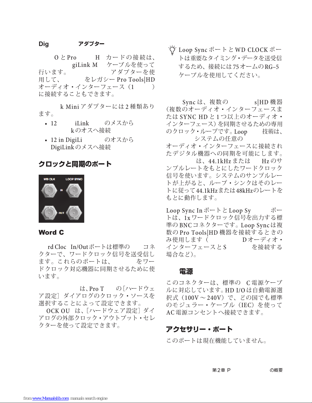
DigiLink Mini
HD I/OとProTools|HD
DigiLink/DigiLink Mini
行います。
用して、
オーディオ・インターフェース(
に接続することもできます。
HD I/O
DigiLink Mini
ます。
• 12 in DigiLink Mini
DigiLink
• 12 in DigiLink Mini
DigiLink
アダプター
カードの接続は、
ケーブルを使って
DigiLink Mini
をレガシー
アダプターには2種類あり
のオスへ接続
のメスへ接続
アダプターを使
ProTools|HD
のメスから
のオスから
クロックと同期のポート
192 I/O
Loop Sync
トは重要なタイミング・データを送受
するため、接続には75オームの
ケーブルを使用してください。
)
LOOP SYNC In/Out
Loop Sync
(複数のオーディオ・インターフェースま
たは
SYNC HDと1
インターフェース)を同期させるための専用
のクロック・ループです。
Pro Tools
オーディオ・インターフェースに接続され
たデジタル機器への同期を 可能にします。
Loop Sync
ンプルレートをもとにしたワードクロック
信
号を使います。システムのサンプルレー
トが上がると、ループ・シンクはそのレー
トに従って
もとに動作します。
ポートと
は、複 数 の
つ以上のオーディオ・
システムの
は、
44.1kHz
44.1kHz
または
WD CLOCK
Pro Tools|HD
Loop Sync
任意
の
Pro Tools|HD
または
48kHz
48kHz
のレートを
ポー
RG–59
機器
技術
のサ
信
は、
Word Clock In/Out
Word Clock In/Out
クターで、ワードクロック信号を送受信し
ます。これらのポートは、
ドクロック対応機器に同期させるために使
います。
WD CLOCK IN
ア設定]ダイアログのクロック・ソースを
選択することによって設定 できます。
CLOCK OUT
アログの外部クロック・アウトプット・セレ
クターを使って設定できます。
ポートは標準の
HD I/O
は、
Pro Tools
は、[ハードウェア設定]ダイ
の[ハードウェ
BNC
をワー
コネ
WD
Loop Sync In
トは、1xワードクロック信号を出力する標
準の
BNC
数の
Pro Tools|HD
み
使用します(
インターフェースと
場
合など)。
電源
AC
このコネクターは、標準の
ルに対応しています。
択式(
のモジュラー・ケーブル(
AC
100V〜240V
電源コンセントへ接続できます。
ポートと
コネクターです。
Loop Sync Out
機器を接続するときの
Pro Tools|HD
SYNC HD
HD I/O
)で、どの国でも標準
Loop Sync
オーディオ・
を接続する
電源ケーブ
AC
は自動電源選
)を使って
IEC
ポー
は複
アクセサリー・ポート
このポートは
現在
機能していま
せん
。
第2章
Pro Tools | HD I/O
の概要
57
Page 62

58
Pro Tools | HD I/O
ガイド
Page 63
第
3
章
Pro Tools | HD I/O
を接続する
Pro Tools | HD I/O
Pro Tools | HDNative、ProTools|HD
最大16チャンネルのアナログおよびデジタ
ル
HDX
I/O
HDX
パネルの拡張ポート、
の
カードを使用して
フェースを増設できます。
「
カードに接続する」をご参照ください。
HD Native
アでは、
を使って
I/O
2
Native
を使用して
スを増設できます。
「
Native
い。
を使用できます。
I/O
Pro Tools |
は
DigiLink Mini
カードへ接続します。
DigiLink Mini Port
Pro Tools | HD I/O を Pro Tools | HDX
カードのインストールについて、
HDX
詳しくは『
をご参照ください。
Pro Tools |
HD I/OはDigiLink Mini
HD Native
バックパネルの拡張ポート、HDカードの
つ目の
DigiLink Mini Port
カードの2つめの
HD
Pro Tools | HD I/O を Pro Tools | HD
カードに接続する」をご参照くださ
では、
Pro Tools |
ハードウェアでは、
HDX
ケーブルを使って
HD I/O
カードの2つ
HDX
、または追加の
オーディオ・インター
HD
60
インストール・ガイド
HD
HD Native
カードへ接続します。
ハードウェ
、ま た は
HDX
で使用する
バック
HDX
ページの
ケーブル
DigiLink Mini Port
オーディオ・インターフェー
63
ページの
HD
目
』
HD
HD
Pro Tools|HD
、
Pro Tools|HD
システムでは、
HDI/OはDigiLink Mini/DigiLink
を使って
HD OMNI
たは追加の
I/O|HD
ターフェースを増設することもでき ます。
65
Tools|HD
さい。
Pro Tools|HD
のバックパネルの拡張ポートま
ProTools|HD
システムへ
ページの「
カードに接続する」をご参照く だ
Pro Tools | HD I/Oを Pro
ProTools|HD
法について詳しくは、『
ユーザー・ガイド
オーディオ・インターフェースを
HD
カードへ接続します。
カードを使うと、
オーディオ・イン
HD
カードのインストール方
ProTools|HD
』をご参照ください。
ラックマウントする
HD I/OとAvid HD
フェースは、本体の
空間を必
内蔵
さい。本体をケースにラックマウントして
いる場合は、本体が
な部品を
テムを起動する前にケースの蓋や扉を取り
外してください。
要とします。本体の
のファンを取り外したりしないでくだ
損傷
する恐れがありますので、シス
オーディオ・インタ ー
両側
に通気(
急激
に加熱され、
冷却
両側を塞
ケーブル
)用の
いだり、
繊細
HD Native
て詳しくは、『
ガイド
カードのインストールについ
HD Native
』をご参照ください。
インストール・
第3章
Pro Tools | HD I/O
を接続する
59
Page 64
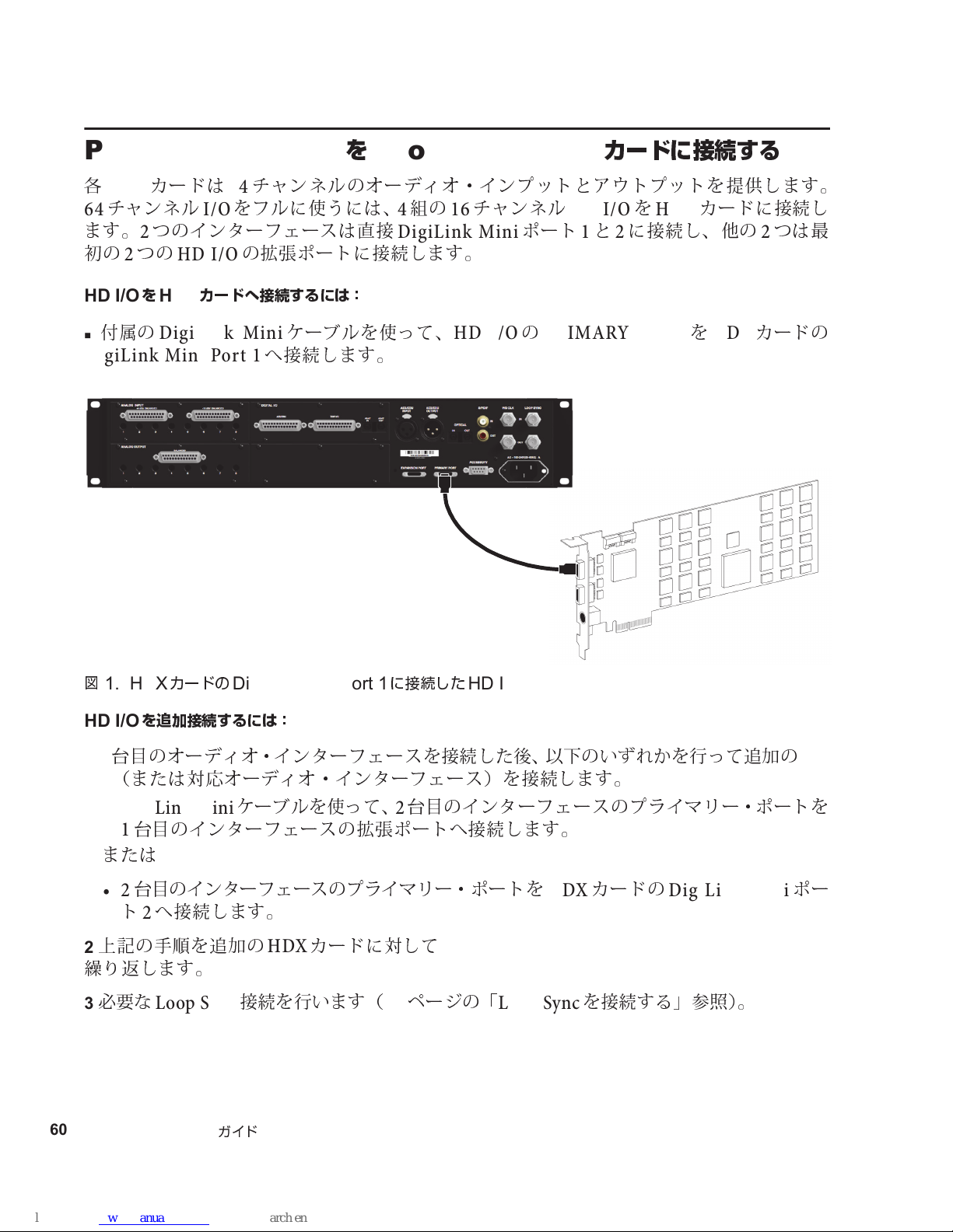
Pro Tools | HD I/O を Pro Tools | HDX
カードに接続する
各
64
ます。2つのインターフェースは直接
初
の2つの
HD I/OをHDX
付属の
DigiLink Mini Port 1
カードは64チャンネルのオーディオ・インプットとアウトプットを提供します。
HDX
チャンネル
HD I/O
DigiLink Mini
をフルに使うには、4組
I/O
の拡張ポートに接続します。
カードへ接続するには:
ケーブルを使って、
へ接続します。
の16チャンネル
DigiLink Mini
HD I/OのPRIMARY PORTをHDX
HD I/OをHDX
ポート1と2に接続し、他の2つは最
カードに接続し
カードの
図
1. HDX
HD I/O
台目
1
1
(または対応オーディオ・インターフェ ース)を接続します。
I/O
• DigiLink Mini
台目
1
または
台目
•2
ト2へ接続します。
上記の
2
繰り返
必
要な
3
60
Pro Tools | HD I/O
カードの
を追加接続するには:
のオーディオ・インターフェースを接続した後、以下のいずれかを行って追加の
のインターフェースの拡張ポートへ接 続します。
のインターフェースのプライマリー・ポートを
手順
します。
Loop Sync
DigiLink Mini Port 1
ケーブルを使って、2台目
を追加の
接続を行います(
ガイド
カードに対して
HDX
に接続した
ページの「
61
HD I/O
のインターフェースのプライマリー・ポートを
カードの
HDX
Loop Sync
を接続する」参照 )。
DigiLink Mini
HD
ポー
Page 65
Loop Sync
台
以上の
2
器を正しく同期させるため
オ・インターフェースを接続する例は
る例については、『
を接続する
オーディオ・インターフェースまたは
HD
Loop Sync
SYNC HD
ガイド』をご参照ください。
SYNC
を接続する必要があります。複数の
ページの
62
図 2をご参照ください。
同期機器を使用する場合は、機
Avid HD
SYNC
オーディ
を使用す
Loop Sync
BNC
1
を接続するには:
ケーブルを使って各のインターフェースの
Loop Sync In
ケーブルを使って最後のインターフェースの
BNC
2
スまたは
SYNCのLoop Sync In
へ接続します。
へ接続します。
Loop Sync Out
Loop Sync Outを1
を次のインタ−フェース の
台目のインタ−
フェー
第3章
Pro Tools | HD I/O
を接続する
61
Page 66
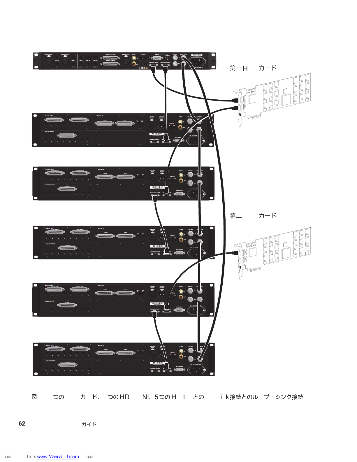
第一
HDX
カード
第二
HDX
カード
図
62
Pro Tools | HD I/O
2. 2
つの
カード、1つの
HDX
ガイド
HD OMNI、5
つの
HD I/O
との
DigiLink
接続とのループ・シンク接続
Page 67
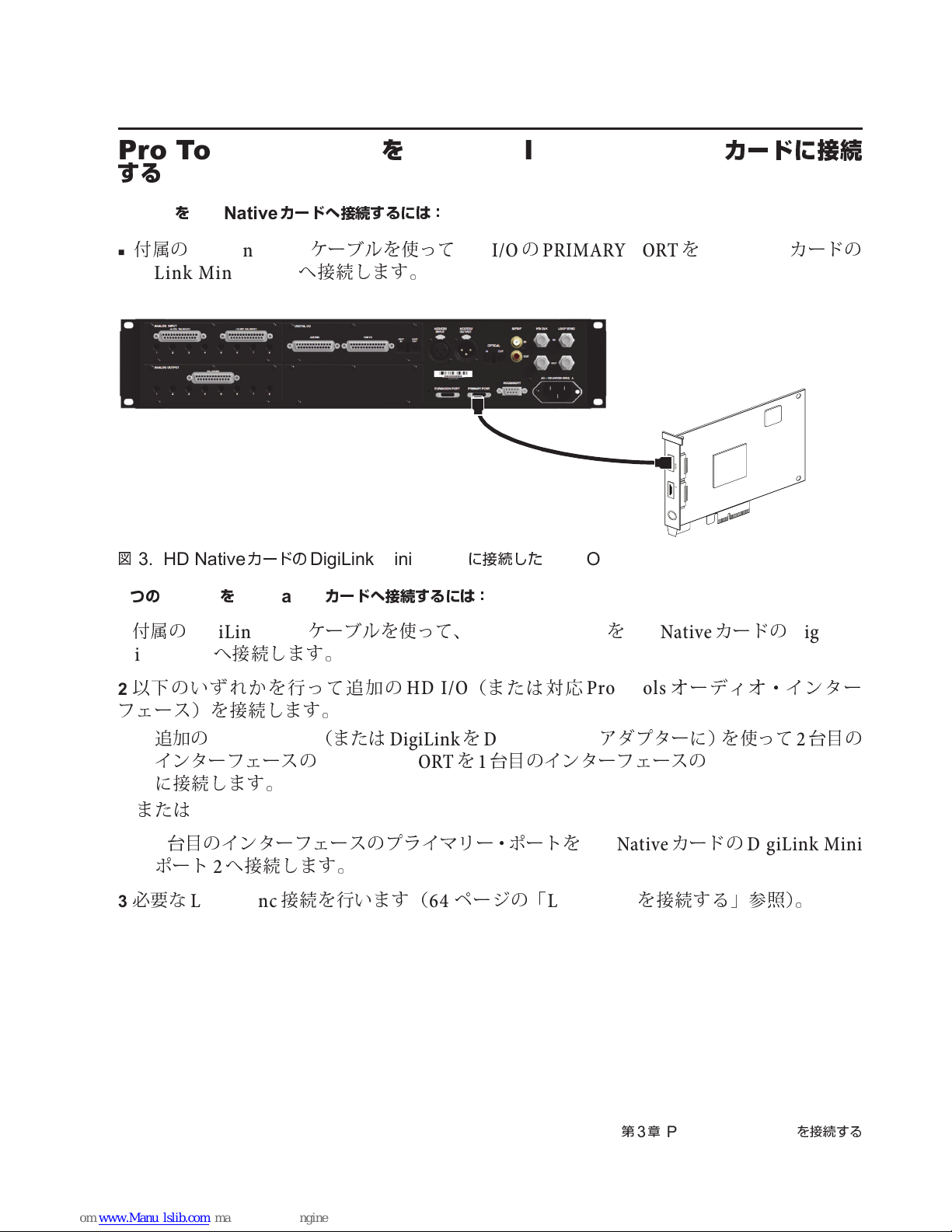
Pro Tools | HD I/O を Pro Tools | HD Native
する
カードに接続
HD I/OをHD Native
付属の
DigiLink Mini
カードへ接続するには:
DigiLink Mini Port 1
図
3. HD Native
つの
2
HD I/OをHD Native
付属の
1
DigiLink Mini
Mini Port 1
カードの
へ接続します。
ケーブルを使って
へ接続します。
DigiLink Mini Port 1
カードへ接続するには:
ケーブルを使って、
HD I/OのPRIMARY PORTをHD Native
PORT 1PORT 2
に接続した
PRIMARY PORTをHD Native
HD I/O
カードの
カードの
DigiLink
以下のいずれかを行って追加の
2
フェース)を接続します。
追加の
•
インターフェースの
に接続します。
または
•2
ポート2へ接続します。
必
要な
3
DigiLink Min
台目
のインターフェースのプライマリー・ポートを
Loop Sync
(または
PRIMARY PORTを1
接続を行います(
HD I/O
(または対応
DigiLinkをDigiLink Mini
台目
のインターフェースの
HD Native
ページの「
64
Loop Sync
Pro Tools
アダプターに)を使って2台目
オーディオ・インタ ー
EXPANSION PORT
カードの
を接続する」参照)。
第3章
Pro Tools | HD I/O
DigiLink Mini
を接続する
の
63
Page 68
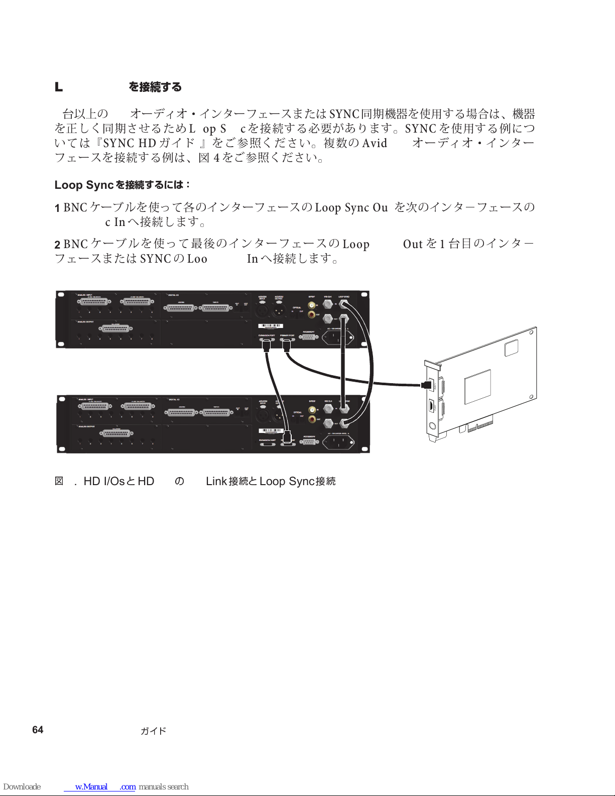
Loop Sync
PORT 1PORT 2
台
以上の
2
を正しく同期させるため
いては『
を接続する
オーディオ・インターフェースまたは
HD
Loop Sync
SYNC HD
ガイド 』をご参照ください。複数の
フェースを接続する例は、
を接続する必要があります。
図 4をご参照ください。
SYNC
同期機器を使用する場合は、機器
SYNC
Avid HD
を使用する例につ
オーディオ・インター
Loop Sync
BNC
1
Loop Sync In
BNC
2
を接続するには:
ケーブルを使って各のインターフェースの
へ接続します。
ケーブルを使って最後のインターフェースの
フェースまたは
SYNCのLoop Sync In
Loop Sync Out
へ接続します。
を次のインタ−フェースの
Loop Sync Outを1
台目のインタ−
図
4. HD I/OsとHD I/OのDigiLink
64
Pro Tools | HD I/O
ガイド
接続と
Loop Sync
接続
Page 69
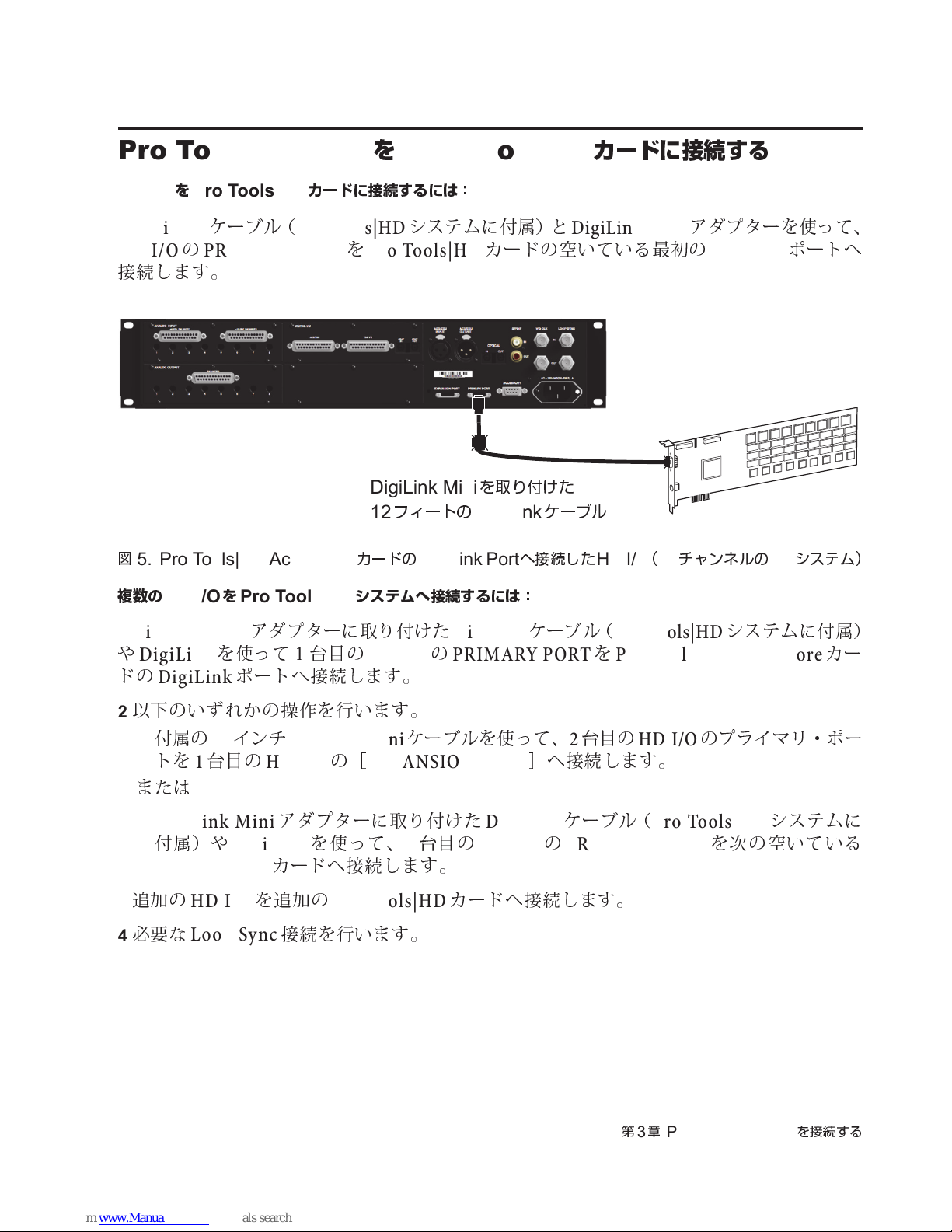
Pro Tools | HD I/Oを Pro Tools|HD
DigiLink Mini
を取り付けた
12
フィートの
DigiLink
ケーブル
カードに接続する
HD I/OをPro Tools|HD
DigiLink
ケーブル(
カードに接続するには:
Pro Tools|HD
システムに付属)と
HD I/OのPRIMARY PORTをPro Tools|HD
接続します。
図
5. Pro Tools|HD Accel Core
複数の
1
や
ドの
HD I/OをPro Tools|HD
DigiLink Mini
DigiLink
DigiLink
アダプターに取り付けた
を使って
ポートへ接続します。
1台目
カードの
システムへ接続するには:
DigiLink Port
DigiLink
の
HD I/OのPRIMARY PORTをProTools|HD Accel Core
DigiLink Mini
カードの空いている最初の
へ接続した
ケーブル(
HD I/O(16
Pro Tools|HD
アダプターを使って、
チャンネルの
DigiLink
システムに付属)
ポートへ
システム)
I/O
カー
以下のいずれかの操作を行います。
2
付属の18インチ
•
トを1台目
または
• DigiLink Mini
付属)や
Pro Tools|HD
追加の
3
必
4
要な
HD I/O
Loop Sync
の
DigiLink
DigiLink Mini
の
HD I/O
アダプターに取り付けた
カードへ接続します。
を追加の
接続を行います。
[
EXPANSION PORT
を使って、2台目
Pro Tools|HD
ケーブルを使って、2台目
]
へ接続します。
DigiLink
の
HD I/OのPRIMARY PORT
カードへ接続します。
ケーブル(
の
HD I/O
Pro Tools|HD
第3章
Pro Tools | HD I/O
のプライマリ・ポー
システムに
を次の空いている
を接続する
65
Page 70
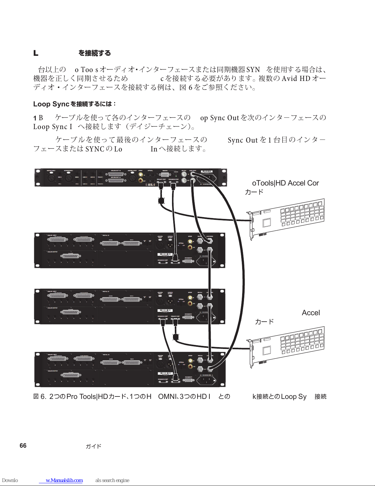
Loop Sync
ProTools|HD Accel Core
カード
Pro Tools|HD Accel
カード
台
以上の
2
機器を正しく同期させるため
を接続する
ProTools
オーディオ・インターフェースまたは同期機器
Loop Sync
を接続する必要があります。複数の
ディオ・インターフェースを接続する例は、
SYNC
図 6をご参照ください。
を使用する場合は、
Avid HD
オー
Loop Sync
BNC
1
Loop Sync In
BNC
2
を接続するには:
ケーブルを使って各のインターフェースの
へ接続します(デイジーチェーン)。
ケーブルを使って最後のインターフェースの
フェースまたは
SYNCのLoop Sync In
Loop Sync Out
へ接続します。
を次のインタ−フェースの
Loop Sync Outを1
台目のインタ−
図
66
Pro Tools | HD I/O
6. 2
つの
Pro Tools|HD
カード、1つの
ガイド
HD OMNI、3
つの
HD I/O
との
DigiLink
接続との
Loop Sync
接続
Page 71
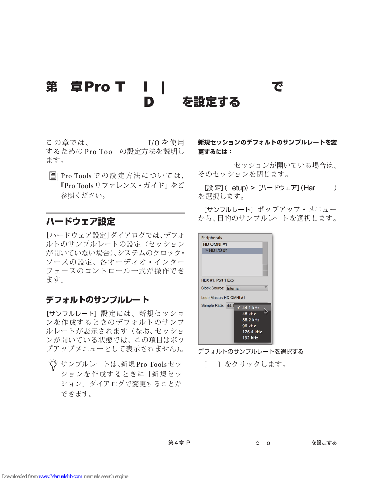
第
4
章
ProTools | HD Software
で
Pro Tools | HD I/O
この章では、
するための
ます。
Pro Tools
『
Pro Tools
参照ください。
Pro Tools | HD I/O
Pro Tools
での設定方法については、
リファレンス・ガイド
の設定方法を説明し
ハードウェア設定
[
ハードウェア設定]ダイアログでは、デフォ
ルトのサンプルレートの設定(セッション
が開いていない場合)、システムのクロック・
ソースの設定、各オーディオ・インター
フェースのコントロール一式が操作でき
ます。
を使用
』をご
を設定する
新規セッションのデフォルトのサンプルレートを変
更するには:
ProTools
1
そのセッションを閉じます。
[設 定]
2
を選択します。
[サンプルレート]
3
か
ら、
セッションが開いている場合は、
(
Setup)>
目的
のサンプルレートを選択します。
[ハードウェア]
ポップアップ・メニュー
(
Hardware
)
デフォルトのサンプルレート
[サンプルレート]
ンを作成するときのデフォルトのサンプ
ルレートが表示されます
ンが開いている
プアップメニューとして表示されま
サンプルレートは、新規
ションを作成するときに[新規セッ
ション]ダイアログで変更することが
できます。
設定には、新規セッショ
状態
では、この
(なお、セッショ
項目
はポッ
せん
)。
ProTools
セッ
第4章
デフォルトのサンプルレートを選択する
[OK]
4
Pro Tools | HD Software でPro Tools | HD I/O
をクリックします。
を設定する
67
Page 72
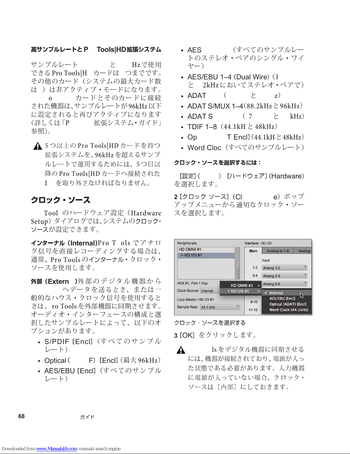
高サンプルレートと
サンプルレート
できる
その他のカード(システムの最大カード数
は7)は非アクティブ・モードになります。
Pro Tools|HD
Pro Tools|HD
された機器は、サンプルレートが
に設定されると再びアクティブになります
(詳しくは「
参照)。
5
拡張システムを、
ルレートで運用するためには、
降の
I/O
Pro Tools
つ以上の
Pro Tools|HD
を取り外さなければなりません。
Pro Tools|HD
176.4kHzと192kHz
カードは4つまでです。
カードとそのカードに接続
拡張システム・ガイド」
Pro Tools|HD
96kHz
カードへ接続された
拡張システム
で使用
つ目以
5
以下
96kHz
カードを持つ
を超えるサンプ
•
AES/EBU 1–8
トのステレオ・ペアのシングル・ワイ
ヤ
ー)
•
AES/EBU 1–4(Dual Wire
と
192kHz
•
ADAT 1–8
•
ADAT S/MUX 1–4
•
ADAT S/MUX1–2
•
TDIF 1–8
•
Optical ADAT Encl
•
Word Clock
クロック・ソースを選択するには:
[設定](
1
を選択します。
Setup)>
(すべてのサンプルレー
)
(
においてステレオ・ペアで)
(
44.1kHと48kHz
(
88.2kHzと96kHz
(
176.4kHzと192kHz
(
44.1kHと48kHz
]
(
44.1kHと48kHz
(すべてのサンプルレート)
[ハードウェア](
Hardware
176.4kHz
)
)
)
)
)
)
クロック・ソース
ProTools
Setup
ソース
インターナル(
グ信号を直接レコーディングする場合は、
通常、
ソースを使用します。
外部(
Pro Tools
般的
なハウス・クロック信号を使用すると
きは、
オーディオ・インターフェースの構成と選
択したサンプルレートによって、以下のオ
プションがあります。
•
S/PDIF[Encl
レート)
•
Optical(S/PDIF) [Encl
•
AES/EBU[Encl
レート)
のハードウェア設定(
)ダイアログでは、システムの
が設定できます。
)
Internal
ProTools
)
External
Pro Tools
外部のデジタル機器から
へデータを送るとき、または一
を外部機器に同期させます。
ProTools
の
インターナル
]
(すべてのサンプル
]
(すべてのサンプル
・クロック・
]
(最大
Hardware
クロック・
でアナロ
96kHz
)
[クロック ソース](
2
アップメニューから
スを選択します。
クロック・ソースを選択する
[OK]
3
をクリックします。
ProTools
には、機器が接 続さ れて おり 、電源が入っ
た状態である必要があり ます。入力機器
に電源が入っていない場合、クロック・
ソースは[内部]にしておきます。
をデジタル機器に同期させる
Clock Source
適切
なクロック・ソー
)
ポップ
68
Pro Tools | HD I/O
ガイド
Page 73
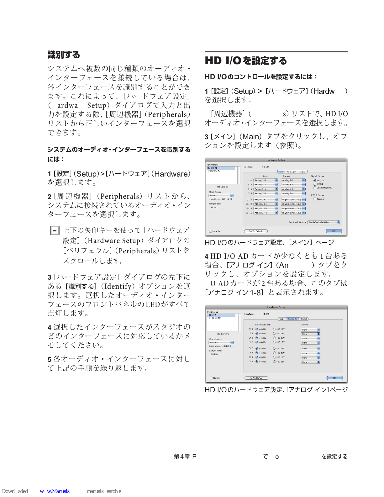
識別する
システムへ複数の同じ種類のオーディオ・
インターフェースを接続して いる場合は、
各インターフェースを識別することができ
ます。これによって、[ハードウェア設定
(
Hardware Setup
力を設定する際、[周辺機器](
リストから正しいインターフェースを選択
できます。
システムのオーディオ・インターフェースを識別する
には:
)ダイアログで入力と
Peripherals
出
HD I/O
HD I/O
[設定]
1
]
を選択します。
[
周辺機器](
2
)
を設定する
のコントロールを設定するには:
(
Setup)>
[ハードウェア]
Peripherals
)リストで、
(
オーディオ・インターフェースを選択します。
[メイン](
3
Main
)
タブをクリックし、オプ
ションを設定します(参照)。
Hardware
HD I/O
)
[設定](
1
Setup)>
[ハードウェア](
Hardware
を選択します。
[
周辺機器](
2
Peripherals
)リス トから、
システムに接続されているオーディオ・イン
ターフェースを選択します。
上下の矢印キーを使って[ハードウェア
設定](
[ペリフェラル](
スクロールします。
[
ハードウェア設定]ダイアログの左下に
3
ある
[識別する]
Hardware Setup
Peripherals
(
Identify
)ダイアログの
)リストを
)オプ ションを選
択します。選択したオーディオ・インター
フェースのフロントパネルの
点灯
します。
選択したインターフェースがスタジオの
4
ど
のインターフェースに対応しているかメ
LED
がすべて
モしてください。
)
HD I/O
4
場
のハードウェア設定、[メイン]ページ
HD I/O AD
合、
[アナログ イン](
カードが少なくとも1台
Analog In
リックし、オプションを設定し ます。
I/O AD
[アナログ イン
カードが2台
1-8
ある場合、このタブは
]
と表示されます。
)
タブをク
ある
HD
各オーディオ・インターフェースに対し
5
て上記の
手順を繰り返
します。
HD I/O
第4章
Pro Tools | HD Software でPro Tools | HD I/O
のハードウェア設定、[アナログ イン]ページ
を設定する
69
Page 74
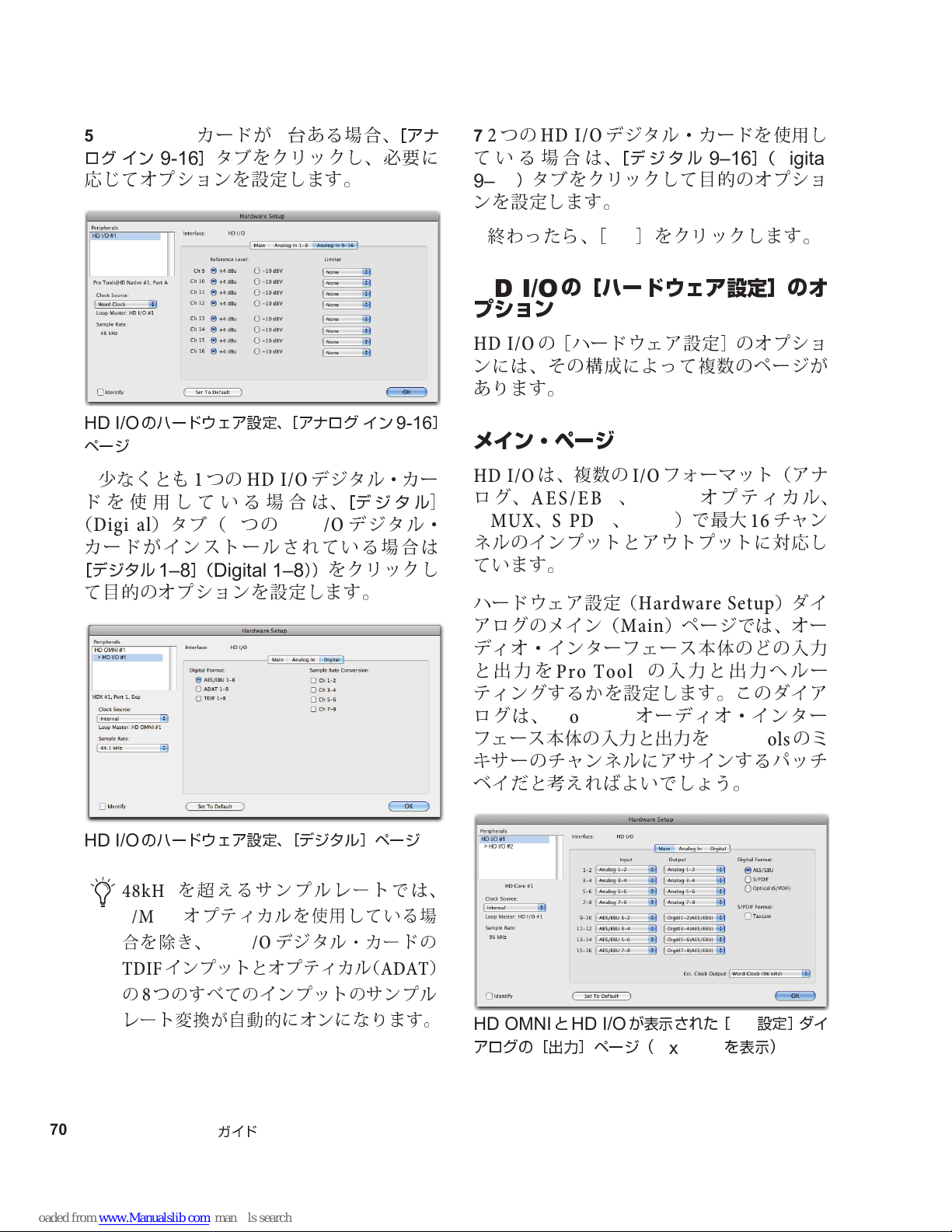
HD I/O AD
5
イン
ログ
応じてオプションを設定します。
カードが2台
]
9-16
タブをクリックし、必要に
ある場合、
[アナ
つの
2
7
ている場合は、
9–16
ンを設定します。
終わ
8
HD I/O
)
タブをクリックして
ったら、
デジタル・カードを使用 し
[デジタル
[OK]
9–16](Digital
目的
のオプショ
をクリックします。
HD I/O
ページ
6
ドを使用している場合は、
(
Digital
カードがインストールされている場合は
[デジタル
て
のハードウェア設定、[アナログ イン
少
なくとも1つの
)タ ブ(2つの
HD I/O
HD I/O
1–8](Digital 1–8
目的
のオプションを設定します。
9-16
デジタル・カ ー
[デジタル
デジタル・
))
をクリックし
HD I/O
の[ハードウェア設定]のオ
プション
HD I/O
ンには、その構成によって複数のページが
あります。
]
の[ハードウェア設定]のオプショ
メイン・ページ
は、複数の
AES/EBU、ADAT
]
HD I/O
ログ、
S/MUX、S/PDIF、TDIF
ネルのインプットとアウトプットに対応し
ています。
ハードウェア設定(
アログのメイン(
ディオ・インターフェース本体のどの入力
と出力を
ティングするかを設定します。このダイア
ログは、
フェース本体の入力と出力を
キ
サーのチャンネルにアサインするパッチ
ベイだと
ProTools
ProTools
考えれば
フォーマット(アナ
I/O
オプティカル、
)で最大16チャン
Hardware Setup
)ページでは、オー
Main
の入力と出力へルー
オーディオ・インター
ProTools
よいでしょう。
)ダイ
のミ
HD I/O
70
Pro Tools | HD I/O
のハードウェア設定、[デジタル]ページ
48kHz
S/MUX
合を除き、
TDIF
の
レート変換が自動的にオンになります。
を超えるサンプルレートでは、
オプティカルを使用している場
HD I/O
インプットとオプティ カル(
つのすべてのインプットのサンプル
8
ガイド
デジタル・カードの
ADAT
)
HD OMNIとHD I/O
アログの[出力]ページ(
が表⺬された[
8 x 8 x 8
設定]ダイ
I/O
を表⺬)
Page 75
入力(
Input
)
同じフォーマットのインプットとアウトプット
インプットのポップアップメ ニューから、
Pro Tools
テレオ・ペ ア(
応する
どの物理
ストールされている
サンプルレートによって異なります(たと
えば
、
れていなければアナログ・インプットは使
用できま
これらの設定は、セッションにではなく、
システムに保存されます。
出力(
アウトプットのポップアップメニューから、
Pro Tools
各ステレオ・ペア(
に対応する
します。どの
るかは、インストールされている
張カードとサンプルレートによって異なり
ます(たと
ストールされていなければアナログ・アウト
プットは使用できま
セッションにではなく、システムに保存さ
れます。
複数のインプットやアウトプットを 選
択するときは、
または
ください。すべてのインプットまたはア
ウトプットの設定をカスケードする と
きは、
または
してください。
のインプット・チャンネルの各 ス
1–2、3–4、...15–16
物理
インプット・ペアを選択します。
インプットが使用できるかは、イン
HD I/O
HD I/O AD
せん
Output
のアウトプット・チャンネルの
カードがインストールさ
)。
)
拡張カードと
1–2、3–4、...15–16
物理
アウトプット・ペアを選択
物理
アウトプットが使用でき
HD I/O
えば
、
HD I/O DA
せん
Control-
Start-
クリック(
Command-Option-
Control-Alt-
クリック(
カードがイン
)。これらの設定は、
クリック(
Windows
クリック(
Windows
)に対
拡
Mac
)して
Mac
)
)
)
)
同じようなフォーマットの入出力は、入力
と出力のチャンネル・ポップアップメ
ニューの中で
HDI/O
ウトプットは
され、
のインプットとアウトプットは
1–2
[
AES/EBU 7-8
つの デジタル・カードを持つ
2
追加の
9–10
13–14
デジタル・フォーマット
内蔵
のデジタル・インプット・フォーマットを
選択してください(追加の
カードのオプションは、それぞれのカードに
対応する
定してください)。
内蔵
HD I/O
]、[
AES/EBU 3–4
AES/EBU I/O
]、[
]、[
デジタル
AES/EBU.
インプット。
S/PDIF
プット。
Optical
(同軸)インプット、最大
ションは、
は選択できま
S/PDIF
2
(S/PDIF)
フォーマット
Tascam DA-30 DAT
ある
S/PDIF(Sony/Phillips Digital
Interface Format
マット]の下の
択してください。
区別
されています。たと
の
AES/EBU
[
AES/EBU[Encl
デジタル・カードの
]
のインプットとア
]、[
AES/EBU 5–6
とペアで表示されます。
ポート
AES/EBU 11–12
AES/EBU 15–16
を使用するときは、以下
I/O
[デジタル]
最大2チャンネルの
チャンネルの
チャンネルの
2
]
タブをクリックして設
S/PDIF
96kHz
96kHz
より高いサンプルレートで
せん
。
レコーダーと互換性の
)では、
[
Tascam
[
]
えば
]]
と表示
AES/EBU
[
AES/EBU
HD I/O
は[
]、[
と表示されます。
では、
AES/EBU
AES/EBU
HD I/O Digital
AES/EBU
(同軸)イン
S/PDIF
。このオプ
S/PDIF
オプションを選
フォー
、
]、
第4章
Pro Tools | HD Software でPro Tools | HD I/O
を設定する
71
Page 76
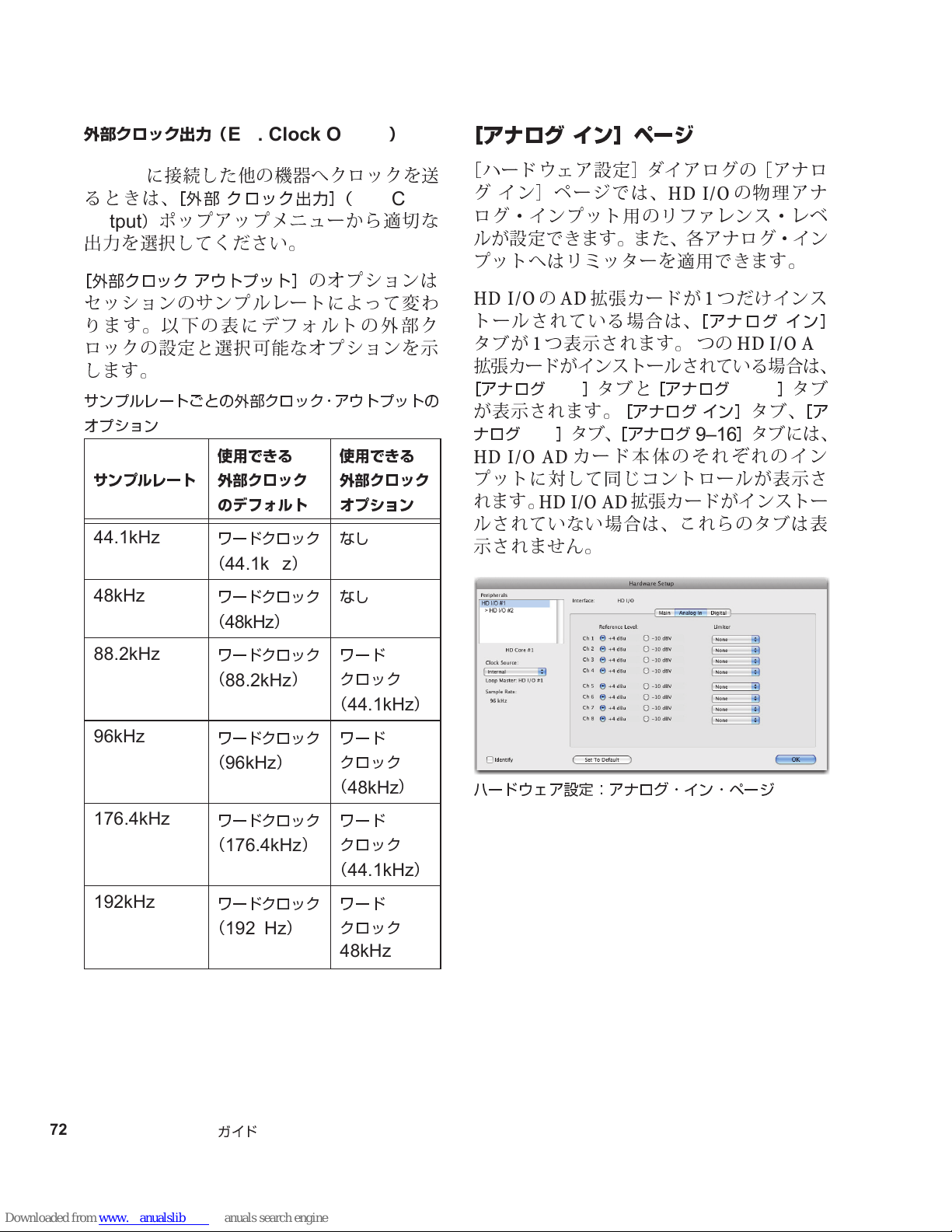
外部クロック出力(
HD I/O
るときは、
Output
出
[外部クロック アウトプット]
に接続した他の機器へクロックを
[外 部 クロック出力](
)
ポップアップメニューから
力を選択してください。
Ext. Clock Output
のオプションは
)
Ext. Clock
適切
セッションのサンプルレートによって変
ります。以下の表にデフォルトの外部ク
ロックの設定と選択可能なオプションを示
します。
サンプルレートごとの外部クロック・アウトプットの
オプション
サンプルレート
44.1kHz
使用できる
外部クロック
のデフォルト
ワードクロック
(
44.1kHz
)
使用できる
外部クロック
オプション
なし
[アナログ イン]ページ
[
送
な
わ
ハードウェア設定]ダイアログの[アナロ
グ イン]ページでは、
ログ・インプット用のリファレンス・レベ
ルが設定できます。また、各アナログ・イン
プットへはリミッターを適用できます。
HD I/OのAD
拡張カードが1つだけインス
トールされている場合は、
タブが1つ表示されます。2つの
拡張カードがインストールされている場合は、
[アナログ
1–8
]
タブと
が表示されます。
]
ナログ
1–8
HD I/O AD
タブ、
カード本体のそれぞれのイン
プットに対して同じコントロールが表示さ
れます。
HD I/O AD
ルされていない場合は、これらのタブは表
示されま
せん
。
の
HD I/O
[アナログ イン]
物理
HD I/O AD
[アナログ
[アナログ イン]
[アナログ
9–16
9–16
拡張カードがインストー
]
タブ、
]
タブには、
アナ
タブ
[ア
48kHz
88.2kHz
96kHz
176.4kHz
192kHz
ワードクロック
(
48kHz
ワードクロック
(
88.2kHz
ワードクロック
(
96kHz
ワードクロック
(
176.4kHz
ワードクロック
(
192kHz
)
)
)
)
)
なし
ワード
クロック
(
44.1kHz
ワード
クロック
(
48kHz
ワード
クロック
(
44.1kHz
ワード
クロック
48kHz
)
)
ハードウェア設定:アナログ・イン・ページ
)
72
Pro Tools | HD I/O
ガイド
Page 77
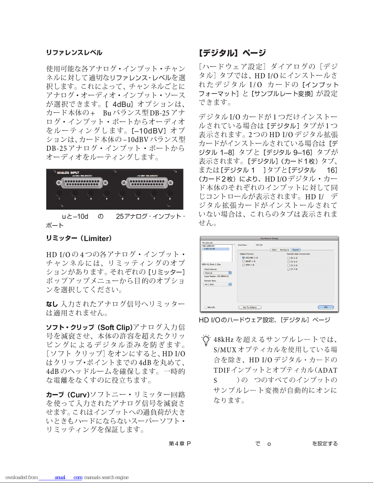
リファレンスレベル
使用可能な各アナログ・インプット・チャン
ネルに対して
適切
な
リファレンス・レベル
を選
択します。これによって、チャンネルごとに
アナログ・オーディオ・インプット・ソース
が選択できます。
カード本体の
[
+4dBu
+4dBu
バランス
]
オプションは、
型
DB-25
アナ
ログ・インプ ット・ポー トからオーディオ
をルーティングします。
ションは、カード本体の
DB-25
アナログ・インプット・ポートから
[
–10dBV
–10dBV
]
オプ
バランス
型
オーディオをルーティングします。
+4dBuと–10dBVのDB-25
ポート
アナログ・ インプ ット ・
[デジタル]ページ
[
ハードウェア設定]ダイアログの[デジ
タル]タブでは、
れたデジタル
フォーマット]
HD I/O
I/O
と
[サンプルレート変換]
できます。
デジタル
カードが1つだけインストー
I/O
ルされている場合は
表示されます。2つの
カードがインストールされている場合は
ジタル
1–8
表示されます。
または
[デジタル
(カード
枚)により、
2
タブと
[デジタル
[デジタル](カード1枚)
1–8
]
ド本体のそれぞれの イン プ ッ ト に 対して同
じコントロールが表示されます。
ジタル拡張カードがインストールされて
いない場合は、これらのタブは表示されま
せん
。
にインストールさ
カードの
[デジタル]
HD I/O
[インプット
デジタル拡張
9–16
]
タブと
[デジタル
HD I/O
デジタル・カー
が設定
タブが1つ
[デ
]
タブが
タブ、
9–16
HD I/O
]
デ
リミッター(
HD I/Oの4
Limiter
つの各アナログ・インプット・
)
チャンネルには、リミッテ ィングのオプ
ションがあります。それぞれの
ポップアップメニューから
[リミッター]
目的
のオプショ
ンを選択してください。
なし
入力されたアナログ信号へリミッター
は適用されま
ソフト・クリップ(
号を
減衰させ
ピングによるデジタル
[
ソフト クリップ]をオンにすると、
はクリップ・ポイントまでの
のヘッドルームを確保します。一時
4dB
な電離をなくすのに
カーブ(
Curv
を使って入力されたアナログ信号を
せ
ます。これはインプットへの
せん
。
)
Soft Clip
、本体の
アナログ入力
許容を超え
歪み
を防ぎます。
たクリッ
HD I/O
を丸めて、
4dB
役立ち
)
ソフトニー・リミッター回路
ます。
過負荷
減衰
が大き
いときもハードにならないスーパーソフト・
リミッティングを保証します。
信
的
さ
HD I/O
のハードウェア設定、[デジタル]ページ
48kHz
S/MUX
合を除き、
TDIF
S/MUX
サンプルレート変換が自動的にオンに
なります。
を超えるサンプルレートでは、
オプティカルを使用している場
HD I/O
インプットとオプティカル(
)の8つのすべてのインプットの
デジタル・カードの
ADAT
第4章
Pro Tools | HD Software でPro Tools | HD I/O
を設定する
73
Page 78
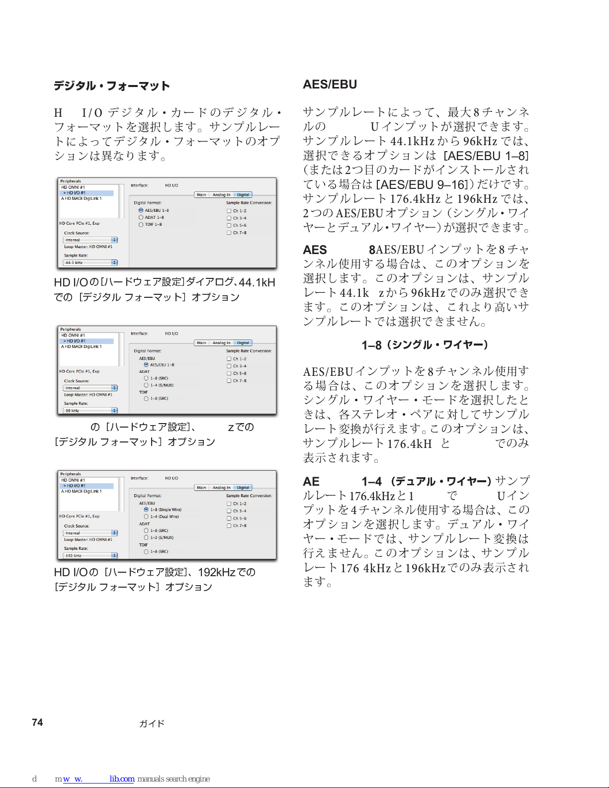
デジタル・フォーマット
AES/EBU
HD I/O
フォーマットを選択します。サンプルレー
トによってデジタル・フォーマットのオプ
ションは異なります。
HD I/O
での[デジタル フォーマット]オプション
HD I/O
[デジタル
デジ タ ル・カー ド の デジタル・
の[ハードウェア設定]ダイアログ、
の[ハードウェア設定]、
フォーマット]オプション
96kHz
44.1kHz
での
サンプルレートによって、最大8チャンネ
ルの
AES/EBU
サンプルレート
選択できるオプションは
(または2つ目のカードがインストールされ
ている場合は
サンプルレート
つの
2
ヤ
AES/EBU
ーとデュアル・ワイヤー)が選択できます。
AES/EBU 1-8
ンネル使用する場合は、このオプションを
選択します。このオプションは、サンプル
レート
ます。このオプションは、これより高いサ
ンプルレートでは選択できま
44.1kHz
AES/EBU 1–8
AES/EBU
る場合は、このオプションを選択します。
シングル・ワイヤー・モードを選択したと
きは、各ステレオ・ペアに対してサンプル
レート変換が行えます。このオプションは、
サンプルレート
表示されます。
インプットが選択できます。
か
44.1kHz
[
AES/EBU 9–16
ら
96kHz
[
AES/EBU 1–8
]
)だけです。
176.4kHzと196kHz
オプション(シングル・ワイ
AES/EBU
か
(シングル・ワイヤー)
インプットを8チャンネル使用す
インプットを8チャ
ら
96kHz
でのみ選択でき
せん
176.4kHzと196kHz
。
では、
では、
での
み
]
HD I/O
[デジタル
74
Pro Tools | HD I/O
の[ハードウェア設定]、
フォーマット]オプション
ガイド
192kHz
での
AES/EBU 1–4
ルレート
プットを4チャンネル使用する場合は、こ の
オプションを選択します。デュアル・ワイ
ヤ
ー・モードでは、サンプルレート変換は
行えま
レート
ます。
176.4kHzと196kHzでAES/EBU
せん
176.4kHzと196kHz
(デュアル・ワイヤー)
。このオプションは、サンプル
でのみ表示され
サンプ
イン
Page 79
ADAT
サンプルレートによって、最大8チャンネルの
ADAT
ルレート
るオプションは
のカード がインストールされている場合は
[
ADAT 9–16
88.2kHz
が選択できます(
ADAT 1-8
ル使用する場合は、このオプションを選択
します。このオプションは、サンプルレート
44.1kHzと48kHz
オプションは、これより高いサンプルレー
トでは選択できま
1–8(SRC
を用いた
使用する場合は、このオプションを選択し
ます。このオプションは、サンプルレート
88.2kHz
プションは、
トでは選択できま
インプットが選択できま す。サンプ
44.1kHzと48kHz
[
ADAT 1–8
]
)だけです。サンプルレート
以上では、2つの
SRCとS/MUX
ADAT
)
自動サンプルレート変換(
ADAT
以上でのみ表示されます。このオ
インプットを8チャンネ
でのみ選択できます。この
せん
インプットを8チャンネル
96kHz
より高いサンプルレー
せん
では、選択でき
]
(または2つ
ADAT
。
。
オプション
)。
SRC
目
1–4(S/MUX)
を用いた
使用する場合は、このオプションを選択し
ます。このオプションは、サンプルレート
88.2kHzと96kHz
1–2(S/MUX)
を用いた
使用する場合は、このオプションを選択し
ます。このオプションは、サンプルレート
176.4kHzと196kHz
S/MUX(Sample Multiplexing
ADAT
インプットを4チャンネル
でのみ表示されます。
S/MUX(Sample Multiplexing
ADAT
インプットを2チャンネル
でのみ表示されます。
TDIF
サンプルレートによって、8チャンネルの
TDIF(Tascam Digital Input Format
プット(2つ目のカードがインストールさ
れている場合は、
)
]
9–16
ト変換(
ます。
TDIF 1-8
使用する場合は、このオプションを選択し
ます。このオプションは、サンプルレート
)が選択できます。自動 サンプルレー
SRC
TDIF
44.1kHzと48kHz
[
TDIF 1–8
)を行う
インプットを8チャンネル
かどうか
でのみ選択できます。
]
または
)イン
[
TDIF
は選択でき
)
)
)
1–8(SRC
た
TDIF
合は、このオプションを選択します。このオ
プションは、サンプルレート
でのみ選択できます。
第4章
Pro Tools | HD Software でPro Tools | HD I/O
自動サンプルレート変換を用い
インプットを8チャンネル使用する
場
88.2kHzと48kHz
を設定する
75
Page 80
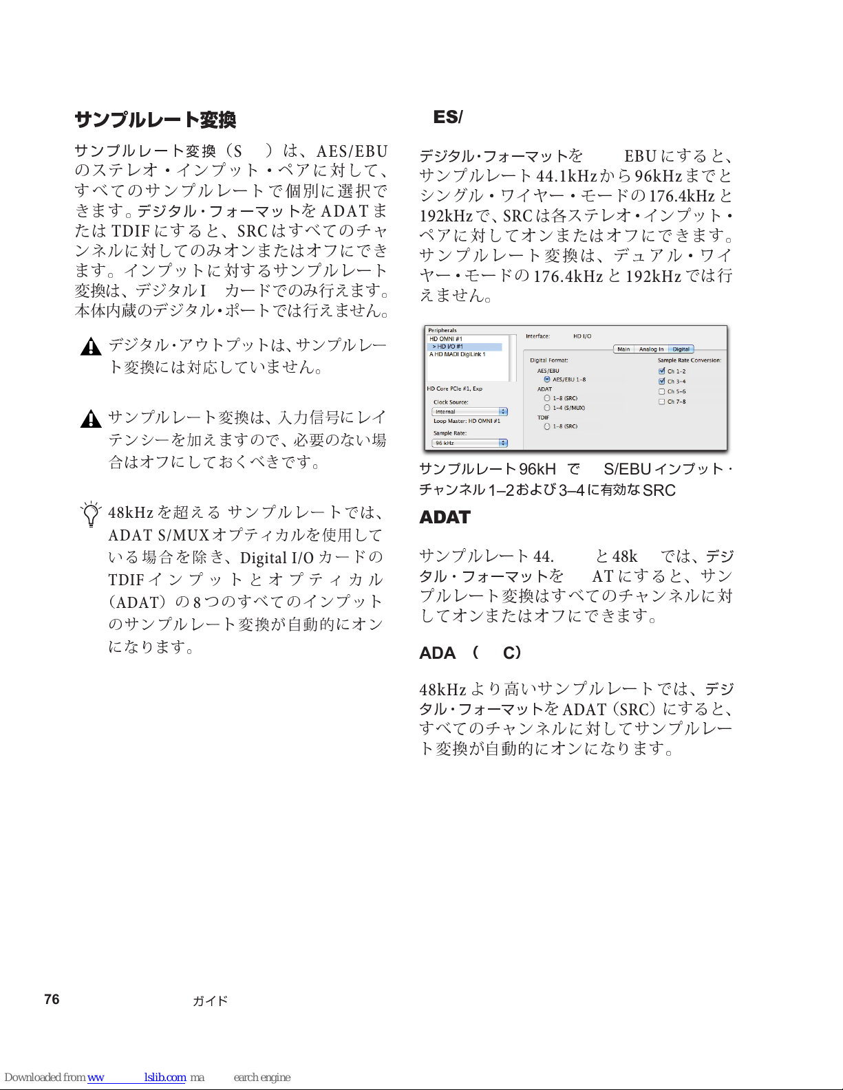
サンプルレート変換
AES/EBU
サンプルレート変換
のステレオ・インプット・ペアに対して、
すべてのサン プルレートで個別に選択で
きます。
たは
ンネルに対してのみオンまたはオフにでき
ます。インプットに対するサンプルレート
変換は、デジタル
本
体内蔵
デジタル・フォーマット
TDIF
デジタル・アウトプットは、サンプルレー
ト変換には対応して
サンプルレート変換は、入力信号にレイ
テンシーを加えますので、必要のない場
合はオフにしておくべきです。
48kHz
にすると、
のデジタル・ポートでは行えま
を超える サンプルレートでは、
ADAT S/MUX
いる場合を除き、
インプットとオプティカル
TDIF
(
ADAT
のサンプルレート変換が 自動的にオン
になります。
)の8つのすべてのインプット
(
カードでのみ行えます。
I/O
オプティカルを使用して
)は、
SRC
を
はすべてのチャ
SRC
いま
せん
Digital I/O
AES/EBU
ADAT
。
カードの
せん
ま
。
デジタル・フォーマット
サンプルレート
シングル・ワイヤー・モードの
192kHz
ペアに対してオンまたはオフにできます。
サンプルレート変換は、デュアル・ワイ
ヤ
えません
サンプルレート
チャンネル
で、
SRC
ー・モードの
。
および
1–2
96kHzでAES/EBU
を
AES/EBU
か
44.1kHz
は各ステレオ・インプット・
ら
176.4kHzと192kHz
に有効な
3–4
にすると、
96kHz
までと
176.4kHz
では行
インプット・
SRC
と
ADAT
サンプルレート
タル・フォーマット
プルレート変換はすべてのチャンネルに対
してオンまたはオフにできます。
ADAT(SRC
44.1kHzと48kHz
を
ADAT
)
にすると、サン
では、
デジ
76
Pro Tools | HD I/O
ガイド
48kHz
タル・フォーマット
すべてのチャンネルに対してサンプルレー
ト変換が自動的にオンになります。
より高いサンプルレートでは、
を
ADAT(SRC
)にすると、
デジ
Page 81
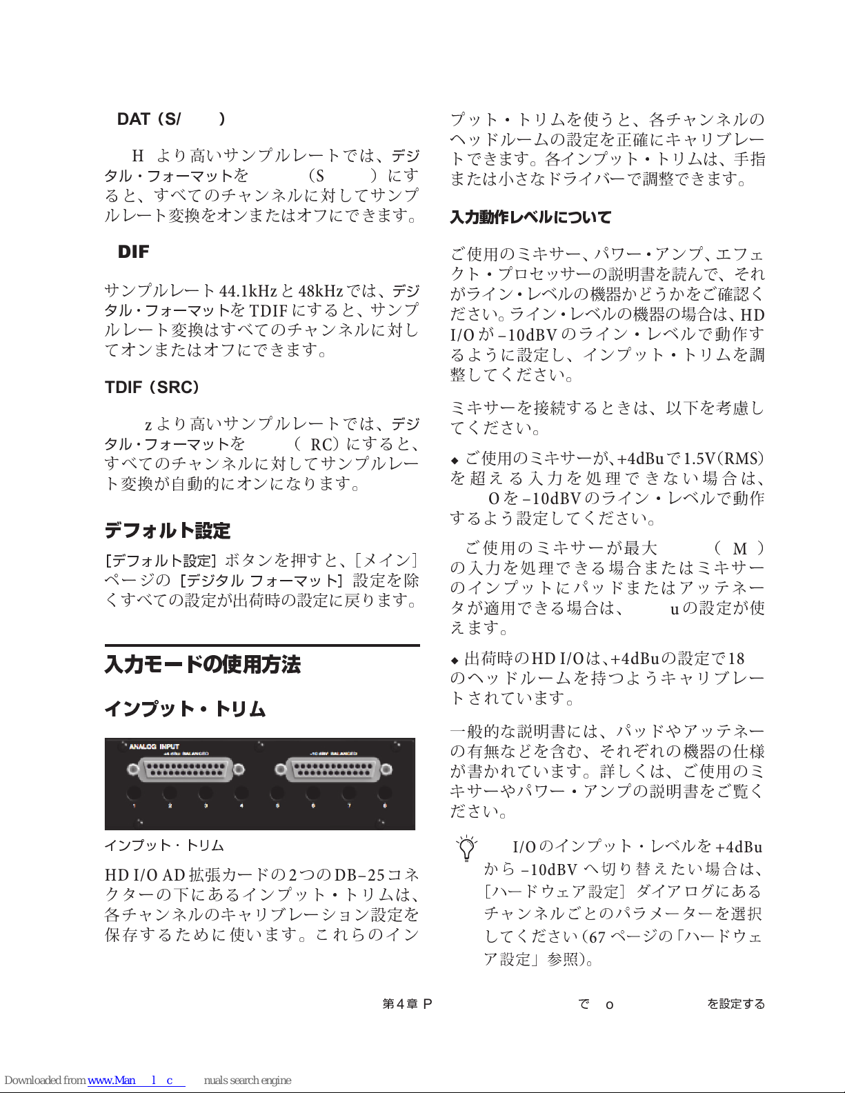
ADAT(S/MUX
48kHz
タル・フォーマット
ると、すべてのチャンネルに対してサンプ
ルレート変換をオンまたはオフにできます。
より高いサンプルレートでは、
)
を
ADAT(S/MUX
デジ
)にす
プット・トリムを使うと、各チャンネルの
ヘ
ッドルームの設定を正確にキャリブレー
トできます。各インプット・トリムは、
または小さなドライバーで
入力動作レベルについて
調整
できます。
手指
TDIF
サンプルレート
タル・フォーマット
ルレート変換はすべてのチャンネルに対し
てオンまたはオフにできます。
TDIF(SRC
48kHz
タル・フォーマット
すべてのチャンネルに対してサンプルレー
ト変換が自動的にオンになります。
より高いサンプルレートでは、
44.1kHzと48kHz
を
TDIF
)
を
TDIF(SRC
にすると、サン プ
では、
)にすると、
デジ
デジ
デフォルト設定
[デフォルト設定]
ページの
くすべての設定が
[デジタル フォーマット]
ボ
タンを押すと、[メイン
設定を
出荷
時の設定に戻ります。
除
ご使用のミキサー、パワー・アンプ、エフェ
クト・プロセッサーの説明書を
がライン・レベルの機器
ださい。ライン・レベルの機器の場合は、
が
I/O
るように設定し、インプット・トリムを
整
ミキサーを接続するときは、以下を
てください。
を
–10dBV
してください。
ご使用のミキサーが、
超え
る入力を
のライン・レベルで動作す
HDI/Oを–10dBV
するよう設定してください。
]
ご使用のミキサーが最大
の入力を
のインプットにパッドまたはアッテネー
タが適用できる場合は、
え
ます。
処理
できる場合またはミキサー
かどうか
+4dBuで1.5V(RMS
処理
できない場合は、
のライン・レベルで動作
+4dBu
読ん
15.5V(RMS
で、それ
をご確認く
HD
調
考慮
し
の設定が使
)
)
入力モードの使用方法
インプット・トリム
インプット・トリム
HD I/O AD
クターの下にあるインプット・トリムは、
各チャンネルのキャリブレーション設定を
保存するために使います。これらのイン
拡張カードの2つの
DB–25
コネ
第4章
Pro Tools | HD Software でPro Tools | HD I/O
出荷
時の
HD I/O
のヘッドルームを持つようキャリブレー
トされています。
一
般的
な説明書には、パッドやアッテネー
の
有無など
が書かれています。詳しくは、ご使用のミ
キ
サーやパワー・アンプの説明書をご覧く
ださい。
HD I/O
から
[ハードウェア設定]ダイアログにある
チャンネルごとのパラメーターを選択
してください(
ア設定」参照)。
を含む、それぞれの機器の
のインプット・レベルを
–10dBV
は、
+4dBu
の設定で
18dB
仕様
+4dBu
へ切り替えたい場合は、
ページの「ハードウェ
67
を設定する
77
Page 82

78
Pro Tools | HD I/O
ガイド
Page 83
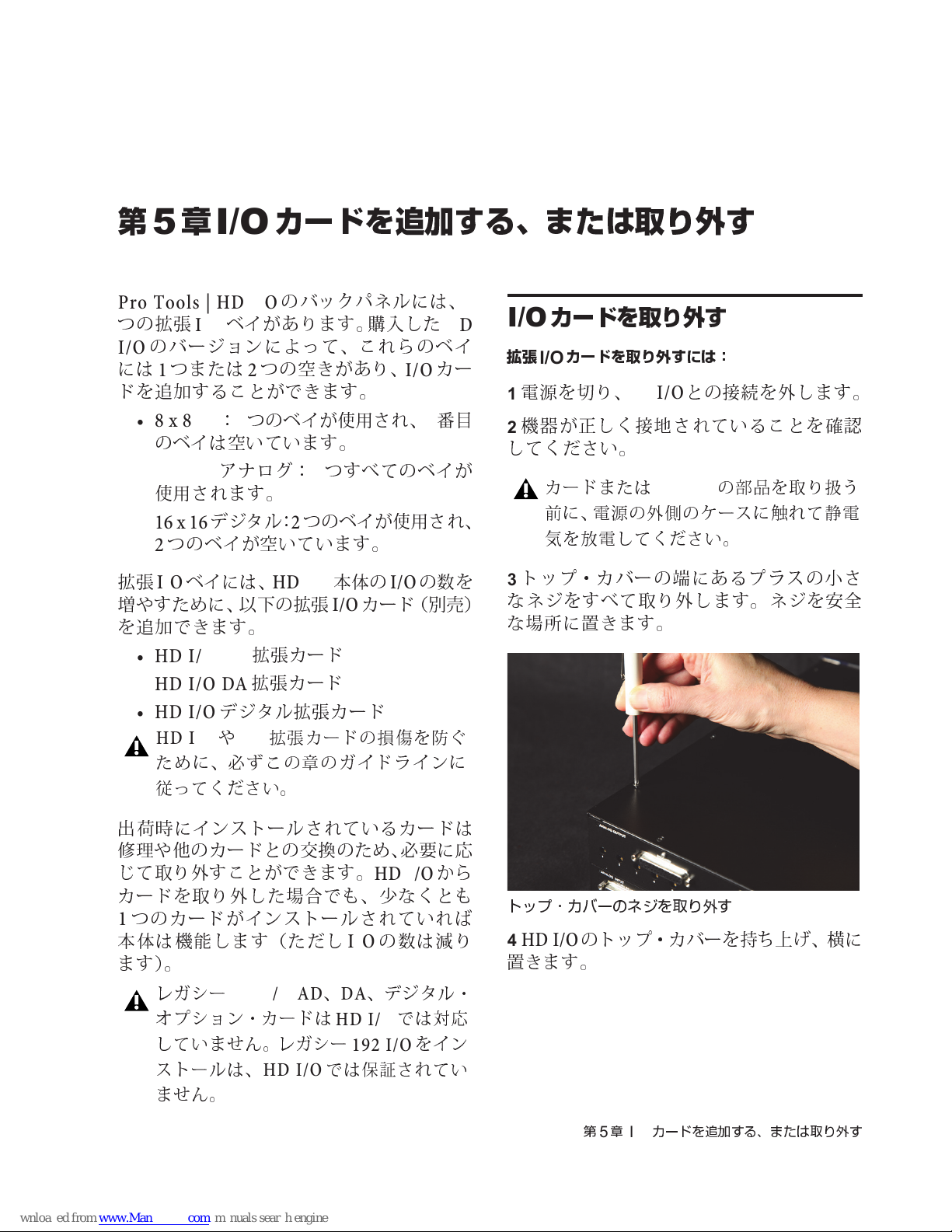
第
5
章
I/O
カードを追加する、または取り外す
Pro Tools | HD I/O
つの拡張
のバージョンによって、これらのベイ
I/O
には1つまたは2つの空きがあり、
ドを追加することができます。
ベイがあります。購入した
I/O
• 8 x 8 x 8:3
のベイは空いています。
•16 x 16
使用されます。
• 16 x 16
つのベイが空いています。
2
拡張
I/O
増
やすために、以下の拡張
を追加できます。
アナログ:4つすべてのベイが
デジタル:2つのベイが使用され、
ベイには、
•HD I/O AD
•HD I/O DA
•HD I/O
デジタル拡張カード
HD I/OやI/O
ために、必ずこの章のガイドラインに
従ってください。
のバックパネルには、
つのベイが使用され、4番目
HD I/O
拡張カード
拡張カード
拡張カードの損傷を防ぐ
本体の
カード(
I/O
I/O
I/O
の数を
別売
HD
カー
4
カードを取り外す
I/O
拡張
1
2
してください。
3
なネジをすべて取り外します。ネジを安全
)
な
カードを取り外すには:
I/O
電源を切り、
機器が正しく接地されていることを確認
カードまたは
前に、電源の外側のケースに触れて静電
気を放電してください。
トップ・カバーの端にあるプラスの小さ
場所に置
HDI/O
きます。
との接続を外します。
HD I/O
の部品を取り扱う
出荷
時にインストールされているカードは
修理や他
じて取り外すことができます。
カードを取り外した場合でも、少なくとも
つのカードがインストールされ ていれ
1
本体は機能します(ただし
ます)。
のカードとの交換のため、必要に応
レガシー
オプション・カードは
していません。レガシー
ストールは、
ません。
192 I/O AD、DA
HD I/O
か
HD I/O
の数は減り
I/O
、デジタル・
HD I/O
では対応
192 I/O
では保証されてい
ら
ば
をイン
トップ・カバーのネジを取り外す
HD I/O
4
置
きます。
のトップ・カバーを
第5章
カードを追加する、または取り外す
I/O
持ち上げ、横
に
79
Page 84
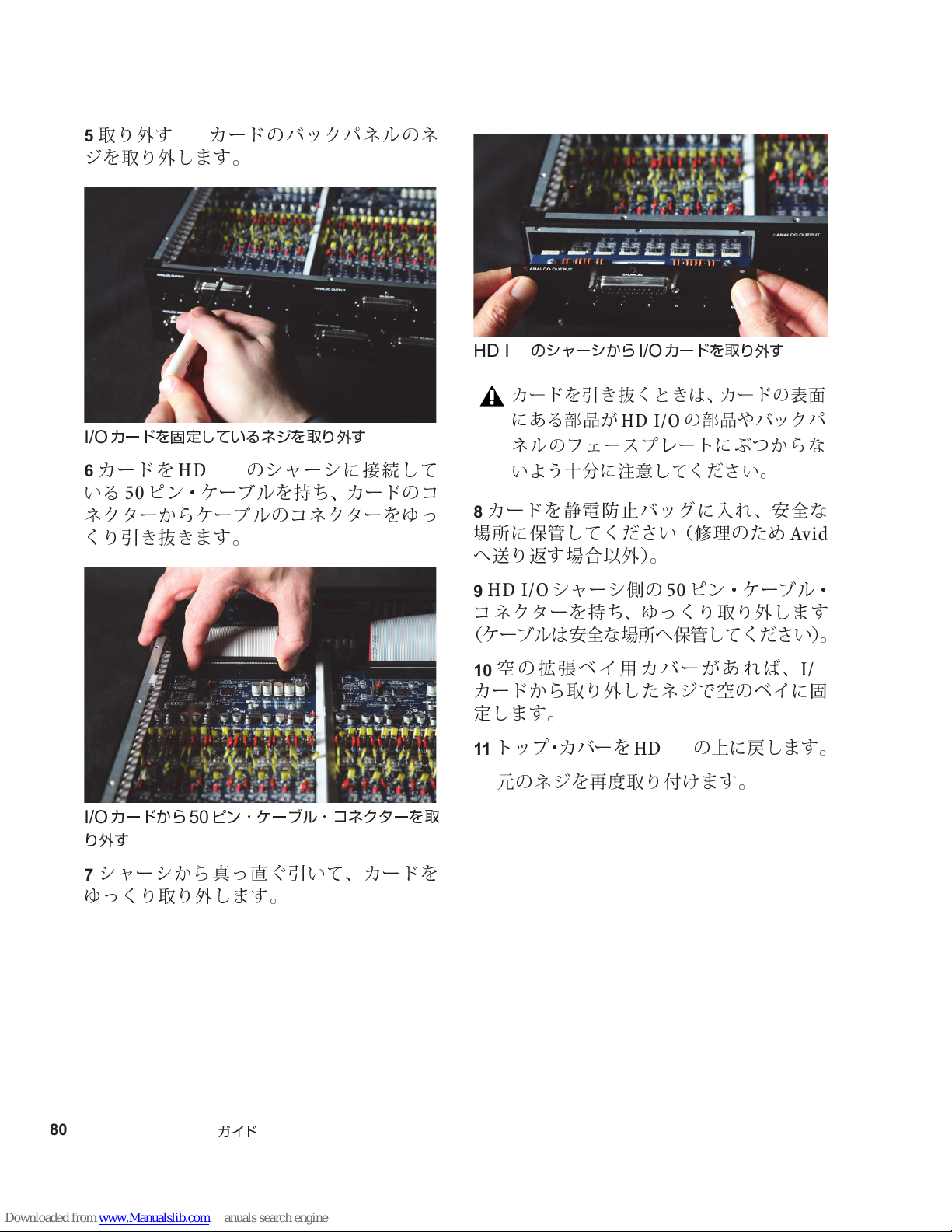
取り外す
5
カードのバックパネルのネ
I/O
ジを取り外します。
カードを固定しているネジを取り外す
I/O
カードを
6
HD I/O
いる50ピン・ケーブルを
のシャーシに接続して
持ち
、カードのコ
ネクターからケーブルのコネクターをゆっ
くり引き抜きます。
HD I/O
8
場所
のシャーシから
カードを引き抜くときは、カードの表面
にある部品が
ネルのフェースプレートにぶつか らな
いよう十分に注意してください。
カードを静電防止バッグに入れ、安全な
に保管してください(
カードを取り外す
I/O
HD I/O
の部品やバックパ
修理
のため
へ送り返す場合以外)。
HD I/O
9
コ ネクターを
(ケーブルは安全な
空
10
シャーシ側の50ピン・ケーブ ル・
持ち、ゆ
っくり取り外します
場所
へ保管してください)。
の拡張ベイ用カバーがあれば、
カードから取り外したネジで空のベイに
定します。
トップ・カバーを
11
元
のネジを
12
HD I/O
再度
取り付けます。
の上に戻します。
Avid
I/O
固
カードから50ピン・ケーブル・コネクターを取
I/O
り外す
シャーシから真っ直ぐ引いて、カ ード を
7
ゆ
っくり取り外します。
80
Pro Tools | HD I/O
ガイド
Page 85
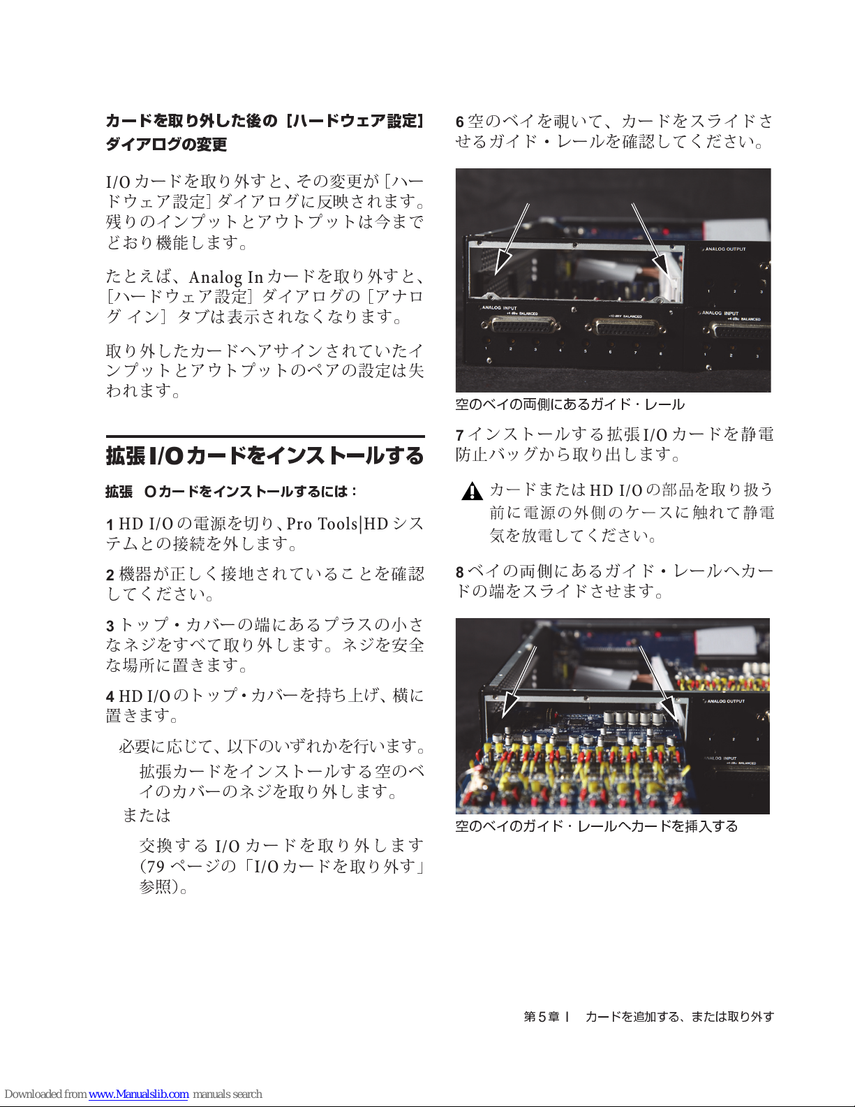
カードを取り外した後の[ハードウェア設定]
ダイアログの変更
カードを取り外すと、その変更が[ハー
I/O
ドウェア設定]ダイアログに
残
りのインプットとアウトプットは今まで
ど
おり機能します。
たと
えば
、
Analog In
[
ハードウェア設定]ダイアログの[アナロ
グ イン]タブは表示されなくなります。
取り外したカードへアサインされていたイ
ンプットとアウトプットのペアの設定は
わ
れます。
カードを取り外すと、
反映
されます。
失
空
のベイを覗いて、カードをスライドさ
6
せ
るガイド・レールを確認してください。
空のベイの両側にあるガイド・レール
拡張
拡張
I/O
HD I/O
1
テムとの接続を外します。
機器が正しく接地されていることを確認
2
してください。
トップ・カバーの端にあるプラスの小さ
3
なネジをすべて取り外します。ネジを安全
な
場所に置
HD I/O
4
置
きます。
必
要に応じて、以下のいずれかを行います。
5
拡張カードをインストールする空のベ
•
イのカバーのネジを取り外します。
または
交
•
(
参照)。
カードをインストールする
I/O
カードをインストールするには:
の電源を切り、
きます。
のトップ・カバーを
換する
ページの「
79
I/O
Pro Tools|HD
持ち上げ、横
カードを取り外します
カードを取り外す」
I/O
シス
に
インストールする拡張
7
防止バッグから取り出します。
カードまたは
前に電源の外側のケースに触 れて静電
気を放電してください。
ベイの
8
ドの端をスライドさせます。
空のベイのガイド・レールへカードを挿入する
両側
HD I/O
にあるガイド・レールへカー
カードを静電
I/O
の部品を取り扱う
第5章
カードを追加する、または取り外す
I/O
81
Page 86
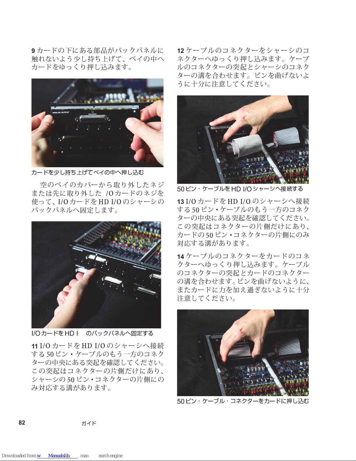
カードの下にある部品がバックパネルに
9
触
れないよう少し
カードをゆっくり押し
カードを少し持ち上げてベイの中へ押し込む
空
のベイのカバーから取り外したネジ
10
または先に取り外した
使って、
I/O
カードを
持ち上げ
込み
I/O
HD I/O
て、ベイの中へ
ます。
カードのネジを
のシャーシの
バックパネルへ固定します。
ケーブルのコネクターをシャーシのコ
12
ネクターへゆっくり押し
ルのコネクターの
ターの溝を合
うに
十分に注意
ピン・ケーブルを
50
カードを
I/O
13
突起
わせ
ます。ピンを
してください。
HD I/O
HD I/O
込み
ます。ケーブ
とシャーシのコネク
曲げ
ないよ
シャーシへ接続する
のシャーシへ接続
する50ピン・ケーブル のもう一方のコネク
ターの
この
カードの50ピン・コネ クターの
中央
にある
突起
はコネクターの
突起
を確認してください。
片側
だけにあり、
片側
にの
み
対応する溝があります。
I/O
11
カードを
カードを
I/O
HD I/O
のバックパネルへ固定する
HD I/O
のシャーシへ接続
する50ピン・ケーブルのもう一方のコネク
ターの
この
中央
にある
突起
はコネクターの
突起
を確認してください。
片側
だけにあり、
シャーシの50ピン・コ ネクターの
み
対応する溝があります。
82
Pro Tools | HD I/O
ガイド
片側
にの
ケーブルのコネクターをカードのコネ
14
クターへゆっくり押し
のコネクターの
の溝を合
わせ
突起
ます。ピンを
またカードに力を加
注意
してください。
ピン・ケーブル・コネクターをカードに押し込む
50
込み
ます。ケーブル
とカードのコネクター
曲げ
ないように、
え過ぎ
ないように
十分
Page 87
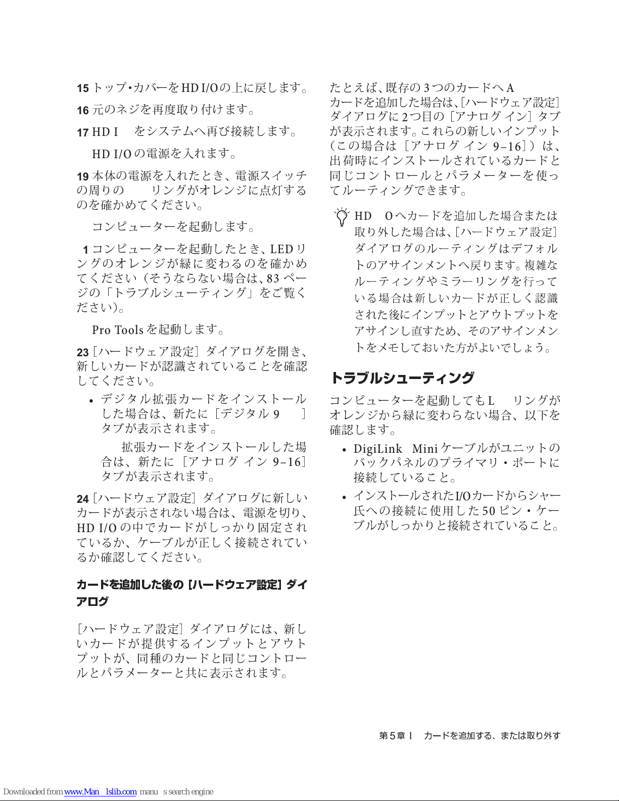
トップ・カバーを
15
元
のネジを
16
HDI/O
17
HD I/O
18
本体の電源を入れたとき、電 源スイッチ
19
の周りの
のを確かめてください。
コンピューターを起動します。
20
コンピューターを起動したとき、
21
ングのオレンジが緑に変わるのを確かめ
てください (そうならない場合は、
ジの「トラブルシューティング」をご覧く
ださい)。
ProTools
22
[
ハードウェア設定]ダイアログを開き、
23
新しいカードが認識されていることを確認
してください。
をシステムへ再び接続します。
の電源を入れます。
LED
を起動します。
HD I/O
再度
取り付けます。
リングがオレンジに
の上に戻します。
点灯
する
リ
LED
ペー
83
たと
えば、既存
カードを追加した場合は、[ハードウェア設定
ダイアログに2つ目の[アナログ イン]タブ
が表示されます。これらの新しいインプット
(この場合は[アナログ イン
出荷
時 にインストールされているカー ドと
同じコントロールとパラメーターを使っ
てルー ティングできます。
HD I/O
取り外した場合は、[ハードウェア設定]
ダイアログのルーティングはデフォル
トのアサインメントへ戻ります。複雑な
ルーティングやミラーリングを行って
いる場合は新しいカードが正しく認識
された後にインプットとアウト プットを
アサインし直すため、そのアサイ ンメン
トをメモしておいた方がよいでしょう。
の3つのカードへ
へカードを追加した場合または
Analog In
9–16
]
)は、
トラブルシューティング
]
デジタル拡張カードをインストール
•
した場合は、新たに[デジタル
タブが表示されます。
•AD
[
24
カードが表示されない場合は、電源を切り、
HD I/O
ているか、ケーブルが正しく接続されてい
るか確認してください。
カードを追加した後の[ハードウェア設定]ダイ
アログ
[
ハードウェア設定]ダイアログには、新し
いカードが提供するインプットとアウト
プットが、同種のカードと同じコントロー
ルとパラメーターと共に表示されます。
拡張カードをインストールした
合は、新たに[アナログ イン
タブが 表示されます。
ハードウェア設定]ダイアログに新しい
の中でカードがしっかり固定され
9–16
9–16
場
コンピューターを起動しても
]
オレンジから緑に変わらない場合、以下を
確認します。
ケーブルがユニットの
I/O
]
• DigiLink Mini
バックパネルのプライマリ・ポートに
接続していること。
インストールされた
•
氏
への接続に使用した50ピン・ケー
ブルがしっかりと接続されていること。
LED
カードからシャー
リングが
第5章
カードを追加する、または取り外す
I/O
83
Page 88

84
Pro Tools | HD I/O
ガイド
Page 89
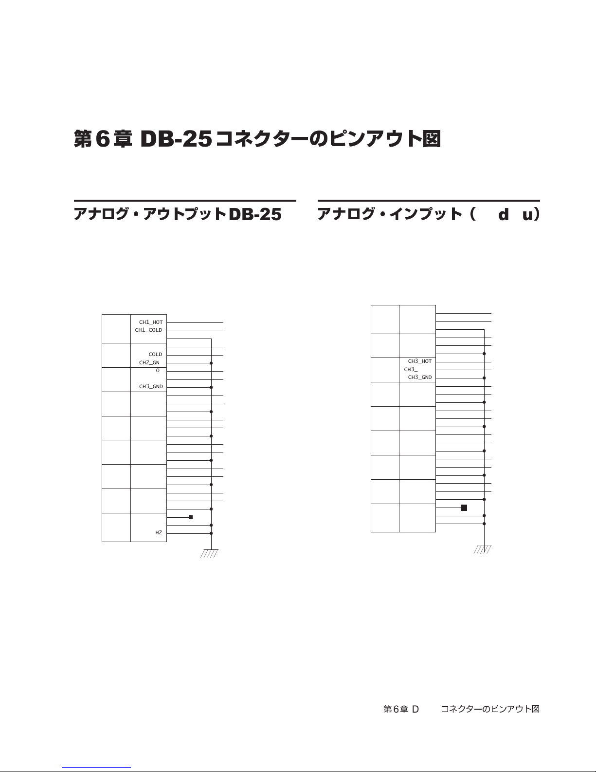
第
MH2
CH1_COLD
CH1_HOT
CH2_GND
CH2_COLD
CH3_GND
CH3_HOT
CH3_COLD
CH4_GND
CH4_HOT
CH4_COLD
CH8_COLD
CH7_COLD
CH7_HOT
CH7_GND
CH6_COLD
CH6_HOT
CH6_GND
CH5_GND
CH5_HOT
CH5_COLD
CH8_GND
NC_1
CH1_GND
CH2_HOT
CH8_HOT
MH1
1
8
7
6
5
4
3
2
27
12
24
11
23
22
21
9
8
7
20
14
3
15
16
17
4
5
19
18
6
2
13
25
10
1
26
MH2
CH1_COLD
CH1_HOT
CH2_GND
CH2_COLD
CH3_GND
CH3_HOT
CH3_COLD
CH4_GND
CH4_HOT
CH4_COLD
CH8_COLD
CH7_COLD
CH7_HOT
CH7_GND
CH6_COLD
CH6_HOT
CH6_GND
CH5_GND
CH5_HOT
CH5_COLD
CH8_GND
NC_1
CH1_GND
CH2_HOT
CH8_HOT
MH1
1
8
7
6
5
4
3
2
27
12
24
11
23
22
21
9
8
7
20
14
3
15
16
17
4
5
19
18
6
2
13
25
10
1
26
6
章
DB-25
コネクターのピンアウト図
アナログ・アウトプット
DB-25
アナログ・インプット(
DB-25
第6章
DB-25
コネクターのピンアウト図
+4dBu
)
85
Page 90
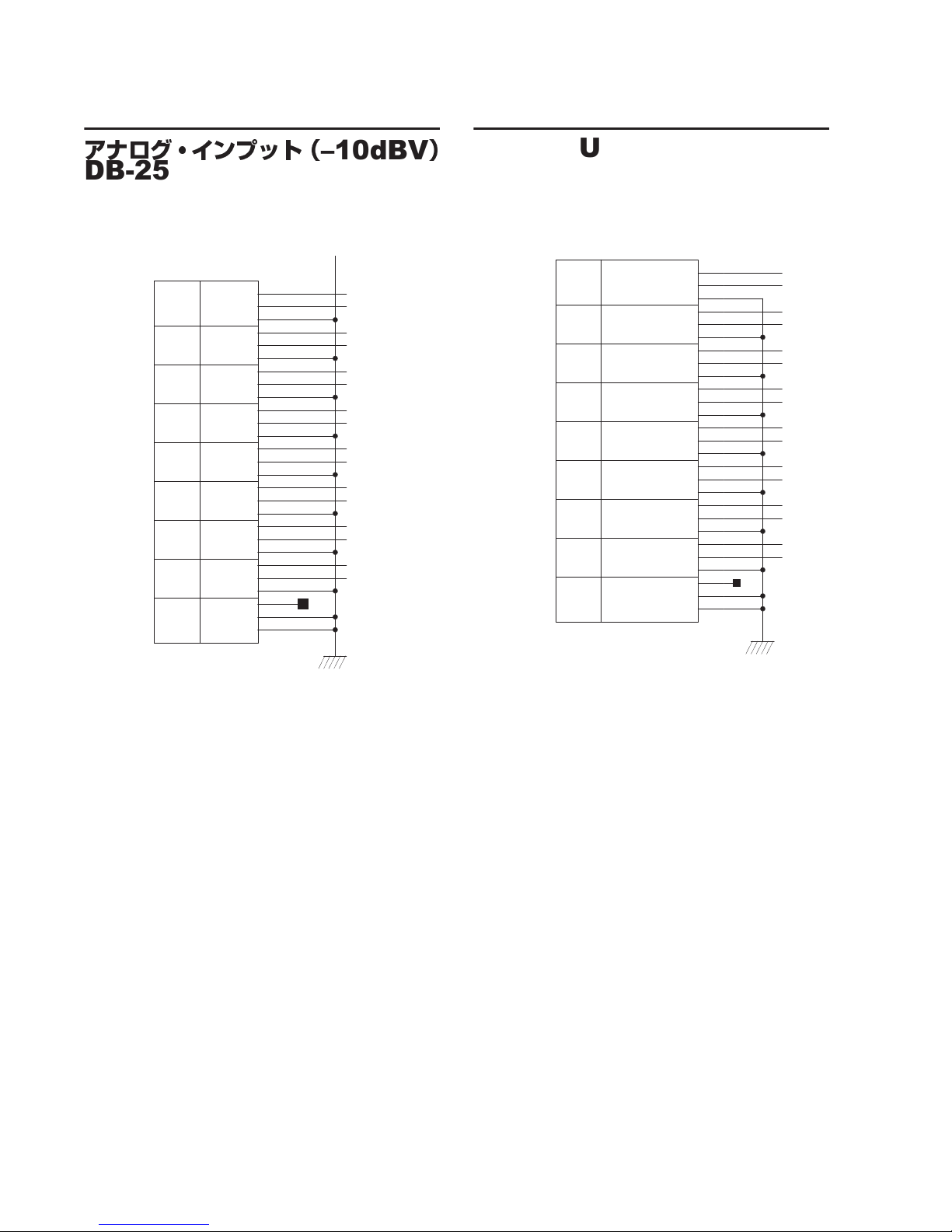
アナログ・インプット(
MH2
CH1_COLD
CH1_HOT
CH2_GND
CH2_COLD
CH3_GND
CH3_HOT
CH3_COLD
CH4_GND
CH4_HOT
CH4_COLD
CH8_COLD
CH7_COLD
CH7_HOT
CH7_GND
CH6_COLD
CH6_HOT
CH6_GND
CH5_GND
CH5_HOT
CH5_COLD
CH8_GND
NC_1
CH1_GND
CH2_HOT
CH8_HOT
MH1
1
8
7
6
5
4
3
2
27
12
24
11
23
22
21
9
8
7
20
14
3
15
16
17
4
5
19
18
6
2
13
25
10
1
26
MH2
CH12_RCV_COLD
CH12_RCV_HOT
CH34_RCV_GND
CH34_RCV_COLD
CH56_RCV_GND
CH56_RCV_HOT
CH56_RCV_COLD
CH78_RCV_GND
CH78_RCV_HOT
CH78_RCV_COLD
CH78_XMT_COLD
CH56_XMT_COLD
CH56_XMT_HOT
CH56_XMT_GND
CH34_XMT_COLD
CH34_XMT_HOT
CH34_XMT_GND
CH12_XMT_GND
CH12_XMT_HOT
CH12_XMT_COLD
CH78_XMT_GND
NC_1
CH12_RCV_GND
CH34_RCV_HOT
CH78_XMT_HOT
MH1
XMT
XMT
XMT
7-8
5-6
3-4
RCV
RCV
RCV
1-2
RCV
3-4
5-6
7-8
1-2
XMT
27
12
24
11
23
22
21
9
8
7
20
14
3
15
16
17
4
5
19
18
6
2
13
25
10
1
26
DB-25
–10dBV
AES/EBU DB-25
)
Pro Tools | HD I/O Guide86
Page 91

TDIF DB-25
GND_AGND_A
GND_C
22PF22PF
GND_C
MH2
CH12_RCV_DATA
GND3
CH56_RCV_DATA
CH12_XMT_DATA
CH78_RCV_DATA
GND4
GND6
GND5
CH34_XMT_DATA
XMT_FS1
RCV_FS0
RCV_FS1
XMT_LRCK
RCV_LRCK
RCV_EMPHASIS
CH56_XMT_DATA
GND7
XMT_FS0
CH34_RCV_DATA
GND2
XMT_EMPHASIS
MH1
DB25F_RA_TDIF
GND1
CH78_XMT_DATA
GND8
GND9
7-8
CLK+CTRL
1-2
3-4
5-6
1-2
3-4
5-6
RCV DATAXMT DATA
RCV
CLK+CTRL
XMT
7-8
GND_C
27
13
23
11
1
10
22
15
14
2
19
20
8
5
9
21
3
16
6
12
24
18
26
25
4
17
7
NC=
NC=
NC=
FB30 FB31
第6章
DB-25
コネクターのピンアウト図
87
Page 92

Pro Tools | HD I/O Guide88
Page 93
第
7
章
HD I/O
のキャリブレーション・モードの説明
Pro Tools | HD I/O
のインプットとアウトプットのレベル
I/O
をミキシング・コンソールのレベルへキャ
リブレートするほうがよい場合がありま
す。
HDI/O
のインプット、
それぞれが正しいキャリブレーションを行
うためのトリム・ポットを
HD I/O
レベルで
ムを持つよう(最大入出力
リブレートされています。
HD I/O
を
この章で説明する
さい。
には、
+4dBu
+4dBu
は、
出荷
+4dBu
やスタジオの他のコンポーネント
再キ
ャリブレートする必要がある場合は、
を使用する前に、
のインプット、
のアウトプットがあり、
備え
ています。
時には
の上に
+4dBu
18dB
の入力動作
のヘッドルー
+22dBu
調整
方法を使ってくだ
HD
–10dBV
)キャ
ヘッドルーム(
ヘ
ッドルームの概念は、アナログ機器とデ
ジタル機器で少し異なります。
アナログ
上に一定のヘッドルームを持っています。ア
ナログのレコーダーへ
を送った場合、ヘッドルームのゆとりがあ
るため、テープが
は穏やかなもので、その
ドを好ましく思う人もいます。
デジタル
ク・レンジ(dBフルスケール)を
号を
ジタル機器をの最大入力レベルを
と、クリッピングが
しくないデジタル
ほとんど
デジタル機器は、入力のダイナミッ
許容
することができま
Headroom
のアナログ機器は、
より大きい信号
0VU
飽和状態
発生
歪みの原因
になってもそれ
圧縮
せん。信
し、
)
0VU
されたサウン
超える信
号がデ
超え
耳障
りで望ま
になります。
の
る
キャリブレーションの方法
キャリブレーションについて
デジタル録音機器のレベルのキャリブレー
ションとアナログ録音機器のレベルのキャ
リブレーションは異なります。アナログ機
器とは異なり、一般のデジタル機器には入
出
力の公称レベルに
レベルの設定がありま
HDI/O
(dBフルスケール)の下、何デシベルかで
メーターをキャリブレートします。
の様なインターフェースでは、ピーク
相当
せん
する標準の「
。その
代わ
」
0VU
りに、
アナログ
シング・コンソールの出力レベルへキャリ
ブレートするには、一
ンをコンソールからアナログ・デッキへ
0VU
メーターが
アナログ機器の入力レベルをミ
般的
には
で送り、レコーディング・デッキの
第7章
0VU
HD I/O
を指すよう
のキャリブレーション・モードの説明
調整
のトー
1kHz
します。
キ
89
Page 94
デジタル
器では、ヘッドルームを持たせるために、
コンソールからの
のゼロ(dBフルスケール)から
け少なくなるよう
たと
ドルームを持たせるためには、入力した
HD I/O
えば
、
HDI/Oで0VU
0VU 1kHz
調整
します。
あれば、
+4dBu
ていることを想定しているため、その機器ま
たはコンソールからの
には公
–18dBFS
の機器またはコンソールと共に使っ
称
+4dBu
HD I/O
ご使用の
ProTools
キ
ャリブレーション・セッション(
HD I/O
に付属しているいずれかの
のようなデジタル録音機
のトーンが
0VU
目的の値
調整
します。
の上に
のトーンが
18dB
–12dBFS
のヘッドルームが必要で
へ
調整
します(
0 VU
の信号と同等です)。
12dB
を指すよう
HD I/O
の信号は、実
をキャリブレートする
をキャリブレートするには、
Pro Tools
HD I/O
だ
のヘッ
を
際
HDI/O
Utilities/Calibration Mode Session/HD IO
Calibration Session
使用します。より多くのチャンネルの
が必要な場合は、このセッションのイン
プットとアウトプットのアサインメントを
変更するか、またはこれらのセッションをも
とに独自のキャリブレーション・テンプレー
トを作成します。
フォルダー)の一つを
調整
システムに
る場合、フェーダーがサイレントとなる
よう、
モードを有効にする前に
トウェアの「
を無効にしてください。「
select track
を確認するには、[
ンドウを開き、[全般]タブに移動して、
設定が無効になっていることを確認し
ます。必要に応じて[
]をクリックして無効にします。
track
キャリブレーション・モードを終了し
た後、必ず[
設定を必要に応じて再度有効にしてく
ださい。
キャリブレーションを始め る前にモニ
ターのレベルを下げてください。
Generator
入されると信号を送り続けます。
セッションを作成して
るには:
ProTools
1
成します。
EUCON
Pro Tools
Auto-bank to selected track
」が無効になっていること
Auto-bank to selected track
プラグインは、トラックへ挿
を起動し、新規セッションを作
コントローラーがあ
のキャリブレーション・
EuControl
Auto-bank to
EuControl
設定]ウィ
Auto-bank to selected
HD I/O
をキャリブレートす
ソフ
」
]
Signal
以下に、このキャリブレーション・セッシ ョ
ンがどのように作成されたかを説明します。
90
Pro Tools | HD I/O
ガイド
[設定](
2
を選択し、
クします。
目的のキ
3
レベルをdB単位
ベルが一
入力する必要はありま
[OK]
4
[トラック](
5
して新しいモノラル・オーディオ・トラッ
クを作成します。
Setup
[操作](
般的
をクリックします。
)[初期設定](
Operation
ャリブレーション・リファレンス・
で入力します。
です (ここにマイナス記号を
せん
Track) >
[新規](
Preferences
)
タブをクリッ
–18dB
)。
)
New
のレ
を選択
)
Page 95
トラックに
6
ンを挿入します。
[
Signal Generator
7
ベルを設定します。キャリブレーション・
リファレンス・レベルとして入力した値と
同じ値(
Signal Generator
8
定します。一
他
の周波数でも
500Hz
[
9
に設定します。
10
ルーティングします。前述のキャリブレー
ション・テンプレートでは、[バス1]
前が
11
プットごとにモ
クを作成します。これらの
トラックのアウトプットを
のアウトプットへアサインします。
12
トを[バス1]
の場合は
13
モ
ます。これらの
のインプットを
トへアサインします。次に、これら の
インプット・トラックのアウトプットを
使用のバ ス・ペア(バ ス
します。テンプレート・セッションのバス
名は
メイン・アウトプット
ときにフィードバックが
ます。
もまた一
Signal Generator
トラックのアウトプットを[バス1]
[
1k Tone
キ
ャリブレートする
AUX
キ
ャリブレートするインプットごとに
ノ
AUX
[
Null
[
Signal Generator
]
プラグインの出力レ
–18dB
など)にしてください。
の周波数を
般的
なのは
問題
ありま
般的
です。
]の信
]
へ変更されています。
1000Hz
HDI/O
ノ
インプット・トラッ
AUX
AUX
インプット・トラックのインプッ
(テンプレート・セッション
[
1k Tone
インプット・トラックを作成し
]
)へ設定します。
インプット・トラッ ク
AUX
のそれぞれのインプッ
I/O
]
プラグイ
1000Hz
せん
。
250Hz
号の
波形を正弦
のアウト
インプット・
のそれぞれ
I/O
に設
ですが、
や
へ
の名
AUX
未
など)へ設定
3–4
]と[
Out
]
です。これによって、
をモニターする
1–2
発生
するのを防
げ
外部の
14
トへ接続します (キャリブレートするアウ
トプットごとに)。
Pro Tools
15
Option-
(
Windows
定します。
16
リム・ポットを回し、外部の
0VU
ドライバーの頭にトリム・ポットを保持す
るプラスチックの筒が付いたツイーカーの
使用をお勧めします。ツイーカーは、電子部
品の
HD I/O
以下のいずれかの方法で
1
プットを
ます。
クリック(
小
さなマイナスのドライバーで
を指すようアウトプットを
販売店で扱
のインプットをキャリブレートするには:
• DB-25/DB-25
ケーブルを使用します。
•DB-25/XLR
接続します。
ProTools
2
リブレーション
を選択します。
キ
ャリブレートされていないすべてのト
ラックの名前が
の入力信号を受信している各
プット・トラックのボリューム・インジケー
ターが、キャリブレートされたアウトプッ
トから送られてくるリファレンス・レベル
(デフォルトは
メーターを
VU
のトラックのフェーダーを
)または
Mac
)して、デフォルトの
のアウトプッ
I/O
Alt-
クリック
0dB
I/O
メーターが
VU
調整
します。
っています。
のイン
端を相
HD I/O
ケーブルの
で、
[オプション](
モード](
点滅し始
HD I/O
のアウトプットへ接続し
ストレート・スルー・
XLR
Options)>
Calibration Mode
めます。また、外部
AUX
–18dB
)を表示します。
へ設
のト
[キャ
イン
互
)
第7章
HD I/O
のキャリブレーション・モードの説明
91
Page 96
マイナスの小さなドライバーまたは
3
イーカーで
トリム・ポットを
クパネル を正面にして、
見
ながらインプットをキャリブレートして
ください。
きない場合は、
でしょう。レベルが一致すると、トラックの
名前の
インジケーターがヘッドルームの値(デフォ
ルトは
各トラックの
の
矢印
入力されたレベルがリファレンス・レベ
•
ルより高いときは、下向きの
(⻘)します。この場合は、
プット・レベルを下げます。
入力されたレベルがリファレンス・レベ
•
ルより低いときは、上向きの
(赤)します。この場合は、
プット・レベルを上げます。
受信ピーク信号のレベルをキャリブレー
ション・リファレンス・レベルに一致する
よう正しく
ジケーターの
印は赤、下向き⽮印は⻘)。
フェーダーの上にあるのがピーク・ボリューム・
インジケーターです。このインジケーター
を見ると、設定したヘッドルームの値に対す
る差し引きがdB単位で分か
インジケーターに
れば、ヘッドルームの値の
–1.1dB
と表示されていれば、ヘッドルームの
-16.5
値
の
–18dB
HD I/O
Pro Tools
点滅が停止
[
–18.0
が、
調整が必
調整
矢印が点灯
下です。ピーク・インジケーターに
より
のインプット・レベルの
調整
します。
の画面を見ることがで
誰かに手伝
し、ピーク・ボリューム・
]
)を示します。
Automatch
要な方向を示します。
HD I/O
Pro Tools
ってもらうとよい
インジケーター
の画面を
矢印が点灯
I/O
矢印が点灯
I/O
した場合、
–19.1
Automatch
します(上向き
ります。ピーク・
と表示されてい
–18dB
+1.5dB
上です。
ツ
のバッ
のイン
のイン
イン
矢
より
アナログ・アウトプット・カードの
ジャンパーを切り替える
HD I/O
には、そのカードの8チャンネルのアウト
プットの
るジャンパーがあります。ジャンパーのデ
フォルトの設定は
+4dBu
する場合の設定です。
ただし、
アナログ・アウトプット・カードのジャン
パーをデフォルトの
ド用
ウトプット・チャンネル用のトリム・ポッ
トを
器が接続できるようにします。
アウトプット・カードのアウトプット・チャンネル用
のジャンパーを切り替えるには:
HD I/O
1
カードを取り外します(
を追加する、または取り外す」参照)。
カードを安定していて静電気が防止され
2
た表面に置きます。
ピンセットまたは
3
変更するアウトプット・チャンネルのジャ
ンパ ーを取り外 します。
用アナログ・アウトプッ ト・カー ド
[Hi]と[Lo]
レベルで動作する業務用機器を使用
–10dBV
[Lo]へ切り替え
調整
してさらに
のシャーシからアウトプット・
の機器を使用する場合は、
の設定を切り
[Hi]
[Hi]か
4dB
先細
です。これは、
ら
–6dB
ます。次に、そのア
下げ、
第5章
–10dBV
「
I/O
ペンチを使って
替え
のパッ
の機
カード
完了したら、
4
リブレーション
をオフにします。
92
Pro Tools | HD I/O
[オプション](
モード](
ガイド
Calibration Mode
Options)>
[キャ
)
Page 97
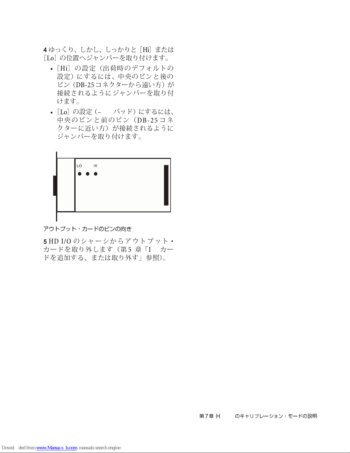
ゆ
っくり、しかし、 しっかりと
4
[Lo]の位置
•[Hi
設定)にするには、
ピン(
へジャンパーを取り付けます。
]
の設定(
DB-25
出荷
時のデフォルトの
中央
のピンと後の
コネクターから遠い方)が
接続されるようにジャンパーを 取り付
けます。
]
•[Lo
中央
の設定(
のピンと前のピン(
パッド)にするには、
–6dB
クターに近い方)が接続されるように
ジャンパーを取り付けます。
[Hi]
DB-25
または
コネ
アウトプット・カードのピンの向き
HD I/O
5
カードを取り外します(
のシャーシからアウトプット・
第5章
「
I/O
カー
ドを追加する、または取り外す」参照)。
第7章
HD I/O
のキャリブレーション・モードの説明
93
Page 98

94
Pro Tools | HD I/O
ガイド
Page 99
Appendix A: Compliance Information
Proposition 65 Warning
Environmental Compliance
Disposal of Waste Equipment by Users
in the European Union
This symbol on the product or its packaging indicates that this
product must not be disposed of with other waste. Instead, it
is your responsibility to dispose of your waste equipment by
handing it over to a designated collection point for the recycling
of waste electrical and electronic equipment. The separate
collection and recycling of your waste equipment at the time of
disposal will help conserve natural resources and ensure that
it is recycled in a manner that protects human health and the
environment. For more information about where you can drop
off your waste equipment for recycling, please contact your
local city recycling office or the dealer from whom you purchased
the product.
This product contains chemicals, including lead,
known to the State of California to cause cancer
and birth defects or other reproductive harm.
Wash hands after handling.
Perchlorate Notice
This product may contain a lithium coin battery. The State of
California requires the following disclosure statement: “Perchlorate
Material – special handling may apply, See
www.dtsc.ca.gov/hazardouswaste/perchlorate.”
Recycling Notice
Appendix A: Compliance Information 95
Page 100
EMC (Electromagnetic
Compliance)
Avid declares that this product complies with the following standards
regulating emissions and immunity:
• FCC Part 15 Class A
• EN55103-1 E4
• EN55103-2 E4
• AS/NZS CISPR 22 Class A
• CISPR 22 Class A
FCC Compliance for United States
Communication Statement
Note: This equipment has been tested and found to comply with
the limits for a Class A digital device, pursuant to part 15 of
the FCC Rules. These limits are designed to provide reasonable
protection against harmful interference when the equipment
is operated in a commercial environment. This equipment
generates, uses, and can radiate radio frequency energy and,
if not installed and used in accordance with the instruction
manual, may cause harmful interference to radio communications.
Operation of this equipment in a residential area is likely to
cause harmful interference in which case the user will be
required to correct the interference at his own expense.
Any modifications to the unit, unless expressly approved by Avid,
could void the user's authority to operate the equipment.
Australia and New Zealand EMC
Regulations
Canadian Compliance
This Class A digital apparatus meets all requirements of the
Canadian Interference-Causing Equipment Regulations.
Cet appareil numérique de la classe A respecte toutes les
exigences du Règlement sur le material brouilleur du Canada.
European Union Declaration of
Conformity
(EMC and Safety)
Avid is authorized to apply the CE (Conformité Europénne) mark
on this compliant equipment thereby declaring conformity to EMC
Directive 2004/108/EC and Low Voltage Directive 2006/95/EC.
Argentina Conformity
Korean EMC Regulations
이 기기는 업무용(A급) 전자파적합기기로서 판
매자 또는 사용자는 이 점을 주의하시기 바라
며, 가정외의 지역에서 사용하는 것을 목적으로
합니다
.
Pro Tools | HD I/O Guide96
 Loading...