

Page 1

Avid® 3D
User’s Guide
make manage move | media
™
Avid
®
Page 2

Copyright and Disclaimer
Product specifications are subject to change without notice and do not represent a commitment on the part
of Avid Technology, Inc.
The software described in this document is furnished under a license agreement. You can obtain a copy of
that license by visiting Avid's Web site at www.avid.com. The terms of that license are also available in the
product in the same directory as the software. The software may not be reverse assembled and may be
used or copied only in accordance with the terms of the license agreement. It is against the law to copy the
software on any medium except as specifically allowed in the license agreement.
Avid products or portions thereof are protected by one or more of the following United States Patents:
4,746,994; 4,970,663; 5,045,940; 5,063,448, 5,245,432, 5,267,351; 5,309,528; 5,325,200; 5,355,450;
5,396,594; 5,440,348; 5,452,378; 5,467,288; 5,513,375; 5,528,310; 5,557,423; 5,577,190; 5,584,006;
5,627,765; 5,634,020; 5,640,601; 5,644,364; 5,654,737; 5,701,404; 5,724,605; 5,726,717; 5,729,673;
5,731,819; 5,745,637; 5,752,029; 5,754,180; 5,754,851; 5,781,188; 5,799,150; 5,812,216; 5,828,678;
5,842,014; 5,852,435; 5,889,532; 5,912,675; 5,930,797; 5,966,134; 5,977,982; 5,995,079; 5,999,190;
6,011,562; 6,014,150; 6,023,703; 6,031,529; 6,091,422; 6,154,221; 6,157,929; 6,160,548; 6,167,404;
6,192,388; 6,208,357; 6,226,005; 6,310,621; 6,317,142; 6,353,437; 6,400,368; 6,466,214; 6,469,702;
6,473,094; 6,539,163; 6,552,731; 6,553,140; 6,570,578; 6,573,898; 6,621,504; 6,664,966; 6,686,918;
D352,278; D392,267; D392,268; D392,269; D395,291; D396,853; D398,912. Other patents are pending.
No part of this document may be reproduced or transmitted in any form or by any means, electronic or
mechanical, including photocopying and recording, for any purpose without the express written permission
of Avid Technology, Inc.
Copyright © 2004 Avid Technology, Inc. and its licensors. All rights reserved. Printed in USA.
The Avid 3D application uses JScript and Visual Basic Scripting Edition from Microsoft Corporation.
Attn. Government User(s). Restricted Rights Legend
U.S. GOVERNMENT RESTRICTED RIGHTS. This Software and its documentation are “commercial
computer software” or “commercial computer software documentation.” In the event that such Software or
documentation is acquired by or on behalf of a unit or agency of the U.S. Government, all rights with
respect to this Software and documentation are subject to the terms of the License Agreement, pursuant to
FAR §12.212(a) and/or DFARS §227.7202-1(a), as applicable.
Trademarks
888 I/O, Adrenaline, AirPlay, AirSPACE, AirSPACE HD, AniMatte, AudioSuite, AudioVision, AutoSync, Avid,
Avid DNA, AVIDdrive, AVIDdrive Towers, Avid Mojo, AvidNet, AvidNetwork, AVIDstripe, Avid Unity,
Avid Xpress, AVoption, AVX, CamCutter, ChromaCurve, ChromaWheel, DAE, D-Fi, D-fx, Digidesign,
Digidesign Audio Engine, Digidesign Intelligent Noise Reduction, DigiDrive, Digital Nonlinear Accelerator,
DigiTranslator, DINR, dotXSI, D-Verb, Equinox, ExpertRender, FieldPak, Film Composer, FilmScribe,
FluidMotion, HIIP, HyperSPACE, HyperSPACE HDCAM, IllusionFX, Image Independence, Intraframe, iS9,
iS18, iS23, iS36, Lo-Fi, Magic Mask, make manage move | media, Marquee, Matador, Maxim, MCXpress,
Media Composer, MediaDock, MediaDock Shuttle, Media Fusion, Media Illusion, MediaLog,
Media Reader, Media Recorder, MEDIArray, MediaShare, Meridien, MetaSync, NaturalMatch, Nearchive,
NetReview, NewsCutter, Nitris, OMF, OMF Interchange, OMM, Open Media Framework,
Open Media Management, ProEncode, Pro Tools, QuietDrive, Recti-Fi, RetroLoop, rS9, rS18, Sci-Fi,
Softimage, Sound Designer II, SPACE, SPACEShift, Symphony, the Avid|DS logo, the XSI logo, Trilligent,
UnityRAID, Vari-Fi, Video Slave Driver, VideoSPACE, Xdeck, and XSI are either registered trademarks or
trademarks of Avid Technology, Inc. in the United States and/or other countries.
iNEWS, iNEWS ControlAir, and Media Browse are trademarks of iNews, LLC.
Digimation and Digimation Model Bank are either registered trademarks or trademarks of Digimation, Inc.
in the United States and/or other countries.
mental ray and mental images are registered trademarks of mental images GmbH & Co. KG in the U.S.A.
and some other countries. All other trademarks contained herein are the property of their respective
owners.
GOT FOOTAGE?
Editors — Filmmakers — Special Effects Artists — Game Developers — Animators — Educators —
Broadcasters — Content creators of every genre — Just finished an incredible project and want to
share it with the world?
2
Page 3

Send us your reels and we may use your footage in our show reel or demo!*
For a copy of our release and Avid’s mailing address, go to www.avid.com/footage.
*Note: Avid cannot guarantee the use of materials submitted.
Avid 3D User’s Guide• 0130-06217-01 • June 2004
3
Page 4

4
Page 5

Contents
Using This Guide. . . . . . . . . . . . . . . . . . . . . . . . . . . . . . . . . . . . . . . 25
Symbols and Conventions . . . . . . . . . . . . . . . . . . . . . . . . . . . . . . . . . . . . . . 26
If You Need Help. . . . . . . . . . . . . . . . . . . . . . . . . . . . . . . . . . . . . . . . . . . . . . 27
Accessing the Online Library . . . . . . . . . . . . . . . . . . . . . . . . . . . . . . . . . . . . 27
How to Order Documentation . . . . . . . . . . . . . . . . . . . . . . . . . . . . . . . . . . . . 28
Avid Educational Services. . . . . . . . . . . . . . . . . . . . . . . . . . . . . . . . . . . . . . . 28
Chapter 1 Getting Started . . . . . . . . . . . . . . . . . . . . . . . . . . . . . . . . . . . . . . . . 29
Starting Avid 3D . . . . . . . . . . . . . . . . . . . . . . . . . . . . . . . . . . . . . . . . . . . . . . 30
Starting with the Windows Start Menu . . . . . . . . . . . . . . . . . . . . . . . . . . 30
Starting from the Avid 3D Shortcut. . . . . . . . . . . . . . . . . . . . . . . . . . . . . 30
Starting from the Command Line . . . . . . . . . . . . . . . . . . . . . . . . . . . . . . 31
Avid 3D Startup Options. . . . . . . . . . . . . . . . . . . . . . . . . . . . . . . . . . . . . 31
Usage . . . . . . . . . . . . . . . . . . . . . . . . . . . . . . . . . . . . . . . . . . . . . . . 31
Command Line Options. . . . . . . . . . . . . . . . . . . . . . . . . . . . . . . . . . 32
Creating the First Project . . . . . . . . . . . . . . . . . . . . . . . . . . . . . . . . . . . . . . . 32
Exiting Avid 3D . . . . . . . . . . . . . . . . . . . . . . . . . . . . . . . . . . . . . . . . . . . . . . . 33
Chapter 2 Managing Projects and Scenes . . . . . . . . . . . . . . . . . . . . . . . . . . . 35
Types of Projects and Scenes . . . . . . . . . . . . . . . . . . . . . . . . . . . . . . . . . . . 36
Fixed-Camera Scenes . . . . . . . . . . . . . . . . . . . . . . . . . . . . . . . . . . . . . . 36
Free-Camera Scenes. . . . . . . . . . . . . . . . . . . . . . . . . . . . . . . . . . . . . . . 36
Projects . . . . . . . . . . . . . . . . . . . . . . . . . . . . . . . . . . . . . . . . . . . . . . . . . . . . . 37
The Project Manager . . . . . . . . . . . . . . . . . . . . . . . . . . . . . . . . . . . . . . . 37
The Project Structure . . . . . . . . . . . . . . . . . . . . . . . . . . . . . . . . . . . . . . . 37
Page 6

Contents
Creating a New Project . . . . . . . . . . . . . . . . . . . . . . . . . . . . . . . . . . . . . 38
Opening an Existing Project . . . . . . . . . . . . . . . . . . . . . . . . . . . . . . . . . 39
Maintaining Project Lists . . . . . . . . . . . . . . . . . . . . . . . . . . . . . . . . . . . . 39
Managing Invalid Projects . . . . . . . . . . . . . . . . . . . . . . . . . . . . . . . . . . . 40
Setting a Default Project . . . . . . . . . . . . . . . . . . . . . . . . . . . . . . . . . . . . 40
Deleting Projects . . . . . . . . . . . . . . . . . . . . . . . . . . . . . . . . . . . . . . . . . . 40
Scenes . . . . . . . . . . . . . . . . . . . . . . . . . . . . . . . . . . . . . . . . . . . . . . . . . . . . . 41
Referenced Files in Saved Scenes . . . . . . . . . . . . . . . . . . . . . . . . . . . . 41
Importing Scenes. . . . . . . . . . . . . . . . . . . . . . . . . . . . . . . . . . . . . . . . . . 41
Creating Scenes . . . . . . . . . . . . . . . . . . . . . . . . . . . . . . . . . . . . . . . . . . 41
Opening Scenes . . . . . . . . . . . . . . . . . . . . . . . . . . . . . . . . . . . . . . . . . . 42
Opening Locked Scenes. . . . . . . . . . . . . . . . . . . . . . . . . . . . . . . . . 43
Setting a Scene’s Resolution. . . . . . . . . . . . . . . . . . . . . . . . . . . . . . . . . 44
Deleting Scenes . . . . . . . . . . . . . . . . . . . . . . . . . . . . . . . . . . . . . . . . . . 44
Saving Scenes. . . . . . . . . . . . . . . . . . . . . . . . . . . . . . . . . . . . . . . . . . . . 44
Saving Scenes with a Different Name . . . . . . . . . . . . . . . . . . . . . . 45
Saving Scenes to a Different Project . . . . . . . . . . . . . . . . . . . . . . . 45
Copying Referenced Files Under Project . . . . . . . . . . . . . . . . . . . . 46
Correcting External File Paths for Scenes . . . . . . . . . . . . . . . . . . . 46
Backing Up and Recovering Your Work. . . . . . . . . . . . . . . . . . . . . . . . . . . . 47
Autosaving Scene Files. . . . . . . . . . . . . . . . . . . . . . . . . . . . . . . . . . . . . 47
Backing Up Saved Scenes . . . . . . . . . . . . . . . . . . . . . . . . . . . . . . . . . . 48
Recovering Scene Files. . . . . . . . . . . . . . . . . . . . . . . . . . . . . . . . . . . . . 49
Chapter 3 The Avid 3D Interface . . . . . . . . . . . . . . . . . . . . . . . . . . . . . . . . . . . 51
Overview of the Avid 3D Interface . . . . . . . . . . . . . . . . . . . . . . . . . . . . . . . . 52
Lower Interface Controls . . . . . . . . . . . . . . . . . . . . . . . . . . . . . . . . . . . . 53
Control Bar . . . . . . . . . . . . . . . . . . . . . . . . . . . . . . . . . . . . . . . . . . . . . . 53
Accessing Commands and Tools. . . . . . . . . . . . . . . . . . . . . . . . . . . . . . . . . 54
Using Access and Shortcut Keys . . . . . . . . . . . . . . . . . . . . . . . . . . . . . 54
Using Shortcut Keys to Activate Tools . . . . . . . . . . . . . . . . . . . . . . . . . 55
6
Page 7

Contents
Sticky-key Mode . . . . . . . . . . . . . . . . . . . . . . . . . . . . . . . . . . . . . . . 56
Temporary (Supra) Mode . . . . . . . . . . . . . . . . . . . . . . . . . . . . . . . . 56
Example: Activating Basic Tools . . . . . . . . . . . . . . . . . . . . . . . . . . . 56
Keeping Track of the Active Tool . . . . . . . . . . . . . . . . . . . . . . . . . . . . . . 57
Repeating Commands . . . . . . . . . . . . . . . . . . . . . . . . . . . . . . . . . . . . . . 57
Undoing and Redoing Edits . . . . . . . . . . . . . . . . . . . . . . . . . . . . . . . . . . . . . 58
Viewing Your Work in 3D Space . . . . . . . . . . . . . . . . . . . . . . . . . . . . . . . . . . 59
Coordinate Systems . . . . . . . . . . . . . . . . . . . . . . . . . . . . . . . . . . . . . . . . 59
Cartesian Coordinates. . . . . . . . . . . . . . . . . . . . . . . . . . . . . . . . . . . 59
XYZ Axes. . . . . . . . . . . . . . . . . . . . . . . . . . . . . . . . . . . . . . . . . . . . . 59
XYZ Coordinates . . . . . . . . . . . . . . . . . . . . . . . . . . . . . . . . . . . . . . . 60
XZ, XY, YZ Planes. . . . . . . . . . . . . . . . . . . . . . . . . . . . . . . . . . . . . . 60
Global and Local Coordinate Systems . . . . . . . . . . . . . . . . . . . . . . 61
Distance Units . . . . . . . . . . . . . . . . . . . . . . . . . . . . . . . . . . . . . . . . . . . . 62
Viewports . . . . . . . . . . . . . . . . . . . . . . . . . . . . . . . . . . . . . . . . . . . . . . . . 62
Identifying Viewports by Letter . . . . . . . . . . . . . . . . . . . . . . . . . . . . 63
Muting and Soloing Viewports. . . . . . . . . . . . . . . . . . . . . . . . . . . . . 63
Changing the Viewport Color. . . . . . . . . . . . . . . . . . . . . . . . . . . . . . 64
Resizing Viewports . . . . . . . . . . . . . . . . . . . . . . . . . . . . . . . . . . . . . 64
Displaying the Viewport Grid . . . . . . . . . . . . . . . . . . . . . . . . . . . . . . 66
Viewport Views. . . . . . . . . . . . . . . . . . . . . . . . . . . . . . . . . . . . . . . . . . . . 66
Camera Views . . . . . . . . . . . . . . . . . . . . . . . . . . . . . . . . . . . . . . . . . 66
Viewpoints . . . . . . . . . . . . . . . . . . . . . . . . . . . . . . . . . . . . . . . . . . . . 66
Display Types. . . . . . . . . . . . . . . . . . . . . . . . . . . . . . . . . . . . . . . . . . . . . 68
Outputting Avid 3D Views to an Avid Mojo . . . . . . . . . . . . . . . . . . . . . . . . . . 69
Configuring Avid 3D to Output to an Avid Mojo . . . . . . . . . . . . . . . . . . . 70
Navigating in Viewports. . . . . . . . . . . . . . . . . . . . . . . . . . . . . . . . . . . . . . . . . 71
Framing Objects in Viewports . . . . . . . . . . . . . . . . . . . . . . . . . . . . . . . . 72
Changing the Viewpoint . . . . . . . . . . . . . . . . . . . . . . . . . . . . . . . . . . . . . 72
Panning and Zooming . . . . . . . . . . . . . . . . . . . . . . . . . . . . . . . . . . . 72
7
Page 8

Contents
Orbiting . . . . . . . . . . . . . . . . . . . . . . . . . . . . . . . . . . . . . . . . . . . . . . 73
Dollying and Rolling . . . . . . . . . . . . . . . . . . . . . . . . . . . . . . . . . . . . 73
Resetting Coordinates. . . . . . . . . . . . . . . . . . . . . . . . . . . . . . . . . . . . . . 74
Hiding and Unhiding Objects . . . . . . . . . . . . . . . . . . . . . . . . . . . . . . . . . . . . 74
Display Filters . . . . . . . . . . . . . . . . . . . . . . . . . . . . . . . . . . . . . . . . . . . . 75
The Library Panel. . . . . . . . . . . . . . . . . . . . . . . . . . . . . . . . . . . . . . . . . . . . . 76
The Scene Explorer . . . . . . . . . . . . . . . . . . . . . . . . . . . . . . . . . . . . . . . . . . . 76
Selecting Scene Elements in the Scene Explorer . . . . . . . . . . . . . . . . . 77
Renaming Scene Elements. . . . . . . . . . . . . . . . . . . . . . . . . . . . . . . . . . 77
The Tools and Options Panel. . . . . . . . . . . . . . . . . . . . . . . . . . . . . . . . . . . . 78
The Multi-Purpose Editor . . . . . . . . . . . . . . . . . . . . . . . . . . . . . . . . . . . . . . . 79
Modifying Properties in Property Editors . . . . . . . . . . . . . . . . . . . . . . . . . . . 80
Anatomy of a Property Editor . . . . . . . . . . . . . . . . . . . . . . . . . . . . . . . . 81
Property Page Controls . . . . . . . . . . . . . . . . . . . . . . . . . . . . . . . . . 82
Changing Values Using Sliders. . . . . . . . . . . . . . . . . . . . . . . . . . . . . . . 82
Entering Values in a Text Box . . . . . . . . . . . . . . . . . . . . . . . . . . . . . . . . 83
Relative Input Using Math Operations . . . . . . . . . . . . . . . . . . . . . . 85
Modifying On-screen Parameters. . . . . . . . . . . . . . . . . . . . . . . . . . . . . . . . . 88
Displaying On-screen Parameters. . . . . . . . . . . . . . . . . . . . . . . . . . . . . 88
Modifying and Animating the On-screen Parameter Values . . . . . . . . . 90
Defining Color Properties . . . . . . . . . . . . . . . . . . . . . . . . . . . . . . . . . . . . . . . 92
Defining Colors with Sliders. . . . . . . . . . . . . . . . . . . . . . . . . . . . . . . . . . 92
Defining Colors with the Color Editors. . . . . . . . . . . . . . . . . . . . . . . . . . 93
Chapter 4 Avid 3D Basics. . . . . . . . . . . . . . . . . . . . . . . . . . . . . . . . . . . . . . . . . 97
Using the Library Panel . . . . . . . . . . . . . . . . . . . . . . . . . . . . . . . . . . . . . . . . 98
Basic Scene Elements . . . . . . . . . . . . . . . . . . . . . . . . . . . . . . . . . . . . . . . . 100
Objects . . . . . . . . . . . . . . . . . . . . . . . . . . . . . . . . . . . . . . . . . . . . . . . . 100
Geometric Objects . . . . . . . . . . . . . . . . . . . . . . . . . . . . . . . . . . . . 100
Control Objects. . . . . . . . . . . . . . . . . . . . . . . . . . . . . . . . . . . . . . . 101
Cameras . . . . . . . . . . . . . . . . . . . . . . . . . . . . . . . . . . . . . . . . . . . . 102
8
Page 9

Contents
Lights. . . . . . . . . . . . . . . . . . . . . . . . . . . . . . . . . . . . . . . . . . . . . . . 103
Primitive Objects . . . . . . . . . . . . . . . . . . . . . . . . . . . . . . . . . . . . . . . . . 103
U and V Directions. . . . . . . . . . . . . . . . . . . . . . . . . . . . . . . . . . . . . 103
U, V, and Base Subdivisions . . . . . . . . . . . . . . . . . . . . . . . . . . . . . 103
Start and End Angles. . . . . . . . . . . . . . . . . . . . . . . . . . . . . . . . . . . 104
Open and Closed Ends . . . . . . . . . . . . . . . . . . . . . . . . . . . . . . . . . 104
Rigs . . . . . . . . . . . . . . . . . . . . . . . . . . . . . . . . . . . . . . . . . . . . . . . . . . . 105
Light Rigs. . . . . . . . . . . . . . . . . . . . . . . . . . . . . . . . . . . . . . . . . . . . 105
Camera Rigs . . . . . . . . . . . . . . . . . . . . . . . . . . . . . . . . . . . . . . . . . 106
Motion Path Rigs . . . . . . . . . . . . . . . . . . . . . . . . . . . . . . . . . . . . . . 106
Text Rigs . . . . . . . . . . . . . . . . . . . . . . . . . . . . . . . . . . . . . . . . . . . . 106
Object Rigs . . . . . . . . . . . . . . . . . . . . . . . . . . . . . . . . . . . . . . . . . . 106
Digital Video Effects (DVEs) . . . . . . . . . . . . . . . . . . . . . . . . . . . . . 107
A Word about Models. . . . . . . . . . . . . . . . . . . . . . . . . . . . . . . . . . . . . . 107
Components of Objects . . . . . . . . . . . . . . . . . . . . . . . . . . . . . . . . . . . . 107
Types of Components . . . . . . . . . . . . . . . . . . . . . . . . . . . . . . . . . . 108
Clusters . . . . . . . . . . . . . . . . . . . . . . . . . . . . . . . . . . . . . . . . . . . . . . . . 109
Element Names. . . . . . . . . . . . . . . . . . . . . . . . . . . . . . . . . . . . . . . . . . . . . . 110
Valid Names . . . . . . . . . . . . . . . . . . . . . . . . . . . . . . . . . . . . . . . . . . . . . 110
Namespaces and Unique Names. . . . . . . . . . . . . . . . . . . . . . . . . . . . . 110
Renaming Elements . . . . . . . . . . . . . . . . . . . . . . . . . . . . . . . . . . . . . . . 111
Selecting . . . . . . . . . . . . . . . . . . . . . . . . . . . . . . . . . . . . . . . . . . . . . . . . . . . 111
What You Can Select . . . . . . . . . . . . . . . . . . . . . . . . . . . . . . . . . . . . . . 112
Selecting Objects . . . . . . . . . . . . . . . . . . . . . . . . . . . . . . . . . . . . . . . . . 112
Selecting Objects Using the Rectangle Selection Tool . . . . . . . . . 112
Selection and Hierarchies . . . . . . . . . . . . . . . . . . . . . . . . . . . . . . . . . . 113
Node Selection . . . . . . . . . . . . . . . . . . . . . . . . . . . . . . . . . . . . . . . 113
Branch Selection . . . . . . . . . . . . . . . . . . . . . . . . . . . . . . . . . . . . . . 114
Tree Selection . . . . . . . . . . . . . . . . . . . . . . . . . . . . . . . . . . . . . . . . 114
Selecting Components . . . . . . . . . . . . . . . . . . . . . . . . . . . . . . . . . . . . . 114
9
Page 10

Contents
Selecting Points Using the Rectangle Selection Tool. . . . . . . . . . 115
Selecting Polygons Using the Freeform Selection Tool . . . . . . . . 115
Selecting Polygons Using the Range Selection Tool . . . . . . . . . . 115
Selecting Polygons Using the Loop Selection Tool . . . . . . . . . . . 116
Selecting Clusters . . . . . . . . . . . . . . . . . . . . . . . . . . . . . . . . . . . . . . . . 116
Extending the Selection. . . . . . . . . . . . . . . . . . . . . . . . . . . . . . . . . . . . 116
Deselecting . . . . . . . . . . . . . . . . . . . . . . . . . . . . . . . . . . . . . . . . . . . . . 117
Transforming Objects. . . . . . . . . . . . . . . . . . . . . . . . . . . . . . . . . . . . . . . . . 117
Local versus Global Transformations . . . . . . . . . . . . . . . . . . . . . . . . . 118
Transformations and Hierarchies . . . . . . . . . . . . . . . . . . . . . . . . . . . . 118
Centers . . . . . . . . . . . . . . . . . . . . . . . . . . . . . . . . . . . . . . . . . . . . . . . . 118
Useful Tools for Transformation . . . . . . . . . . . . . . . . . . . . . . . . . . . . . 119
Local Transform Property Editor. . . . . . . . . . . . . . . . . . . . . . . . . . 119
Transformation Basics . . . . . . . . . . . . . . . . . . . . . . . . . . . . . . . . . . . . . . . . 119
Transforming Interactively . . . . . . . . . . . . . . . . . . . . . . . . . . . . . . . . . . 120
10
Specifying Axes . . . . . . . . . . . . . . . . . . . . . . . . . . . . . . . . . . . . . . 120
Setting the Manipulation Pivot . . . . . . . . . . . . . . . . . . . . . . . . . . . 121
Transforming Interactively with the SRT Manipulators . . . . . . . . . 122
Transformation Axes. . . . . . . . . . . . . . . . . . . . . . . . . . . . . . . . . . . 122
Setting Values Numerically . . . . . . . . . . . . . . . . . . . . . . . . . . . . . . . . . 124
Transforming Hidden Objects . . . . . . . . . . . . . . . . . . . . . . . . . . . . . . . 124
Translating Objects . . . . . . . . . . . . . . . . . . . . . . . . . . . . . . . . . . . . . . . 124
Using the Translate Manipulator. . . . . . . . . . . . . . . . . . . . . . . . . . 125
Rotating Objects . . . . . . . . . . . . . . . . . . . . . . . . . . . . . . . . . . . . . . . . . 125
Using the Rotate Manipulator . . . . . . . . . . . . . . . . . . . . . . . . . . . . 126
Scaling Objects . . . . . . . . . . . . . . . . . . . . . . . . . . . . . . . . . . . . . . . . . . 127
Using the Scale Manipulator. . . . . . . . . . . . . . . . . . . . . . . . . . . . . 128
Transforming with the Bounding-Box Manipulator. . . . . . . . . . . . . . . . 128
Center Manipulation . . . . . . . . . . . . . . . . . . . . . . . . . . . . . . . . . . . . . . 130
Snapping . . . . . . . . . . . . . . . . . . . . . . . . . . . . . . . . . . . . . . . . . . . . . . . 131
Resetting Transformations . . . . . . . . . . . . . . . . . . . . . . . . . . . . . . . . . 131
Page 11

Contents
Aligning Objects . . . . . . . . . . . . . . . . . . . . . . . . . . . . . . . . . . . . . . . . . . 132
Duplicating Objects . . . . . . . . . . . . . . . . . . . . . . . . . . . . . . . . . . . . . . . . . . . 133
Chapter 5 Importing and Exporting Files . . . . . . . . . . . . . . . . . . . . . . . . . . . 135
What Can Be Imported and Exported? . . . . . . . . . . . . . . . . . . . . . . . . . . . . 136
Importing Models and Scenes. . . . . . . . . . . . . . . . . . . . . . . . . . . . . . . . . . . 136
Considerations when Importing . . . . . . . . . . . . . . . . . . . . . . . . . . . . . . 136
Importing EMDL Models. . . . . . . . . . . . . . . . . . . . . . . . . . . . . . . . . . . . 137
Image Clips and Imported Models. . . . . . . . . . . . . . . . . . . . . . . . . 137
Importing dotXSI Files . . . . . . . . . . . . . . . . . . . . . . . . . . . . . . . . . . . . . 137
Exporting Models . . . . . . . . . . . . . . . . . . . . . . . . . . . . . . . . . . . . . . . . . . . . 138
Chapter 6 Modifying Object Geometry . . . . . . . . . . . . . . . . . . . . . . . . . . . . . 139
Deforming Objects . . . . . . . . . . . . . . . . . . . . . . . . . . . . . . . . . . . . . . . . . . . 140
Working with Deformations . . . . . . . . . . . . . . . . . . . . . . . . . . . . . . . . . 140
Applying Deformations . . . . . . . . . . . . . . . . . . . . . . . . . . . . . . . . . 140
Modifying Deformation Parameters . . . . . . . . . . . . . . . . . . . . . . . . 141
Animating Deformations . . . . . . . . . . . . . . . . . . . . . . . . . . . . . . . . 141
Removing Deformations (Resetting Shapes) . . . . . . . . . . . . . . . . 142
Muting Deformations . . . . . . . . . . . . . . . . . . . . . . . . . . . . . . . . . . . 142
Deformations on Hierarchies . . . . . . . . . . . . . . . . . . . . . . . . . . . . . 142
Simple Deformations . . . . . . . . . . . . . . . . . . . . . . . . . . . . . . . . . . . . . . 143
Applying Simple Deformations . . . . . . . . . . . . . . . . . . . . . . . . . . . 143
Types of Simple Deformations . . . . . . . . . . . . . . . . . . . . . . . . . . . 144
Lattices . . . . . . . . . . . . . . . . . . . . . . . . . . . . . . . . . . . . . . . . . . . . . . . . . 148
Creating and Applying Lattices . . . . . . . . . . . . . . . . . . . . . . . . . . . 149
Quickstretch . . . . . . . . . . . . . . . . . . . . . . . . . . . . . . . . . . . . . . . . . . . . . 150
Before You Apply Quickstretch . . . . . . . . . . . . . . . . . . . . . . . . . . . 150
Applying Quickstretch . . . . . . . . . . . . . . . . . . . . . . . . . . . . . . . . . . 152
Viewing a Quickstretch Deformation . . . . . . . . . . . . . . . . . . . . . . . 152
Motion Components . . . . . . . . . . . . . . . . . . . . . . . . . . . . . . . . . . . 152
11
Page 12

Contents
Quickstretch Deformation Types . . . . . . . . . . . . . . . . . . . . . . . . . 153
Waves . . . . . . . . . . . . . . . . . . . . . . . . . . . . . . . . . . . . . . . . . . . . . . . . . 154
Wave Control Objects and Wave Operators. . . . . . . . . . . . . . . . . 155
Making Waves . . . . . . . . . . . . . . . . . . . . . . . . . . . . . . . . . . . . . . . 155
Modifying Wave Control Objects . . . . . . . . . . . . . . . . . . . . . . . . . 155
Modifying Wave Operators . . . . . . . . . . . . . . . . . . . . . . . . . . . . . . 159
Deforming by Curves. . . . . . . . . . . . . . . . . . . . . . . . . . . . . . . . . . . . . . 161
Working with Profiles . . . . . . . . . . . . . . . . . . . . . . . . . . . . . . . . . . . . . . . . . 162
Overview of Profiles. . . . . . . . . . . . . . . . . . . . . . . . . . . . . . . . . . . . . . . 162
Displaying Curves in the Profile Editor . . . . . . . . . . . . . . . . . . . . . . . . 164
Modifying Curves in the Profile Editor . . . . . . . . . . . . . . . . . . . . . . . . . 165
Linear and Smooth Curves. . . . . . . . . . . . . . . . . . . . . . . . . . . . . . 165
Adding Points . . . . . . . . . . . . . . . . . . . . . . . . . . . . . . . . . . . . . . . . 166
Removing Points. . . . . . . . . . . . . . . . . . . . . . . . . . . . . . . . . . . . . . 167
Moving Points . . . . . . . . . . . . . . . . . . . . . . . . . . . . . . . . . . . . . . . . 167
12
Transforming Points . . . . . . . . . . . . . . . . . . . . . . . . . . . . . . . . . . . 168
Editing Proportionally . . . . . . . . . . . . . . . . . . . . . . . . . . . . . . . . . . 168
Modifying Points and Polygons . . . . . . . . . . . . . . . . . . . . . . . . . . . . . . . . . 170
Manipulating Points and Polygons . . . . . . . . . . . . . . . . . . . . . . . . . . . 170
Transforming Points and Polygons. . . . . . . . . . . . . . . . . . . . . . . . 170
Moving Points . . . . . . . . . . . . . . . . . . . . . . . . . . . . . . . . . . . . . . . . 171
Resetting Shapes . . . . . . . . . . . . . . . . . . . . . . . . . . . . . . . . . . . . . 172
Deleting Points and Polygons . . . . . . . . . . . . . . . . . . . . . . . . . . . . . . . 172
Chapter 7 Working with Text and Logos . . . . . . . . . . . . . . . . . . . . . . . . . . . 173
About Text and Logos . . . . . . . . . . . . . . . . . . . . . . . . . . . . . . . . . . . . . . . . 174
Overview of Text and Logos. . . . . . . . . . . . . . . . . . . . . . . . . . . . . . . . . . . . 175
Overview of Text . . . . . . . . . . . . . . . . . . . . . . . . . . . . . . . . . . . . . . . . . 175
Overview of Logos. . . . . . . . . . . . . . . . . . . . . . . . . . . . . . . . . . . . . . . . 176
Creating and Editing Text. . . . . . . . . . . . . . . . . . . . . . . . . . . . . . . . . . . . . . 179
Creating Text. . . . . . . . . . . . . . . . . . . . . . . . . . . . . . . . . . . . . . . . . . . . 179
Page 13

Contents
Creating Text with Text Tools . . . . . . . . . . . . . . . . . . . . . . . . . . . . 180
Creating Text with the Object Library . . . . . . . . . . . . . . . . . . . . . . 181
Editing and Formatting Text . . . . . . . . . . . . . . . . . . . . . . . . . . . . . . . . . 181
Typing Text . . . . . . . . . . . . . . . . . . . . . . . . . . . . . . . . . . . . . . . . . . 182
Setting Font Attributes. . . . . . . . . . . . . . . . . . . . . . . . . . . . . . . . . . 184
Setting Line Attributes . . . . . . . . . . . . . . . . . . . . . . . . . . . . . . . . . . 185
Importing RTF Files. . . . . . . . . . . . . . . . . . . . . . . . . . . . . . . . . . . . 185
Saving RTF Files . . . . . . . . . . . . . . . . . . . . . . . . . . . . . . . . . . . . . . 185
Controlling Size and Spacing of Text . . . . . . . . . . . . . . . . . . . . . . . . . . 186
Creating Logos . . . . . . . . . . . . . . . . . . . . . . . . . . . . . . . . . . . . . . . . . . . . . . 187
Preparing EPS Files for Import. . . . . . . . . . . . . . . . . . . . . . . . . . . . . . . 187
Importing Curves . . . . . . . . . . . . . . . . . . . . . . . . . . . . . . . . . . . . . . . . . 187
Extruding and Beveling Text and Logos . . . . . . . . . . . . . . . . . . . . . . . . . . . 188
Extruding . . . . . . . . . . . . . . . . . . . . . . . . . . . . . . . . . . . . . . . . . . . . . . . 188
Beveling . . . . . . . . . . . . . . . . . . . . . . . . . . . . . . . . . . . . . . . . . . . . . . . . 189
Applying Materials and Textures to Text and Logos . . . . . . . . . . . . . . . . . . 191
Advanced Text and Logo Controls . . . . . . . . . . . . . . . . . . . . . . . . . . . . . . . 192
Controlling the Steps . . . . . . . . . . . . . . . . . . . . . . . . . . . . . . . . . . . . . . 193
Offsetting Curves . . . . . . . . . . . . . . . . . . . . . . . . . . . . . . . . . . . . . . . . . 193
Creating Clusters . . . . . . . . . . . . . . . . . . . . . . . . . . . . . . . . . . . . . . . . . 193
Creating Clusters per Island/Character . . . . . . . . . . . . . . . . . . . . . 193
Creating Clusters Along the Depth . . . . . . . . . . . . . . . . . . . . . . . . 194
Exploding the Mesh . . . . . . . . . . . . . . . . . . . . . . . . . . . . . . . . . . . . . . . 194
Tessellating . . . . . . . . . . . . . . . . . . . . . . . . . . . . . . . . . . . . . . . . . . . . . 195
Minimum Polygon Count . . . . . . . . . . . . . . . . . . . . . . . . . . . . . . . . 195
Delaunay . . . . . . . . . . . . . . . . . . . . . . . . . . . . . . . . . . . . . . . . . . . . 196
Medial Axis . . . . . . . . . . . . . . . . . . . . . . . . . . . . . . . . . . . . . . . . . . 197
Controlling the Extrusion . . . . . . . . . . . . . . . . . . . . . . . . . . . . . . . . . . . 197
Controlling the Beveling . . . . . . . . . . . . . . . . . . . . . . . . . . . . . . . . . . . . 198
Controlling the Size and Direction of the Bevel . . . . . . . . . . . . . . . 198
13
Page 14

Contents
Mitering and Rounding . . . . . . . . . . . . . . . . . . . . . . . . . . . . . . . . . 198
Controlling the Bevel Profile . . . . . . . . . . . . . . . . . . . . . . . . . . . . . 199
Creating a Text Rig . . . . . . . . . . . . . . . . . . . . . . . . . . . . . . . . . . . . . . . . . . 200
Chapter 8 Lights and Cameras . . . . . . . . . . . . . . . . . . . . . . . . . . . . . . . . . . . 203
Lights and Shadows. . . . . . . . . . . . . . . . . . . . . . . . . . . . . . . . . . . . . . . . . . 204
Properties . . . . . . . . . . . . . . . . . . . . . . . . . . . . . . . . . . . . . . . . . . . . . . 204
Types of Lights . . . . . . . . . . . . . . . . . . . . . . . . . . . . . . . . . . . . . . . . . . 204
Scene Ambience . . . . . . . . . . . . . . . . . . . . . . . . . . . . . . . . . . . . . . . . . 205
Setting a Realistic Ambient Color . . . . . . . . . . . . . . . . . . . . . . . . . 206
Creating Lights . . . . . . . . . . . . . . . . . . . . . . . . . . . . . . . . . . . . . . . . . . . . . . 207
The Default Light Rig. . . . . . . . . . . . . . . . . . . . . . . . . . . . . . . . . . . . . . 207
Adding Lights. . . . . . . . . . . . . . . . . . . . . . . . . . . . . . . . . . . . . . . . . . . . 208
Manipulating Lights . . . . . . . . . . . . . . . . . . . . . . . . . . . . . . . . . . . . . . . 208
Manipulating Spotlights. . . . . . . . . . . . . . . . . . . . . . . . . . . . . . . . . 208
Setting Light Properties . . . . . . . . . . . . . . . . . . . . . . . . . . . . . . . . . . . . . . . 209
14
Setting a Light’s Color . . . . . . . . . . . . . . . . . . . . . . . . . . . . . . . . . . . . . 209
Setting the Light’s Intensity . . . . . . . . . . . . . . . . . . . . . . . . . . . . . . . . . 210
Setting a Light’s Falloff . . . . . . . . . . . . . . . . . . . . . . . . . . . . . . . . . . . . 211
Setting a Spotlight . . . . . . . . . . . . . . . . . . . . . . . . . . . . . . . . . . . . . . . . . . . 213
Viewing from the Spotlight . . . . . . . . . . . . . . . . . . . . . . . . . . . . . . 214
Creating Shadows . . . . . . . . . . . . . . . . . . . . . . . . . . . . . . . . . . . . . . . . . . . 214
Creating a Volumic Light . . . . . . . . . . . . . . . . . . . . . . . . . . . . . . . . . . . . . . 215
Creating a Lens Flare. . . . . . . . . . . . . . . . . . . . . . . . . . . . . . . . . . . . . . . . . 216
Creating a Glow Effect . . . . . . . . . . . . . . . . . . . . . . . . . . . . . . . . . . . . . . . . 218
Cameras. . . . . . . . . . . . . . . . . . . . . . . . . . . . . . . . . . . . . . . . . . . . . . . . . . . 219
Cameras versus Viewpoints . . . . . . . . . . . . . . . . . . . . . . . . . . . . . . . . 220
How Cameras Are Set Up . . . . . . . . . . . . . . . . . . . . . . . . . . . . . . . . . . 220
The Camera . . . . . . . . . . . . . . . . . . . . . . . . . . . . . . . . . . . . . . . . . 220
The Camera Interest. . . . . . . . . . . . . . . . . . . . . . . . . . . . . . . . . . . 220
Camera Direction . . . . . . . . . . . . . . . . . . . . . . . . . . . . . . . . . . . . . 221
Page 15

Contents
The Active Camera . . . . . . . . . . . . . . . . . . . . . . . . . . . . . . . . . . . . 221
Making Cameras Visible. . . . . . . . . . . . . . . . . . . . . . . . . . . . . . . . . . . . 221
Working with Cameras . . . . . . . . . . . . . . . . . . . . . . . . . . . . . . . . . . . . . . . . 222
Selecting Cameras and Camera Interests . . . . . . . . . . . . . . . . . . . . . . 222
Selecting Camera Views . . . . . . . . . . . . . . . . . . . . . . . . . . . . . . . . . . . 222
Camera Safe Areas. . . . . . . . . . . . . . . . . . . . . . . . . . . . . . . . . . . . 223
Positioning Cameras . . . . . . . . . . . . . . . . . . . . . . . . . . . . . . . . . . . . . . 223
Undoing/Redoing Camera Moves . . . . . . . . . . . . . . . . . . . . . . . . . 224
Resetting Camera Position . . . . . . . . . . . . . . . . . . . . . . . . . . . . . . 224
Setting Camera Properties . . . . . . . . . . . . . . . . . . . . . . . . . . . . . . . . . . . . . 224
The Camera Property Editor . . . . . . . . . . . . . . . . . . . . . . . . . . . . . . . . 224
Setting the Field of View. . . . . . . . . . . . . . . . . . . . . . . . . . . . . . . . . . . . 225
Selecting a Projection Method . . . . . . . . . . . . . . . . . . . . . . . . . . . . . . . 226
Animating Cameras. . . . . . . . . . . . . . . . . . . . . . . . . . . . . . . . . . . . . . . . . . . 227
Animating the Camera Interest. . . . . . . . . . . . . . . . . . . . . . . . . . . . . . . 227
Animating a Camera Roll . . . . . . . . . . . . . . . . . . . . . . . . . . . . . . . . . . . 228
Camera Effects . . . . . . . . . . . . . . . . . . . . . . . . . . . . . . . . . . . . . . . . . . . . . . 229
Depth of Field . . . . . . . . . . . . . . . . . . . . . . . . . . . . . . . . . . . . . . . . 229
Fisheye . . . . . . . . . . . . . . . . . . . . . . . . . . . . . . . . . . . . . . . . . . . . . 230
Z-Depth . . . . . . . . . . . . . . . . . . . . . . . . . . . . . . . . . . . . . . . . . . . . . 230
Applying a Camera Effect. . . . . . . . . . . . . . . . . . . . . . . . . . . . . . . . . . . 230
Editing a Camera Effect . . . . . . . . . . . . . . . . . . . . . . . . . . . . . . . . . . . . 231
Chapter 9 Textures and Materials . . . . . . . . . . . . . . . . . . . . . . . . . . . . . . . . . 233
Previewing with the Render Region . . . . . . . . . . . . . . . . . . . . . . . . . . . . . . 234
Creating a Render Region . . . . . . . . . . . . . . . . . . . . . . . . . . . . . . . . . . 234
Moving and Resizing a Render Region . . . . . . . . . . . . . . . . . . . . . . . . 235
Hiding the Render Region . . . . . . . . . . . . . . . . . . . . . . . . . . . . . . . . . . 236
Closing the Render Region . . . . . . . . . . . . . . . . . . . . . . . . . . . . . . . . . 236
Setting Render Region Options . . . . . . . . . . . . . . . . . . . . . . . . . . . . . . 236
Tracking Objects with the Render Region. . . . . . . . . . . . . . . . . . . 237
15
Page 16

Contents
Materials. . . . . . . . . . . . . . . . . . . . . . . . . . . . . . . . . . . . . . . . . . . . . . . . . . . 238
Applying Materials . . . . . . . . . . . . . . . . . . . . . . . . . . . . . . . . . . . . . . . . 238
Surface Color. . . . . . . . . . . . . . . . . . . . . . . . . . . . . . . . . . . . . . . . . . . . 239
Transparency. . . . . . . . . . . . . . . . . . . . . . . . . . . . . . . . . . . . . . . . . . . . 240
Setting Transparency Values . . . . . . . . . . . . . . . . . . . . . . . . . . . . 241
Refraction . . . . . . . . . . . . . . . . . . . . . . . . . . . . . . . . . . . . . . . . . . . . . . 242
Reflectivity . . . . . . . . . . . . . . . . . . . . . . . . . . . . . . . . . . . . . . . . . . . . . . 243
Setting Reflection Values . . . . . . . . . . . . . . . . . . . . . . . . . . . . . . . 244
Textures . . . . . . . . . . . . . . . . . . . . . . . . . . . . . . . . . . . . . . . . . . . . . . . . . . . 245
2D Textures. . . . . . . . . . . . . . . . . . . . . . . . . . . . . . . . . . . . . . . . . . . . . 245
3D Textures. . . . . . . . . . . . . . . . . . . . . . . . . . . . . . . . . . . . . . . . . . . . . 246
Applying Textures . . . . . . . . . . . . . . . . . . . . . . . . . . . . . . . . . . . . . . . . 246
Viewing Textures. . . . . . . . . . . . . . . . . . . . . . . . . . . . . . . . . . . . . . . . . 247
Repeating and Tiling a Texture . . . . . . . . . . . . . . . . . . . . . . . . . . . . . . 247
Removing Textures . . . . . . . . . . . . . . . . . . . . . . . . . . . . . . . . . . . . . . . 248
16
Applying Materials and Textures to Polygons . . . . . . . . . . . . . . . . . . . . . . 248
Managing Cluster Overlap. . . . . . . . . . . . . . . . . . . . . . . . . . . . . . . . . . 249
Changing the Display Order for Overlapping Clusters . . . . . . . . . . . . 251
Texture Projections and Supports . . . . . . . . . . . . . . . . . . . . . . . . . . . . . . . 253
Scaling, Rotating, and Translating the Texture Support Object . . . . . 253
Modifying the Texture’s Projection . . . . . . . . . . . . . . . . . . . . . . . . . . . 254
Using Textures as Maps. . . . . . . . . . . . . . . . . . . . . . . . . . . . . . . . . . . . . . . 254
Bump Maps . . . . . . . . . . . . . . . . . . . . . . . . . . . . . . . . . . . . . . . . . . . . . 255
Selecting a Bump Map Image. . . . . . . . . . . . . . . . . . . . . . . . . . . . 256
Creating a Bump Map. . . . . . . . . . . . . . . . . . . . . . . . . . . . . . . . . . 256
Displacement Maps. . . . . . . . . . . . . . . . . . . . . . . . . . . . . . . . . . . . . . . 257
Transparency Maps. . . . . . . . . . . . . . . . . . . . . . . . . . . . . . . . . . . . . . . 258
Environment Maps. . . . . . . . . . . . . . . . . . . . . . . . . . . . . . . . . . . . . . . . 259
Using Environment Maps to Light a Scene. . . . . . . . . . . . . . . . . . 260
Page 17

Contents
Chapter 10 Animating in Avid 3D . . . . . . . . . . . . . . . . . . . . . . . . . . . . . . . . . . 261
What Can You Animate?. . . . . . . . . . . . . . . . . . . . . . . . . . . . . . . . . . . . . . . 262
Animation Basics. . . . . . . . . . . . . . . . . . . . . . . . . . . . . . . . . . . . . . . . . . . . . 262
Setting the Scene’s Frame Format and Rate . . . . . . . . . . . . . . . . . . . . 262
Setting the Default Frame Format and Rate . . . . . . . . . . . . . . . . . 263
Displaying the Playback Frame Rate . . . . . . . . . . . . . . . . . . . . . . 264
Marking Parameters for Animation. . . . . . . . . . . . . . . . . . . . . . . . . . . . 265
Marking Parameters . . . . . . . . . . . . . . . . . . . . . . . . . . . . . . . . . . . 265
Marking Transformation Parameters . . . . . . . . . . . . . . . . . . . . . . . 266
Clearing (Unmarking) Marked Parameters . . . . . . . . . . . . . . . . . . 266
The Animation Button. . . . . . . . . . . . . . . . . . . . . . . . . . . . . . . . . . . . . . 266
Ghosting Animation Objects. . . . . . . . . . . . . . . . . . . . . . . . . . . . . . . . . 268
Copying Animation . . . . . . . . . . . . . . . . . . . . . . . . . . . . . . . . . . . . . . . . 269
Using a Property Editor or On-Screen Parameters . . . . . . . . . . . . 269
Removing Animation . . . . . . . . . . . . . . . . . . . . . . . . . . . . . . . . . . . . . . 269
Using the Animation Tools Panel . . . . . . . . . . . . . . . . . . . . . . . . . 269
Using a Property Editor or On-Screen Parameters . . . . . . . . . . . . 270
Playing Animation . . . . . . . . . . . . . . . . . . . . . . . . . . . . . . . . . . . . . . . . . . . . 270
Setting the Start and End Frames . . . . . . . . . . . . . . . . . . . . . . . . . . . . 270
Using the Timeline . . . . . . . . . . . . . . . . . . . . . . . . . . . . . . . . . . . . . . . . 270
Setting the Timeline Display Format . . . . . . . . . . . . . . . . . . . . . . . 271
Setting the Timeline Range for Playback . . . . . . . . . . . . . . . . . . . . . . . 272
Using the Playback Controls . . . . . . . . . . . . . . . . . . . . . . . . . . . . . . . . 273
Looping the Playback. . . . . . . . . . . . . . . . . . . . . . . . . . . . . . . . . . . . . . 274
Playing Back All Frames or Playing in Real Time . . . . . . . . . . . . . . . . 275
Optimizing Playback. . . . . . . . . . . . . . . . . . . . . . . . . . . . . . . . . . . . . . . 275
Playing Back Audio with Your Animation . . . . . . . . . . . . . . . . . . . . . . . 276
Keyframe Animation . . . . . . . . . . . . . . . . . . . . . . . . . . . . . . . . . . . . . . . . . . 277
Setting Keys . . . . . . . . . . . . . . . . . . . . . . . . . . . . . . . . . . . . . . . . . . . . . 278
Methods for Setting and Removing Keys . . . . . . . . . . . . . . . . . . . 278
17
Page 18

Contents
Keying Current Values at a Different Frame. . . . . . . . . . . . . . . . . 279
Moving between Keys. . . . . . . . . . . . . . . . . . . . . . . . . . . . . . . . . . 280
Keying Parameters in Property Editors . . . . . . . . . . . . . . . . . . . . . . . . 280
Keying Marked Parameters . . . . . . . . . . . . . . . . . . . . . . . . . . . . . 281
The Keyframe Button’s Color . . . . . . . . . . . . . . . . . . . . . . . . . . . . 281
Keying Specific Parameters . . . . . . . . . . . . . . . . . . . . . . . . . . . . . 282
Moving between Keys in a Property Editor. . . . . . . . . . . . . . . . . . 282
Removing Keys in a Property Editor. . . . . . . . . . . . . . . . . . . . . . . 283
Keying Transformations. . . . . . . . . . . . . . . . . . . . . . . . . . . . . . . . . . . . 283
Keying Transformations Quickly. . . . . . . . . . . . . . . . . . . . . . . . . . 284
Setting Keys Automatically . . . . . . . . . . . . . . . . . . . . . . . . . . . . . . . . . 284
Editing Function Curves . . . . . . . . . . . . . . . . . . . . . . . . . . . . . . . . . . . . . . . 285
Working in the Function Curve Editor . . . . . . . . . . . . . . . . . . . . . . . . . 286
Opening the Function Curve Editor . . . . . . . . . . . . . . . . . . . . . . . 287
Using the Animation Tree . . . . . . . . . . . . . . . . . . . . . . . . . . . . . . . 287
18
Using the Function Curve Editor’s Timeline . . . . . . . . . . . . . . . . . 288
Commands and Tools for Editing Fcurves . . . . . . . . . . . . . . . . . . 289
Opening the Function Curve Editor with Specific Fcurves Selected. . .
290
Setting Up the Function Curve Graph. . . . . . . . . . . . . . . . . . . . . . 290
Undoing and Redoing Fcurve Modifications. . . . . . . . . . . . . . . . . 291
Viewing Function Curves. . . . . . . . . . . . . . . . . . . . . . . . . . . . . . . . . . . 291
Hiding and Displaying Fcurves . . . . . . . . . . . . . . . . . . . . . . . . . . . 292
Hiding and Displaying Fcurve Information . . . . . . . . . . . . . . . . . . 292
Zooming, Panning, and Framing in the Graph . . . . . . . . . . . . . . . . . . 292
Zooming . . . . . . . . . . . . . . . . . . . . . . . . . . . . . . . . . . . . . . . . . . . . 293
Panning. . . . . . . . . . . . . . . . . . . . . . . . . . . . . . . . . . . . . . . . . . . . . 293
Panning and Zooming Vertically or Horizontally. . . . . . . . . . . . . . 294
Framing. . . . . . . . . . . . . . . . . . . . . . . . . . . . . . . . . . . . . . . . . . . . . 294
Selecting Function Curves. . . . . . . . . . . . . . . . . . . . . . . . . . . . . . . . . . 294
Page 19

Contents
Deselecting Fcurves . . . . . . . . . . . . . . . . . . . . . . . . . . . . . . . . . . . 296
Selecting (Tagging) Keys . . . . . . . . . . . . . . . . . . . . . . . . . . . . . . . . . . . 296
Deselecting Keys. . . . . . . . . . . . . . . . . . . . . . . . . . . . . . . . . . . . . . 297
Selecting Keys by Region . . . . . . . . . . . . . . . . . . . . . . . . . . . . . . . 298
Moving Function Curves, Keys, and Regions . . . . . . . . . . . . . . . . . . . 299
Moving Whatever is Selected . . . . . . . . . . . . . . . . . . . . . . . . . . . . 299
Moving Fcurves . . . . . . . . . . . . . . . . . . . . . . . . . . . . . . . . . . . . . . . 300
Moving Keys . . . . . . . . . . . . . . . . . . . . . . . . . . . . . . . . . . . . . . . . . 300
Moving Keys by Region. . . . . . . . . . . . . . . . . . . . . . . . . . . . . . . . . 300
Moving Fcurves, Keys, and Regions Precisely . . . . . . . . . . . . . . . 301
Adding and Deleting Keys . . . . . . . . . . . . . . . . . . . . . . . . . . . . . . . . . . 301
Adding Keys Interactively . . . . . . . . . . . . . . . . . . . . . . . . . . . . . . . 302
Inserting Keys Without Changing the Fcurve Shape. . . . . . . . . . . 302
Deleting Keys . . . . . . . . . . . . . . . . . . . . . . . . . . . . . . . . . . . . . . . . 303
Removing Animation from Fcurves . . . . . . . . . . . . . . . . . . . . . . . . 303
Snapping Keys . . . . . . . . . . . . . . . . . . . . . . . . . . . . . . . . . . . . . . . . . . . 304
Scaling Function Curves, Keys, and Regions . . . . . . . . . . . . . . . . . . . 305
Scaling Precisely . . . . . . . . . . . . . . . . . . . . . . . . . . . . . . . . . . . . . . 305
Scaling Regions Interactively . . . . . . . . . . . . . . . . . . . . . . . . . . . . 306
Scaling with a Pivot . . . . . . . . . . . . . . . . . . . . . . . . . . . . . . . . . . . . 307
Cutting, Copying, and Pasting in the Graph . . . . . . . . . . . . . . . . . . . . . 308
Function Curves . . . . . . . . . . . . . . . . . . . . . . . . . . . . . . . . . . . . . . 308
Keys. . . . . . . . . . . . . . . . . . . . . . . . . . . . . . . . . . . . . . . . . . . . . . . . 308
Regions . . . . . . . . . . . . . . . . . . . . . . . . . . . . . . . . . . . . . . . . . . . . . 309
Choosing a Function Curve Interpolation Type . . . . . . . . . . . . . . . . . . 309
Editing a Function Curve’s Slope . . . . . . . . . . . . . . . . . . . . . . . . . . . . . 310
Changing the Handles’ Length and Angle. . . . . . . . . . . . . . . . . . . 311
Breaking and Unifying the Slope Angle. . . . . . . . . . . . . . . . . . . . . 312
Controlling the Length of the Slope Handles. . . . . . . . . . . . . . . . . 313
Snapping Slope Handles. . . . . . . . . . . . . . . . . . . . . . . . . . . . . . . . 314
19
Page 20

Contents
Extrapolating Function Curves . . . . . . . . . . . . . . . . . . . . . . . . . . . . . . 314
Creating Function Curve Cycles . . . . . . . . . . . . . . . . . . . . . . . . . . . . . 315
Tips for Creating Seamless Cycles. . . . . . . . . . . . . . . . . . . . . . . . 316
Creating a Basic Cycle . . . . . . . . . . . . . . . . . . . . . . . . . . . . . . . . . 316
Creating a Relative Cycle (Offset) . . . . . . . . . . . . . . . . . . . . . . . . 317
Deleting Fcurve Cycles. . . . . . . . . . . . . . . . . . . . . . . . . . . . . . . . . 317
Function Curve Presets. . . . . . . . . . . . . . . . . . . . . . . . . . . . . . . . . . . . 318
Animating with Constraints. . . . . . . . . . . . . . . . . . . . . . . . . . . . . . . . . . . . . 319
Position Constraints. . . . . . . . . . . . . . . . . . . . . . . . . . . . . . . . . . . . . . . 320
Direction Constraints . . . . . . . . . . . . . . . . . . . . . . . . . . . . . . . . . . . . . . 321
Path Constraints . . . . . . . . . . . . . . . . . . . . . . . . . . . . . . . . . . . . . . . . . 323
Setting Objects on Paths . . . . . . . . . . . . . . . . . . . . . . . . . . . . . . . 323
Creating a Path from Path Keys . . . . . . . . . . . . . . . . . . . . . . . . . . 325
Modifying the Path Timing . . . . . . . . . . . . . . . . . . . . . . . . . . . . . . 325
Modifying the Path Curve . . . . . . . . . . . . . . . . . . . . . . . . . . . . . . . 327
20
Tangency Constraints. . . . . . . . . . . . . . . . . . . . . . . . . . . . . . . . . . 327
Creating Offsets between Constrained and Constraining Objects . . . 329
Activating and Deactivating Constraints . . . . . . . . . . . . . . . . . . . . . . . 330
Automating Animation with Math Presets. . . . . . . . . . . . . . . . . . . . . . . . . . 330
Editing Math Presets . . . . . . . . . . . . . . . . . . . . . . . . . . . . . . . . . . . . . . 331
Deleting Math Presets . . . . . . . . . . . . . . . . . . . . . . . . . . . . . . . . . . . . . 331
Animating the Camera . . . . . . . . . . . . . . . . . . . . . . . . . . . . . . . . . . . . . . . . 331
Animating a Camera from a Viewport View. . . . . . . . . . . . . . . . . . . . . 332
Previewing Animation in a Flipbook . . . . . . . . . . . . . . . . . . . . . . . . . . . . . . 333
Creating Your Preview Animation . . . . . . . . . . . . . . . . . . . . . . . . . . . . 334
Loading Animation in the Flipbook . . . . . . . . . . . . . . . . . . . . . . . . . . . 334
Setting Up the Flipbook View . . . . . . . . . . . . . . . . . . . . . . . . . . . . . . . 336
Playing the Flipbook . . . . . . . . . . . . . . . . . . . . . . . . . . . . . . . . . . . . . . 337
Exporting a Flipbook . . . . . . . . . . . . . . . . . . . . . . . . . . . . . . . . . . . . . . 339
Page 21

Contents
Chapter 11 Particles . . . . . . . . . . . . . . . . . . . . . . . . . . . . . . . . . . . . . . . . . . . . . 341
Particles in Avid 3D . . . . . . . . . . . . . . . . . . . . . . . . . . . . . . . . . . . . . . . . . . . 342
What Makes Up a Particle System?. . . . . . . . . . . . . . . . . . . . . . . . . . . 342
Creating Particles . . . . . . . . . . . . . . . . . . . . . . . . . . . . . . . . . . . . . . . . . . . . 344
Editing the Particles . . . . . . . . . . . . . . . . . . . . . . . . . . . . . . . . . . . . . . . 345
Selecting Particles . . . . . . . . . . . . . . . . . . . . . . . . . . . . . . . . . . . . . . . . 347
Deforming Particles . . . . . . . . . . . . . . . . . . . . . . . . . . . . . . . . . . . . . . . 348
Deleting Particles . . . . . . . . . . . . . . . . . . . . . . . . . . . . . . . . . . . . . . . . . 348
Viewing Particles in the Viewports . . . . . . . . . . . . . . . . . . . . . . . . . . . . . . . 349
Selecting a Display Type . . . . . . . . . . . . . . . . . . . . . . . . . . . . . . . . . . . 349
Previewing Particles in the Render Region . . . . . . . . . . . . . . . . . . . . . 350
Displaying and Hiding Particles . . . . . . . . . . . . . . . . . . . . . . . . . . . . . . 351
Playing Particle Simulations . . . . . . . . . . . . . . . . . . . . . . . . . . . . . . . . . . . . 352
Setting the Length of the Particle Simulation . . . . . . . . . . . . . . . . . . . . 353
Setting Up the Particle Emission. . . . . . . . . . . . . . . . . . . . . . . . . . . . . . . . . 354
Editing the Particle Emissions . . . . . . . . . . . . . . . . . . . . . . . . . . . . . . . 354
Adding Variation to Emission Parameters . . . . . . . . . . . . . . . . . . . . . . 354
Setting the Number of Particles Emitted . . . . . . . . . . . . . . . . . . . . . . . 355
Particle Speed . . . . . . . . . . . . . . . . . . . . . . . . . . . . . . . . . . . . . . . . . . . 356
Origin and Direction of Particle Emission . . . . . . . . . . . . . . . . . . . . . . . 356
Particle Spread. . . . . . . . . . . . . . . . . . . . . . . . . . . . . . . . . . . . . . . . . . . 358
Particle Types . . . . . . . . . . . . . . . . . . . . . . . . . . . . . . . . . . . . . . . . . . . . . . . 358
Editing the Particle Type . . . . . . . . . . . . . . . . . . . . . . . . . . . . . . . . . . . 359
Adding Variation to Particle Type Parameters . . . . . . . . . . . . . . . . . . . 359
Changing Particle Types . . . . . . . . . . . . . . . . . . . . . . . . . . . . . . . . . . . 360
Setting the Particle’s Lifetime . . . . . . . . . . . . . . . . . . . . . . . . . . . . . . . . 360
Setting the Particle’s Mass and Size . . . . . . . . . . . . . . . . . . . . . . . . . . 361
Setting a Particle’s Color . . . . . . . . . . . . . . . . . . . . . . . . . . . . . . . . . . . 361
Animating the Color Parameters . . . . . . . . . . . . . . . . . . . . . . . . . . 362
Adding Color Variance. . . . . . . . . . . . . . . . . . . . . . . . . . . . . . . . . . 364
21
Page 22

Contents
Adding Noise to Particles . . . . . . . . . . . . . . . . . . . . . . . . . . . . . . . . . . 365
Applying Forces to Particles. . . . . . . . . . . . . . . . . . . . . . . . . . . . . . . . . . . . 366
Types of Forces. . . . . . . . . . . . . . . . . . . . . . . . . . . . . . . . . . . . . . . . . . 366
Gravity . . . . . . . . . . . . . . . . . . . . . . . . . . . . . . . . . . . . . . . . . . . . . 367
Wind . . . . . . . . . . . . . . . . . . . . . . . . . . . . . . . . . . . . . . . . . . . . . . . 367
Fan . . . . . . . . . . . . . . . . . . . . . . . . . . . . . . . . . . . . . . . . . . . . . . . . 368
Turbulence . . . . . . . . . . . . . . . . . . . . . . . . . . . . . . . . . . . . . . . . . . 368
Creating a Natural Force . . . . . . . . . . . . . . . . . . . . . . . . . . . . . . . . . . . 369
Displaying and Hiding Force Control Objects . . . . . . . . . . . . . . . . . . . 370
Muting Forces . . . . . . . . . . . . . . . . . . . . . . . . . . . . . . . . . . . . . . . . . . . 371
Creating Particle Collisions with Obstacles . . . . . . . . . . . . . . . . . . . . . . . . 371
Setting Up Obstacles. . . . . . . . . . . . . . . . . . . . . . . . . . . . . . . . . . . . . . 372
Setting the Obstacle’s Collision Geometry . . . . . . . . . . . . . . . . . . . . . 372
Setting the Collision’s Physical Behavior. . . . . . . . . . . . . . . . . . . . . . . 373
Muting Obstacles. . . . . . . . . . . . . . . . . . . . . . . . . . . . . . . . . . . . . . . . . 373
22
Attaching Sprites and Images to Particles . . . . . . . . . . . . . . . . . . . . . . . . . 374
Setting the Sprite’s Output Color. . . . . . . . . . . . . . . . . . . . . . . . . . . . . 375
Setting Up Sprite Image Sequences . . . . . . . . . . . . . . . . . . . . . . . . . . 376
Changing the Look of Particles with Effects. . . . . . . . . . . . . . . . . . . . . . . . 377
Editing the Particle Effects. . . . . . . . . . . . . . . . . . . . . . . . . . . . . . . . . . 377
Particle Billboard . . . . . . . . . . . . . . . . . . . . . . . . . . . . . . . . . . . . . . . . . 377
Particle Shape . . . . . . . . . . . . . . . . . . . . . . . . . . . . . . . . . . . . . . . . . . . 378
Particle Gradient . . . . . . . . . . . . . . . . . . . . . . . . . . . . . . . . . . . . . . . . . 379
Chapter 12 Output Options . . . . . . . . . . . . . . . . . . . . . . . . . . . . . . . . . . . . . . . 381
Rendering the Final Output . . . . . . . . . . . . . . . . . . . . . . . . . . . . . . . . . . . . 382
Previewing a Single Frame . . . . . . . . . . . . . . . . . . . . . . . . . . . . . . . . . 382
Saving a Frame Preview. . . . . . . . . . . . . . . . . . . . . . . . . . . . . . . . 382
Rendering Your Scene . . . . . . . . . . . . . . . . . . . . . . . . . . . . . . . . . . . . 383
Global Rendering Options . . . . . . . . . . . . . . . . . . . . . . . . . . . . . . . . . . . . . 383
Setting Global Rendering Options. . . . . . . . . . . . . . . . . . . . . . . . . . . . 383
Page 23

Contents
Setting Output File Parameters . . . . . . . . . . . . . . . . . . . . . . . . . . . . . . 384
Specifying the Format Options . . . . . . . . . . . . . . . . . . . . . . . . . . . . . . . 385
Activating Effects . . . . . . . . . . . . . . . . . . . . . . . . . . . . . . . . . . . . . . . . . 386
Setting Motion Blur Options. . . . . . . . . . . . . . . . . . . . . . . . . . . . . . 386
Setting Effect and Map Options . . . . . . . . . . . . . . . . . . . . . . . . . . . . . . 387
Exporting AAF and MXF Files . . . . . . . . . . . . . . . . . . . . . . . . . . . . . . . 387
About MXF Media Files and the AAF Master Clip. . . . . . . . . . . . . 388
Setting Camera and Field Rendering Options for AAF/MXF . . . . . 390
Creating Movies. . . . . . . . . . . . . . . . . . . . . . . . . . . . . . . . . . . . . . . 390
Optimizing a Scene for Rendering . . . . . . . . . . . . . . . . . . . . . . . . . . . . . . . 392
Object Geometry . . . . . . . . . . . . . . . . . . . . . . . . . . . . . . . . . . . . . . . . . 392
Textures . . . . . . . . . . . . . . . . . . . . . . . . . . . . . . . . . . . . . . . . . . . . . . . . 393
2D Textures . . . . . . . . . . . . . . . . . . . . . . . . . . . . . . . . . . . . . . . . . . 393
3D Textures . . . . . . . . . . . . . . . . . . . . . . . . . . . . . . . . . . . . . . . . . . 393
Bump Maps and Displacement Maps . . . . . . . . . . . . . . . . . . . . . . 393
Lights . . . . . . . . . . . . . . . . . . . . . . . . . . . . . . . . . . . . . . . . . . . . . . . . . . 394
Index . . . . . . . . . . . . . . . . . . . . . . . . . . . . . . . . . . . . . . . . . . . . . . . . 395
23
Page 24

Contents
24
Page 25

Using This Guide
Congratulations on your purchase of the Avid 3D software. You can use
Avid 3D to create, customize, and animate 3D content, visual effects, text and
titling for your productions.
n
The documentation describes the features and hardware of all models.
Therefore, your system might not contain certain features and hardware that
are covered in the documentation.
This guide is intended for all Avid 3D users, from beginner to advanced. This
guide contains the conceptual information and task-oriented instructions you
need to create 3D animation and effects in Avid 3D.
Page 26

Using This Guide
Symbols and Conventions
Avid 3D documentation uses the following symbols and conventions:
Symbol or Convention Meaning or Action
n
c
w
> This symbol indicates menu commands (and
t
Margin tips
Italic font Italic font is used to emphasize certain words and to
Courier Bold font
A note provides important related information,
reminders, recommendations, and strong suggestions.
A caution means that a specific action you take could
cause harm to your computer or cause you to lose data.
A warning describes an action that could cause you
physical harm. Follow the guidelines in this document
or on the unit itself when handling electrical
equipment.
subcommands) in the order you select them. For
example, File > Import means to open the File menu
and then select the Import command.
This symbol indicates a single-step procedure.
Multiple arrows in a list indicate that you perform one
of the actions listed.
In the margin, you will find tips that help you perform
tasks more easily and efficiently.
indicate variables.
Courier Bold font identifies text that you type.
26
Bold font Bold indicates a user interaction.
Ctrl+key or mouse action Press and hold the first key while you press the last
key or perform the mouse action. For example,
Shift+Alt+C or Ctrl+drag.
Page 27

If You Need Help
If you are having trouble using Avid 3D:
1. Retry the action, carefully following the instructions given for that task in
this guide. It is especially important to check each step of your workflow.
2. Check for the latest information that might have become available after
the documentation was published in one of two locations:
- If release notes are available, they ship with your application.
- If ReadMe files are available, they are supplied in your Avid
If You Need Help
application folder. ReadMe files are also available from Help.
n
Release notes and ReadMe files are also available from the Knowledgebase.
3. Check the documentation that came with your Avid application or your
hardware for maintenance or hardware-related issues.
4. Visit Avid Online Support at www.avid.com/support. Online support is
available 24 hours per day, 7 days per week. Search the Knowledgebase to
find answers, to view error messages, to access troubleshooting tips, to
download updates, and to read/join online message-board discussions.
5. For Technical Support, please call 800-800-AVID (800-800-2843).
For Broadcast On-Air Sites and Call Letter Stations, call
800-NEWSDNG (800-639-7364).
Accessing the Online Library
The Avid 3D Online Library contains all the product documentation in PDF
format as well as a selection of movies for getting started. Avid recommends
the movies as your first resource for learning how to use your application.
n
You will need Adobe® Acrobat® Reader® installed to view the documentation
online. You can download the latest version of the Reader from the Adobe
Web site.
®
To access the documentation from the Online Library:
1. Insert the Online Library into the drive.
2. Double-click the Mainmenu file.
27
Page 28

Using This Guide
How to Order Documentation
To order additional copies of this documentation from within the
United States, call Avid Sales at 800-949-AVID (800-949-2843). If you are
placing an order from outside the United States, contact your local
Avid representative.
Avid Educational Services
For information on courses/schedules, training centers, certifications,
courseware, and books, please visit www.avid.com/training or call Avid Sales
at 800-949-AVID (800-949-2843).
28
Page 29

Chapter 1
Getting Started
Provides information about the various options for starting the Avid 3D
application and creating your first project.
Page 30

Chapter 1 Getting Started
Starting Avid 3D
There are several ways to start Avid 3D:
• Using the Windows Start menu.
• Using the command line.
• Using the Avid 3D shortcut on your desktop.
Starting with the Windows Start Menu
If you installed in the default configuration, you can start from the Windows
Start menu in the lower-left corner of the Windows desktop. To do this:
t Choose Start > A l l Programs > Av i d > Av id 3 D.
Starting from the Avid 3D Shortcut
t Start Avid 3D by double-clicking the shortcut on your desktop.
The shortcut runs a Windows batch file called 3d.bat that sources an
environment script and then starts the application executable called
3d.exe. By default, the batch file is located in the c:\Program
Files\Avid\Avid3D_v1\Application\bin folder.
30
To modify a shortcut by specifying startup options:
1. Right-click on the shortcut icon and choose Properties.
2. On the Shortcut tab of the Shortcuts dialog box, add any desired options to
the command line in the Target text box. Make sure the entire command,
including the options, are enclosed inside quotation marks.
For more information about the desktop, shortcuts, the Windows Explorer, and
folder windows, please see your Windows operating system documentation.
Page 31

Starting from the Command Line
You can start Avid 3D from the command line. This is useful if you want to
specify startup options. See “Avid 3D Startup Options” on page 31.
To start from the Avid 3D command line:
1. Open an “SI Command Prompt”. If your Start menu is in its default
configuration, you can choose Start > All Programs > Avid > Avid 3D >
Command Prompt.
2. To start without any options, type:
3d
To start from the Windows command line:
t If you use a standard Windows command prompt to start Avid 3D,
navigate to the Avid 3D program directory (by default, c:\Program
Files\Avid\Avid3D_v1\Application\bin) and type:
3d.bat
Once Avid 3D has started, you can exit the command prompt window at
any time.
Starting Avid 3D
Avid 3D Startup Options
Startup options can be used when starting Avid 3D from the command line. To
get a list of command-line options you can use when starting Avid 3D, type:
3d -h
Usage
3d [-autoloadmedia <mediapath>][-autoloadtype <mediatype>]
[-uilang <languageid>][-helplang <languageid>]
31
Page 32

Chapter 1 Getting Started
Command Line Options
-autoloadmedia <mediapath>
-autoloadtype <mediatype>
-uilang <languageid>
-helplang <languageid>
Set the media path to be loaded upon startup. For use with Avid Xpress
Pro’s Send To export settings. Do not modify.
Set the media type to be loaded upon startup. For use with Avid Xpress
Pro’s Send To export settings. Do not modify.
Specifies the language of the Avid 3D user interface: en for English or jp
for Japanese.
Specifies the language for the online help: en for English or jp
for Japanese.
Creating the First Project
The first time you run Avid 3D, you are automatically working in an empty
“Untitled” scene in the AVID3DMEDIA project.
t To create a new project in which to store your own scenes, choose File >
New Project from the main menu.
t To add an existing project to your project list, choose File > Project
Manager from the main menu.
For more information about working with projects and scenes, see “Managing
Projects and Scenes” on page 35.
32
Page 33

Exiting Avid 3D
After you have completed your work session in Avid 3D, save your work
and exit.
To exit:
1. Do one of the following:
t Choose File > Exit from the main menu.
t Click the close icon (×) at the far right of the title bar.
t Press Alt+F4.
2. If you have made any changes to the scene, you are prompted to save them
before exiting. Click one of the following:
t Ye s to save your changes. For more information about saving scenes
t No to exit without saving.
t Cancel to continue working.
Exiting Avid 3D
in general, see “Saving Scenes” on page 44.
33
Page 34

Chapter 1 Getting Started
34
Page 35

Chapter 2
Managing Projects and Scenes
In Avid 3D you build scenes that are stored in a folder structure called a project.
Page 36

Chapter 2 Managing Projects and Scenes
Types of Projects and Scenes
In Avid 3D you build scenes that are stored in a folder structure called a
project. The scenes you build will be essentially of two types: a scene that uses
a fixed camera or a scene that uses a free camera.
Fixed-Camera Scenes
Fixed-camera scenes, not surprisingly, feature a camera that is fixed in place.
Typically, fixed-camera scenes are already set up with a backplate positioned
so that the image fills the camera’s field of view. A second camera may be
available for accurately positioning objects, but the scenes is ultimately
rendered from the point of view of the fixed camera. Fixed-camera scenes are
ideal when creating 3D DVEs or animated bugs.
The perspective camera and orthographic camera rigs are just two examples of
fixed-camera scenes. Both can be found in the object library under Cameras.
Free-Camera Scenes
36
Free-camera scenes allow unrestricted camera movement within the 3D world.
All scenes created from the File > New Scene menu are, by default, freecamera scenes.
Because free cameras can be pointed anywhere, you usually need to keep the
scene’s surrounding background in mind. The Avid 3D library includes two
kinds of backgrounds: environments and environment maps.
Environments are spheres, large enough to contain even the most elaborate
scenes, with an image (such as a starfield or a cloudy sky) projected on their
interior. You can also illuminate specific areas of environments to achieve a
particular effect. They can be found under Environments in the object library.
Environment maps are images applied to the scene itself. Unlike
environments, they do not need illuminating, they can provide their own
lighting. Environment maps are ideal for creating image-based lighting effects
or for setting up blue and green screen projects. However, scenes with
environment maps take longer to render. They are found under Scene >
Environment in the material and fx library.
Page 37

Projects
In Avid 3D you always work within the structure of a project. Projects are a
system of folders that contain the scenes that you build and all the external files
that are referenced in the scenes. A project can contain an unlimited number of
scenes. Scene files can be recognized by their .scn filename extension.
Projects are used to keep your work organized and provide a level of
consistency that can be used to simplify production with a team.
The Project Manager
The Project Manager is the tool that lets you manage multiple projects and
scenes. You can create new projects and scenes, open existing projects and
scenes, scan your system for projects, and add and remove projects and scenes
from a list of projects. To work in Avid 3D, you must create a project or open
an existing one.
To open the Project Manager:
Projects
t Choose File > Project Manager from the main menu.
The Project Structure
A project is a system of folders that store and organize the different elements
of your work.
A set of subfolders are created in every new project. The browser opens by
default to these folders when opening, saving, importing or exporting specific
scene elements. Not all the subfolders are used when creating content in
Avid 3D. The table below lists the folders used by Avid 3D and describes the
type of files that get stored in them:
Project folder Type of files stored
Audio Audio clips used for synching.
Backup Backed up scene files with the backup version appended to the file
dotXSI Exported ascii format dotXSI files (*.xsi).
name. See “Backing Up and Recovering Your Work” on page 47.
37
Page 38

Chapter 2 Managing Projects and Scenes
Project folder Type of files stored
Models Exported models (*.emdl).
Pictures Texture images and sequences.
Render_Pictures Rendered frames.
Scenes Scene files (*.scn).
Simulation Generated simulation files for particles (*.ptp). Although you can
System Hidden system folder used to identify the project. If this folder is
Creating a New Project
When you start Avid 3D, the last project you worked with is opened and an
empty “Untitled” scene is created. If no project exists or you are running
Avid 3D for the first time, the default project is opened and an empty
“Untitled” scene is created. You can create a new project at any time while
working in Avid 3D.
save .ptp files anywhere, it is recommended that you use a standard
location.
removed or modified, the project will be invalid.
38
c
To create a project:
1. Do one of the following:
t If you are already working in Avid 3D and want to create a new
project, choose File > New Project from the main menu to display
the New Project dialog box.
t If the Project Manager is open, click the New Project button to
display the New Project dialog box.
2. In the Project Name text box, enter a unique name for your project.
3. In the Location text box, edit the path of the folder to which you would
like the project to be saved.
Store your projects in any convenient location outside the Avid 3D
directory structure. This way, if you reinstall or upgrade Avid 3D, you do
not run the risk of deleting your work.
4. In the Project Manager, click New Scene to create a new scene for
your project.
Page 39

Opening an Existing Project
To open a project:
1. From the main menu, choose File > Project Manager.
All projects stored in the project list are displayed in the Select a Project
pane of the Project Manager dialog box.
2. Click on a project name in the Select a Project list box.
If you do not find the project you need in the displayed list, click the Scan
Disk button and select a folder to scan for projects.
3. In the Select a Scene list box, double-click on a scene in the project you
wish to work on.
Maintaining Project Lists
If you work with numerous individual projects, you may find that sometimes
some projects are relevant to your work, and others are not. Project lists in the
Project Manager let you access the projects you need with the click of a mouse.
Projects
To build and maintain project lists:
1. Choose File > Project Manager from the main menu to open the
Project Manager.
2. In the Project List controls, click one of the following:
t Add Project adds a project to the project list.
t Remove from List removes a project from the project list. This does
not delete the project.
t Scan Disk opens a browser that lets you search for more projects in
the specified directories.
t Clear List removes all projects from the list. Use this command if
you want to switch to another list.
t Import List opens a browser that lets you search for a project list file
containing a list of projects and their associated paths. These project
names are added to any existing projects in the project list.
t Export List creates an ASCII text file containing the path and name
of each project currently displayed in the project list. You can then
use Import List to access and display these projects.
39
Page 40

Chapter 2 Managing Projects and Scenes
Managing Invalid Projects
A project can become invalid if it is moved to another location, if its hidden
system sub-folder is deleted or altered, or if the project folder is renamed. In
these cases, the Project Manager can no longer identify the project from the
path information specified in its project list.
The Project Manager does not automatically remove an invalid project from its
project list. Instead, the project is labelled as Invalid and you can choose to
delete the project or rescan to locate it and add it back to the project list.
Setting a Default Project
If you work with a particular project most of the time, you can set it as the
default project. The default project is opened automatically when you start
Avid 3D. It is also the first project specified in the project list.
To set the default project:
1. Choose File > Project Manager from the main menu.
Deleting Projects
40
2. Select the project you want to make the default.
3. Click Set as Default.
You cannot delete the project in which you are currently working. To delete
your current project, you must close it, open another project, then delete the
project in the Project Manager.
You cannot delete a project that is set as the default project. You must set
another project as the default, then delete the project in the Project Manager.
To delete a project:
1. Choose File > Project Manager from the main menu.
2. Click the name of the project to be deleted from the Select a Project pane.
3. Click the Delete Project button to delete the selected project.
Page 41

Scenes
A scene file contains all the information necessary to identify and position all
the models and their animation, lights, cameras, textures, etc. for rendering.
All the elements are compiled into a single file with a .scn extension.
To save your work during a session, use the File > Save or Save As commands
to update the existing one or create a new scene in your current project.
Referenced Files in Saved Scenes
Scenes can also reference many external files such as texture images, video
clips, and audio clips. Some of these referenced files may be located outside of
your project structure. When you save a scene, the path information that lets
Avid 3D locate and refer to these external files is saved as well.
Importing Scenes
Scenes are created from scratch in Avid 3D, but you can also import existing
SOFTIMAGE|XSI scenes. In addition, you can also load scene and object files
from other 3D or CAD/CAM programs saved to the dotXSI™ or EMDL
formats and import them into Avid 3D. For more information, see “Importing
and Exporting Files” on page 135.
Scenes
Creating Scenes
Each time you start Avid 3D or create a new project, a new scene is automatically
generated. However, you can also create a new scene at any time while you are
working. Because you cannot have more than one scene open at a time, you are
prompted to save the current scene before you can create a new one.
To create a new scene in the current project:
t Choose File > New Scene from the main menu or press Ctrl+N.
If you have modified the scene that is currently open, you are prompted to
save the changes.
The new scene is created within the current project and its name appears
as “Untitled” on the title bar.
41
Page 42

Chapter 2 Managing Projects and Scenes
To create a new scene in a different project
1. Choose File > Project Manager from the main menu.
2. Select a project in the Select a Project list box where you want to create
the new scene.
3. In the Select a Scene list box, make sure New Scene is selected and click
the New Scene button.
The new scene is created in the selected project and its name appears as
“Untitled” on the title bar.
Opening Scenes
You can only view one scene at a time in Avid 3D. Before you open a different
scene, you are prompted to save any changes made to the one that is open.
As the scene is loaded, Avid 3D looks for all its referenced files using the
files’ full path names. If any file is not located using this method, Avid 3D
looks for the file name in the current project folder. If the file isn’t found here,
the users path, and then the factory path is searched. If the file is still not
located, then you must manually correct the file’s paths. It is therefore
important to make sure that all the files you use in a scene are stored in a folder
that Avid 3D can easily locate. For more information, see “Correcting External
File Paths for Scenes” on page 46.
42
To open a scene in a project that is not on your project list:
If you open a scene in a project that is not on your project list, a dialog box
will prompt you to add the project to your list. Answer Yes or No as you like.
In addition, the dialog box lets you specify the behavior when opening other
files in the future:
• Always Ask continues to prompt you to add new projects to your list.
• Always Add New Projects automatically adds projects to your list
without prompting.
• Never Add New Projects does not add new projects to your list. You can
still add projects manually using the Project Manager.
Page 43

Scenes
To open a scene from the browser:
1. Choose File > Open from the main menu.
2. In the browser, go to the location of the project file you want to load. You
can use the Up button to locate folders at higher levels.
3. Select the scene file to be loaded (its name appears in the File Name text
box) and click OK.
You can also double-click the scene name and it opens.
To open a scene from the Project Manager:
1. Choose File > Project Manager from the main menu.
2. Select a project from the Select a Project list box.
3. In the Select a Scene list box, double-click on the scene you wish to work
on or select the scene name and click the Open button.
To open a scene you have recently worked on:
t Choose Find > Recent Scenes from the main menu and select the desired
scene from the list.
To open a scene by dragging and dropping:
t You can drag and drop Avid 3D scene (*.scn) files from a browser or a
Opening Locked Scenes
When you open a scene file, a temporary “lock” file is created. The lock file is
deleted when you close the scene.
Anyone else who opens the file in the meantime is given a warning that the file
is currently in use. The purpose of the lock mechanism is to let you know that
somebody else is already working on a scene, and to avoid concurrent saving
which can lead to data lost.
You can still open a “locked” scene, but in this case the scene is loaded as a
“shared copy” (which is displayed in the Avid 3D window title bar) and any
changes you make to the file need to be saved under a different name.
Windows explorer onto the background of a viewport to load and replace
the current scene.
43
Page 44

Chapter 2 Managing Projects and Scenes
Setting a Scene’s Resolution
To ensure accurate framing and prevent timing problems in your animation,
you should set the frame format before you begin constructing your scene.
To set the frame format:
1. Click the Inspect Render Options button in the render and preview
controls. The Render Options dialog box opens.
2. Click the Format tab then click the arrow button to the right of the
Format text box to select the picture standard for your scene. default is
the NTSC D1 4:3 standard.
You can also set custom resolutions and frame rates. For more
information, see “Specifying the Format Options” on page 385.
3. Click OK.
Deleting Scenes
To delete a scene:
n
Saving Scenes
44
1. Choose File > Project Manager. The Project Manager dialog box opens.
2. Select a project from the Select a Project list box.
3. Click the name of the scene to be deleted from the Select a Scene pane.
4. Click the Delete button to delete the selected scene.
You cannot delete the scene in which you are currently working. To delete your
current scene, you must close it, open another scene, then delete the scene in
the Project Manager.
All scenes are saved as a single file with an .scn extension. The scene contains
any models, 3D objects, lights, cameras, animation, rendering options,
textures, materials, and effects that you have applied.
Page 45

To save a scene:
1. Choose File > Save from the main menu.
If the scene has already been named, any changes are saved to the same
file name. If the scene does not have a name (untitled), the Save Scene
browser opens.
2. Enter a unique name for your scene in the File Name text box.
3. Use the path navigation buttons to locate the folder where you want to
save your scene. It is recommended, however, that you save scenes to the
Scenes folder of the project.
4. Click OK.
Saving Scenes with a Different Name
In some cases, you may want to create a copy of a scene and save it with a
different name. This can be helpful when you want to test a more complex
rendering effect before committing it to the actual scene.
To save a scene under a different name:
1. Choose File > Save As from the main menu to open the Save As dialog box.
Scenes
2. Type another name for the scene in the File Name browser and click OK.
The new scene name is displayed on the title bar. The original scene
remains unchanged in its most recently saved form.
Saving Scenes to a Different Project
You can save a scene from one project to another:
1. Open an Avid 3D scene.
2. Choose File > Save As from the main menu to open the Save As dialog box.
3. Navigate to the location of the new project and save the scene with the
same name into its Scenes folder.
4. Select the Copy External Files Under Project option. See the next
section for details.
45
Page 46

Chapter 2 Managing Projects and Scenes
Copying Referenced Files Under Project
You can take all the external referenced files and copy them to the current
project. This is particularly useful when you send project files to other users
who otherwise cannot access the referenced files themselves. Or, you may
have saved a scene to a different project and want all the referenced files used
in that scene to be copied to the new project.
t In the Save As dialog box (choose File > Save As), select Copy External
Files under Project and click OK. This scans your project and copies any
referenced files such as textures or audio files used in your scene to the
new project.
Correcting External File Paths for Scenes
Each time you open or import a scene, Avid 3D attempts to locate the external
files (such as picture files, audio files, etc.) associated with the scene. You may
need to update the path of a referenced file or locate missing files in scenes.
To locate and correct missing referenced files in scenes:
1. Choose File > Source Paths from the main menu to open the Inspect
Source Paths property editor.
46
All referenced files and their paths are listed. The Resolved Path column
lists the full paths as interpreted from the relative path entries in the File
Path column. If a file cannot be found, the word “Invalid” appears in the
Status column.
2. Click the name of the invalid file and modify its path or file name to
resolve the error, or click Browse Selected Path to search for the file.
Modifying Multiple File Paths
If you have renamed or moved a directory containing external files, or changed
your naming convention for referenced files (for example, changing all your
existing images from clock1.pic, clock2.pic, clock3.pic, etc. to clock01.pic,
clock02.pic, clock03.pic, etc.), you can modify the file paths of several files at
once by using the Search and Replace dialog box.
To modify many file paths at once:
1. Choose File > Source Paths from the main menu.
2. Click the Search and Replace All button.
Page 47

Backing Up and Recovering Your Work
3. In the Search and Replace dialog box that opens, choose your settings:
-In the File Category text box, select the type of files whose entries
you want to modify (for example, All, Image, Audio).
-In the Old String text box, enter the text string to search for in the
existing path and file names.
-In the New String text box, enter the replacement text.
- Check the Case Sensitive check box if you want to search and replace
using the specific capitalization you’ve entered.
4. Click OK.
Backing Up and Recovering Your Work
Avid 3D provides a number of ways of recovering your work. In most cases,
you can easily recover your work if your system crashes through the autosave
and recovery mechanisms. You also have backup options that let you load
earlier saved versions of your scene if you want to backtrack and rework some
of your content.
Autosaving Scene Files
The autosave options in the Data Management property editor lets you activate
the autosave feature and determine how frequently autosaves are made.
c
The autosaved scene file is created and maintained separately from the files
you save while working. It is deleted when you exit Avid 3D in a normal
manner. You must still make sure to save your work each time you exit.
The autosaved scene file is maintained in the hidden System folder under
the active project.
To set the frequency of autosave:
1. From the Options tab in the tools and options panel, click the Data
Management tab to display the backup settings.
2. Select the Enable Autosave option to activate the autosave function.
By default, autosave is set to save every 30 minutes, but you can change
this time span in the Autosave Interval text box.
47
Page 48

Chapter 2 Managing Projects and Scenes
Backing Up Saved Scenes
Each time you save your scene, its file is automatically saved in a backup
folder. This means you can go back and load an earlier version of your scene if
needed. This can also come in handy if your scene file could not be
automatically recovered.
The default number of backed-up scenes is four, but you can change this
number (to a maximum of 100) in the Data Management property editor.
To set backup preferences:
t From the Options tab in the tools and options panel, click the Data
Management tab and set the number of backups in the Number of Scene
Backups text box.
t Set backups over a specified number of days in the Number of Backup
Days to Keep text box. This is useful if you save often and the last backed
up version does not include the information you need. This option ensures
that you can retrieve your work from the last backed up versions of the set
number of previous days.
48
n
Make sure you have enough disk space so that your backup files are created
successfully.
To reload a scene file from its backup folder:
1. Choose File > Open and navigate to your backup folder. By default, this
folder is called Backup and is located in your project folder.
This folder contains all your saved scene files. These files are labeled
(Myscene)_B1, (Myscene)_B2, (Myscene)_B3 etc., with (Myscene)_B1
being the most recently saved scene.
2. Select the required backup version and click OK to load the scene.
Page 49

Recovering Scene Files
After a crash occurs, a dialog box usually opens indicating that your scene file
has been successfully saved to an autosave or crash backup directory in the
project’s System folder.
Avid 3D first tries to load the autosave file (if the autosave option is enabled);
if not, it falls back on the default crashsave file. You can continue to use the
scene after restarting Avid 3D.
You can activate the autosave feature from the Data Management property
editor in the tools and options panel, under Autosave. By default, files are
saved every 30 minutes.
To recover a scene file after a system crash:
1. Restart Avid 3D after the crash. A dialog box opens asking if you want to
try to recover the scene. Click Ye s .
2. If the scene is recoverable, an untitled scene opens with your latest work
retrieved from the crashsave or autosave process.
Backing Up and Recovering Your Work
3. Save the scene under a new name and restart Avid 3D.
49
Page 50

Chapter 2 Managing Projects and Scenes
50
Page 51

Chapter 3
The Avid 3D Interface
The interface is your window to working in the world of Avid 3D. It comprises
viewports for viewing your scene and several types of panels for accessing
commands and tools.
Page 52

Chapter 3 The Avid 3D Interface
Overview of the Avid 3D Interface
The default layout of the Avid 3D interface is made up of control panels and
four viewports, many of which can be resized.
Title bar
Displays the name of the
open project and scene.
Menu bar Provides
access to primary
project and editing
commands.
Control bar
Displays buttons for
one-click access to
camera, transformation,
and editing controls.
See page 53 for details.
Viewports
Let you view the contents of your
scene in different ways. You can
resize, hide, and mute viewports in
any combination. See “Viewports”
on page 62 for details.
Library panel
Contains objects, materials, textures,
images, and video clips you can use
to create your scene. This panel is
also home to the scene explorer. See
“The Library Panel” on page 76 for
more information.
52
Lower interface controls
(See page 53 for details.)
Tools and Options panel
Provides tools for modifying and animating
elements in your scene, as well as setting
user preferences and display and output
options. See “The Tools and Options Panel”
on page 78 for more information.
Page 53

Lower Interface Controls
The lower portion of the interface gives you access to the timeline and
playback controls; basic keyframe animation controls; and preview and
rendering controls, as well as a status line for information.
Overview of the Avid 3D Interface
Rendering and
Preview Controls
Lets you set up and
create rendered output
of your scene. See
“Output Options” on
page 381.
Control Bar
Timeline
Displays the current
position of your
animation in time and
lets you move manually
between frames. See
“Using the Timeline” on
page 270.
Mouse/status line
Displays the current functions of
your three mouse buttons as well
as status and error messages
when applicable.
Playback controls
Lets you play back
animated scenes. See
“Playing Animation” on
page 270.
Animation controls
Lets you set, remove, edit
and navigate between
keyframes. See “Keyframe
Animation” on page 277.
The control bar gives you quick access to many commands that are in the form of
buttons. Many of these buttons have associated menu commands or shortcut keys.
The control bar includes buttons for navigating in the viewports, transforming
scene elements, selecting scene elements and their various components,
duplicating and deleting scene elements, undoing and redoing edits, and
opening the multi-purpose editor for editing properties.
53
Page 54

Chapter 3 The Avid 3D Interface
Undo and Redo
controls—see
“Undoing and
Redoing Edits” on
page 58.
Navigation controls for changing the
viewpoint in the viewport—see
“Navigating in Viewports” on page 71.
Transform controls for scaling,
rotating, and translating scene
elements—see “Transforming
Objects” on page 117.
Selection controls for
selecting elements in
various ways—see
“Selecting” on page 111.
Duplicate button
duplicates the
selected object.
Accessing Commands and Tools
In Avid 3D, there are many ways in which you can access commands. Many of
the tools that are available depend on the context in which you’re working (such
as the type of object you have selected or the type of view in which you’re
working). This section describes the different ways in which you get commands.
You can use the mouse for performing basic operations such as manipulating
objects in a scene, choosing commands, and selecting options in property
editors. You must use a three-button mouse.
Multi-purpose editor
button for editing
properties—see “The
Multi-Purpose Editor”
on page 79.
Delete button
deletes the
selected element.
Using Access and Shortcut Keys
Keyboard shortcuts are specific key combinations that perform the equivalent
of certain menu commands. There are two types of keyboard shortcuts: access
keys and shortcut keys.
Access keys—The underlined letters you see in many menu names. Pressing
Alt+[underlined letter] activates its associated command.
n
54
Underlined letters in the menus and menu commands are not displayed by
default in Windows XP. To display them, open Control Panel > Display >
Appearance > Effects. Deselect the option called Hide underlined letters for
keyboard navigation indicators until I press the Alt key.
Page 55
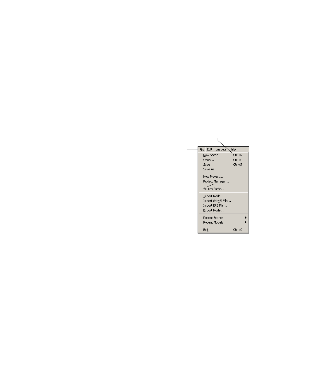
Accessing Commands and Tools
Shortcut keys—Commands that have been mapped to your keyboard. For
example, pressing Ctrl+[key] activates an associated command.
Shortcut keys, if available, are listed to the right of many menu command names
and tooltips. Refer to Online Help for a list of all available keyboard shortcuts.
Note that not every menu command has a shortcut or access key.
Shortcut keys...
...from the keyboard
Press the key that corresponds to a
command. Key combinations are
displayed to the right of their associated
commands in the main menu.
Access keys...
Press Alt+underlined letter of the
menu name to open a menu of
Press a key that corresponds to
...from the menu bar
commands.
...then, from the menu
an underlined letter of a
command name to activate it.
Using Shortcut Keys to Activate Tools
Shortcut keys are mapped to most of the tools used in Avid 3D, and pressing a
key activates a specific tool. Once the key is pressed, the mouse pointer changes
shape to identify the active tool. Any further actions you perform with the
mouse are then related to that tool. For example, pressing the Z key activates
the zoom tool so that holding down the left mouse button zooms in and out of
the scene, and holding down the middle mouse button pans back and forth.
You can move back and forth between different tools quickly by using these
shortcut keys. Only one tool can be active at a time.
55
Page 56

Chapter 3 The Avid 3D Interface
Tools can be activated in one of two modes:
• Sticky—you do not need to hold the key down to keep the tool active.
• Temporary (or supra)—you must keep the key held down for the tool to
remain active.
Sticky-key Mode
You can activate a tool in this mode by quickly pressing and releasing its supra
key. The tool remains active until you choose another tool or press another
supra key to perform a different operation. Pressing a key a second time
deactivates the tool.
Temporary (Supra) Mode
You can activate a tool in temporary, or supra, mode by holding down its key
for longer than a quarter of a second. When you hold down a key and drag the
mouse, the tool is switched off after you release the key. For example, when
you release the O key after holding it down and dragging the mouse, you
deactivate the orbit tool.
Example: Activating Basic Tools
Follow these steps for an example of how to activate and work with the
commonly used camera manipulation tools (pan and zoom, orbit, dolly).
1. Start Avid 3D and load a scene.
2. In a User view, press and hold the letter O key while dragging with the left
mouse button to orbit your scene. When you release the O key, Avid 3D
reverts to the tool you were using before.
3. Quickly press and release the P key. This activates the pan tool in sticky mode.
4. Left-click and drag to pan your scene, hold down the middle mouse button
to zoom in, and hold down the right mouse button to zoom out.
Notice that when you release the mouse button you are still in zoom and
pan mode. This is because the tool was activated as sticky: if you quickly
press and release the key, the tool is activated and remains that way until
you select another tool.
5. To deactivate the pan tool, press the P key again or press Esc.
56
Page 57

6. Quickly press and release the D key. This activates the dolly tool:
- The left mouse button lets you dolly (zoom in and out) at normal speed.
- The middle mouse button lets you dolly slowly.
- The right mouse button lets dolly quickly.
For information on other camera-manipulation tools, see “Navigating in
Viewports” on page 71.
7. To activate another tool, press any key or choose a tool from the control
bar. For example, you can switch to selection mode by pressing the S key
or by clicking the Select button in the control bar.
Keeping Track of the Active Tool
You will often move back and forth between tools as you work. Here are a few
ways to keep track of the tool you are working with:
• There are often visual cues within a viewport to indicate the current tool.
An SRT manipulator appears in the viewport when you are in
transformation mode, object wireframes change color to indicate the
active selection tool, and so on.
Accessing Commands and Tools
• When dragging and dropping items from the library, a status bar appears
in the active viewport and provides information appropriate to the location
of your mouse pointer.
• In most cases, the mouse pointer changes to indicate the active tool. For
example, when the orbit tool is active, the pointer turns into an orbit icon.
• The status bar at the bottom of the interface displays which operation is
mapped to each of the mouse buttons. Always check the status bar for the
current tool status.
Repeating Commands
You can repeat the last command in general, as well as repeat the last
command from a specific menu button. For example, this lets you apply an
operation to the selected object, then select a different object and apply the
same operation again without digging through menus and submenus.
57
Page 58

Chapter 3 The Avid 3D Interface
To repeat the last command:
t Choose Edit > Repeat command name from the menu bar.
The name of the menu item indicates which command will be repeated.
Certain categories of command cannot be repeated:
- Selection commands. This allows you to apply a command to selected
- Interactive manipulation, for example, using the transform tools (V,
- Viewing commands, such as toggling the display of points in a viewport.
- Playback and timeline commands, such as changing frames.
- Camera navigation and viewing commands, such as orbiting,
- Parameter changes made in a property editor.
When the last command can’t be repeated, Edit > Repeat will repeat the
previous command instead.
elements, then select other elements and repeat the command.
C, X) or the Move Point tool (M).
zooming, and framing.
Undoing and Redoing Edits
You can undo most edits made from the Avid 3D interface, such as scaling an
object or deleting a rig.
To undo an edit:
t Choose Edit > Undo from the menu bar, click the Undo button in the
control bar, or press Ctrl+Z.
You can continue to undo actions as far back as the system memory can recall.
Undo does not work on changes in viewport manipulations such as orbit or zoom.
To redo an edit:
t Choose Edit > Redo from the menu bar, click the Redo button in the
control bar, or press Ctrl+Y. You can invoke one redo command for each
undo action.
58
Page 59
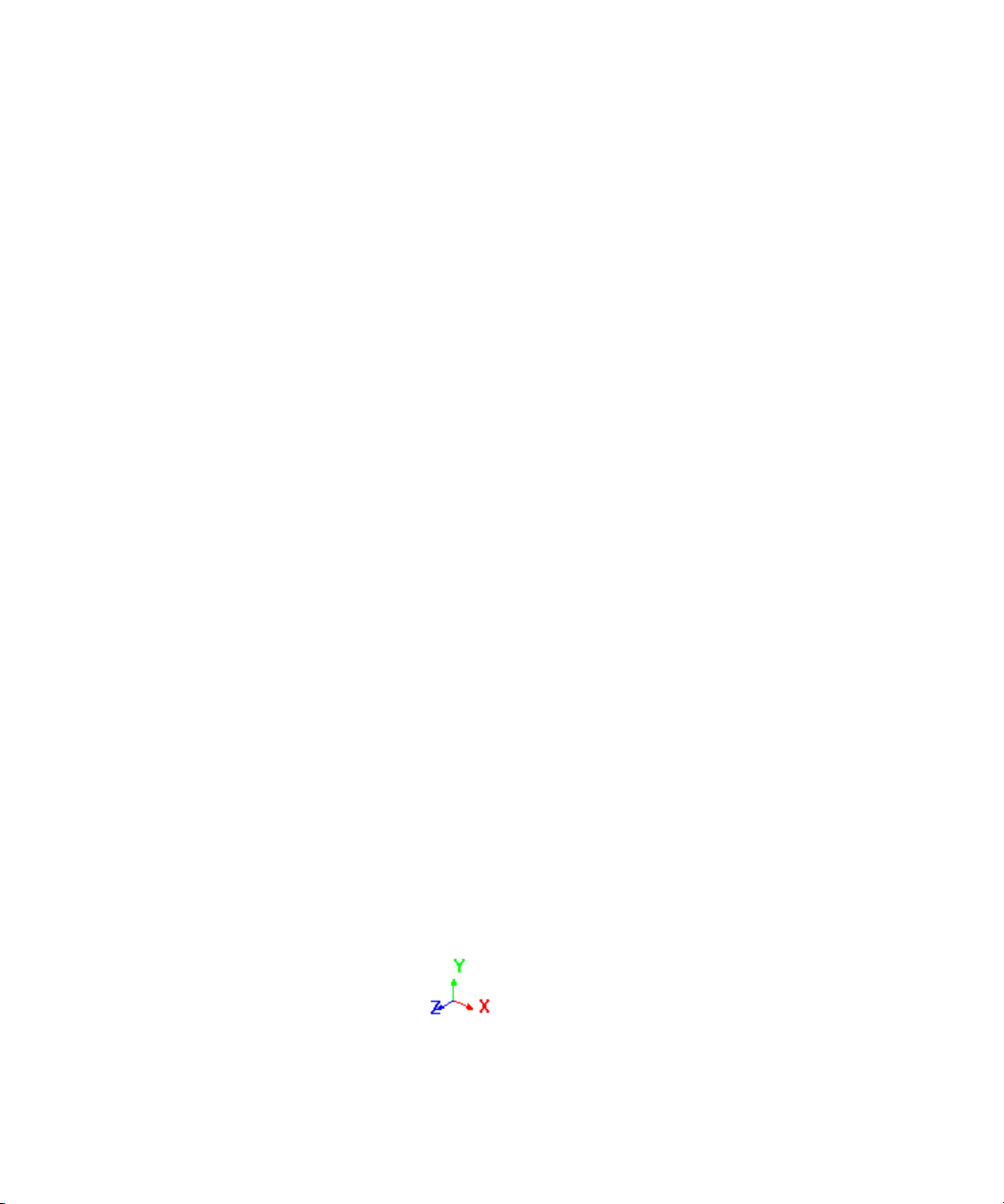
Viewing Your Work in 3D Space
This section provides some background for those who are not familiar with 3D
animation. In particular, it introduces the notion of coordinate systems and
distance units. The four viewports are where you view and manipulate the
scene elements in 3D space.
Coordinate Systems
Coordinate systems allow any point in three-dimensional space to be
represented by a triplet of numbers (X, Y, Z).
Cartesian Coordinates
One essential concept that a first-time user of 3D computer graphics should
understand is the notion of working within a virtual three-dimensional space
using a two-dimensional user interface.
To represent pictorial reality, 3D computer software uses the classical
Euclidean/Cartesian mathematical representation of space. To represent the
geometry of an object, the software uses the Cartesian coordinate system
based on three perpendicular axes, X, Y, and Z, intersecting at one point. This
reference point is called the origin. You can find it by looking at the center of
the grid in any of the 3D windows.
Viewing Your Work in 3D Space
XYZ Axes
To remember the direction of the X, Y, and Z axes, you can use the “righthand” rule: hold up your right hand so that your palm is facing you, then
extend your thumb to the right, hold your index finger up, and point your
middle finger towards you. Your thumb is pointing in positive X, your index
finger in positive Y, and your middle finger in positive Z. The opposite
directions represent negative X, Y, and Z.
59
Page 60

Chapter 3 The Avid 3D Interface
A small icon representing the three axes and their directions is shown in the
corner of each viewport in the camera, geometry, and spotlight views. The
icon’s three axes are represented by color-coded vectors: red for X, green for
Y, and blue for Z.
n
XYZ Coordinates
An easy way to remember the color coding is RGB = XYZ. This mnemonic is
repeated throughout Avid 3D: object centers, visual cues for transformations,
and so on.
With the Cartesian coordinate system, you can locate any point in space using
three coordinates. Positions are measured from a point called the origin, which
is (0, 0, 0). For example, if X = +2, Y = +1, Z = +3, a point would be located
to the right of, above, and in front of the origin.
Location = (2, 1, 3)
Z=3
Y=1
Origin
X=2
XZ, XY, YZ Planes
60
Since you are working with a two-dimensional interface, spatial planes are
used to locate points in three-dimensional space.
The perpendicular axes extend as spatial planes: XZ, XY, and YZ. In the
viewports, these planes correspond to three of the parallel projection windows:
Top, Front, and Right.
Page 61

Viewing Your Work in 3D Space
Imagine that the XZ, XY, and YZ planes are folded together like the top, front,
and right side of a box.
To p
Right
Front
This helps you keep a sense of orientation when you are working within the
parallel projection windows.
Global and Local Coordinate Systems
The location of an object in 3D space is defined by a point called its center.
This location can be described in more than one way or according to more
than one frame of reference.
For example, the global position is expressed in relation to the scene’s origin.
The local position is expressed in terms of the center of the object’s parent.
61
Page 62
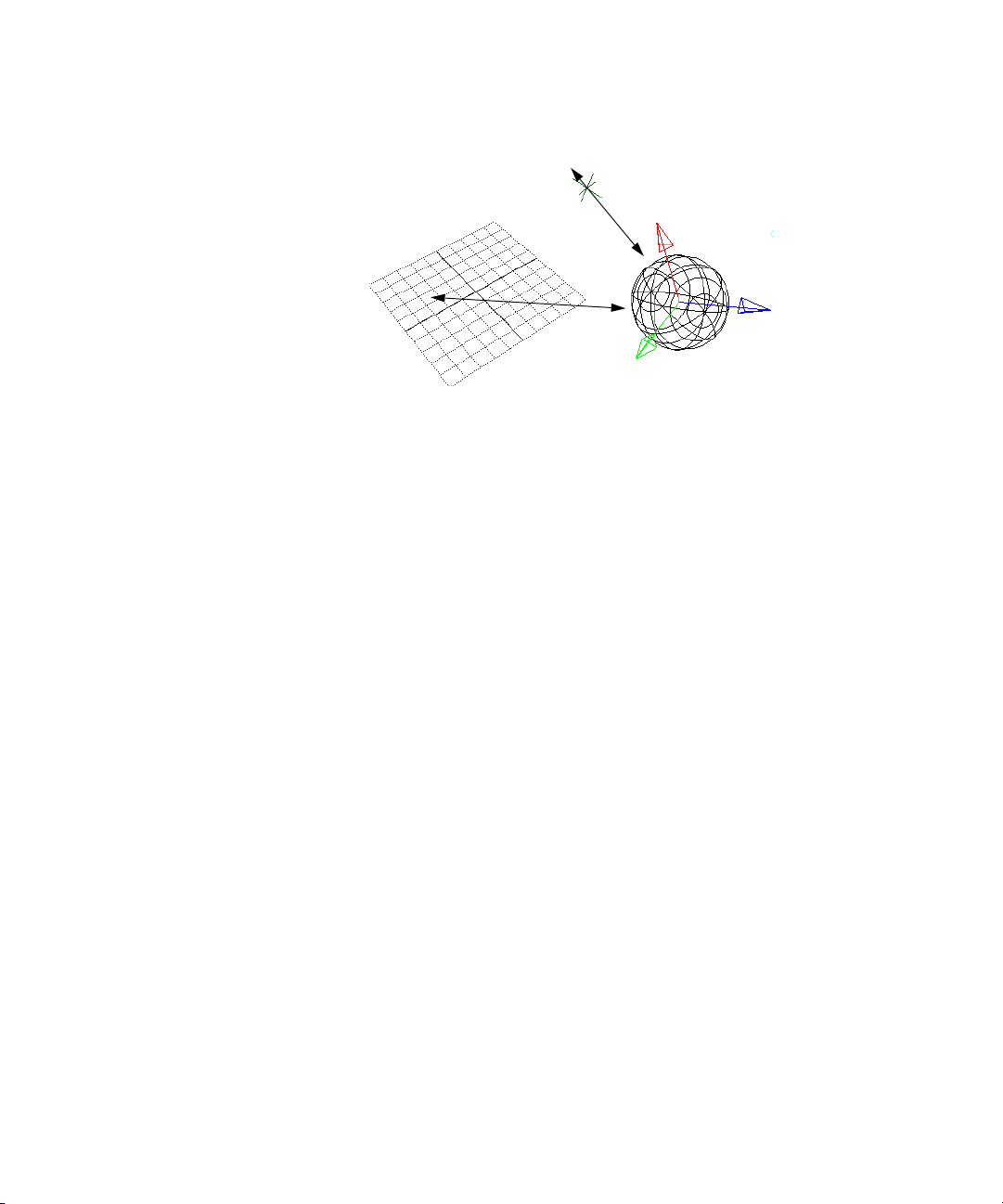
Chapter 3 The Avid 3D Interface
Scene origin
Distance Units
Throughout Avid 3D, lengths are measured in distance units. How big is a
distance unit? It is an arbitrary, relative value that can be anything you want:
one foot, 10 cm, or any other system of measure.
Parent
Object and
its center
Viewports
62
However, it is generally recommended that you avoid making your objects too
big, too small, or too far from the scene origin. This is because rounding errors
can accumulate in mathematical calculations, resulting in imprecisions or even
jittering in object positions.
As a general rule of thumb, an entire rig should not fit within 1 or 2 units, nor
exceed 1000 units.
The viewing area of the interface contains windows, called viewports, where
you can view and work on your scene. Each viewport can display different
types of views. You can display up to four different views in the viewers.
Viewports can have different geometry views (top, front, right, and user) and
display types (shaded, wireframe, texture, hidden line, etc.).
A viewport’s menu bar contains a set of controls that allow you to perform
various functions such as changing views, choosing display types, and resizing
the viewport.
Page 63

Viewing Your Work in 3D Space
Views menu
Provides a variety of
specialized ways in which to
view your scene—see page 66.
Letter Identifier button
Identifies the viewport and,
when selected, alternates
between displaying and hiding
(muting) viewport contents.
Identifying Viewports by Letter
A letter (A, B, C, or D) appears in the upper-left corner of each viewport to
simplify the way in which they are referenced. A refers to the upper-left viewport,
B is the upper-right, C is the lower-left, and D is the lower-right viewport.
Display Types menu Specifies
how visible items in the viewports
are displayed—see page 68.
Resize button
Resizes viewports to fullscreen, horizontal, or vertical
layouts—see page 64.
Muting and Soloing Viewports
When a viewport is muted, it is prevented from displaying its contents. Muting
a viewport’s neighbors helps speed up its refresh rate.
To mute or solo viewports, do one of the following:
t To solo (view just one viewport), left-click on its letter. Left-click a
second time to redisplay all viewports.
t To mute a viewport, middle-click on its letter. Middle-click a second time
to redisplay the viewport.
t Right-click a viewport’s letter to display a menu with mute and
solo commands.
63
Page 64
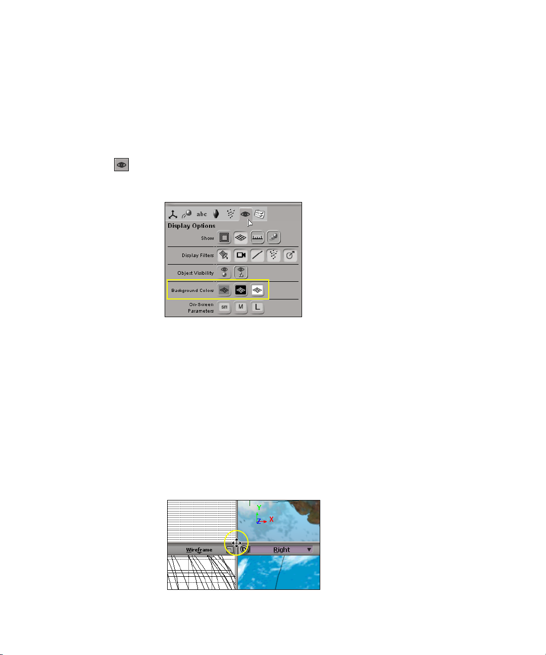
Chapter 3 The Avid 3D Interface
Changing the Viewport Color
By default, a viewport background appears in gray. You can modify it to
display in black or white.
To change the viewport color:
1. Click the Display Options button in the Tools and Options panel.
2. Click the appropriate Background Colors button.
Resizing Viewports
64
There are two ways to resize viewports: interactively set them to any size, or
use the sizing button to set specific sizes.
To resize a viewport interactively:
1. Position the mouse pointer at an intersection of the viewports. You can
either place the pointer where the four viewports meet or where two
viewports meet.
The pointer becomes an arrow indicating in which direction you can
resize the viewports.
Page 65

Viewing Your Work in 3D Space
2. Drag the viewports to whatever size you want. They change size in
relation to each other.
3. To reset the viewports back to equal sizes, middle-click at the viewport
intersection.
Resizing Viewports Using Set Sizes
The sizing button in the upper-right corner of each viewport resizes it so that
the viewport fills the entire screen (full view), a horizontal half-view
(landscape), or vertical half-view (portrait).
You can easily toggle between these views and reduce the viewport to its
original size (quarter-view) at any time.
To toggle between a quarter-view (the four viewports) and full view:
t Click the sizing button.
To toggle between a quarter-view and a landscape view (horizontal):
t Middle-click the sizing button.
To toggle between a quarter-view and a portrait view (vertical):
t Ctrl+middle-click the sizing button.
You cannot toggle directly between the landscape and portrait views.
You can also right-click the sizing button to display a pop-up menu that
includes the following commands:
• Maximize: displays the viewport in full view.
• Horizontal: displays the viewport in landscape view.
• Ver ti ca l: displays the viewport in portrait view.
• Reset Size: displays all viewports in quarter-view.
• Reset All: resets all viewports to their default set of views (i.e., Camera,
Right, Front, Top).
65
Page 66
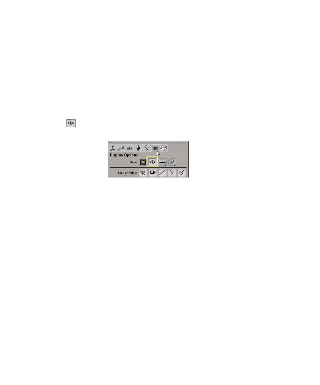
Chapter 3 The Avid 3D Interface
Displaying the Viewport Grid
When you translate objects in the 3D or camera views, the viewport grid
provides a visual frame of reference. In the orthogonal views, translation is
restricted to take place within the plane of the displayed grid. The viewport
grid is not rendered.
To toggle the viewport grid display, do one of the following:
t To toggle the grid in the viewport your mouse pointer is in, press the G key.
t To toggle the grid in all viewports displaying a camera view, click the
Show/Hide Grid button in the Display Options panel.
Viewport Views
Camera Views
n
Viewpoints
66
There are many ways to view and edit your scene in the viewports.
Camera views let you display your scene in a viewport from the point of view
of a particular camera.
Selecting a camera from a viewport’s views menu switches the viewpoint to
that of a “real” camera in your scene. All other views such as User, Top, Front,
and Right are not associated to an actual camera.
You can also choose to display the viewpoint of any spotlight in the scene.
Viewpoints show you the geometry of objects in a scene. You can also choose
different display types to change the visual appearance of the objects seen in
viewpoints (see “Display Types” on page 68).
Page 67
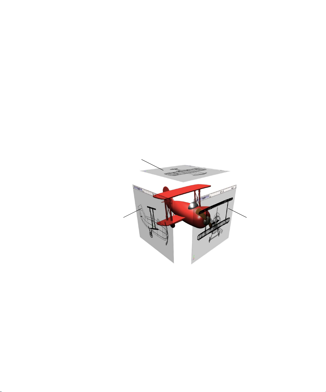
Viewing Your Work in 3D Space
Top, Front, and Right Views
The top, front, and right views are parallel projection views, called such
because the object’s projection lines do not converge in these views. Because
of this, the distance between an object and the camera has no influence on the
scale of the object. If one object is close to the camera, and an identical object
is farther away, both appear to be the same size.
The top, front, and right views are orthographic, which orients the camera so it
is perpendicular (orthogonal) to specific planes:
• The top view faces the XZ plane.
• The front view faces the XY plane.
• The right view faces the YZ plane.
To p
Front Right
User
The user view is a user-defined viewpoint that shows objects in a scene from a
virtual camera’s point of view. This view can be either perspective or
orthographic.
• In the perspective view, objects appear to converge toward a central
vanishing point, and objects closer to the camera appear larger than those
farther away.
• In the orthographic view, objects remain in parallel projection with the
view being perpendicular (orthogonal) to the XY plane in camera space.
67
Page 68

Chapter 3 The Avid 3D Interface
The user point of view can be placed at any position and at any angle within the
global 3D coordinate system. You can orbit, dolly, zoom, and pan in this view.
Spotlight
Spotlight views let you select from a list of spotlights available in the scene.
Selecting a spotlight from this list switches the point of view in the active
viewport relative to the chosen spotlight. The point of view is set according to
the direction of the light cone defined for the chosen spotlight.
Display Types
There are several different ways in which you can display objects in a
viewport. By default, all objects are displayed in wireframe mode. Some
display types provide less detail but are less computationally intensive than
others—and this speeds up your screen refresh.
To set the display type for a specific viewport:
68
Click the Display
Type menu to
choose a display
type from its menu.
Page 69

Outputting Avid 3D Views to an Avid Mojo
Here are some examples of several of the available display types. For more
information on each display type, refer to the Online Help (Help > Avid 3D
Help) for the Viewport topic.
Wireframe
Shaded
Hidden Line Constant (flat-shaded)
Te xt u re d
OpenGL
Outputting Avid 3D Views to an Avid Mojo
Avid Mojo™ is a portable Digital Nonlinear Accelerator that allows you to
output hardware and software rendered effects from Avid 3D to a monitor in
real-time.
When you have an Avid Mojo connected to your Avid 3D workstation, you
can output content from Avid 3D to a monitor using the Mojo to accelerate the
display of effects. You can choose a view to output from the Mojo Options tab
in the tools and display panel.
n
You can also output to the Mojo from the flipbook and after rendering—see
“Loading Animation in the Flipbook” on page 334 and “Rendering Your
Scene” on page 383.
69
Page 70

Chapter 3 The Avid 3D Interface
To output Avid 3D views to a monitor:
1. Click the Options button in the tools and options panel, then click the
Mojo Options button in the toolbar that appears to open the Time
property editor.
2. Choose the Monitor Type to which you’re outputting content. This can
be either NTSC or PAL.
3. Choose an Avid 3D view to output via the Mojo by setting the View
Output to one of the following:
- Disabled: nothing is output to the monitor.
- 3D View A: the display in viewport A is output to the monitor.
- 3D View B: the display in viewport B is output to the monitor.
- 3D View C: the display in viewport C is output to the monitor.
- 3D View D: the display in viewport D is output to the monitor.
- 3D Auto A/B/C/D: the viewport that has focus is output to the
- Render View: outputs the rendered image from the render preview
monitor. Click a viewport to give it focus.
or, the render view when rendering an image to disk.
The image/frame is not displayed on the monitor until the last tile
is rendered.
-The FX View option is not implemented in Avid 3D.
- Image Clip View: the image clip view, as seen in the Texture Clip
Viewer, is output to the monitor.
Configuring Avid 3D to Output to an Avid Mojo
The following procedure explains how you can configure Avid 3D to output
to a Mojo.
n
70
If you have installed other Avid products you may already have a Mojo driver
installed. You must ensure that the most recent driver has been installed.
The driver files for Mojo are called Flamethrower.inf and Flamethrower.sys.
They are located in the
Application\bin
subdirectory of the installation path.
Page 71

Navigating in Viewports
To update your Mojo driver:
1. Close all running sessions of Avid 3D.
2. From the Windows task bar, choose Start > Control Panel > System.
3. On the Hardware tab, click the Device Manager button. In the device
manager, expand the Sound, video & game controllers node.
4. Double-click Avid Technology Mojo to open its Properties dialog box
and switch to the Driver tab.
5. Click the Update Driver button.
6. From the Hardware Update Wizard, choose Install from a list or specific
location and click Next.
7. Choose Don’t Search. I will choose the driver to install. Then click
Next and choose the latest driver.
If no drivers are listed, click Have Disk. Then Browse to the
Application\bin subdirectory of the installation path, choose
Flamethrower.inf, and click OK.
When you first launch Avid 3D with Mojo support, it may request that you
update your firmware. Simply follow the instructions to perform the update.
Once the firmware is updated, you’ll need to power the Mojo off and on again
and restart Avid 3D for the changes to take effect.
n
If Avid 3D is installed on the same machine as other applications that support
Mojo output (such as Avid XpressPro), make sure that those programs use the
same version of the Mojo driver and firmware as Avid 3D. Programs requiring
different versions of the Mojo driver cannot co-exist peacefully on the same
machine.
Navigating in Viewports
A set of viewport navigation controls in the control bar and their
corresponding shortcut keys let you change the way in which you view your
scene. You can use these controls and keys to zoom in to and out of a scene,
frame objects within a viewport, and orbit, track, and dolly the scene.
Camera buttons in the control bar
71
Page 72

Chapter 3 The Avid 3D Interface
Framing Objects in Viewports
Framing commands let you instantly zoom in to or out from selected objects in
viewport geometry views. You can frame objects in two ways: framing
selected objects or framing all visible objects in one or all viewports.
To frame all visible objects in a viewport:
t Position the mouse pointer over the viewport and press A.
To frame all visible objects in all viewports:
t Press Shift+A or click the Frame All Objects In All Viewports button on
the control bar.
To frame all selected objects in a viewport:
t Position the mouse pointer over the viewport and press F.
To frame all selected objects in all viewports:
t Press Shift+F or click the Frame Selected Object In All Viewports
button on the control bar.
Changing the Viewpoint
You can zoom in to and out of your scene or pan in all 3D views using the
zoom controls.
Panning and Zooming
To pan and zoom using the camera pan tool:
Click the Camera Pan Tool button on the control bar, or press the P supra key.
Then do any of the following:
t Press the left mouse button and drag to pan.
t Press the middle button to zoom in.
t Press the right button to zoom out.
t Click the Camera Pan Tool button or press P again to deactivate pan
and zoom mode.
72
Page 73

Navigating in Viewports
To pan and zoom using the camera zoom tool:
Choose the Camera Zoom Tool button on the control bar, or press the Z supra
key. Then do any of the following:
t Press the left mouse button and drag to zoom in or out.
t Press the middle button and drag to pan.
t Click the Camera Zoom Tool button or press Z again to deactivate
zoom mode.
By default, Avid 3D zooms into or out from the center of the view.
n
Orbiting
Dollying and Rolling
Zooming in or out changes the view angle setting of the camera, the same as
when you zoom with a real camera. Use the dolly tool if you don’t want to
change the view angle.
Orbiting is only possible in the perspective views. Orbiting rotates a camera,
spotlight, or user viewpoint around its point of interest. This lets you study
your scene’s overall “look” in any angle in any view.
To orbit:
t Click the Camera Orbit Tool button on the control bar, or press the O
supra key while in User view.
You can dolly toward the camera interest in a perspective view or toward the
center of the viewport in an orthogonal view. Rolling is only possible in the
perspective views.
To dolly:
Click the Camera Dolly Tool button on the control bar, or press the D supra
key. Then do any of the following:
t Press the left mouse button and drag to dolly.
t Press the middle button to dolly slowly.
t Press the right button to dolly quickly.
73
Page 74
Chapter 3 The Avid 3D Interface
t Click the Camera Dolly Tool button or press D again to deactivate
To roll the camera about its Z axis:
Click the Camera Roll Tool button on the control panel or press the L supra
key, then do any of the following:
t Press the left mouse button and drag to roll.
t Press the middle button to roll slowly.
t Press the right button to roll quickly.
t Click the Camera Roll Tool button or press L again to deactivate
Resetting Coordinates
You can reset the camera and other viewport views so that their global point of
origin (X = 0, Y = 0, Z = 0) is in the center of the viewport.
To reset the camera and view coordinates:
dolly mode.
roll mode.
t Click the Reset Camera button on the control bar, or position the mouse
pointer over the viewport and press the R key.
Hiding and Unhiding Objects
You can quickly hide and unhide selected objects in the viewports using the
Display Options panel or the H shortcut key. This is a quick way to set the
viewport visibility of a selected element.
n
74
Hiding objects eliminates their visibility both in the viewports and in the
rendered output.
To hide and redisplay selected objects in the viewports:
1. Do one of the following:
t In any viewport, select the object you want to temporarily hide,
and press H.
Page 75
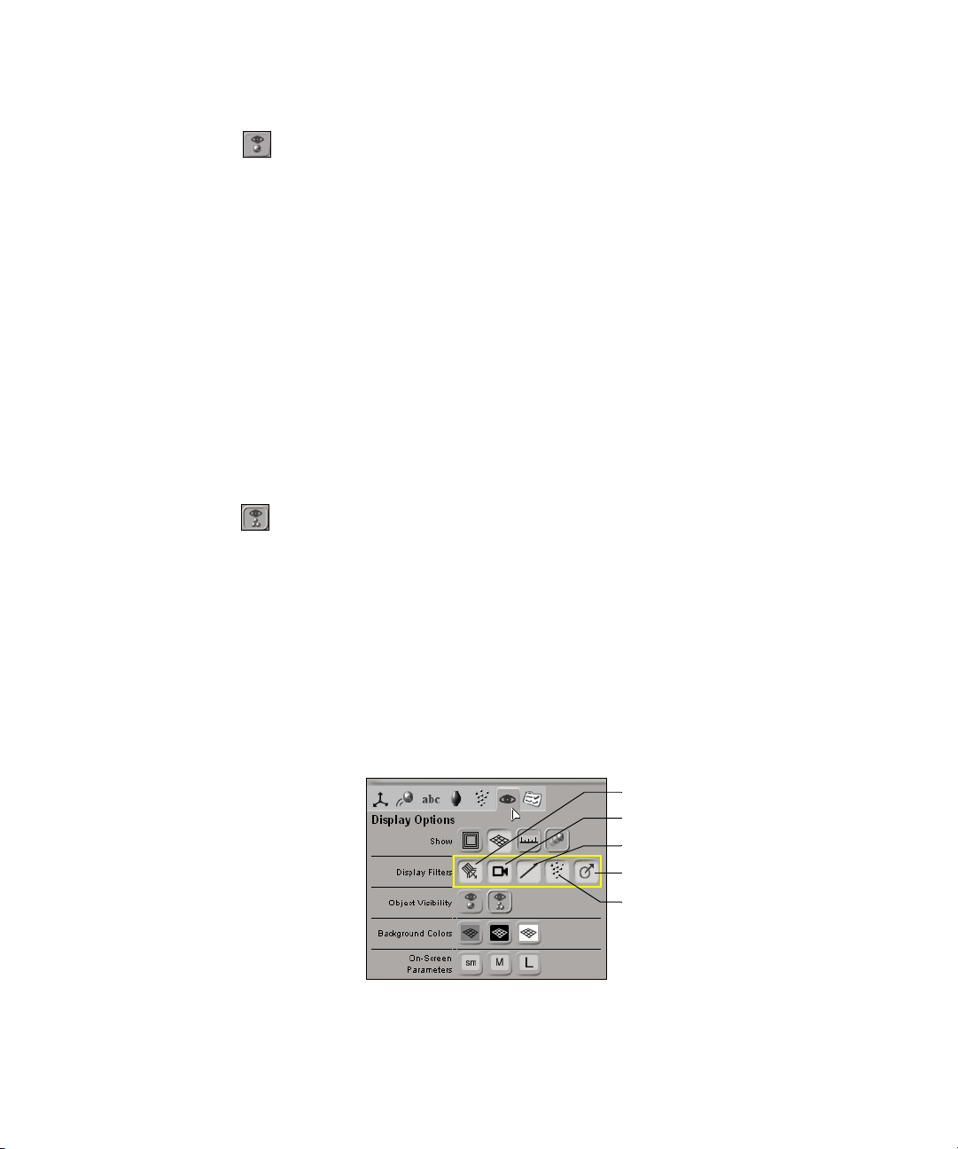
Display Filters
Hiding and Unhiding Objects
t From the Display Options panel, click the Show/Hide Selected
Objects button.
The selected object is hidden in all geometric views but remains
visible in the explorer (an H will appear on the icon of the hidden
node). Hidden elements are not rendered in the render region nor do
they appear in the final output.
2. Pressing H or clicking the Show/Hide Selected Objects button again
redisplays the hidden object.
If you selected another element or modified the scene after you hid the
object, pressing H or choosing View > Hide/Unhide Selection again has
no effect on the hidden element. In this situation, the hidden object can
only be redisplayed by selecting its node in the explorer and pressing H or
clicking the Toggle Visibility of Selected Objects button again.
To unhide all hidden objects in the viewports:
t From the Display Options panel, click the Show All Objects button.
In addition to hiding or displaying individual objects, you can use display
filters to hide or display different types of scene elements, such as lights,
cameras, curves, control objects, and particles.
To display or hide different types of elements in the viewport:
t Toggle the various Display Filter buttons in the Display Options panel.
Lights
Cameras
Curves and Motion Paths
Control Objects and Rig Handles
Particles
75
Page 76

Chapter 3 The Avid 3D Interface
The Library Panel
The library panel is found on the right side of the Avid 3D interface. It is
divided into tabs that contain libraries of objects, rigs, clips, particles, and
other elements that can be used as building blocks for Avid 3D scenes.
Elements such as objects, models, and rigs can be added to a scene simply by
dragging an element’s thumbnail into a viewport. Elements such as materials,
textures, still images, and video clips are added to an object by dragging their
thumbnails onto an object in the viewport.
For more information about using the elements in the library panel, see “Using
the Library Panel” on page 98.
Sample Projects library
Scene explorer—see
next section on page 76.
The Scene Explorer
The explorer displays the contents of your scene as a list of nodes that expand
from the top root. You normally use the explorer as an adjunct while working
in Avid 3D to find or select elements. For example, the scene explorer is a
useful tool to help you select hidden elements in a scene. You can also rename
elements using the scene explorer.
Object library Model library
Digimation
Model Bank
Material and
Fx library
Still Images library
Video library
Video library
76
To see properties of those selected scene elements, use the multi-purpose
editor, as described in “The Multi-Purpose Editor” on page 79.
Page 77

To open the scene explorer:
t In the library panel, click the Scene Explorer tab.
The Scene Explorer
n
If the panel is too short and a scroll bar appears on the side, you can see the
rest of the contents by either scrolling with the scroll bar or panning by
clicking and dragging up and down in an empty area.
Click the Scene Explorer
tab in the library panel to
open the scene explorer.
Click an item to display
those types of elements in
the tree panel below.
Click an item to select it.
Selected items are highlighted.
Rename the selected item by
pressing F2 and entering a
new name.
Selecting Scene Elements in the Scene Explorer
Selecting elements in the explorer is quite straightforward. In particular, you
can select any element, even if it is unselectable or hidden in the 3D views.
• To select a scene element, simply click on its name in the explorer.
Ctrl+click to multi-select individual nodes.
• To select a range of elements, click on the first element’s name in the
range, then Shift+click on the last element’s name in the range. These two
elements, plus all the elements between them, become selected.
Renaming Scene Elements
You can rename elements in your scene using the explorer. You can rename
lights, cameras, and geometric objects.
77
Page 78

Chapter 3 The Avid 3D Interface
To rename scene elements:
t Select the element you want to rename in the scene explorer and press F2.
Then type a new name for the element.
The Tools and Options Panel
The Tools and Options panel is where you can access many tools used for
different tasks in a scene, such as transforming elements, animating, or
deforming objects. As well, you can access a number of options to set up your
scene, such as for the display in the viewports or output options to determine
how to render your scene.
Animation
Transform tools
tools
Text tools
Deformation
tools
Particle
tools
Options
Display options
• Transform Tools panel: Contains tools that let you translate, rotate, and
scale objects in your scene. It also includes a number of mode buttons that
let you specify how objects are transformed.
For more information, see “Transforming Objects” on page 117.
• Animation Tools panel: Contains tools that let you animate objects in
different ways, such as by setting keyframes, putting objects on paths,
constraining them, or using math presets.
For more information, see Chapter 10 “Animating in Avid 3D” on page 261.
78
• Text Tools pane l : Contains tools that let you create and edit text.
For more information, see Chapter 7 “Working with Text and Logos” on
page 173.
Page 79

• Deformation Tools panel: Contains tools that let you deform objects in
many different ways.
For more information, see Chapter 6 “Modifying Object Geometry” on
page 139.
• Particle Tools panel: Contains tools that let you create and apply
particles, forces, and obstacles in your scene.
For more information, see Chapter 11 “Particles” on page 341.
• Display Options panel: Contains tools that let you determine what’s
displayed or hidden in the viewport.
For more information, see “Hiding and Unhiding Objects” on page 74 and
“Viewports” on page 62.
• Options panel: Contains tools that let you set up preferences for different
aspects of working in Avid 3D, from rendering and time properties to data
management and the function curve editor.
For more information on each option, see the Online Help.
The Multi-Purpose Editor
The Multi-Purpose Editor
The multi-purpose editor lets you edit properties of any type of scene element.
You can also open the profile and function curve editors from here. The multipurpose editor appears as a floating window. You can resize the window by
dragging its borders, and move it around the interface by clicking and
dragging on its title bar.
To open the multi-purpose editor:
1. Select an element in a 3D view or in the scene explorer.
2. Click the Multi-Purpose Editor button on the control bar.
3. Click the tab that corresponds to the properties you want to edit (or editor
that you want to use).
4. Click a node in the tree panel on the left, and its property editor appears in
the panel on the right.
See “Modifying Properties in Property Editors” on page 80 for information in
general about editing properties.
79
Page 80

Chapter 3 The Avid 3D Interface
Material and Fx
properties
Geometry and
Deform properties
Click element name
in the tree to open its
property editor in the
panel on the right.
Texture clip
viewer
Profile
editor
Function curve
editor
The following is a summary of the properties and editors available in the
multi-purpose editor.
• Geometry and Deform properties—see “Basic Scene Elements” on
page 100 and “Deforming Objects” on page 140.
• Material and Fx properties—see “Materials” on page 238, “Textures”
on page 245, as well as “Attaching Sprites and Images to Particles” on
page 374 for using sprites with particles.
• Texture clip viewer—see “Textures” on page 245.
• Profile editor—see “Working with Profiles” on page 162.
• Function curve editor—see “Editing Function Curves” on page 285.
Modifying Properties in Property Editors
Property editors are found throughout Avid 3D—for instance, you can access
property editors from some buttons in the tools and options panel, where they
are used to view and change project, scene, and render settings. However, you
will most likely use property editors to define and modify a scene’s various
elements. You can find elements’ property editors in the multi-purpose editor.
n
80
You can also modify an object’s properties using the on-screen parameters—see
“Modifying On-screen Parameters” on page 88 for more information.
Page 81
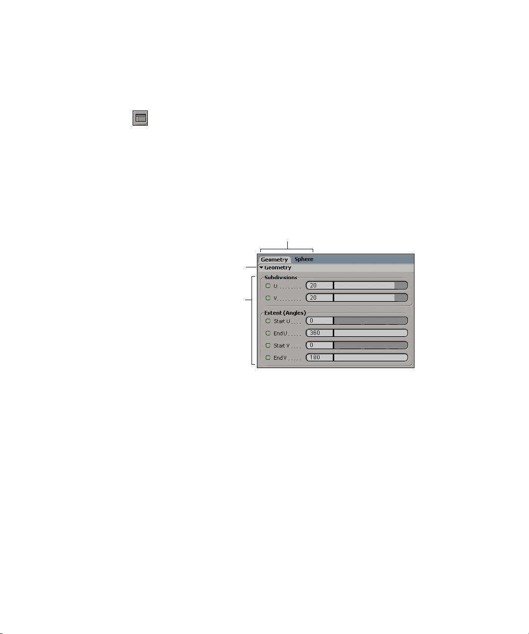
To open an element’s property editor:
P
1. Select the element in a 3D view or in the scene explorer.
2. Open the multi-purpose button by clicking the Multi-Purpose Editor
button in the control bar.
See the previous section, “The Multi-Purpose Editor”, for information in
general about the multi-purpose editor.
Anatomy of a Property Editor
Parameter Set headers
Click the arrow to expand and
collapse the property set.
Property-page controls
For viewing and setting
parameter values for sets
of grouped properties.
Modifying Properties in Property Editors
roperty Page tabs
Switch between sets of grouped
parameters within a property set.
81
Page 82

Chapter 3 The Avid 3D Interface
Property Page Controls
Color box
Opens color editors from which
you can pick or define the colors
you want to use. See “Defining
Color Properties” on page 92 for
Let you enter values for the
parameters. See “Entering
page 83 for more information.
Shows status of animatable
parameters (whether or not the
parameter is animated). You can also
set and remove keys by clicking this
button. See “Keyframe Animation” on
page 277 for more information.
more information.
Values in a Text Box” on
Animation button
n
Not all of the options described above are available in every property editor.
Changing Values Using Sliders
To change values using sliders, do one of the following:
Sliders
Let you change values by
dragging the bar or arrow
in the slider. “Changing
Values Using Sliders” on
page 82 for more
information.Text boxes
Check box
Toggles the option so that
it’s active or inactive. A
check mark appears in
the box when it’s active.
Drop-down lists
Let you select one option
from several. Click the
arrow beside the list to
open its menu.
82
t Drag a slider to the right to raise the value or to the left to lower the value
in the text box.
t Drag a slider to the right or left while pressing the Shift key to make
finer adjustments.
t Drag a slider to the right or left while pressing the Ctrl key to change the
value of all the sliders in a color-control group simultaneously.
t Drag with the middle mouse button to have the scene update only when
you release the mouse button instead of refreshing continuously as you
drag. This is especially useful when setting values on parameters that may
take a long time to update.
Page 83

When you resize a property editor so that there is not enough room to display
or use a slider effectively, the slider becomes an input box. When you enlarge
the property editor, the input box becomes a slider again.
Entering Values in a Text Box
There are many ways to enter information in a text box. You can enter
information the conventional way by using your keyboard. For numeric input,
you can also use gestural movements and key combinations to increase or
decrease the parameter values.
Modifying Properties in Property Editors
Sliders become input
boxes at small sizes.
Sliders at larger sizes.
n
To move from one text box to the next one in the same property editor, press the
Tab key. To move back to the previous text box, press Shift+Tab.
To enter information by typing:
Move the mouse pointer inside the text box and click. The pointer shape
becomes a text cursor (flashing vertical bar). Any existing text is selected and
is overwritten as soon as you begin typing.
If you click in the text box a second time, the text is deselected and the cursor
is placed where you clicked. You can now:
• Use the left- and right-arrow keys on the keyboard to move the cursor to
the appropriate place in the text box.
• Drag the cursor over the part of the contents you want to replace. The
selected characters are highlighted. Now type in the text you want.
• Press Shift+left- or right-arrow key to select characters that are to the left
or right of the cursor. You can delete or replace these characters.
• Double-click to select a word or value so that you can replace it
completely with the text that you type.
• Right-click to open a pop-up menu and choose the command to Undo,
Cut, Copy, Paste, Delete, or Select All the contents of the text box.
83
Page 84

Chapter 3 The Avid 3D Interface
• Delete characters to the left of the cursor using the Backspace key, or
delete characters to the right of the cursor using the Delete key.
• To cancel text box input, press the Esc key.
n
If you have problems entering decimal values, open the Windows Control Panel
and make sure that the Regional Settings are set to English (United States).
To enter information by gestural input (scrubbing):
t Click and drag the mouse pointer in a circular motion over a text box that
supports numeric values. This is known as scrubbing. To increase the
value, scrub in a clockwise direction; to decrease the value, scrub in a
counterclockwise direction.
- Press the Shift key while scrubbing to increment or decrement values
by a factor of 0.1.
- Press the Ctrl key while scrubbing to increment or decrement values
by a factor of 10.
To enter information by increments, do one of the following:
t Click in the numeric text field and press the square bracket keys ([) and (])
to increment and decrement values as follows:
Press this... To do this...
] Increment by 1
[ Decrement by 1
84
Ctrl+] Increment by 10
Ctrl+[ Decrement by 10
Shift+] Increment by 0.1
Shift+[ Decrement by 0.1
Page 85

Modifying Properties in Property Editors
t Click in the numeric text field and press the arrow keys to increment or
decrement values as follows:
Press this... To do this...
Ctrl+right-arrow Increment by 10
Ctrl+left-arrow Decrement by 10
Shift+Ctrl+right-arrow Increment by 0.1
Shift+Ctrl+left-arrow Decrement by 0.1
n
Relative Input Using Math Operations
If you have a mouse wheel, click in the numeric text field, then roll the wheel
forward to increment the value or backward to decrement the value.
All text boxes allow you to input relative values by means of four basic math
operations (addition, subtraction, multiplication, and division), as well as other
operators such as linear and random.
To input relative values:
1. Click in a text box to select the value it contains.
2. Enter the number to add, subtract, divide, or multiply.
3. Enter the symbol for the math operator ( + – * / ). You can use only one
math operator per text box.
4. Press Enter.
For example, if the selected value in the text box is 10 and you replace this
value by 5+ and press Enter, the result is 15 because you added 5 to the
existing value.
When you have multiple elements of similar parameter values, anything you
enter in a text box is applied to all these parameters:
85
Page 86

Chapter 3 The Avid 3D Interface
Operator Results
value
value+
value-
value*
value/
l or L(min, max)
r or R
r(x) or r(-x)
Sets all selected element properties to that value. For example,
entering an X-axis rotation value of 5 sets all selected objects’
rotational values to 5. This is also known as absolute input (see
the following illustration).
Increments all the selected elements by that value. For example,
entering 2+ in an X-axis translation parameter shifts all selected
objects by 2 distance units. Math operations are known as
relative input.
Decrements all the selected elements by that value.
Multiplies all the selected elements by that value.
Divides all the selected elements by that value.
Creates a linear range through the selection, according to the
original selection order. For example, L(4,8) when applied to the
X-axis translation parameter of a group of three cubes causes
each object to move 4, 6, and 8 distance units along the X axis,
respectively.
Creates a random value for each selected element, between 0 and 1.
Creates a random value for each selected element between 0 and
the value for (x). If r is followed by (–x), a random value between
0 and the negative value is inserted.
86
r(min, max)
Creates a random value for each selected element within the
specified range.
g(mean, var)
Creates a random value following a normal distribution among
the selected elements.
The following illustrations describe the different ways in which elements can
be transformed using text box input. For illustrative purposes, the example of
translation is used, but the concepts apply to any parameter:
Page 87

Absolute Input
Entering a numeric value in an XYZ text box
repositions all selected objects to the specified
position on their X,Y, or Z axes.
This example: Translation: Y = 3
(spheres all repositioned to 3 on the Y axis)
Relative Input
Entering (value)+ or (value)– in an XYZ text
box increases/decreases the relative value of
each selected object. You can also enter
(value)* and (value)/ to multiply and divide the
relative value.
This example: Translation: Y = 3+
(Y value of each selected sphere increased by
three distance units)
Random Input
Entering a value of R(min,max) in an XYZ text
box randomly repositions each selected object
anywhere between the specified minimum and
maximum values.
Modifying Properties in Property Editors
This example: Translation: Y = R(0,6)
(spheres randomly repositioned between 0
and 6 on the Y axis)
Linear Range
Entering a value of L(min,max) in an XYZ text
box repositions each selected object on a
linear path between the specified minimum
and maximum values. The first selected object
receives the minimum value and last selected
object receives the maximum value.
This example: Translation: Y = L(0,6)
(spheres repositioned equally on a linear
range between 0 and 6 on the Y axis)
87
Page 88

Chapter 3 The Avid 3D Interface
Modifying On-screen Parameters
In addition to marking, editing, and animating parameter values in a property
editor, you can display parameters directly in viewport B and do all these tasks
on screen.
On-screen parameters are displayed for the selected object on a semitransparent menu in the upper-right corner of viewport B. For most objects,
only their Transform parameters appear on-screen; however other objects,
especially rigs, also have other parameters that can be displayed on-screen.
Displaying On-screen Parameters
To display on-screen parameters in viewport B:
1. Select an object, and its on-screen parameters appear in the upper-right
corner of viewport B.
If you multi-select objects, only the parameters for the first object you
selected are displayed on-screen.
88
On-screen parameters are
displayed for the selected rig
in a semi-transparent menu
in viewport B.
Page 89
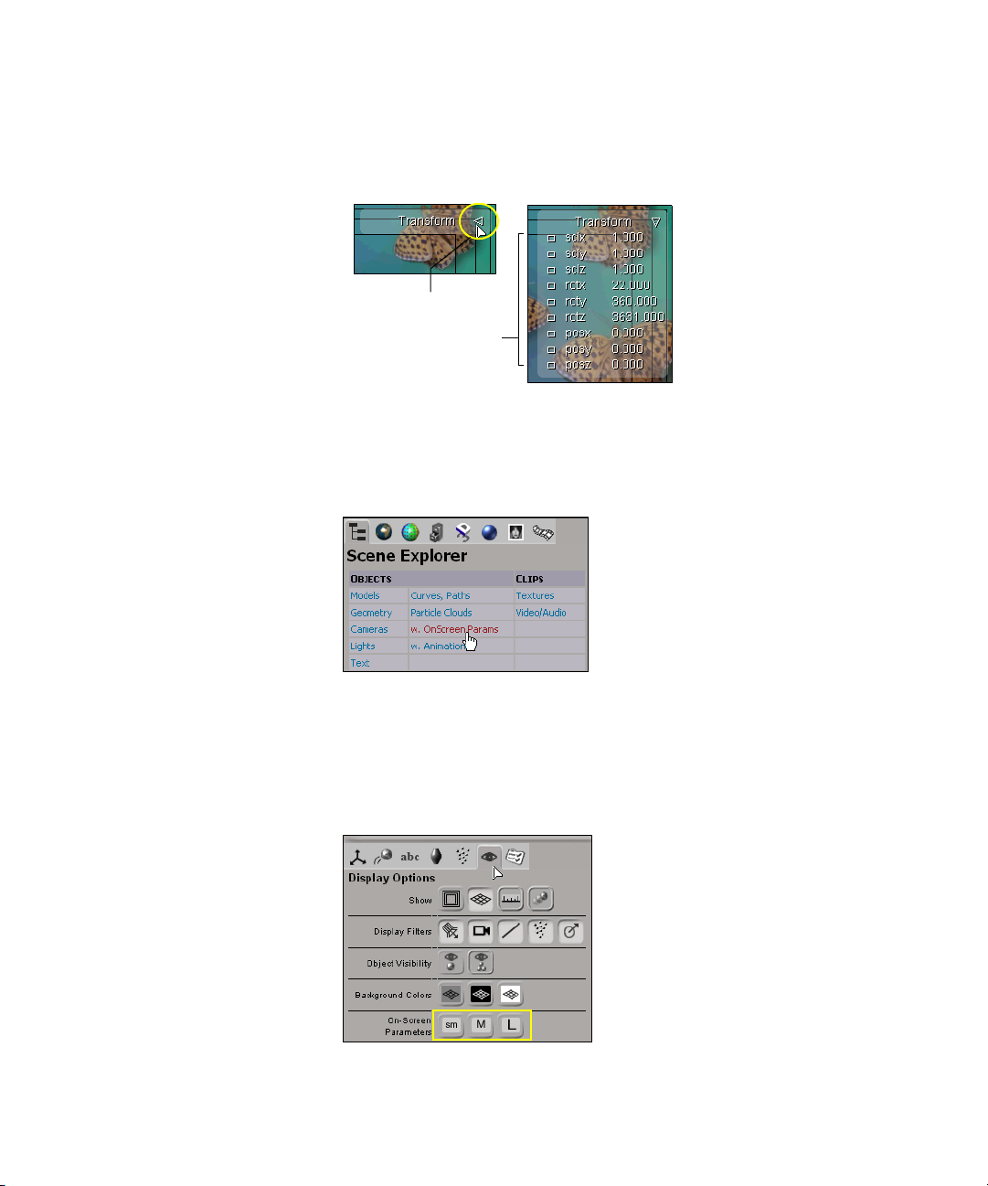
Modifying On-screen Parameters
2. Click the arrow beside the parameter set name (in this case, Transform) to
open up the menu of parameters available for that set.
Click arrow beside
parameter set name
to open menu that
displays the set’s
parameters.
Some objects have on-screen parameters other than the Transform
parameters. You can find out which objects these are by clicking the
Scene Explorer tab in the library panel and selecting Objects >
w. On-screen Params.
To set the size of the font for on-screen parameters:
1. Click the Display Options tab in the tools and options panel.
2. Select a font size from the On-screen Parameter buttons: small (sm),
medium (M), or large (L).
89
Page 90
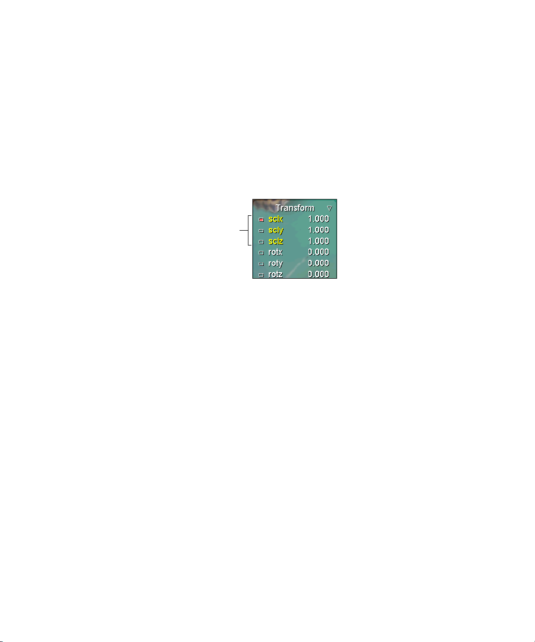
Chapter 3 The Avid 3D Interface
Modifying and Animating the On-screen Parameter Values
You can easily modify the on-screen parameters, as well as animate them. Before
you modify or key parameter values, you should mark them. Marking parameters
lets Avid 3D know that you want to modify or key only those parameters.
All marked parameters’ values are modified when you drag the mouse or are
keyed when you click the keyframe button in the animation controls. For
general information on setting keys, see “Setting Keys” on page 278.
Marked parameters
are displayed in yellow.
To mark parameters, do one of the following:
t Click the parameter name: it turns yellow to indicate that it’s marked.
90
t Press Shift+click to mark multiple parameters.
t Press Ctrl+click to toggle the marked state of the parameters.
To edit parameter values:
Click and drag on a parameter name or its value to modify the value:
• Drag to the left to decrease the value, and drag to the right to increase it.
• Press Ctrl while you drag for coarse control.
• Press Shift while you drag for fine control.
• Press Ctrl+Shift while you drag for very precise control.
• Press Alt while you drag to extend beyond the range of the parameter’s
slider in its property editor (if the slider range is smaller than its total range).
Page 91
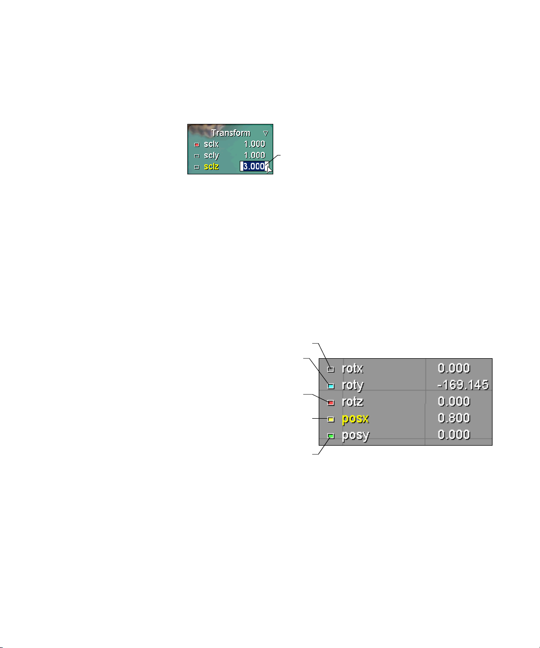
Modifying On-screen Parameters
• Double-click on a numeric value to edit it using the keyboard. The current
value is highlighted, so you can type in a new value. Only the parameter
you click on is affected even if multiple parameters are marked.
Double-click the value,
then type in a new one.
To animate parameter values, do one of the following:
t Click on the parameter’s animation button to set or remove a key for the
corresponding parameter.
t Right-click on an animation button to open the animation menu for the
corresponding parameter. From this menu, you can set or remove keys,
copy and paste keys between parameters, or move between keys. See
“Keyframe Animation” on page 277 for more information.
The color of the animation box beside the parameter indicates the following
information:
Empty: the parameter is not animated.
Blue: the parameter is animated by
something other than keys (such as a
math preset).
Red: the parameter has a key at the
current frame.
Yellow: the parameter is animated and
the value has been modified but is not
yet keyed.
Green: the parameter is animated and
the current value is the interpolation
between keys.
91
Page 92

Chapter 3 The Avid 3D Interface
Defining Color Properties
There are a number of standard ways of defining color properties, for textures,
materials, and lighting.
Defining Colors with Sliders
To define a color using the color sliders:
1. Select the color model that best suits your needs. Below the color box, you
can click on the color model button to toggle between RGB, HLS, and HSV.
2. Do one of the following to set the color:
t Click and drag the sliders to change the strength of each channel
independently, or type a numerical value directly in the text box
beside the sliders.
92
n
Color box
t To move all three sliders at once, hold the Ctrl key down while
dragging the color sliders.
t For fine-tuning a single color value, hold down the Shift key while
dragging the color sliders.
You can quickly copy a color by clicking a color box and dragging and
dropping its “color chip” to another color box in the same property page or
another one. This is especially useful when you want to match ambient or
diffuse colors among objects.
As you use the color sliders, you will notice that each slider immediately
updates to show you a gradient of the color you have selected. The slider
shows you what color will result if you move the slider to a new position.
The specific channel corresponding to a slider depends on the color channel
you selected; for example, if you selected RGB, the sliders correspond to the
red, green, and blue channels. The values range between 0 and 1.
Color
model
Color sliders
Page 93

Defining Color Properties
n
When you are defining materials, you can type values greater than 1 to
compensate for transparency and reflectivity.
Defining Colors with the Color Editors
When defining or choosing colors, or to choose one from a viewport, you can
use one of the two color editors. In the full color editor, you can create and
modify colors for your materials and lights. This can be useful for creating
specific palettes to apply consistently to a group of materials. You can also use
the color picker to pick a color displayed in any viewport, including the Image
Clip editor.
To select a color using the mini color editor:
1. Click the color box next to the color sliders in a property editor.
2. The mini color editor (below) opens:
Color box
Color spectrum
Current color box
Color preview box
Color picker copies a
color from anywhere
on the screen.
To select a color:
Slider bar
Changes color
model.
Opens the full
color editor.
t Click in the color spectrum. That color then appears in the color preview
box (and in the color box of the property editor), while the current color
remains in the current color box to use as a reference.
93
Page 94
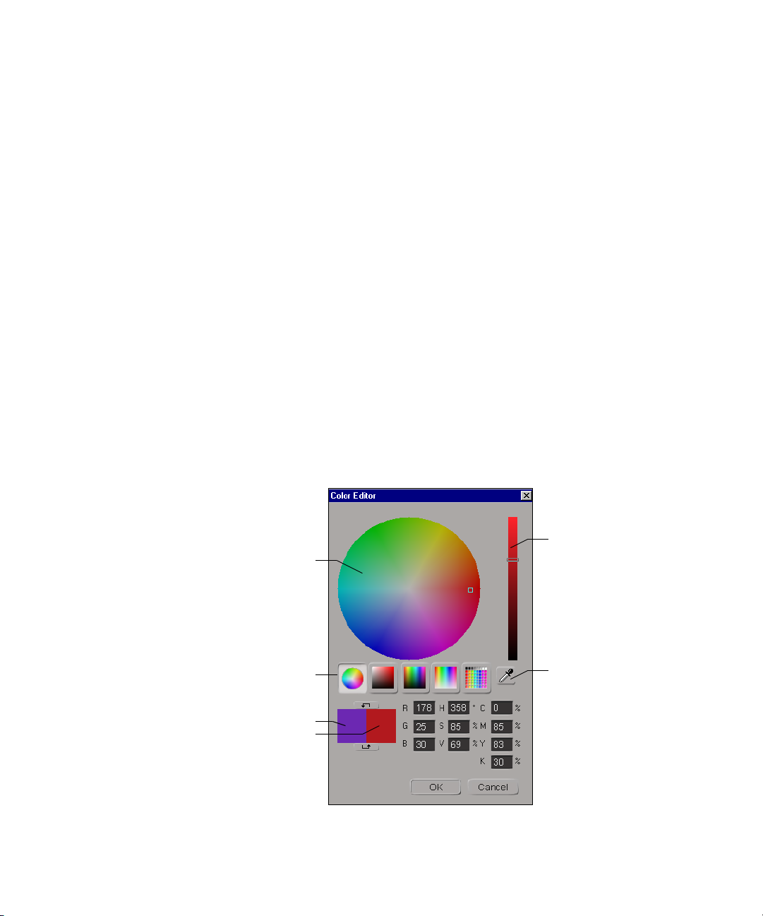
Chapter 3 The Avid 3D Interface
To edit a color:
t Use the slider bar at the right or enter a numeric value in the text boxes
below it. You can also change the color model from RGB to HLS to HSV
by clicking the > button.
To pick a color, do one of the following:
t Click the color picker button (the eye dropper) and click anywhere on the
screen. The color picker takes the color you see on the screen rather than the
true color of the objects. This tool can be especially useful when trying to
match a color in a viewport containing a flipbook or the Image Clip editor.
t Click on the browse (...) button to open the full color editor, where you
can fine-tune and create custom colors.
3. Close the color editor to use the color you created.
To fine-tune a color using the full color editor:
1. In a property editor, click the color box beside the color sliders to open the
mini color editor.
2. In the mini color editor, click the browse (...) button. The full color
editor opens.
94
Color area
Color views
Current
and Preview
color boxes
Slider bar
Color picker
Page 95

Defining Color Properties
To select a color:
t Click in the color area. You can define the color area by selecting a color
view mode. Each mode offers a variety of spectrums and hues. Once a
color is selected, the color appears in the preview color box, while the
previous color remains in the current color box to use as a reference.
To modify a color:
t Use the slider bar at the right of the color editor or enter a numeric value
in any one of the RGB, HSV, or CMYK fields. As a color is modified, its
corresponding values are updated.
To pick a color:
t Use the color picker as described on page 94.
95
Page 96

Chapter 3 The Avid 3D Interface
96
Page 97

Chapter 4
Avid 3D Basics
No matter what you plan to create in Avid 3D, the basic processes and
building blocks are the same. The library panel contains most of the raw
material you will use to create scenes, which you can then manipulate using
the processes described in this chapter.
Page 98

Chapter 4 Avid 3D Basics
Using the Library Panel
The library panel is where you find objects, textures, image and video clips,
camera effects, and more—most of the raw material you will be using to create
scenes in Avid 3D.
Getting content into your scene is simply a matter of dragging an item from a
library into a viewport or onto a node in the multi-purpose editor. However, the
type of content you want to use and how you want to apply it determines how
you should drag and drop. The following is a general guide to Avid 3D’s drag
and drop rules:
• To add objects, scenes, rigs, and environment effects, drag an item onto an
empty spot in a viewport.
• To add materials and textures to objects, drag an item onto the object.
• To add light or camera effects, do one of the following:
t Drag an item onto a specific light or camera.
t Drag an item into a viewport. The effect is added to all applicable
lights, or to the active camera.
98
n
• Some rigs use placeholder objects intended for objects you can add later.
Drag an item onto the placeholder to replace it.
When dragging and dropping items from the library, a status bar appears in
the active viewport and provides information appropriate to the location of
your mouse pointer.
You can also drag and drop files from a Windows explorer or Web browser into
Avid 3D.
Page 99

Using the Library Panel
• Sample Projects Library: Contains preset scenes that you can drag and
drop directly into a viewport. If you load a sample scene onto an existing
scene, you are prompted to save or cancel your existing scene. You cannot
merge the scenes together.
n
• Object Library: Contains preset elements that you can drag and drop
directly into a viewport. This includes static and animated objects, lights,
cameras, object rigs, environments, particle systems, text, and curves.
®
• Model Library and Digimation
object models that you can drag and drop directly into a viewport.
The Digimation Model Bank is available only if you selected to install it when
you installed Avid 3D.
• Material and Fx Library: Contains preset elements that you can drag
and drop onto an appropriate object (objects, particles, lights, or cameras)
or into a scene (environment maps). Most presets only work with specific
targets. For example, you can drag and drop materials only onto a 3D
object in a viewport, or drag and drop particle types only onto particles in
a viewport.
• Still Images Library: Contains 2D images and textures that you can drag
and drop onto a 3D object.
• Video Library: Contains video and audio clips that you can drag and
drop onto an object (video) or in the scene (audio).
Model Bank™: Contains various 3D
99
Page 100

Chapter 4 Avid 3D Basics
Basic Scene Elements
Objects
There are several different types of objects available for building Avid 3D
scenes. While many of them are the objects that will appear in your final
output, most will not—like a boom microphone or a wind machine on a sound
stage, these objects remain invisible to the audience but are necessary to create
a convincing and compelling scene.
Geometric Objects
Geometric objects are objects that can be modified by changing parameters or
manipulating the components (points or polygons) that make them up. By
default, most geometric objects are visible when the scene is rendered. There
are several different types of geometric objects in Avid 3D.
Polygon Meshes
Polygon meshes are quilts of polygons joined at their edges and points.
100
A polygon mesh sphere
Curves
Curves are one-dimensional objects that have points but no thickness. They
are not renderable, but can be used to modify extruded and revolved objects,
create paths for objects to move along, and so on.
A simple curve
 Loading...