

Page 1

Avid® 3D
Reference Guide
make manage move | media
™
Avid
®
Page 2

Copyright and Disclaimer
Product specifications are subject to change without notice and do not represent a commitment on the part
of Avid Technology, Inc.
The software described in this document is furnished under a license agreement. You can obtain a copy of
that license by visiting Avid's Web site at www.avid.com. The terms of that license are also available in the
product in the same directory as the software. The software may not be reverse assembled and may be
used or copied only in accordance with the terms of the license agreement. It is against the law to copy the
software on any medium except as specifically allowed in the license agreement.
Avid products or portions thereof are protected by one or more of the following United States Patents:
4,746,994; 4,970,663; 5,045,940; 5,063,448, 5,245,432, 5,267,351; 5,309,528; 5,325,200; 5,355,450;
5,396,594; 5,440,348; 5,452,378; 5,467,288; 5,513,375; 5,528,310; 5,557,423; 5,577,190; 5,584,006;
5,627,765; 5,634,020; 5,640,601; 5,644,364; 5,654,737; 5,701,404; 5,724,605; 5,726,717; 5,729,673;
5,731,819; 5,745,637; 5,752,029; 5,754,180; 5,754,851; 5,781,188; 5,799,150; 5,812,216; 5,828,678;
5,842,014; 5,852,435; 5,889,532; 5,912,675; 5,930,797; 5,966,134; 5,977,982; 5,995,079; 5,999,190;
6,011,562; 6,014,150; 6,023,703; 6,031,529; 6,091,422; 6,154,221; 6,157,929; 6,160,548; 6,167,404;
6,192,388; 6,208,357; 6,226,005; 6,310,621; 6,317,142; 6,353,437; 6,400,368; 6,466,214; 6,469,702;
6,473,094; 6,539,163; 6,552,731; 6,553,140; 6,570,578; 6,573,898; 6,621,504; 6,664,966; 6,686,918;
D352,278; D392,267; D392,268; D392,269; D395,291; D396,853; D398,912. Other patents are pending.
No part of this document may be reproduced or transmitted in any form or by any means, electronic or
mechanical, including photocopying and recording, for any purpose without the express written permission
of Avid Technology, Inc.
Copyright © 2004 Avid Technology, Inc. and its licensors. All rights reserved. Printed in USA.
The Avid 3D application uses JScript and Visual Basic Scripting Edition from Microsoft Corporation.
Attn. Government User(s). Restricted Rights Legend
U.S. GOVERNMENT RESTRICTED RIGHTS. This Software and its documentation are “commercial
computer software” or “commercial computer software documentation.” In the event that such Software or
documentation is acquired by or on behalf of a unit or agency of the U.S. Government, all rights with
respect to this Software and documentation are subject to the terms of the License Agreement, pursuant to
FAR §12.212(a) and/or DFARS §227.7202-1(a), as applicable.
Trademarks
888 I/O, Adrenaline, AirPlay, AirSPACE, AirSPACE HD, AniMatte, AudioSuite, AudioVision, AutoSync, Avid,
Avid DNA, AVIDdrive, AVIDdrive Towers, Avid Mojo, AvidNet, AvidNetwork, AVIDstripe, Avid Unity,
Avid Xpress, AVoption, AVX, CamCutter, ChromaCurve, ChromaWheel, DAE, D-Fi, D-fx, Digidesign,
Digidesign Audio Engine, Digidesign Intelligent Noise Reduction, DigiDrive, Digital Nonlinear Accelerator,
DigiTranslator, DINR, dotXSI, D-Verb, Equinox, ExpertRender, FieldPak, Film Composer, FilmScribe,
FluidMotion, HIIP, HyperSPACE, HyperSPACE HDCAM, IllusionFX, Image Independence, Intraframe, iS9,
iS18, iS23, iS36, Lo-Fi, Magic Mask, make manage move | media, Marquee, Matador, Maxim, MCXpress,
Media Composer, MediaDock, MediaDock Shuttle, Media Fusion, Media Illusion, MediaLog,
Media Reader, Media Recorder, MEDIArray, MediaShare, Meridien, MetaSync, NaturalMatch, Nearchive,
NetReview, NewsCutter, Nitris, OMF, OMF Interchange, OMM, Open Media Framework,
Open Media Management, ProEncode, Pro Tools, QuietDrive, Recti-Fi, RetroLoop, rS9, rS18, Sci-Fi,
Softimage, Sound Designer II, SPACE, SPACEShift, Symphony, the Avid|DS logo, the XSI logo, Trilligent,
UnityRAID, Vari-Fi, Video Slave Driver, VideoSPACE, Xdeck, and XSI are either registered trademarks or
trademarks of Avid Technology, Inc. in the United States and/or other countries.
iNEWS, iNEWS ControlAir, and Media Browse are trademarks of iNews, LLC.
Digimation and Digimation Model Bank are either registered trademarks or trademarks of Digimation, Inc.
in the United States and/or other countries.
mental ray and mental images are registered trademarks of mental images GmbH & Co. KG in the U.S.A.
and some other countries. All other trademarks contained herein are the property of their respective owners.
2
Page 3

GOT FOOTAGE?
Editors — Filmmakers — Special Effects Artists — Game Developers — Animators — Educators —
Broadcasters — Content creators of every genre — Just finished an incredible project and want to
share it with the world?
Send us your reels and we may use your footage in our show reel or demo!*
For a copy of our release and Avid’s mailing address, go to www.avid.com/footage.
*Note: Avid cannot guarantee the use of materials submitted.
Avid 3D Reference Guide • 0130-06297-01 • June 2004
3
Page 4

4
Page 5

Contents
Using This Guide. . . . . . . . . . . . . . . . . . . . . . . . . . . . . . . . . . . . . . . 13
Symbols and Conventions . . . . . . . . . . . . . . . . . . . . . . . . . . . . . . . . . . . . . . 14
If You Need Help. . . . . . . . . . . . . . . . . . . . . . . . . . . . . . . . . . . . . . . . . . . . . . 15
Accessing the Online Library . . . . . . . . . . . . . . . . . . . . . . . . . . . . . . . . . . . . 15
How to Order Documentation . . . . . . . . . . . . . . . . . . . . . . . . . . . . . . . . . . . . 16
Avid Educational Services. . . . . . . . . . . . . . . . . . . . . . . . . . . . . . . . . . . . . . . 16
Chapter 1 Commands and Interface Reference . . . . . . . . . . . . . . . . . . . . . . . 17
Main Window Overview. . . . . . . . . . . . . . . . . . . . . . . . . . . . . . . . . . . . . . . . . 18
Menu Bar. . . . . . . . . . . . . . . . . . . . . . . . . . . . . . . . . . . . . . . . . . . . . . . . . . . . 19
File Menu . . . . . . . . . . . . . . . . . . . . . . . . . . . . . . . . . . . . . . . . . . . . . . . . 19
Edit Menu . . . . . . . . . . . . . . . . . . . . . . . . . . . . . . . . . . . . . . . . . . . . . . . . 21
Layouts Menu. . . . . . . . . . . . . . . . . . . . . . . . . . . . . . . . . . . . . . . . . . . . . 22
Help Menu . . . . . . . . . . . . . . . . . . . . . . . . . . . . . . . . . . . . . . . . . . . . . . . 22
Control Bar . . . . . . . . . . . . . . . . . . . . . . . . . . . . . . . . . . . . . . . . . . . . . . . . . . 23
Lower Interface Controls . . . . . . . . . . . . . . . . . . . . . . . . . . . . . . . . . . . . . . . . 25
Timeline . . . . . . . . . . . . . . . . . . . . . . . . . . . . . . . . . . . . . . . . . . . . . . . . . 25
Playback Cursor . . . . . . . . . . . . . . . . . . . . . . . . . . . . . . . . . . . . . . . 26
Ruler . . . . . . . . . . . . . . . . . . . . . . . . . . . . . . . . . . . . . . . . . . . . . . . . 26
Start Frame Box . . . . . . . . . . . . . . . . . . . . . . . . . . . . . . . . . . . . . . . 27
End Frame Box . . . . . . . . . . . . . . . . . . . . . . . . . . . . . . . . . . . . . . . . 27
Timeline Range . . . . . . . . . . . . . . . . . . . . . . . . . . . . . . . . . . . . . . . . 27
Playback Controls . . . . . . . . . . . . . . . . . . . . . . . . . . . . . . . . . . . . . . . . . 28
Animation Controls . . . . . . . . . . . . . . . . . . . . . . . . . . . . . . . . . . . . . . . . . 29
Autokey (auto) Button . . . . . . . . . . . . . . . . . . . . . . . . . . . . . . . . . . . 30
Page 6

Contents
Previous/Next Key Button. . . . . . . . . . . . . . . . . . . . . . . . . . . . . . . . 30
Key Button . . . . . . . . . . . . . . . . . . . . . . . . . . . . . . . . . . . . . . . . . . . 30
Preview and Output Controls. . . . . . . . . . . . . . . . . . . . . . . . . . . . . . . . . 31
Flipbook. . . . . . . . . . . . . . . . . . . . . . . . . . . . . . . . . . . . . . . . . . . . . . . . . 32
Flipbook Command Bar . . . . . . . . . . . . . . . . . . . . . . . . . . . . . . . . . 32
Flipbook Playback Controls . . . . . . . . . . . . . . . . . . . . . . . . . . . . . . 34
Open Images Dialog Box . . . . . . . . . . . . . . . . . . . . . . . . . . . . . . . . 35
Export Dialog Box. . . . . . . . . . . . . . . . . . . . . . . . . . . . . . . . . . . . . . 36
Library Panel . . . . . . . . . . . . . . . . . . . . . . . . . . . . . . . . . . . . . . . . . . . . . . . . 37
Scene Explorer . . . . . . . . . . . . . . . . . . . . . . . . . . . . . . . . . . . . . . . . . . . 38
Sample Projects Library . . . . . . . . . . . . . . . . . . . . . . . . . . . . . . . . . . . . 38
Object Library . . . . . . . . . . . . . . . . . . . . . . . . . . . . . . . . . . . . . . . . . . . . 39
Model Library. . . . . . . . . . . . . . . . . . . . . . . . . . . . . . . . . . . . . . . . . . . . . 41
Digimation® Model Bank™ . . . . . . . . . . . . . . . . . . . . . . . . . . . . . . . . . . 41
Material & Fx Library . . . . . . . . . . . . . . . . . . . . . . . . . . . . . . . . . . . . . . . 42
Still Images Library . . . . . . . . . . . . . . . . . . . . . . . . . . . . . . . . . . . . . . . . 43
Video Library . . . . . . . . . . . . . . . . . . . . . . . . . . . . . . . . . . . . . . . . . . . . . 43
Tools and Options Panel . . . . . . . . . . . . . . . . . . . . . . . . . . . . . . . . . . . . . . . 44
Transform Tools Panel . . . . . . . . . . . . . . . . . . . . . . . . . . . . . . . . . . . . . 45
Animation Tools Panel. . . . . . . . . . . . . . . . . . . . . . . . . . . . . . . . . . . . . . 47
Text Tools Panel . . . . . . . . . . . . . . . . . . . . . . . . . . . . . . . . . . . . . . . . . . 49
Deformation Tools Panel. . . . . . . . . . . . . . . . . . . . . . . . . . . . . . . . . . . . 50
Particle Tools Panel. . . . . . . . . . . . . . . . . . . . . . . . . . . . . . . . . . . . . . . . 52
Display Options Panel . . . . . . . . . . . . . . . . . . . . . . . . . . . . . . . . . . . . . . 53
Options Panel . . . . . . . . . . . . . . . . . . . . . . . . . . . . . . . . . . . . . . . . . . . . 55
Viewports . . . . . . . . . . . . . . . . . . . . . . . . . . . . . . . . . . . . . . . . . . . . . . . . . . . 56
Letter Identifier Button . . . . . . . . . . . . . . . . . . . . . . . . . . . . . . . . . . . . . . 56
Views Menu. . . . . . . . . . . . . . . . . . . . . . . . . . . . . . . . . . . . . . . . . . . . . . 57
Display Types Menu . . . . . . . . . . . . . . . . . . . . . . . . . . . . . . . . . . . . . . . 58
Resize Viewport Icon. . . . . . . . . . . . . . . . . . . . . . . . . . . . . . . . . . . . . . . 59
6
Page 7

Contents
Multi-Purpose Editor . . . . . . . . . . . . . . . . . . . . . . . . . . . . . . . . . . . . . . . . . . . 60
Geometry and Deform Properties . . . . . . . . . . . . . . . . . . . . . . . . . . . . . 61
Material and Fx Properties . . . . . . . . . . . . . . . . . . . . . . . . . . . . . . . . . . . 61
Texture Clip Viewer . . . . . . . . . . . . . . . . . . . . . . . . . . . . . . . . . . . . . . . . 61
Profile Editor. . . . . . . . . . . . . . . . . . . . . . . . . . . . . . . . . . . . . . . . . . . . . . 62
Function Curve Editor. . . . . . . . . . . . . . . . . . . . . . . . . . . . . . . . . . . . . . . 63
Function Curve Editor Timeline . . . . . . . . . . . . . . . . . . . . . . . . . . . . 63
Function Curve Graph . . . . . . . . . . . . . . . . . . . . . . . . . . . . . . . . . . . 64
Function Curve Editor Command Bar . . . . . . . . . . . . . . . . . . . . . . . 64
Property Editors . . . . . . . . . . . . . . . . . . . . . . . . . . . . . . . . . . . . . . . . . . . . . . 67
Property Page Controls . . . . . . . . . . . . . . . . . . . . . . . . . . . . . . . . . . 68
Color Properties . . . . . . . . . . . . . . . . . . . . . . . . . . . . . . . . . . . . . . . . . . . 69
Browser . . . . . . . . . . . . . . . . . . . . . . . . . . . . . . . . . . . . . . . . . . . . . . . . . . . . . 71
The Tree View . . . . . . . . . . . . . . . . . . . . . . . . . . . . . . . . . . . . . . . . . . . . 71
Viewing Folder Contents . . . . . . . . . . . . . . . . . . . . . . . . . . . . . . . . . . . . 72
Setting Favorites . . . . . . . . . . . . . . . . . . . . . . . . . . . . . . . . . . . . . . . . . . 75
Accessing Files from the Browser Path Controls . . . . . . . . . . . . . . . . . . 75
Accessing Computers on a Network . . . . . . . . . . . . . . . . . . . . . . . . . . . 76
Chapter 2 Properties Reference . . . . . . . . . . . . . . . . . . . . . . . . . . . . . . . . . . . 77
General . . . . . . . . . . . . . . . . . . . . . . . . . . . . . . . . . . . . . . . . . . . . . . . . . . . . . 78
Color Editor Dialog Box . . . . . . . . . . . . . . . . . . . . . . . . . . . . . . . . . . . . . 78
Data Management Property Editor. . . . . . . . . . . . . . . . . . . . . . . . . . . . . 79
Display Property Editor. . . . . . . . . . . . . . . . . . . . . . . . . . . . . . . . . . . . . . 80
Environment Map Property Editor . . . . . . . . . . . . . . . . . . . . . . . . . . . . . 81
Inspect Source Paths Property Editor . . . . . . . . . . . . . . . . . . . . . . . . . . 83
Mini Color Editor. . . . . . . . . . . . . . . . . . . . . . . . . . . . . . . . . . . . . . . . . . . 83
New Project Dialog Box . . . . . . . . . . . . . . . . . . . . . . . . . . . . . . . . . . . . . 85
Project Manager Dialog Box. . . . . . . . . . . . . . . . . . . . . . . . . . . . . . . . . . 86
7
Page 8

Contents
3D Objects . . . . . . . . . . . . . . . . . . . . . . . . . . . . . . . . . . . . . . . . . . . . . . . . . . 87
Arc Property Editor . . . . . . . . . . . . . . . . . . . . . . . . . . . . . . . . . . . . . . . . 87
Circle Property Editor . . . . . . . . . . . . . . . . . . . . . . . . . . . . . . . . . . . . . . 88
Cluster Property Editor . . . . . . . . . . . . . . . . . . . . . . . . . . . . . . . . . . . . . 88
Cone Property Editor. . . . . . . . . . . . . . . . . . . . . . . . . . . . . . . . . . . . . . . 89
Cube Property Editor. . . . . . . . . . . . . . . . . . . . . . . . . . . . . . . . . . . . . . . 89
Cylinder Property Editor . . . . . . . . . . . . . . . . . . . . . . . . . . . . . . . . . . . . 89
Disc Property Editor. . . . . . . . . . . . . . . . . . . . . . . . . . . . . . . . . . . . . . . . 90
Extrusion Property Editor (Curve along Axis) . . . . . . . . . . . . . . . . . . . . 90
Extrusion Property Editor (Curve Along Curve). . . . . . . . . . . . . . . . . . . 93
Geometry Property Editor (Arc). . . . . . . . . . . . . . . . . . . . . . . . . . . . . . . 94
Geometry Property Editor (Circle) . . . . . . . . . . . . . . . . . . . . . . . . . . . . . 95
Geometry Property Editor (Cone) . . . . . . . . . . . . . . . . . . . . . . . . . . . . . 95
Geometry Property Editor (Cube) . . . . . . . . . . . . . . . . . . . . . . . . . . . . . 96
Geometry Property Editor (Cylinder) . . . . . . . . . . . . . . . . . . . . . . . . . . . 96
Geometry Property Editor (Disc) . . . . . . . . . . . . . . . . . . . . . . . . . . . . . . 97
Geometry Property Editor (Grid) . . . . . . . . . . . . . . . . . . . . . . . . . . . . . . 97
Geometry Property Editor (Sphere). . . . . . . . . . . . . . . . . . . . . . . . . . . . 98
Geometry Property Editor (Torus) . . . . . . . . . . . . . . . . . . . . . . . . . . . . . 98
Grid Property Editor. . . . . . . . . . . . . . . . . . . . . . . . . . . . . . . . . . . . . . . . 99
Loft Property Editor . . . . . . . . . . . . . . . . . . . . . . . . . . . . . . . . . . . . . . . . 99
Revolution Property Editor (Curve Around Axis) . . . . . . . . . . . . . . . . . 101
Revolution Property Editor (Curve Around Curve) . . . . . . . . . . . . . . . 103
Sphere Property Editor . . . . . . . . . . . . . . . . . . . . . . . . . . . . . . . . . . . . 104
Spiral Property Editor . . . . . . . . . . . . . . . . . . . . . . . . . . . . . . . . . . . . . 105
Square Property Editor . . . . . . . . . . . . . . . . . . . . . . . . . . . . . . . . . . . . 105
Torus Property Editor . . . . . . . . . . . . . . . . . . . . . . . . . . . . . . . . . . . . . 105
Deformations . . . . . . . . . . . . . . . . . . . . . . . . . . . . . . . . . . . . . . . . . . . . . . . 106
Bend Op Property Editor . . . . . . . . . . . . . . . . . . . . . . . . . . . . . . . . . . . 106
Bulge Op Property Editor. . . . . . . . . . . . . . . . . . . . . . . . . . . . . . . . . . . 107
8
Page 9

Contents
Curve Deform Property Editor . . . . . . . . . . . . . . . . . . . . . . . . . . . . . . . 108
Lattice Property Editor (Deformation). . . . . . . . . . . . . . . . . . . . . . . . . . 109
Lattice Property Editor (Lattice) . . . . . . . . . . . . . . . . . . . . . . . . . . . . . . 109
Push Op Property Editor . . . . . . . . . . . . . . . . . . . . . . . . . . . . . . . . . . . 110
QStretch Op Property Editor . . . . . . . . . . . . . . . . . . . . . . . . . . . . . . . . 111
Shape Jitter Op Property Editor . . . . . . . . . . . . . . . . . . . . . . . . . . . . . . 113
Shear Op Property Editor . . . . . . . . . . . . . . . . . . . . . . . . . . . . . . . . . . . 114
Taper Op Property Editor . . . . . . . . . . . . . . . . . . . . . . . . . . . . . . . . . . . 115
Twist Property Editor . . . . . . . . . . . . . . . . . . . . . . . . . . . . . . . . . . . . . . 117
Wave Property Editor . . . . . . . . . . . . . . . . . . . . . . . . . . . . . . . . . . . . . . 119
Wave Op Property Editor . . . . . . . . . . . . . . . . . . . . . . . . . . . . . . . . . . . 121
Text and Logos . . . . . . . . . . . . . . . . . . . . . . . . . . . . . . . . . . . . . . . . . . . . . . 122
Curve to Mesh Converter Property Editor . . . . . . . . . . . . . . . . . . . . . . 122
Text Property Editor . . . . . . . . . . . . . . . . . . . . . . . . . . . . . . . . . . . . . . . 126
Lights and Cameras . . . . . . . . . . . . . . . . . . . . . . . . . . . . . . . . . . . . . . . . . . 128
Ambient Lighting Property Editor . . . . . . . . . . . . . . . . . . . . . . . . . . . . . 128
Camera Property Editor . . . . . . . . . . . . . . . . . . . . . . . . . . . . . . . . . . . . 128
Depth of Field Property Editor . . . . . . . . . . . . . . . . . . . . . . . . . . . . . . . 129
Fisheye Property Editor . . . . . . . . . . . . . . . . . . . . . . . . . . . . . . . . . . . . 129
Flare Property Editor . . . . . . . . . . . . . . . . . . . . . . . . . . . . . . . . . . . . . . 130
Glow Property Editor . . . . . . . . . . . . . . . . . . . . . . . . . . . . . . . . . . . . . . 132
Light Property Editor. . . . . . . . . . . . . . . . . . . . . . . . . . . . . . . . . . . . . . . 135
Rig Controls Property Editor (Light Rig) . . . . . . . . . . . . . . . . . . . . . . . . 136
Light Rig Partial Property Editor (Light Rig) . . . . . . . . . . . . . . . . . . . . . 138
Key/Fill/Back Light Property Editor (Light Rig) . . . . . . . . . . . . . . . . . . . 139
Light Shader Property Editor . . . . . . . . . . . . . . . . . . . . . . . . . . . . . . . . 139
Volumic Property Editor . . . . . . . . . . . . . . . . . . . . . . . . . . . . . . . . . . . . 141
Z-Depth Property Editor . . . . . . . . . . . . . . . . . . . . . . . . . . . . . . . . . . . . 142
Materials and Textures . . . . . . . . . . . . . . . . . . . . . . . . . . . . . . . . . . . . . . . . 142
Image Source Property Editor . . . . . . . . . . . . . . . . . . . . . . . . . . . . . . . 142
9
Page 10

Contents
Material Property Editor. . . . . . . . . . . . . . . . . . . . . . . . . . . . . . . . . . . . 144
Texture Map Property Editor . . . . . . . . . . . . . . . . . . . . . . . . . . . . . . . . 146
Texture Support Property Editor . . . . . . . . . . . . . . . . . . . . . . . . . . . . . 147
Time Control Property Editor. . . . . . . . . . . . . . . . . . . . . . . . . . . . . . . . 148
Toon Shader Property Editor. . . . . . . . . . . . . . . . . . . . . . . . . . . . . . . . 151
Animation . . . . . . . . . . . . . . . . . . . . . . . . . . . . . . . . . . . . . . . . . . . . . . . . . . 155
Direction Constraint Property Editor . . . . . . . . . . . . . . . . . . . . . . . . . . 155
Fcurve Editor Property Editor . . . . . . . . . . . . . . . . . . . . . . . . . . . . . . . 156
Local Transform Property Editor . . . . . . . . . . . . . . . . . . . . . . . . . . . . . 157
Path Constraint Property Editor. . . . . . . . . . . . . . . . . . . . . . . . . . . . . . 158
Position Constraint Property Editor . . . . . . . . . . . . . . . . . . . . . . . . . . . 159
Time Property Editor . . . . . . . . . . . . . . . . . . . . . . . . . . . . . . . . . . . . . . 160
Particles . . . . . . . . . . . . . . . . . . . . . . . . . . . . . . . . . . . . . . . . . . . . . . . . . . . 161
Fan Property Editor . . . . . . . . . . . . . . . . . . . . . . . . . . . . . . . . . . . . . . . 161
Gravity Property Editor . . . . . . . . . . . . . . . . . . . . . . . . . . . . . . . . . . . . 162
10
Obstacle Property Editor . . . . . . . . . . . . . . . . . . . . . . . . . . . . . . . . . . . 163
Particle Billboard Property Editor. . . . . . . . . . . . . . . . . . . . . . . . . . . . . 164
Particle Emission Property Editor . . . . . . . . . . . . . . . . . . . . . . . . . . . . 167
Particle Gradient Property Editor. . . . . . . . . . . . . . . . . . . . . . . . . . . . . 168
Particle Shape Property Editor . . . . . . . . . . . . . . . . . . . . . . . . . . . . . . 170
Particle Sprite Property Editor . . . . . . . . . . . . . . . . . . . . . . . . . . . . . . . 173
Particle Type Property Editor. . . . . . . . . . . . . . . . . . . . . . . . . . . . . . . . 173
ParticlesOp Property Editor. . . . . . . . . . . . . . . . . . . . . . . . . . . . . . . . . 176
Turbulence Property Editor . . . . . . . . . . . . . . . . . . . . . . . . . . . . . . . . . 177
Wind Property Editor . . . . . . . . . . . . . . . . . . . . . . . . . . . . . . . . . . . . . . 179
Preview and Rendering . . . . . . . . . . . . . . . . . . . . . . . . . . . . . . . . . . . . . . . 179
Render Options Dialog Box. . . . . . . . . . . . . . . . . . . . . . . . . . . . . . . . . 179
Format Property Page . . . . . . . . . . . . . . . . . . . . . . . . . . . . . . . . . 184
AAF and MXF Options Property Page . . . . . . . . . . . . . . . . . . . . . 185
Rendering Property Editor. . . . . . . . . . . . . . . . . . . . . . . . . . . . . . . . . . 187
Page 11

Contents
Chapter 3 Keyboard Shortcuts . . . . . . . . . . . . . . . . . . . . . . . . . . . . . . . . . . . 189
General . . . . . . . . . . . . . . . . . . . . . . . . . . . . . . . . . . . . . . . . . . . . . . . . . . . . 189
Selection Tools . . . . . . . . . . . . . . . . . . . . . . . . . . . . . . . . . . . . . . . . . . . . . . 190
Transform Tools . . . . . . . . . . . . . . . . . . . . . . . . . . . . . . . . . . . . . . . . . . . . . 190
Camera Navigation and Framing Tools . . . . . . . . . . . . . . . . . . . . . . . . . . . 191
Display Options . . . . . . . . . . . . . . . . . . . . . . . . . . . . . . . . . . . . . . . . . . . . . . 191
Render Region . . . . . . . . . . . . . . . . . . . . . . . . . . . . . . . . . . . . . . . . . . . . . . 192
Playback Controls . . . . . . . . . . . . . . . . . . . . . . . . . . . . . . . . . . . . . . . . . . . . 192
Animation Controls . . . . . . . . . . . . . . . . . . . . . . . . . . . . . . . . . . . . . . . . . . . 192
Scene Explorer . . . . . . . . . . . . . . . . . . . . . . . . . . . . . . . . . . . . . . . . . . . . . . 193
Function Curve Editor . . . . . . . . . . . . . . . . . . . . . . . . . . . . . . . . . . . . . . . . . 193
Profile Editor . . . . . . . . . . . . . . . . . . . . . . . . . . . . . . . . . . . . . . . . . . . . . . . . 195
Browser . . . . . . . . . . . . . . . . . . . . . . . . . . . . . . . . . . . . . . . . . . . . . . . . . . . . 195
Index . . . . . . . . . . . . . . . . . . . . . . . . . . . . . . . . . . . . . . . . . . . . . . . . 197
11
Page 12

Contents
12
Page 13

Using This Guide
Congratulations on your purchase of the Avid 3D software. You can use
Avid 3D to create, customize, and animate 3D content, visual effects, text and
titling for your productions.
n
The documentation describes the features and hardware of all models.
Therefore, your system might not contain certain features and hardware that
are covered in the documentation.
This guide is intended for all Avid 3D users, from beginner to advanced. It
contains detailed interface, command and parameter information for all
aspects of the Avid 3D software.
Page 14

Using This Guide
Symbols and Conventions
Avid 3D documentation uses the following symbols and conventions:
Symbol or Convention Meaning or Action
n
c
w
> This symbol indicates menu commands (and
t
Margin tips
Italic font Italic font is used to emphasize certain words and to
Courier Bold font
Bold font Bold indicates a user interaction.
A note provides important related information,
reminders, recommendations, and strong suggestions.
A caution means that a specific action you take could
cause harm to your computer or cause you to lose data.
A warning describes an action that could cause you
physical harm. Follow the guidelines in this document
or on the unit itself when handling electrical equipment.
subcommands) in the order you select them. For
example, File > Import means to open the File menu
and then select the Import command.
This symbol indicates a single-step procedure.
Multiple arrows in a list indicate that you perform one
of the actions listed.
In the margin, you will find tips that help you perform
tasks more easily and efficiently.
indicate variables.
Courier Bold font identifies text that you type.
14
Ctrl+key or mouse action Press and hold the first key while you press the last
key or perform the mouse action. For example,
Shift+Alt+C or Ctrl+drag.
Page 15

If You Need Help
If you are having trouble using Avid 3D:
1. Retry the action, carefully following the instructions given for that task in
this guide. It is especially important to check each step of your workflow.
2. Check for the latest information that might have become available after
the documentation was published in one of two locations:
- If release notes are available, they ship with your application.
- If ReadMe files are available, they are supplied in your Avid
If You Need Help
application folder. ReadMe files are also available from Help.
n
Release notes and ReadMe files are also available from the Knowledgebase.
3. Check the documentation that came with your Avid application or your
hardware for maintenance or hardware-related issues.
4. Visit Avid Online Support at www.avid.com/support. Online support is
available 24 hours per day, 7 days per week. Search the Knowledgebase to
find answers, to view error messages, to access troubleshooting tips, to
download updates, and to read/join online message-board discussions.
5. For Technical Support, please call 800-800-AVID (800-800-2843).
For Broadcast On-Air Sites and Call Letter Stations, call
800-NEWSDNG (800-639-7364).
Accessing the Online Library
The Avid 3D Online Library contains all the product documentation in PDF
format as well as a selection of movies for getting started. Avid recommends
the movies as your first resource for learning how to use your application.
n
You will need Adobe® Acrobat® Reader® installed to view the documentation
online. You can download the latest version of the Reader from the Adobe
Web site.
®
To access the documentation from the Online Library:
1. Insert the Online Library into the drive.
2. Double-click the Mainmenu file.
15
Page 16

Using This Guide
How to Order Documentation
To order additional copies of this documentation from within the
United States, call Avid Sales at 800-949-AVID (800-949-2843). If you are
placing an order from outside the United States, contact your local
Avid representative.
Avid Educational Services
For information on courses/schedules, training centers, certifications,
courseware, and books, please visit www.avid.com/training or call Avid Sales
at 800-949-AVID (800-949-2843).
16
Page 17

Chapter 1
Commands and Interface Reference
Page 18
Chapter 1 Commands and Interface Reference
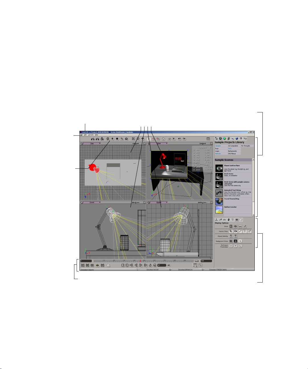
Main Window Overview
The Avid 3D interface is made up of control panels and four viewports, many
of which can be resized.
Title bar
Displays the name of the
open project and scene.
Menu bar Provides
access to primary
project and editing
commands.
Control bar
Displays buttons for
one-click access to
camera,
transformation, and
editing controls.
Viewports
Let you view the contents of your
scene in different ways. You can
resize, hide, and mute viewports in
any combination.
Library panel
Contains objects, materials, textures,
images, and video clips you can use
to create your scene. This panel is
also home to the scene explorer.
18
Lower interface controls
Tools and Options panel
Provides tools for modifying and
animating elements in your scene,
as well as setting user preferences
and display and output options.
Page 19

Menu Bar
File Menu
Menu Bar
The menu bar is the horizontal bar at the top of the main window that displays
menus containing commands that are general to Avid 3D. These include
general operations such as managing files, editing, and getting help.
Location: At the top of the main window.
Create and open projects; create, open, close, and save project scenes; import
and export models and scenes, and exit.
Location: Menu bar
Option Description
New Scene Creates a new scene. Acts as a “delete all” command: The
current scene is removed from the workspace and a new empty
scene is created. By default, the empty scene is named
“Untitled.” When you select this command, you are prompted to
save and close the current scene.
Open Opens a browser that lets you locate and load an existing scene.
When you select this command, you are prompted to save and
close the current scene.
Save Saves your scene and all rendering properties and options as a
scene file using the current scene file name.
If you have not previously saved your scene (“Untitled”), a
browser is displayed in which you can specify a scene name. A
scene is saved with an .scn extension to the Scenes folder of the
current project folder.
Save As Opens a browser that lets you save your scene to a different
name. A scene is saved with an .scn extension to the Scenes
folder of the current project folder.
New Project Creates a new project. This command opens the New Project
dialog box where you can set a name and location for your project
folder. Scenes are always associated with a particular project.
19
Page 20

Chapter 1 Commands and Interface Reference
Option Description
Project Manager Opens the Project Manager dialog box, which displays a list of
available projects and scenes. You can select an existing project
from the list, delete projects, and add projects to the list that may
exist elsewhere in your system or network.
If you choose a project to work on, you can either choose a
scene you want to load or create a new scene. You are prompted
to save and close the current project and scene before the next
project and scene are loaded.
Source Paths Opens the Inspect Source Paths property editor, where you can
verify your scene's links to external files and, if necessary,
modify them.
Import Model Opens a browser that lets you import an exported
SOFTIMAGE|XSI or Avid 3D model. Exported models are
identified by their .emdl extensions.
Import dotXSI File Imports elements from a dotXSI (.xsi) file.
Import EPS File Imports curves from an encapsulated PostScript file (.eps).
20
Export Model Opens a browser for exporting a selected model. Exported
models are saved to the Models folder under the project with the
.emdl extension.
Recent Scenes Lists scenes you have worked on recently. Select a scene to
open it.
Recent Models Lists models you have imported recently. Select a model to
import it into the current scene as a non-referenced model.
Exit Closes the Avid 3D program. You are prompted to save changes
to your current scene before exiting.
Page 21

Edit Menu
Menu Bar
Perform common editing and organizational tasks on selected elements within
your scene.
Location: Menu bar
Option Description
Repeat Repeats the last repeatable command.
The name of the menu item indicates which command will be repeated.
Certain categories of commands cannot be repeated:
• Selection commands. This allows you to apply a command to selected
elements, then select other elements and repeat the command.
• Interactive manipulation, for example, using the transform tools (V,
C, X) or the Move Point tool (M). However, transformation values
entered numerically in the Local Transform property editor or onscreen parameters can be repeated.
• Viewing commands, such as toggling the display type in a viewport.
• Playback and timeline commands, such as changing frames.
• Camera navigation and viewing commands, such as orbiting,
zooming, and framing.
When the last command can't be repeated, Edit > Repeat will repeat the
previous command instead.
Note that you can also repeat the last command from a specific
n
menu button by middle-clicking on the menu button.
Undo Cancels the last action that was performed. You can perform multiple undo's.
Redo Reapplies the action you previously canceled with the Undo command.
Cut Removes the current selection and copies it to the Clipboard.
Copy Duplicates the current selection and copies it to the Clipboard.
Paste Inserts a copy of the Clipboard contents, replacing the current selection
(if any) with the contents of the Clipboard.
Select All Selects all elements in the current scene.
21
Page 22

Chapter 1 Commands and Interface Reference
Layouts Menu
Switches between a single and dual-screen layout.
Location: Menu bar
Option Description
Avid 3D Main - Single Displays Avid 3D on a single screen.
Avid 3D Main - Autohide Hides the library and tools and options panels when they
Avid 3D Main - Dual Displays Avid 3D on two side-by-side screens.
Help Menu
Access to Online Help, which contains information on commands, properties,
and the interface; access to the Softimage and Avid web sites, where you can
perform web searches and send technical questions to Avid Customer Support
by e-mail.
are not in use. Move the mouse pointer to the right edge of
the screen to display a panel.
22
Location: Menu bar
Option Description
Avid® 3D Help Opens the Online Help window's Contents tab, which
displays help topics listed by category. This window also
has an Index tab for alphabetical topic searches, and a
Search tab for full-text searches.
Softimage Home Page Opens your web browser to the Softimage home page.
Avid Home Page Opens your web browser to the Avid home page.
About Avid 3D Provides product information, including version number.
Page 23
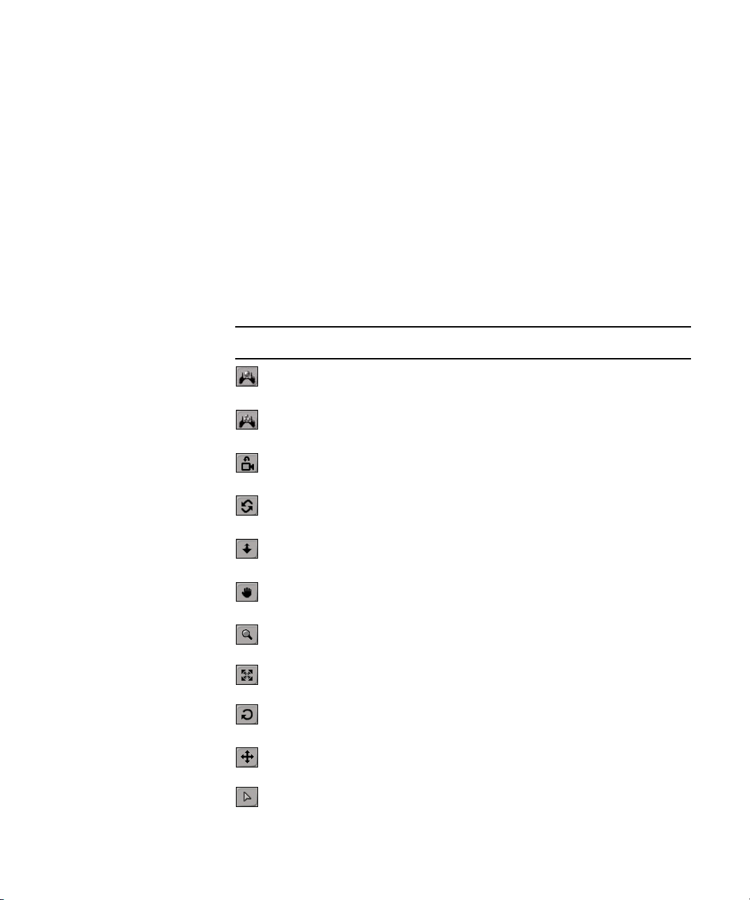
Control Bar
Control Bar
The control bar gives you quick access to many commands that are in the form of
buttons. Many of these buttons have associated menu commands or shortcut keys.
The control bar includes buttons for navigating in the viewports, transforming
scene elements, selecting scene elements and their various components,
duplicating and deleting scene elements, undoing and redoing edits, and
opening the multi-purpose editor for editing properties.
Location: Above the viewports at the top of the main window.
Button Tool Description
Frame Selection Zooms instantly into or out from selected
elements in your scene.
Frame All Zooms instantly into or out from all elements in
your scene.
Reset Camera Resets the view to its original viewpoint and pan
& zoom state.
Orbit Camera Pivots a camera, spotlight, or user view around its
point of interest.
Dolly Camera Dollies toward or away from the center of a
viewport.
Pan Camera Moves the camera horizontally or vertically
without changing its depth.
Zoom Camera Zooms into or out of the scene.
Scale Changes the size of selected elements.
Rotate Rotates (changes the orientation) of selected
elements.
Translate Moves (positions) selected elements.
Select Selects objects.
23
Page 24
Chapter 1 Commands and Interface Reference
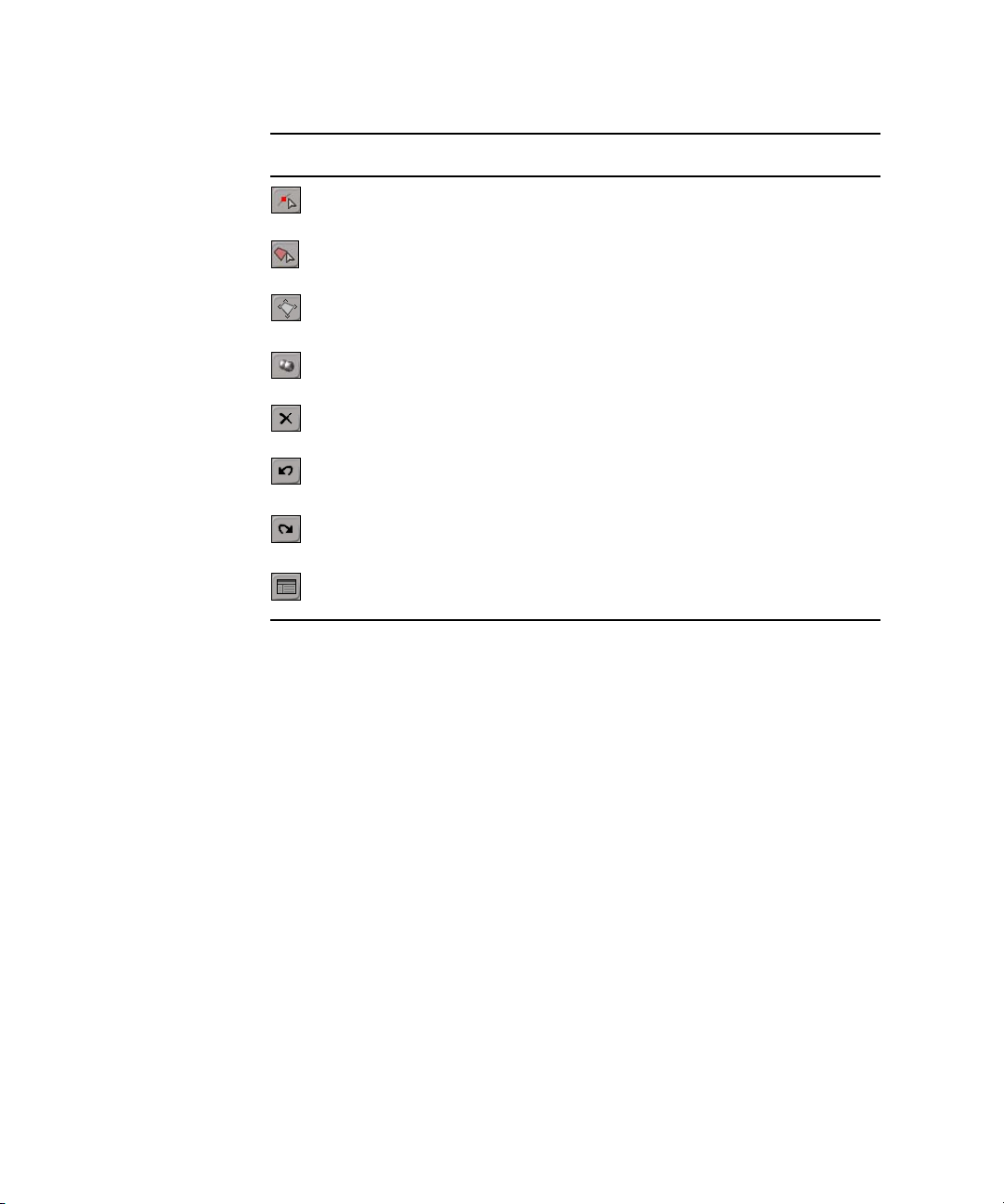
Button Tool Description
Select Point Selects points on selected objects.
Select Polygon Selects polygons on selected objects.
Create and Manage
Polygon Clusters
Duplicate Creates copies of selected objects.
Delete Removes selected elements from the scene.
Undo Cancels the last action that was performed. You
Redo Reapplies the action you previously canceled
Multi-Purpose Editor Opens or closes the display of the
Creates, selects, and deletes clusters of polygons
on selected objects.
can perform multiple undo's.
with the Undo command.
multi-purpose
editor
.
24
Page 25
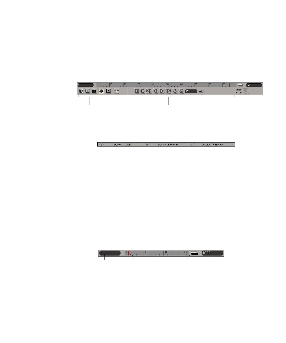
Lower Interface Controls
This area of the interface gives you access to the timeline and playback
controls; basic keyframe animation controls; and preview and rendering
controls, as well as a status line for information.
Lower Interface Controls
Timeline
Rendering and
Preview Controls
Let you set up and
create rendered output
of your scene.
The timeline comprises a ruler, a playback cursor (vertical red bar), a range
control, and start and end frame boxes. The timeline represents the length of
an animation scene and is used to display the current playback position, set the
current position for keyframing properties, and manually move forward or
backward to a different part of the animation.
Timeline
Displays the current
position of your
animation in time and
lets you move
manually between
Mouse/status line
Displays the current functions of your three
mouse buttons as well as status and error
messages when applicable.
Playback controls
Let you play back
animated scenes.
Animation controls
Let you set, remove, edit
and navigate between
keyframes.
Start frame
Playback cursor
Ruler
Timeline range
End frame
Time is displayed in frames, seconds, or milliseconds, depending on the
option you set in the Time Format Options (see “Options Panel” on page 55).
25
Page 26

Chapter 1 Commands and Interface Reference
By default, the first and last frame of the scene is displayed in the start and end
frame boxes at either end of the timeline. You can view a specific section of
time by changing the frame number in either of these boxes. The current
frame/time, as indicated by the position of the playback cursor, is displayed in
the current framed/time box in the playback controls.
When you click the Loop button in the playback controls, yellow markers
appear in the timeline, showing the frame range of the loop.
Location: Below the viewports at the bottom of the main window.
Playback Cursor
A red vertical bar on the timeline indicating the playback position, it displays
the various frames in a scene.
You can drag the playback cursor manually, or you can play back animation
using the playback commands. When you play back an animated scene, the
cursor moves along the timeline.
• Dragging the playback cursor changes the frame. The current frame box
displays the current frame at which the cursor is located.
Ruler
26
• Middle-click+dragging the playback cursor moves to the selected frame but
does not update the viewports until you release the button. This means you
can quickly drag to the required frame while avoiding lengthy refresh time.
• Right-click+dragging the playback cursor also moves to the selected
frames without updating the scene. The cursor and frame number in the
current frame box turn green. To refresh the scene, click the cursor. This
is useful for copying keys from one frame to another.
Location: Timeline
Displays the time scale for your animated scene and is used as a guide when
setting keyframes or defining rendering tasks.
The time scale can display in frames, seconds, and milliseconds, depending on
the option you set in the Time Format Options (see “Options Panel” on page 55).
Location: Timeline
Page 27

Start Frame Box
End Frame Box
Lower Interface Controls
Indicates the beginning of the current animated scene.
You can set the start frame value to begin at any point in your scene's timeline.
This value is used by the playback commands and controls (such as Play and
Go to First Frame).
This value is expressed in frames, seconds, or milliseconds, depending on the
settings you set in the Time Format Options (see “Options Panel” on page 55).
Location: Left end of timeline
Indicates the end of the current animated scene.
You can set the end frame value to end at any point in your scene's timeline.
However, the value in the end frame box must be greater than the value in the
start frame box for the animation to play. This value is used by the playback
commands and controls (such as play and go to last frame).
Timeline Range
This value is expressed in frames, seconds, or milliseconds, depending on the
settings you set in the Time Format Options (see “Options Panel” on page 55).
Location: Right end of timeline
Allows you to see and adjust the range relative to the overall animation.
Click this icon (or Alt+click on the timeline) at the right end of the timeline to
display the range control. Then do any of the following:
• Drag on the left, right, or middle handles to adjust the playback's in/out time.
• Click+drag in the range’s middle to slide the time range.
• Click this icon again (or Alt+click on the timeline) to return to the
timeline display.
Location: Right end of timeline
27
Page 28
Chapter 1 Commands and Interface Reference
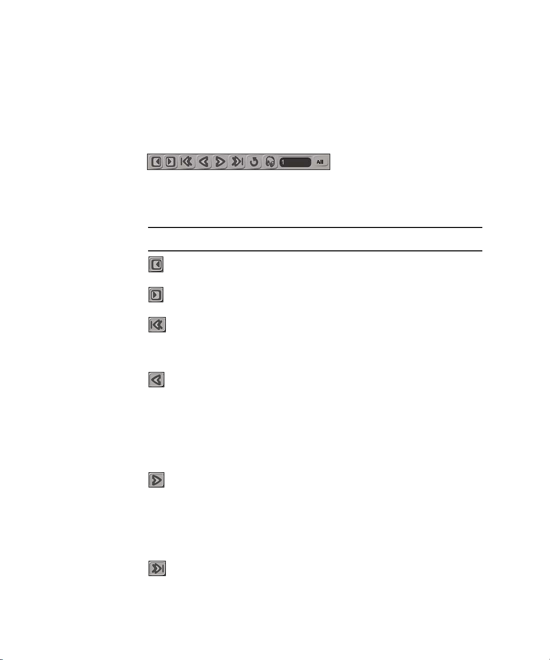
Playback Controls
Controls how the animation and audio in the scene is played back. You can
play the scene forward, stop playback, go to the first frame and last frame, go
to the previous or next frame, and set real-time playback.
Location: Below the timeline at the bottom of the main window.
Button Tool Description
Previous Frame Moves you back in the scene by one frame.
Next Frame Moves you forward in the scene by one frame.
Go to First Frame Returns the playback cursor to the first frame of the
scene. The first frame of your scene is set according
to the value in the Start frame box at the beginning
of the timeline.
28
Play Backward Toggles between playing the scene animation in
reverse and stopping it.
• Left-clicking the Play Backward button plays
the animation backward from the last frame on
the timeline.
• Middle-clicking the Play Backward button plays
the animation backward from the current frame.
Play Forward Toggles between playing the scene animation
forward and stopping it.
• Left-clicking the Play button plays the animation
forward from the first frame on the timeline.
• Middle-clicking the Play button plays the
animation forward from the current frame.
Go to Last Frame Returns the playback cursor to the last frame of the
scene. The last frame of your scene is set according
to the value in the End frame box at the end of the
timeline.
Page 29
Button Tool Description
Loop Animation Continuously repeats the scene animation in one
continuous loop. The frame numbers in the start
frame and end frame boxes set the range for the loop.
When you click the Loop button, yellow markers
appear on the timeline showing the frame range of
the loop. To change the range, drag the yellow
markers to different frames.
Audio Toggles between playing and muting any audio files.
Audio is active by default (button is gray). When the
audio is muted, the button is highlighted.
Current Frame Box Displays the current frame number or time position
in the sequence. As you move the playback cursor,
the time/frame box displays the frame or time
position at which the cursor is located. You can also
enter a specific frame number in this box to go to
that frame.
All/RT Toggles between playing back the animated scene
frame by frame (All) or in real time (RT).
Lower Interface Controls
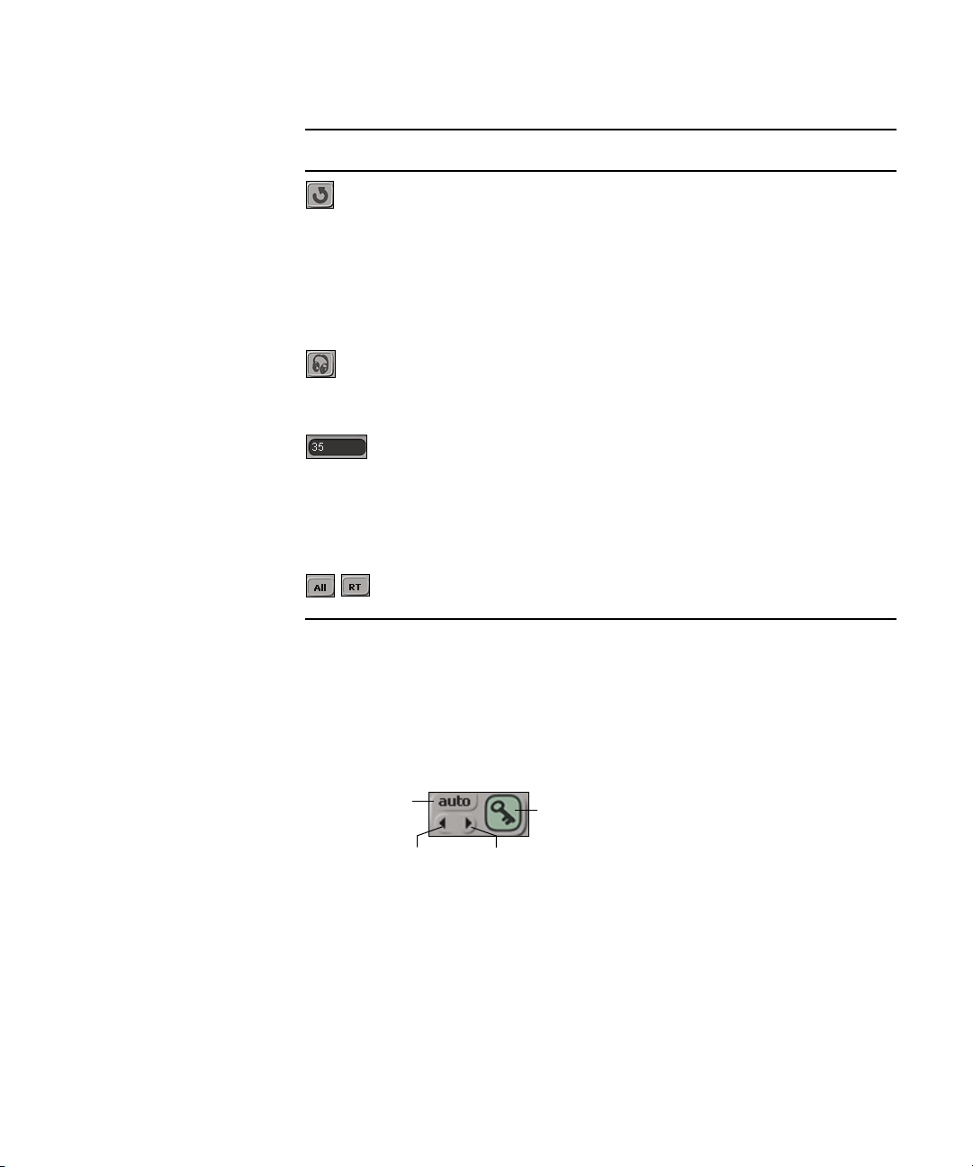
Animation Controls
You can use the various command buttons to animate properties and objects
such as lights and cameras. You can set and delete keys, and quickly move
through keys.
Autokey button
Location: Below the timeline at the lower-right of the main window.
Key button
Previous and next key buttons
29
Page 30

Chapter 1 Commands and Interface Reference
Autokey (auto) Button
Toggles autokey mode on and off. In autokey mode, keys are generated
automatically for individual parameters as you change settings.
When autokey mode is on, the button is highlighted in red.
Location: Animation controls
Previous/Next Key Button
Moves to the previous or next keyframe for a selected object's parameters,
marked or not.
• If the selected object has marked parameters, the buttons move between
the keys for those parameters.
• If nothing is marked, the buttons move between keys for all parameters of
the selected object.
Location: Animation controls
Key Button
30
Sets or removes keys on the marked parameters at the current frame:
• If there is no key at the current frame, clicking the Key button sets a key.
• If there is a key at the current frame, clicking or middle-clicking the Key
button removes that key.
The color of the button shows the status of the marked parameters at the
current frame:
• None: There is no fcurve animation on the marked parameters.
• Red: There is a key on the current values at the current frame.
• Green: There is no key at the current frame, but the current values are as
determined by the function curve.
• Yellow: The current values are different from those determined by the
function curve.
Location: Animation controls
Page 31

Preview and Output Controls
Provides different options for previewing and rendering your work. You can
create a render region to preview part of your scene while you work, or render
all of your scene at different levels of quality. The higher the quality settings,
the longer it takes to render.
Location: Lower interface controls
Button Tool Description
Render Low-Quality Opens the Render Options dialog box with the
Render High-Quality Opens the Render Options dialog box with the
Lower Interface Controls
Render Type and Quality parameters set for a lowquality image. These settings are best for
previewing your work, and images render quickly.
Render Type and Quality parameters set for a highquality image. These settings are best for a final or
near-final render.
Preview Render Renders only the current frame, using the Render
High-Quality settings.
Render Region Activates render region mode and lets you draw a
region in any of the displayed viewports. You
create the render region by dragging the mouse
pointer across the viewport. As soon as you release
the mouse button, the region is drawn and
whatever is displayed in that region is rendered.
Open Flipbook Launches the standalone flipbook, which lets you
view and convert still images and video clips.
Inspect Render
Options
Opens the Render Options dialog box.
31
Page 32

Chapter 1 Commands and Interface Reference
Flipbook
The standalone flipbook displays a series of cached images for checking
animation sequences or still images. You can load video files (AVI,
QuickTime, or AAF/MXF), a series of images that have been saved as .pic
files, or single images (GIF, JPEG, TIFF, etc.). This view provides a set of
playback controls.
To display the flipbook:
1. Click the Open Flipbook button in the preview and output controls.
2. In the Open Images dialog box that appears, specify the path and File
name of the images you want to load—click the browser button (...) to
open the browser.
3. Set the options in the dialog box, then click OK to load the image
sequence and open the flipbook window.
The flipbook window is resized if the loaded image is larger than the
current size.
Flipbook Command Bar
32
These commands let you load, export, and set up how the flipbook is played back.
Option Description
File
Open Images Opens the Open Images dialog box, where you can specify
which image or video file you want to load as well as set
up how you want to play it back. You can also press
Ctrl+O to open this dialog box.
Export Opens the Export dialog box, where you can select how to
export the currently cached sequence in a number of
formats, such as AVI, SOFTIMAGE, QuickTime, etc. You
can also press Ctrl+E to open this dialog box.
Clear Flipbook Clears the flipbook window of the current cached images.
Exit Closes the flipbook window. You can also press Alt+F4.
Page 33

Lower Interface Controls
Option Description
View
Channel Displays a menu of channels you can view separately: red,
green, blue, or alpha. All Channels are selected by default.
You can also press the R, G, B, A, or C (all channels) keys
to display the respective channels.
Zoom Displays a menu of zoom factors you can set to view the
current images: 50, 100 (default), 200, or 400% of the
image size.
Correct Aspect Ratio Stretches the image so that non-square pixels appear
correctly on the computer monitor, which has square
pixels. For example, NTSC images have a pixel ratio of
0.9, meaning the pixels are not square.
Play Real-Time Plays the image sequence in real time. For example, if you
have a 5-second loop, it takes exactly 500 seconds to loop
the sequence 100 times. You can also press the T key to
activate real time.
Ping-Pong Plays the image sequence in ping-pong style. This reverses
the direction of a looped playback at the first and last
frames of the sequence.
Background Color Opens the color editor in which you can set the
background color of the flipbook.
Disable Redraw
Vertical Sync
Disables synchronizing the redraw to the vertical retrace of
the display monitor (if the graphics hardware supports
this) so that you can achieve higher frame rates at the
expense of visual quality.
Image Format Lets you change the image format for the images loaded in
the flipbook: Automatic, RGB, or RGBA. RGBA may
give better performance on newer hardware systems.
Tools
Rate Opens a dialog box in which you can select a playback
rate: NTSC, PAL, film, etc. You can also press Ctrl+R to
open this dialog box.
Go to Frame Opens a dialog box in which you can enter the frame you want
to display. You can also press Ctrl+G to open this dialog box.
33
Page 34

Chapter 1 Commands and Interface Reference
Option Description
Increase Rate Increases the playback rate by one frame per second. You
Decrease Rate Decreases the playback rate by one frame per second.
Help
can adjust the playback rate by 1 fps (frame per second)
increments within the range of 24 and 30 fps.
Command Line
Options
About Shows the copyright information for the flipbook.
Flipbook Playback Controls
Button Option Description
Displays the command line options you can specify when
running the flipbook as a standalone program. The basic
syntax for running a flipbook is:
flip <sequence_name>.<ext> <start> <end> [step] [rate] [options]
Previous Frame Moves you back in the animation sequence by
one frame.
Next Frame Moves you forward in the animation sequence by
one frame.
Go to Start Goes to the first frame of the animation sequence.
Play Backward/Stop Plays the animation sequence in reverse from the
current frame. Click again to stop or press the
down-arrow key.
Play Forward/Stop Plays the animation sequence forward from the
current frame. Click again to stop. You can also
press the up-arrow key to play and the down-arrow
key to stop.
34
Go to End Goes to the last frame of the animation sequence.
Loop Animation Continuously repeats the animation sequence in
one continuous loop.
Page 35

Open Images Dialog Box
To display: Choose File > Open Images in the flipbook window.
Option Description
File name File name of the images to load. Click the (...) button to
Type
Lower Interface Controls
open the browser and search for the images
Images/Movies Loads a single image or the complete image sequence of the
file that you are loading.
Sequence Loads a specific range of frames in the image file you are
loading. Include the Step (frames to be skipped, for
example 2 skips every other frame) and the playback Rate
(NTSC, PAL, etc.).
Number Padding Adds numbers to the frame numbers so you can match up
image sequences. The default syntax is [fn].#[ext], where
fn is the base file name, ext is the file format extension, and
# is the frame number.
Zoom Factors
Shrink on load Divides the image resolution by a value that you specify.
For example, if you enter 2, the images are loaded at half
the original resolution. The values must be integers.
Magnify on display Multiplies the image resolution by a value that you specify.
For example, if you enter 2, the images are loaded at twice
the original resolution. The values must be integers.
Keep images in memory Caches the images in memory so that they can be played
back in real time.
Preload before playing Loads the entire image sequence into memory instead of
loading frames on demand.
Play Real Time Plays the image sequence in real time. For example, if you
have a 5-second loop, it takes exactly 500 seconds to loop
the sequence 100 times. When you select this option, RT is
activated on the playback controls below the timeline and
you can see the frame rate displayed.
35
Page 36

Chapter 1 Commands and Interface Reference
Export Dialog Box
To display : Choose File > Export in the flipbook window.
Option Description
File name File name of the images to load. Click the (...) button to
File Type Exports the file in a number of formats, including AVI,
Codec The codec (compressor/decompressor) to use when
Source Range Range of frames to export.
Movie Settings
Audio File Exports an accompanying audio file with the images.
open the browser and search for the images
QuickTime, etc.
creating movie files.
Click the (...) button to open the browser and search for
the audio file.
36
Image Settings
Number padding Adds numbers to the frame numbers to allow you to
match up image sequences. The default syntax is
[fn].#[ext], where fn is the base file name, ext is the
file format extension, and # is the frame number.
Destination Frame Offset Adds the number of frames you specify to the
destination images. For example, you can offset the
image sequence before using another tool.
Page 37

Library Panel
The library panel is where you find objects, textures, image and video clips,
camera effects, and more—most of the raw material you will be using to
create scenes in Avid 3D.
The library panel is found on the right side of the Avid 3D interface. It is
divided into tabs that contain libraries of objects, rigs, clips, particles, and
other elements that can be used as building blocks for Avid 3D scenes.
Library Panel
Object library Model library
Sample Projects library
Scene explorer
Digimation
Model Bank
Material and Fx
library
Still Images library
Video library
Getting content into your scene is simply a matter of dragging an item from a
library into a viewport or onto a node in the multi-purpose editor. However,
the type of content you want to use and how you want to apply it determines
how you should drag and drop. The following is a general guide to Avid 3D’s
drag and drop rules:
• To add objects, scenes, rigs, and environment effects, drag an item onto
an empty spot in a viewport.
• To add materials and textures to objects, drag an item onto the object.
• To add light or camera effects, do one of the following:
t Drag an item onto a specific light or camera.
t Drag an item into a viewport. The effect is added to all applicable
lights, or to the active camera.
37
Page 38

Chapter 1 Commands and Interface Reference
• Some rigs use placeholder objects intended for objects you can add later.
Drag an item onto the placeholder to replace it.
n
Scene Explorer
When dragging and dropping items from the library, a status bar appears in
the active viewport and provides information appropriate to the location of
your mouse pointer.
You can also drag and drop files from a Windows explorer or Web browser
into Avid 3D.
The scene explorer displays the contents of your scene as a list of nodes. You
normally use the explorer as an adjunct while working in Avid 3D to find or
select elements. For example, the scene explorer is a useful tool to help you
select hidden elements in a scene. You can also rename elements using the
scene explorer.
To open the scene explorer, click the Scene Explorer tab in the library panel.
1. Click the Scene
Explorer tab in the library
panel to open the scene
explorer.
2. Click an item to display
those types of elements in
the tree panel below.
3. Click an item to select
Rename the selected item
Sample Projects Library
Contains a collection of ready-made scenes containing different elements. You
can drag and drop these into an empty area of any viewport. These scenes are a
good basis from which you can create your own scene by modifying its elements.
38
it. Selected items are
highlighted.
by pressing F2 and
entering a new name.
Page 39

Object Library
Library Panel
If you load a sample scene onto an existing scene, you are prompted to save or
cancel your existing scene. You cannot merge the scenes together.
Contains collections of different types of objects that you can drag and drop
into an empty area of any viewport. These objects are the building blocks from
which you can create a scene. After you have brought these objects into the
scene, you can manipulate and modify them as you like.
Many of these objects have areas to which you can map a 2D texture. The
areas are indicated by the default rainbow-colored texture.
Button Option Description
Objects Displays a collection of 3D primitive objects that
you can drag and drop into a viewport.
Objects with Profiles Displays a collection of 3D objects that have a
profile; you can drag and drop them into a viewport.
Profile objects are based on one or more profile
curves that have been revolved or extruded. You
can edit the objects’ shapes by modifying their
profile curves in the profile editor.
39
Page 40

Chapter 1 Commands and Interface Reference
Button Option Description
Lights Displays a collection of light objects and rigs that
Cameras Displays a collection of camera objects and rigs
Object Rigs Displays a collection of object rigs that you can
Animated Objects Displays a collection of animated objects that you
Environments Displays a collection of “world spheres” with
you can drag and drop into a viewport.
that you can drag and drop into a viewport.
drag and drop into a viewport. Object rigs are
objects that have been created with control handles
for specialized functions. For example, the book
rig allows you to set the number of pages in the
book, how far its front and back covers open, and
how the pages turn.
can drag and drop into a viewport.
interior textures that you can drag and drop into a
viewport. The spheres are large enough to
surround most scenes, and the textures provide the
illusion of a surrounding environment.
40
Particles Displays a collection of particle systems that you
can drag and drop into a viewport. These systems
include the particle cloud, particle type, particle
emitter object, and, in some cases, forces.
Text Displays a collection of 3D text objects that you
can drag and drop into a viewport.
Curves Displays a collection of curves that you can drag
and drop into a viewport. These are often used for
putting objects on a motion path to animate them.
Page 41

Model Library
Library Panel
Contains various ready-made 3D object models that you can drag and drop
directly into an empty area in any viewport. Many of these objects already
have surfaces and textures applied to them, which you can see using the
Textured or Textured Decal display types in the viewport.
As well, many of them also have areas to which you can map a 2D texture,
such as the PC Laptop or TV Flatscreen models. The areas are indicated by the
default rainbow-colored grid texture.
Digimation® Model Bank™
Contains various 3D object models from Digimation that you can drag and
drop directly into an empty area in any viewport. By clicking Buy More! in
this bank, you can easily contact Digimation to purchase more model banks.
n
The Digimation Model Bank is available only if you selected to install it when
you installed Avid 3D.
41
Page 42

Chapter 1 Commands and Interface Reference
Material & Fx Library
Contains preset surface materials and other effects that you can drag and drop
onto an appropriate object (objects, particles, lights, or cameras) or into a
scene (environment maps). Most presets only work with specific targets. For
example, you can drag and drop materials only onto a 3D object in a viewport,
or drag and drop particle types only onto particles in a viewport.
n
If a material has reflectivity or transparency, you will need to draw a render
region around the object on which it’s applied to see the results.
Button Option Description
Objects Displays a collection of surface materials that you
can drag and drop onto a 3D object to define what
the object looks like.
Text surface materials can be dropped only onto
text objects.
Particle types can be dropped only onto particles.
These change the look of the particles without
changing the particle emission.
Lights Displays a collection of light effects that define
how a light object casts light. Dragging a light
effect into a viewport applies the effect to all
available lights; dragging a light effect onto a light
object applies it only to that light.
Scene Displays a collection of environment materials,
camera effects, and toon (cartoon-style) camera
effects that you can drag and drop into an empty
area in the viewport to change what the scene
looks like. You can also drag the camera and toon
effects onto the active camera.
42
Page 43

Still Images Library
Contains 2D images and textures that you can drag and drop onto a 3D object.
2D images and textures are mapped onto 3D objects, like wrapping paper. If
the 3D object has a cluster on it, you can choose to map the image only to that
cluster instead of the whole object.
Button Option Description
Library Panel
Flat Pictures Displays a collection of 2D images that you
can drag and drop onto a 3D object or a
defined cluster on it.
Sprites let you change the look of the particles
(drag and drop them onto particles in a
viewport)—for example, you could replace
fireworks sparks with bubbles or stars.
Surfaces Displays a collection of 2D surface images
that you can drag and drop onto a 3D object or
a defined cluster on it. Many of these images
are meant to be repeated and tiled. As well,
there are many black-and-white images that
are useful for bump mapping.
Video Library
Reflections Displays a collection of 2D surface images
that you can drag and drop onto a 3D object or
a defined cluster on it. These images are
designed to be used as reflection maps.
Contains video and audio clips that you can drag and drop onto a 3D object
(video) or into the scene (audio). You can also apply the video clips as a
texture on a 3D object, such as on a TV or computer screen.
Option Description
Samples Displays a collection of video and audio samples that you can
drag and drop into the background of any viewport.
43
Page 44

Chapter 1 Commands and Interface Reference
Option Description
Incoming Displays all video and audio clips exported to the
\Data\AVID3DMEDIA\XPressPro folder within Avid 3D’s
install directory. You can drag and drop these into the
background of any viewport.
Outgoing Displays all still images and video clips that you have
rendered out to the \Data\AVID3DMEDIA\Render_Pictures
folder within Avid 3D’s install directory. You can drag and
drop these into the background of any viewport.
Tools and Options Panel
The tools and options panel is where you can access many tools used for
different tasks in a scene, such as transforming elements, animating, or
deforming objects. As well, you can access a number of options to set up your
scene, such as for the display in the viewports or output options to determine
how to render your scene.
44
Animation
Transform tools
tools
Text tools
Deformation
tools
Particle
tools
Location: Lower-right area of the main window.
Options
Display options
Page 45

Transform Tools Panel
The transform tools panel contains tools that let you translate, rotate, and scale
objects in your scene. It also includes a number of buttons that let you specify
how objects are transformed.
Location: Inside the tools and options panel, lower-right area of the main
window.
Tools and Options Panel
Button Option Description
Reset Scaling Sets the selected object's scaling to (1, 1, 1) in its
parent's coordinate system.
Reset Rotation Sets the selected object's rotation to (0, 0, 0) in its
parent's coordinate system.
Reset Translation Sets the selected object's translation to (0, 0, 0) in
its parent's coordinate system.
Reset All Transforms Resets the selected object’s scaling, rotation, and
translation.
Center Transform
Mode
Move Center to
Selected Points
Toggles center transform mode, which lets you
translate or rotate an object’s center using the
transform tools.
Moves the selected object’s center to the averaged
coordinate value of the selected points.
45
Page 46

Chapter 1 Commands and Interface Reference
Button Option Description
Move Center to
Object Bounding Box
Moves the selected object’s center to the geometric
center of the object’s bounding box.
Align Maximum Aligns the tops of all selected objects’ bounding
boxes with the object whose bounding box bottom
has the highest axis value. Select which of the X, Y,
or Z axes to use for aligning the objects.
Align Middle Aligns all selected objects according to the average
midpoint of all their bounding boxes. Select which of
the X, Y, or Z axes to use for aligning the objects.
Align Minimum Aligns the bottoms of all selected objects’ bounding
boxes with the object whose bounding box bottom
has the lowest axis value. Select which of the X, Y,
or Z axes to use for aligning the objects.
Spotlight Cone Activates the spotlight cone tool that lets you
manipulate different aspects of the selected spotlight.
Texture Projection Activates the texture projection tool that lets you
manipulate the texture projection control objects on
an object.
46
Page 47

Animation Tools Panel
The animation tools panel contains tools that let you animate objects and edit
the animation in different ways, such as by putting objects on paths,
constraining them, using math presets, or creating function curves. There are
also tools that let you select and key the camera.
Tools and Options Panel
Location: Inside the tools and options panel, lower-right area of the main
window.
Button Tool Description
Remove Animation Removes the animation from all marked parameters.
Remove All Animation Removes animation from all parameters on the
selected object.
Decelerating Curve Creates an fcurve for the selected parameter that
decreases the speed of the animation.
Accelerating Curve Creates an fcurve for the selected parameter that
increases the speed of the animation.
Ease In Curve Creates an fcurve for the selected parameter that
accelerates and then gradually decelerates as it
approaches the parameter’s maximum value.
47
Page 48

Chapter 1 Commands and Interface Reference
Button Tool Description
Ease Out Curve Creates an fcurve for the selected parameter that
Linear Curve Creates an fcurve for the selected parameter that
Gaussian Curve Creates an fcurve for the selected parameter that
Constant Speed Applies a math preset to an object that keeps its
Sine Wave Applies a math preset to an object that creates an
Jitter Applies a math preset to an object that creates a
accelerates and then gradually decelerates as it
approaches the parameter’s minimum value.
increases its value at a constant (unchanging) rate.
eases into its maximum value, then eases out to its
minimum value.
animation speed at a constant rate.
undulating motion.
random, jittery motion (noise).
Set Object on Motion
Path
Sets the selected object on a motion path. When
you click this button, you are prompted to select
the curve you want to use as the path.
Save Path Key Saves the translation keys of the selected object
as a motion path.
Position Constraint Constrains the position of the selected object to
another object. When you click this button, you
are prompted to select the object to which you
want to constrain the selected object.
Direction Constraint Constrains the direction (orientation) of the
selected object to another object. When you click
this button, you are prompted to select the object
to which you want to constrain the selected object.
Save Key on Active
Camera and Interest
Save Key on Active
Camera Position
Save Key on Active
Camera Zoom and Roll
Sets keys for the position of the camera and its
interest in viewport B.
Sets keys for the position of the camera in
viewport B.
Sets keys for the zoom and roll animation of the
active camera in viewport B.
48
Page 49

Button Tool Description
Select Active Camera Selects the active camera in viewport B.
Tools and Options Panel
Text Tools Panel
Select Active Camera
Interest
Selects the active camera interest in viewport B.
The text tools panel provides tools that let you create and modify text.
Location: Inside the tools and options panel, lower-right area of the main
window.
Button Tool Description
Create Single-Line
Text Block
Create Multi-Line Text
Block
Create Text Rig Breaks the selected text object into separate objects
Apply Angle Bevel (30
Degrees)
Creates a new text object that can span a single line.
Creates a new text object that can span multiple
lines.
for each character, and sets up an offset rig.
Animate the scaling, rotation, and translation of the
first character for “follow-the-leader” animation.
Applies a bevel with a 30-degree angle profile to
the selected text or logo.
49
Page 50

Chapter 1 Commands and Interface Reference
Button Tool Description
Apply Angle Bevel (45
Degrees)
Apply Angle Bevel (60
Degrees)
Apply Rounded Bevel Applies a bevel with a rounded edge profile to the
Apply Rounded Bevel
- Incut
Apply Squared Bevel Applies a bevel with a square edge profile to the
Apply Squared Bevel Incut
Apply Early Pulse
Bevel
Toggle Front Bevel Turns the beveling on the front of the selected
Toggle Back Bevel Turns the beveling on the back of the selected text
Applies a bevel with a 45-degree angle profile to
the selected text or logo.
Applies a bevel with a 60-degree angle profile to
the selected text or logo.
selected text or logo.
Applies a bevel with a rounded incut profile to the
selected text or logo.
selected text or logo.
Applies a bevel with a square incut profile to the
selected text or logo.
Applies a bevel with a pulse (lip) profile to the
selected text or logo.
text or logo on or off.
or logo on or off.
Deformation Tools Panel
The deformation tools panel is where you apply deformations to change the
shape of geometric objects.
50
Page 51

Tools and Options Panel
Location: Inside the tools and options panel, lower-right area of the
main window.
Button Tool Description
Reset Shape Removes any deformation applied to the selected
objects.
Bend Deform Bends the selected objects along one axis.
Bulge Deform Pushes the points of the selected objects outward
along the length of one axis.
Push Deform Moves the points of the selected objects
perpendicularly to the surface.
QuickStretch Deform Makes the selected objects flex, stretch, and yield
in response to motion.
Shear Deform Pulls the ends of the selected objects in opposite
directions.
Taper Deform Gradually scales the selected objects along
one direction.
Twist Deform Progressively rotates the selected objects along
one direction.
Vortex Deform Rotates the points of the selected object about its
center, tapering off along the radius.
Circular Wave Applies an animated wave deformation that
radiates outward in a circle to the selected objects.
Planar Wave Applies an animated wave deformation that
moves laterally to the selected objects.
Spherical Wave Applies an animated wave deformation that
radiates outward in a sphere to the selected objects.
Shape Jitter Moves the points of the selected objects
randomly over time.
Deform by Curve Warps one of the selected object’s axes along a
curve. You are prompted to pick a curve.
51
Page 52

Chapter 1 Commands and Interface Reference
Button Tool Description
Particle Tools Panel
The particle tools panel is where you create and apply particles, forces, and
obstacles in your scene.
Location: Inside the tools and options panel, lower-right area of the
main window.
Deform by Curve Rim
Lattice Creates a lattice that you can use to warp the
A variation of Deform by Curve where the object
is rotated around the curve by 90 degrees.
selected objects.
52
Button Tool Description
Create Particles Creates particles that emit from a selected object. You
can use any type of object as a particle emitter, including
an animated object.
Gravity Creates a gravity force and applies it to the selected
particles.
Wind Creates a wind force and applies it to the selected particles.
Fan Creates a fan force and applies it to the selected particles.
Turbulence Creates a turbulence force and applies it to the selected
particles.
Page 53

Button Tool Description
Display Options Panel
The Display Options panel contains tools that let you determine what’s
displayed or hidden in the viewport.
Tools and Options Panel
Apply Force Applies an existing force to the selected particles.
Clicking this button starts a picking session: pick the
force you want to apply by clicking on its control object
in a viewport. Right-click to end the picking session.
Apply Obstacle Applies an obstacle to the selected particles to create
collisions. Clicking this button starts a picking session: pick
one or more objects in the viewport that will act as obstacles
for the particles. Right-click to end the picking session.
Location: Inside the tools and options panel, lower-right area of the
main window.
Button Tool Description
Show/Hide Safe Area Toggles the display of the safe area in the user or
camera views in the viewports.
Show/Hide Grid Toggles the display of the grid in the viewports.
Show/Hide Rulers Toggles the display of rulers in the Front, Top, and
Right views in the viewports.
53
Page 54

Chapter 1 Commands and Interface Reference
Button Tool Description
Show/Hide Ghost
Animation
Toggles the display of ghosted images for
animated objects in the viewports.
Show/Hide Lights Toggles the display of all light objects in the
viewports.
Show/Hide Cameras Toggles the display of all camera control objects
in the viewports.
Show/Hide Curves and
Motion Paths
Toggles the display of all curves or animation
paths in the viewports.
Show/Hide Particles Toggles the display of all particles in the viewports.
Show/Hide Control
Objects and Rig
Handles
Show/Hide Selected
Objects
Toggles the display of all control objects (such as
forces and particle clouds) and rig handles in the
viewports.
Toggles the display of selected objects in the
viewports. When hidden, the object remains
visible in the scene explorer so that you can select
it there.
Show All Objects Displays all hidden objects in the viewports.
Set Background Color
to Gray
Sets the background color of the viewports to gray
(default).
54
Set Background Color
Sets the background color of the viewports to black.
to Black
Set Background Color
Sets the background color of the viewports to white.
to White
Set Small Font Size Sets the font size to small for the on-screen
parameters displayed in viewport B.
Set Medium Font Size Sets the font size to medium (default) for the on-
screen parameters displayed in viewport B.
Set Large Font Size Sets the font size to large for the on-screen
parameters displayed in viewport B.
Page 55

Options Panel
Tools and Options Panel
The options panel contains tools that let you set up preferences for different
aspects of working in Avid 3D, from rendering and time properties to data
management and the function curve editor.
Location: Inside the tools and options panel, lower-right area of the main
window.
Button Tool Description
Render Region
Options
Time Format Options Lets you set up the frame rate and format, as well
Mojo Options Lets you set up Avid 3D to output to an Avid
Data Management
Options
Function Curve Editor
Options
Lets you set up the render region as you like for
previewing your scene. See “Rendering Property
Editor” on page 187 for information.
as other timing options, for your scene. See “Time
Property Editor” on page 160 for information.
Mojo while you work. See “Display Property
Editor” on page 80 for information.
Lets you set up the autosave and backup options
for your scene. See “Data Management Property
Editor” on page 79 for information.
Lets you set up the function curve editor as you
like for editing your animation. See “Fcurve Editor
Property Editor” on page 156 for information.
55
Page 56

Chapter 1 Commands and Interface Reference
Viewports
When you open Avid 3D, the four windows you see are the viewports where
you view and work on your scene. You can choose different kinds of views:
User, Top, Front, Right, camera views, and display types (shaded, wireframe,
textured, etc.). Any viewport can display any type of view.
Provides a variety of specialized
Views menu
ways in which to view your
scene.
Letter Identifier button
Identifies the viewport and,
when selected, alternates
between displaying and hiding
(muting) viewport contents.
Letter Identifier Button
Letters (A, B, C, and D) help simplify the way viewports are referenced. The
letter A refers to the upper-left viewport, B is the upper-right, C is the lowerleft, and D is the lower-right viewport.
Display Types menu Specifies
how visible items in the viewports
are displayed.
Resize button
Resizes viewports to
full-screen, horizontal,
or vertical layouts.
56
Location: Left end of viewport menu bar
To speed up the refresh rate of a viewport, you can use the letter identifiers to
mute (hide/deactivate) displays:
• Mute mode: To mute, or gray out, a viewport, middle-click its letter. Its
letter disk turns red. Middle-click again to redisplay the viewport.
Page 57

Views Menu
Viewports
• Solo mode: To display only one viewport, left-click its letter; all other
viewports become grayed out and their letter disks turn red, while the
letter disk you've clicked on turns green. Left-click again to redisplay all
viewports.
To switch between mute and solo modes:
t Right-click a letter for a menu.
You can select camera viewpoints and orthographic views, as well as spotlight
viewpoints.
If your viewport currently fills the screen, you can display more than one view
type simultaneously by setting the viewport window to quarter-view using the
resize icon on the right end of the menu bar. You can also toggle between the
previous and current view in a viewport by middle-clicking the colored bar.
Location: Colored part of viewport menu bar
Option Description
Camera Displays your scene in a viewport from the viewpoint of a
particular camera and lists the cameras available in the scene.
These cameras are the only "real" cameras in your scene: all
other views are orthogonal points of view and are not
associated with an actual camera.
Spotlight Sets the view in the viewport relative to the chosen spot light.
The point of view is set according to the direction of the light
cone defined for the chosen spot light. You can look through
the spot light at its interest.
The submenu lists the names of all the spot lights defined in
your scene.
Zooming, panning, dollying, and orbiting will move the
n
viewing spot light.
User User-defined view that shows objects in a scene from a virtual
camera's point of view. Can be either perspective or orthogonal,
and can be placed at any position and at any angle within the
global 3D coordinate system. You can orbit, dolly, zoom, and
pan in this view.
57
Page 58

Chapter 1 Commands and Interface Reference
Option Description
Top An orthogonal view that sets the camera perpendicular to the
XZ plane.
Front An orthogonal view that sets the camera perpendicular to the
XY plane.
Right An orthogonal view that sets the camera perpendicular to the
YZ plane.
Display Types Menu
Commands for different display types for viewing your scene within the
viewports. Default setting is Wireframe. You can also toggle between the
previous and current display type in a viewport by middle-clicking the menu.
Option Description
Bounding Box Reduces all scene objects to simple cubes. This speeds up the
redrawing of the scene because fewer details are calculated in
the screen refresh.
58
Wireframe An image made up of the edges of objects and drawn as lines
resembling a model made of wire. Displays tracing features
such as edges or contour lines without removing invisible or
hidden parts or fill surfaces.
Depth Cue Gradually fades wireframe objects in proportion to their
distance from the current point of view, to give a visual
indication of depth.
Hidden Line
Removal
Constant Ignores the orientation of surface normals and instead considers
Displays only the edges of objects that are facing the camera.
Lines that are hidden from view by the surface in front of them
are not displayed as they would otherwise be in a "see-through"
wireframe.
them to be pointing directly toward the infinite light source. All
the object's surface triangles are considered to have the same
orientation and be the same distance from the light.
Results in an object that appears to have no shading at all. This
is particularly useful when you want to work in textures, as there
are no attributes to interfere with the texture's definitions.
Page 59

Option Description
Shaded Displays a quick-shaded (hardware shaded) view of your scene
Textured Displays textures and special material attributes such as
Textured Decal Textured viewing mode where all textures are displayed in a
OpenGL Displays all realtime shader attributes for objects that have been
Resize Viewport Icon
Viewports
that closely approximates its realistic "look" but does not show
shadows, reflections, or transparency. You can view icons for
objects such as the lights and cameras.
transparency, reflectivity, and refraction.
bright, constant illumination, unaffected by lighting and shadows.
The net effect is a general “brightening” of your textures and an
absence of shadow. This allows you to see a texture on any part of
an object regardless of how well that part is lit.
textured using realtime shaders. Unshaded objects or objects
using mental ray shaders are displayed as they would be in
Textured viewing mode.
Click this button to maximize the viewport so that it fills the entire screen (full
view). If the viewport is already maximized, clicking this button divides the
viewport into quarter views. In full-screen view, the scene appears centered in
the viewport on a gray background.
Location: Right end of viewport menu bar
Option Description
Left-click Toggles between a quarter-view (the four viewports) and full
view.
Middle-click Toggles between a quarter-view and a landscape view
(horizontal).
Ctrl+middle-click Toggles between a quarter-view and a portrait view (vertical)
Right-click Displays a pop-up menu for configuring the viewports.
Maximize Displays the viewport in full view.
59
Page 60

Chapter 1 Commands and Interface Reference
Option Description
Restore Returns the viewport to its previous setting.
Horizontal Displays the viewports in landscape view.
Vertical Displays the viewports in portrait view.
Reset Size Displays the viewports in quarter view.
Reset All Restores the default viewport display.
Multi-Purpose Editor
The multi-purpose editor lets you edit properties of any type of scene element.
You can also open the profile and function curve editors from here. The multipurpose editor appears as a floating window. You can resize the window by
dragging its borders, and move it around the interface by clicking and
dragging on its title bar.
To open the multi-purpose editor, click the Multi-Purpose Editor button on
the control bar.
60
Material and Fx
properties
Geometry and
Deform properties
Click an element
name in the tree to
open its property
editor in the panel
on the right.
Texture clip
viewer
Profile
editor
Function curve
editor
Page 61

Geometry and Deform Properties
The Geometry and Deform Properties tab provides access to all of an
element’s properties, except for its color and surface attributes. You can view,
edit, and animate an object’s name, geometry, transformations, constraints,
deformations, and much more.
To view an element’s properties:
1. Select the element in the viewport or from the scene explorer.
2. If it is not already visible, open the multi-purpose editor by clicking the
Multi-Purpose Editor button in the control bar.
3. Click the Geometry and Deform Properties tab. The element’s nodes are
listed in the tree.
4. Click a property’s node to display its property editor in the panel on the right.
Material and Fx Properties
The Material and Fx Properties tab provides access to all the properties related
to an object’s appearance—from materials and textures to effects such as
glows and lens flares. You can also access properties related to scene-wide
attributes such as ambient color and environment maps. You can view, edit,
and animate these properties.
Multi-Purpose Editor
To view an element’s material and fx properties:
1. Select the element in the viewport or from the scene explorer.
2. If it is not already visible, open the multi-purpose editor by clicking the
3. Click the Material and Fx Properties tab. The element’s nodes are listed in
4. Click a property’s node to display its property editor in the panel on the right.
Texture Clip Viewer
The Texture Clip Viewer tab lists all of the images and video clips used for the
selected element’s textures.
Multi-Purpose Editor button in the control bar.
the tree.
61
Page 62

Chapter 1 Commands and Interface Reference
To view an element’s textures:
1. Select the element in the viewport or from the scene explorer.
2. If it is not already visible, open the multi-purpose editor by clicking the
Multi-Purpose Editor button in the control bar.
3. Click the Texture Clip Viewer tab. All of the element’s 2D textures will
be listed in the tree.
4. Click texture node to display the texture image in the panel on the right. If
the selected texture is a video clip, the panel will update the image
depending on the current frame on the timeline.
Profile Editor
The profile editor allows you to modify the profile curves used to generate
revolved and extruded objects.
Displays the selected profile curve.
Use the camera tools in the control bar of the main
window to orbit, dolly, pan, zoom, roll, frame, and
reset the camera. Press G to toggle the grid on or off.
Lists all profile curves
available on the
selected object.
Click to select a profile
for editing.
62
Select Object tool
Select Points tool
Add Point tool
Delete Point tool
Move Point tool
Toggle proportional mode
Increase proportional
radius
Decrease proportional
radius
Page 63

Function Curve Editor
Where you can edit the animation of the currently selected element using a
number of different editors. You can set preferences for the function curve
editor in the Fcurve Editor property editor.
Too lbar
Contains commands and tools for saving, editing, and
viewing animated properties (such as fcurves).
Multi-Purpose Editor
Animation tree
Displays the animatable
properties of selected elements.
Function Curve Editor Timeline
Shows the current portion of animation in the fcurve graph. Click and drag the
playback cursor in the timeline to “scrub” through the animation. When you click
in the timeline, a red line (playback cursor) is displayed in the fcurve graph.
As well, you can see and move loop markers in the function curve editor's
timeline when you click the Loop button in the playback controls.
Copying Key Values to Another Frame
To copy key values to another frame:
t Right-click+drag the playback cursor in the function curve editor's
timeline to copy key values from one frame to another.
View area
Displays and allows manipulation of property
animation using the graph.
63
Page 64

Chapter 1 Commands and Interface Reference
The playback cursor stays green until you set a key. This is the same as
you can do in the main Avid 3D timeline.
Function Curve Graph
A function curve (often called an fcurve) shows the change in a parameter's
value over time. In the function curve editor, a function curve is represented as
a curve with points on a graph, with each point representing a key.
You can edit keys by adjusting the points on a function curve interactively or
typing in the desired values directly. You can also add or remove keys, change
the slope at each key by moving the point's handles, and more.
The graph's horizontal axis (X) displays the time scale in frames or
milliseconds (as set in the user preferences). The vertical axis (Y) displays the
values of the animated property. Curves for X, Y, and Z parameters are red,
green, and blue, respectively.
To adjust the graph's view:
t Determine how function curves are displayed and set grid and ruler
options, set the options in the FCurve Editor property editor.
Function Curve Editor Command Bar
When the function curve view is active, the function curve editor contains all
the commands, tools, and options required to create, edit, and view a selected
property’s function curve.
Stretch Keys scales
keys using a pivot point.
Select Key
Select Curve
Select
fcurves or
keys.
64
Region selects
rectangular
area of fcurves.
Add/Remove Key
Edit Key
Unified Slope
Orientation/Handle Length
Pan and zoom
Zoom
Frame frames
selected keys or
fcurves.
Horizontal/Vertical Pan
pans and zooms across
or up-and-down.
Linear/Spline
Interpolation
of fcurve.
Constant/Gradient Extrapolation
and Cycle/Relative Cycle set
extrapolated and repeated fcurve
segments.
Page 65

Multi-Purpose Editor
n
You can hide/display certain buttons on the function curve editor's command
bar. To do this, right-click in an empty area of the command bar and toggle
the appropriate items on or off.
Location: Top of function curve editor
Go to Previous/Next Key
Selects the previous or next key on the selected function curve. You can also
press the comma (,) key to select the previous key, and the period (.) key to
select the next key.
Frame
The location of selected key points or function curves.
• To move a single key point to another frame, type that frame number and
press Enter.
• To offset selected key points or function curves, enter the number
followed by a + (addition) or - (subtraction) sign (such as 2+).
• To scale selected key points or function curves, enter the number followed
by a * (multiplication) or / (division) sign. For example, to double the
length of an fcurve, enter 2*.
Value
The value of the selected key points or function curves.
• To change the value of a single key point, type that value and press Enter.
• To change the value of selected key points or function curves, you can
also enter the number followed by a + (addition) or - (subtraction) sign
(such as 2+).
• To scale the value of selected key points or function curves, enter the
number followed by a * (multiplication) or / (division) sign (such as 2*).
For example, to divide the value in half, enter 2/.
65
Page 66

Chapter 1 Commands and Interface Reference
Tool Icons
Button Tool Description
Select Selects function curves or keys and allows you to
Select Curve Selects only function curves. You cannot move
Select Key Selects only key points. You cannot move keys
Region Selects all the key points on the selected function
move the keys. To select a curve, click it with the
left mouse button. Holding down Shift while
clicking other function curves adds them to the
selection; holding down Ctrl toggles function-curve
selection. To deselect all function curves, click in
the empty space in the graph.
curves with this tool.
with this tool.
curves within a defined rectangular region. The
region's handles can be used to stretch or compress
the selected region; dragging the region moves the
keypoints.
66
Stretch Keys Stretches selected keys using a pivot anywhere you
like within the keys' range.
Edit Key Click to select/translate keys, middle-click to add,
and right-click to delete keys.
Add Key Click to add keys to the selected curve.
Remove Key Click to remove a key on the selected curve.
Unified Slope
Orientation
Toggles between keeping the slope handles at a key
point together at 180 degrees to each other (when
icon is selected) or having the slope handles move
freely as you drag each one individually (when icon
is not selected).
Unified Slope Length Toggles between keeping the length for the slope
handles equal on both sides of the key point (when
icon is selected) or breaking the slope handles
(when icon is not selected), meaning that you can
change the handles independently.
Page 67

Button Tool Description
Zoom To zoom in, rectangle-select a region to enlarge; to
zoom out, Shift+click and drag; to interactively
zoom, right-click and drag; to reset the
magnification, click in the graph.
Pan and Zoom To interactively pan the view, drag the mouse
pointer in the graph; to reset the pan, click in the
graph. Middle-click to zoom in and right-click to
zoom out.
Property Editors
Pan and Zoom
Horizontally
Pan and Zoom
Vertically
Frame Selection Frames the selected curves by resetting the pan and
Linear Interpolation Sets the interpolation immediately after the selected
Spline Interpolation Sets the interpolation immediately after the selected
Drag to pan only horizontally. Middle-click to
zoom in horizontally and right-click to zoom out
horizontally.
Drag to pan only vertically. Middle-click to zoom
in vertically and right-click to zoom out vertically.
zoom so that they fit in the graph.
key points to linear. If no key points are selected,
the entire function curve will be set to linear
interpolation. Linear interpolation creates uniform
movement, with sudden changes at each key point
key points to spline. If no key points are selected,
the entire function curve will be set to spline
interpolation. Spline interpolation accelerates and
decelerates to ease into and out of each key point,
resulting in a smooth transition. The degree of
acceleration and deceleration near a key point is
determined by the orientation and length of the
slope handles.
Property Editors
To open an element’s property editor, select an element and click the MultiPurpose Editor button in the control bar.
When you select an item in the tree in the left pane of the multi-purpose editor,
its property editor appears in the right pane.
67
Page 68

Chapter 1 Commands and Interface Reference
Parameter Set headers
Click the arrow to expand and
collapse the property set.
Property-page controls
For viewing and setting
parameter values for sets
of grouped properties.
Property Page Controls
Property Page tabs
Switch between sets of grouped
parameters within a property set.
Color box
Opens color editors from which
you can pick or define the colors
you want to use.
Text boxes
Let you enter values for the
Shows status of animatable
parameters (whether or not the
parameter is animated). You can
also set and remove keys by
n
parameters.
Animation button
clicking this button.
Not all of the options described above are available in every property editor.
Sliders
Let you change values by
dragging the bar or arrow
in the slider.
Check box
Toggles the option so that
it’s active or inactive. A
check mark appears in
the box when it’s active.
Drop-down lists
Let you select one option
from several. Click the
arrow beside the list to
open its menu.
68
Page 69

Color Properties
Property Editors
There are a number of standard ways of defining color properties for textures,
materials, particles, and lighting.
To define a color using the color sliders:
1. Select the color model that best suits your needs. Below the color box, you
can click on the color model button to toggle between RGB, HLS, and HSV.
2. Do one of the following to set the color:
t Click and drag the sliders to change the strength of each channel
independently, or type a numerical value directly in the text box
beside the sliders.
Color box
Color
model
Color sliders
t To move all three sliders at once, hold the Ctrl key down while
dragging the color sliders.
t For fine-tuning a single color value, hold down the Shift key while
dragging the color sliders.
To select a color using the mini color editor:
1. Click the color box next to the color sliders in a property editor.
Color box
69
Page 70

Chapter 1 Commands and Interface Reference
2. The mini color editor (below) opens:
Color spectrum
Current color box
Color preview box
Color picker copies a
color from anywhere
on the screen.
Slider bar
Changes color
model.
Opens the full
color editor.
To fine-tune a color using the full color editor:
1. In a property editor, click the color box beside the color sliders to open the
mini color editor.
2. In the mini color editor, click the browse (...) button. The full color
editor opens.
Slider bar
Color area
70
Color views
Current
and Preview
color boxes
Color picker
Page 71

Browser
Browser
The browser is a type of window specifically used to:
• Search (browse) through scene databases, project directories, video and
audio clip libraries, and other repositories whose files are required to build
a project.
• Import scene files from databases as well as load scene and project files.
• Perform file management tasks such as moving, copying, renaming, and
deleting files.
Browser toolbar
Path
controls
The Tree View
Tree view
Contents view
The browser’s tree view is a hierarchy of folders and subfolders that contain
files belonging to the scenes, objects, properties, or presets that you use to
build a project. When you select an item from the tree, its contents (if any) are
displayed in the list view of the browser.
You can view items in the tree view by expanding or collapsing folders.
71
Page 72

Chapter 1 Commands and Interface Reference
To move up a level in the browser tree view, do one of the following:
t Click the Up button in the browser toolbar.
t Press the Backspace key.
To create a new folder:
1. Click on the New Folder button in the browser toolbar.
2. Type a name in the text box that appears and click OK.
Viewing Folder Contents
The browser’s contents view displays the files of a folder selected in the tree
view. You can display these files either as thumbnails or in detail mode, which
includes file name, size, and comments.
To view folder files in thumbnail mode:
Click the Thumbnail button to
view folder files as thumbnails.
72
Page 73

To view folder files in detail mode:
Click the Details button to view
folder contents in detail mode.
Browser
73
Page 74

Chapter 1 Commands and Interface Reference
To edit the Contents view:
Click this arrow to show/hide
the Contents view.
In detail mode, right-click anywhere in the Contents view...
...to add, move and rearrange columns in the Add/Remove
Columns dialog box (below).
Drag the split bar right or left to resize
the browser’s right and left panes.
74
Page 75

Setting Favorites
Browser
Favorites give you quick access to a folder without having to remember where
the file is located. The Favorites button lets you mark a direct path to a folder
of interest on any local, network, or external disk to which your workstation is
connected.
To add a favorite to the list:
1. In the browser tree, navigate to the folder that you want to add as a favorite.
2. Click the Favorites button in the browser toolbar.
3. Choose the Add to Favorites command in the menu that appears.
The new favorite is added to the Favorites list at the bottom of the menu, and
the browser updates to set the favorite folder at the top of the tree.
To select a favorite:
• Click the Favorites button and select a favorite from the list that appears
at the bottom of the menu. Your selection is displayed in the browser.
To delete a favorite:
• Click the Favorites button, choose the Remove Favorite command, and
select a favorite from the submenu that you want to delete. The favorite
path is deleted from the list. The folders or files are not affected.
Accessing Files from the Browser Path Controls
The browser’s Paths controls let you access files by entering their folder
directory path in a text box or by selecting a preset path from a pop-up menu.
To access files from the browser path controls:
Type the folder directory
path in the Path text box.
Click Paths and choose a preset path
or
from the pop-up menu.
75
Page 76

Chapter 1 Commands and Interface Reference
Once you have made your selection, the browser’s tree updates and displays
the path’s folders.
Accessing Computers on a Network
When you want to find a file on a network, but don’t have the path to it set
directly, use the Network Neighborhood to navigate directly to the computer
where it’s stored.
To locate a computer on the network:
1. Click the Network Neighborhood button in the browser toolbar.
2. In the Browse for Computer dialog box that is displayed, select the
computer that you want and click OK.
The path to the computer you selected is entered in the Path text box, and
its files and folders are listed in the browser.
76
Page 77

Chapter 2
Properties Reference
Page 78

Chapter 2 Properties Reference
General
Color Editor Dialog Box
The Color Editor dialog box (full color editor) lets you pick colors from a
palette or create new colors. To create new colors, you can pick them from the
viewing area or from anywhere on the screen. You can also specify the RGB,
HSV, or CMYK color model values.
To display : Click on a property page's color box, then click on the browse (...)
button in the mini color editor that opens.
Option Description
Color area Displays a color area based on the color view you selected.
Slider Represents the color view you selected. For example, if you
selected the Saturation view, then the slider represents the
saturation component.
78
Color views Displays different views of color and color components.
Color wheel Displays a color wheel for you to select a color.
Hue Displays a view of the hue component of the HSV color model.
Saturation Displays a view of the saturation component of the HSV
color model.
Value Displays a view of the value component of the HSV color model.
Color palette Displays a color palette for you to select a color.
Color picker Lets you select a color from the image in the viewer.
Color preview Displays the previously selected color (left) and the color you
are currently selecting (right).
The bottom arrow resets the color preview to the previously
selected color. The top arrow makes the color you selected
(right) the current color.
Page 79

General
Option Description
RGB The RGB (red, green, blue) additive color model. The intensity
of each color is represented by a number from 0 to 255. A value
of 0 represents no light (black) in a channel and 255 represents
maximum light intensity (white) in a channel.
For example, (0, 0, 50) represents a dark blue, while (0, 0, 255)
represents a bright blue. To produce a shade of gray, set all three
RGB colors to the same level.
HSV The HSV (hue, saturation, value) color model.
Hue refers to the position of a color measured in degrees on the
color wheel (red, yellow, green, cyan, blue, or magenta) and the
various shades between them. For example, red is 0, cyan is 180,
and magenta is 300.
Saturation refers to the purity of color or the amount of gray in
the color. Values: 0 (most-saturated color) to 100 (leastsaturated color).
Value refers to the total amount of light in a color. A value of 0
gives the darkest result (black) and 100 gives the lightest
result (white).
CMYK The CMYK (cyan, magenta, yellow, black) color model. This
model simulates the four-color (CMYK) process used in printing.
Data Management Property Editor
Sets file-management options and locations for features such as autosave,
project lists, backup, and default paths.
To display: Click the Show All Options tab in the tools and options panel,
then click the Data Management Options tab.
Option Description
Scene File Options
Enable Autosave Toggles autosave on or off. Autosave saves the current scene
to a file at regular intervals. This can protect you from losing
work in the event of a power failure or system failure.
79
Page 80

Chapter 2 Properties Reference
Option Description
Autosave Interval
(Minutes)
Number of Scene
Backups
Number of
Backup Days to
Keep
Display Property Editor
Controls what views will be output to a monitor via the Avid Mojo.
To display : Click the Show All Options tab in the tools and options panel,
then click the Mojo Options tab.
Option Description
Digital I/O Output to Mojo
The frequency of automatic saves.
Sets the number of backup scenes to be saved under the
project's Backup directory. If Number of Backup Days to
Keep is a value other than zero, this is the number of backups
to keep per day.
Sets the number of days for which to keep backups. This
allows you to restore a backup from a previous day, no matter
how many times you saved a scene during the current day.
Backups older than the specified number of days are deleted.
80
Monitor
Type
Sets the display to the appropriate monitor type: NTSC or PAL.
Page 81

Option Description
View Output Sets which view will be output via the Mojo:
• Disabled: nothing is output to the monitor.
• 3D View A: the display in viewport A is output to the monitor.
• 3D View B: the display in viewport B is output to the monitor.
• 3D View C: the display in viewport C is output to the monitor.
• 3D View D: the display in viewport D is output to the monitor.
• 3D Auto A/B/C/D: the viewport that has focus is output to the
monitor. Click a viewport to give it focus.
• Render View: outputs the rendered image from the render
preview or the render view when rendering an image to disk.
The image/frame is not displayed on the monitor until the last
tile is rendered.
• The FX View option is not implemented in Avid 3D.
• Image Clip View: the image clip view, as seen in the Texture
Clip Viewer, is output to the monitor.
General
Environment Map Property Editor
Takes a single image file and maps it to the environment using one of five
possible mapping methods. Environment maps are typically used to light a
scene with a combination of direct and indirect lighting. You can control the
intensity of the image in the background, the intensity of its reflections in the
scene, and the intensity of the lighting.
To display: Click the Environment node in the Material and Fx tab of the
multi-purpose editor.
Option Description
Image Defines an image clip to use as an environment map.
Click Edit to open a property page for the image clip
being presently used. To retrieve a new clip, click New
and indicate whether you wish to create a new clip or
create one from a source.
81
Page 82

Chapter 2 Properties Reference
Option Description
Environment Mode Specifies the kind of mapping used by the image. Choose
Intensity
Background Controls the degree to which the selected image shows up
from one of the following:
• Spherical: maps the image spherically around the scene.
• Cylindrical: maps the image cylindrically around
the scene.
• Cubic Strip: takes an image in which the faces of a
cube are laid out horizontally, side by side, and maps
it in a cubic shape around the scene.
• Cube Cross: takes an image in which a cube has been
unfolded to look like a cross and maps it in a cubic
shape around the scene.
• Cube Cross Sideways: a cubic cross, but rotated
90 degrees.
in the background. Eye rays that hit nothing will evaluate
the environment shader making it appear in empty areas
of the scene's background.
82
Reflection Controls the intensity of the reflections. Higher values
will cause bright areas of the image to appear more
intense on the surfaces of reflective scene objects.
Image Controls the intensity of the lighting in the scene from the
environment map. Higher values brighten the lighting,
while lower values darken it.
Transformation A transformation matrix that allows you to scale, rotate,
and translate the image in X, Y, and Z, to adjust how it is
placed around the scene.
Halve/Double all lights
intensity
Halves or doubles the intensity of the scene’s imagebased lighting.
Page 83

Inspect Source Paths Property Editor
Displays the complete paths and file names of external files (textures, video
and audio clips, etc.) referenced by the scene. Use this property editor to
update source paths when files are moved or renamed.
File paths are the paths as saved in the scene. The resolved paths are the file
paths as seen by the operating system, after having been resolved by Avid 3D.
You cannot edit the resolved paths directly.
An entry whose path or file name is no longer accurate will be displayed in red
and have an "Invalid" status. You can correct individual entries by doubleclicking in the appropriate File Path cell.
To display: Choose File > Source Paths from the menu bar.
Option Description
Browse Selected Path Opens a browser so that you can navigate to the desired file.
General
Mini Color Editor
Search and Replace All Opens the Search and Replace dialog box, where you can
update multiple paths or file names simultaneously by
replacing the text strings shown in the File Path list.
Pick colors from a palette or create new colors. To create new colors, you can
pick them from the image in a viewport or you can specify their HLS, HSV, or
RGB color model values.
To display: Click on a property page's color box (to the left of the color
sliders). For the full color editor, click on the browse (...) button in the mini
color editor.
Option Description
Color Spectrum Displays a color spectrum based on the color box you selected
from the property page.
83
Page 84

Chapter 2 Properties Reference
Option Description
Slider Represents the channel you've selected from the property page.
For example, if you selected HSV Saturation, then the slider
represents the saturation.
Current-Color/
Color-Preview
Displays the correct color of the shader (left) and the color you
are previewing (right).
boxes
Palette Selects a solid color from a pop-up menu.
> (Options menu) Displays different color input options (HSV, HLS, RGB,
numerical, color wheel).
Color Wheel Displays a color wheel from which you can select a color.
HSV Saturation Displays a view of the saturation component of the HSV
color model.
HSV Hue Displays a view of the hue component of the HSV color model.
HSV Brightness Displays a view of the value component of the HSV color model.
HLS Specifies colors using the HLS (hue, luminance, and saturation)
model.
Hue refers to the position of a color measured in degrees on the
color wheel (red, yellow, green, cyan, blue, or magenta) and the
various shades between them. For example, red is 0, cyan is
180, and magenta is 300.
Luminance refers to the total amount of light in a color. A value
of 0 gives the darkest result (black) and 255 gives the lightest
result (white).
Saturation refers to the purity of color or the amount of gray in
the color. Values: 0 (most-saturated color) to 255 (leastsaturated color).
84
Page 85

Option Description
HSV Specifies colors using the HSV (hue, saturation, value) color model.
Hue refers to the position of a color on the color wheel (red, yellow,
green, cyan, blue, or magenta) and the various shades between them.
For example, red is 0, cyan is 180, and magenta is 300.
Saturation refers to the purity of color or the amount of gray in
the color. Values: 0 (most-saturated color) to 255 (leastsaturated color).
Value refers to the total amount of light in a color. A value of 0
gives the darkest result (black) and 255 gives the lightest result
(white).
RGB Specifies colors using the RGB (red, green, blue) additive color
model. The intensity of each color is represented by a number
from 0 to 255. A value of 0 represents no light (black) in a
channel, and a value of 255 represents maximum light intensity
(white) in a channel.
For example, (0, 0 ,50) represents a dark blue, while (0, 0, 255)
represents a bright blue. To produce a shade of gray, set all
three RGB colors to the same level.
You can enter values higher than 255 for the R, G, or B
channel, although the displayed result will be the same as if the
value were set to 255.
General
Normalized Normalizes the values so that they range from 0 to 1.
Color picker Selects a color from the image in the viewer.
... Opens the Color Editor Dialog Box.
New Project Dialog Box
Where you create a new project, giving it a name and location. The project is
stored in the list in your user location.
To display: Select File > New Project from the menu bar.
Option Description
Project Name Name of the new project.
85
Page 86

Chapter 2 Properties Reference
Option Description
Location Specifies a location for the new project.
(...) button Opens a browser in which you can specify a location for
Project Manager Dialog Box
The Project Manager is where you open and delete existing project folders,
create new project folders and scene files, and manage project lists. A project
is a file folder containing subfolders for your scene files and related elements.
In Avid 3D, you always work within the structure of a project.
To display : Select File > Project Manager from the menu bar.
Option Description
Select a Project Select a project from the list. The current project is
the new project.
highlighted. The prefixes indicate which project list file
contains each project:
• [F] indicates that the project is listed in the project file
in the factory location.
• [U] indicates that the project is listed in the project file
in your user location.
• [W] indicates that the project is listed in a project file
in a workgroup location.
86
Sort By Sort the projects in the above list by Name, Origin
(factory, user, and workgroup), or none (no sorting).
Project Path The path to the selected project. This is displayed for
information only and cannot be modified.
New Project Opens a dialog box where you can create and name a new
project folder.
Set as Default Sets the selected project folder as default. Whenever the
software is restarted, this project is automatically selected.
Project List
Add Project Adds an existing project to the project list.
Page 87

3D Objects
Option Description
Remove from List Removes the selected project from the project list. The
project is not deleted from the hard disk.
Scan Disk Searches the specified folders and adds any projects found
to the list.
Clear List Removes all projects from the project list. Projects are not
deleted from the hard disk.
Import List Opens a browser that lets you search for an exported
project list file, which contains a list of projects and their
associated paths. These project names are added to any
existing projects in the project list.
Export List Creates a text file containing the path and file name of
each project currently displayed in the project list. You
can then use the Import List button to access and display
these projects.
Delete Project Deletes the selected project. The associated folder and its
files are removed from the hard disk.
New Scene Creates a new scene file within the selected project folder.
Delete Deletes the selected scene file from the project folder.
3D Objects
Arc Property Editor
To get an arc: Drag the arc curve object from the object library into a viewport.
To display: Select the arc, then click its node in the Geometry and Deform
Properties tab of the multi-purpose editor.
Option Description
Radius The radius of the arc in distance units.
Start, EndAngle The start and end positions of the arc in degrees. The arc is
drawn from the start angle to the end angle.
87
Page 88

Chapter 2 Properties Reference
Circle Property Editor
To get a circle: Drag the Circle from the object library into a viewport.
To display : Select the circle, then click its node in the Geometry and Deform
Properties tab of the multi-purpose editor.
Option Description
Radius The radius of the circle in distance units.
Cluster Property Editor
To create a cluster, select some polygons then click the Create/Edit Polygon
Clusters button on the control bar.
To display : Select the cluster, then click its node in the Geometry and Deform
Properties tab of the multi-purpose editor.
88
Option Description
Name The name of the cluster as it appears in the explorer. If you
change this value, the new name appears on the property
editor tabs the next time you display these parameters.
Cluster Display Color
Red, Green, Blue Sets the display color of the cluster's components when the
cluster is not selected. If a component belongs to more than
one cluster, it uses the color of the last cluster created.
Sort Order When clusters with local materials overlap, this value controls
the order in which they're drawn. The lower a cluster's sort
order value, the earlier it's drawn. Thus the cluster with the
highest sort order value is always drawn on top of any other
overlapping clusters.
When you open scenes created using a version of
n
SOFTIMAGE|XSI where sort order was not assigned to
clusters, all of the clusters in the scene are assigned a
sort order value based on the order in which they were
loaded from the file.
Page 89

Cone Property Editor
Controls the size of a primitive cone.
To display: Select the cone, then click its node in the Geometry and Deform
Properties tab of the multi-purpose editor.
Option Description
Base Radius The cone base radius, in distance units.
Height The cone’s height in distance units.
Cube Property Editor
Controls the size of a primitive cube.
To get a cube: Drag a cube from the object library into a viewport.
3D Objects
To display: Select the cube, then click its node in the Geometry and Deform
Properties tab of the multi-purpose editor.
Option Description
Length The length of the sides in distance units.
Cylinder Property Editor
To get a cylinder: Drag a cylinder from the object library into a viewport.
To display: Select the cylinder, then click its node in the Geometry and
Deform Properties tab of the multi-purpose editor.
Option Description
Radius The radius at the base in distance units.
Height The height in distance units.
89
Page 90

Chapter 2 Properties Reference
Disc Property Editor
To get a disc: Drag a disc from the object library into a viewport.
To display : Select the disc, then click its node in the Geometry and Deform
Properties tab of the multi-purpose editor.
Option Description
Radius
Inner The radius of the disc's hole in distance units.
Outer The radius of the disc's outside edge in distance units.
Extrusion Property Editor (Curve along Axis)
Creates a surface or polygon mesh by running a profile curve along an axis.
To display : Select the extruded object, then click its Extrusion node in the
Geometry and Deform Properties tab of the multi-purpose editor.
90
Option Description
Inputs
Hide/Unhide Hides all the inputs for the generated object to simplify the
display of your scene in the 3D views, or unhides the inputs
when you need to modify them.
Delete (Freezes
Op)
Subdivisions
Freezes the generator and deletes the inputs. This simplifies
the scene once you are satisfied that you won't need to modify
the inputs again.
Page 91

3D Objects
Option Description
Subdivision Type Determines how you specify the number of subdivisions in
the result.
• Per Span uses the "natural" subdivisions as determined by
the shapes of the inputs. You can subdivide each segment
further using the U and V span sliders.
In this case, discontinuities resulting from multiknots in
the inputs are preserved in the generated objects.
• Absolute allows you to set the total number of
subdivisions using the U and V abs sliders.
U, V span The number of subdivisions corresponding to each segment of
the inputs, when Subdivision Type is Per Span.
U, V abs The total number of subdivisions, when Subdivision Type
is Absolute.
Open/Close Specifies whether the extruded surface is open or closed in U
and V. These options work only if the corresponding input
curves are open. If the input curves are closed, the surface will
always be closed in the corresponding direction.
Extrusion
Start Position,
Length
The start and end positions of the extruded surface in distance
units. Note that Start Position is available only if Snap to
Profile is off.
From Center Controls how the profile is aligned with the global center. At 0,
the profile's center is aligned on the guide, and at 100 the
minimum U boundary is aligned. Values that are between align
a point between the center and the minimum U boundary;
values below 0 and above 100 extrapolate beyond these points.
This option is not available if Snap to Profile is on.
Snap to Profile When on, the extruded surface is created at the position of the
profile curve. If it is off, it is created at the global center.
Extrusion Axis
Local Axis Controls whether the extrusion occurs along the object's local
axes (on) or the scene's global axes (off).
91
Page 92

Chapter 2 Properties Reference
Option Description
Extrude Along X,
Y, Z
These options specify an axis along which to perform the
extrusion: X, Y, or Z. When any of these options are on, any
guide curve you picked is ignored. When multiple options are
on, the extrusion is performed around the corresponding unit
vector. For example, if both Extrude Along X and Extrude
Along Y are on, the extrusion is performed around the vector
[1, 1, 0].
92
Page 93

Extrusion Property Editor (Curve Along Curve)
Creates a surface or polygon mesh by running a profile curve along a guide curve.
To display: Select the extruded object, then click its Extrusion node in the
Geometry and Deform Properties tab of the multi-purpose editor.
Option Description
Inputs
Hide/Unhide Hides all the inputs for the generated object to simplify the
display of your scene in the 3D views, or unhides the inputs
when you need to modify them.
3D Objects
Delete (Freezes
Op)
Subdivisions
Subdivision Type Determines how you specify the number of subdivisions in
U, V span The number of subdivisions corresponding to each segment of
U, V abs The total number of subdivisions, when Subdivision Type
Open/Close Specifies whether the extruded surface is open or closed in U
Freezes the generator and deletes the inputs. This simplifies
the scene once you are satisfied that you won't need to modify
the inputs again.
the result.
• Per Span uses the "natural" subdivisions as determined by
the shapes of the inputs. You can subdivide each segment
further using the U and V span sliders.
In this case, discontinuities resulting from multiknots in
the inputs are preserved in the generated objects.
• Absolute allows you to set the total number of
subdivisions using the U and V abs sliders.
the inputs, when Subdivision Type is Per Span.
is Absolute.
and V. These options work only if the corresponding input
curves are open. If the input curves are closed, the surface will
always be closed in the corresponding direction.
93
Page 94

Chapter 2 Properties Reference
Option Description
Extrusion
Start, End Pos. The percentages along the length of the guide at which the
From Center Controls how the profile is aligned on the guide curve. At 0,
Snap to Profile When on, the extruded surface is created at the position of the
Rotate Profile When on, the profile curve is rotated as the tangent of the
extrusion starts and stops. Note that Start Pos. is available
only if Snap to Profile is off.
Start Pos. determines the first tangent and binormal that will be
propagated along the curve. Changing this value changes the
initial binormal. Changing End Pos. does not have this effect.
the profile's center is aligned on the guide, and at 100 the
minimum U boundary is aligned. Values in-between align a
point between the center and the minimum U boundary;
values below 0 and above 100 extrapolate beyond these
points. This option is not available if Snap to Profile is on.
profile curve. If it is off, it is created at the position of the
guide curve.
guide curve changes, following the guide as it turns and twists.
Align Profile to
Path
Geometry Property Editor (Arc)
Controls the number of points on a primitive arc.
To display : Select the arc, then click its Geometry node in the Geometry and
Deform Properties tab of the multi-purpose editor.
Option Description
Subdivisions The number of segments. Higher subdivision values produce
94
Rotates the profile to align it with the start of the path. If this is
off, the profile is not rotated.
greater resolution and denser, heavier geometry.
Page 95

Geometry Property Editor (Circle)
Controls the number of points on a primitive circle.
To display: Select the circle, then click its Geometry node in the Geometry
and Deform Properties tab of the multi-purpose editor.
Option Description
Subdivisions The number of segments. Higher subdivision values produce
greater resolution and denser, heavier geometry.
Geometry Property Editor (Cone)
Controls the number of points on a primitive cone.
To display : Select the cone, then click its Geometry node in the Geometry and
Deform Properties tab of the multi-purpose editor.
3D Objects
Option Description
Subdivisions
U, V, Base The number of segments in the corresponding directions.
Higher subdivision values produce greater resolution and
denser, heavier geometry.
Extent (Angles) The Start and End U parameters let you open the cone.
Values are in degrees.
Close Bottom Caps the bottom of the cone.
95
Page 96

Chapter 2 Properties Reference
Geometry Property Editor (Cube)
Controls the number of points on a primitive cube.
To display : Select the cube, then click its Geometry node in the Geometry and
Deform Properties tab of the multi-purpose editor.
Option Description
Subdivisions
U, V, Base The number of segments in the corresponding directions.
Higher subdivision values produce greater resolution and
denser, heavier geometry.
Geometry Property Editor (Cylinder)
Controls the number of points on a primitive cylinder.
96
To display : Select the cylinder, then click its Geometry node in the Geometry
and Deform Properties tab of the multi-purpose editor.
Option Description
Subdivisions
U, V, Base The number of segments in the corresponding directions.
Higher subdivision values produce greater resolution and
denser, heavier geometry.
Extent (Angles) The Start and End U parameters let you open the cylinder.
Values are in degrees.
Close top end Caps the top end of the cylinder.
Close bottom end Caps the bottom end of the cylinder.
Page 97

Geometry Property Editor (Disc)
Controls the number of points on a primitive disc.
To display : Select the disc, then click its Geometry node in the Geometry and
Deform Properties tab of the multi-purpose editor.
Option Description
Subdivisions
U, V The number of segments in the corresponding directions.
Extent (Angles) The Start and End U parameters let you open the disc. Values
Geometry Property Editor (Grid)
3D Objects
Higher subdivision values produce greater resolution and
denser, heavier geometry.
are in degrees.
Controls the number of points on a primitive grid.
To display : Select the grid, then click its Geometry node in the Geometry and
Deform Properties tab of the multi-purpose editor.
Option Description
Subdivisions
U, V The number of segments in the corresponding directions.
Higher subdivision values produce greater resolution and
denser, heavier geometry.
97
Page 98

Chapter 2 Properties Reference
Geometry Property Editor (Sphere)
Controls the number of points on a primitive sphere.
To display : Select the sphere, then click its Geometry node in the Geometry
and Deform Properties tab of the multi-purpose editor.
Option Description
Subdivisions
U, V The number of segments in the corresponding directions.
Higher subdivision values produce greater resolution and
denser, heavier geometry.
Extent (Angles) The Start and End U parameters let you open the sphere
longitudinally. The Start and End V parameters let you open
the sphere latitudinally. Values are in degrees.
Geometry Property Editor (Torus)
98
Controls the number of points on a primitive torus.
To display : Select the torus, then click its Geometry node in the Geometry
and Deform Properties tab of the multi-purpose editor.
Option Description
Subdivisions
U, V The number of segments in the corresponding directions.
Higher subdivision values produce greater resolution and
denser, heavier geometry.
Extent (Angles) The Start and End U parameters let you open the sphere
longitudinally. The Start and End V parameters let you open
the sphere latitudinally. Values are in degrees.
Page 99

Grid Property Editor
To get a grid: Drag a grid from the object library into a viewport.
To display: Select the grid, then click its node in the Geometry and Deform
Properties tab of the multi-purpose editor.
Option Description
U, V Length The length of the grid in each of its two directions, in
Loft Property Editor
Creates a surface or polygon mesh that spans a series of cross-sectional profile
curves.
To display: Select the lofted object, then click its Loft node in the Geometry
and Deform Properties tab of the multi-purpose editor.
3D Objects
distance units.
Option Description
Inputs
Hide/Unhide Hides all the inputs for the generated object to simplify the
display of your scene in the 3D views, or unhides the inputs
when you need to modify them.
Delete (Freezes
Op)
Freezes the generator and deletes the inputs. This simplifies
the scene once you are satisfied that you won't need to modify
the inputs again.
99
Page 100

Chapter 2 Properties Reference
Option Description
Subdivisions
Subdivision Type Determines how you specify the number of subdivisions in
U, V span The number of subdivisions corresponding to each segment of
U, V abs The total number of subdivisions, when Subdivision Type
Start, End Surface These parameters apply only when the first or last curve in the
the result.
• Per Span uses the "natural" subdivisions as determined by
the shapes of the inputs. You can subdivide each segment
further using the U and V span sliders.
In this case, discontinuities resulting from multiknots in
the inputs are preserved in the generated objects.
• Absolute allows you to set the total number of
subdivisions using the U and V abs sliders.
the inputs, when Subdivision Type is Per Span.
is Absolute.
loft operation is a curve on a surface; for example, a boundary
or isoline.
100
Continuity at
Surface Curve
The continuity between the lofted surface and the original
input surface.
• (G0) Position: The lofted surface begins or ends at the
position of the surface curve but does not take into account
the tangent or curvature of the surface. The result can be a
sharp edge between the lofted surface and the input surface.
• (G1) Tangent: The tangent of the lofted surface is aligned
with the tangent of the input surface at the boundary. The
result is a smooth transition from the lofted surface to the
original surface.
• (G2) Normal: The normal of the lofted surface is aligned
with the normal of the input surface at the boundary. This
results in an even smoother transition between the surfaces.
Scale Factor Affects the extent of influence of the original input surface's
shape on the lofted surface. This parameter does not apply
when Continuity at Surface Curve is (G0) Position.
 Loading...