

Page 1

Getting Started
003™ Series
Version 7.4.2
Page 2

Legal Notices
This guide is copyrighted ©2008 by Digidesign, a division of
Avid Technology, Inc. (hereafter “Digidesign”), with all rights
reserved. Under copyright laws, this guide may not be
duplicated in whole or in part without the written consent of
Digidesign.
003, 003 Rack, 003 Rack +, 96 I/O, 96i I/O, 192 Digital I/O,
192 I/O, 888|24 I/O, 882|20 I/O, 1622 I/O, 24Bit ADAT Bridge I/O, AudioSuite, Avid, Avid DNA, Avid Mojo,
Avid Unity, Avid Unity ISIS, Avid Unity MediaNetwork,
Avid Xpress, AVoption, AVoption|V10, Beat Detective, Bruno,
C|24, Command|8, Control|24, D-Command, D-Control, D-Fi,
D-fx, D-Show, DAE, Digi 002, Digi 002 Rack, DigiBase,
DigiDelivery, Digidesign, Digidesign Audio Engine, Digidesign
Intelligent Noise Reduction, Digidesign TDM Bus, DigiDrive,
DigiRack, DigiTest, DigiTranslator, DINR, DV Toolkit, EditPack,
Eleven, Impact, Interplay, M-Audio, MachineControl, Maxim,
Mbox, MediaComposer, MIDI I/O, MIX, MultiShell, OMF, OMF
Interchange, PRE, ProControl, Pro Tools M-Powered, Pro Tools,
Pro Tools|HD, Pro Tools LE, QuickPunch, Reel Tape, Reso,
Reverb One, ReVibe, RM1, RM2, RTAS, Smack!,
SoundReplacer, Sound Designer II, Strike, Structure,
SYNC HD, SYNC I/O, Synchronic, TL Space, Velvet, X-Form,
and Xpand! are trademarks or registered trademarks of
Digidesign and/or Avid Technology, Inc. All other trademarks
are the property of their respective owners.
Product features, specifications, system requirements, and
availability are subject to change without notice.
Part Number 9106-59690-00 REV A 10/08
Comments or suggestions regarding our documentation?
email: techpubs@digidesign.com
Page 3

Communications & Safety Regulation Information
Compliance Statement
The model 003, 003 Rack, and 003 Rack+ comply with the
following standards regulating interference and EMC:
• FCC Part 15 Class B
• EN55022 Class B
• EN55024 Class B
• AS/NZS 3548 Class B
• CISPR 22 Class B
Radio and Television Interference
This equipment has been tested and found to comply with the
limits for a Class B digital device, pursuant to Part 15 of the
FCC Rules.
DECLARATION OF CONFORMITY
We, Digidesign, 2001 Junipero Serra Boulevard
Daly City, CA 94014-3886, USA
650-731-6300
declare under our sole responsibility that the product
003, 003 Rack, 003 Rack+
complies with Part 15 of FCC Rules.
Operation is subject to the following two conditions: (1) this
device may not cause harmful interference, and (2) this
device must accept any interference received, including
interference that may cause undesired operation.
Communication Statement
NOTE: This equipment has been tested and found to comply
with the limits for a Class B digital device, pursuant to Part
15 of the FCC Rules. These limits are designed to provide
reasonable protection against harmful interference in a
residential installation. This equipment generates, uses,
and can radiate radio frequency energy and, if not installed
and used in accordance with the instructions, may cause
harmful interference to radio communications. However,
there is no guarantee that interference will not occur in a
particular installation. If this equipment does cause harmful
interference to radio or television reception, which can be
determined by turning the equipment off and on, the user is
encouraged to try and correct the interference by one or
more of the following measures:
• Reorient or locate the receiving antenna.
• Increase the separation between the equipment and
receiver.
• Connect the equipment into an outlet on a circuit
different from that to which the receiver is connected.
• Consult the dealer or an experienced radio/TV technician
for help.
Any modifications to the unit, unless expressly approved by
Digidesign, could void the user's authority to operate the
equipment.
Canadian Compliance Statement:
This Class B digital apparatus complies with Canadian ICES003
Cet appareil numérique de la classe B est conforme à la norme
NMB-003 du Canada
Australian Compliance
Page 4

CE Compliance Statement:
Digidesign is authorized to apply the CE (Conformité
Europénne) mark on this compliant equipment thereby
declaring conformity to EMC Directive 89/336/EEC and Low
Voltage Directive 73/23/EEC.
Safety Statement
This equipment has been tested to comply with USA and
Canadian safety certification in accordance with the
specifications of UL Standards: UL60065 7th /IEC 60065 7th
and Canadian CAN/CSA C22.2 60065:03. Digidesign Inc., has
been authorized to apply the appropriate UL & CUL mark on its
compliant equipment.
Warning
Important Safety Instructions
1) Read these instructions.
2) Keep these instructions.
3) Heed all warnings.
4) Follow all instructions.
5) Do not use this apparatus near water.
6) Clean only with dry cloth.
7) Do not block any ventilation openings. Install in accordance
with the manufacturer’s instructions.
8) Do not install near any heat sources such as radiators, heat
registers, stoves, or other apparatus (including amplifiers) that
produce heat.
9) Do not defeat the safety purpose of the polarized or
grounding-type plug. A polarized plug has two blades with one
wider than the other. A grounding type plug has two blades and
a third grounding prong. The wide blade or the third prong are
provided for your safety. If the provided plug does not fit into
your outlet, consult an electrician for replacement of the
obsolete outlet.
10) Protect the power cord from being walked on or pinched
particularly at plugs, convenience receptacles, and the point
where they exit from the apparatus.
11) Only use attachments/accessories specified by the
manufacturer.
12) Unplug this apparatus during lightning storms or when
unused for long periods of time.
13) Refer all servicing to qualified service personnel. Servicing
is required when the apparatus has been damaged in any way,
such as power-supply cord or plug is damaged, liquid has been
spilled or objects have fallen into the apparatus, the apparatus
has been exposed to rain or moisture, does not operate
normally, or has been dropped.
14) The apparatus shall not be exposed to drippings or
splashing and no objects filled with liqukds (such as vases)
shall be placed on the apparatus.
Warning! To reduce the risk of fire or electric shock, do not
expose this apparatus to rain or mositure.
15) The apparatus should be connected to a properly-grounded
(earthed) receptable.
16) The mains switch is located on the front of the 003 Rack
and on the back of the 003. It should remain accessiblwe after
installation.
Page 5

contents
Chapter 1. Installation QuickStart. . . . . . . . . . . . . . . . . . . . . . . . . . . . . . . . . . . . . . . . . . . . . 1
Windows Installation Overview . . . . . . . . . . . . . . . . . . . . . . . . . . . . . . . . . . . . . . . . . . . . . . . 1
Mac Installation Overview . . . . . . . . . . . . . . . . . . . . . . . . . . . . . . . . . . . . . . . . . . . . . . . . . . 1
Chapter 2. Welcome to the 003 Series . . . . . . . . . . . . . . . . . . . . . . . . . . . . . . . . . . . . . . . . 3
003 Series Packages. . . . . . . . . . . . . . . . . . . . . . . . . . . . . . . . . . . . . . . . . . . . . . . . . . . . . . 3
003 Series Features . . . . . . . . . . . . . . . . . . . . . . . . . . . . . . . . . . . . . . . . . . . . . . . . . . . . . . 3
Pro Tools LE Capabilities . . . . . . . . . . . . . . . . . . . . . . . . . . . . . . . . . . . . . . . . . . . . . . . . . . . 5
System Requirements . . . . . . . . . . . . . . . . . . . . . . . . . . . . . . . . . . . . . . . . . . . . . . . . . . . . . 5
Digidesign Registration . . . . . . . . . . . . . . . . . . . . . . . . . . . . . . . . . . . . . . . . . . . . . . . . . . . . 6
About the Pro Tools Guides . . . . . . . . . . . . . . . . . . . . . . . . . . . . . . . . . . . . . . . . . . . . . . . . . 7
Conventions Used in This Guide . . . . . . . . . . . . . . . . . . . . . . . . . . . . . . . . . . . . . . . . . . . . . . 7
About www.digidesign.com . . . . . . . . . . . . . . . . . . . . . . . . . . . . . . . . . . . . . . . . . . . . . . . . . 8
Chapter 3. Installing Pro Tools LE on Windows . . . . . . . . . . . . . . . . . . . . . . . . . . . . . . . . . 9
Installation Overview . . . . . . . . . . . . . . . . . . . . . . . . . . . . . . . . . . . . . . . . . . . . . . . . . . . . . . 9
Installing Pro Tools LE and Connecting Your 003 Series Device . . . . . . . . . . . . . . . . . . . . . . . . 9
Launching Pro Tools LE . . . . . . . . . . . . . . . . . . . . . . . . . . . . . . . . . . . . . . . . . . . . . . . . . . . 11
Additional Software on the Pro Tools Installer Disc . . . . . . . . . . . . . . . . . . . . . . . . . . . . . . . . 12
Connecting FireWire Drives . . . . . . . . . . . . . . . . . . . . . . . . . . . . . . . . . . . . . . . . . . . . . . . . 13
Connecting to Laptops with
4-Pin FireWire Cable . . . . . . . . . . . . . . . . . . . . . . . . . . . . . . . . . . . . . . . . . . . . . . 14
Uninstalling Pro Tools . . . . . . . . . . . . . . . . . . . . . . . . . . . . . . . . . . . . . . . . . . . . . . . . . . . . 14
Contents v
Page 6

Chapter 4. Installing Pro Tools on Mac . . . . . . . . . . . . . . . . . . . . . . . . . . . . . . . . . . . . . . . 15
Installation Overview. . . . . . . . . . . . . . . . . . . . . . . . . . . . . . . . . . . . . . . . . . . . . . . . . . . . . 15
Installing Pro Tools LE. . . . . . . . . . . . . . . . . . . . . . . . . . . . . . . . . . . . . . . . . . . . . . . . . . . . 15
Additional Software on the Pro Tools Installer Disc . . . . . . . . . . . . . . . . . . . . . . . . . . . . . . . 16
Connecting Your 003 Series Device to Your Computer . . . . . . . . . . . . . . . . . . . . . . . . . . . . . 18
Launching Pro Tools LE . . . . . . . . . . . . . . . . . . . . . . . . . . . . . . . . . . . . . . . . . . . . . . . . . . . 19
Connecting FireWire Drives . . . . . . . . . . . . . . . . . . . . . . . . . . . . . . . . . . . . . . . . . . . . . . . . 19
Uninstalling Pro Tools . . . . . . . . . . . . . . . . . . . . . . . . . . . . . . . . . . . . . . . . . . . . . . . . . . . . 20
Chapter 5. Configuring Your Pro Tools System . . . . . . . . . . . . . . . . . . . . . . . . . . . . . . . . 21
Starting Up or Shutting Down Your System . . . . . . . . . . . . . . . . . . . . . . . . . . . . . . . . . . . . . 21
Configuring Pro Tools LE Software . . . . . . . . . . . . . . . . . . . . . . . . . . . . . . . . . . . . . . . . . . . 22
Optimizing a Windows Vista System for Pro Tools . . . . . . . . . . . . . . . . . . . . . . . . . . . . . . . . 30
Optimizing a Windows XP System for Pro Tools. . . . . . . . . . . . . . . . . . . . . . . . . . . . . . . . . . 30
Optimizing a Mac System for Pro Tools. . . . . . . . . . . . . . . . . . . . . . . . . . . . . . . . . . . . . . . . 33
Chapter 6. 003 Top Panel. . . . . . . . . . . . . . . . . . . . . . . . . . . . . . . . . . . . . . . . . . . . . . . . . . . 35
003 Operating Modes . . . . . . . . . . . . . . . . . . . . . . . . . . . . . . . . . . . . . . . . . . . . . . . . . . . . 35
003 Top Panel Overview . . . . . . . . . . . . . . . . . . . . . . . . . . . . . . . . . . . . . . . . . . . . . . . . . . 37
Display Section . . . . . . . . . . . . . . . . . . . . . . . . . . . . . . . . . . . . . . . . . . . . . . . . . . . . . . . . 38
Fader Section. . . . . . . . . . . . . . . . . . . . . . . . . . . . . . . . . . . . . . . . . . . . . . . . . . . . . . . . . . 40
Console/Channel View Section . . . . . . . . . . . . . . . . . . . . . . . . . . . . . . . . . . . . . . . . . . . . . 45
Transport and Navigation Controls . . . . . . . . . . . . . . . . . . . . . . . . . . . . . . . . . . . . . . . . . . . 48
Automation Section . . . . . . . . . . . . . . . . . . . . . . . . . . . . . . . . . . . . . . . . . . . . . . . . . . . . . 52
Modifiers Section . . . . . . . . . . . . . . . . . . . . . . . . . . . . . . . . . . . . . . . . . . . . . . . . . . . . . . . 52
Mic/DI Input Controls . . . . . . . . . . . . . . . . . . . . . . . . . . . . . . . . . . . . . . . . . . . . . . . . . . . . 53
Monitor Section . . . . . . . . . . . . . . . . . . . . . . . . . . . . . . . . . . . . . . . . . . . . . . . . . . . . . . . . 54
Chapter 7. 003 Rack Front Panel . . . . . . . . . . . . . . . . . . . . . . . . . . . . . . . . . . . . . . . . . . . . 55
Mic/DI Input Controls . . . . . . . . . . . . . . . . . . . . . . . . . . . . . . . . . . . . . . . . . . . . . . . . . . . . 56
Monitor Section . . . . . . . . . . . . . . . . . . . . . . . . . . . . . . . . . . . . . . . . . . . . . . . . . . . . . . . . 56
Status Indicators . . . . . . . . . . . . . . . . . . . . . . . . . . . . . . . . . . . . . . . . . . . . . . . . . . . . . . . 57
Chapter 8. 003 Rack+ Front Panel. . . . . . . . . . . . . . . . . . . . . . . . . . . . . . . . . . . . . . . . . . . 59
Mic and Line/DI Input Controls . . . . . . . . . . . . . . . . . . . . . . . . . . . . . . . . . . . . . . . . . . . . . 60
Monitor Section . . . . . . . . . . . . . . . . . . . . . . . . . . . . . . . . . . . . . . . . . . . . . . . . . . . . . . . . 60
Status Indicators . . . . . . . . . . . . . . . . . . . . . . . . . . . . . . . . . . . . . . . . . . . . . . . . . . . . . . . 61
003 Series Getting Started Guidevi
Page 7

Chapter 9. 003 and 003 Rack Back Panels . . . . . . . . . . . . . . . . . . . . . . . . . . . . . . . . . . . 63
Chapter 10. 003 Rack+ Back Panel . . . . . . . . . . . . . . . . . . . . . . . . . . . . . . . . . . . . . . . . . . 69
Chapter 11. Making Studio Connections . . . . . . . . . . . . . . . . . . . . . . . . . . . . . . . . . . . . . . 75
Getting Sound In and Out of Your 003 Series Device . . . . . . . . . . . . . . . . . . . . . . . . . . . . . . 75
Connecting a Microphone. . . . . . . . . . . . . . . . . . . . . . . . . . . . . . . . . . . . . . . . . . . . . . . . . . 78
Connecting Instruments to 003 Series Devices. . . . . . . . . . . . . . . . . . . . . . . . . . . . . . . . . . . 81
Connecting Equipment with Digital Ins and Outs . . . . . . . . . . . . . . . . . . . . . . . . . . . . . . . . . 84
Word Clock. . . . . . . . . . . . . . . . . . . . . . . . . . . . . . . . . . . . . . . . . . . . . . . . . . . . . . . . . . . . 84
Using External Effects Devices . . . . . . . . . . . . . . . . . . . . . . . . . . . . . . . . . . . . . . . . . . . . . . 86
Monitoring and Recording from Alternate Sources . . . . . . . . . . . . . . . . . . . . . . . . . . . . . . . . 87
Recording from a Digital Device . . . . . . . . . . . . . . . . . . . . . . . . . . . . . . . . . . . . . . . . . . . . . 87
Connecting a Recorder for Mixdowns . . . . . . . . . . . . . . . . . . . . . . . . . . . . . . . . . . . . . . . . . 88
MIDI Connections . . . . . . . . . . . . . . . . . . . . . . . . . . . . . . . . . . . . . . . . . . . . . . . . . . . . . . . 89
Using a Footswitch . . . . . . . . . . . . . . . . . . . . . . . . . . . . . . . . . . . . . . . . . . . . . . . . . . . . . . 90
Chapter 12. Common Tasks with Pro Tools LE. . . . . . . . . . . . . . . . . . . . . . . . . . . . . . . . . 91
Recording a Pro Tools Session . . . . . . . . . . . . . . . . . . . . . . . . . . . . . . . . . . . . . . . . . . . . . . 91
Importing Audio from a CD. . . . . . . . . . . . . . . . . . . . . . . . . . . . . . . . . . . . . . . . . . . . . . . . . 93
Creating an Audio CD from a Pro Tools Session . . . . . . . . . . . . . . . . . . . . . . . . . . . . . . . . . . 94
Recording MIDI in a Pro Tools Session . . . . . . . . . . . . . . . . . . . . . . . . . . . . . . . . . . . . . . . . 96
Contents vii
Page 8

Chapter 13. Pro Tools Mode with 003. . . . . . . . . . . . . . . . . . . . . . . . . . . . . . . . . . . . . . . . 99
Saving a Session . . . . . . . . . . . . . . . . . . . . . . . . . . . . . . . . . . . . . . . . . . . . . . . . . . . . . . . 99
Working in Console View . . . . . . . . . . . . . . . . . . . . . . . . . . . . . . . . . . . . . . . . . . . . . . . . . 100
Working in Channel View . . . . . . . . . . . . . . . . . . . . . . . . . . . . . . . . . . . . . . . . . . . . . . . . 103
Display Options in Console and Channel View . . . . . . . . . . . . . . . . . . . . . . . . . . . . . . . . . . 106
Navigating and Editing Values in Entry Fields . . . . . . . . . . . . . . . . . . . . . . . . . . . . . . . . . . 107
Working with Tracks . . . . . . . . . . . . . . . . . . . . . . . . . . . . . . . . . . . . . . . . . . . . . . . . . . . . 108
Assigning Pro Tools Paths (Input, Output, Sends, Inserts) . . . . . . . . . . . . . . . . . . . . . . . . . . 108
Working with Output Windows . . . . . . . . . . . . . . . . . . . . . . . . . . . . . . . . . . . . . . . . . . . . . 111
Recording . . . . . . . . . . . . . . . . . . . . . . . . . . . . . . . . . . . . . . . . . . . . . . . . . . . . . . . . . . . 112
Navigating in the Edit Window . . . . . . . . . . . . . . . . . . . . . . . . . . . . . . . . . . . . . . . . . . . . . 112
General Editing . . . . . . . . . . . . . . . . . . . . . . . . . . . . . . . . . . . . . . . . . . . . . . . . . . . . . . . 113
Working With Memory Locations . . . . . . . . . . . . . . . . . . . . . . . . . . . . . . . . . . . . . . . . . . . 114
Controlling Track Display on the Control Surface . . . . . . . . . . . . . . . . . . . . . . . . . . . . . . . . 114
Working with Automation . . . . . . . . . . . . . . . . . . . . . . . . . . . . . . . . . . . . . . . . . . . . . . . . 116
003 Top Panel Shortcuts. . . . . . . . . . . . . . . . . . . . . . . . . . . . . . . . . . . . . . . . . . . . . . . . . 117
Chapter 14. Using MIDI Mode with 003 . . . . . . . . . . . . . . . . . . . . . . . . . . . . . . . . . . . . . 121
Overview of MIDI Mode . . . . . . . . . . . . . . . . . . . . . . . . . . . . . . . . . . . . . . . . . . . . . . . . . . 121
Selecting MIDI Mode. . . . . . . . . . . . . . . . . . . . . . . . . . . . . . . . . . . . . . . . . . . . . . . . . . . . 122
Recalling MIDI Map Presets. . . . . . . . . . . . . . . . . . . . . . . . . . . . . . . . . . . . . . . . . . . . . . . 123
Mapping Controls . . . . . . . . . . . . . . . . . . . . . . . . . . . . . . . . . . . . . . . . . . . . . . . . . . . . . . 124
Editing MIDI Map Presets . . . . . . . . . . . . . . . . . . . . . . . . . . . . . . . . . . . . . . . . . . . . . . . . 125
Naming MIDI Map Presets. . . . . . . . . . . . . . . . . . . . . . . . . . . . . . . . . . . . . . . . . . . . . . . . 127
Saving MIDI Map Presets . . . . . . . . . . . . . . . . . . . . . . . . . . . . . . . . . . . . . . . . . . . . . . . . 127
Factory Default . . . . . . . . . . . . . . . . . . . . . . . . . . . . . . . . . . . . . . . . . . . . . . . . . . . . . . . 128
Factory Presets . . . . . . . . . . . . . . . . . . . . . . . . . . . . . . . . . . . . . . . . . . . . . . . . . . . . . . . 128
Appendix A. Configuring MIDI Studio Setup (Windows Only). . . . . . . . . . . . . . . . . . . 149
MIDI Studio Setup . . . . . . . . . . . . . . . . . . . . . . . . . . . . . . . . . . . . . . . . . . . . . . . . . . . . . 149
MIDI Patch Name Support. . . . . . . . . . . . . . . . . . . . . . . . . . . . . . . . . . . . . . . . . . . . . . . . 151
Appendix B. Configuring AMS (Mac OS X Only) . . . . . . . . . . . . . . . . . . . . . . . . . . . . . . 153
Audio MIDI Setup . . . . . . . . . . . . . . . . . . . . . . . . . . . . . . . . . . . . . . . . . . . . . . . . . . . . . . 153
Patch Name Support . . . . . . . . . . . . . . . . . . . . . . . . . . . . . . . . . . . . . . . . . . . . . . . . . . . 156
003 Series Getting Started Guideviii
Page 9

Appendix C. Utility Mode (003 Only) . . . . . . . . . . . . . . . . . . . . . . . . . . . . . . . . . . . . . . . . 157
Accessing Utility Mode . . . . . . . . . . . . . . . . . . . . . . . . . . . . . . . . . . . . . . . . . . . . . . . . . . . 157
Viewing Firmware Version Data . . . . . . . . . . . . . . . . . . . . . . . . . . . . . . . . . . . . . . . . . . . . 158
LCD Display Test . . . . . . . . . . . . . . . . . . . . . . . . . . . . . . . . . . . . . . . . . . . . . . . . . . . . . . . 158
LED Tests . . . . . . . . . . . . . . . . . . . . . . . . . . . . . . . . . . . . . . . . . . . . . . . . . . . . . . . . . . . . 158
Switch Test. . . . . . . . . . . . . . . . . . . . . . . . . . . . . . . . . . . . . . . . . . . . . . . . . . . . . . . . . . . 159
Encoder Test. . . . . . . . . . . . . . . . . . . . . . . . . . . . . . . . . . . . . . . . . . . . . . . . . . . . . . . . . . 159
Fader Tests. . . . . . . . . . . . . . . . . . . . . . . . . . . . . . . . . . . . . . . . . . . . . . . . . . . . . . . . . . . 159
Vegas Mode . . . . . . . . . . . . . . . . . . . . . . . . . . . . . . . . . . . . . . . . . . . . . . . . . . . . . . . . . . 160
MIDI Test . . . . . . . . . . . . . . . . . . . . . . . . . . . . . . . . . . . . . . . . . . . . . . . . . . . . . . . . . . . . 161
Audio Test . . . . . . . . . . . . . . . . . . . . . . . . . . . . . . . . . . . . . . . . . . . . . . . . . . . . . . . . . . . 161
Appendix D. Troubleshooting . . . . . . . . . . . . . . . . . . . . . . . . . . . . . . . . . . . . . . . . . . . . . . . 163
Backing Up Your Work . . . . . . . . . . . . . . . . . . . . . . . . . . . . . . . . . . . . . . . . . . . . . . . . . . . 163
Common Issues . . . . . . . . . . . . . . . . . . . . . . . . . . . . . . . . . . . . . . . . . . . . . . . . . . . . . . . 164
Performance Factors . . . . . . . . . . . . . . . . . . . . . . . . . . . . . . . . . . . . . . . . . . . . . . . . . . . . 164
Before You Call Digidesign Technical Support . . . . . . . . . . . . . . . . . . . . . . . . . . . . . . . . . . 165
Appendix E. Hard Drive Configuration and Maintenance . . . . . . . . . . . . . . . . . . . . . . . 167
Avoid Recording to the System Drive. . . . . . . . . . . . . . . . . . . . . . . . . . . . . . . . . . . . . . . . . 167
Supported Drive Formats and Drive Types . . . . . . . . . . . . . . . . . . . . . . . . . . . . . . . . . . . . . 167
Formatting an Audio Drive . . . . . . . . . . . . . . . . . . . . . . . . . . . . . . . . . . . . . . . . . . . . . . . . 168
Partitioning Drives. . . . . . . . . . . . . . . . . . . . . . . . . . . . . . . . . . . . . . . . . . . . . . . . . . . . . . 170
Defragmenting an Audio Drive . . . . . . . . . . . . . . . . . . . . . . . . . . . . . . . . . . . . . . . . . . . . . 171
Using Mac Drives on Windows Systems . . . . . . . . . . . . . . . . . . . . . . . . . . . . . . . . . . . . . . . 172
Hard Disk Storage Space . . . . . . . . . . . . . . . . . . . . . . . . . . . . . . . . . . . . . . . . . . . . . . . . . 173
Index . . . . . . . . . . . . . . . . . . . . . . . . . . . . . . . . . . . . . . . . . . . . . . . . . . . . . . . . . . . . . . . . . . . . 175
Contents ix
Page 10

003 Series Getting Started Guidex
Page 11

chapter 1
Installation QuickStart
Windows Installation Overview
(Windows Systems Only)
Installing your 003™ series system on a Windows computer includes the following steps:
1 “Installing Pro Tools LE and Connecting Your
003 Series Device” on page 9.
.
2 “Launching Pro Tools LE” on page 11.
3 Configuring your system. (See Chapter 5,
“Configuring Your Pro Tools System.”)
Your authorization code is located on the inside cover of this guide.
4 Making audio and MIDI connections to your
003 series device. (See Chapter 11, “Making Studio Connections.”)
Mac Installation Overview
(Mac OS X Systems Only)
Installing your 003 series system on a Mac includes the following steps:
1 “Installing Pro Tools LE” on page 15.
2 “Connecting Your 003 Series Device to Your
Computer” on page 18.
3 “Launching Pro Tools LE” on page 19.
4 Configuring your system. (See Chapter 5,
“Configuring Your Pro Tools System.”)
Your authorization code is located on the inside cover of this guide.
5 Making audio and MIDI connections to your
003 series device. (See Chapter 11, “Making Studio Connections.”)
Chapter 1: Installation QuickStart 1
Page 12

003 Series Getting Started Guide2
Page 13

chapter 2
Welcome to the 003 Series
Welcome to the 003™ series of cross-platform
Pro Tools
sign, and multimedia production from Digidesign. The 003 series includes 003, 003 Rack, and
003 Rack+ devices.
®
workstations for music, sound de-
003 Series Packages
003 series packages include the following:
• 003, 003 Rack, or 003 Rack+ device
• Pro Tools Installer disc containing
Pro Tools LE™ software and included DigiRack RTAS
AudioSuite plug-ins, optional plug-ins which
can be purchased, and electronic PDF guides
•This Getting Started Guide, covering installa-
tion, configuration, and common tasks for
your Pro Tools system
• FireWire cable, 6-pin to 6-pin, for connecting
the 003 series device to a computer
•AC power cable
• Digidesign Registration Information Card
®
(Real-Time AudioSuite™) and
003 Series Features
Each 003 series device has unique features. However, all 003 series units share the following input and output capacity:
• Up to 18 channels of I/O.
• Eight analog audio inputs, with D/A converters supporting up to 24-bit, 96 kHz audio.
• Eight analog audio outputs, with D/A converters supporting up to 24-bit, 96 kHz audio.
• Main and Alternate Monitor Output pairs
(+4 dBU) with a single level control. These
outputs mirror Outputs 1–2 and provide direct connection to a monitoring system (such
as a stereo power amp, powered speakers, or
another stereo destination).
• Aux Input pair (+4 dBu) for direct monitoring
of tape or CD input sources.
• Two 1/4-inch stereo headphone outputs
(Headphone 1 and 2) with level controls.
Headphone 2 can monitor Main Outputs 1–2
like Headphone 1, or be switched to monitor
Outputs 3–4 for a discrete cue mix.
• Optical connectors for eight channels of Optical (ADAT) I/O (supporting up to 48 kHz) or
two channels of Optical S/PDIF I/O.
• RCA connectors for two channels of S/PDIF
digital I/O supporting up to 24-bit, 96 kHz audio.
Chapter 2: Welcome to the 003 Series 3
Page 14

• Word Clock In and Out ports, to receive or
send 1x Word clock.
• Footswitch jack for starting and stopping
playback or punching in and out while recording.
• Monitor section with Mute switch and
switches for routing input and output signals.
Audio and MIDI Features
003 and 003 Rack
• Eight analog audio inputs
• Inputs 1-4 feature:
• Support for microphone (XLR) and DI
(1/4”) inputs
• 75 Hz high-pass filters (HPFs), switchable
per channel
• 48V phantom power on mic inputs, switchable in channel pairs
• Line inputs 5–8 (1/4” TRS) switchable between +4 dBu (for pro-level gear) and –10 dBV
(for consumer-level gear)
• One MIDI In port and two MIDI Out ports,
providing up to 16 channels of MIDI input
and up to 32 channels of MIDI output
003 Rack+
• Eight analog audio inputs.
• Each input channel features:
• Support for microphone (XLR) and Line/DI
(1/4” TRS) inputs
• 75 Hz high-pass filter (HPF), switchable per
channel
• 48V phantom power on mic inputs, switchable per channel
• –20 dB pad, switchable per channel
• Front panel DI input
• One MIDI In port and one MIDI Out port,
providing up to 16 channels of MIDI input
and up to 16 channels of MIDI output
Control Surface Features
(003 Only)
003 provides an integrated control surface that
includes the following:
• Eight motorized touch-sensitive faders for
controlling track volume and other parameters. Includes ability to disable faders during
playback of automated mixes
• Dedicated Solo, Mute and Channel Select/Record Arm switches
• Eight multifunction rotary encoders for operating pan, send, and plug-in controls
• Fast and convenient access to sends, inserts,
plug-in pages, pan settings, and other track
functions
• Automation Mode switches for selecting and
displaying Automation modes
• Large, bright LCD for data display
• Transport controls, plus Transport mode
switches for loop playback, loop record, and
QuickPunch
• Dual-concentric Jog/Shuttle wheel
• Save, Undo, and Enter switches. Memory Location switch for recalling Memory Locations
or opening the Memory Location window
• Windows switches for Pro Tools display of
plug-in, Mix, and Edit windows
• Navigation and Zoom controls
• MIDI mode switches for MIDI mapping
• Utility mode switch for testing 003
003 Series Getting Started Guide4
Page 15

Pro Tools LE Capabilities
System Requirements
Pro Tools LE™ on Windows or Mac provides the
following capabilities with 003 series devices:
• Playback of up to 32 mono (or 16 stereo)
digital audio tracks, or a combination of
playback and recording up to 32 mono (or
16 stereo) digital audio tracks, depending
on your computer’s capabilities
• Up to 128 audio tracks (with 32 voiceable
tracks maximum), 128 Auxiliary Input
tracks, 64 Master Fader tracks, 256 MIDI
tracks, and 32 Instrument tracks per session
• 16-bit or 24-bit audio resolution, at sample
rates up to 96 kHz
• Non-destructive, random-access editing
and mix automation
• Audi o pro cessin g wit h up t o 5 RTA S plu g-in
inserts per track, depending on your computer’s capabilities
• Up to 5 hardware inserts per track
• Up to 10 sends per track
• Up to 32 internal mix busses
Pro Tools LE uses your computer’s CPU to
mix and process audio tracks (host processing). Computers with faster clock speeds
yield higher track counts and more plug-in
processing.
003 series devices can be used with a Digidesign-qualified Windows or Mac computer running Pro Tools LE software.
A DVD drive is required to use the Pro Tools Installer disc.
For complete system requirements, visit the
Digidesign website (www.digidesign.com/
compatibility).
Compatibility Information
Digidesign can only assure compatibility and
provide support for hardware and software it has
tested and approved.
For a list of Digidesign-qualified computers, operating systems, MIDI interfaces, hard drives,
and third-party devices, visit the Digidesign
website (www.digidesign.com/compatibility).
Chapter 2: Welcome to the 003 Series 5
Page 16

MIDI Requirements
003 and 003 Rack include one MIDI In port and
two MIDI Out ports, providing 16 channels of
MIDI input and 32 channels of MIDI output. T
The 003 Rack+ includes one MIDI In port and
one MIDI Out port, providing 16 channels of
MIDI I/O.
If you require additional MIDI ports, add a MIDI
interface (such as a Digidesign MIDI I/O) to your
system.
003 series devices support any device that supports MIDI continuous controller (CC) data.
Drivers are provided to use 003 as a MIDI control surface on any supported Windows or Mac
computer with virtually any compatible software.
In MIDI mode, 003 series units send the same
MIDI control data over FireWire and the MIDI
Out 1 port. It responds to MIDI data received
ove r Fir eW ir e and fr om th e M ID I In p or t. Be su re
that your MIDI cables are correctly connected to
any external MIDI device you want to control,
or to a MIDI ro uter or MIDI interface (that is also
connected to your computer).
Hard Drive Requirements
For optimal audio recording and playback, all
Pro Tools systems require one or more Digidesign-qualified drives. This is a separate physical
drive from your internal system drive, and needs
to meet the specifications listed on our website.
If you are using an ATA/IDE or FireWire hard
drive, initialize your drive with Windows Disk
Management (Windows) or the Disk Utility application included with Apple System software
(Mac).
For more information, see Appendix E, “Hard
Drive Configuration and Maintenance.”
Avoid Recording to the System Drive
Recording to your system drive is not recommended. Recording and playback on a system
drive may result in lower track counts and fewer
plug-ins.
Digidesign does not recommend recording
to the system drive. Record to a system drive
only when necessary.
Digidesign Registration
Review the enclosed Digidesign Registration Information Card and follow the instructions on it
to quickly register your purchase online. This is
one of the most important steps you can take as
a new user. Registering your purchase is the only
way you can be eligible to receive:
• Complimentary technical support
• An update to the latest version of Pro Tools
at no charge if you bought a system with
older software in the box
• Future upgrade offers
For a list of qualified hard drives, visit the
Digidesign website (www.digidesign.com/
compatibility).
003 Series Getting Started Guide6
Page 17
About the Pro Tools Guides
This Getting Started guide explains how to install Pro Tools LE software, make basic connections to your 003 series device (to get sound in
and out), and do common tasks (such as recording in Pro Tools).
In addition to any printed guides or documentation included with your system, PDF versions of
Pro Tools guides and read mes are installed automatically with Pro Tools.
The main guides (such as the Pro Tools Reference
Guide and the Pro Tools Menus Guide) are accessible from the Pro Tools Help menu.
• Pro Tools Reference Guide explains Pro Tools
software in detail.
• Pro Tools Menus Guide covers all the Pro Tools
on-screen menus.
• DigiRack Plug-ins Guide explains how to use
the RTAS and AudioSuite plug-ins included
with Pro Tools.
• Digidesign Plug-ins Guide explains how to use
optional Digidesign plug-ins.
• Pro Tools Shortcuts lists keyboard and
Right-click shortcuts for Pro Tools.
These guides and other guides are installed on
your startup drive during installation. To view
or print PDF guides, you can use Adobe Reader
or Apple Preview (Mac only).
Printed copies of the Pro Tools Reference
Guide and other guides in the Pro Tools
guide set can be purchased separately from
the DigiStore (www.digidesign.com).
Conventions Used in This Guide
All Digidesign guides use the following conventions to indicate menu choices and key commands:
Convention Action
File > Save Choose Save from the
File menu
Control+N Hold down the Control
key and press the N key
Control-click Hold down the Control
key and click the mouse
button
Right-click Click with the right
mouse button
The names of Commands, Options, and Settings
that appear on-screen are in a different font.
The following symbols are used to highlight important information:
User Tips are helpful hints for getting the
most from your Pro Tools system.
Important Notices include information that
could affect your Pro Tools session data or
the performance of your Pro Tools system.
Shortcuts show you useful keyboard or
mouse shortcuts.
Cross References point to related sections in
the Pro Tools Guides.
Chapter 2: Welcome to the 003 Series 7
Page 18

About www.digidesign.com
The Digidesign website (www.digidesign.com) is
your best online source for information to help
you get the most out of your Pro Tools system.
The following are just a few of the services and
features available.
Product Registration Register your purchase online.
Support and Downloads Contact Digidesign
Technical Support or Customer Service; download software updates and the latest online
manuals; browse the Compatibility documents
for system requirements; search the online Answerbase or join the worldwide Pro Tools community on the Digidesign User Conference.
Training and Education Study on your own using
courses available online or find out how you can
learn in a classroom setting at a certified
Pro Tools training center.
Products and Developers Learn about Digidesign
products; download demo software or learn
about our Development Partners and their
plug-ins, applications, and hardware.
News and Events Get the latest news from
Digidesign or sign up for a Pro Tools demo.
Pro Tools Accelerated Videos Watch the series of
free tutorial videos. Accelerated Videos are designed to help you get up and running with
Pro Tools and its plug-ins quickly.
To learn more about these and other resources
available from Digidesign, visit the Digidesign
website (www.digidesign.com).
003 Series Getting Started Guide8
Page 19
chapter 3
Installing Pro Tools LE on Windows
This chapter contains information for Windows
systems only. If you are installing Pro Tools on a
Mac computer, see Chapter 4, “Installing
Pro Tools on Mac.”
Installing Pro Tools LE and Connecting Your 003 Series Device
Before installing this version of Pro Tools,
see the Read Me information included on
the Pro Tools Installer disc.
Installation Overview
Installing your 003 series system on a Windows
computer includes the following steps:
1 “Installing Pro Tools LE and Connecting Your
003 Series Device” on page 9.
2 “Launching Pro Tools LE” on page 11.
3 “Connecting FireWire Drives” on page 13.
4 Configuring your system for improved perfor-
mance. (See Chapter 5, “Configuring Your
Pro Tools System.”)
5 Making audio and MIDI connections to your
003 series device. (See Chapter 11, “Making Studio Connections.”)
A Digidesign-qualified version of QuickTime is required for Pro Tools if you plan to
include movie files, or import MP3 or MP4
(AAC) files in your sessions. See “Installing
QuickTime” on page 11.
Before connecting your 003 series device to your
computer, you need to install Pro Tools LE software.
Do not start this procedure with your 003
series device connected to your computer.
To install Pro Tools LE:
1 Insert the Pro Tools LE Installer disc in your
DVD drive.
2 On the Installer disc, locate and open the
Pro Tools Installer folder.
3 Double-click the Setup icon.
Setup icon
In Vista, if the User Account Control dialog
appears, click Allow.
4 Follow the on-screen instructions to proceed
with installation.
5 Select the install location. For maximum reli-
ability, install Pro Tools on your startup drive.
Chapter 3: Installing Pro Tools LE on Windows 9
Page 20

6 Click Next.
10 Click Install.
7 Select the Pro Tools application for installa-
tion.
8 You can also select from a list of optional
items to install along with Pro Tools.
Mac HFS+ Disk Support Option This option lets
your Pro Tools system read, write, record, and
play back using Mac-formatted HFS+ disks. HFS+
disks are commonly referred to as Mac OS Extended disks.
Avid Video Engine (Windows XP Only) This option lets you integrate Avid video peripherals
(such as the Avid Mojo with your Pro Tools system).
DigiTranslator DigiTranslator™ is a software option for Pro Tools that lets you convert and exchange OMF and AAF sequences and MXF files
directly in the Pro Tools application. This option is purchased separately.
Command|8 Controller and Driver The Command|8 Driver is required if you are using the
Digidesign Command|8 control surface.
MP3 Export Option The MP3 Export Option lets
you export MP3 files from Pro Tools. This option is purchased separately.
The Pro Tools Installer disc includes additional software for your system. For more information, see “Launching Pro Tools LE”
on page 11.
9 Click Next.
On Windows XP, if you get a warning dialog about the driver not passing Windows
Logo testing, click Continue Anyway.
If any other dialogs or messages appear
(such as the Found New Hardware dialog),
leave them open and do not click on them.
On Windows Vista, if you get a Windows
Security dialog asking you to install device
software, click “Install”
11 When prompted, connect the FireWire cable
to your 003 series device.
Be sure to note the orientation of the
FireWire cable connector when you insert it
in your 003 series device. It is possible to
damage the FireWire port if you force the
connector in upside down.
12 Do one of the following, depending on your
system configuration:
• If your computer has multiple FireWire
ports, plug the other end of the FireWire cable into an available FireWire port on your
computer.
– or –
• If your computer has only one FireWire
port, plug the other end of the FireWire cable into an available FireWire port on a
FireWire hard drive that is connected to
your computer.
003 Series Getting Started Guide10
Page 21

Connecting your 003 series device to your
computer through a FireWire hard drive does
not support maximum track count. To
achieve the maximum track count, purchase
a PCI/PCMCIA/ExpressCard to increase the
number of FireWire ports on your computer.
For information on supported PCI/PCMCIA/ExpressCard FireWire options, visit the
Digidesign website (www.digidesign.com).
If you are using a Windows laptop that has
a 4-pin FireWire port (commonly labeled
“1394”), see “Additional Software on the
Pro Tools Installer Disc” on page 12 for
FireWire cable information.
13 Plug your 003 series device into a standard
AC outlet using the AC power cable included
with the unit.
14 Power up your 003 series device. AC power is
required to operate your device.
15 Wait for the installer to finish installing all
software components, drivers, and PACE System
files before proceeding to the next step.
16 When installation is complete, click Finish.
Installing QuickTime
A Digidesign-qualified version of QuickTime is
required for Pro Tools if you plan to include
movie files, or import MP3 or MP4 (AAC) files in
your sessions. QuickTime for Windows is available as a free download from the Apple website
(www.apple.com).
For information on which version of
QuickTime is compatible with your version of Pro Tools, visit the compatibility
pages of the Digidesign website
(www.digidesign.com).
To install QuickTime:
1 Visit www.apple.com and go to the Quick-
Time page.
2 Download the QuickTime installer applica-
tion to your computer.
3 Double-click the QuickTime installer applica-
tion and follow the on-screen installation instructions.
4 Restart your computer.
Launching Pro Tools LE
When launching Pro Tools the first time, you
are prompted to enter an authorization code to
validate your software.
To authorize Pro Tools software:
1 Make sure your 003 series device is connected
to your computer and powered on.
2 Do one of the following:
• Double-click the Pro Tools LE shortcut on
the desktop.
– or –
• Locate and double-click the Pro Tools LE
application on your hard drive.
If you get a warning dialog about updating
the firmware for your hardware, follow the
on-screen instructions to perform the
firmware update. See “Updating 003 Series
Firmware” on page 12.
3 Enter the authorization code in the dialog
(making sure to type it exactly as printed, and
observing any spaces and capitalization), then
click Validate.
4 Your authorization code is located on the in-
side cover of this guide.
Chapter 3: Installing Pro Tools LE on Windows 11
Page 22

Updating 003 Series Firmware
When you launch Pro Tools software, it automatically checks the version of the unit’s firmware and prompts you to update it if a newer
version is available.
If you update your unit’s firmware, let the update complete before disconnecting or turning
off your system.
When a firmware update completes, Pro Tools
quits, and you must relaunch Pro Tools.
If during the update process you get a message
that Pro Tools cannot communicate with your
003 series device, wait up to 30 seconds for the
message to close. If the message does not go
away, power off 003 series device and then
power it on again.
Additional Software on the Pro Tools Installer Disc
The Pro Tools Installer disc provides additional
software for your system, including audio drivers (for playing other audio applications
through your Digidesign hardware) and a
Pro Tools demo session.
Additional plug-in installers on the disc are paid
options. You can download trial activations of
these plug-ins from the Digidesign website
(www.digidesign.com) if you have an iLok USB
Smart Key and iLok.com account.
Windows Audio Drivers
The Digidesign ASIO Driver and WaveDriver
Windows System Audio Driver let you use your
003 series device with third-party applications
that support the ASIO Driver or WaveDriver
MME (Multimedia Extension).
The Digidesign AS IO Dri ver and WaveDriver for
003 series devices are automatically installed
when you install Pro Tools.
Digidesign ASIO Driver
The Digidesign ASIO (Audio Sound Input Output) Driver is a single-client multichannel
sound driver that allows third-party audio programs that support the ASIO standard to record
and play back through Digidesign hardware.
For detailed information on configuring the
Digidesign ASIO Driver, see the Windows
Audio Drivers Guide.
Digidesign WaveDriver
(Windows XP Only)
The Digidesign WaveDriver Windows System
Audio Driver is a single-client, stereo sound
driver that allows third-party audio programs
that support the WaveDriver MME (Multimedia
Extension) standard to play back through
Digidesign hardware.
For detailed information on configuring the
Digidesign WaveDriver, see the Windows
Audio Drivers Guide.
Standalone Windows Audio Drivers
Digidesign Windows Audio Drivers can be installed on Windows systems that do not have
Pro Tools software installed. Use the standalone
version of the Digidesign Windows Audio Drivers installer (Digidesign Audio Drivers
Setup.exe), which is available on the Pro Tools
Installer disc.
For information on installing and configuring the standalone version of the Digidesign
Windows Audio Drivers, see the Windows
Audio Drivers Guide.
003 Series Getting Started Guide12
Page 23

Pro Tools Demo Session
The Pro Tools LE Installer disc includes a demo
session that you can use to verify that your system is working.
The demo session for Pro Tools LE is named Filtered Dreams.
Before installing the demo session to your
audio drive, make sure the drive is configured as described in “Formatting an Audio
Drive” on page 168.
To install the demo session:
1 Insert the Pro Tools LE Installer disc into your
DVD drive.
To install factory session templates:
1 Insert the Pro Tools Installer disc into your
DVD drive.
2 From your DVD drive, locate and open the Ad-
ditional Files/LE Session Templates Installer
folder.
3 Double-click LE Session Templates Setup.exe.
4 Follow the onscreen instructions.
5 When prompted, select your audio drive as
the install location and click Next to begin the
install.
6 When installation is complete, click Finish.
2 From you r D VD dr iv e, lo ca te an d o pe n t he Ad -
ditional Files/LE Demo Session Installer folder.
3 Double-click LE Demo Session Setup.exe.
4 Follow the onscreen instructions.
5 When prompted, select your audio drive as
the install location and click Next to begin the
install.
6 When installation is complete, click Finish.
The demo session can be opened by doubleclicking the Filtered Dream.ptf file (located
in the Filtered Dream Demo Session folder).
Pro Tools Session Templates
The Pro Tools LE Installer disc includes factory
session templates that are pre-configured to
common track and mixer setups. Using these
templates will save you the trouble of having to
create your studio setup from scratch every time
you start a new session.
See the Pro Tools Reference Guide for information on using or customizing session templates.
Connecting FireWire Drives
Connect FireWire hard drives directly to a
FireWire port on your computer.
Do not connect a FireWire hard drive to the
second FireWire port on the back panel of
your 003 series device.
The FireWire ports on 003 series devices do not
pass data when they are powered off. If you
daisy-chain FireWire devices from your computer, it is best to connect FireWire hard drives
directly to your computer and not to the 003 series device. This will prevent hard drive errors
and data loss in case your 003 series device is
powered off.
Chapter 3: Installing Pro Tools LE on Windows 13
Page 24

To connect a FireWire hard drive, do one of the
following:
If your computer has more than one FireWire
port, connect the FireWire hard drive to one
FireWire port on your computer, and connect
your 003 series device to another FireWire port
on the computer.
– or –
If your computer has only one FireWire port,
connect the FireWire hard drive directly to your
computer and then connect your 003 series device to an available FireWire port on the drive.
puters, a 4-pin to 6-pin cable is required. Purchase this cable (part number #9940-30779-00)
through your authorized Digidesign dealer or
online through the DigiStore
(www.digidesign.com).
This cable can also be purchased at computer supply stores. Maximum supported
cable length for FireWire (IEEE-1394) is
14 feet (4.3 meters).
Uninstalling Pro Tools
Connecting your 003 series device to your
computer through a FireWire hard drive does
not support maximum track count. To
achieve the maximum track count, purchase
a PCI/PCMCIA/ExpressCard to increase the
number of FireWire ports on your computer.
For information on supported PCI/PCMCIA/ExpressCard FireWire options, visit the
Digidesign website (www.digidesign.com).
Connecting Other FireWire Devices to 003 Series Interfaces
The second FireWire port on your 003 series interface is available for daisy-chaining FireWire
devices such as digital cameras or digital video
recorders. Even when it is powered off, 003 and
003 Rack supply power from the computer
through its FireWire ports, letting you recharge
batteries in connected FireWire devices.
Connecting to Laptops with 4-Pin FireWire Cable
003 series devices include a 6-pin to 6-pin
FireWire cable. Some Windows laptops include
only a 4-pin FireWire port (commonly labeled
“‘1394”). To use your 003 series with these com-
If you need to uninstall Pro Tools software from
your computer, you can use Windows commands for uninstalling programs.
To uninstall Pro Tools from your computer
(Windows Vista):
1 Choose Start > Control Panel.
2 Under Programs, click Uninstall a program.
3 Select Pro Tools.
4 Click Uninstall.
5 Follow the on-screen instructions to remove
Pro Tools.
To uninstall Pro Tools from your computer
(Windows XP):
1 Choose Start > Control Panel.
2 Double-click Add or Remove Programs.
3 From the Currently Installed Programs list, se-
lect Digidesign Pro Tools.
4 Click the Remove button.
5 Follow the on-screen instructions to remove
Pro Tools.
003 Series Getting Started Guide14
Page 25
chapter 4
Installing Pro Tools on Mac
This chapter contains information for Mac systems only. If you are installing Pro Tools on a
Windows computer, see Chapter 3, “Installing
Pro Tools LE on Windows.”
Before installing this version of Pro Tools,
see the Read Me information included on
the Pro Tools Installer disc.
Installing Pro Tools LE
Before connecting your 003 series device to your
computer, you need to install Pro Tools LE software.
Do not connect your 003 series device to
your computer until you have installed
Pro Tools LE software.
Installation Overview
Installing your 003 series system on a Mac includes the following steps:
1 “Installing Pro Tools LE” on page 15.
2 “Connecting Your 003 Series Device to Your
Computer” on page 18.
When connecting your 003 series device to
your computer the first time, your computer
should be off. If your computer is on, power
it down.
3 “Launching Pro Tools LE” on page 19.
4 “Launching Pro Tools LE” on page 19.
5 Configuring your system for improved perfor-
mance. (See Chapter 5, “Configuring Your
Pro Tools System.”)
6 Making audio and MIDI connections to your
003 series device. (See Chapter 11, “Making Studio Connections.”)
To install Pro Tools LE:
1 Make sure you are logged in as an Administra-
tor for the account where you want to install
Pro Tools.
For details on Administrator privileges in
Mac OS X, see your Apple OS X documentation.
2 Insert the Pro Tools LE Installer disc in your
DVD drive.
3 On the Installer disc, locate and double-click
“Install Pro Tools LE.mpkg”
4 Follow the on-screen instructions to proceed
with installation.
5 Select the install location. For maximum reli-
ability, install Pro Tools on your startup drive.
6 Click Continue.
7 Select the Pro Tools application for installa-
tion.
Chapter 4: Installing Pro Tools on Mac 15
Page 26

8 You can also select from a list of optional
items to install along with Pro Tools:
DigiTranslator DigiTranslator™ is a software option for Pro Tools that lets you convert and exchange OMF and AAF sequences and MXF files
directly in the Pro Tools application. This option is purchased separately.
MIDI I/O Driver The MIDI I/O Driver is required
if you are using the Digidesign MIDI I/O interface.
MP3 Export Option The MP3 Export Option lets
you export MP3 files from Pro Tools. This option is purchased separately.
Additional Software on the Pro Tools Installer Disc
The Pro Tools Installer disc provides additional
software for your system, including audio drivers for playing other audio applications through
your Digidesign hardware and a Pro Tools demo
session.
Additional plug-in installers on the disc are paid
options. You can download trial activations of
these plug-ins from the Digidesign website
(www.digidesign.com) if you have an iLok USB
Smart Key and iLok.com account.
Avid Video Engine This option lets you integrate
Avid video peripherals (such as the Avid Mojo
with your Pro Tools system).
The Pro Tools Installer disc includes additional software for your system. For more information, see “Additional Software on the
Pro Tools Installer Disc” on page 16.
9 Click Install.
10 If prompted, enter your Administrator pass-
word and click OK to authenticate the installation.
11 Follow the remaining on-screen instructions.
12 When installation is complete, click Restart.
Digidesign CoreAudio Driver
The Digidesign CoreAudio Driver is a multi-client, multichannel sound driver that allows
CoreAudio-compatible applications to record
and play back through Digidesign hardware.
The Digidesign CoreAudio Driver is
multi-client with third-party applications
only. It cannot be used with other applications when Pro Tools is launched with 003
series devices.
The CoreAudio Driver is installed by default
when you install Pro Tools.
For information on configuring the Digidesign CoreAudio Driver, see the Digidesign
CoreAudio Guide.
003 Series Getting Started Guide16
Page 27

Standalone CoreAudio Driver
6 When installation is complete, click Close.
The Digidesign CoreAudio Driver can be installed as a standalone driver on Mac systems
that do not have Pro Tools software installed.
The standalone version of this driver is available
on the Pro Tools Installer disc (in the Additional
Files Folder).
If Pro Tools was uninstalled, CoreAudio
Driver was automatically uninstalled at
that time.
For information on installing and configuring the standalone version of the Digidesign
CoreAudio Driver, see the CoreAudio Drivers Guide.
Pro Tools Demo Session
The Pro Tools LE Installer disc includes a demo
session that you can use to verify that your system is working.
The demo session for Pro Tools LE is named Filtered Dreams.
Before installing the demo session to your
audio drive, make sure the drive is configured as described in “Formatting an Audio
Drive” on page 168.
To install the demo session:
1 Insert the Pro Tools LE Installer disc into your
DVD drive.
The demo session can be opened by double-clicking the Filtered Dream.ptf file (located in the Filtered Dream Demo Session
folder).
Pro Tools Session Templates
The Pro Tools LE Installer disc includes factory
session templates that are pre-configured to
common track and mixer setups. Using these
templates will save you the trouble of having to
create your studio setup from scratch every time
you start a new session.
See the Pro Tools Reference Guide for information on using or customizing session templates.
To install factory session templates:
1 Insert the Pro Tools Installer disc into your
DVD drive.
2 From your DVD drive, locate and open the Ad-
ditional Files/LE Session Templates Installer
folder.
3 Double-click LE Session Templates Setup.exe.
4 Follow the onscreen instructions.
5 When prompted, select your audio drive as
the install location and click Next to begin the
install.
6 When installation is complete, click Close.
2 From you r D VD dr iv e, lo ca te an d o pe n t he Ad -
ditional Files/LE Demo Session Installer folder.
3 Double-click LE Demo Session Setup.exe.
4 Follow the onscreen instructions.
5 When prompted, select your audio drive as
the install location and click Next to begin the
install.
Chapter 4: Installing Pro Tools on Mac 17
Page 28
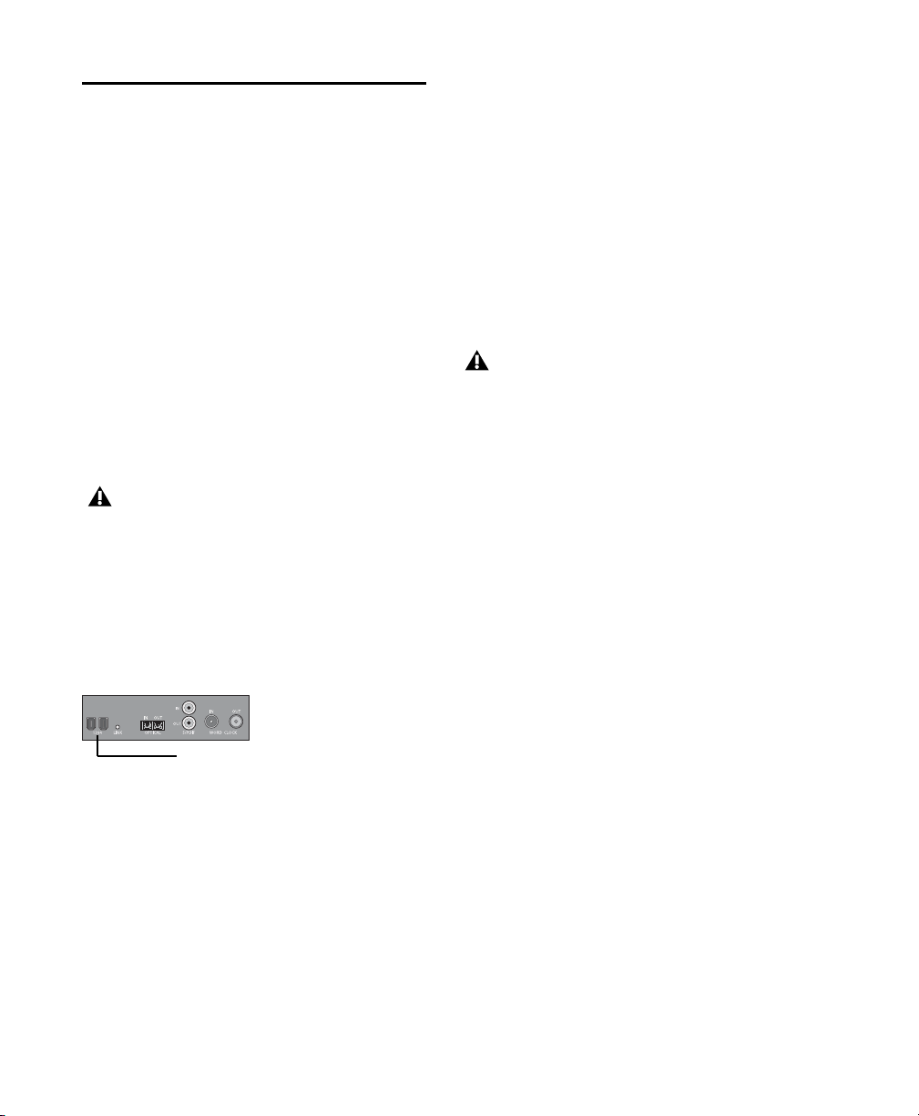
Connecting Your 003 Series
FireWire ports
Device to Your Computer
After installing Pro Tools LE software, connect
your 003 series device to your computer before
launching Pro Tools LE.
To connect your 003 series device to your
computer:
1 If your computer is on, power it down.
2 Plug the 003 series device into a standard AC
receptacle, using the AC power cable included
with the unit. AC power is required to operate
your 003 series device.
3 Locate the FireWire cable that came with your
unit.
Be sure to note the orientation of the
FireWire cable connector when you insert it
in your 003 series device. It is possible to
damage the FireWire port if you force the
connector in upside down.
5 Do one of the following, depending on your
system configuration:
• Plug the other end of the FireWire cable
into an available FireWire port on your
computer.
– or –
• If your computer has only one FireWire
port, plug the other end of the FireWire cable into an available FireWire port on a
FireWire hard drive connected to your
computer.
Connecting your 003 series device to your
computer through a FireWire hard drive does
not support maximum track count. To
achieve the maximum track count, purchase
a PCI/PCMCIA/ExpressCard to increase the
number of FireWire ports on your computer.
For information on supported PCI/PCMCIA/ExpressCard FireWire options, visit the
Digidesign website (www.digidesign.com).
4 Plug one end of the FireWire cable into one of
the ports marked “1394” on the back panel of
your 003 series device. Either port will work.
003 series FireWire ports (back panel)
003 Series Getting Started Guide18
Page 29

Launching Pro Tools LE
When launching Pro Tools LE the first time, you
are prompted to enter an authorization code to
validate your software.
Updating 003 Series Firmware
When you launch Pro Tools software, it automatically checks the version of the unit’s firmware and prompts you to update it if a newer
version is available.
To authorize Pro Tools LE software:
1 Make sure your 003 series device is connected
to your computer and powered on.
2 Do one of the following:
• Click the Pro Tools LE icon in the Dock.
– or –
• Locate and double-click the Pro Tools LE
application on your hard drive.
If you get a warning dialog about updating
the firmware for your hardware, follow the
on-screen instructions to perform the
firmware update. See “Updating 003 Series
Firmware” on page 19.
3 Enter the authorization code in the dialog
(making sure to type it exactly as printed, and
observing any spaces and capitalization), then
click Validate.
Your authorization code is located on the inside
cover of this guide.
If you update your unit’s firmware, let the update complete before disconnecting or turning
off your system.
When a firmware update completes, Pro Tools
quits, and you must relaunch Pro Tools.
If during the update process you get a message
that Pro Tools cannot communicate with your
003 series device, wait up to 30 seconds for the
message to close. If the message does not go
away, power off 003 series device and then
power it on again.
Connecting FireWire Drives
Connect FireWire hard drives directly to a
FireWire port on your computer.
Do not connect a FireWire hard drive to the
second FireWire port on the back panel of
your 003 series device.
The FireWire ports on 003 series devices do not
pass data when they are powered off. If you
daisy-chain FireWire devices from your computer, it is best to connect FireWire hard drives
directly to your computer and not to the 003 series device. This will prevent hard drive errors
and data loss in case the 003 series device is powered off.
To yield higher performance from audio
drives, enable journaling. See “Enabling
Journaling for Audio Drives” on page 34.
Chapter 4: Installing Pro Tools on Mac 19
Page 30

To connect a FireWire hard drive, do one of the
following:
If your computer has more than one FireWire
port, connect the FireWire hard drive to one
FireWire port on the computer, and connect
your 003 series device to another FireWire port
on the computer.
– or –
If your computer has only one FireWire port,
connect the FireWire hard drive directly to your
computer and then connect your 003 series device to an available FireWire port on the drive.
Connecting your 003 series device to your
computer through a FireWire hard drive does
not support maximum track count. To
achieve the maximum track count, purchase
a PCI/PCMCIA/ExpressCard to increase the
number of FireWire ports on your computer.
For information on supported PCI/PCMCIA/ExpressCard FireWire options, visit the
Digidesign website (www.digidesign.com).
Connecting Other FireWire Devices to 003 Series Interfaces
The second FireWire port on your 003 series interface is available for daisy-chaining FireWire
devices such as digital cameras or digital video
recorders. Even when it is powered off, 003 series interfaces supply power from the computer
through its FireWire ports, letting you recharge
batteries in connected FireWire devices.
Uninstalling Pro Tools
If you need to uninstall Pro Tools software from
your computer, use the Uninstaller application.
To uninstall Pro Tools from your computer:
1 Make sure you are logged in as an Administra-
tor for the account where Pro Tools is installed.
For details on Administrator privileges in
Mac OS X, see your Apple OS X documentation.
2 Go to Applications/Digidesign/Pro Tools/
Pro Tools Utilities and double-click the
“Uninstall Pro Tools” file.
3 Click Continue to proceed with the uninstall.
4 Choose the type of uninstall you want to per-
form:
Safe Uninstall Leaves certain plug-ins and system files needed for compatibility with some
Avid products. Use Safe Uninstall if you are using
an Avid application or preparing to update to a
.cs release.
Clean Uninstall Removes all Pro Tools files, including system files, Digidesign plug-ins, and
MIDI patch names. Use Clean Uninstall whenever
you are preparing to upgrade, or to troubleshoot
from a clean system.
5 Click Uninstall.
6 Enter your Administrator password and click
OK.
7 Click Finish to close the Installer window.
003 Series Getting Started Guide20
Page 31

chapter 5
Configuring Your Pro Tools System
After you have connected your system and installed Pro Tools software, you are ready to start
up and configure your Pro Tools system.
Starting Up or Shutting Down Your System
To ensure that the components of your
Pro Tools system communicate properly with
each other, you need to start them in a particular order.
Start up your Pro Tools system in this order:
1 Lower the volume of all output devices in your
system.
2 Turn on any external hard drives. Wait ap-
proximately ten seconds for them to spin up to
speed.
3 Turn on any control surfaces (such as Com-
mand|8).
4 Turn on any MIDI interfaces, MIDI devices, or
synchronization peripherals.
Shut down your Pro Tools system in this order:
1 Quit Pro Tools and any other running applica-
tions.
To quit Pro Tools, choose File > Exit
(Windows) or Pro Tools > Quit (Mac).
2 Turn off or lower the volume of all output de-
vices in your system.
3 Turn off your computer.
4 Turn off the 003 series device.
5 Turn off any MIDI interfaces, MIDI devices, or
synchronization peripherals.
6 Turn off any control surfaces.
7 Turn off any external hard drives.
5 Turn on the 003 series device.
6 Turn on your computer.
7 Launch Pro Tools or any third-party audio or
MIDI applications.
Chapter 5: Configuring Your Pro Tools System 21
Page 32

Configuring Pro Tools LE Software
Pro Tools System Settings
In the Playback Engine dialog, Pro Tools LE lets
you adjust the performance of your system by
changing system settings that affect its capacity
for processing, playback, and recording
In most cases, the default settings for your system provide optimum performance, but you
may want to adjust them to accommodate large
or processing-intensive Pro Tools sessions.
Playback Engine dialog (without Structure plug-in
installed)
Playback Engine dialog (with Structure installed)
Hardware Buffer Size
The Hardware Buffer Size (H/W Buffer Size) controls the size of the buffer used to handle host
processing tasks such as Real-Time AudioSuite
(RTAS) plug-ins. The H/W Buffer setting can also
be used to manage monitoring latency.
Lower Hardware Buffer Size settings reduce
monitoring latency, and are useful when you are
recording live input.
Higher Hardware Buffer Size settings allow for
more audio processing and effects, and are useful when you are mixing and using more RTAS
plug-ins.
In addition to causing slower screen response
and monitoring latency, higher Hardware
Buffer Size settings can increase the latency
caused by RTAS plug-ins, and affect the
accuracy of plug-in automation, mute data,
and MIDI track timing.
003 Series Getting Started Guide22
Page 33

To change the Hardware Buffer Size:
1 Choose Setup > Playback Engine.
2 From the H/W Buffer Size pop-up menu, select
the audio buffer size, in samples.
3 Click OK.
RTAS Processors
The RTAS Processors setting determines the
number of processors in your computer allocated for RTAS (Real-Time AudioSuite) plug-in
processing.
With multiprocessor computers, this setting lets
you manage multi-processor support for RTAS
processing. With multiple processor computers
that support Hyper-Threading (and have it enabled), you must disable Hyper-Threading for
this setting to become available. See your computer’s documentation for steps on how to enter
the computer’s BIOS and disable Hyper-Threading.
Used in combination with the CPU Usage Limit
setting, the RTAS Processors setting lets you control the way RTAS processing and other
Pro Tools tasks are carried out by the system. For
example:
• For sessions with large numbers of RTAS plugins, you can allocate 2 or more processors to
RTAS processing and set a high CPU Usage
Limit.
• For sessions with few RTAS plug-ins, you can
allocate fewer processors to RTAS and set a low
CPU Usage Limit to leave more CPU resources
available for automation accuracy, screen response, and video.
• Depending on the importance of video and
overall screen response, and on the density of
automation being employed, try different
combinations of RTAS Processing and CPU
Usage Limit settings to achieve the best results. For example, to improve screen response in a medium-sized session using a
moderate number of RTAS plug-ins, try reducing the number of RTAS plug-ins, but keep the
CPU Usage Limit set to its maximum on a single processor system.
To set the number of RTAS Processors:
1 Choose Setup > Playback Engine.
2 From the RTAS Processors pop-up menu, select
the number of available processors you want to
allocate for RTAS plug-in processing. The number of processors available varies depending on
how many processors are available on your computer:
• Choose 1 Processor to limit RTAS processing to one CPU in the system.
• Choose 2 Processors to enable load balancing across two available processors.
• On systems running four or more processors, choose the desired number of RTAS
processors as needed.
3 Click OK.
Chapter 5: Configuring Your Pro Tools System 23
Page 34

CPU Usage Limit
RTAS Engine (RTAS Error Suppression)
The CPU Usage Limit controls the percentage of
CPU resources allocated to Pro Tools host processing tasks. Used in combination with the
RTAS Processors setting, the CPU Usage Limit
setting lets you control the way Pro Tools tasks
are carried out by the system.
Lower CPU Usage Limit settings limit the ef-
fect of Pro Tools processing on other CPU-intensive tasks, such as screen redraws, and are useful
when you are experiencing slow system response, or when running other applications at
the same time as Pro Tools.
Higher CPU Usage Limit settings allocate
more processing power to Pro Tools, and are useful for playing back large sessions or using more
real-time plug-ins.
The maximum available CPU Usage Limit depends on the number of processors in your computer and on the number of processors you specify for RTAS processing. This value can range
from 85 percent for single-processor computers
to 99 percent for multi-processor computers.
Increasing the CPU Usage Limit may slow
down screen response on slower computers.
To change the CPU Usage Limit:
1 Choose Setup > Playback Engine.
2 From the CPU Usage Limit pop-up menu, se-
lect the percentage of CPU processing you want
to allocate to Pro Tools.
3 Click OK.
The RTAS Engine options determine RTAS error
reporting during playback and recording. This is
especially useful when working with instrument
plug-ins.
You should only enable RTAS error suppression
if you are experiencing frequent RTAS errors
that are interrupting your creative workflow.
When RTAS error suppression is enabled, you
can experience a degradation of audio quality.
However, this may be acceptable in order to
avoid interrupting playback and recording
when working with instrument plug-ins. Be sure
to disable RTAS error suppression when you
need to ensure the highest possible audio quality, such as for a final mix.
There are two RTAS Engine options:
Ignore Errors During Playback/Record When enabled, Pro Tools continues to play and record
even if the RTAS processing requirements exceed the selected CPU Usage Limit. This can result in pops and clicks in the audio, as well as additional latency, but does not stop the transport.
This will only suppress errors in the RTAS engine. Disk-based errors (if any) will continue to
stop the transport.
Minimize Additional I/O Latency (Mac OS X
Only) When enabled, any additional latency due
to suppressing RTAS errors during playback and
record is minimized to 128 samples. Suppressing
RTAS errors requires at least 128 samples of additional buffering on some systems. If this option is disabled, the buffer is half the H/W Buffer
Size, or at least 128 samples (which ever is
greater). If you are on a slower computer, you
may not want to enable this option since doing
so can adversely affect performance.
003 Series Getting Started Guide24
Page 35

The Minimize Additional I/O Latency option is
only available if the Ignore Errors During Playback/Record option is enabled.
To enable RTAS error suppression:
1 Choose Setup > Playback Engine.
2 Select Ignore Errors During Playback/Record.
3 On Mac OS X, you can also select Minimize Ad-
ditional I/O Latency.
4 Click OK.
DAE Playback Buffer Size
The DAE Playback Buffer Size determines the
amount of memory DAE allocates for disk buffers. The buffer size is shown in milliseconds,
which indicates the amount of audio buffered
when the system reads from disk.
Using a larger DAE Playback Buffer Size
leaves less system memory for other tasks.
The default setting of 1500 msec (Level 2) is
recommended unless you are encountering
-9073 (“Disk too slow or fragmented”)
errors.
To change the DAE Playback Buffer Size:
1 Choose Setup > Playback Engine.
2 From the DAE Playback Buffer pop-up menu,
select a buffer size. Memory requirements for
each setting are shown at the bottom of the
Playback Engine dialog.
3 Click OK.
If Pro Tools needs more system memory for the
DAE Playback Buffer, it will prompt you to restart your computer.
The optimum DAE Playback Buffer Size for most
disk operations is 1500 msec (Level 2).
• DAE Playback Buffer Size settings lower than
1500 msec (Level 2) may improve playback and
recording initiation speed. However, a lower setting may make it difficult to play or record
tracks reliably with sessions containing a large
number of tracks or a high density of edits, or
with systems that have slower or heavily fragmented hard drives.
• DAE Playback Buffer Size settings higher than
1500 msec (Level 2) allow higher track count,
higher density of edits in a session, or the use of
slower hard drives. However, a higher setting
may increase the time lag when starting playback or recording, or cause a longer audible time
lag while editing during playback.
Cache Size
The Cache Size determines the amount of memory DAE allocates to pre-buffer audio for playback and looping when using Elastic Audio.
The optimum Cache Size for most sessions is
Normal.
• A Cache Size setting of Minimum reduces the
amount of system memory used for disk operations and frees up memory for other system
tasks. However, performance when using Elastic
Audio features may decrease.
• A Cache Size of Large improves performance
when using Elastic Audio features, but it also decreases the amount of memory available for
other system tasks, such as RTAS processing.
Using a larger Cache Size leaves less system
memory for other tasks. The default setting
of Normal is recommended unless you are
encountering -9500 (“Cache too small”)
errors.
Chapter 5: Configuring Your Pro Tools System 25
Page 36

To change the Cache Size:
1 Choose Setup > Playback Engine.
Plug-in Streaming Buffer Size
(Structure Plug-in Only)
2 From the Cache Size pop-up menu, select a
disk cache size.
3 Click OK.
System Memory Allocation
When you start your computer, Pro Tools automatically reserves a portion of system memory
for the DAE Playback Buffer. This reserved memory is unavailable to other applications, even if
Pro Tools is not running.
You can set Pro Tools to reserve only the minimum amount of required memory, so that more
system memory is available to other applications.
To minimize system memory allocation:
1 Choose Setup > Playback Engine.
2 Select the “Minimize System Memory Allocation”
option.
3 Click OK.
4 Restart your computer.
This setting appears in the Playback Engine dialog only if the Structure sampler instrument
plug-in is installed on your system. The Plug-in
Streaming Buffer Size determines the amount of
memory DAE allocates for streaming playback
from disk with the Structure plug-in. This setting only affects playback if disk streaming is activated in Structure’s plug-in controls (see the
Structure Plug-in Guide for more information).
The optimum Plug-in Streaming Buffer Size for
most sessions is 250 ms (Level 2).
• Plug-in Streaming Buffer Size settings lower
than 250 msec (Level 2) reduce the amount of
system memory used for sample playback and
frees up memory for other system tasks. However, audio quality of sample playback may decrease.
• Plug-in Streaming Buffer Size settings higher
than 250 msec (Level 2) improve the audio quality of sample playback, but they also decrease
the amount of memory available for other system tasks, such as RTAS processing.
Using a larger Plug-in Streaming Buffer Size
leaves less system memory for other tasks.
The default setting of 250 ms (Level 2) is
recommended unless you are experiencing
problems with the audio quality of sample
playback.
To change the Plug-in Streaming Buffer Size:
1 Choose Setup > Playback Engine.
2 From the Plug-in Streaming Buffer Size pop-up
menu, select a buffer size.
3 Click OK.
003 Series Getting Started Guide26
Page 37

Optimizing the Plug-in Streaming Buffer
Size
(Structure Plug-in Only)
This option appears in the Playback Engine dialog only if the Structure sampler instrument
plug-in is installed on your system. This option
is useful when you are playing samples from the
same drive that contains audio for the current
session. When this option is selected, Pro Tools
automatically optimizes the size of the Plug-in
Streaming Buffer to facilitate disk access from
both Pro Tools and Structure. The Plug-in
Streaming Buffer Size pop-up menu is unavailable when this option is selected.
To change the default Sample Rate:
1 Choose Setup > Hardware.
Hardware Setup dialog
2 Select the sample rate from the Sample Rate
pop-up menu.
3 Click OK.
To set Pro Tools to optimize the Plug-in Streaming
Buffer Size:
1 Choose Setup > Playback Engine.
2 Select the “Optimize for Streaming Content” op-
tion.
3 Click OK.
Pro Tools Hardware Settings
In the Hardware Settings dialog, Pro Tools lets
you set the default sample rate and clock source
for your system, and configure the digital inputs
on the 003 series device.
Default Sample Rate
The Sample Rate setting appears as the default
sample rate when you create a new session. (This
setting is available in the Hardware Setup dialog
only when no session is open.)
You can change the sample rate when
creating a new Pro Tools session by selecting
a different sample rate in the New Session
dialog. See
details.
the Pro Tools Reference Guide for
Clock Source
The Pro Tools Hardware Setup dialog lets you select the Clock Source for the system.
Internal If you are recording an analog signal directly into Pro Tools (or using an external analog or digital device for effects), you will usually
use the Internal setting.
External If you are transferring material into
Pro Tools from an external digital device, or if
you utilize a common house clock signal, you
will synchronize Pro Tools to the digital device
or common signal. The external clock source
corresponds to the connector on the back of the
003 series device that is receiving your clock signal: S/PDIF (RCA), Optical, or Word Clock. If
you are using an optical device, you also need to
set the Optical Format (ADAT or S/PDIF).
You can use only one pair of S/PDIF inputs
(either RCA or Optical) at a time. At
96 kHz, it is recommended that you use the
S/PDIF (RCA) port.
Note that S/PDIF (RCA) output is still
available when S/PDIF Optical is selected.
Chapter 5: Configuring Your Pro Tools System 27
Page 38

To select the Clock Source:
1 Choose Setup > Hardware.
2 Choose the clock source from the Clock
Source pop-up menu.
Optical Format
The Optical port can be set for eight channels of
ADAT Optical I/O (supporting up to 48 kHz) or
two channels of S/PDIF Optical I/O. The Optical
Format ADAT option is replaced by None for session rates 88.2 kHz and 96 kHz.
If you are using an optical device for recording,
you need to set the Optical Format.
To select the digital format of the Optical I/O port:
1 Choose Setup > Hardware.
Hardware Setup dialog
Your digital input device must be connected
and turned on for Pro Tools to synchronize
to it. If your input device is not turned on,
leave the Clock Source set to Internal.
Only one S/PDIF input pair can be used at a
time. When you select S/PDIF (RCA) as the
Clock Source, the Optical Format setting
will switch to ADAT (for sample rates
44.1 kHz and 48 kHz), or to None (for sample rates 88.2 kHz and 96 kHz).
Conversely, when you select S/PDIF as the
Optical Format, the Clock Source setting
will switch to Internal if it was previously
set to S/PDIF (RCA).
3 Click OK.
2 In the Optical Format section, do one of the
following:
• Select ADAT if your optical device is using
the ADAT format.
– or –
• Select S/PDIF if yo ur opti ca l s ourc e dev ic e is
using the S/PDIF format.
Only one S/PDIF input pair can be used at a
time. When you select S/PDIF as the
Optical Format, the Clock Source setting
will switch to internal if it was previously
set to S/PDIF (RCA).
Conversely, when you select S/PDIF (RCA)
as the Clock Source, the Optical Format setting will switch to ADAT (for sample rates
44.1 kHz and 48 kHz), or to None (for sample rates 88.2 kHz and 96 kHz).
3 Click OK.
003 Series Getting Started Guide28
Page 39
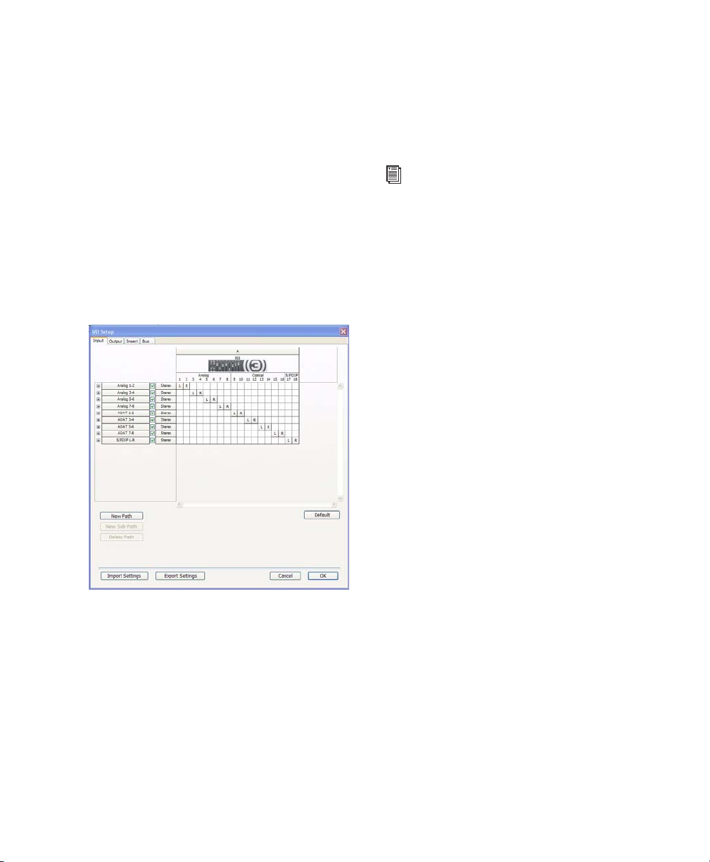
Configuring I/O Setup
Using the I/O Setup dialog, you can label
Pro Tools LE input, output, insert, and bus signal
paths. The I/O Setup dialog provides a graphical
representation of the inputs, outputs, and signal
routing of the 003 series device.
Pro Tools LE has default I/O Setup settings that
will get you started. Use the I/O Setup dialog
only if you want to rename the default I/O
paths.
3 To change the name of a path or subpath, dou-
ble-click directly on the Path Name, type a new
name for the path, and press Enter (Windows) or
Return (Mac).
4 Click OK.
See the Pro Tools Reference Guide (or choose
Help > Pro Tools Reference Guide) for more
information on renaming I/O paths.
Configuring MIDI Setup
To rename I/O paths in I/O Setup:
1 Choose Setup > I/O.
I/O Setup dialog, Input tab
2 Click the Input, Output, Insert, or Bus tab to
display the corresponding paths.
If you plan to use any MIDI devices with Pro Tools,
do one of the following:
On Windows, configure your MIDI setup with
MIDI Studio Setup. See Appendix A, “Configuring MIDI Studio Setup (Windows Only)” for details.
– or –
On Mac, configure your MIDI setup with Au-
dio MIDI Setup. See Appendix B, “Configuring
AMS (Mac OS X Only)” for details.
Backing Up Your System Configuration
After configuring your system and Pro Tools,
you should save an image of your system drive
using a backup utility such as Norton Ghost
(Windows) or Bombich Carbon Copy Cloner
(Mac). By doing this, you can quickly restore
your system configuration and settings if you
encounter any problems.
Chapter 5: Configuring Your Pro Tools System 29
Page 40

Optimizing a Windows Vista System for Pro Tools
Disabling Screen Saver
To avoid errors during recording and playback
of Pro Tools sessions, you must set your Windows Vista screen saver to “None.”
To set your Windows Vista screen saver to “None”:
1 Right-click on the desktop.
2 Choose Personalize.
3 Click Screen Save.
4 Set the Screen saver to None.
Required Optimizations
To ensure optimum performance with
Pro Tools LE, configure the following settings
before using Pro Tools hardware and software.
When you are finished changing Windows
system settings, restart your computer.
Enabling DMA
Enabling your computer's DMA (Direct Memory
Access) frees up CPU bandwidth so your computer can do other Pro Tools tasks.
In most cases the DMA option will already be set
correctly, as Windows detects and activates
DMA mode by default.
5 Click Apply.
Optimizing a Windows XP System for Pro Tools
You can configure your Windows system settings to ensure optimum performance with
Pro Tools.
To optimize a Mac system for Pro Tools, see
“Optimizing a Mac System for Pro Tools”
on page 33.
Before configuring your computer, make sure
you are logged in as an Administrator for the account where you want to install Pro Tools. For
details on Administrator privileges, see your
Windows documentation.
To enable DMA for any IDE hard drives:
1 Choose Start > Control Panel.
2 Double-click System.
3 Click the Hardware tab.
4 Under Device Manager, choose Device Man-
ager.
5 In the Device Manager window, double-click
IDE ATA/ATAPI controllers, then double-click the
Primary IDE Channel for your IDE hard drive.
6 Click the Advanced Settings tab.
7 For each device, set the Transfer Mode to “DMA
if available,” and click OK.
8 Repeat the above steps for any additional IDE
Channels.
9 Close the Device Manager window and then
the System Properties window.
003 Series Getting Started Guide30
Page 41

Disabling System Standby and Power
Management
When using Pro Tools, the Windows System
Standby power scheme must be set to Always On.
This helps prevent long record or playback
passes from stopping due to system resources
powering down.
To configure Windows Power Management:
1 Choose Start > Control Panel.
2 Double-click Power Options.
3 Click the Power Schemes tab.
Disabling ClearType Font Smoothing
When using Pro Tools, the Effects “Clear Type”
setting must be disabled.
To disable ClearType font smoothing:
1 Choose Start > Control Panel.
2 Double-click Display.
3 Click the Appearance tab.
4 Click Effects.
5 Deselect “Use the following method to smooth
edges of screen fonts.”
4 From the Power Schemes pop-up menu, select
Always On.
5 Click OK.
This sets System Standby, System Hibernate,
and “Turn off hard disks” to Never.
On AMD processors, be sure to check and
disable Cool N’Quiet in the System BIOS (in
the Cool & Quiet Configuration section). See
the manufacturer’s documentation for instructions on disabling this power option, if
necessary.
6 Click OK to save your settings and close the Ef-
fects dialog.
7 Click OK.
8 Restart the computer.
Chapter 5: Configuring Your Pro Tools System 31
Page 42

Recommended Optimizations
Pro Tools can also be affected by other software
and hardware drivers installed on your computer. For best possible performance, it is recommended (but not required) that you do the following:
• Avoid running any unneeded programs at
the same time as Pro Tools.
• Turn off any software utilities that run in
the background, such as Windows Messenger, calendars, and disk maintenance programs.
• Turn off any non-essential USB devices
while running Pro Tools.
• If your video display card supports it, enable Bus Mastering in the manufacturer’s
Control Panel. See the manufacturer’s instructions for details.
Optional Optimizations
The following system optimizations may help
Pro Tools perform better on some systems. It is
recommended that you only try these optimizations if necessary, as they may disable or adversely affect the functionality of other programs on your system.
To disable a network card:
1 Right-click My Computer and choose Manage.
2 Under System Tools, select Device Manager.
3 In the Device Manager window, double-click
Network adapters, then double-click the Network
Adapter card you want to disable.
4 Under the General tab, choose “Do not use this
device (disable)” from the Device Usage pop-up
menu, and click OK.
5 Close the Computer Management window.
Adjusting Processor Scheduling
To adjust Processor Scheduling performance:
1 Choose Start > Control Panel.
2 In Classic View, double-click System.
3 Click the Advanced tab.
4 Under the Performance section, click the Set-
tings button.
5 In the Performance Options window, click the
Advanced tab.
6 Under the Processor Scheduling section, select
the Background Services option.
Disabling Network Cards
If applicable, disable any networking cards
(other than a FireWire card, if you are using one
to connect your 003 series device or any
FireWire drives to your system).
003 Series Getting Started Guide32
7 Under the Memory Usage section, select the
System cache option.
8 Click OK to close the Performance Options
window.
9 Click OK to close the System Properties win-
dow.
10 Restart the computer for the changes to take
effect.
Page 43

Disabling System Startup Items
The fewer items in use by your computer, the
more resources are available for Pro Tools. Some
startup applications may be consuming unnecessary CPU resources, and can be turned off.
If you disable any of the following startup items,
do so carefully:
• Portable media serial number (required for
some applications that utilize a copy protection key)
• The Plug and Play service
•Event log
• Cryptographic services
To Disable System Startup Items:
1 From the Start menu, choose Run.
2 Type “msconfig” and click OK. The System
Configuration Utility opens.
3 Under the General tab, choose Selective Star-
tup.
4 Deselect Load Startup Items and click OK.
5 Click Restart to restart the computer.
6 After restarting, the computer displays a Sys-
tem Configuration message. Check to see if
Pro Tools performance has increased before you
deselect the “Don't show this message again”
option. If performance has not changed, run
“msconfig” and return your computer Startup
Selection back to Normal Startup - load all device
drives and services. Alternatively, try disabling
Startup items and non-essential processes individually.
Optimizing a Mac System for Pro Tools
To optimize a Windows Vista system for
Pro Tools, see “Optimizing a Windows
Vista System for Pro Tools” on page 30.
To optimize a Windows XP system for
Pro Tools, see “Optimizing a Windows XP
System for Pro Tools” on page 30.
To ensure optimum performance with
Pro Tools LE, configure your computer before
using Pro Tools software.
Before configuring your computer, make sure
you are logged in as an Administrator for the account where you want to install Pro Tools. For
details on Administrator privileges in Mac OS X,
see your Apple OS X documentation.
Do not use the Mac OS X automatic
Software Update feature, as it may upgrade
your system to a version of Mac OS that has
not yet been qualified for Pro Tools. For
details on qualified versions of Mac OS, see
the latest compatibility information on the
Digidesign website (www.digidesign.com).
Turning Off Software Update
To turn off the Software Update feature:
1 Choose System Preferences from the Apple
menu and click Software Update.
2 Click the Software Update tab.
3 Deselect Check for Updates.
Chapter 5: Configuring Your Pro Tools System 33
Page 44

Turning Off Energy Saver
Disabling the Spotlight Shortcuts
To turn off the Energy Saver feature:
1 Choose System Preferences from the Apple
menu and click Energy Saver.
2 Click the Sleep tab and do the following:
• Set the computer sleep setting to Never.
• Set the display sleep setting to Never.
• Deselect “Put the hard disk(s) to sleep when
possible” option.
Setting Processor Performance
(Mac G5 Computers and G4 Powerbooks Only)
To set the Processor Performance:
1 Choose System Preferences from the Apple
menu and click Energy Saver.
2 Click the Options tab and set Processor Perfor-
mance to Highest.
Disabling Spotlight Indexing
The Mac OS X Spotlight feature indexes files and
folders in the background, affecting system performance. It is recommended that you disable
Spotlight indexing before using Pro Tools.
Disabling Spotlight indexing will cause the
Find function in Mac OS X to no longer
work. You will no longer be able to search
for files on drives set to private.
To disable Spotlight indexing:
1 Choose System Preferences from the Apple
menu and click Spotlight.
2 In the Spotlight window, click the Privacy tab.
3 To prevent indexing of a drive, drag its icon
from the desktop into the list.
The Mac OS X Spotlight feature uses the same
key commands Pro Tools uses to start recording
(Command+Spacebar), and to record online
(Command+Option+Spacebar). If you want to
retain use of these key commands in Pro Tools,
these shortcuts must be disabled.
To disable the Spotlight keyboard shortcut:
1 Choose System Preferences from the Apple
menu and click Spotlight.
2 Deselect “Spotlight menu keyboard shortcut”
and “Spotlight window keyboard shortcut.”
Disabling the Dashboard Shortcut
The Mac OS X Dashboard feature uses the same
key command Pro Tools uses to start recording
(F12). If you want to retain use of this key command in Pro Tools, this shortcut must be disabled.
To disable the Dashboard keyboard shortcut:
1 Choose System Preferences from the Apple
menu and click Dashboard and Exposé.
2 Set the Dashboard keyboard shortcut to “–” to
disable the shortcut.
Enabling Journaling for Audio Drives
To yield higher performance from audio drives,
enable journaling.
To enable journaling:
1 Launch the Disk Utility application, located in
Applications/Utilities.
2 Select the volume in the left column of the
Disk Utility window.
3 Click Enable Journaling in the toolbar.
003 Series Getting Started Guide34
Page 45

chapter 6
003 Top Panel
003 Operating Modes
003 can be in any of five states when it is on:
• Standby mode
•ProTools mode
•MIDI mode
• Third-Party Software mode
• Utility mode
Standby Mode
003 is in this mode when you first power on the
unit, waiting for you to launch Pro Tools (or another supported application).
In Standby mode, the unit displays “003 Offline” in the top row of the 003 display and the
Monitor Mute switch is enabled (lit).
In Standby mode, the Monitor section I/O ports
are available, without having to power on the
computer.
While in Standby mode, you can also switch to
MIDI mode to control external MIDI devices
(without having to power on the computer).
However, you cannot use 003 as a standalone
MIDI router; you must route MIDI through software.
Pro Tools Mode
003 is in this mode when the 003 unit is connected to a computer and Pro Tools LE software
is running.
If Pro Tools is running and no Pro Tools session
is open, the unit normally displays “Open or
create a new session.” When a session is being
launched, the display changes to “Loading a session.”
If no session is open and a Workspace
browser is open and being used for auditioning an audio file, the unit displays “Working.”
When a Pro Tools session is open, the unit mirrors the on-screen controls. 003 faders, transport
switches, rotary knobs, and switches control the
corresponding elements in Pro Tools. You can
also use 003 MIDI ports as you would those on a
standard MIDI interface.
In Pro Tools mode, the Monitor section and
MIDI I/O ports are available with a session open
or closed.
Chapter 6: 003 Top Panel 35
Page 46

To put 003 in Pro Tools mode:
1 Make sure the 003 unit is properly connected
to the computer and powered on.
To use a third-party software application with 003:
1 Make sure 003 is properly connected to the
computer and in Standby mode.
2 If Mute is disabled (unlit), enable Mute by
pressing the Monitor Mute switch so that it is lit.
3 Launch Pro Tools LE and open or create a
Pro Tools session.
MIDI Mode
003 is in this mode when either the MIDI Map A
or B switch is enabled (lit). In this mode, 003
functions as a MIDI control surface for external
devices and applications other than Pro Tools.
MIDI mode can be enabled in Pro Tools mode,
Third-Party Software mode, or Standby Mode.
For more information, see Chapter 14, “Using
MIDI Mode with 003.”
Third-Party Software Mode
003 is in this mode when the 003 unit is connected to a computer and you launch a
third-party audio application (such as iTunes or
Ableton Live), and then use 003 as your playback or recording device. You can also use 003
MIDI ports as you would those on a standard
MIDI interface.
In this mode, the unit displays “Working...” in
the top row of the LCD.
2 Configure your system and software for ASIO,
WaveDriver, or CoreAudio Driver.
See the Windows Audio Drivers Guide (for
ASIO and WaveDriver on Windows) or the
CoreAudio Drivers Guide (Mac).
3 If Mute is disabled (unlit), press the Monitor
Mute switch.
4 Launch your third-party audio application.
5 Disable the Monitor Mute switch (unlit).
6 Use monitor section controls and switches to
adjust audio input routing, monitor levels, and
headphone levels.
Playing Audio Audio from your third-party software application can be routed to 003’s outputs,
via the FireWire connection.
Recording Audio (ASIO Driver and CoreAudio
Driver Only) Audio from 003 inputs can be
routed to software inputs in your third-party
software applications, via the FireWire connection.
Refer to the documentation for your third-party
software for information on configuring inputs
and outputs.
On Windows, ASIO- and WaveDriver-compatible applications are supported. WaveDriver supports playback only. On Mac, CoreAudio Driver
applications are supported.
For more information on third-party audio
drivers, see the Windows Audio Drivers Guide
(for ASIO or WaveDriver on Windows) or the
CoreAudio Drivers Guide (Mac).
003 Series Getting Started Guide36
Utility Mode
003 is in this mode when the Utility switch is
enabled (flashing). In Utility mode, you can run
pre-programmed diagnostic tests of the 003 unit
(such as fader movement and LEDs). The Utility
switch is unavailable in Pro Tools mode.
See Appendix C, “Utility Mode (003 Only)”
for more information.
Page 47

003 Top Panel Overview
Fader section
Console/Channel
Modifiers section
Display Mode switch
Automation
section
View section
and Status LEDs
Display section
Transport and
Navigation controls
Monitor section
Miscellaneous
controls
Mic/DI
Input controls
Figure 1 identifies each of the main 003 control sections.
The 003 top panel is arranged in sections of controls with related functions. The Fader section includes standard channel strip controls, similar to any small-format mixer. The Console/Channel
View section provides powerful multi-state controls for viewing and controlling inserts, plug-ins and
sends in Pro Tools. The Transport and Navigation controls provide access to many of the on-screen
navigation features of Pro Tools.
Figure 1. Major sections of the 003 top panel
Chapter 6: 003 Top Panel 37
Page 48
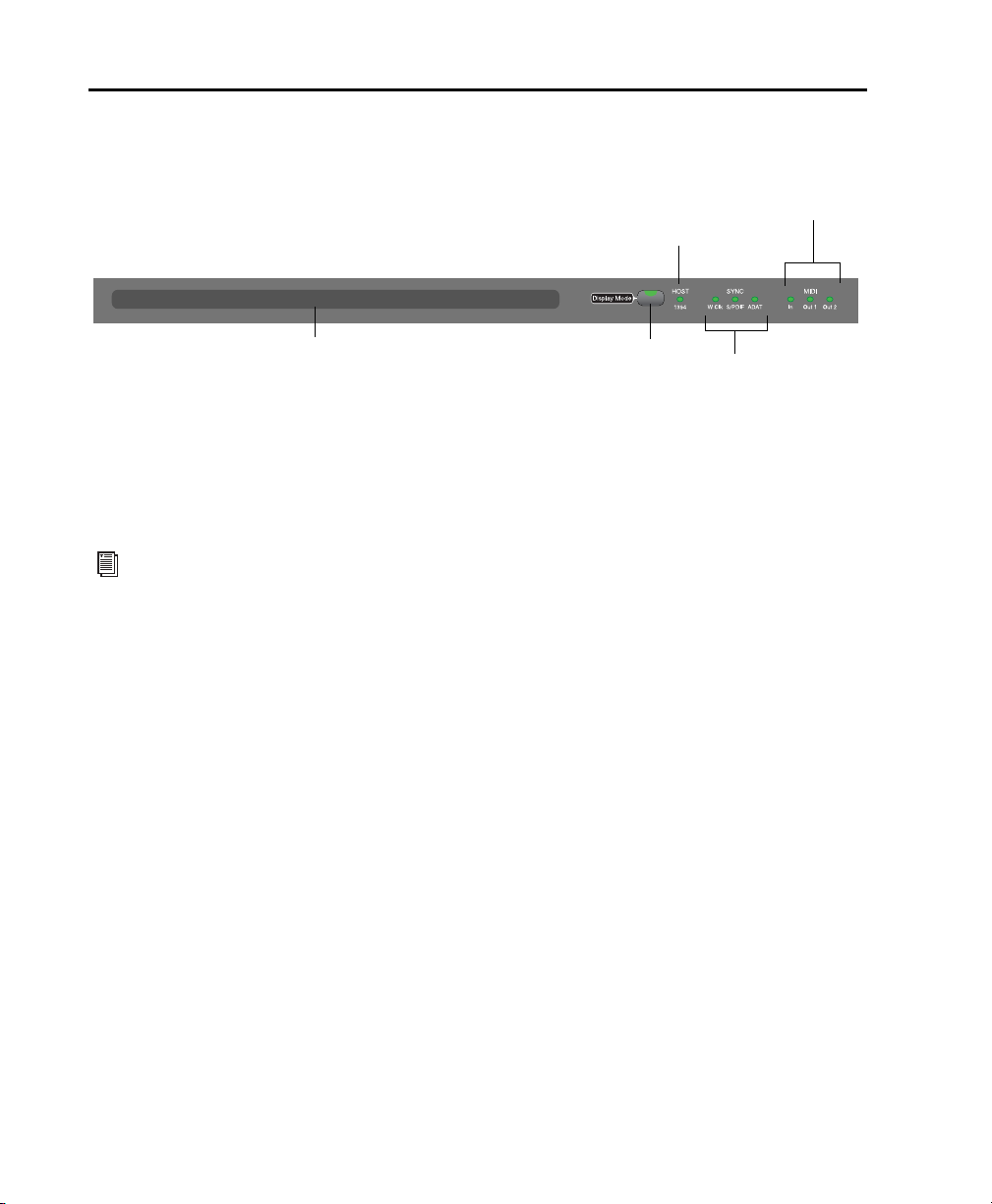
Display Section
Sync indicators
Host ‚”1394” status indicator
Display Mode switch
MIDI Data indicators
LCD display
The top portion of the 003 includes an LCD display, Display mode switch, and status indicators.
003 LCD, Display Mode switch, and status indicators
LCD Display
For all 003 operating modes, the LCD display
provides status information.
For information on the status information
displayed for each 003 operating mode, see
“003 Operating Modes” on page 35.
In Pro Tools mode, when a session is open, 003’s
LCD is a large, two-row display. The LCD display
dedicates two rows, each with up to six characters, to each channel strip.
In most views, the top row of the LCD shows the
the current view or mode status on the left side
and the session’s Main Counter on the right
side.
The bottom row of the LCD shows track, send,
and insert names, and pan position, send levels,
and plug-in control information, depending on
the current view, as selected by the Channel/Console switches.
The default display is the name of the displayed
element. Names of items with more than six
characters are abbreviated to six characters. Full
names of items with more than 6 characters can
be temporarily displayed in the LCD. See “Displaying Full Names of Tracks, Insert Parameters,
and Other Elements” on page 106.
When you move a fader or rotary encoder, the
LCD will temporarily display the value for that
control in the lower row of the LCD, then return
to the default display. Values can also be temporarily displayed without moving a control or set
to display always. See “Displaying Settings Instead of Track or Control Names” on page 106.
Additional LCD Naming Conventions in
Pro Tools Mode
When a send o r inse rt is muted, its names is capitalized in the LCD display.
When a track, send, or insert is inactive, “@” appears before its name in the LCD display.
003 Series Getting Started Guide38
Page 49

Display Mode Switch
Sync Indicators
This switch is used to change default LCD displays:
• Full names of items with more than 6 characters can be temporarily displayed in the LCD.
See “Displaying Full Names of Tracks, Insert
Parameters, and Other Elements” on
page 106.
• The lower row of the LCD shows track or control names by default. The display can be
changed to temporarily show settings by
pressing and holding the Display Mode
switch, or be reset to always show settings. See
“Displaying Settings Instead of Track or Control Names” on page 106.
The Display Mode switch flashes during a temporary display or when the LCD default has
been reset to always show settings.
Host (“1394”) Status Indicator
The Host status LED, marked “1394” below its
LED, indicates that communication has been established between the unit and Pro Tools LE
software (or another software application)
through FireWire.
The Sync LEDs indicate the current clock source.
When the current clock source is not established, the respective LED flashes.
If none of the Sync LEDs are lit, 003’s clock
source is set to internal.
There are three Sync LEDs:
W Clk (Word Clock) LED L i gh t s wh e n c lo c k in g t o
Word Clock.
S/PDIF LED Lights when clocking to the S/PDIF
on the RCA or Optical port.
ADAT LED Lights when clo cking to ADA T on the
Optical port.
MIDI Data Indicators
The MIDI Data LEDs indicate the presence of
MIDI data on the MIDI In, MIDI Out 1, or MIDI
Out 2 ports. Individual LEDs are provided for
each port. Active sensing is not indicated.
Chapter 6: 003 Top Panel 39
Page 50
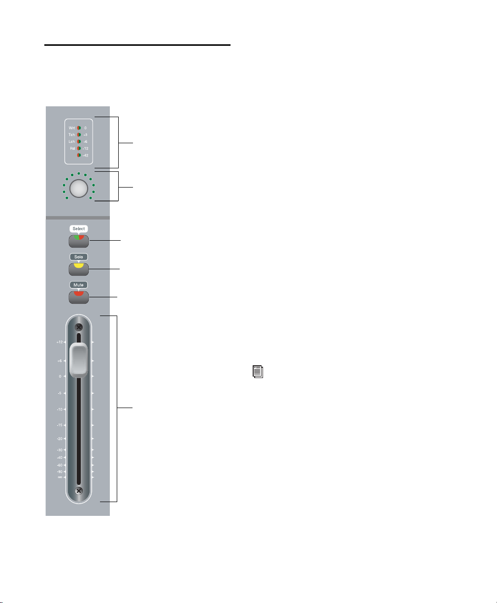
Fader Section
Channel Meter LEDs
Encoder/Meter LED ring
Channel Fader
Mute switch
Rotary Encoder and
Channel Select switch
Solo switch
The Fader section consists of eight channel
strips, each with identical controls.
Each fader has a motorized touch-sensitive
fader, solo and mute switches, a multi-state
Channel Select switch, a rotary encoder and its
LED ring, and meter LEDs. The LCD display dedicates two rows, each with up to six characters,
to each channel strip.
Channel Strip Controls
Channel Faders
Each channel has its own 100 mm, servo-driven,
touch-sensitive, motorized fader for controlling
levels of audio, Auxiliary Input, Master Fader,
MIDI, and Instrument tracks.
Flip Mode
In Flip mode (Flip switch lit), rotary encoder
controls are taken over by the faders, which
makes the rotary encoders available to control
another parameter. For example, in normal
Send View (Send switch lit), rotary encoders
control send level, while faders control output
gain. In Flip mode, faders (instead of rotary encoders) control the send level parameters and
rotary encoders control pan.
Channel strip in the Fader section
003 Series Getting Started Guide40
For more information, see “Using Flip
Mode” on page 114.
Page 51

Muting Fader Movement
Channel Select Switches
Because 003 faders are motorized, they move to
follow automation when playing back and recording (when the track is set to an automation
read or write mode, and not Off). During critical
listening passes, the sound of the fader motors
and their automated movements may be distracting. You can temporarily shut off (or mute)
motorized fader movement using the Fader
Mute switch.
When the Fader Mute switch is enabled (flashing), faders park and do not respond to touching
or movement. Previously recorded automation
continues to affect playback, while the faders are
disengaged from reading.
For more information, see “Muting Fader
Movement” on page 116.
Channel Solo/Mute Switches
Each channel has Solo and Mute switches, located above its fader. These switches let you solo
or mute the channel. The switches also show the
Pro Tools solo and mute status for each track.
When a track is soloed (Solo switch lit), the
Mute switches on other tracks in the session
flash. When a track is muted, its Mute switch is
lit continuously.
The Solo switch function follows the Pro Tools
Operation preference for latched operation. (See
the Pro Tools Reference Guide for details.)
Each channel has a Channel Select switch that
performs several functions, depending on the
view or mode, as follows.
Console View Depending on the Console View
(Pan, Send, or Insert), 003 can be used to do the
following:
• Select tracks or inserts on a particular channel for editing.
• Assign inputs, outputs, sends, or inserts
(plug-ins or hardware).
• Open track or send Output windows.
• Make track or send Outputs active or inactive.
• Select pre- or post-fader operation for
sends.
• Bypass plug-ins.
• Reset faders and other parameters to their
default settings.
For information on using Console View for
specific Pro Tools workflows, see
Chapter 13, “Pro Tools Mode with 003.”
Channel View Depending on the Channel View
(EQ, Dynamics, Insert, or Pan/Send), 003 can be
used to do the following:
• Display inserts or plug-ins on a channel.
• Select and edit individual send or insert settings as displayed across the LCD.
• Toggle switched plug-in controls (such as
bypass and Phase Invert).
• Cycle through plug-in windows.
For information on using Channel View for
specific Pro Tools workflows, see
Chapter 13, “Pro Tools Mode with 003.”
Chapter 6: 003 Top Panel 41
Page 52

Record Arming Mode When the Rec Arm switch
is enabled (flashing), the Channel Select switch
for a track enables or disables its Record Enable
button, plus acts as a record-enabled indicator.
When a track is record-enabled, its Channel Select switch flashes when the Transport is
stopped. When Pro Tools is recording, the
switch is lit continuously.
Tracks that are armed for recording will remain
armed after Rec Arming mode is disabled.
See “Rec Arm (Record Arm) Switch” on
page 43 for details on record-enabling
tracks.
Rotary Encoders
Each Channel has a rotary encoder. These knobs
control a variety of parameters, depending on
the view:
Console View The rotary encoders control pan,
send level, or insert settings, depending on
which Console View is enabled (Pan, Send, or
Insert).
Channel View The rotary encoders control
plug-in, pan/send, or insert settings, depending
on which Channel View is enabled (EQ, Dynamics, Insert, or Pan/Send).
Automation Mode The Automation Mode
switches (Write, Touch, Latch, Read, and Off) let
you use the Channel Select switches to set the
track’s Automation mode.
See “Automation Section” on page 52 for
more information.
Memory Location Mode In this mode (Memory
Location switch lit), Channel Select switches recall the Memory Location that corresponds to
their channel number. Additionally, the Memory Location window can be opened.
See “Working With Memory Locations” on
page 114 for more information.
Rotary Encoder LEDs
Each rotary encoder has a ring of 11 LEDs for indicating data values controlled by the encoder.
The style of display depends on the type of data.
For example, discrete or stepped information
such as pan position or frequency value is
shown by a single LED, while an expanding series of LEDs shows values such as send levels,
gain, or filter bandwidth. When you rotate the
encoder, its LEDs update.
In Pan View, the Meter switch sets what the
LEDs display (left pan, right pan, or no function
in Automation mode).
Channel Meter LEDs
Each channel includes a five-segment LED
meter, scaled at 0, –3, –6, –12, and –42 dBFS for
track level. The meters are also labeled to indicate the track’s current Automation mode: Wrt
(Write), Tch (Touch), Lch (Latch), or Rd (Read).
When the Meter switch is set to Left or Right,
these meters display track level. When the Meter
switch is set to Auto (Automation), the meter indicator corresponding to the track’s current Automation mode is lit.
003 Series Getting Started Guide42
Page 53

Meter Switch and LEDs
Meter switch and LEDs
Default and Input switches
Rec Arm switch
Mstr Faders switch
Flip switch
The Meter switch (located to the right of the encoder row) configures the display mode for
Channel Meter LEDs and the rotary encoder
LEDs.
Meter switch and LEDs
Global Fader Controls
Global Fader control switches
The following controls affect the assignment
and operation of all the faders:
The Meter switch also sets whether Left or Right
pan is controlled by a channel’s rotary encoder.
When you toggle through the three Meter
switch modes, the corresponding Meter switch
LED lights when its mode is enabled, as follows:
Left When enabled (LED lit), the Channel Meter
LEDs function as level meters, displaying mono
signals or the left channel of a stereo signal. Rotary encoder LEDs indicate the left pan position
(available on stereo channels or sends). Additionally, the rotary encoder can be used to adjust the left pan position on stereo channels or
sends.
Right When enabled (LED lit), the Channel
Meter LEDs function as level meters, displaying
the right channel of a stereo signal. Rotary encoder LEDs indicate the right pan position
(available on stereo channels or sends). Additionally, the rotary encoder can be used to adjust the right pan position on stereo channels or
sends.
Auto (Automation) When enabled (LED lit), the
Channel Meter LEDs display the Automation
mode for their channel. When the Auto switch
is enabled, the rotary encoders do not function.
Rec Arm (Record Arm) Switch
When the Rec Arm switch is enabled (flashing),
003 is in Record Arming mode. In this mode,
channels can be armed (record-enabled) or disarmed for recording by pressing their Channel
Select switch.
For information on how to record arm
tracks with 003, see “Recording” on
page 112.
In this mode, the top row of the LCD shows
“Record Arm” and the lower row of the LCD
shows track names. Additionally, volume fader
updates will not be reflected in the LCD, panning cannot be adjusted with rotary encoders,
and the Display mode cannot be changed.
In Record Arming mode, the Channel Select
switches act as record-enable switches and indicators. When a channel is record-enabled and
the transport is stopped (or playing back without recording), its Channel Select switch flashes.
When Pro Tools is recording, it is lit continuously.
Tracks that are armed for recording will remain
armed after Rec Arming mode is disabled.
Chapter 6: 003 Top Panel 43
Page 54

Mstr Faders (Master Faders) Switch
Default Switch
When enabled (flashing), the Master Faders
switch arranges all Master Fader tracks in the
current session on the right-hand side of the
control surface. Pressing this switch a second
time returns the control surface to the previous
view.
In Pan View, the Master Fader levels are displayed in the LCD.
Fader Flip Switch
When enabled (flashing), the Flip switch invokes Flip mode. Flip mode transfers control assignments from the rotary encoders to the corresponding channel faders, allowing you to use
the touch-sensitive faders to edit and automate
send and plug-in values. Additonally, in certain
views, the rotary encoders are available to control another parameter.
Flip mode is not available in Pan View.
See “Using Flip Mode” on page 114 for
more information.
The Default switch is used in conjunction with a
Channel Select switch to reset a fader (or
fader-mapped plug-in parameter) to its default
setting. For example, you can reset a channel
volume fader to its default level of 0.0 dB.
See “Setting Track Controls to Defaults” on
page 113 for more information.
Input Switch
The Input switch toggles Auto Input and Input
Only Monitor mode for record-enabled tracks.
See the Pro Tools Reference Guide for more
information about Pro Tools input monitoring modes.
003 Series Getting Started Guide44
Page 55
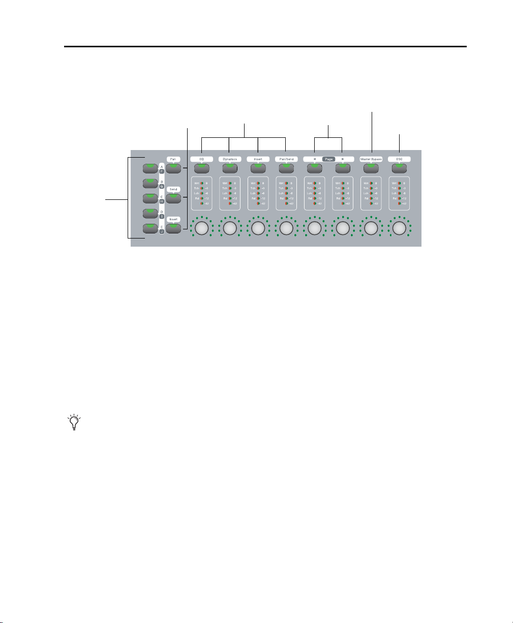
Console/Channel View Section
Channel View switches
Insert/Send
Position
Plug-in Page switches
Master Bypass switch
ESC (Escape/Cancel) switch
switches
switches
Console View
The Console and Channel View sections give you control over many on-screen elements in Pro Tools.
003 Console and Channel View switches
Both Console and Channel Views let you view and access pan, sends, or plug-ins for editing, and automation.
Console View Switches
Console View switches let you toggle 003 to show pan position, send assignments, or insert assignments for all channels on the control surface.
003 is in Console View when any of the Console View switches (Pan, Send, or Insert) is lit in the Console View section.
When you first open a Pro Tools session, the top row of the 003 is in Console View with the Pan
switch enabled (lit). This default view is sometimes called the Home View.
Think of Console View as a global view of a given control type across the entire mixer console (such
as send A for Channels 1–8).
Chapter 6: 003 Top Panel 45
Page 56
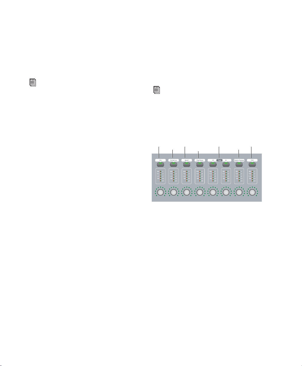
Insert/Send Position Switches
EQ
Dynamics
Insert
Pan/Send/PRE
< Page >
Master
ESC
Bypass
Channel View Section Switches
These switches determine which of the five
available insert positions (marked A–E in
Pro Tools) or ten available send positions
(marked A–J in Pro Tools) are displayed in Console View.
For information on using Console View for
specific Pro Tools workflows, see
Chapter 13, “Pro Tools Mode with 003.”
There are three Console Views, based on their
corresponding switch name:
Pan Switch When enabled (lit), 003 is in Pan
View. This is the default View when you first
open a Pro Tools session.
In this view, rotary encoders adjust channel pan
positions, and faders adjust track volume. The
bottom row of the LCD shows the track names,
and temporarily shows the channel pan positions when the encoder is moved, or volume information when the fader is moved. The top row
of the LCD shows the pan mode (left or right)
and Main Counter.
The first four Channel View switches determine
the type of information displayed for a selected
track. The first two switches focus on particular
types of plug-ins (EQ and Dynamics), while the
second two address all types of inserts and
sends.
For information on using Console View for
specific Pro Tools workflows, see
Chapter 13, “Pro Tools Mode with 003.”
The Channel View section also includes Page
Left, Page Right, Master Bypass, and ESC
switches.
Channel View switches
Send Switch When enabled (lit), 003 is in Send
View. In this view, rotary encoders adjust Send
level and the faders adjust track volume. The
bottom row of the LCD shows the names of currently assigned sends across all channel strips
for a given send position (Sends A–J in
Pro Tools). The top row of the LCD shows the
send position and Main Counter.
Insert Switch When enabled (lit), 003 is in Insert
View. In this view, the bottom row of the LCD
shows the names of currently assigned inserts
(hardware inserts or plug-ins) across all channel
strips for a given insert position (Inserts A–E in
Pro Tools). The top row of the LCD shows the
insert position and Main Counter.
003 Series Getting Started Guide46
003 is in Channel View when any of the first
four Channel View Select switches (EQ, Dynamics, Insert, or Pan/Send) is lit in the Channel
View section.
Page 57

Think of Channel View as a way to temporarily
focus on all the plug-ins, inserts or sends on a
single channel.
EQ Switch When enabled (flashing), 003 is in
Channel View. In this view, 003 identifies channels with equalizer plug-ins assigned to them by
illuminating their Channel View switches. The
top row of the LCD shows “Select EQ” and the
Main Counter. The bottom row shows track
names.
Dynamics Switch When enabled (flashing), 003
is in Channel View. In this view, 003 identifies
channels with dynamics plug-ins (such as compressors or limiters) assigned to them by illuminating their Channel Select switches. The top
row of the LCD shows “Select Dynamics” and
the Main Counter. The bottom row shows track
names.
Insert Switch When enabled (flashing), 003 is in
Channel View. In this view, 003 identifies channels with any kind of insert assigned to them
(including plug-ins or hardware I/O inserts) by
illuminating their Channel Select switches. The
top row of the LCD shows “Select Insert” and
the Main Counter. The bottom row shows track
names.
Pan/Send Switch When enabled (flashing), 003
is in Channel View. In this view, 003 identifies
channels with sends assigned to them by illuminating their Channel Select switches. The top
row of the LCD shows “Select Pan Send A–E”
and the Main Counter. The bottom row shows
track names.
Page Switches These switches provide access to
additional pages of sends, plug-in parameters or
Memory Locations. The Page switches flash to
indicate a next or previous page is available.
Plug-in Master Bypass Switch This switch lets
you bypass either a single plug-in or all plug-ins
on a channel, depending on the current view.
ESC (Escape/Cancel) Switch When flashing,
this switch acts as a cancel button for certain operations on 003 (such as Channel View selections) and many on-screen dialogs in Pro Tools.
Chapter 6: 003 Top Panel 47
Page 58

Transport and Navigation Controls
Transport controls
Jog/Shuttle wheel
Windows Show/Hide switches
Arrow keys
Fader Display switches
Transport mode switches
Mem Loc (Memory Location) switch
MIDI Map switches
Miscellaneous switches
The 003 provides a standard set of Transport controls that mirror Pro Tools on-screen controls (when
in Pro Tools mode) and conform to standard MMC commands for controlling other devices (in MIDI
mode). Navigation keys and shortcut switches support Pro Tools zooming, banking, and navigation
features.
003 transport and navigation controls
Transport Controls
These controls correspond to transport functions in Pro Tools.
RTZ (Return to Zero) Sets the playback cursor to
the beginning of the session.
REW (Rewind) Rewinds through the session
from the current cursor position.
003 Series Getting Started Guide48
FFW (Fast Forward) Fast-forwards through the
session from the current cursor position.
STOP Stops playback or recording.
Play Begins playback from the current cursor po-
sition.
Record Arms Pro Tools for recording. Clicking
Play then initiates recording on record-enabled
tracks only.
Page 59
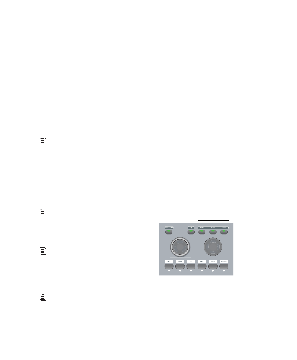
Jog/Shuttle Wheel
Arrow keys (Left, Right, Up, and Down)
Bank, Nudge, and Zoom switches
Jog/Shuttle Wheel Takeover
The dual-concentric Jog/Shuttle wheel provides
additional navigation controls.
Shuttle Mode
The outer ring of the Jog/Shuttle wheel is a Shuttle control. When you move the Shuttle ring,
003 enters Shuttle mode. In this mode, you can
play forwards or backwards at a variable rate, depending on the Shuttle position. Full clockwise
and counter-clockwise positions provide the
fastest shuttle rates. The Shuttle ring returns to
the center position (no shuttling) when you release the wheel.
For more information, see “Navigating with
the Shuttle/Jog Wheel” on page 113.
Jog Mode
The inner part of the Jog/Shuttle wheel is a Jog
control. When you move the Jog wheel, 003 enters Jog mode. In this mode, you can move the
session transport (and cursor) forwards or backwards.
When using the Jog/Shuttle wheel, keyboard
and mouse commands are not supported, and
most 003 controls are unavailable. 003 faders
can be used at the same time as the Jog/Shuttle
wheel. However, 003 transport controls disable
the Jog/Shuttle wheel.
Normal operating mode is returned a few seconds after last touching the Jog/Shuttle wheel.
Navigation and Display Keys and Switches
These multi-purpose keys and switches control
the display of Pro Tools tracks on the 003 control surface, on-screen zoom functions, and
other Pro Tools navigation functions.
Arrow Keys
The Arrow keys are used to navigate tracks,
zoom in and out, navigate in text entry fields,
and drop Selection In and Out markers
on-the-fly.
For more information, see “Navigating with
the Shuttle/Jog Wheel” on page 113.
The Jog control can be used to bank tracks to different faders.
For more information, see “Banking Channels on 003” on page 115.
The Jog control can also be used to continuously
zoom in or out horizontally or vertically on all
tracks.
For more information, see “Working With
Memory Locations” on page 114.
Navigation and Display keys and switches
Basic Arrow key functionality is defined by the
Display switches.
Chapter 6: 003 Top Panel 49
Page 60

Fader Bank, Nudge, and Zoom Display
Mem Loc (Memory Location) switch
Switches
Record/Playback Transport Mode Switches
The Display switches define basic Arrow key
functionality, as follows:
Bank Switch When enabled (lit), the Arrow keys
let you bank 003 fader strips to the previous or
next eight tracks. You can also control and adjust selections and scroll in the Pro Tools Edit
window.
Nudge Switch When enabled (lit), the Arrow
keys let you nudge the display of tracks on 003
one track at a time. You can also control and adjust selections and scroll in the Pro Tools Edit
window.
Zoom Switch When enabled (lit), the Arrow keys
zoom the Pro Tools Edit window display.
Additional Arrow Key Functionality
You can use the Arrow keys to perform additional functions in Pro Tools, regardless of the
active Display switch.
For more information, see “Navigating in
the Edit Window” on page 112.
Loop Play Switch Toggles Loop Playback on and
off
Loop Rec Switch Toggles Loop Record mode on
and off
QuickPunch Switch Toggles QuickPunch Record
mode on and off
Mem Loc (Memory Location)
Switch
The Mem Loc (Memory Location) switch provides access to all Memory Locations in a
Pro Tools session and can be used to set Memory
Locations.
For more information, see “Working With
Memory Locations” on page 114.
Windows Show/Hide Switches
Plug-in Switch Opens or closes the window for
the currently selected plug-in
Mix Switch Opens, brings forward, or closes the
Pro Tools Mix window
Edit Switch Opens, brings forward, or closes the
Pro Tools Edit window
003 Series Getting Started Guide50
Memory Location switch
Page 61

Miscellaneous Switches
Save Switch Pressing the Save switch twice is
equivalent to choosing File > Save in Pro Tools.
Undo Switch Pressing the Undo switch is equivalent to choosing Edit > Undo in Pro Tools. (See
the Pro Tools Reference Guide for details on multiple undo capabilities.)
Focus In Pro Tools mode, this switch toggles the
LCD display between the current plug-in view
and the previous 003 view (such as Console or
Channel View).
To toggle between a plug-in view and the original
view:
Press the Focus switch.
Enter (OK) Switch Pressing the Enter switch is
equivalent to pressing Return or Enter on the
computer keyboard. This lets you OK on-screen
dialogs or create new Memory Locations in
Pro Tools directly from the control surface.
Utility Switch When enabled (lit), 003 enters
Utility mode. In this mode, you can run pre-programmed diagnostic tests of the 003 unit (such
as fader movement and LEDs) and reset MIDI
mappings to their factory presets. The Utility
switch is unavailable in Pro Tools mode.
See Appendix C, “Utility Mode (003 Only)”
for more information.
Fader Mute In Pro Tools mode, this switch temporarily suspends 003 fader movement. When
enabled (flashing), this lets you work with
Pro Tools and monitor audio playback without
fader noise.
The Fader Mute feature has no effect on fader
automation or audio levels during playback.
To toggle fader movement on and off:
While in Pro Tools mode, press the Fader
Mute switch
MIDI Map Switches
003 provides switches for using the control surface as a MIDI controller.
For more information, see Chapter 14, “Using MIDI Mode with 003.”
MIDI Map A and B Switches When one of these
switches is enabled (lit), 003 is in MIDI mode. In
this mode, 003 functions as a MIDI control surface for external devices and applications other
than Pro Tools. 003 supports two different
banks of MIDI Map presets, corresponding to
MIDI Map switch A and B.
MIDI Edit In MIDI mode, this switch lets you
edit and name custom MIDI maps.
MIDI Recall In MIDI mode, this switch lets you
recall and select MIDI map presets.
Chapter 6: 003 Top Panel 51
Page 62

Automation Section
Write switch
Touch switch
Latch switch
Read switch
Off switch
Suspend switch
Option/Alt (All) switch
Shift (Add) switch
Command/Ctrl switch
Ctrl/Win switch
This section provides switches for controlling
how automation data is written and played
back.
Automation section
Automation Mode Switches
The Write, Touch, Latch, Read, and Off switches
are used to set the Pro Tools Automation mode
for any track.
When the Meter switch is set to Auto, the Meter
LEDs for each channel display its Automation
status.
For more information, see “Working with
Automation” on page 116.
Automation Switch LEDs
The Write, Touch, Latch, and Read switch LEDs
individually light when at least one channel has
the corresponding Automation mode. The Off
switch LED flashes when no channels are set to
Write, Touch, or Latch, and at least one channel’s Automation mode is set to Off.
Suspend Switch
When enabled (flashing), automation is suspended for all channels.
For more information, see “Working with
Automation” on page 116.
Modifiers Section
The Modifiers section includes four switches for
modifying commands in combination with 003
switches, keyboard shortcuts, and Right-click
commands in Pro Tools:
Shift (Add) Switch This switch lets you extend a
track selection or add to a group of selected
items.
Option/Alt (All) Switch This switch lets you apply an action or command to all tracks in a
Pro Tools session.
Ctrl/Win Switch This switch lets you temporarily disengage a control from grouped behavior.
Command/Ctrl Switch This switch lets you
fine-adjust controls and automation breakpoints.
Multiple LEDs light when there are channels
with different Automation modes.
003 Series Getting Started Guide52
003 keyboard modifier keys
Page 63

003 Shortcuts
Input 1-4 Gain control
Mic/DI and HPF switches for Inputs 1–4
Modifier switches provide shortcuts for 003
functions that can be accomplished without using your computer’s keyboard or mouse.
For a list of 003 shortcuts, see “003 Top
Panel Shortcuts” on page 117.
Pro Tools Shortcuts
For increased operational speed, there are many
Pro Tools keyboard and Right-click shortcuts to
give you fast access to a wide variety of tasks.
These shortcuts in Pro Tools use modifier keys,
(such as the Shift key) which are pressed in combination with other keys or with a mouse action.
003 Modifier switches mirror the functions of
modifier keys on the computer keyboard. For example, 003’s Shift (Add) switch is equivalent to
your keyboard’s Shift key.
:
003 Switch
Shift (Add) Shift Shift
Option/Alt
(All)
Ctrl/Win Control Win
Command/
Ctrl
003-to-QWERTY
(Mac)
Option Alt
Command Control
003-to-QWERTY
(Windows)
You can use the Modifier switches in any combination with keys on your computer or a
mouse action while working with Pro Tools.
For a complete list of Pro Tools keyboard
and Right-click shortcuts, refer to the Shortcuts Guide for your computer platform.
Mic/DI Input Controls
There are four high-quality preamplifiers with
adjustable gain and phantom power (switchable
in pairs, for Inputs 1–2 and Inputs 3–4). The
phantom power switches are on the back panel.
Inputs 1–4 show up as “Analog 1–4” in the default Pro Tools I/O Setup.
Mic/DI Input controls for Inputs 1–4
Inputs 1–4 have the following controls:
Input 1–4 Gain Controls Each knob adjusts gain
for the input, with a range of +15 dB to +60 dB
of gain.
Mic/DI Switches (Inputs 1–4) Each switch toggles the corresponding input between microphone (unlit) or DI input (lit).
The DI and Mic switch LEDs indicate the current
source input. The LEDs blink rapidly when the
input is clipping.
Engage the Mic switch only if you have an
XLR cable plugged into the mic connector.
Leaving the switch engaged with nothing
connected may introduce low-level noise.
HPF (High Pass Filter) Switches (Input
1–4) These switches enable a high pass filter
(75 Hz, 12 dB/octave rolloff) on the corresponding input, for filtering out rumble or AC hum.
The HPF LEDs are lit when the switch is enabled.
Chapter 6: 003 Top Panel 53
Page 64
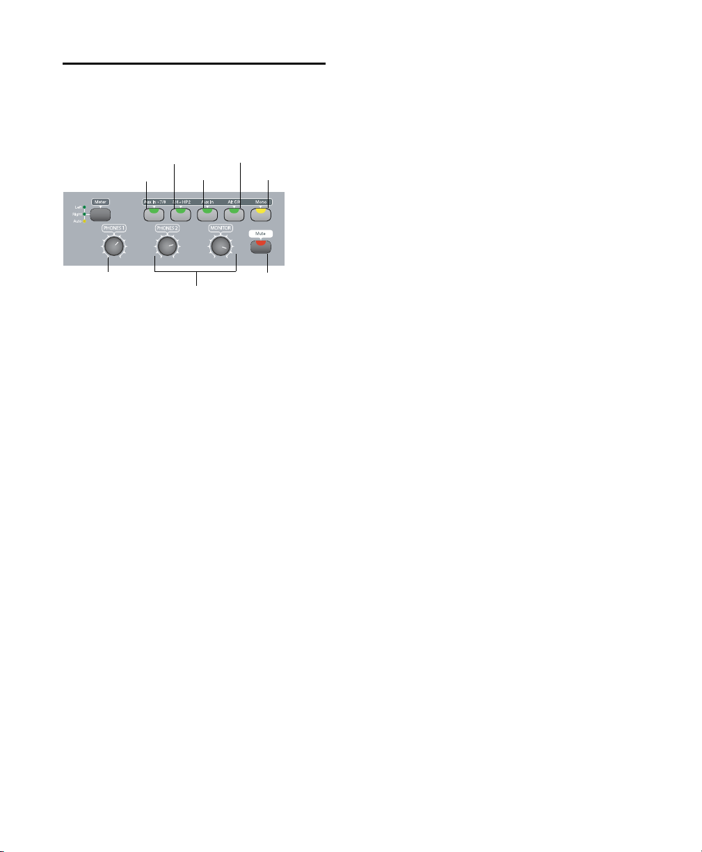
Monitor Section
3/4-HP2 switch
Aux In 7/8 switch
Input Level control
Headphone 1 and 2 Level control
Aux In switch
Mono switch
Alt CR switch
Monitor Mute switch
The Monitor section provides the following
control room monitoring features:
Monitor and headphone controls
Alt CR (Control Room) Switch This switch mutes
the Main Monitor output and routes the signal
to the Alt Monitor output.
Mono Switch This switch temporarily combines
Output 1–2 in the Main and Alt Monitor Outputs and the Headphone Outputs. This is helpful for checking the phase relationships of stereo
material.
Monitor and Headphone Level Controls
Monitor Level Control These knobs control the
volume of the Main and Alt Monitor Outputs.
These outputs mirror Analog Outputs1–2, which
correspond to outputs 1–2 in Pro Tools.
Alternate Input Routing Controls
Aux In to 7/8 Switch This switch routes the Aux
In input pair to Inputs 7 and 8 of Pro Tools, and
does not send it to the Main Monitor Outputs
unless this routing is set up in Pro Tools, or the
Aux In (to Monitor) switch is engaged. This lets
you route an alternate input signal (such as a CD
player) directly into Pro Tools without the need
to repatch any cables.
When Aux In to 7/8 is enabled (lit), Analog Inputs 7–8 are disabled.
3/4-HP2 Switch This switch sets the Headphone
2 Output to mirror Output pair 3–4.
Aux In (to Monitor) Switch This switch routes
the Aux In input pair directly to the Main Monitor and Headphone Outputs.
If you press the Aux In (to Monitor) switch in
conjunction with the Aux In to 7/8 switch, you
will hear the pre-fader input of the Aux In in the
Main Monitor outputs, and can record that input into Pro Tools from Inputs 7/8. Additionally, if you send the output of any track with inputs 7/8 back to the Main Monitor outputs, this
can result in a doubled signal.
Headphone 1 and 2 Level Controls These knobs
control the volume of the independent Headphone Outputs. The Headphone Outputs normally mirror outputs 1–2 in Pro Tools, and are
independent of the Monitor Outputs.
Headphone 2 mirrors output pair 3–4 when the
3/4-HP2 switch is enabled (lit). Both headphones include Aux In signal when Aux In (to
monitor) is enabled.
Headphone output is not affected by the status
of the Monitor Mute switch, but does follow status of the Mono switch.
Monitor Mute Switch This switch mutes the
Main and Alt Monitor Outputs only, and has no
effect on the Headphone Outputs. Monitor
Mute is automatically engaged when you power
up the unit.
Headphone Jacks
Headphone Output 1 and 2 jacks accept standard 1/4-inch stereo headphone connectors.
The jacks are located on the front of the 003.
003 Series Getting Started Guide54
Page 65

chapter 7
Mic/DI and HPF switches for Inputs 1–4
Power switch
Input 1-4 Gain control
Headphone jacks
Monitor section
Status indicators
003 Rack Front Panel
The 003 Rack front panel includes controls for
Inputs 1–4, options for routing outputs and
monitoring alternate input sources, and indicators for connections status, sync source, and
MIDI data.
Figure 2. 003 Rack front panel
Power Switch
The Power switch is located on the front panel.
Headphone Jacks
Headphone Output 1 and 2 jacks accept standard 1/4-inch stereo headphone connectors.
Chapter 7: 003 Rack Front Panel 55
Page 66

Mic/DI Input Controls
Monitor Section
There are four high-quality preamplifiers with
adjustable gain and phantom power (switchable
in pairs, for Inputs 1–2 and Inputs 3–4). The
phantom power switches are on the back panel.
Inputs 1–4 show up as “Analog 1–4” in the default Pro Tools I/O Setup.
Inputs 1–4 have the following controls:
Input 1–4 Gain Controls Each knob adjusts gain
for the input, with a range of +15 dB to +60 dB
of gain.
Mic/DI Switches (Inputs 1–4) Each switch toggles the corresponding input between microphone (unlit) or DI input (lit).
The DI/Mic switch LEDs indicate the current
source input. The LEDs blink rapidly when the
input is clipping.
Engage the Mic switch only if you have an
XLR cable plugged into the mic connector.
Leaving the switch engaged with nothing
connected may introduce low-level noise.
The Monitor section provides the following
control room monitoring features:
Monitor and Headphone Level Controls
Headphone 1 and 2 Level Controls These knobs
control the volume of the independent Headphone Outputs. The Headphone Outputs normally mirror outputs 1–2 in Pro Tools, and are
independent of the Monitor Outputs.
Headphone 2 mirrors output pair 3–4 when the
3/4-HP2 switch is enabled (lit). Both headphones include Aux In signal when Aux In (to
monitor) is enabled.
Headphone output is not affected by the status
of the Monitor Mute switch, but does follow status of the Mono switch.
Monitor Level Control These knobs control the
volume of the Main and Alt Monitor Outputs.
These outputs mirror Analog Outputs 1–2,
which correspond to outputs 1–2 in Pro Tools.
HPF (High Pass Filter) Switches (Input 1–4)
These switches enable a high pass filter (75 Hz,
12 dB/octave rolloff) on the corresponding input, for filtering out rumble or AC hum. The
HPF LEDs are lit when the HPF switch is enabled
(lit).
003 Series Getting Started Guide56
Page 67

Alternate Input Routing Controls
Aux In to 7/8 Switch This switch routes the Aux
In input pair directly to Inputs 7–8 of Pro Tools,
and does not send it to the Main and Alt Monitor Outputs. This lets you route an alternate input signal (such as a CD player) directly into
Pro Tools without the need to repatch any cables.
When Aux In to 7/8 is enabled (lit), Analog Inputs 7–8 are disabled.
3/4-HP2 Switch This switch sets Headphone 2
Output to mirror Output pair 3–4.
Aux In (to Monitor) Switch This switch routes
the Aux In input pair directly to the Main Monitor and Headphone Outputs.
Alt CR (Control Room) Switch This switch mutes
the Main Monitor output and routes the signal
to the Alt CR output.
Mono Switch This switch temporarily combines
Output 1–2 in the Main and Alt Monitor Outputs and the Headphone Outputs. This is helpful for checking the phase relationships of stereo
material.
Monitor Mute Switch This switch mutes the
Main and Alt Monitor Outputs only, and has no
effect on the Headphone Outputs. Monitor
Mute is automatically engaged when you power
up the unit.
Status Indicators
Host (“1394”) Status Indicator
The Host status LED, marked “1394” below its
LED, indicates that communication has been established between the unit and Pro Tools LE
software (or another software application)
through FireWire.
Sync Indicators
The Sync LEDs indicate the current clock source.
When the current clock source is not established, the respective LED flashes.
If none of the Sync LEDs are lit, 003 Rack’s clock
source is set to Internal.
There are three Sync LEDs:
W Clk (Word Clock) LED L i gh t s w he n c lo c k i ng t o
Word Clock.
S/PDIF LED Lights when clocking to the S/PDIF
on the RCA or Optical port.
ADAT LED Lights when clo cking to ADA T on the
Optical port.
MIDI Data Indicators
The MIDI Data LEDs indicate the presence of
MIDI data on the MIDI In, MIDI Out 1, or MIDI
Out 2 ports. Individual LEDs are provided for
each port. Active sensing is not indicated.
Chapter 7: 003 Rack Front Panel 57
Page 68

003 Series Getting Started Guide58
Page 69

chapter 8
12345678
HPF
Pad
48V
Line
DI
1 3 5 7
2 4 6 8
Input Channel Gain Controls
Headphone jacks
Monitor section
Status indicators
Power switch
Input Channel Select switches
Line-DI, 48V, HPF, and Pad switches
Front Panel DI 1 input
003 Rack+ Front Panel
The 003 Rack+ front panel includes controls for
Inputs 1–8, options for routing outputs and
monitoring alternate input sources, and indicators for connections status, sync source, and
MIDI data. It also includes a 1/4” DI input
linked to channel 1.
Power Switch
The Power switch is located on the front panel.
Headphone Jacks
Headphone output jacks 1 and 2 accept standard 1/4-inch stereo headphone connectors.
Front Panel DI 1 Input
The front panel DI 1 input routes to Input Channel 1 and accepts 1/4-inch balanced (TRS) and
unbalanced (TS) cables. This input supersedes
the rear panel channel 1 Line/DI input. The
Line-DI switch for Channel 1 must be engaged
(see “Line-DI” on page 60).
Figure 3. 003 Rack+ front panel
Chapter 8: 003 Rack+ Front Panel 59
Page 70

Mic and Line/DI Input Controls
The 003 Rack+ has eight input channels, each
featuring a high-quality preamplifier with adjustable gain, phantom power, a high-pass filter,
and a pad. These inputs show up as “Analog
1–8” in the default Pro Tools I/O Setup.
Inputs 1–8 have the following controls:
Input Channel Gain Controls
Each knob adjusts gain for the input, with a
range of +15 dB to +60 dB of gain. Gain control
applies to mic, line, or DI input signals, as well
as the front panel DI input.
Input Channel Select Switches
48V When enabled (lit red), 48 volts is applied
to the mic (XLR) input of the selected channel
for mics requiring phantom power (such as condenser mics).
If the Line-DI switch is enabled, 48V phantom power will not be applied to the
1/4-inch input.
HPF (High-Pass Filter) When enabled (lit
green), an analog 75 Hz, 12 dB/octave rolloff
high-pass filter is applied to the selected channel’s mic or Line/DI input for filtering out rumble or AC hum.
Pad When enabled (lit green), a –20 dB pad is
applied to the selected channel’s mic or Line/DI
input.
Pressing an Input Channel Select switch gives
you access to that channel’s Control switches.
Only one channel can be selected at a time, and
the following switches will be lit or unlit depending on the status of the selected channel:
Line-DI When enabled (lit orange), the selected
channel receives input from the corresponding
Line/DI (1/4” TRS) input (or the front panel DI if
channel 1 is selected). These combination inputs accept both balanced or unbalanced
line-level signals (from sources like outboard effect units), and low-level instrument signals
(from sources like guitars and basses).
When unlit, the selected channel receives input
from the mic (XLR) input.
Monitor Section
The Monitor section provides the following
control room monitoring features:
Monitor and Headphone Level Controls
Headphone 1 and 2 Level Controls These knobs
control the volume of the independent Headphone Outputs. The Headphone Outputs normally mirror outputs 1–2 in Pro Tools, and are
independent of the Monitor Outputs.
Headphone 2 mirrors output pair 3–4 when the
3/4-HP2 switch is enabled (lit). Both headphones include Aux In signal when Aux In (to
monitor) is enabled.
Headphone output is not affected by the status
of the Monitor Mute switch, but does follow the
status of the Mono switch.
003 Series Getting Started Guide60
Page 71

Monitor Level Control These knobs control the
volume of the Main and Alt Monitor Outputs.
These outputs mirror Analog Outputs 1–2,
which correspond to outputs 1–2 in Pro Tools.
Status Indicators
Host (“1394”) Status Indicator
Alternate Input Routing Controls
Aux In to 7/8 Switch This switch routes the Aux
In input pair directly to Inputs 7–8 of Pro Tools,
and does not send it to the Main and Alt Monitor Outputs. This lets you route an alternate input signal (such as a CD player) directly into
Pro Tools without the need to repatch any cables.
When Aux In to 7/8 is enabled (lit), Analog Inputs 7–8 are disabled.
3/4-HP2 Switch This switch sets Headphone 2
Output to mirror Output pair 3–4.
Aux In (to Monitor) Switch This switch routes
the Aux In input pair directly to the Main Monitor and Headphone Outputs.
Alt CR (Control Room) Switch This switch mutes
the Main Monitor output and routes the signal
to the Alt CR output.
Mono Switch This switch temporarily combines
Output 1–2 in the Main and Alt Monitor Outputs and the Headphone Outputs. This is helpful for checking the phase relationships of stereo
material.
Monitor Mute Switch This switch mutes the
Main and Alt Monitor Outputs only, and has no
effect on the Headphone Outputs. Monitor
Mute is automatically engaged when you power
up the unit.
The Host status LED, marked “1394” below its
LED, indicates that communication has been established between the unit and Pro Tools LE
software (or another software application)
through FireWire.
Sync Indicators
The Sync LEDs indicate the current clock source.
When the current clock source is not established, the respective LED flashes.
If none of the Sync LEDs are lit, 003 Rack’s clock
source is set to Internal.
There are three Sync LEDs:
W Clk (Word Clock) LED L i gh t s w he n c lo c k i ng t o
Word Clock.
S/PDIF LED Lights when clocking to the S/PDIF
on the RCA or Optical port.
ADAT LED Lights when clo cking to ADA T on the
Optical port.
MIDI Data Indicators
The MIDI Data LEDs indicate the presence of
MIDI data on the MIDI In and MIDI Out ports.
Individual LEDs are provided for each port. Active sensing is not indicated.
Chapter 8: 003 Rack+ Front Panel 61
Page 72

003 Series Getting Started Guide62
Page 73

chapter 9
003 and 003 Rack Back Panels
The 003 and 003 Rack back panels include audio, MIDI and computer connectors for the unit
(see See Figure 4 on page 64). The functions of
each connector and their associated switches are
explained in this section.
The 003 and 003 Rack have identical connectors. The 003’s Power switch is on its back panel,
whereas the 003 Rack’s Power switch is on its
front panel.
Digidesign does not recommend the use of
unbalanced cables. Unbalanced connections may introduce noise into your audio
system. Whenever possible, use balanced
cables to make connections to 003 and
003 Rack.
Operating Levels and Headroom
All 003 and 003 Rack audio inputs and outputs
are set for 14 dB of headroom below 0 dB, or full
code. This means at the nominal reference input
level (+4 dBu or –10 dBV) you can have up to
14 dB of headroom before input or output clipping occurs.
Sample Rate and Resolution Support
The Analog-to-Digital and Digital-to-Analog
converters on all 003 and 003 Rack analog inputs and outputs, as well as the S/PDIF Digital
I/O ports, support sample rates of 44.1, 48, 88.2,
and 96 kHz. The Optical port can be set for eight
channels of ADAT Optical I/O (supporting up to
48 kHz) or two channels of S/PDIF Optical I/O.
All the analog and digital inputs and outputs on
003 and 003 Rack support up to 24-bit resolution audio.
The maximum input and output of 003 or
003 Rack using balanced TRS cables on any of
the +4 dBu, 1/4-inch connectors is +18 dBu
(6.15 Vrms).
Chapter 9: 003 and 003 Rack Back Panels 63
Page 74

Figure 4. 003 back panel
Mic and DI Inputs 1-4
Analog Inputs 5-8 (and Level switch
Kensington Lock port
Link indicator
Analog Outputs 1-8
Main and Alt
FireWire ports
Monitor Outputs
Aux In
MIDI In
MIDI Outs
Footswitch
Optical I/O
S/PDIF I/O
Word C lock
AC power connector
Power switch
(and Phantom Power switches)
Analog Inputs
Mic Inputs 1–4
These are balanced, three-conductor XLR connectors for microphone-level analog inputs.
Gain is controlled by the corresponding Input
Gain Control knob (located on the top panel of
003, and on the front panel of 003 Rack). The
source (Mic, Line, or DI) is chosen using the
Mic/DI switch.
The XLR connectors on Inputs 1–4 are
wired specifically to match the impedance
of microphones. Do not use these XLR connectors for line inputs; use the 1/4-inch connectors instead.
003 Series Getting Started Guide64
DI Inputs 1–4
The DI (“Direct Inject” or “Direct Interface”) Inputs are balanced connectors for guitars and
other instrument level sources that support
1/4-inch TS connections. Operating levels for
these inputs are fixed at +4 dBu.
Gain is controlled by the corresponding Input
Gain knob (located on the top panel of 003, and
on the front panel of 003 Rack). The source
(Mic, Line, or DI) is chosen using the Mic/DI
switch.
Phantom Power Switches
These switches apply 48V phantom power to
Mic Inputs 1–2 and Mic Inputs 3–4 channel
pairs, respectively. Enable these switches for microphones that require phantom power to operate.
For more information, see “Phantom
Power” on page 78.
Page 75

Analog Inputs 5–8 and Operating Level
Switches
Analog Inputs 5–8 are balanced, 1/4-inch TRS
jacks for line-level analog audio input connections.
Operating levels for each of these line-level inputs is switchable between +4 dBu and –10 dBV,
using the Operating Level switches immediately
to the right of the input jacks.
While Inputs 5–8 do accept unbalanced connections, this may result in a noisier signal than a
balanced-to-balanced connection.
Analog Inputs 7–8 are disabled when the
Aux In to 7/8 switch is enabled (lit).
Analog Outputs
Main Analog Outputs 1–8
These are impedance balanced, 1/4-inch TRS
jacks for line-level analog audio output connections. Operating levels for these outputs are
fixed at +4 dBu.
While the Main Analog Outputs do accept unbalanced connections, this may result in a noisier signal than a balanced-to-balanced connection.
If you plan on connecting Analog Outputs
1–8 to –10 dBV gear, you may want to
place a transformer-based line level attenuator between the 003 or 003 Rack output
and the input of the destination device to
compensate for level differences.
Monitor Section
Main Monitor Outputs
These outputs support balanced TRS, or unbalanced TS, 1/4-inch connections. To monitor
your mix, these outputs can be connected to a
mixing board, directly to a monitoring system
(such as a stereo power amp, powered speakers,
or another stereo destination).
The Main Monitor Outputs play the audio that
is routed to analog outputs 1 and 2 from within
Pro Tools, respectively. These analog outputs
feature 24-bit digital-to-analog converters. Operating levels for these outputs are fixed at
+4 dBu.
Monitor gain level is controlled by the Monitor
Level control (located on the top panel of 003,
and on the front panel of 003 Rack).
Monitor output can be muted and the signal
routed to the Alt CR Output with the Alt CR
switch.
Alt Monitor Outputs
These outputs support balanced TRS, or unbalanced TS, 1/4-inch connections. These outputs
can be used to monitor your mix through an alternate, or secondary studio monitoring system,
instead of the system connected to the Main
Monitor Outputs.
The Alt Monitor Out Left and Right play the audio that is routed to analog outputs 1 and 2 from
within Pro Tools, respectively. These analog
outputs feature 24-bit digital-to-analog converters. Operating levels for these outputs are fixed
at +4 dBu.
Monitor gain level is controlled by the Monitor
Level control (located on the top panel of 003,
and on the front panel of 003 Rack).
Chapter 9: 003 and 003 Rack Back Panels 65
Page 76

These outputs are enabled when the Alt CR
switch is enabled (lit).
Aux In
These are balanced, 1/4-inch TRS connectors for
connecting alternate audio sources such as CD
players or tape decks. The signal from these inputs can be routed directly to the Main Monitor
Outputs (for monitoring) or to Inputs 7–8 (for
direct input into Pro Tools) from the top panel
of 003, or the front panel of 003 Rack.
Operating levels for these inputs are fixed at
+4 dBu.
When the Aux In switch is enabled (lit), Aux In
signal is routed to the Main Monitor Outputs.
Audio in Pro Tools that is routed to Analog 1–2
will not be mirrored at the Monitor Outputs.
When the Aux In to 7/8 switch is enabled (lit),
Aux In signal is routed to Inputs 7–8 and does
not pass directly to the Monitor Outputs.
When the Alt CR switch is enabled (lit), audio
routed to Aux In will pass out the Alt Monitor
Outputs.
003 and 003 Rack support consumer mode S/PDIF
output format (IEC60958-3) at sample rates of
44.1 kHz and 48 kHz, and professional mode
S/PDIF output format (IEC60958-4) at sample
rates of 88.2 kHz and 96 kHz. For information
on which S/PDIF formats are supported by your
S/PDIF-compatible gear, see the manufacturer’s
documentation.
Optical I/O
These are a pair of TOSLINK-style connectors for
ADAT Optical (8 channels of I/O) or S/PDIF Optical (2 channels of I/O) devices. You can choose
between these Optical I/O formats in the
Pro Tools Hardware Setup dialog.
The Optical port can be set for eight channels of
ADAT Optical I/O (supporting up to 48 kHz) or
two channels of S/PDIF Optical I/O.
The Optical I/O ports support 24-bit, 20-bit and
16-bit resolutions in both modes.
Only one S/PDIF input pair can be used at a
time. For example, if you use the Optical In
for S/PDIF data, you cannot use the RCA inputs.
Digital I/O
S/PDIF Digital I/O
The S/PDIF in and out ports are unbalanced
two-conductor phono (RCA) connectors that
utilize a full 24-bit, two-channel digital data
stream.
The Sony/Philips Digital Interface Format
(S/PDIF) is used in many professional and consumer CD recorders and DAT recorders. For
highest digital signal integrity, and lower jitter,
use 75 Ohm coaxial cable for S/PDIF transfers
and keep the cable length to a maximum of 10
meters.
003 Series Getting Started Guide66
At 96 kHz, it is recommended that you use
the S/PDIF (RCA) port
The Optical I/O ports use a standard optical
“lightpipe” cable.
Digidesign recommends high-quality audio
grade optical cable for all optical connections.
When the 003 or 003 Rack is on, its Optical Out
port emits a red light.
Page 77

About Lightpipe-Compatible Devices
Lightpipe is an industry standard, eight-channel
optical digital audio connection developed by
Alesis. Lightpipe is found on many devices, including ADAT decks, modular digital
multitracks (MDMs), sound cards, standalone
A/D or D/A converters, and digital consoles.
Word Clock
The Word Clock In and Out ports let you connect BNC cables to synchronize 003 and 003
Rack to incoming 1x Word clock, and synchronize other devices to Pro Tools-generated Word
clock.
MIDI Connectors
The MIDI In and MIDI Out 1 and Out 2 ports are
standard 5-pin MIDI ports. The MIDI In port
supports 16 channels of MIDI input. Each MIDI
Out port supports 16 channels of MIDI output,
for a system total of 32 channels of MIDI output.
A MIDI driver for these MIDI ports is installed
when you install Pro Tools LE, and is recognized
automatically by MIDI Studio Setup (Windows)
and Audio MIDI Setup (Mac). These connectors
accept standard 5-pin MIDI cables.
Kensington Lock Port
Use the Kensington Lock port to secure your interface with a Kensington Lock (not supplied).
For more information, visit the Kensington website (www.kensington.com).
Footswitch Jack
This connector lets you use a footswitch pedal to
control either playback start/stop or recording
punch in/out. Both QuickPunch audio
punch-in and punch-out and MIDI punch-in
and punch-out recording are supported. The
footswitch connector is designed specifically for
instantaneous (momentary) on/off pedals with
a 1/4-inch TS connector. Continuous on/continuous off pedals can also be used, but may result in unexpected behavior.
IEEE-1394 (FireWire) Ports
These ports, marked “1394” in reference to their
IEEE specification, are commonly known as
FireWire ports. These provide connections to the
computer and other FireWire devices.
FireWire offers a high rate of data transfer and
reliability that makes it ideal for audio applications (such as Pro Tools with 003 series devices).
FireWire devices can be daisy-chained together
without the need for terminators.
If you are using a Windows laptop that has
a 4-pin FireWire port (commonly labeled
“1394”), see “Additional Software on the
Pro Tools Installer Disc” on page 12 for
FireWire cable information.
Chapter 9: 003 and 003 Rack Back Panels 67
Page 78

Connecting 003 or 003 Rack and FireWire Hard
Drives
The FireWire ports on 003 and 003 Rack do not
pass data when they are powered off. If you
daisy-chain FireWire devices from your computer, it is best to connect FireWire hard drives
directly to your computer and not to the 003 series device. This will prevent hard drive errors
and data loss in case the 003 series device is powered off.
Connecting 003 to a FireWire port of an external drive that is connected to a computer
does not support maximum track count. For
information on supported PCI/PCMCIA/ExpressCard FireWire options, visit the
Digidesign website (www.digidesign.com).
Connecting Other FireWire Devices to 003 or
003 Rack
The second FireWire port on 003 or 003 Rack is
available for daisy-chaining FireWire devices
such as digital cameras or digital video recorders. Even when it is powered off, 003 and
003 Rack supply power from the computer
through their FireWire ports, letting you recharge batteries in other FireWire devices.
Link Indicator
The Link indicator lights when a valid FireWire
connection is established (between the 003 series device and a computer).
Power Switch
(003 Back Panel Only)
The Power switch for 003 is located on its back
panel.
The Power switch for the 003 Rack is located on
its front panel.
AC Power Connector
The AC power connectors on 003 and 003 Rack
accept a standard modular AC power cable.
003 and 003 Rack are auto power-selecting
(100V to 240V) and will work automatically
when plugged into an AC power receptacle in
any country.
003 and 003 Rack require AC power and
cannot be powered by the FireWire bus.
003 Series Getting Started Guide68
Page 79

chapter 10
003 Rack+ Back Panel
The 003 Rack+ back panel includes audio, MIDI
and computer connectors for the unit (see
Figure 5 on page 70) The functions of each connector and their associated switches are explained in this section.
Digidesign does not recommend the use of
unbalanced cables. Unbalanced connections may introduce noise into your audio
system. Whenever possible, use balanced
cables to make connections to the
003 Rack+.
Operating Levels and Headroom
All 003 Rack+ audio inputs and outputs are set
for 14 dB of headroom below 0 dB, or full code.
This means at the nominal reference input level
(+4dBu or –10dBV) you can have up to 14dB of
headroom before input or output clipping occurs.
The maximum input and output of the
003 Rack+ using balanced TRS cables on any of
the +4 dBu, 1/4-inch connectors is +18 dBu
(6.15 Vrms).
Sample Rate and Resolution Support
The Analog-to-Digital and Digital-to-Analog
converters on the 003 Rack+ analog inputs and
outputs, as well as the S/PDIF Digital I/O ports,
support sample rates of 44.1, 48, 88.2, and
96 kHz. The Optical port can be set for eight
channels of ADAT Optical I/O (supporting up to
48 kHz) or two channels of S/PDIF Optical I/O.
All the analog and digital inputs and outputs on
the 003 Rack+ support up to 24-bit resolution
audio.
Chapter 10: 003 Rack+ Back Panel 69
Page 80
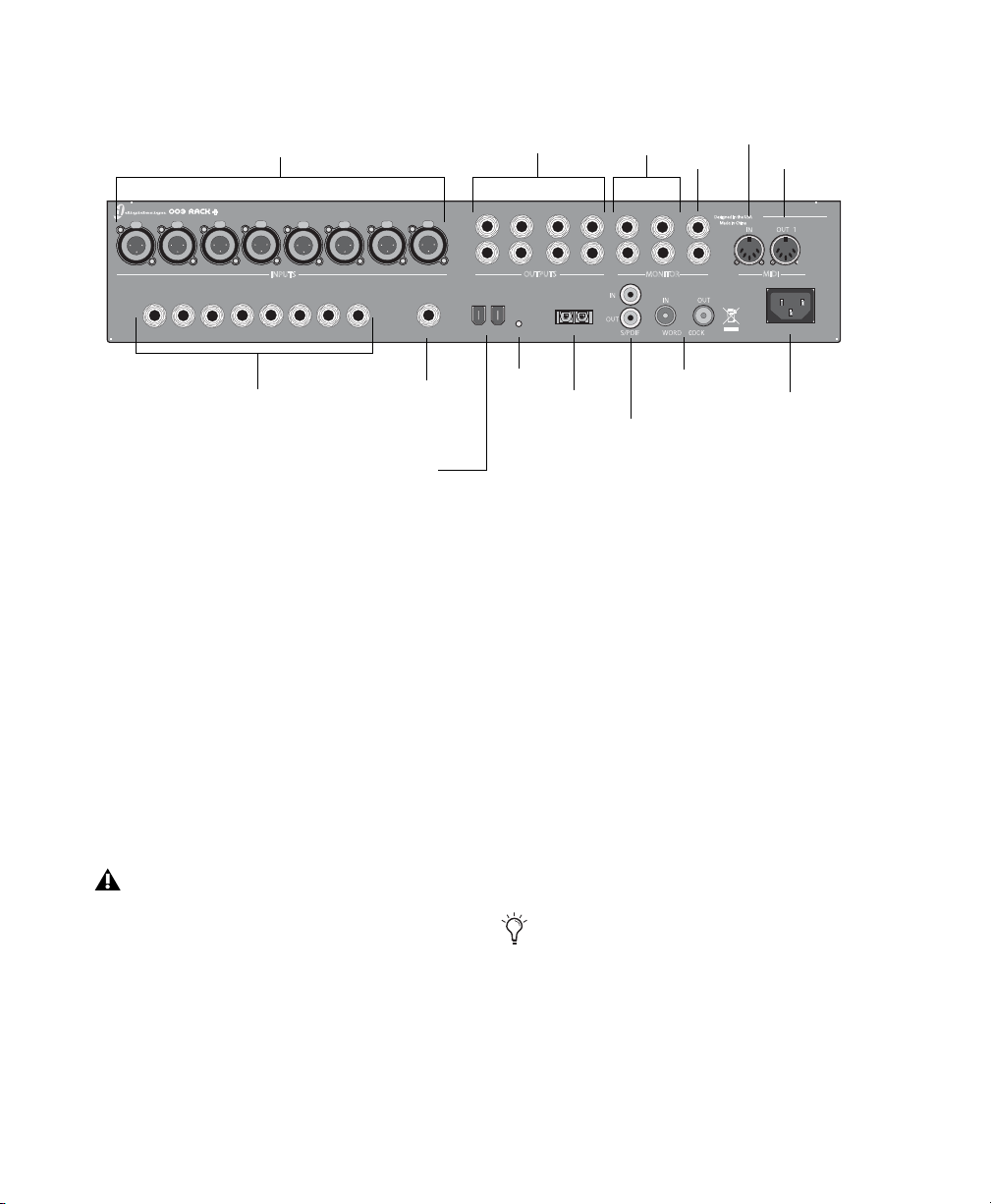
Figure 5. 003 Rack+ back panel
12 3
4 5 6
7
8
1
2
3
4
5678LRLRL
R
OUTPUTS
MAIN
MONITOR
MIDI
ALT AUX IN
FOOT SWITCH LINK1394
OUTIN
OPTICAL
AC ~ 100-240V;50-60HZ; 1A
S/N
INPUTS
Designed in the USA
Made in China
LINE / DI
1 2 3 4 5 678
Mic inputs 1-8
Line/DI inputs 1-8
Link indicator
Analog Outputs 1-8
Main and Alt
FireWire ports
Monitor Outputs
Aux In
MIDI In
MIDI Out
Footswitch
Optical I/O
S/PDIF I/O
Word C lock
AC power connector
Analog Inputs
Mic Inputs 1–8
These are balanced, three-conductor XLR connectors for microphone-level analog inputs.
Gain is controlled by the corresponding Input
Gain Control knob (located on the front panel
of 003 Rack+). The source (Mic, Line, or DI) is
chosen using the front panel Line-DI switch.
An unlit Line/DI switch means the mic (XLR) input is active.
003 Series Getting Started Guide70
The XLR connectors on Inputs 1–8 are
wired specifically to match the impedance
of microphones. Do not use these XLR connectors for line inputs; use the 1/4-inch connectors instead.
Line/DI Inputs 1–8
The combination Line/DI (“Direct Input,” “Direct Inject,” or “Direct Interface”) inputs accept
both balanced 1/4-inch balanced TRS connectors (for outboard effects and other line-level
sources) and unbalanced 1/4-inch TS connectors
(for guitars and other instrument level sources).
Gain is controlled by the corresponding Input
Gain knob (located on the front panel of
003 Rack+). The source (Mic, Line, or DI) is chosen using the Line-DI switch.
An enabled (lit) Line-DI switch means the
Line/DI (1/4-inch) input is active.
If you have an instrument connected to the
front panel DI 1 input and you have a line
or DI input connected to the rear panel
channel 1 Line/DI input, the front panel DI
1 input takes precedence over the rear panel
channel 1 Line/DI input.
Page 81

Analog Outputs
Main Analog Outputs 1–8
These are impedance balanced, 1/4-inch TRS
jacks for line-level analog audio output connections. Operating levels for these outputs are
fixed at +4 dBu.
Alt Monitor Outputs
These outputs support balanced TRS, or unbalanced TS, 1/4-inch connections. These outputs
can be used to monitor your mix through an alternate, or secondary studio monitoring system,
instead of the system connected to the Main
Monitor Outputs.
While the Main Analog Outputs do accept unbalanced connections, this may result in a noisier signal than a balanced-to-balanced connection.
If you plan on connecting Analog Outputs
1–8 to –10 dBV gear, you may want to
place a transformer-based line level attenuator between the 003 Rack+ output and the
input of the destination device to compensate for level differences.
Monitor Section
Main Monitor Outputs
These outputs support balanced TRS, or unbalanced TS, 1/4-inch connections. To monitor
your mix, these outputs can be connected to a
mixing board, directly to a monitoring system
(such as a stereo power amp, powered speakers,
or another stereo destination).
The Main Monitor Outputs play the audio that
is routed to analog outputs 1 and 2 from within
Pro Tools, respectively. These analog outputs
feature 24-bit digital-to-analog converters. Operating levels for these outputs are fixed at
+4 dBu.
Monitor gain level is controlled by the Monitor
Level control (located on the front panel of the
003 Rack+).
Monitor output can be muted and the signal
routed to the Alt CR Output with the Alt CR
switch.
The Alt Monitor Out Left and Right play the audio that is routed to analog outputs 1 and 2 from
within Pro Tools, respectively. These analog
outputs feature 24-bit digital-to-analog converters. Operating levels for these outputs are fixed
at +4 dBu.
Monitor gain level is controlled by the Monitor
Level control (located on the front panel of
003 Rack+).
These outputs are enabled when the Alt CR
switch is enabled (lit).
Aux In
These are balanced, 1/4-inch TRS connectors for
connecting alternate audio sources such as CD
players or tape decks. The signal from these inputs can be routed directly to the Main Monitor
Outputs (for monitoring) or to Inputs 7–8 (for
direct input into Pro Tools) from the front panel
of the 003 Rack+.
Operating levels for these inputs are fixed at
+4 dBu.
When the Aux In switch is enabled (lit), Aux In
signal is routed to the Main Monitor Outputs.
Audio in Pro Tools that is routed to Analog 1–2
will not be mirrored at the Monitor Outputs.
When the Aux In to 7/8 switch is enabled (lit),
Aux In signal is routed to Inputs 7–8 and does
not pass directly to the Monitor Outputs.
Chapter 10: 003 Rack+ Back Panel 71
Page 82

When the Alt CR switch is enabled (lit), audio
routed to Aux In will pass out the Alt Monitor
Outputs.
Digital I/O
S/PDIF Digital I/O
The S/PDIF in and out ports are unbalanced
two-conductor phono (RCA) connectors that
utilize a full 24-bit, two-channel digital data
stream.
The Optical I/O ports support 24-bit, 20-bit and
16-bit resolutions in both modes.
Only one S/PDIF input pair can be used at a
time. For example, if you use the Optical In
for S/PDIF data, you cannot use the RCA inputs.
At 96 kHz, it is recommended that you use
the S/PDIF (RCA) port
The Optical I/O ports use a standard optical
“lightpipe” cable.
The Sony/Philips Digital Interface Format
(S/PDIF) is used in many professional and consumer CD recorders and DAT recorders. For
highest digital signal integrity, and lower jitter,
use 75 Ohm coaxial cable for S/PDIF transfers
and keep the cable length to a maximum of 10
meters.
The 003 Rack+ supports consumer mode S/PDIF
output format (IEC60958-3) at sample rates of
44.1 kHz and 48 kHz, and professional mode
S/PDIF output format (IEC60958-4) at sample
rates of 88.2 kHz and 96 kHz. For information
on which S/PDIF formats are supported by your
S/PDIF-compatible gear, see the manufacturer’s
documentation.
Optical I/O
These are a pair of TOSLINK-style connectors for
ADAT Optical (8 channels of I/O) or S/PDIF Optical (2 channels of I/O) devices. You can choose
between these Optical I/O formats in the
Pro Tools Hardware Setup dialog.
The Optical port can be set for eight channels of
ADAT Optical I/O (supporting up to 48 kHz) or
two channels of S/PDIF Optical I/O.
Digidesign recommends high-quality audio
grade optical cable for all optical connections.
When the 003 Rack+ is on, its Optical Out port
emits a red light.
About Lightpipe-Compatible Devices
Lightpipe is an industry standard, eight-channel
optical digital audio connection developed by
Alesis. Lightpipe is found on many devices, including ADAT decks, modular digital
multitracks (MDMs), sound cards, standalone
A/D or D/A converters, and digital consoles.
Word Clock
The Word Clock In and Out ports let you connect BNC cables to synchronize your 003 Rack+
to incoming 1x Word clock, and synchronize
other devices to Pro Tools-generated Word
clock.
MIDI Connectors
The MIDI In and MIDI Out ports are standard
5-pin MIDI ports. The MIDI In port supports 16
channels of MIDI input. The MIDI Out port supports 16 channels of MIDI output.
003 Series Getting Started Guide72
Page 83

A MIDI driver for these MIDI ports is installed
when you install Pro Tools LE, and is recognized
automatically by MIDI Studio Setup (Windows)
and Audio MIDI Setup (Mac). These connectors
accept standard 5-pin MIDI cables.
FireWire offers a high rate of data transfer and
reliability that makes it ideal for audio applications (such as Pro Tools with 003 series devices).
FireWire devices can be daisy-chained together
without the need for terminators.
The 003 Rack+ only has one MIDI Out
port. However, MIDI Out 2 will still appear
in Pro Tools. When using the 003 Rack+
with Pro Tools, only use MIDI Out 1. Selecting MIDI Out 2 will produce no MIDI output information.
Kensington Lock Port
Use the Kensington Lock port, located on the
right side of the device’s chassis, to secure your
003 Rack+ with a Kensington Lock (not supplied).
For more information, visit the Kensington website (www.kensington.com).
Footswitch Jack
This connector lets you use a footswitch pedal to
control either playback start/stop or recording
punch in/out. Both QuickPunch audio
punch-in and punch-out and MIDI punch-in
and punch-out recording are supported. The
footswitch connector is designed specifically for
instantaneous (momentary) on/off pedals with
a 1/4-inch TS connector. Continuous on/continuous off pedals can also be used, but may result in unexpected behavior.
IEEE-1394 (FireWire) Ports
These ports, marked “1394” in reference to their
IEEE specification, are commonly known as
FireWire ports. These provide connections to the
computer and other FireWire devices.
If you are using a Windows laptop that has
a 4-pin FireWire port (commonly labeled
“1394”), see “Additional Software on the
Pro Tools Installer Disc” on page 12 for
FireWire cable information.
Connecting 003 Rack+ and FireWire Hard
Drives
The FireWire ports on the 003 Rack+ do not pass
data when they are powered off. If you
daisy-chain FireWire devices from your computer, it is best to connect FireWire hard drives
directly to your computer and not to the
003 Rack+. This will prevent hard drive errors
and data loss in case the 003 Rack+ is powered
off.
Connecting the 003 Rack+ to a FireWire
port of an external drive that is connected to
a computer does not support maximum
track count. For information on supported
PCI/PCMCIA/ExpressCard FireWire options, visit the Digidesign website
(www.digidesign.com).
Connecting Other FireWire Devices 003 Rack+
The second FireWire port on 003 Rack+ is available for daisy-chaining FireWire devices such as
digital cameras or digital video recorders. Even
when it is powered off, 003 Rack+ supply power
from the computer through their FireWire ports,
letting you recharge batteries in other FireWire
devices.
Chapter 10: 003 Rack+ Back Panel 73
Page 84

Link Indicator
The Link indicator lights when a valid FireWire
connection is established (between the
003 Rack+ and a computer).
AC Power Connector
The AC power connectors on 003 Rack+ accepts
a standard modular AC power cable.
003 Rack+ is auto power-selecting (100V to
240V) and will work automatically when
plugged into an AC power receptacle in any
country.
003 Rack+ requires AC power and cannot
be powered by the FireWire bus.
003 Series Getting Started Guide74
Page 85
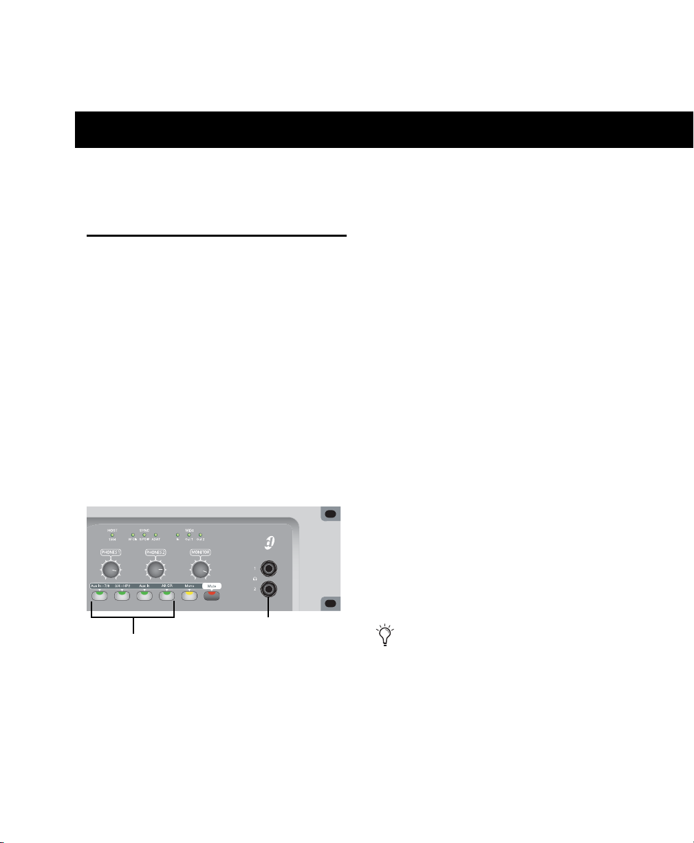
chapter 11
1/4-inch Headphone jacks
Headphone 1 and 2
Level control
Making Studio Connections
To connect headphones:
Getting Sound In and Out of Your 003 Series Device
To hear audio recorded into a Pro Tools session,
you will need to connect headphones or an external sound system (such as powered monitors
or a home stereo) to your 003 series device.
Sound from your 003 series device cannot be
played through your computer’s speakers or
your computer’s sound output.
Connecting Headphones
Connect headphones with a 1/4-inch stereo
connector (or adapter) to the Headphone 1 or 2
jack.
To adjust headphone levels:
Adjust the Headphone 1 or 2 Level knobs.
To set Headphone 2 Output to mirror Output pair
3–4:
Press the 3/4-HP2 switch.
There are two stereo 1/4-inch headphone jacks
on 003 series devices.
Headphone jacks (Front panel of 003 Rack shown)
Connecting a Sound System
The Main Monitor Outputs on the back of 003
series devices support 1/4-inch plugs. These connections can be balanced, TRS (Tip, Ring, Sleeve)
style connectors, or unbalanced connectors. To
listen to your Pro Tools session, these outputs
can be connected to any amplification system:
powered speakers, a home stereo system, or an
audio mixer.
An alternate monitoring system can be
connected to the Alt Monitor Outputs.
Chapter 11: Making Studio Connections 75
Page 86
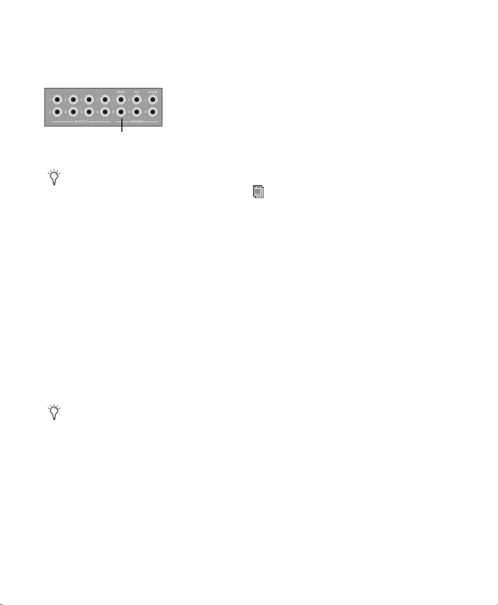
When connecting to a stereo system, connect
Main Monitor Outputs
the left channel to Main Monitor Output L, and
right channel to Main Monitor Output R.
Mirroring the Outputs on S/PDIF Out
When using your 003 series device with
Pro Tools, you can send any pair of outputs
(such as outputs 1–2) to the S/PDIF digital outputs at the same time by assigning the stereo
mix to multiple output destinations. This is
commonly known as mirroring the outputs.
Monitor Outputs (all models)
Home stereo systems often use RCA
connectors for analog audio connections. You can use an adaptor or a special cable to convert from the TRS or
TS connectors used by and 003 Rack to
the RCA connectors on your home stereo.
Main Monitor Outputs L and R play the audio
that is routed to analog outputs 1 and 2 within
Pro Tools.
The Monitor Level knob (located on the top
panel of 003, and on the front panel of 003 Rack
and 003 Rack+) adjusts the volume level of the
Monitor Outputs.
You can also connect a sound system to any of
the Analog Outputs 1–8, although you will not
have Monitor section controls available.
If you plan on connecting Analog Outputs
1–8 to –10 dBV gear, you may want to
place a transformer-based line level attenuator between your 003 series device’s output
and the input of the destination device to
compensate for level differences.
Output mirroring is useful for recording to multiple media, creating separate monitoring mixes,
or for output to digital effects processors.
For information on S/PDIF connections, see
“Connecting Equipment with Digital Ins
and Outs” on page 84
To mirror 003 series device Outputs 1–2 on the
S/PDIF outputs:
1 Open the Pro Tools session whose channel
outputs you want to mirror.
2 In the Mix window, click the Output selector
of any audio or Auxiliary Input track to select
the main output destination, for example, Analog 1–2.
3 Start-click (Windows) or Control-click (Mac)
the same Output selector and select an additional output pair from the same pop-up menu.
003 Series Getting Started Guide76
Page 87

The newly selected destination is indicated by
Mic Inputs 1-4
DI Inputs 1-4
Analog Inputs 5-8
Mic Inputs 1-8
Line/DI inputs 1-8
an additional check mark in the output pop-up
menu, and a plus sign in the Output selector.
Choosing multiple output destinations for a track
On the 003 Rack+, XLR mic inputs are labeled 18, and the combination Line/DI 1/4-inch inputs
are labeled 1-8.
Mic Inputs 1-8 (003 Rack+ shown)
Connecting Audio Inputs
003 series inputs support microphones, guitars,
keyboards, and other types of instruments.
003 series devices have eight analog inputs. On
the 003 and 003 Rack, one set of inputs is labeled Mic Inputs 1–4 and DI Inputs 1–4, and the
other four are labeled Analog 5–8.
Four Mic and DI Inputs (003 and 003 Rack shown)
Four Analog Inputs (003 and 003 Rack shown)
Line/DI Inputs 1-8 (003 Rack+ shown)
For stereo inputs, use an odd/even pair of inputs
(for example, Input 5 for the left input, and Input 6 for the right input.
You cannot use both a mic input and DI input
with the same input number at the same time.
For information about connecting specific audio sources, see “Connecting a Microphone” on
page 78, and “Connecting Instruments to 003
Series Devices” on page 81.
Chapter 11: Making Studio Connections 77
Page 88

Connecting a Microphone
XLR connector
1/4-inch connector
Mic Input 1
There are several ways to use your 003 series device with a microphone, depending on the type
of microphone and cables you use.
Mic Cables and Connectors
Some microphone cables use an XLR connector
to attach a microphone to an input (such as
those on 003 series devices). Other microphones
use a 1/4-inch connector. If you have a choice,
use an XLR connector to connect the microphone to your 003 series device to yield better
results.
XLR and 1/4-inch connectors
Most condenser microphones (such as an AKG
C3000) require phantom power to operate. Dy-
namic microphones (such as a Shure SM57) do
not require phantom power to operate, but are
not harmed by it.
Although phantom power can be used
safely with most microphones, ribbon microphones can be damaged by it. Always
turn off phantom power and wait at least
30 seconds before connecting a ribbon microphone.
003 series devices can only supply power
through a microphone cable with XLR connectors.
If you are not sure about the phantom power requirements for your microphone, see your microphone’s documentation or contact the manufacturer.
Using a Mic that Has an XLR Connector
Phantom Power
Some microphones require power to operate.
This power, called phantom power, is supplied either by a battery in the microphone, or through
an audio interface (such as your 003 series device) that can supply power through the microphone cable.
003 Series Getting Started Guide78
To use a microphone that has an XLR connector:
1 On the back of your 003 series device, plug
your microphone cable into one of the XLR mic
inputs. The inputs are numbered left to right, so
Mic Input 1 is the leftmost input.
XLR cable plugged into Mic Input 1 (003 and 003 Rack
shown)
Page 89
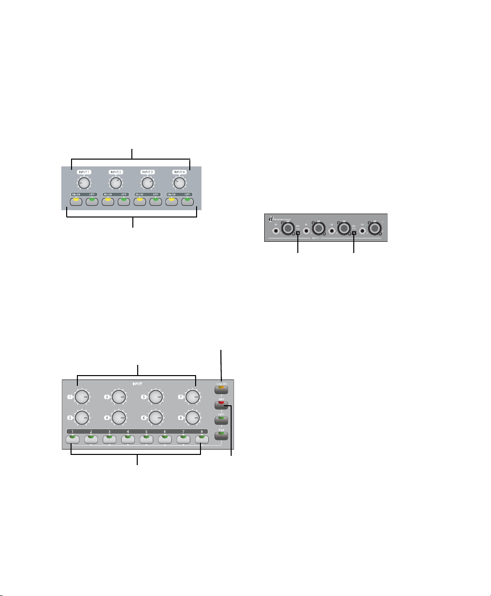
2 Depending on your device, do one of the fol-
Input 1-4 Gain control
Mic/DI and HPF switches for Inputs 1–4
Input Channel Select switches
Input Channel Control Line-DI switch
48V
Phantom
Power
switch
Input 1-8 Gain Control
Phantom Power
(Mic Inputs 1 and 2)
Phantom Power
(Mic Inputs 3 and 4)
lowing:
• If using the 003 or 003 Rack, press the
Mic/DI switch (located on the top panel of
the 003, and on the front panel of the 003
Rack) for the corresponding input so that it
is in the Mic (unlit) position.
003 and 003 Rack Mic/DI switches
– or –
• If using the 003 Rack+, press the Input
Channel Select switch (located on the front
panel) for the corresponding input and
make sure the Line-DI switch is not enabled (unlit).
3 If your microphone requires phantom power,
make sure the microphone is connected and do
one of the following depending on your device:
• If using the 003 or 003 Rack, press the
Phantom Power switch (labeled 48V) on
the back of the device for the corresponding input pair. Each Phantom Power switch
sends 48V to its corresponding input pair.
– or –
• If using the 003 Rack+, press the Input
Channel Select switch (located on the front
panel) for the corresponding input and
press the 48V switch so that it is lit (red).
Phantom Power switches (003 and 003 Rack shown)
4 When Pro Tools is launched and the input is
routed to a Pro Tools track (see “Recording a
Pro Tools Session” on page 91), you can adjust
the input level with the Input Gain Control
knobs (located on the top panel of the 003, and
the front panel of the 003 Rack and 003 Rack+).
003 Rack+ Input Channel Select switches and Input
Channel Control switches
Chapter 11: Making Studio Connections 79
Page 90

Using a Mic that Has a 1/4-Inch
Line/Inst Input 1
Input Channel Select switches
Input Channel Control Line-DI switch
Input 1-8 Gain Control
DI 1 input
Input 1-4 Gain control
Mic/DI and HPF switches for Inputs 1–4
Connector
To use a microphone that has a 1/4-inch
connector with your 003 series device:
1 Do one of the following, depending on your
device:
• If using the 003 or 003 Rack, on the back of
your device plug the 1/4-inch connector
from your microphone into one of the DI
inputs. From the back, the inputs are numbered left to right, so DI Input 1 is the leftmost input.
003 and 003 Rack with 1/4-inch cable plugged into DI
Input 1
– or –
• If using the 003 Rack+, plug your mic’s 1/4inch connector into the DI 1 1/4-inch input on the front panel (or into a rear-panel
1/4-inch Line/DI input).
2 Do one of the following, depending on your
device:
• If using the 003 or 003 Rack, press the
Mic/DI switch (located on the top panel of
the 003, and on the front panel of the 003
Rack) for the corresponding input so that it
is lit (yellow).
003 and 003 Rack+ Mic/DI switches
– or –
• If using the 003 Rack+, press the Input
Channel Select switch (located on the front
panel) for the corresponding input and
press the Line-DI switch so that it is lit (orange).
If you are using a microphone with a 1/4inch connector, do not choose the “Mic” input source because the 003 series device will
not register any signal.
003 Rack+ with 1/4-inch cable plugged into DI 1 input
003 Series Getting Started Guide80
3 When Pro Tools is launched and the input is
routed to a Pro Tools track (see “Recording a
Pro Tools Session” on page 91), you can adjust
the input level with the Input Gain Control
knob.
Page 91
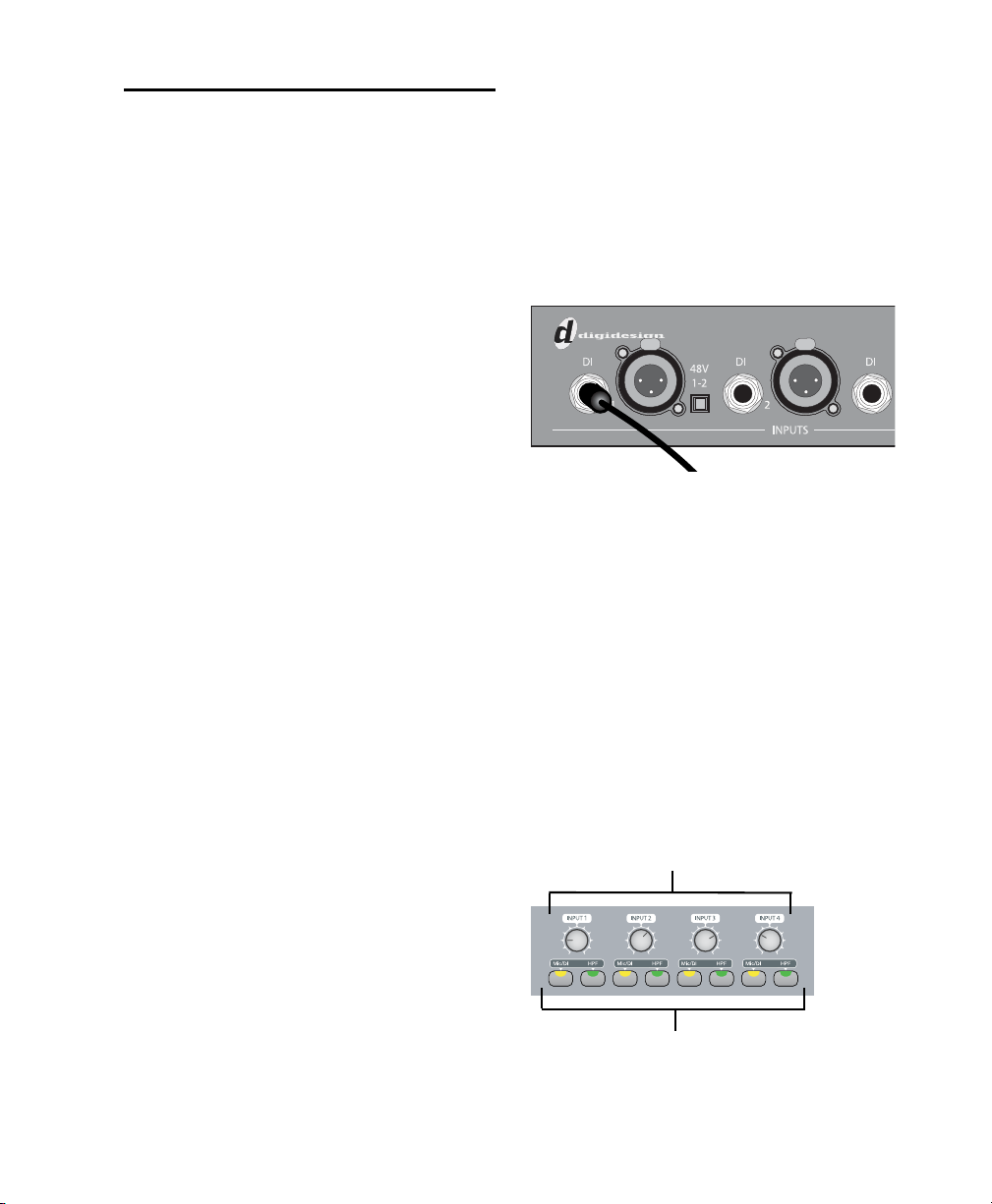
Connecting Instruments to
Line/Inst Input 1
Input 1-4 Gain control
Mic/DI and HPF switches for Inputs 1–4
003 Series Devices
The 1/4-inch inputs on 003 series devices support both higher output “line-level” devices and
low-output instruments (such as electric or
acoustic guitars). This section contains examples for connecting both types to your 003 series
device.
Instruments such as electric guitar or electric
bass usually have a lower level of output than instruments and electronic audio sources such as
mixers, samplers, keyboards, turntables, and
synthesizers.
To use a guitar with the 003 series device:
1 Do one of the following, depending on your
device:
• On the back of the 003 or 003 Rack, plug
your guitar cable into one of the DI inputs.
From the back, the inputs are numbered
left to right, so DI Input 1 is the leftmost input.
The higher level of output is commonly called
“line-level” and the instruments that produce
these higher levels are called line-level devices.
On 003 and 003 Rack, DI Inputs 1–4 support
low-level instruments and line-level instruments. Analog Inputs 5–8 support line-level instruments only.
On the 003 Rack+, Line/DI inputs 1-8 (as well as
the front panel DI 1 input) support low-level instruments and line-level instruments.
003 and 003 Rack with 1/4-inch cable plugged into DI
Input 1
– or –
• If using the 003 Rack+, plug your guitar cable into the front panel DI 1 1/4-inch input
(or into a rear-panel 1/4-inch Line/DI input).
2 Do one of the following, depending on your
device:
• If using the 003 or 003 Rack, press the
Mic/DI switch (located on the top panel of
the 003, and on the front panel of the 003
Rack) for the corresponding input so that it
is lit (yellow).
003 and 003 Rack Mic/DI switches
– or –
Chapter 11: Making Studio Connections 81
Page 92

• If using the 003 Rack+, press the Input
Input Channel Select switches
Line-DI switch
Input 1-8 Gain control
DI 1 input
Input 1-4 Gain control
Mic/DI and HPF switches for Inputs 1–4
Channel Select switch (located on the front
panel) for the corresponding input, and
press the Line-DI switch so that it is lit (orange).
003 Rack+ with 1/4-inch cable plugged into front panel
DI 1 input
For stereo inputs, (such as a stereo keyboard or
the stereo output from a mixer), use an
odd/even pair of inputs. For example, connect
the left channel to DI Input 1, and right channel
to DI Input 2.
From the back, the inputs are numbered left to
right, so DI Input 1 is the leftmost input.
Stereo keyboard plugged into Analog Inputs 5–6
3 When Pro Tools is launched and the input is
routed to a Pro Tools track (see “Recording a
Pro Tools Session” on page 91), you can adjust
the input level with the Input Gain Control
knob.
To use a keyboard or mixer with 003 or 003 Rack:
1 On the back of the 003 or 003 Rack, plug your
keyboard, mixer, or other audio source into any
of the DI inputs or Analog Inputs by doing one
of the following:
• Use Analog Inputs 5–8 if you need to select
–10 dBV or +4 dBu operating level for your
keyboard.
– or –
• Use DI Inputs 1–4 if Analog Inputs 5–8 are
unavailable, or if you do not need to set the
operating level. DI Inputs 1–4 are available
even if a mic is connected to Mic Inputs
1–4 (although both cannot be active at the
same time).
003 Series Getting Started Guide82
2 If you are using any DI inputs, press the
Mic/DI switch (located on the top panel of the
003, and on the front panel of the 003 Rack) for
the corresponding input so that it is in the DI
(lit) position.
Mic/DI switches (located on the top panel of 003, and
front panel of 003 Rack)
For line-level devices, the Input Gain Control knob should be turned down all the
way.
Page 93

3 If you are using any of the Inputs 5–8, set ei-
Operating Level switches
for Analog Inputs 5-8
Input Channel Select switches
Line-DI switch
Input 1-8 Gain control
ther a –10 dBV or +4 dBu operating level for the
corresponding input using the Operating Level
switch (located on the back panel). For information on the appropriate operating level for your
input device, see the manufacturer’s specifications.
003 and 003 Rack’s four Analog Inputs
4 Set your instrument’s volume to its optimal
level. For example, the optimal level for most
keyboards is between 80% and 100% of maximum volume.
5 When Pro Tools is launched and the input is
routed to a Pro Tools track (see “Recording a
Pro Tools Session” on page 91), if you are using
the DI Inputs you can adjust the input level with
the Input Gain Control knob.
To use a keyboard or mixer with 003 Rack+:
1 On the back of the 003 Rack+, plug your key-
board, mixer, or other audio source into any of
the Line/ DI inputs.
For stereo inputs, (such as a stereo keyboard or
the stereo output from a mixer), use an
odd/even pair of inputs. For example, connect
the left channel to Line/DI Input 1, and right
channel to Line/DI Input 2.
2 On the front panel, press the Input Channel
Select switch (located on the front panel) for
each corresponding input, making sure the
Line-DI switch is enabled (lit) for each channel.
003 Rack+ Front
3 Set your instrument’s volume to its optimal
level. For example, the optimal level for most
keyboards is between 80% and 100% of maximum volume.
4 When Pro Tools is launched and the input is
routed to a Pro Tools track (see “Recording a
Pro Tools Session” on page 91), you can adjust
the input level with the Input Gain Control
knob.
Stereo keyboard plugged into Line/DI inputs 1–2
For line-level devices, the Input Gain Control knobs should be turned down all the
way.
Chapter 11: Making Studio Connections 83
Page 94

Connecting Equipment with
RCA S/PDIF In and Out ports
Optical In and Out ports
Digital Ins and Outs
Each 003 series device provide up to ten digital
inputs and outputs, including:
• Eight channels of ADAT Optical input and
output, or two channels of Optical S/PDIF input. Digidesign recommends high-quality audio grade optical cable for all optical
connections.
• Two channels of S/PDIF digital input and output (RCA connectors)
To connect your 003 series device to a S/PDIF
digital device using RCA cables:
1 Using RCA (coaxial) cables, connect the 003
series device S/PDIF In to the S/PDIF output of
the external device.
2 Connect the 003 series device S/PDIF Out to
the S/PDIF input of the external device.
To connect your 003 series device to a S/PDIF
device using Optical (ADAT) cables:
1 Using an optical cable, connect the Optical
output on the Optical device to the Optical In
port on the 003 series device.
2 Connect the Optical input on the Optical de-
vice to the Optical Out port on the 003 series device. (When the 003 or 003 Rack is on, its
Optical Out port emits a red light.)
Digital connectors
Up to 18 channels of I/O can be achieved by using the S/PDIF RCA I/O, Optical (ADAT) I/O,
and analog I/O at the same time.
Only one S/PDIF input pair can be used at a
time. For example, if you use the optical input for S/PDIF data, you cannot use the
RCA inputs. For more information on configuring Digital I/O, see “Configuring
Pro Tools LE Software” on page 22.
For more information on each I/O type, see
“Digital I/O” on page 66
For information on connecting digital effects devices, see “Using External Effects
Devices” on page 86.
For information on recording from a Digital
I/O, see “Recording from a Digital Device”
on page 87.
To connect your 003 series device to an ADAT
device using Optical (ADAT) cables:
1 Using an optical cable, connect the Optical
output on the ADAT device to the Optical In
port on your 003 series device.
2 Connect the Optical input on the ADAT de-
vice to the Optical Out port on the 003 series device. (When your 003 series device is on, its
Optical Out port emits a red light.)
Word Clock
003 series devices provide Word Clock In and
Out connectors on the back panel that let you
synchronize, or “clock” Pro Tools LE and the
003 series device to industry standard Word
clock. Word clock is used to synchronize a wide
range of devices such as non-linear video systems and other types of equipment typically
found in professional audio facilities.
003 Series Getting Started Guide84
Page 95

With both Word clock input and output, your
Pro Tools LE system can act as Word clock
“slave” or “master.”
Do not confuse Word clock and other forms
of “clock reference” with time code and
other forms of “positional reference.” For an
overview of synchronization terminology
and concepts, see the Sync & Surround Concepts Guide.
To connect your 003 series device to Word clock:
Using high-quality, 75 Ohm BNC cables (not
included), connect the 003 series device Word
Clock In and Out connectors to the appropriate
ports on the other Word clock-capable devices
in your studio.
Using Word Clock with Pro Tools LE
Pro Tools LE with 003 series devices can act as
Word clock master, or as a slave to Word clock
supplied by an external device.
Pro Tools LE as Word Clock Master
003 series device Word clock output is always
active, letting Pro Tools supply Word clock to
any connected devices that support standard
Word clock.
To use Pro Tools LE as Word clock master:
1 Make sure all connections are correct between
the 003 series device and your external devices.
2 Configure all external devices to slave to the
Word clock coming from the 003 series device.
(Be sure to match the sample rate setting of the
Pro Tools session, and verify the termination requirements and other internal settings for the
device; see the manufacturer’s documentation if
you need more information on the particular requirements for your other equipment.)
3 Launch Pro Tools.
4 Choose Hardware > Setup.
5 Click the Clock Source pop-up menu and
choose Internal.
6 Click OK.
Pro Tools LE as Word Clock Slave
In order to slave Pro Tools to an external Word
clock source, you must configure Word clock as
the Pro Tools Clock source, as follows:
To configure Pro Tools LE with the 003 series
device as a Word clock slave:
1 Make sure all Word clock and audio connec-
tions are correct as described earlier in this section.
2 Make sure the external Word clock source is
powered on, and configured to output 1x Word
clock. (Be sure to verify any required termination; see the manufacturer’s documentation if
you need more information on the particular requirements for your device.)
3 Launch Pro Tools.
4 Choose Hardware > Setup.
5 Click the Clock Source pop-up menu and
choose Word Clock.
6 Click the Sample Rate pop-up menu and
match the sample rate of the external Word
clock source.
7 Click OK.
Chapter 11: Making Studio Connections 85
Page 96

Using External Effects Devices
003 series devices can make dedicated connections to external analog or digital devices. You
can send and return signals to analog devices using the analog inputs and outputs on 003 series
devices. You can also send and return a digital
signal to an external device that supports digital
I/O (such as a reverb unit), and monitor the return by connecting its analog outputs to available inputs on 003 series devices.
When you use the digital inputs and outputs on
your Pro Tools LE system as effects sends and returns to a digital effects device, Pro Tools LE
should be the clock master in most cases. Set
your digital effects device to accept an external
digital clock so that it synchronizes to
Pro Tools LE.
To connect an external analog device to your
system:
1 Connect each input of the external signal pro-
cessor to an available analog output on the 003
series device.
2 Connect each output of the external signal
processor to an available analog input on the
003 series device.
If you plan to use the external device as an
Insert in Pro Tools, connect it to inputs and
outputs of the same number (for example,
Input 5 and Output 5) of 003 series device.
To set up a send to an external digital effects
device (digital sends/returns only):
1 Connect the digital inputs and outputs of the
external signal processor to the appropriate digital connectors (the S/PDIF RCA connectors or
the Optical ports) on 003 series device.
2 In Pro Tools, choose Setup > Hardware.
3 Under Optical Format, do one of the follow-
ing:
• If the external effects device is a S/PDIF device and connected to the S/PDIF RCA
jacks, select ADAT (if the selected sample
rate is 44.1 or 48 kHz) or None (if the selected sample rate is 88.2 or 96 kHz). The
RCA jack is only active when Optical
S/PDIF is not enabled.
• If the external effects device is a S/PDIF device and connected to the Optical ports, select S/PDIF.
• If the external effects device is an ADAT
Optical compatible device, select ADAT.
4 Choose Internal from the Clock Source pop-
up menu.
5 Click the Sample Rate pop-up menu and select
a sample rate. The sample rate of the Pro Tools
session and external digital device must match.
If necessary, change the sample rate of the digital device.
6 Click OK.
You can use the I/O Setup dialog (Setup >
I/O) to label the inputs and outputs you are
using in Pro Tools LE and identify them as
inserts or sends when working in a session.
See the Pro Tools Reference Guide for details.
003 Series Getting Started Guide86
Page 97
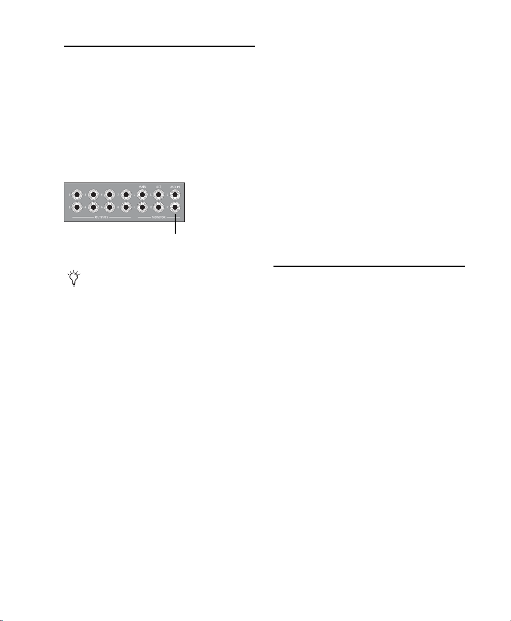
Monitoring and Recording
Aux In
from Alternate Sources
003 series devices provide a pair of additional inputs for monitoring and recording from an external sound source such as a CD player or tape
deck. This alternate input is equipped with 1/4inch TRS connectors and is designed for input
signals with a nominal operating level of
+4 dBu.
Aux In for alternate sound sources
To record an alternate sound source directly into
Pro Tools:
1 Connect the outputs of the external device to
the left and right Aux In connectors on the back
panel of the 003 series device.
2 Route the signal directly to Inputs 7–8 in
Pro Tools by pressing the Aux In to 7–8 switch
(located on the top panel of 003, and on the
front panel of 003 Rack and the 003 Rack+) so
that it is enabled (lit).
When the Aux In to 7–8 switch is enabled, Inputs 7 and 8 on the back panel are inactive. Also,
because the signal can be monitored from
Pro Tools, it no longer passes directly to the
Monitor Outputs.
To monitor an external device through the
Alternate Source Inputs, the 003 series device must be powered on.
To monitor an alternate sound source through the
Monitor Outputs of your 003 series device:
1 Connect the outputs of the external device to
the left and right Aux In connectors on the back
panel of the 003 series device.
2 Route the signal to the Monitor Output by
pressing the Aux In switch (located on the top
panel of 003, and on the front panel of 003 Rack
and the 003 Rack+) so that it is enabled (lit).
3 If you want to monitor the signal through the
Alternate Monitor Outputs, press the Alt CR
switch. Any tracks within Pro Tools that are sent
to the Monitor Outputs will not be heard.
4 Adjust Monitor Output or Headphone Output
levels to audition the input.
Recording from a Digital
Device
If you are recording from an optical or S/PDIF
device, you will need to select a Clock Source. In
most cases, you will synchronize the Pro Tools
clock to the external device.
If you are using an optical device for recording,
you also need to set the Optical Format.
To configure Pro Tools LE for a digital source:
1 Connect an ADAT or Optical S/PDIF format
device to the Optical In connector, or an RCA
S/PDIF format device to the S/PDIF In connector
on the back of the 003 series device.
2 Choose Setup > Hardware.
Chapter 11: Making Studio Connections 87
Page 98
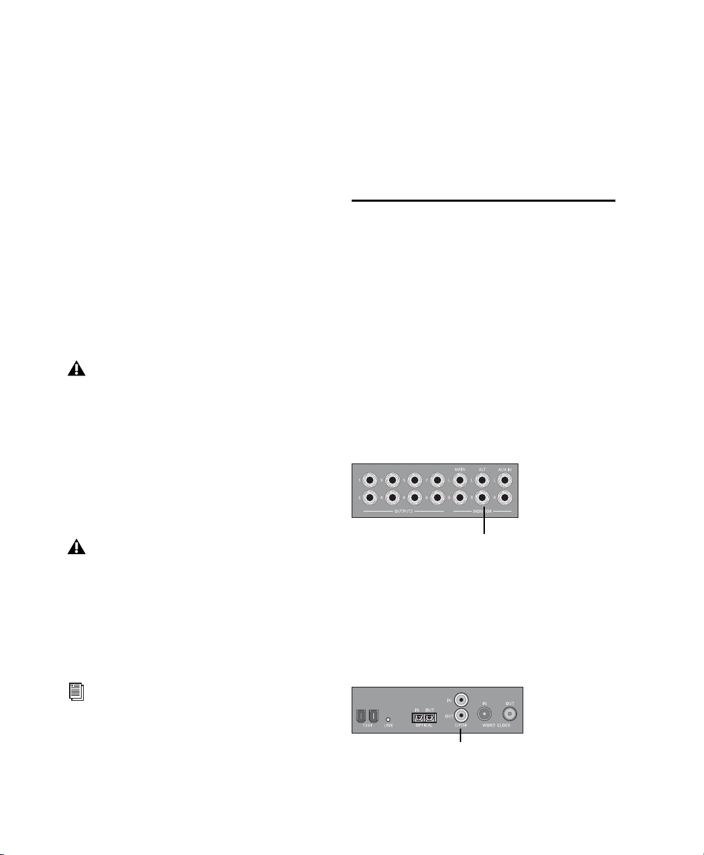
3 Under Optical Format, do one of the follow-
Alt Monitor Outputs
RCA S/PDIF In and Out ports
ing:
• If the external digital device is a S/PDIF device and connected to the S/PDIF RCA
jacks, select ADAT (if the selected sample
rate is 44.1 or 48 kHz) or None (if the selected sample rate is 88.2 or 96 kHz). The
RCA jack is only active when Optical
S/PDIF is not enabled.
– or –
• If the external digital device is a S/PDIF device and connected to the Optical ports, select S/PDIF.
– or –
• If the external digital device is an ADAT
Optical compatible device, select ADAT.
You can use only one pair of S/PDIF inputs
(either RCA or Optical) at a time.
4 From the Clock Source pop-up menu, do one
of the following:
• If you are synchronizing the Pro Tools
clock to the external device, select ADAT,
RCA (S/PDIF), or Optical (S/PDIF), depending
on where you connected your digital device.
5 Click the Sample Rate pop-up menu and select
a sample rate. The sample rate of the Pro Tools
session and external digital device must match.
If necessary, change the sample rate of the digital device.
6 Click OK.
Connecting a Recorder for Mixdowns
After you record and mix your sessions using
your 003 series device, you may want to mix
them down to a DAT, or other stereo 2-track recording device.
Connecting an Analog Deck
Connect your recorder’s inputs to the Alt
Monitor Outputs (or any other output pair) on
the back of the series device. These outputs are
1/4-inch jacks. You may need adapter cables if
your mixdown deck has RCA inputs.
Your digital input device must be connected
and powered on. If your input device is not
powered on, leave the Clock Source set to Internal.
– or –
• Select Internal if you are synchronizing the
external device to the 003 series device.
You can use the I/O Setup dialog (Setup >
I/O) to label the inputs and outputs you are
using in Pro Tools LE and identify them as
inserts or sends when working in a session.
See the Pro Tools Reference Guide for details.
003 Series Getting Started Guide88
Alt Monitor Outputs and other outputs
Connecting a Digital Deck
If you have a DAT or other digital device that
can receive S/PDIF digital audio data, connect it
to the S/PDIF In and S/PDIF Out RCA jacks on
the back of the 003 series device.
S/PDIF In and Out ports
Page 99
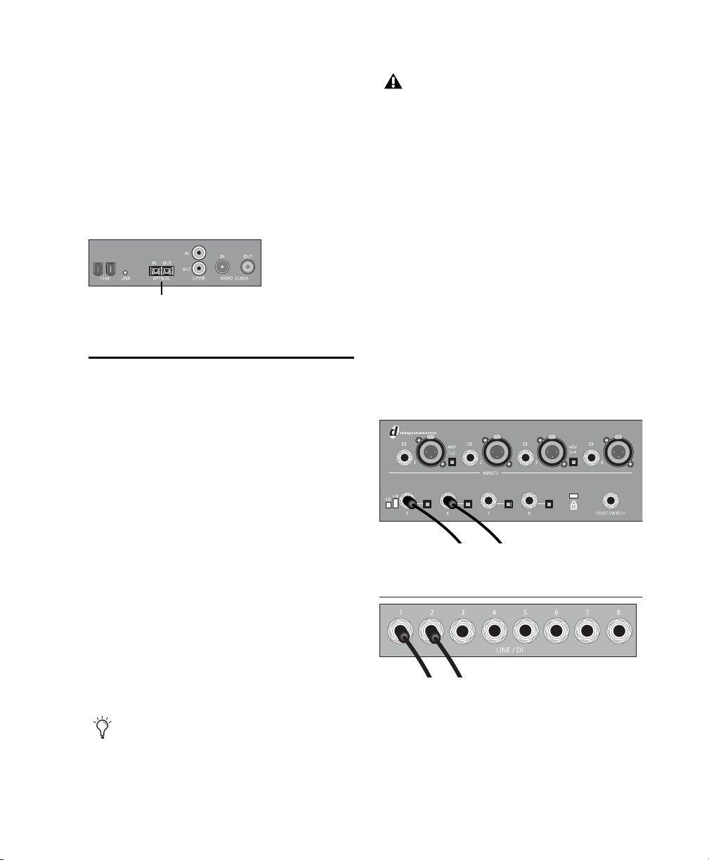
Connecting a Lightpipe-Compatible
Optical In and Out
Device (ADAT)
To connect a Lightpipe-compatible device (ADAT)
to your 003 series device:
1 Connect the Optical output on the ADAT to
the Optical In port on the 003 series device.
2 Connect the Optical input on the ADAT to the
Optical Out port on the 003 series device.
Optical In and Out ports
MIDI Connections
The MIDI ports on 003 series devices let you take
advantage of all the MIDI features of
Pro Tools LE, including recording and editing
MIDI tracks.
The 003 Rack+ only has one MIDI Out
port. However, MIDI Out 2 may still appear
in Pro Tools. When using the 003 Rack+
with Pro Tools, only use MIDI Out 1. Selecting MIDI Out 2 will produce no MIDI output information.
Monitoring MIDI Instruments with 003
Series Devices
If you have a MIDI instrument that has analog
outputs, you can connect it to your 003 series
device to monitor its output.
To connect your MIDI instrument for monitoring in
Pro Tools:
Connect the MIDI instrument’s audio output
to a Line/DI (003 Rack+) input, or to a DI or Analog Input on the back panel of the 003 or 003
Rack.
If you need additional MIDI ports you can add a
compatible MIDI interface (such as a Digidesign
MIDI I/O).
To connect your MIDI device to your 003 series
device:
1 Connect a standard 5-pin MIDI cable from the
MIDI Out port of your device to the MIDI In
port on the back panel of the 003 series device.
2 Connect another MIDI cable from the
MIDI In port of your device to one of the
MIDI Out ports on the back panel of the 003 series device.
The MIDI Out port can be selected in
Pro Tools or a supported third-party application.
MIDI instrument audio outputs plugged into 003 and
003 Rack Analog Inputs 5–6
MIDI instrument audio outputs plugged into 003 Rack+
Line/DI Inputs 1-2
Chapter 11: Making Studio Connections 89
Page 100

Using a Footswitch
The footswitch connector on your 003 series device lets you use a footswitch pedal to control either playback start/stop or recording
punch in/out. Both QuickPunch audio punchin and punch-out and MIDI punch-in and
punch-out recording are supported.
The footswitch connector is designed specifically for instantaneous (momentary) on/off
pedals with a 1/4-inch TS connector. Continuous on/continuous off pedals can also be used,
but may result in unexpected behavior.
To use a footswitch control:
1 Connect a footswitch to the footswitch con-
nector on the back panel of the 003 series device.
2 Launch Pro Tools.
3 Choose Setup > Hardware.
4 Select Record Punch In/Out or Playback
Start/Stop.
5 Click Ok.
003 Series Getting Started Guide90
 Loading...