

Page 1
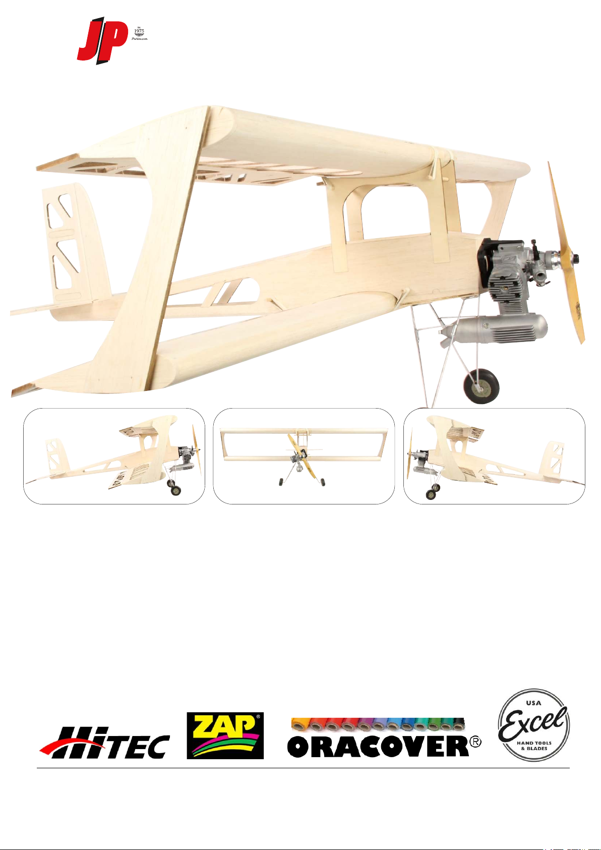
PANIC KIT
Recommended set up:-
Servo`s
Novice - Intermediate
Expert
Engine I/C
Electric
ESC
Lipo
Designed by Avicraft
- HS635HB
- HS5625MG
- SC61A-S
- SC91A-S
- EnErG C50-20 (IC 60) Brushless motor
- 90A ZTW
- Radient 4s 4000mAh 35c
Recomended build items:-
Glue - Zap
Tools - Excel
Covering - Oracover
Product specifications are subjected to change without notice. Due to ongoing development, the
actual product and recommendations may vary from what is shown.
Distributed by:-
J Perkins Distribution
Northdown Business Park, Ashford Road, Lenham, Maidstone, Kent ME17 2DL
Tel :- 01622 854 300
Page 2
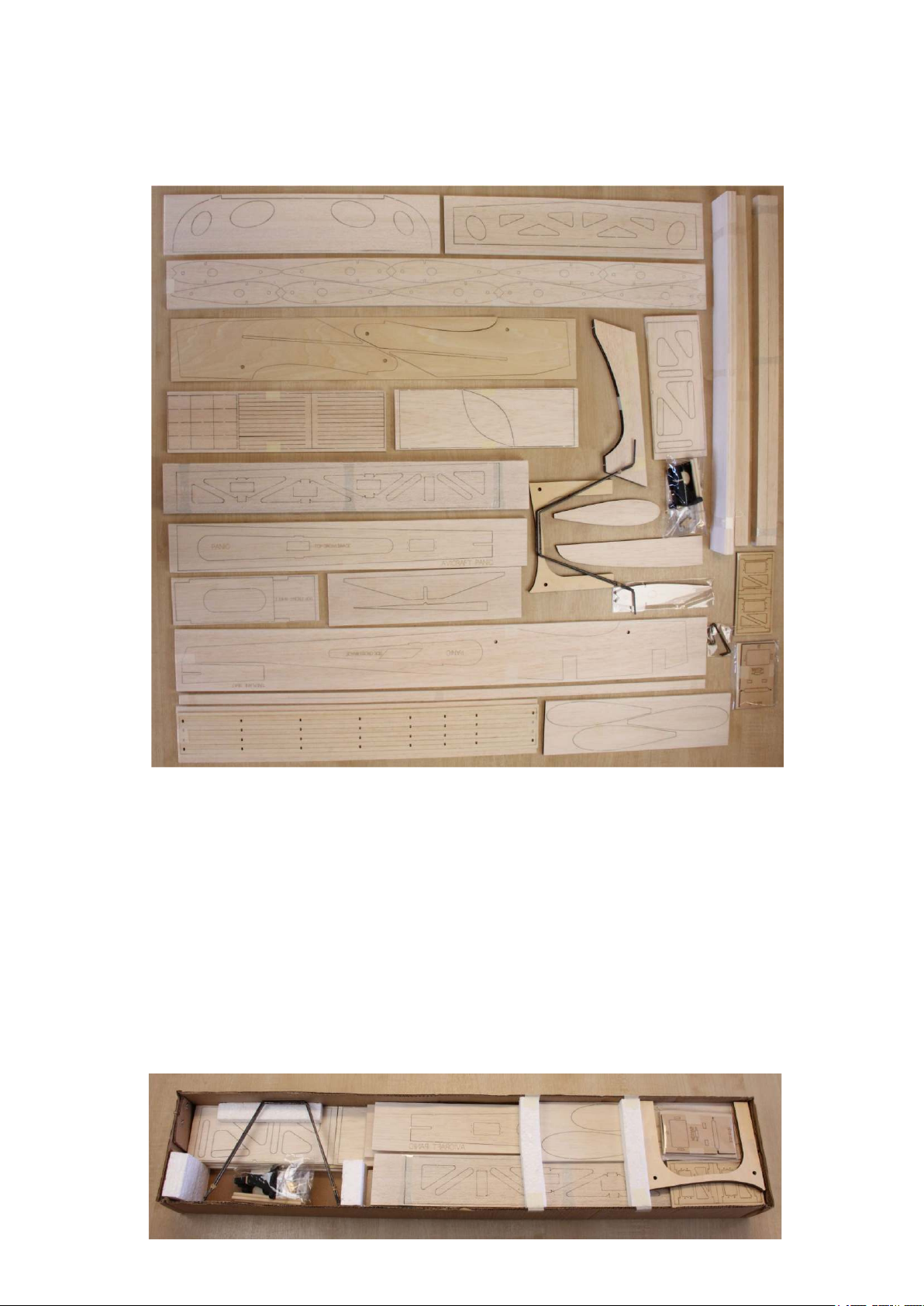
Please read the instrucon fully before commencing your build.
Kit contents:
The kit contains laser cut sheet ply and balsa parts and all the strip wood needed to complete the model. Also included
is the wire undercarriage ready to solder, press-studs, wing dowels, undercarriage saddle clamps and engine mount.
Check all components against the packing list to familiarise yourself with each part.
Addional items required are:
Glue, radio equipment, wheels and collets, aileron, elevator, rudder horns, push-rod linkages, closed loop rudder system,
control surface hinges x 23, brass tube O/D 8-10mm for undercarriage, servo extension leads, iron-on covering film and
propulsion system of your choice.
Assembly Instrucons
Note: Most joints can be made by the popular method of fing or holding parts together and wicking a very
small amount of thin cyanoacrylate glue (cyano) between them. A strong and lightweight build may be
achieved in this way. Be warned however that this makes an instant and permanent bond, so be sure that
things are right before you apply the glue. Note also that cyano, especially the thin variety, tends to soak into
and harden balsa, This can make subsequent carving and sanding more difficult, and for this reason some
modellers prefer using a soer “white” glue for certain jobs.
Page 3
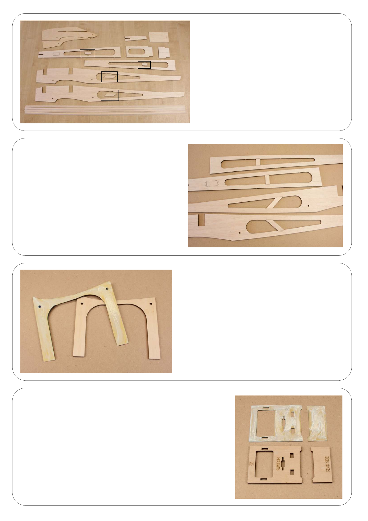
Glue in place the reinforcing strips on the
fuselage sides and the top and boom frames.
Allow to dry and then sand.
Remove the excess wood from the fuselage
frames ensuring you keep the reinforcing
strips highlighted in the image.
Prepare the four ply centre cabanes. Glue two of
the cabanes together as shown in the image, when
dry sand the edges but make sure you do not round
the edges. Repeat the process for the other two
pieces.
Prepare the two servo trays and glue together. Once dry sand
the sides square.
Page 4
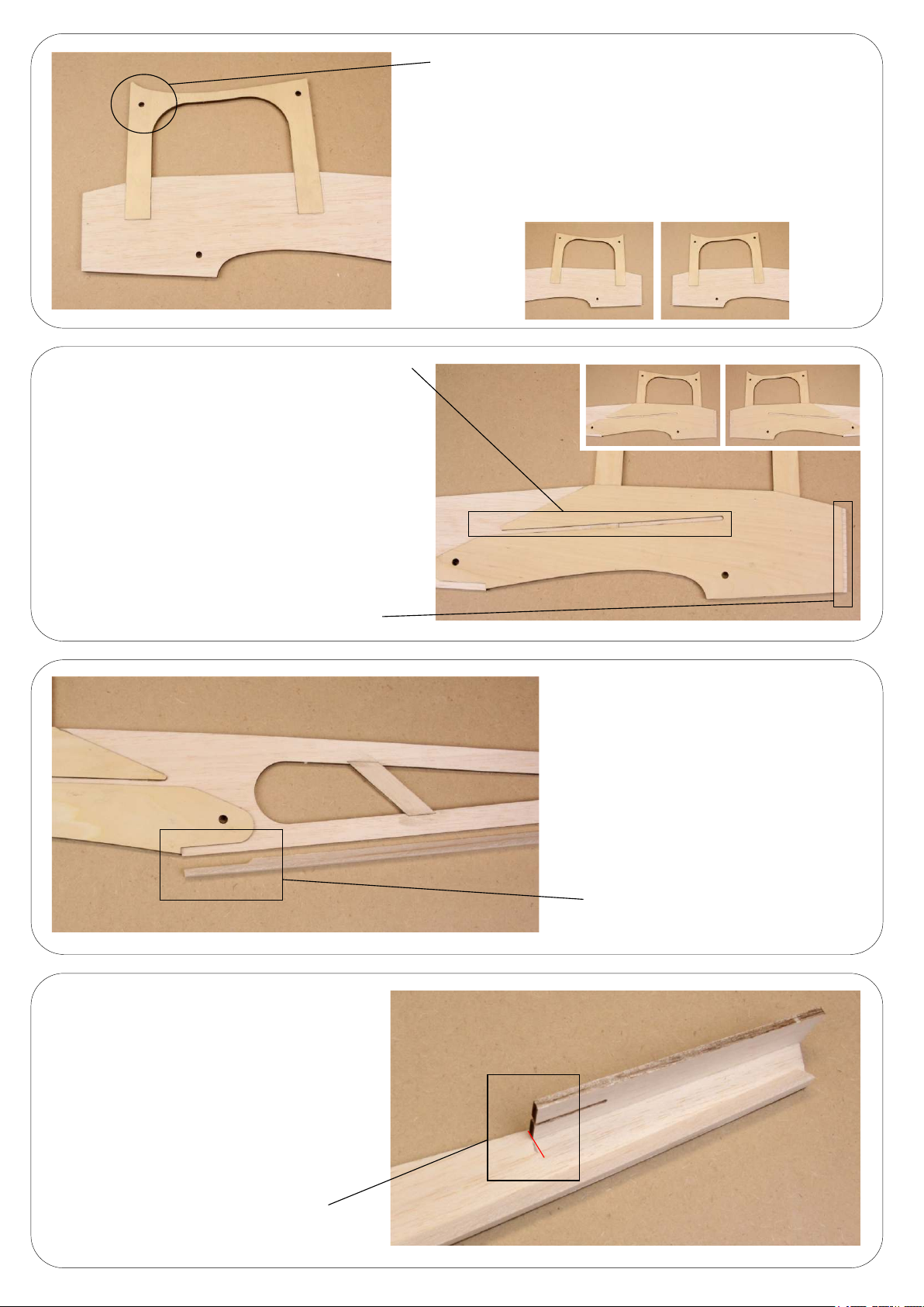
No glue in the servo tray channel.
NOTE - Please make sure you make the two
fuselage panel to suit the le and the right
(NOT THE SAME) Glue the ply re-enforcer to the
inside edge of the fuselage side. Use the dowel
holes as a reference point for alignment. When in
posion you should have enough space for the fire
wall to sit just in front of the reinforcing plate but be
flush to the external edge of the balsa fuselage at
the front. Also ensure the channel for the servo tray
does not fill with glue.
This must be to the front of the plane.
Glue the cabane to the fuselage ensuring the correct
orientaon (use image for reference). Allow to dry and sand
flush to the side you will be using for the port side of the
fuselage. Repeat the process and make sure on the second
one you sand the fuselage the opposite side to the first
(starboard).
Gap for the firewall.
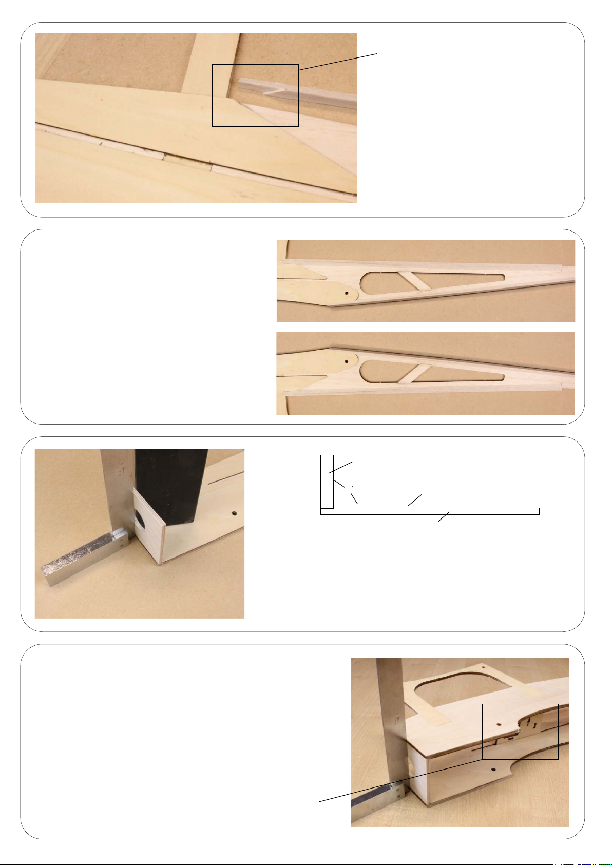
Place the tailplane seat in posion and mark
the forward most point on the fuselage side.
This is to prevent the triangle secon going
any further than this point.
Using the four lengths of triangle secon
cut to length a secon to travel from the
rear wing seat area to the rear of the
fuselage. You will need to make a slight
cut as shown in the image to allow to lay
flat.
Make a small cut to allow to lay flat.
Mark this posion.
Page 5
The rear of the fuselage should look like this.
Repeat the process on the other fuselage
frame but to suit the opposite side.
Trim to allow the triangle secon to lay flat.
Repeattheprocessasperthebottom
sectionoftrianglestrip.Remembertorun
thetrianglesectiontothepositionyou
markedjustinfrontofthetailplaneseat.
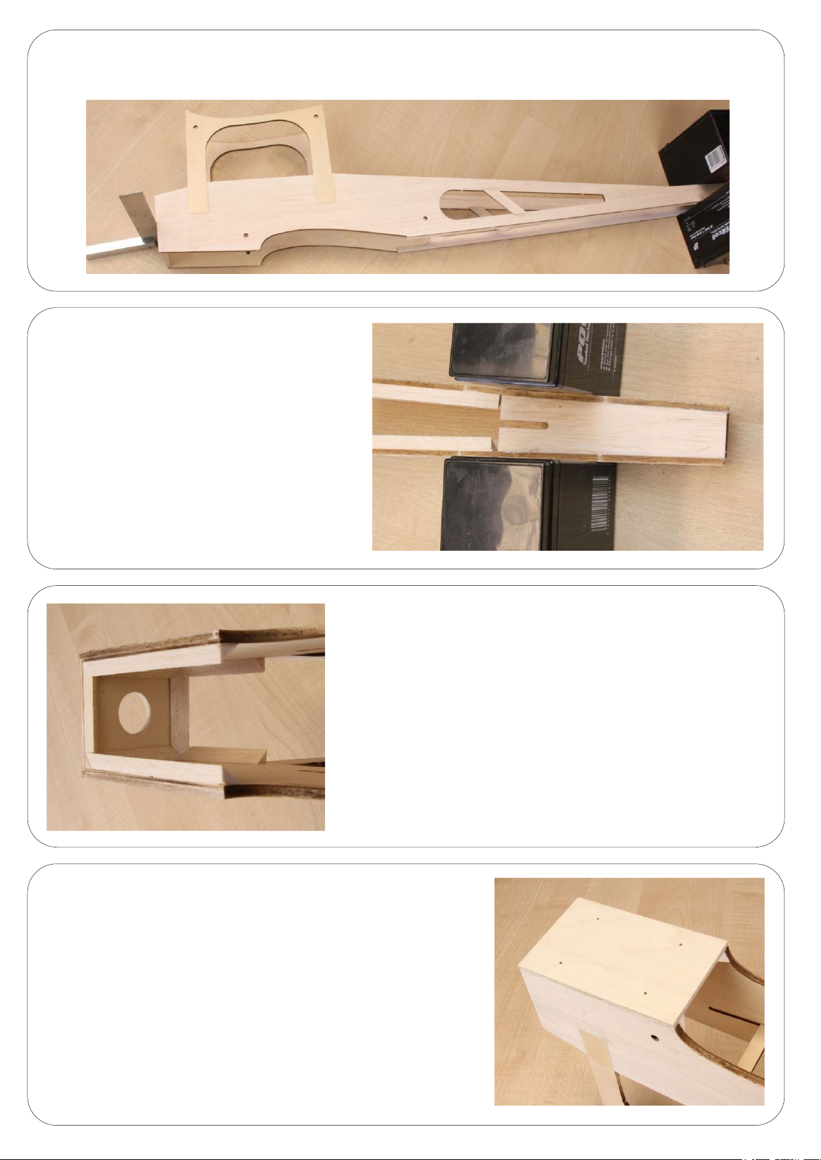
Glue the firewall in place in the recess createdbythereinforcing
plyandthefrontedgeofthefuselageframe.Itisimperativethis
isgluedintheverticalpositionandallowedtodry.
Note: please use image on next page in conjuncon with
this step.
Glue the other side of the fuselage in place at the firewall only.
Use the servo tray as a temporary spacer to keep the fuselage
frames parallel but do not glue the servo tray in posion.
Firewall
90
Pywood re-enforcing
Balsa fuselage frame
Use servo tray as a spacer(do not glue in place).
Page 6
While gluing the two sides to the firewall make sure you keep the two frames parallel to each other.
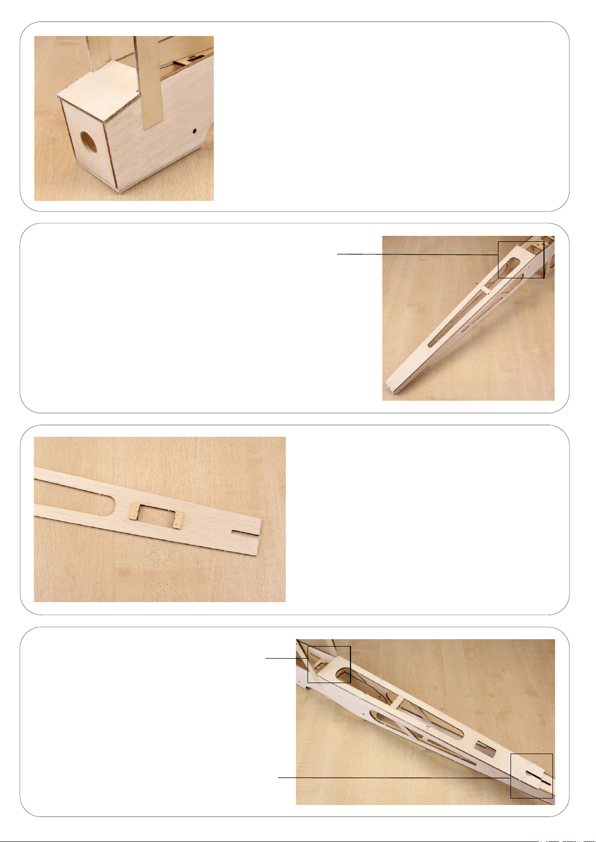
Insert the tailplane seat between the two fuselage
frames and glue in place. It is very important when
you glue this in place that you do not induce a
banana shape to the fuselage.
Glue in place the undercarriage plate.
With the remaining triangle secon re-enforce the
firewall, undercarriage plate and top plate.
Page 7
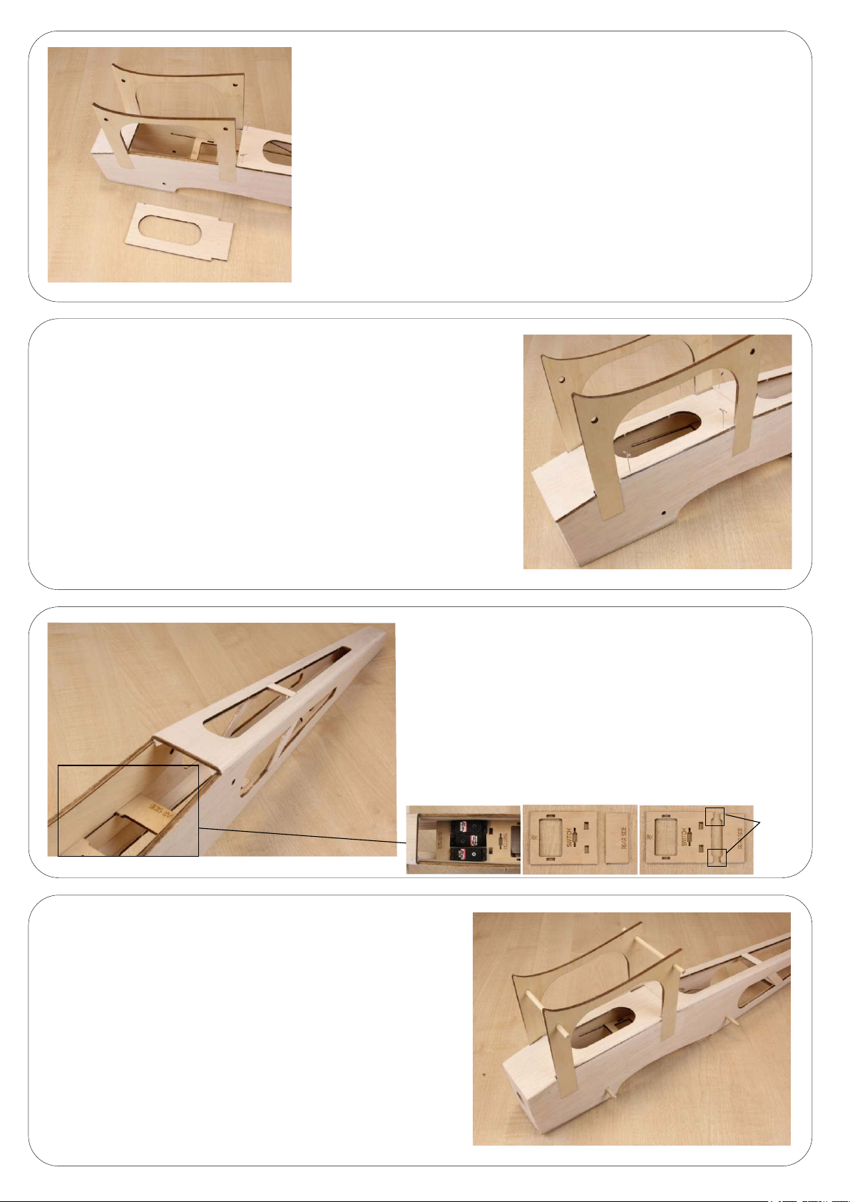
Glue in place the top plate ensuring it aligns with the
centre cabanes.
Ensure the frame aligns perfectly
with rear wing seang area
Glue the underside frame in place. Ensure the frame aligns
perfectly with the rear trailing edge wing seang area.
Ensure the frame bus up
to the rear of the cabanes.
Glue the top frame in place ensuring the fin post
cut out aligns to the tailplane seat and the frame
bus up to the rear of the cabanes.
Ensure the fin post cut out
aligns with the cut out in the
tailplane plate .
Before gluing the top frame in place you need to decide
if the rudder servo will be located at the rear or inside the
fuselage. If your choice is at the rear please install the
servo blocks on the inside of the frame. If your choice is
inside then please use a piece of scrap balsa to blank the
servo hole.
Page 8
Before glueing the centre top plate in place a decision needs to be
made. If your intenons for this Panic are to go electric now is the
me to fabricate a tray system and hatch for your baery.
If you have chosen to go for the IC setup then
please glue the top plate in place.
Insert the dowels supplied to the centre cabane and
the lower fuselage.
Now the fuselage is complete sand all edges and round
the rear fuselage corners. How much you round the rear
of the fuselage is up to you but weight can be saved by
increasing the radiuses. You can now glue the servo tray
in place making sure the rear of the tray aligns with the
reinforcing edge. Make sure you leave adequate space
between the two servo trays to fit your servos. If you have
chosen to put the rudder servo inside the fuselage and
you are installing a throle servo you will need to remove
the parts shown in the image below.
Remove
Page 9
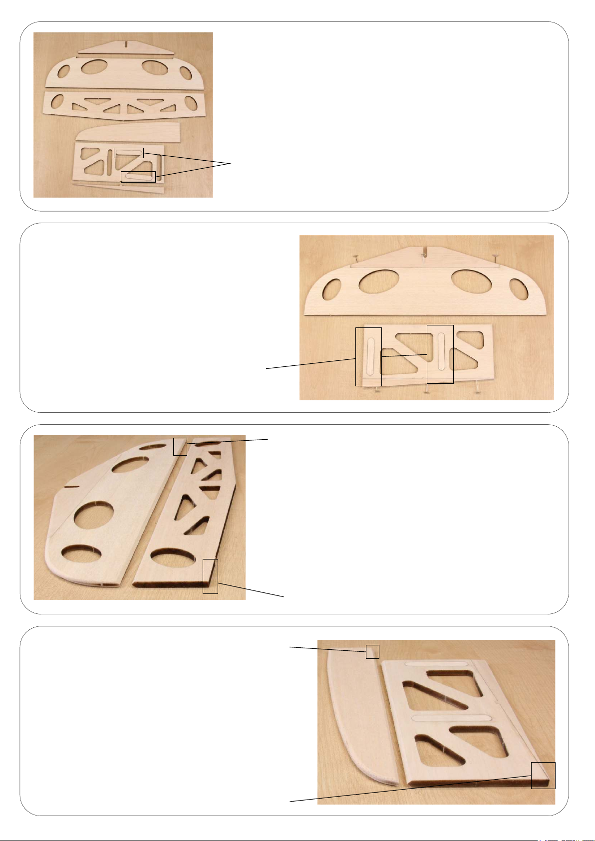
Remove all excess balsa from the tailplane and fin. Please make sure
you keep the two secons highlighted in the image.
Keep these two reinforcing strips.
On a flat surface glue the leading edge on the front
of the tailplane and glue the trailing edge of the
rudder to the rudder. Insert the reinforcing into
the rudder.
Glue the reinforcing strips in place.
Do not round trailing edge. Either sand flat or V shape.
Sand the tailplane flat and round the leading edge as shown
in the image. The trailing edge of the tailplane you can either
leave flat or you can shape to a V which aids extreme movement.
Under no circumstances round the trailing edge of the tailplane
as it restricts movement of the elevator. The elevator will need
to be V-shaped on the leading edge and the trailing edge needs
to be le flat. Do not round the trailing edge of the elevator as
this will make the control surface less effecve.
Do not round trailing edge. Either sand flat or V shape.
Sand the leading edge of the fin as shown in the image.
The trailing edge of the fin you can either leave flat or
you can shape to a V which aids extreme movement.
Under no circumstances round the trailing edge of the
fin as it restricts movement of the rudder. The rudder
will need to be V-shaped on the leading edge and the
trailing edge needs to be le flat. Do not round the
trailing edge of the rudder as this will make the
control surface less effecve.
Do not round trailing edge.
Do not round trailing edge.
Page 10
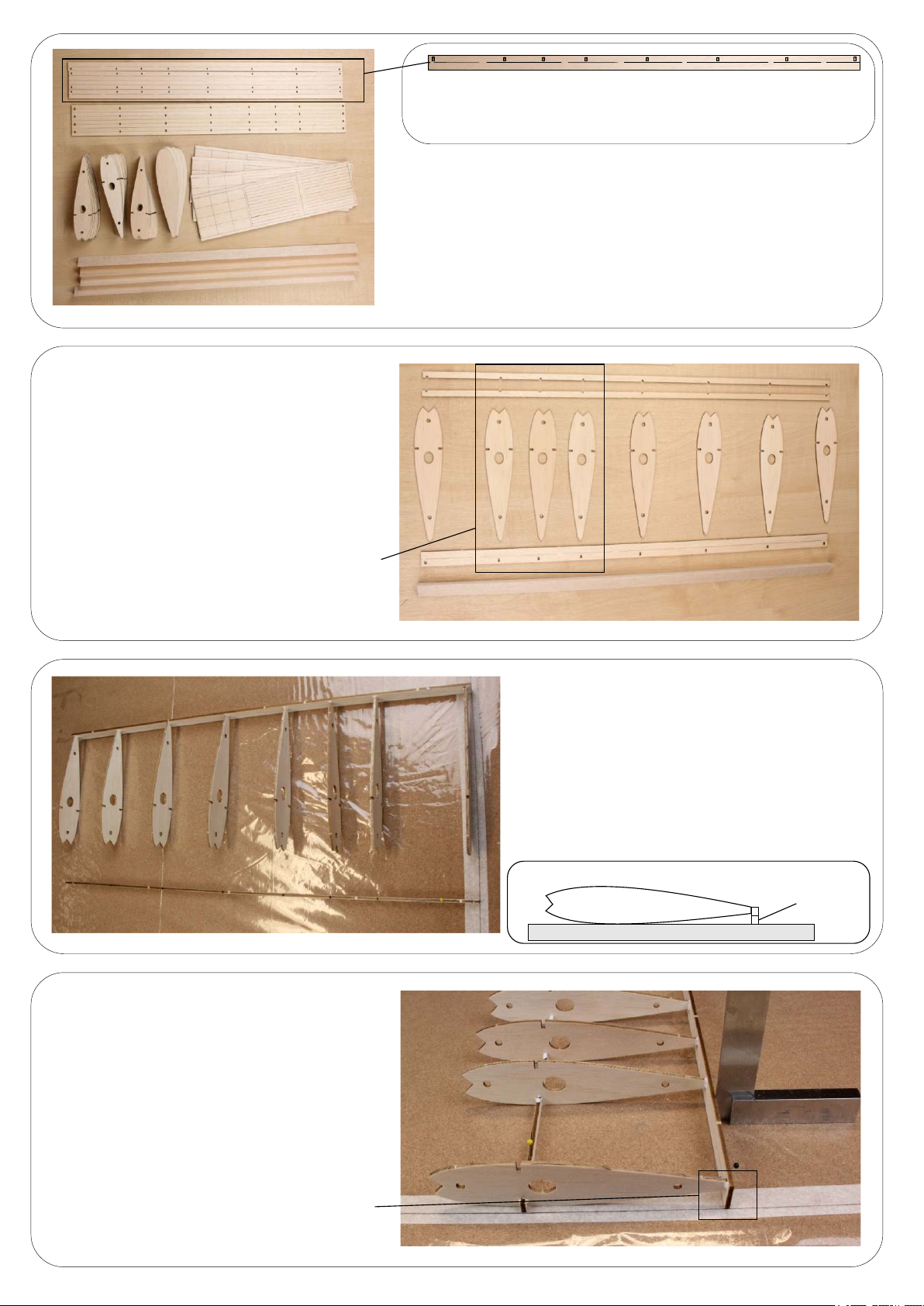
Lay out the necessary parts to build one wing
panel. This comprises of :–
1 x Triangle leading edge
1 x Trailing edge with build jig aached
2 x Top and boom strips
8 x Wing ribs
Separate the trailing edge strip as per the image above.
The lower part of this secon is used as a wing build jig,
but also used as part of the wing build later. Do no discard.
Remove all excess wood from the wing ribs and prepare items
as shown in the image. Please be careful not to split the trailing
edge strips as these have a strip aached to it for building the
wing on a flat surface.
IMPORTANT - Please note that the three ribs
that are grouped together should always form
part of the inboard wing as this area is for the
servo points.
We recommend you build the wing on a building
board so you can pin the trailing edge and wing ribs
square to each other. It is imperave the wing is
built square otherwise when you come to join the
wing panels together it will be hard to align the
wing panels. Before you pin the parts to the board
glue the ribs to the trailing edge strip using a slow
seng glue to allow working me.
Build jig
Glue the lower strip in place with a slow seng
glue to allow working me. Now place the wing
secon on your build board and pin in posion
making sure everything is square. At this point
you can see the importance of the trailing edge
build jig spacing the wing profile from the board.
Build jig spacing the trailing edge off
the build board.
Page 11
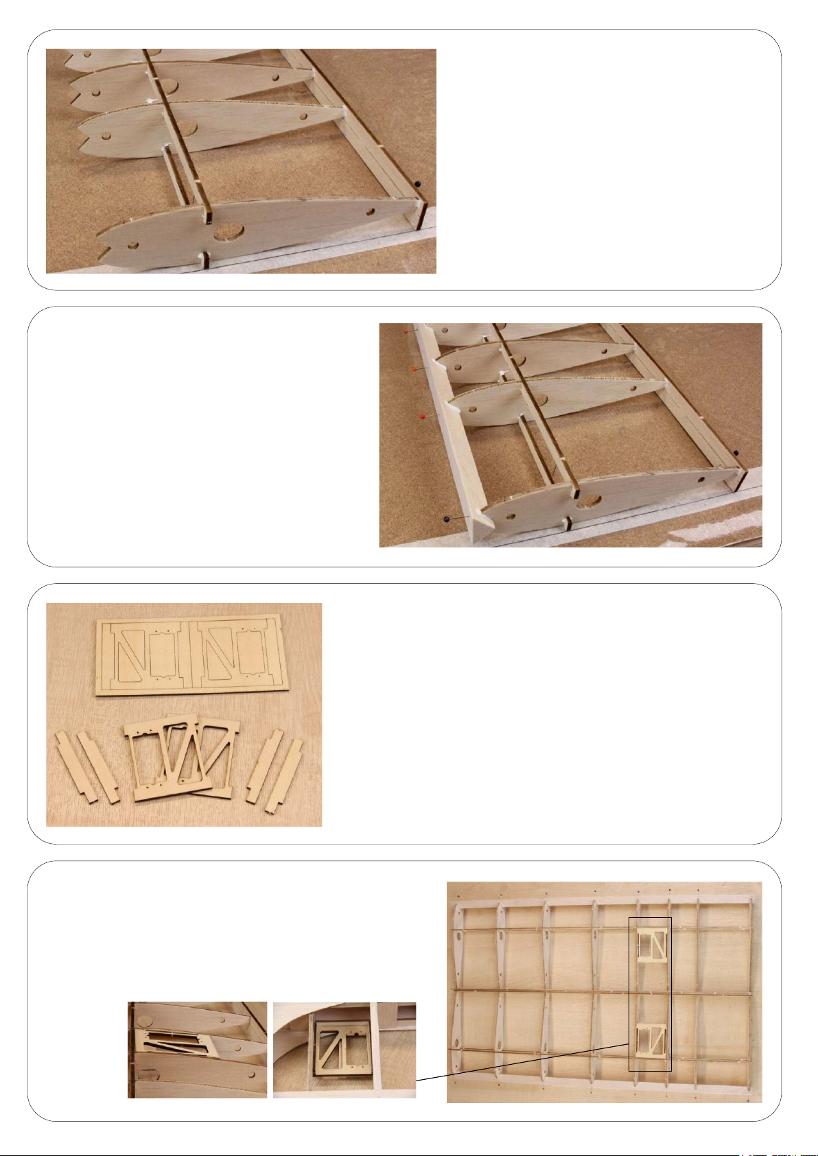
Glue and pin the triangle leading edge in place and
allow to dry.
Make sure the wing ribs are sing vercal
to the build board. As menoned before this is
imperave for when it comes to joining the wing
panels together.
Before starng on the servo trays you have to decide if you are
going to use four servos for ailerons or just two in the lower wing
with joiner rods to the top ailerons. Remove the excess plywood
from the servo trays and ensure the surfaces are clean.
Glue the servo trays in place as shown.
IMPORTANT – it is imperave the servo tray fits between the
ribs on the outboard side of the three ribs that are posioned
closer than the rest. Also it is imperave that the servo tray is
flush with the surface of the rib, if set deeper into the rib the
servo will protrude past the surface of the wing on the reverse
side when installed.
Outboard wing
Inboard wing
Servo trays must be in this posion.
Page 12
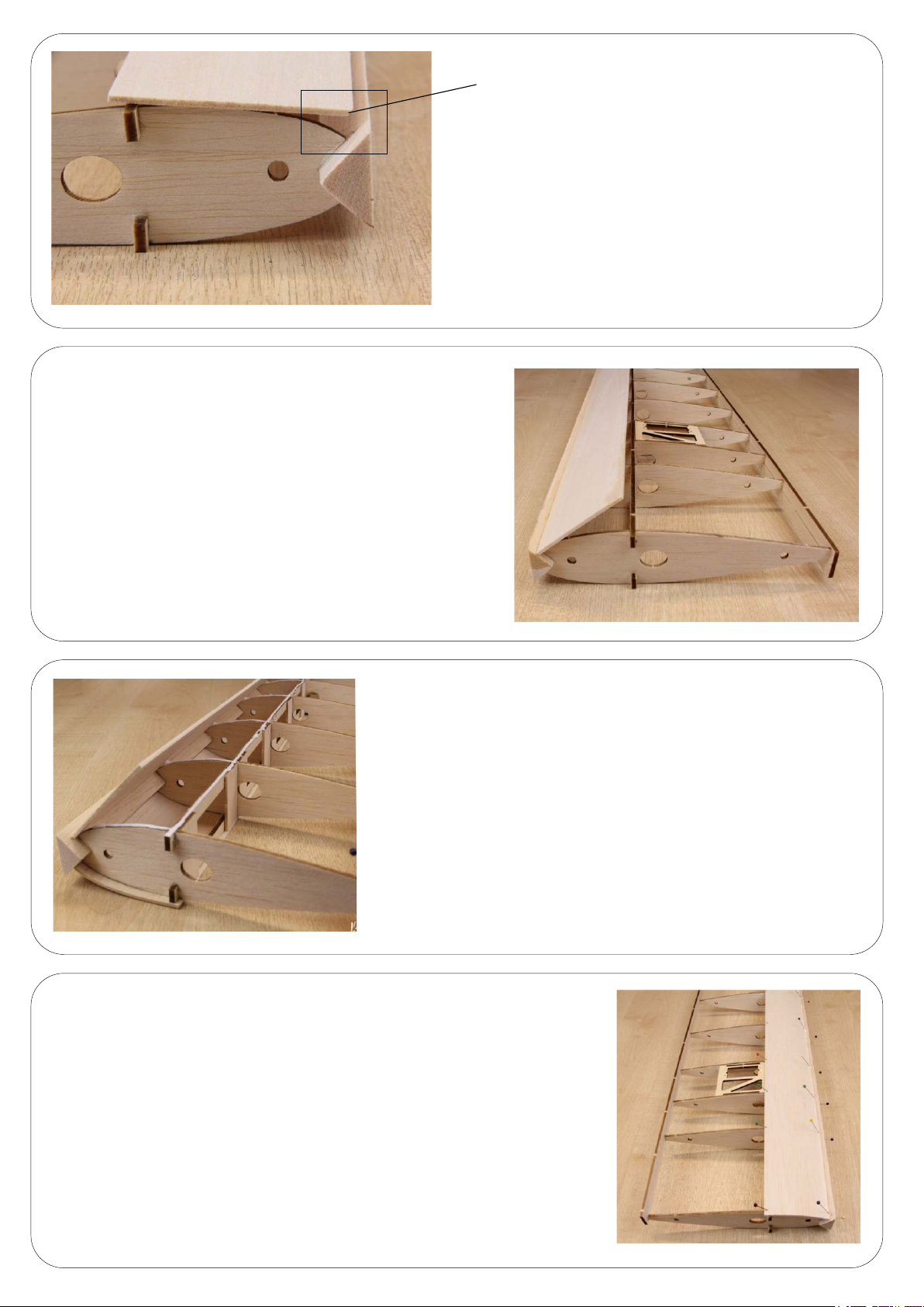
Glue the sheet in place and leave to dry in this posion.
Do not aempt to roll the balsa sheet back into posion
unl fully dry.
Angle the secon to allow for a good
surface contact to the triangle leading edge.
Obtain one of the eight sheets of leading edge sheeng.
The leading edge of the sheet you need to slightly chamfer
the edge so it aligns with the triangle leading edge when
glued in place.
When the glue has set on the leading edge run slow seng glue
on the ribs.
Carefully pull the balsa sheet back over the front of the ribs and pin in place
and allow to dry. Repeat the process on the reverse side.
Page 13
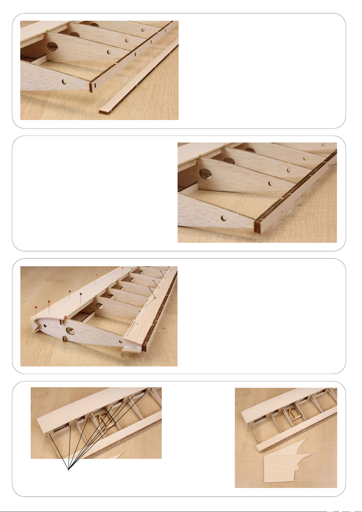
Now glue the jig strip on the back of the trailing
edge as shown and pin in place.
Carefully remove the trailing edge jig strip and sand
the trailing edge to ensure it is flat.
Install the reinforcing strips as shown in the image
along the length of the wing.
Obtain one of the eight trailing edge strips and glue in
place as per the image and repeat the process on the
reverse side.
Remove the excess
balsa from two of
the eight centre balsa
sheets as shown in the
image.
Page 14
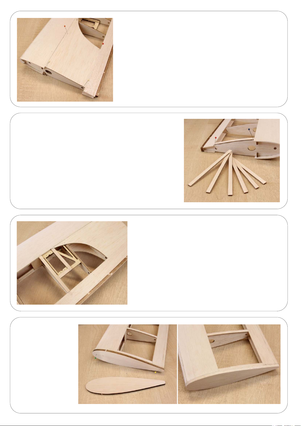
Glue the centre balsa sheet in place cung it at the trailing edge to fit
the gap between the front and rear sheet. Please note this is to be
aached to the inboard wing area closest to the servo tray which should
always be inboard of the wing NOT outboard. Remove the excess balsa
from the wing rib capping strips and cut to size and glue in place on both
the top side of the wing and boom.
Remove the excess balsa from the wing rib capping strips and cut
to size and glue in place on both the top side of the wing and boom.
Remove all excess wood
overhanging the wing ribs
on either end of the wing
and sand flat. Once
removed glue one of the
four wing ps in place.
IMPORTANT – Please make
sure this is glued on the
out board wingp.
Using the wing rib capping strip make a box area around the
servo tray as shown in the image.
Page 15
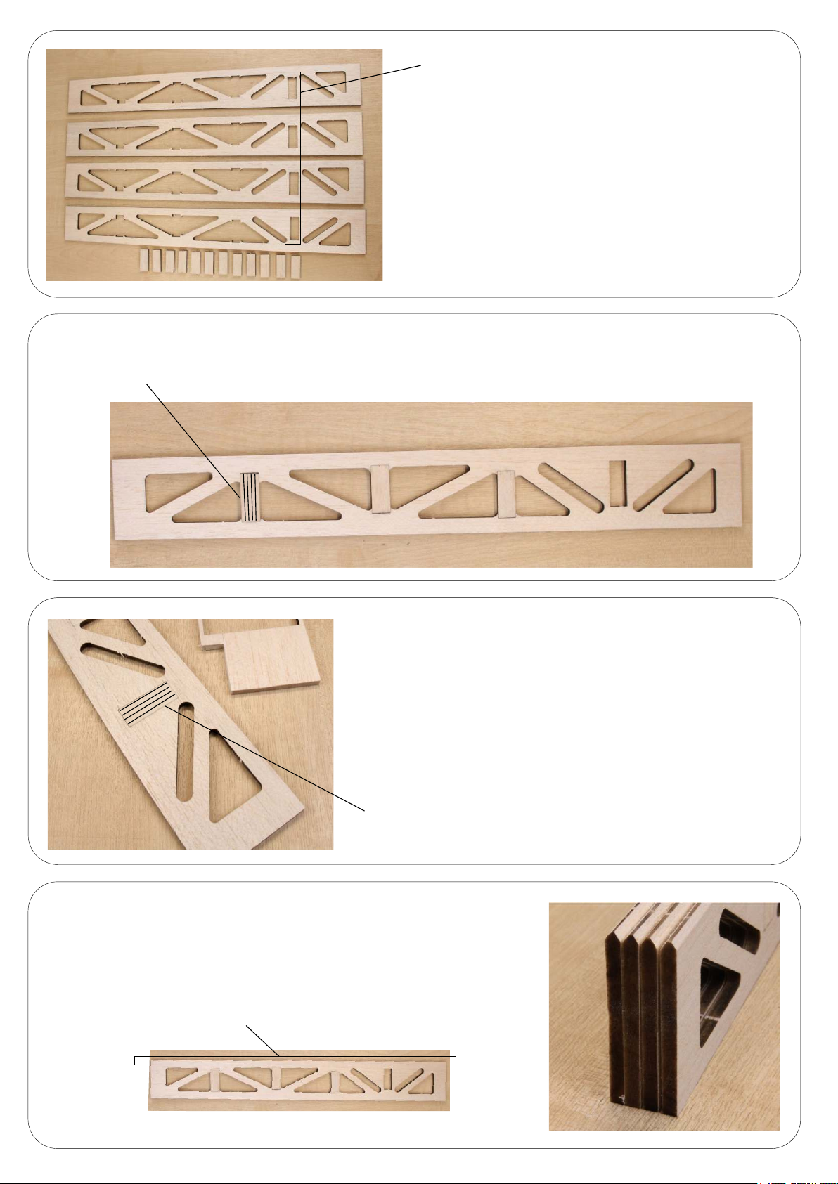
Glue these into place as shown paying aenon to the grain direcon.
Grain direcon front to back.
Remove these and discard so not to get
confused with the others.
Remove the excess wood from the ailerons but keep the small
squares as shown in the image. Please discard the squares
removed from the highlighted points on the image so they are
not confused with the others as the grain direcon differs from
the two types. Also please keep the outer part of the aileron in
parcular the end secon.
Using the outer secon of the aileron that you kept from two
steps ago, cut a secon to fit the secon shown, nong the
grain direcon, and glue in place.
Grain direcon front to back.
Please V-shape the leading edge of the ailerons as shown in the image.
Pay aenon to the image below to show which side is the leading edge.
Leading edge of aileron.
Page 16
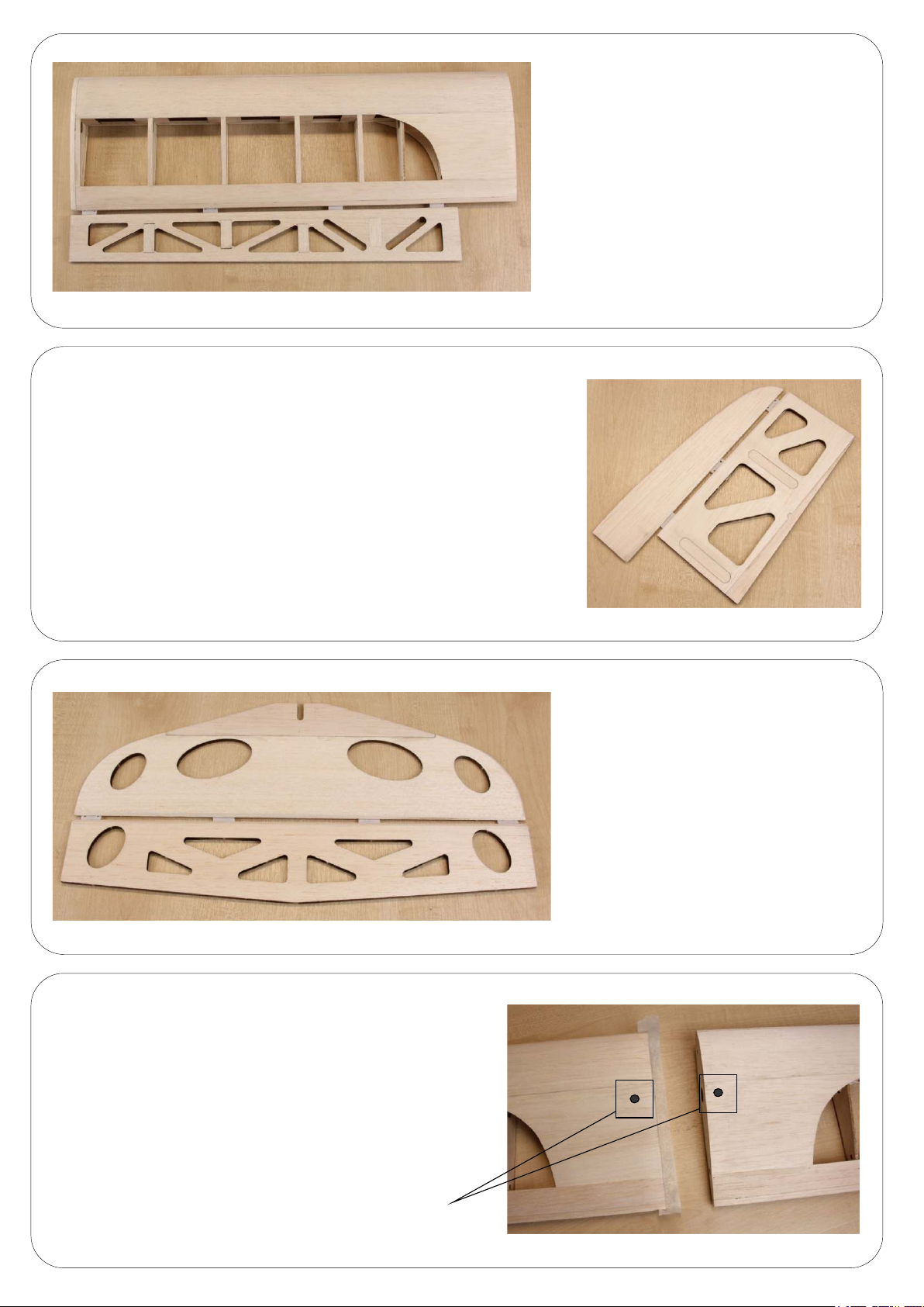
Please note this is for reference only for
posioning of the hinges as this is normally
done once the covering of your choice has
been applied. We recommend four hinges
per aileron. Hinges are not supplied in the kit.
Please note this is for reference only for posioning of the hinges as
this is normally done once the covering of your choice has been applied.
We recommend three hinges for the rudder. Hinges are not supplied
in the kit.
Prepare the four wing panels to be glued together.
Before you commence gluing you need to finalise
the exit points for your aileron servo leads so they
exit the wing inside the fuselage. Install some
drawstring to make it easy when it comes to
installing the servos. Run a secon of masking
tape around the lower part of the wing ready to
receive the other wing panel.
Please note this is for reference only for
posioning of the hinges as this is normally
done once the covering of your choice has
been applied. We recommend four hinges
for the elevator. Hinges are not supplied in
the kit.
Exit holes for servo leads.
Page 17
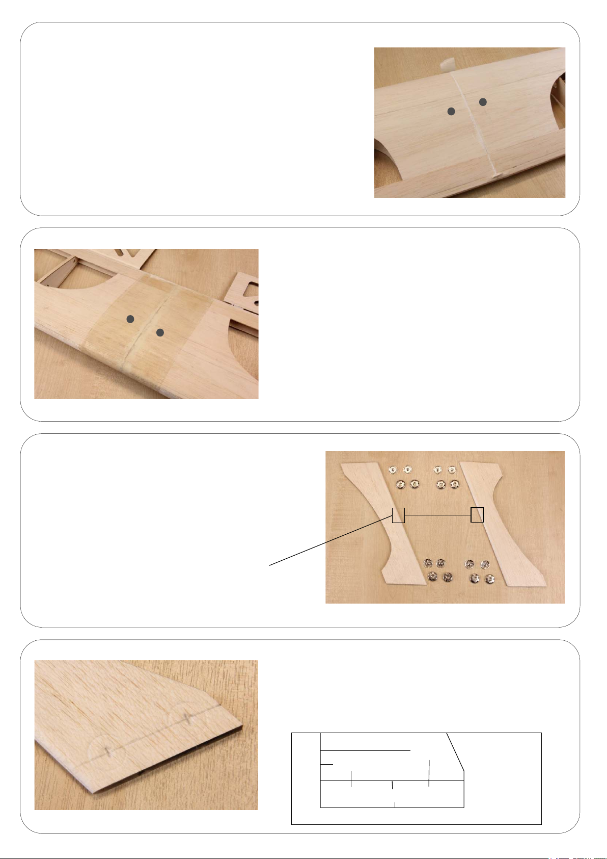
Apply the glue and push the two wing panels together, the masking tape
on the boom will prevent any glue seeping out from the boom. Whilst
drying the wing will need to be kept under constant pressure from
wingp to wingp so find some good weights to push the two wing
panels together.
Using glass cloth (not supplied) run a secon around the
centre wing secon and seal the wing. We recommend
ZAP finishing resin. Repeat the process with the other wing.
When dry cut out the holes for the servo leads.
Please round the leading edge of the wing p struts.
To secure the wing p struts use the 19mm press studs.
You will require eight pairs for the build.
Round the leading edges.
Mark a line 15mm in from either end of the wing strut.
Then measure from the leading edge of the strut back
20mm along that line. Then measure again from the
leading edge of the strut 60mm back. This is the
posion for the studs. When posions have been found
press the stud down to mark the outer ring.
60mm
20mm
Leading edge
15mm
Page 18
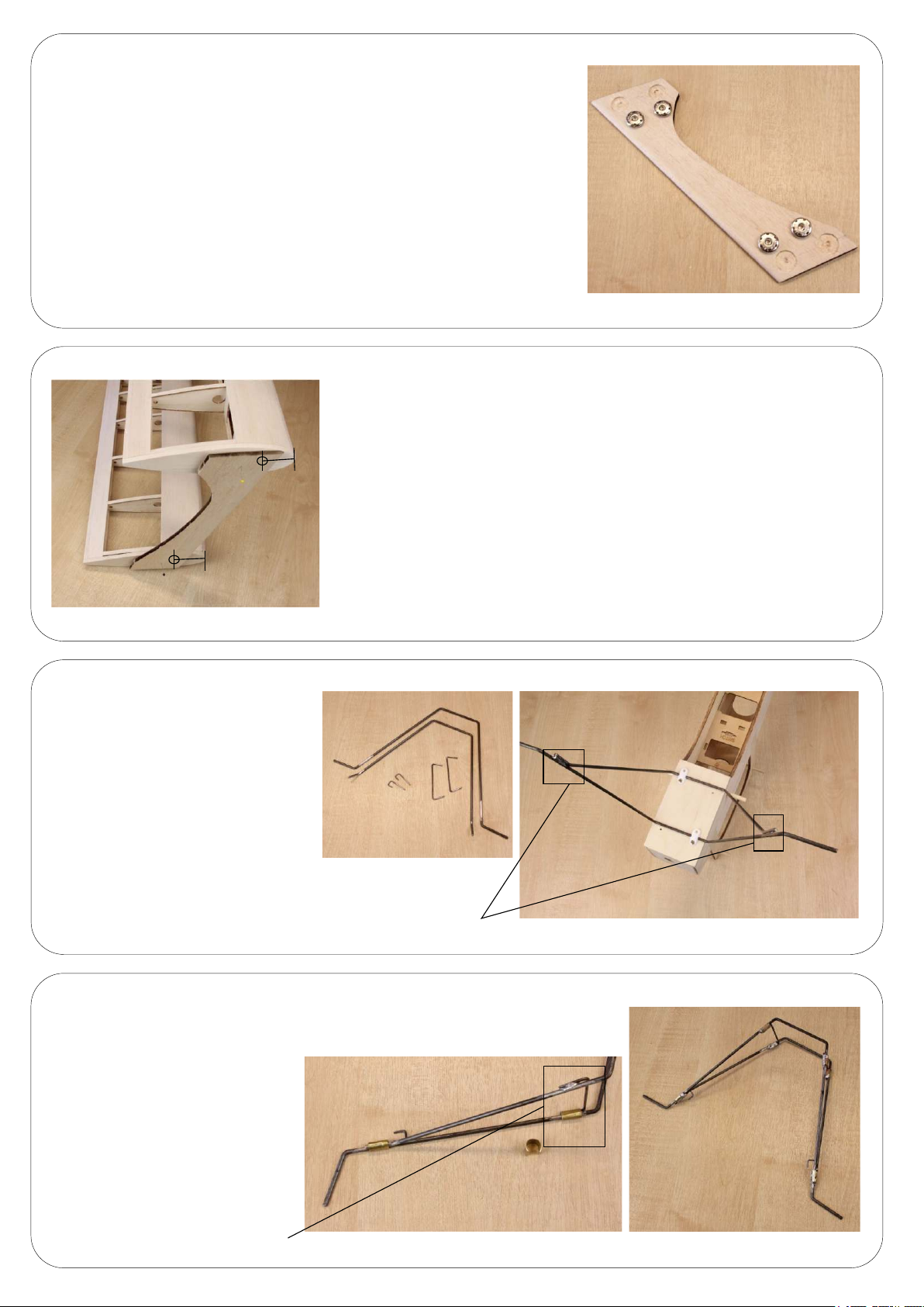
Recess the area of the stud about 3-4mm so the base can sit below the
surface of the strut which makes it easier to glue into place. Do not glue
the studs in place as it is easier to cover the strut first, then remove the
covering from the recessed areas and glue the studs in place. It will be
necessary to temporarily tack them in place to mark the posion on the
wing p studs.
50mm
50mm
Posion the undercarriage wire on
the plane as shown and mark the
joining posions of the wire. Remove
and clean all metal joints with a file.
Place back on the plane and temporary
solder the main undercarriage together.
Posion the wings on the plane and pin the strut to the top and boom so
the stud foremost is 50mm from the leading edge on both the top and the
boom. Repeat the same process on the other side. When you are happy
with the posioning of the struts gently press the strut against the wing p
to make an impression on the wing p so the press stud posion can be
located.
Solder these points temporally.
Posion the rubber band supports according to the metal length. If you have an
IC engine and have the silencer running under the fuselage it may be necessary
to lower this to allow the pipe to pass and not interfere with the rubber bands.
Cut 8 – 10mm diameter brass tube
and slit so it creates a C shape.
Wrap this round the joint and solder
in place. Once complete fit the
undercarriage with the supplied
saddle clamps.
This may need to be
lowered to allow for the pipe.
Page 19
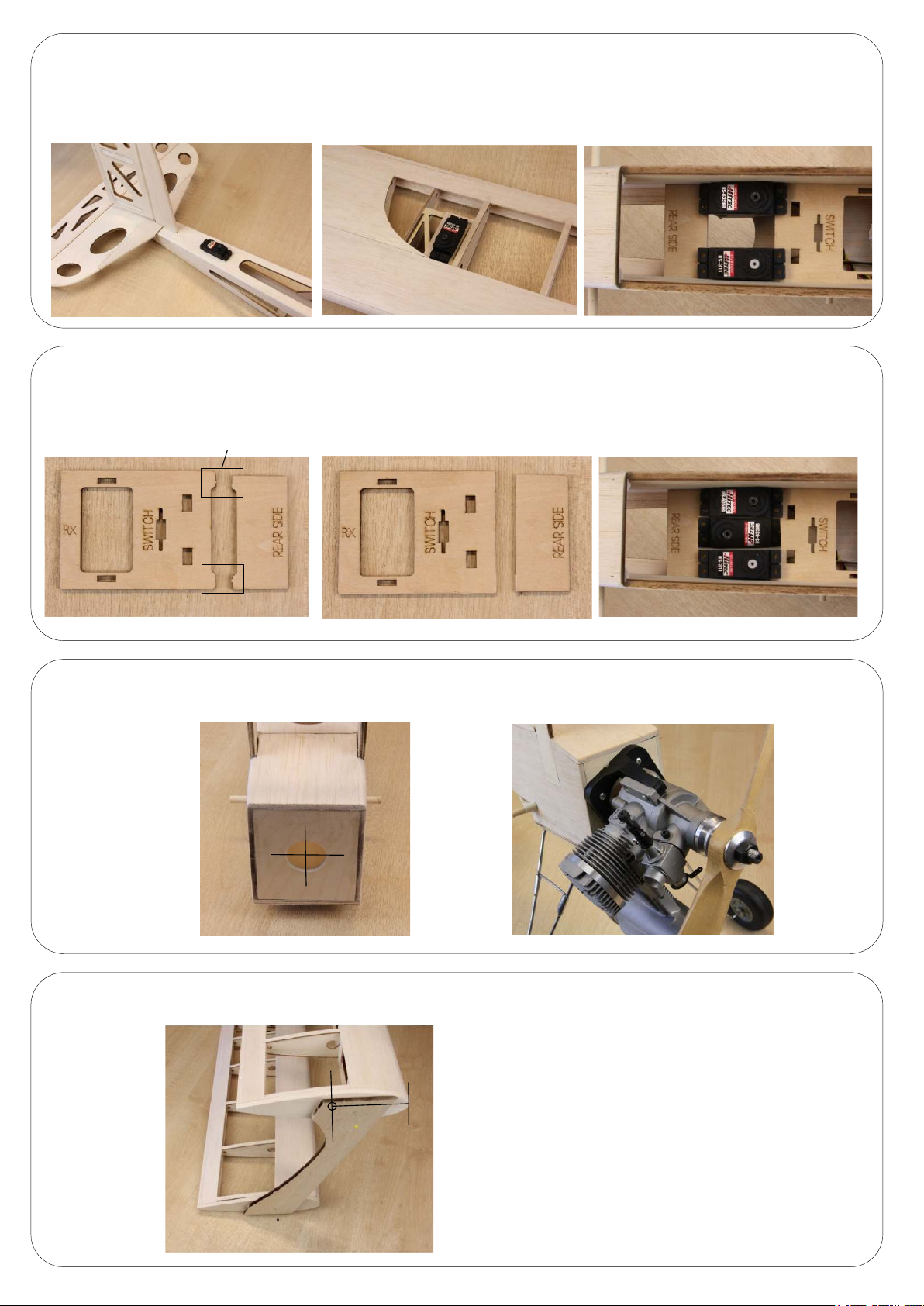
The most common servo installaon:-
2 x Servos on the lower wing for the ailerons with links to the upper wing ailerons.
1 x Rudder servo in the rear of the fuselage with closed loop control wire.
1 x Elevator servo in main servo tray.
1 x Throle servo in main servo tray.
If you have chosen to put the rudder servo in the main servo tray please ensure you modify the servo tray
before installaon.
Remove before tray installaon.
The line of thrust on the Panic is centred around the hole in the firewall, Any power system you are installing
please use this as the centre of your installaon.
With the panic covered and everything installed the C.O.G will need to be checked. This should be 100mm from
the leading edge of the top wing.
Control movement
100mm
Experienced pilots
Aileron. 25mm (1”) each way.
Elevator. 40mm (1” 5/8) each way.
Rudder. Up to 80 degrees each way
Not quite so experienced pilots
Aileron. 15mm (1/2”) each way.
Elevator. 20mm (3/4”) each way.
Rudder. Up to 50mm (2”) each way
Page 20

 Loading...