

AVIC TMS190WX1-22TC Specification
Global LCD Panel Exchange Center
www.panelook.com
One step solution for LCD / PDP / OLED panel application: Datasheet, inventory and accessory!
www.panelook.com
FRQILGHQWLDO
.............................
....................................................
MODULE TMS190MODULE TMS19
N ............
Global LCD Panel Exchange Center
www.panelook.com
TM-SA-A0020-01-E 2/25
CONTENTS
CONTENTS ....................................................................................................................................................................2
1. OUTLINE....................................................................................................................................................................3
1.1 STRUCTURE AND PRINCIPLE.................................................................................................................3
1.2 APPLICATIONS...........................................................................................................................................3
1.3 FEATURES...................................................................................................................................................3
2. GENERAL INFORMATION ......................................................................................................................................4
3. BLOCK DIAGRAM˄FOR REFERENCE˅ ............................................................................................................5
4. DETAILED SPECIFIC
4.1 MECHANICAL SPECIFICATIONS ............................................................................................................6
4.2 ABSOLUTE MAXIMUM RATINGS...........................................................................................................6
4.3 ELECTRICAL CHARACTERISTICS.........................................................................................................7
4.4 POWER SUPPLY VOLTAGE SEQUENCE AND RIPPLE .........................................................................8
4.5 INTERFACE AND CONNECTOR PIN ALIGNMENT.............................................................................10
ATION....................................................................................................................................6
4.6 LVDS I/F DATA CHART ............................................................................................................................11
4.7 DISPLAY COLORS AND INPUT DATA SIGNALS.................................................................................12
4.8 INTERFACE TIMING................................................................................................................................13
4.9 OPTICS (BASED ON TFT LCD MODULE TMS190WX1-19TB˅............................................................16
5. MARKINGSˈPACKING, TRANSPORTATION AND DELIVERY ......................................................................20
5.1 PRODUCT LABEL ....................................................................................................................................20
5.2 PACKING ...................................................................................................................................................21
5.3 INSPECTION RECORD SHEET...............................................................................................................21
5.4 TRANSPORTATION..................................................................................................................................21
5.5 SIZE AND WEIGHT FOR PACKING BOX..............................................................................................21
5.6 OUTLINE FIGURE FOR PACKING (For reference)................................................................................22
6.PRECAUTIONS.........................................................................................................................................................23
6.1 ASSEMBLY AND HANDLING PRECAUTIONS ....................................................................................23
6.2 OTHER....................................................................................................................................................................23
7. OUTDRAWING........................................................................................................................................................24
Not duplication without authorization Shanghai AVIC OPTOELECTRONICS Co., Ltd.
One step solution for LCD / PDP / OLED panel application: Datasheet, inventory and accessory!
www.panelook.com
FRQILGHQWLDO
+:(1,440×900 p
1000:
(Ton+T
(Ton+T
Global LCD Panel Exchange Center
www.panelook.com
TM-SA-A0020-01-E 3/25
1. OUTLINE
1.1 STRUCTURE AND PRINCIPLE
TMS190WX1-22TC open cell is composed of the amorphous silicon thin film transistor liquid crystal display
(a-Si TFT LCD) panel structure with driver LSIs for driving the TFT (Thin Film Transistor) array.
The a-Si TFT LCD panel structure is injected liquid crystal material into a narrow gap between the TFT array
glass substrate and a color-filter glass substrate.
Color (Red, Green, Blue) data signals from a host system (e.g. PC, signal generator, etc.) are modulated into best
form for active matrix system by a signal processing board, and sent to the driver LSIs which drive the individual TFT
arrays.
The TFT array as an electro-optical switch regulates the amount of transmitted light from the backlight assembly,
when it is controlled by data signals. Color images are created by regulating the amount of transmitted light through
the TFT array of red, green and blue dots.
1.2 APPLICATIONS
• Monitor for PC
1.3 FEATURES
• a-Si TFT active matrix
• LVDS interface
• R.G.B input 8bit, 16.7 millions colors (6bit+Hi-FRC)
• Resolution WXGA+:(1,440×900 pixels)
• High contrast ratio 1000:1
• High response time (Ton+Toff=5 ms˅
Not duplication without authorization Shanghai AVIC OPTOELECTRONICS Co., Ltd.
One step solution for LCD / PDP / OLED panel application: Datasheet, inventory and accessory!
www.panelook.com
FRQILGHQWLDO
Global LCD Panel Exchange Center
www.panelook.com
2. GENERAL INFORMATION
Display area 408.24 (H) x 255.15 (V)mm (typ.), [48.0 cm (19.0 inches)]
Drive system a-Si TFT active matrix
Display color 16.7M colors (6bit+Hi-FRC)
Pixel 1,440 (H) x 900(V) pixels
Pixel arrangement RGB (Red dotǃGreen dotǃ Blue dot) vertical stripe
Pixel pitch 0.2835 (W) x 0.2835 (H) mm
Signal system
Power supply voltage LCD panel signal processing board˖5.0V
TM-SA-A0020-01-E 4/25
LVDS 2port
[ RGB :8-bit, Dot clock (CLK), Data enable (DE)]
5.0V
Not duplication without authorization Shanghai AVIC OPTOELECTRONICS Co., Ltd.
One step solution for LCD / PDP / OLED panel application: Datasheet, inventory and accessory!
www.panelook.com
˅
FRQILGHQWLDO
Global LCD Panel Exchange Center
www.panelook.com
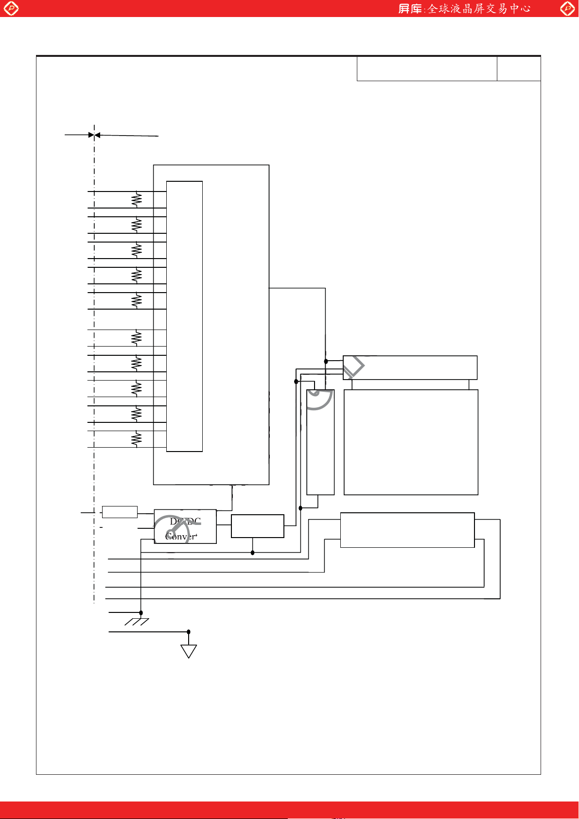
3. BLOCK DIAGRAM˄FOR REFERENCE
LCD MODULE I/F
DA0+
DA0-
DA1+
DA1-
DA2+
DA2-
CKA+
CKA-
DA3+
DA3-
DB0+
DB0-
DB1+
DB1-
DB2+
DB2-
CKB+
CKA-
DB3+
DB3-
100¡
Tming Controller
100¡
100¡
100¡
100¡
100¡
LVDS Receiver
100¡
100¡
100¡
100¡
TM-SA-A0020-01-E 5/25
Source Driver
4320 columns
Gate Driver
LCD Panel
900 rows
H:1440h3˄R,G,B˅
V:900
VDD
`
VBLH1/2
VBLH3/4
VBLC1/2
VBLC3/4
FG
Note: System ground(GND), FG (Frame ground) in the product should be connected together in customer
Not duplication without authorization Shanghai AVIC OPTOELECTRONICS Co., Ltd.
FUSE
equipment.
DC/DC
Power
Edge side backlight
One step solution for LCD / PDP / OLED panel application: Datasheet, inventory and accessory!
www.panelook.com
UnU
pFTopF
humidity Note4
Global LCD Panel Exchange Center
www.panelook.com
4. DETAILED SPECIFICATION
4.1 MECHANICAL SPECIFICATIONS
Parameter Specification Unit
Display area 408.24(H) x 255.15 (V) mm (typ.), [48.0 cm (19.0 inches)] mm
Display dot number 1440×3(H) ×900(V) -
Pixel pitch 0.2835(H)×0.2835(V) mm
Dot pitch 0.0945(H) ×0.2835(V) mm
Color arrangement RGB (Red dotǃGreen dotǃ Blue dot) vertical stripe -
Display color 16,777,216(6bit+Hi FRC) color
4.2 ABSOLUTE MAXIMUM RATINGS
TM-SA-A0020-01-E 6/25
Parameter Symbol Rating Unit Remarks
Power supply voltage VDD -0.3 ~+6.0 V Ta = 25°C
Input voltage for signals VI -0.3~3.3 V Ta = 25°C Note1
Storage temperature Tst -20 ~ +60 °C -
Front surface TopF 0 ~ +50 °C Note2
Operating temperature
Rear surface TopR 0 ~+55 °C Note3
Relative humidity Note4 RH
Absolute humidity Note4 AH İ1RWH g/m3 7D!e&
Operating altitude - İ m e&İ7Dİe&
Storage altitude - İ m e&İ7Dİe&
t
o
İ 7Dİe&
İ
%
e&7Dİe&
Note1: Display signals are DA0+/-, DA1+/-, DA2+/-, DA3+/-, CKA+/-, DB0+/-, DB1+/-, DB2+/-,
DB3+/-,and CKB+/-.
Note2: Measured at center of LCD panel surface (including self-heat)
Note3: Measured at center of LCD module's rear shield surface (including self-heat)
Note4: No condensation
Note5: Ta = 50°C, RH = 85%
Not duplication without authorization Shanghai AVIC OPTOELECTRONICS Co., Ltd.
One step solution for LCD / PDP / OLED panel application: Datasheet, inventory and accessory!
www.panelook.com
(
FRQILGHQWLDO
V
V
O
0/15 scalescale
1F
R33
MOSFET- NMOSFE
Global LCD Panel Exchange Center
www.panelook.com
TM-SA-A0020-01-E 7/25
4.3 ELECTRICAL CHARACTERISTICS
4.3.1 Driving for LCD panel signal processing board
Parameter Symbol min. typ. max. Unit Remarks
Power supply voltage VDD 4.5 5.0 5.5 V -
Power supply current IDD - 450 Note1
Permissible ripple voltage VRP - - 150 mV VDD
Differential input threshold
voltage for LVDS receiver
Low VTL -100 - - mV
High VTH - - +100 mV
Input voltage width for LVDS receiver VI 0 - 3.3 V -
Rush current +TWUJ
- - 3.0 A
Note1: Checked flag pattern (EIAJ ED-2522)
Note2: Pattern for maximum current˄2H1V dot inverse, 0/15 scale˅
Note3: Common mode voltage for LVDS driver
Note4:
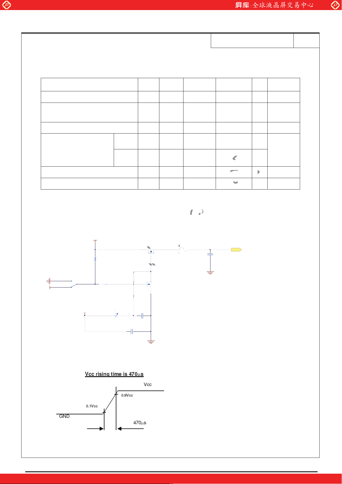
Measurement Conditions:
5V
R1
47K
Q1
1
MOSFET- N
F1
F
Fuse ( 2A )
650 Note2
C1
Cap
1uF/16V
VDD
Ta=25°C)
mA
at VDD =
0V
5.
at VCM =
1.2V
Note3
Note4
GND
S2
1
2
5V
3
SW- SPD T
12V
R2
1K
K
R3
20K
C3
Cap
10uF/16V
C2
Cap
1uF/16V
Q2
MOSFET -N
GND
GND
Not duplication without authorization Shanghai AVIC OPTOELECTRONICS Co., Ltd.
One step solution for LCD / PDP / OLED panel application: Datasheet, inventory and accessory!
www.panelook.com
FRQILGHQWLDO
t
than 4.5V, a protectthan 4.5V, a protect
y signals of
again, it might
is on,
Global LCD Panel Exchange Center
www.panelook.com
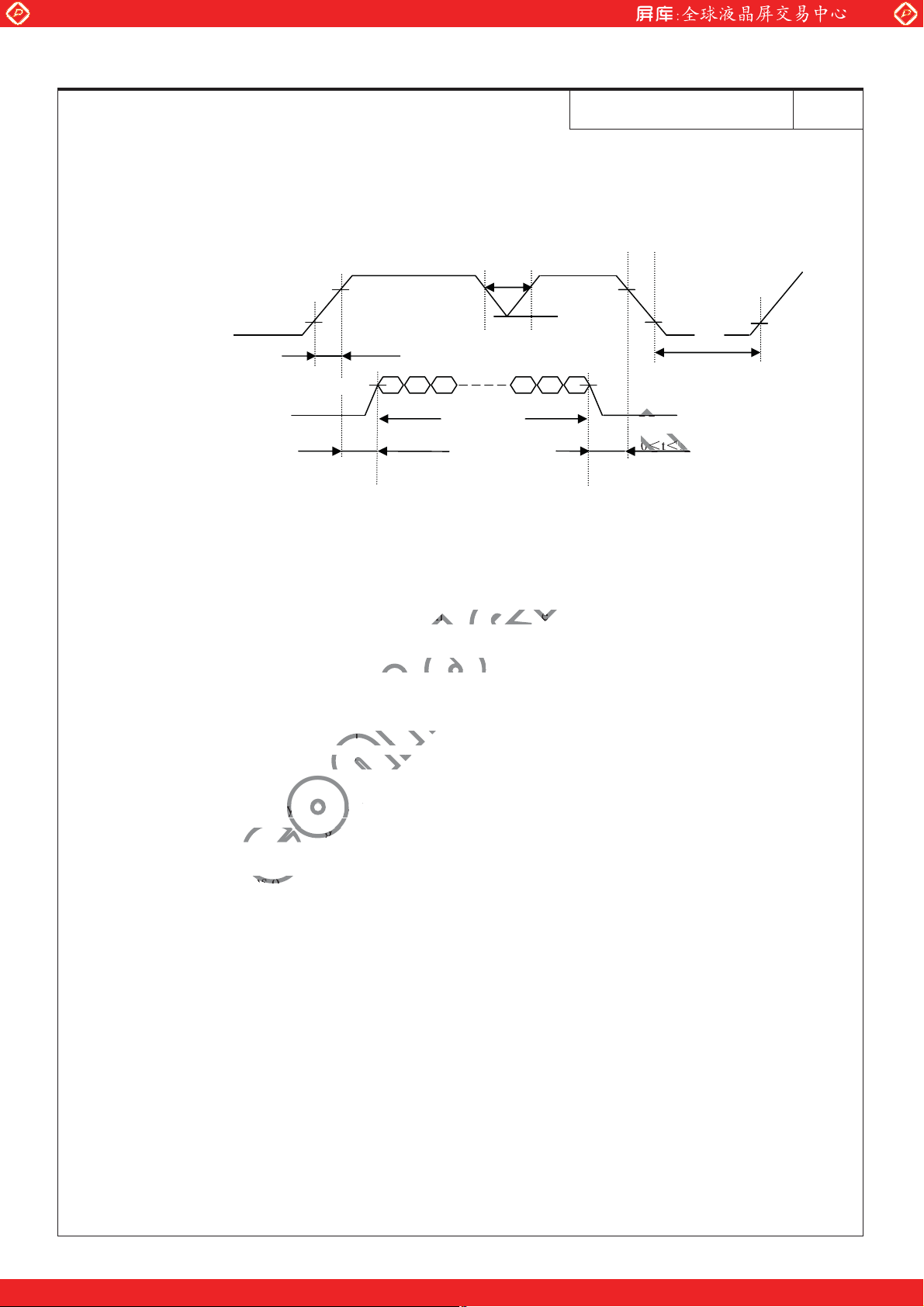
4.4 POWER SUPPLY VOLTAGE SEQUENCE AND RIPPLE
4.4.1 Power supply voltage sequence
t˘10ms * 1
VA L I D
VDD
Display Signals *2
0V
ON
90%
10%
0.47ms˘Tr˘10ms
90%
0V
0.5˘t˘50ms
4.5V
4.0V
TM-SA-A0020-01-E 8/25
90%
10%
90%
Toff ˚1000ms
0˘t˘50ms
10%
*1. When VDD is on, but the value is lower than 4.5V, a protection circuit may work, then the module may
not display.
*2 The signal line is not connected with the module, at the end of cable the terminal resistor of 100 should
be added.
Note1: Display signals (D0+/-, D1+/-, D2+/-, D3+/- and CK+/-) must be “0” voltage, exclude the VALID
period (See above sequence diagram). If these signals are higher than 0.3 V, the internal circuit is
damaged.
If some of display signals of this product are cut while this product is working, even if the signal input
to it once again, it might not work normally. If customer stops the display signals, they should cut
VDD.
Note2: When VDD is on, it should be set above 4.0V.
Not duplication without authorization Shanghai AVIC OPTOELECTRONICS Co., Ltd.
One step solution for LCD / PDP / OLED panel application: Datasheet, inventory and accessory!
www.panelook.com
 Loading...