

Aviation Communications and Surveillance Systems MSS25 User Manual
DRAFT 3-2
LYNX TM
Multilink Surveillance System
NGT-2000/2500
Part Number 9022500-10000
Installation Manual
This manual contains installation instructions and
recommended flightline maintenance information for
the NGT-2000/2500 Multilink Surveillance System
and Configuration Module. Guidelines for external
equipment necessary for installation are included.
This information is supplemented and kept current by
revisions, service letters and service bulletins.
0040-17011-01 (Revision A)
Prel-2014

DRAFT 3-2
Foreword
This manual provides information intended for use by persons who, in accordance with current regulatory
requirements, are qualified to install this equipment. Installation requirements may vary, depending on the
particularities of each aircraft, and this manual is intended as a guideline for that purpose. This manual
assumes familiarity with the setup and operation of the aircraft systems that interface with the NGT2000/2500.
If further information is required, please contact:
L-3 Avionics Systems
Attn: Field Service Engineering
5353 52
Grand Rapids, MI USA 49512-9704
Telephone: (800) 453-0288 or (616) 949-6600
Fax: (616) 977-6898
We welcome your comments concerning this manual. Although every effort has been made to keep it free
of errors, some may occur. When reporting a specific problem, please describe it briefly and include the
manual part number, the paragraph/figure/table number, and the page number. Send your comments to:
L-3 Avionics Systems
Attn: Technical Publications
5353 52
Grand Rapids, MI USA 49512-9704
Telephone: (800) 453-0288 or (616) 949-6600
Fax: (616) 977-6898
nd
Street, S.E.
nd
Street, S.E.
WARNING
INFORMATION SUBJECT TO EXPORT CONTROL LAWS
This technical data is controlled under the Export Administration
Regulations (EAR) and may not be exported without proper authorization
by the U.S. Department of Commerce.
Copyright 2014
L-3 Avionics Systems
Trademarks
Lynx
TM
is a trademark of L-3 Avionics Systems
Patent Pending
Page A 0040-17011-01
Prel-2014 Revision A

NGT-2000/2500
DRAFT 3-2
Installation Manual
ABOUT THIS MANUAL
SECTION 1 – GENERAL INFORMATION
This section provides the following information: unit configurations, unit functionality, items
required but not supplied with the unit, equipment specifications, installation approval/limitations
and TSO approvals.
SECTION 2 - INSTALLATION
This section contains instructions to locate, assemble and install the NGT-2000/2500 as well as
information for unpacking equipment, and inspection procedure for in-shipment damage.
SECTION 3 – INSTALLATION CHECKOUT
This section contains instructions for post installation setup, post installation and return to service
checkout.
SECTION 4 – MAINTENANCE
This section contains general flightline maintenance procedures. It includes periodic maintenance,
troubleshooting and instructions for the return of defective components.
APPENDIX A – SIGNAL AND CABLE CHARACTERISTICS
This appendix defines the electrical characteristics of all input and output signals.
APPENDIX B – ENVIRONMENTAL QUALIFICATION FORM
This appendix provides the environmental qualification test data.
Descriptions for Warnings, Cautions and Notes described below.
WARNING
Used to give notice to or call one's attention to beforehand especially of
danger (such as a warning to a Flight Crew person or a warning to a
mechanic before performing a dangerous task).
CAUTION
Statement that expresses the need for heightened awareness to conditions
that can cause damage to equipment.
NOTE
Used to point out a procedure, event or practice that it is desirable to
highlight.
0040-17011-01 Page i
Revision A Prel-2014

NGT-2000/2500
DRAFT 3-2
Installation Manual
References
Publication Description
0040-17010-01 Pilot's Guide for the NGT-2000/2500
0040-17020-01 Pilots guide for the CP-2500 Control Panel
0040-17021-01 Installation Manual for the CP-2500 Control Panel
Page ii 0040-17011-01
Prel-2014 Revision A

NGT-2000/2500
Revision A...................................... Prel-2014
Total number of pages in this publication consists of the following:
A Page
DRAFT 3-2
Installation Manual
List of Effective Pages
Dates of original and changed pages are:
Disclaimer
Information in this manual is subject to change without notice and will not be updated after distribution.
Changes to this manual will be reflected in the next revision. Revisions replace the entire manual and are
incorporated as needed in order to keep information accurate and up-to-date.
Avionics Systems does provide a listing of all publications and directives with their current revision to
insure up-to-date information. See www.as.l-3com.com to get an up-to-date listing of all Avionics
Systems technical publications and directives. Contact Avionics Systems Customer Care [1-616-9496600] to determine availability of technical publications and directives.
Title page
i thru x
1-1 thru 1-22
2-1 thru 2-20
3-1 thru 3-20
4-1 thru 4-12
A-1 thru A-22
B-1 thru B-2
0040-17011-01 Page iii
Revision A Prel-2014

NGT-2000/2500
DRAFT 3-2
Installation Manual
Table of Contents
Paragraph Page
Foreword ....................................................................................................................................................... A
About This Manual ......................................................................................................................................... i
References ..................................................................................................................................................... ii
List of Effective Pages ................................................................................................................................... iii
Table of Contents .......................................................................................................................................... iv
List of Illustrations ........................................................................................................................................ vii
List of Tables ............................................................................................................................................... viii
List of Abbreviations, Acronym and Symbols ................................................................................................ ix
SECTION 1
GENERAL INFORMATION
1.1 Introduction ................................................................................................................................. 1-1
1.2 Functional description................................................................................................................. 1-2
1.2.1 Enhanced Visual Acquisition Functional Overview .................................................................... 1-2
1.2.2 GPS Functional Overview .......................................................................................................... 1-2
1.2.3 FIS-B Functional Overview ......................................................................................................... 1-3
1.2.4 ADS-B Out Functional Overview ................................................................................................ 1-4
1.2.5 Multiple Source Inputs Operation ............................................................................................... 1-4
1.2.6 Discrete Inputs and Outputs ....................................................................................................... 1-4
1.2.7 Transponder Interface ................................................................................................................ 1-5
1.3 Equipment Descriptions.............................................................................................................. 1-5
1.3.1 System Product Key ................................................................................................................... 1-7
1.3.2 Data Configuration Module ......................................................................................................... 1-7
1.4 Specifications ............................................................................................................................. 1-8
1.5 TSO Information ....................................................................................................................... 1-10
1.5.1 TSO Markings ........................................................................................................................... 1-10
1.5.2 TSO Deviations from Minimum Performance Standards ......................................................... 1-11
1.5.3 Non-TSO Functions .................................................................................................................. 1-11
1.6 modifications ............................................................................................................................. 1-12
1.7 software Revisions ................................................................................................................... 1-12
1.8 interfaces .................................................................................................................................. 1-12
1.9 Equipment Required Not Supplied ........................................................................................... 1-13
1.9.1 Installation Kits ......................................................................................................................... 1-15
1.9.2 Antenna Cables ........................................................................................................................ 1-16
1.10 Equipment Interfaces ................................................................................................................ 1-17
1.10.1 GPS Antenna ............................................................................................................................ 1-17
1.10.2 UAT Antenna ............................................................................................................................ 1-17
1.10.3 Traffic Displays ......................................................................................................................... 1-18
1.10.4 Weather Display ....................................................................................................................... 1-18
1.10.5 Control Panel ............................................................................................................................ 1-18
1.10.6 WIFI Accessory ........................................................................................................................ 1-18
1.10.7 PERSONAL ELECTRONIC DEVICE (PED) APPS .................................................................. 1-19
1.11 Software Updates ..................................................................................................................... 1-19
1.11.1 Website Download .................................................................................................................... 1-19
1.11.2 Compact Disc ........................................................................................................................... 1-21
1.12 installation approval and Limitations ........................................................................................ 1-21
Page iv 0040-17011-01
Prel-2014 Revision A

NGT-2000/2500
DRAFT 3-2
Installation Manual
Table of Contents (cont.)
Paragraph Page
Section 2
Installation
2.1 Introduction ................................................................................................................................. 2-1
2.2 Unpacking and Inspecting .......................................................................................................... 2-1
2.2.1 Transport and Storage Considerations ...................................................................................... 2-1
2.3 Installation Procedures ............................................................................................................... 2-2
2.3.1 Location ...................................................................................................................................... 2-2
2.3.2 Antenna Installation Guidelines ................................................................................................ 2-14
2.3.3 NGT-2000/2500 Installation ..................................................................................................... 2-17
2.3.4 Remove and Replacement Procedures ................................................................................... 2-17
Section 3
Installation Checkout
3.1 Introduction ................................................................................................................................. 3-1
3.2 Maintenance PC ......................................................................................................................... 3-2
3.3 Configure WIFI Accessory .......................................................................................................... 3-3
3.4 Verify Software Version .............................................................................................................. 3-4
3.5 Select Configuration Options ...................................................................................................... 3-5
3.5.1 Aircraft Options ........................................................................................................................... 3-5
3.5.2 Altitude Options .......................................................................................................................... 3-7
3.5.3 Config Settings 1 ........................................................................................................................ 3-8
3.5.4 Config Settings 3 ........................................................................................................................ 3-9
3.5.5 RS-422/RS-232 Options ........................................................................................................... 3-10
3.5.6 Backup ...................................................................................................................................... 3-11
3.5.7 Clear Fault Log ......................................................................................................................... 3-11
3.6 Upgrade Model ......................................................................................................................... 3-12
3.7 Installation CHECKOUT ........................................................................................................... 3-13
3.7.1 Functional Check ...................................................................................................................... 3-14
3.7.2 GPS Operation Check .............................................................................................................. 3-16
3.7.3 ADS-B Out Check ..................................................................................................................... 3-17
3.7.4 ADS-B In Check ....................................................................................................................... 3-17
3.7.5 TIS-B Traffic Check .................................................................................................................. 3-18
3.7.6 Electromagnetic Interference (E.M.I.) Check ........................................................................... 3-19
3.7.7 Flight Test ................................................................................................................................. 3-20
3.7.8 Installation Checkout Complete ................................................................................................ 3-20
Section 4
Maintenance
4.1
Introduction ................................................................................................................................. 4-1
4.2 Continued airworthiness ............................................................................................................. 4-1
4.2.1 Periodic Maintenance ................................................................................................................. 4-1
4.3 Fault ISOLATION ....................................................................................................................... 4-2
4.4 Using the Maintenance PC ......................................................................................................... 4-7
4.4.1 Load Software ............................................................................................................................ 4-7
4.4.2 View or Retrieve Data ................................................................................................................. 4-8
4.4.4 Service ........................................................................................................................................ 4-9
4.5 return to Service ....................................................................................................................... 4-10
4.5.1 NGT-2000/2500 ........................................................................................................................ 4-10
4.5.2 Configuration Module ............................................................................................................... 4-11
4.5.3 L-Band (UAT) Antenna ............................................................................................................. 4-11
4.5.4 GPS Antenna ............................................................................................................................ 4-11
4.6 disposition of failed items ......................................................................................................... 4-12
0040-17011-01 Page v
Revision A Prel-2014

NGT-2000/2500
DRAFT 3-2
Installation Manual
Table of Contents (cont.)
Paragraph Page
Appendix A
NGT-2000/2500 Interface Signal Name & Cable Characteristics
A.1 Introduction .................................................................................................................................A-1
A.2 Input and Output Interfaces ........................................................................................................A-1
A.2.1 Input Power ................................................................................................................................A-1
A.2.2 I2C Serial Bus (Configuration Module) ........................................................................................A-1
A.2.3 RF Suppression Bus ...................................................................................................................A-1
A.2.4 Gillham Input (Altitude Input) ......................................................................................................A-1
A.2.5 ARINC 429 Output ......................................................................................................................A-2
A.2.6 Discrete Input .............................................................................................................................A-2
A.2.7 Discrete Output ...........................................................................................................................A-3
A.2.8 RS-422 Interface ........................................................................................................................A-3
A.2.9 RS-232 Interface ........................................................................................................................A-3
A.3 Pin Definition Summary ..............................................................................................................A-4
A.4 connector [J2] .............................................................................................................................A-5
Appendix B
Environmental Qualification Form
B.1 Introduction .................................................................................................................................B-1
B.2 Environmental Qualification Form ..............................................................................................B-1
Appendix C
Configuration and Checkout Log
Page vi 0040-17011-01
Prel-2014 Revision A

NGT-2000/2500
DRAFT 3-2
Installation Manual
List of Illustrations
Figure Page
Figure 1-1: System Interface Overview ...................................................................................................... 1-3
Figure 1-2: NGT-2000 Block Diagram ....................................................................................................... 1-6
Figure 1-3: NGT-2500 Block Diagram ....................................................................................................... 1-7
Figure 2-1: Outline Dimensions for NGT-2000/2500 ................................................................................. 2-3
Figure 2-2: NGT-2000/2500 Interconnect Wiring Diagram ........................................................................ 2-5
Figure 2-3: Mating Connector (P2) and Pin Assignments ......................................................................... 2-7
Figure 2-4: Outline Dimensions for the DCM ............................................................................................. 2-8
Figure 2-5: Mating Connector (P2) Cable Assembly ................................................................................. 2-9
Figure 2-6: Example of Antenna Mounting Locations .............................................................................. 2-14
Figure 3-1: NGT Maintenance Appliance Tool – Main Page ..................................................................... 3-2
Figure 3-2: NGT MAT – WiFi Accessory .................................................................................................... 3-3
Figure 3-3: NGT MAT – Check Versions .................................................................................................. 3-4
Figure 3-4: NGT MAT – Aircraft Options .................................................................................................... 3-5
Figure 3-5: NGT MAT – Altitude Options ................................................................................................... 3-7
Figure 3-6: NGT MAT-Config Settings 1 .................................................................................................... 3-8
Figure 3-7: NGT MAT - Config Settings 3 .................................................................................................. 3-9
Figure 3-8: NGT MAT - RS-422/RS-232 Options .................................................................................... 3-10
Figure 3-9: NGT MAT - Configuration Backup ......................................................................................... 3-11
Figure 3-10: NGT MAT –Fault Log .......................................................................................................... 3-11
Figure 3-11: NGT MAT – Upgrade Model ................................................................................................ 3-12
Figure 3-12: NGT MAT – Ground Test .................................................................................................... 3-14
Figure 3-13: NGT MAT – UAT GPS Status ............................................................................................. 3-14
Figure 3-14: NGT MAT – Live Data-GPS ................................................................................................ 3-16
Figure 4-1 Software Loading ...................................................................................................................... 4-7
Figure 4-2 NGT MAT- Information ............................................................................................................. 4-8
Figure 4-3: NGT MAT – Restore Configuration ......................................................................................... 4-9
Figure 4-4: NGT MAT – Service................................................................
................................................. 4-9
F
igure A-1: RN370M Interconnect Option for RS-232 to WiFi Converter ................................................. A-3
0040-17011-01 Page vii
Revision A Prel-2014

NGT-2000/2500
DRAFT 3-2
Installation Manual
List of Tables
Table Page
Table 1-1: NGT-2000/2500 General Description ....................................................................................... 1-1
Table 1-2: MSS Built-in Interfaces ............................................................................................................. 1-6
Table 1-3: Specifications for the NGT-2000 and NGT-2500 ...................................................................... 1-8
Table 1-4: Specifications for Configuration Module ................................................................................... 1-9
Table 1-5: Hardware Modifications .......................................................................................................... 1-12
Table 1-6: Software Revisions ................................................................................................................. 1-12
Table 1-7: Equipment List ........................................................................................................................ 1-13
Table 1-8: Installation Kit P/N 9060-17250-01 ......................................................................................... 1-15
Table 1-9: Coaxial Cable Specifications .................................................................................................. 1-16
Table 1-10: Approved GPS Antennas ...................................................................................................... 1-17
Table 1-11: Approved UAT Antennas ...................................................................................................... 1-17
Table 1-12: Approved Traffic Displays ..................................................................................................... 1-18
Table 1-13: Approved FIS-B WX Displays ............................................................................................... 1-18
Table 1-14: Approved Control Panels ...................................................................................................... 1-18
Table 1-15: Approved RS-232 to WiFi Accessories................................................................................. 1-18
Table 1-16: Compatible APPS for PED ................................................................................................... 1-19
Table 1-17: List of Service Notices .......................................................................................................... 1-20
Table 1-18: Software CD Part Number and Contents ............................................................................. 1-21
Table 2-1: Maximum UAT Antenna to Transponder Antenna Separation ............................................... 2-16
Table 4-1: Troubleshooting ........................................................................................................................ 4-2
Table A-1: Connector (P1) Pin Assignments ............................................................................................ A-4
Table C-1: Log Sheet for Configuration and Checkout ............................................................................. C-1
Page viii 0040-17011-01
Prel-2014 Revision A
NGT-2000/2500
DRAFT 3-2
Installation Manual
List of Abbreviations, Acronym and Symbols
ITEM DEFINITION
°
°C
°F
1090ES 1090 megahertz extended squitter
AC Advisory Circular
ACAS Airborne Collision Avoidance System
ACSS Aviation Communication and Surveillance Systems
ADC Air Data Computer
ADS-B Automatic Dependant Surveillance-Broadcast
ADS-R Automatic Dependent Surveillance Rebroadcast
AHRS Attitude & Heading Reference System
AIRB Basic Airborne Situation Awareness
EVaq Enhanced Visual Acquisition
AMLCD Active Matrix Liquid Crystal Display
AMM Aircraft Maintenance Manual
ARINC Aeronautical Radio, Incorporated
ASA Aircraft Surveillance Applications
ASSAP Airborne Surveillance and Separation Assurance Processing
ATC Air Traffic Control
ATCRBS Air Traffic Control Radar Beacon System
ATM Air Traffic Management
AWG American Wire Gauge
BIT Built In Test
Cal Calibration
CCW Counter Clock Wise
CDTI Cockpit Display of Traffic Information
CFR Code of Federal Regulations
CW Clock Wise
dBm Decibels referenced to one Milli-watt
dc Direct Current
DCM Data Configuration Module
DL Data Loading
DME Distance Measuring Equipment
DO- RTCA Document Number Prefix (i.e., DO-160)
DTIF Display Traffic Information File
EVAcq Enhanced Visual Acquisition Application
FAA Federal Aviation Administration
FCC Federal Communications Commission
FIS-B Flight Information Services - Broadcast
FPGA Field Programmable Gate-Array
FSS Flight Service Station
Ft feet
g Gravitational Acceleration
GPS Global Positioning System
hPa Hectopascal
HW Hardware
Hz Hertz
i.e. In other words
IAW In Accordance With
ID Identification
in Hg Inches of Mercury
Kg Kilogram
Kts Knots
L-3 AS L-3 Communications Avionics Systems
LRU Line Replaceable Unit
M Menu
Degrees
Degrees Celsius
Degrees Fahrenheit
0040-17011-01 Page ix
Revision A Prel-2014

NGT-2000/2500
DRAFT 3-2
Installation Manual
List of Abbreviations, Acronym and Symbols
ITEM DEFINITION
m Meter
MAG Magnetometer
Max Maximum
MHz Megahertz
MPC Maintenance Personal Computer
Msg Message
MSS MultiLink Surveillance System
MTL Minimum Threshold Level
N/A Not Applicable
NAS National Airspace System
NAV or Nav Navigation
NC Not Connected
NGT Not an abbreviation
NGT MAT NGT Maintenance Application Tool
NOTAM Notice to Airmen
NVM Non-Volatile Memory
Orig Original
P/N Part Number
PBIT Periodic Built-In Test
PED Personal Electronic Device
PFD Primary Flight Display
RAIM Receiver Autonomous Integrity Monitoring
RF Radio Frequency
RTCA RTCA, Inc.
S/N Serial Number
SBAS Satellite Based Augmentation systems
STC Supplemental Type Certification
STIF Standard TCAS Intruder File
SURF Basic Surface application
SW Software
TAS Traffic Advisory System
TCAS Traffic Alert and Collision Avoidance System
TFR Temporary Flight Restrictions
TIS-B Traffic Information Service – Broadcast
TSO Technical Standard Order
UAT Universal Access Transceiver
UNR Unrestricted Vertical Display Mode
USB Universal Serial Bus
UTC Coordinated Universal Time
Vdc Volts Direct Current
VHF Very High Frequency
VOR VHF Omni-directional Range
VSA Visual Separation on Approach
W Watts
WAAS Wide Area Augmentation System
WiFi Wireless Fidelity
Wx Weather
Page x 0040-17011-01
Prel-2014 Revision A

NGT-2000/2500
DRAFT 3-2
Installation Manual
Section 1
General Information
1.1 INTRODUCTION
This section includes functional descriptions, equipment specifications, and installation approval and
limitations for the NGT-2000/2500 Multilink Surveillance System (MSS). Included at the end of this
section is a list of approved equipment and equipment required but not supplied with the system. Table
1-1 provides a general description of the MSS.
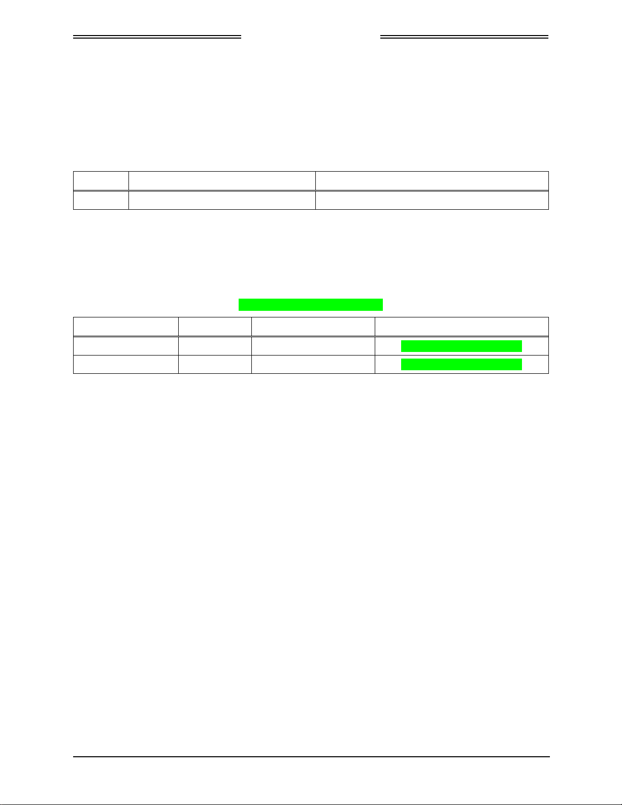
Table 1-1: NGT-2000/2500 General Description
MODEL/ P/N DESCRIPTION INTERFACES/FUNCTIONS
NGT-2000
9022500-10000
NGT-2500 *
9022500-10000
Support GPS, ADS-B IN/OUT, and
Wi-Fi.
Supports GPS, ADS-B IN/OUT,
Wi-Fi, and interfaces with traffic
and weather displays.
• Maintenance Port
• Altitude data input
• Squawk code interception/comparator (If
optional control panel is used)
• Status indicator outputs (Required only
if CP-2500 is not used)
• Coverage indicator output (Required
only if CP-2500 is not used)
• Data Configuration Module
• RS-232 output to which an external Wi-
Fi adapter can be connected
• GPS Antenna
• UAT – L-Band Antenna
• ARINC 429 output to drive a Traffic
Display terminal. (STIF or DTIF)
• RS-422 output to drive standard RS-422
displays
* Note: The NGT-2500 configuration requires a product key that is set up during installation. See paragraph 1.3.1.
0040-17011-01 General Information Page 1-1
Revision A Prel-2014

NGT-2000/2500
DRAFT 3-2
Installation Manual
1.2 FUNCTIONAL DESCRIPTION
The Multilink Surveillance System (MSS) is a family of products that provide varying levels of
functionality over a range of General Aviation (GA) aircraft (based on aircraft performance and owner
preference). The levels of functionality that can be provided across the products are as follows:
• Automatic Dependant Surveillance – Broadcast (ADS-B) Out transmitted over 978 MHz Universal
Access Transceiver (UAT) link.
• Enhanced Visual Acquisition (EVAcq) using traffic information from ADS-B In received via a UAT
link.
• Flight Information Service – Broadcast (FIS-B) using received data via UAT link.
• Interfaces with RS-232 compatible transponders for the input of the Mode A squawk Code and mode
of operation from the aircraft’s existing Air Traffic Control Radar Beacon System (ATCRBS)
transponder or through a dedicated MODE A control panel interface.
The NGT-2000/25000 has an internal GPS receiver that provides own aircraft information (position,
velocity, track (or ground track), etc.) for ADS-B Out messages and traffic display.
This GPS is not intended as a position source to a navigation management unit that outputs deviation
commands keyed to a desired flight path.
When permitted the transmission of own ship identification can be inhibited using the Anonymous Mode
function provided by the CP-2500 control panel. This may only be accomplished when VFR Mode is active.
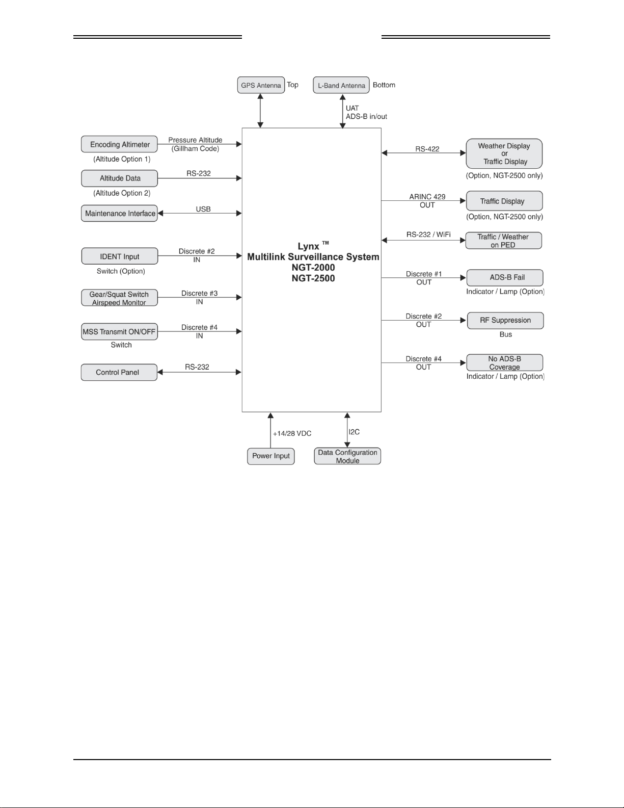
See Figure 1-1 for an overview of the unit’s system interface. The following paragraphs provide an
overview of each of these functions.
1.2.1 Enhanced Visual Acquisition Functional Overview
The Enhanced Visual Acquisition (EVAcq) function provides flight crews with a display of nearby traffic
relative to own aircraft (Cockpit Display of Traffic Information – Traffic Display) to assist with visually
acquiring traffic out the window and provide traffic situational awareness beyond visual range. Each
displayed traffic symbol conveys aircraft position, vertical trend and altitude information. Traffic on the
display (i.e. CDTI displays or some PED applications) can be selected by the flight crew to obtain
additional traffic information such as flight identification and ground speed.
The EVAcq function can display traffic on either an integrated traffic display (STIF or DTIF) or an
external traffic display (i.e. PED).
Data received via a UAT link (Ground stations- when in a coverage area) is the ADS-B, ADS-R
Rebroadcast, and TIS-B Traffic Information Service – Broadcast (traffic information used by EVAcq).
ADS-B (UAT) traffic can be received directly from another UAT equipped aircraft. TIS-B traffic and
ADS-R traffic can only be received when in the coverage area of an ADS-B ground station.
1.2.2 GPS Functional Overview
The GPS function utilizes signals from Global Positioning System (GPS) satellite constellation and
Satellite-Based Augmentation Systems (SBAS) such as the USA Wide Area Augmentation System
(WAAS), European EGNOS, Indian GAGAN and the Japanese MSAS. Currently it supports WAAS and
WAAS compatible SBAS systems.
The GPS signals are down converted to a low Intermediate Frequency, which is then processed by a micro
controller. This internal GPS function provides position, velocity, time and integrity (NIC, NAC etc)
information to the ADS-B functions and is ADS-B rule compliant with the position resource requirements
of AC20-165A.
Page 1-2 General Information 0040-17011-01
Prel-2014 Revision A
NGT-2000/2500
DRAFT 3-2
Installation Manual
Figure 1-1: System Interface Overview
1.2.3 FIS-B Functional Overview
The Flight Information Services - Broadcast (FIS-B) function provides pilots with a cockpit display of
certain aviation weather and aeronautical information for awareness of own aircraft location with respect
to reported weather, including hazardous meteorological conditions
NOTAMS/ METARS, etc) and NAS status (TFRs) indicators.
FIS-B is advisory information only and is intended to enhance pilot decision-making during strategic
flight planning. FIS-B augments traditional sources of this information such as ATC and Flight Service
Station (FSS). FIS-B information is provided over the ADS-B Services network on the 978 MHz UAT
link when in ground station coverage.
(RADAR/AIRMETS/SIGMETS/
0040-17011-01 General Information Page 1-3
Revision A Prel-2014

NGT-2000/2500
DRAFT 3-2
Installation Manual
1.2.4 ADS-B Out Functional Overview
The ADS-B Out function supports the transmission of Automatic Dependant Surveillance – Broadcast
(ADS-B) Out on a 978 MHz UAT link. The ADS-B Out data contains information about own aircraft
such as aircraft position, velocity, direction, etc. The ADS-B function receives aircraft data to output from
an internal GPS receiver.
Pressure altitude is received from existing altitude source, and control functions such as squawk codes,
Ident, and operational mode (e.g. Mode "A", Mode "C", etc.) is obtained from an approved control panel.
1.2.5 Multiple Source Inputs Operation
The NGT-2000/2500 has multiple Altitude source connections available. There is an option, through the
configuration module, of connecting RS-232 serial altitude source or Grey code altitude source, however
only one source can be connected at a time. The altitude source must be the same source used for the
mode "C" transponder if so equipped.
1.2.6 Discrete Inputs and Outputs
The MSS has discrete inputs and outputs that can be used in place of some functions that are not available
to equipment that is compatible with the MSS. See Figure 1-1.
• The Squat/Airspeed Monitor switch signals the On Ground status to the MSS via a squat switch, gear
switch, or external airspeed sensor input.
• The IDENT command activates SPI and transmits an ident pulse. An ident pulse highlights the
aircraft’s symbol on the ATC’s radar screen and is identified on the control panel when active.
• The MSS Transmit ON/OFF function is used to stop ADS-B out transmission. Setting this discrete
OFF turns the ADS-B Failure lamp ON.
• ADS-B Failure Lamp indicates that the MSS is unable to transmit due to the following:
1. If the indicator lamp is flashing at a slow rate, then the aircraft position information is invalid or
has failed. GPS may be acquiring signal in which case when it does the lamp will stop flashing.
Flashing will last only 2 minutes before the lamp stays ON.
2. If the indicator lamp is flashing at a fast rate then a Code mismatch (squawk code) has been
detected. The squawk code must be re-entered correctly (matching the transponder) using the
control panel.
3. If the lamp is ON, then the ADS-B has failed or the MSS Transmit ON/OFF switch is set OFF.
• No ADS-B Coverage lamp is used to indicate that the unit is not receiving an ADS-B ground station
signal.
Page 1-4 General Information 0040-17011-01
Prel-2014 Revision A

NGT-2000/2500
DRAFT 3-2
Installation Manual
1.2.7 Transponder Interface
• If the aircraft is equipped with a compatible transponder that has an RS-232 control panel output
(e.g. GTX-327), then the NGT-2000/2500 can receive mode control and the squawk code directly
from that transponder.
• If the aircraft is equipped with a non-compatible transponder, then the aircraft needs a CP-2500
Control Panel installed. With the CP-2500 the NGT-2000/2500 can wirelessly intercept the Mode A
squawk Code from the aircraft’s existing ATCRBS transponder and conduct a cross check between
the transponder broadcast value and the setting of the NGT-2000/2500 Mode A control panel setting
to ensure the consistency in selected Mode A squawk code selections.
If the code entered from the control panel does not match the Mode A response from the
transponder, then a Mode A mismatch failure message is set in the control panel and the aircraft call
sign is used in the UAT Message transmissions. Pilot action is required to assure that the codes set
into the transponder and the CP-2500 always match.
If a CP-2500 is not installed, then the ADS-B Failure indicator lamp will flash ON/OFF at a fast rate
indicating a Mode A mismatch failure. Pilot action is required to correct the condition.
• If the aircraft is not equipped with transponder, then the control panel may be configured to provide
squawk code data and mode control (i.e. standby, on, ALT modes).
1.3 EQUIPMENT DESCRIPTIONS
The NGT-2000 and NGT-2500 are equipped with a main sub-D connector (J2) and RF connectors (UAT
and GPS). A USB port (J1) is available to establish communication between the NGT-2000 and a
maintenance computer for installation and maintenance activities. Both units provide ADS-B In, ADS-B
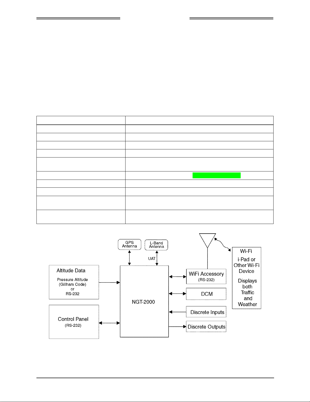
Out, ADS-R, TIS-B Traffic, FIS-B weather, NOTAMS, and TFRs functionality. Figure 1-2 shows the
NGT-2000 system interface. Figure 1-3 shows the NGT-2500 system interface.
• The NGT-2000 and NGT-2500 both provide an RS-232 output that can be used to display UAT
ADS-B traffic as well as FIS-B weather information when an external WiFi accessory is connected
to transmit the received weather data to a commercial PED (i.e. Personal Electronic Device).
• The NGT-2500 outputs ARINC 429 to interface with an onboard cockpit display of traffic
information display (STIF or DTIF) for the display of own ship (DTIF only) and traffic information.
• The NGT-2500 can interface with a RS-422 data bus output that may be interfaced to a display to
provide weather or traffic information.
The UAT ADS-B In function supports the reception of ADS-B on a 978 MHz UAT link. The ADS-B In
data contains information about proximate aircraft such as aircraft position, velocity, direction, etc. and
also receives FIS-B data and ADS-R and TIS-B data from ground stations.
The ADS-B Out function is used to broadcast (without interrogation) periodic information about the
aircraft that includes aircraft identification, position, altitude, velocity and other aircraft status
information.
0040-17011-01 General Information Page 1-5
Revision A Prel-2014
NGT-2000/2500
DRAFT 3-2
Installation Manual
The FIS-B function provides pilots and flight crews with a cockpit display of certain aviation weather and
aeronautical information for awareness of own aircraft location with respect to reported weather,
including hazardous meteorological conditions and NAS status indicators. FIS-B is advisory information
only and is intended to enhance pilot decision-making during strategic flight planning. FIS-B augments
traditional sources of this information such as ATC, Flight Service Station (FSS), and Aircraft
Operational Communications Center. FIS-B information is provided over the ADS-B Services network on
the 978 MHz UAT link.
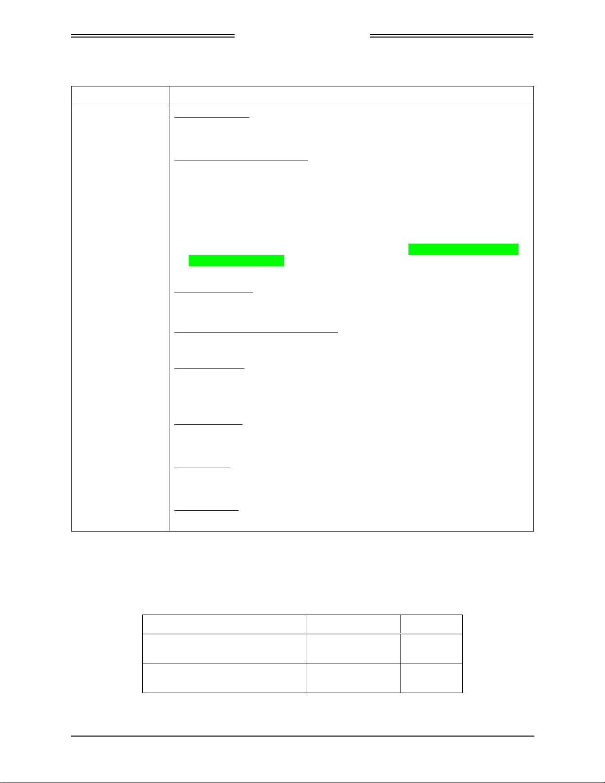
Table 1-2 describes the available built-in interfaces. Refer to Appendix A for detailed information on the
interface options. The traffic and weather display interfaces are only available to the NGT-2500 system
and requires a system product key to activate. See paragraph 1.3.1.
Table 1-2: MSS Built-in Interfaces
Interface (no.) Functionality
ARINC 429 Output (1) (NGT-2500 only) Transmit to a display(STIF or DTIF)
RS-232 Input / Output (2) Control Panel port and Wi-Fi accessory port
RS-232 Input (1) Altitude Encoder port
RS-422 Input / Output (1) (NGT-2500 only) Communicate with an external display port
Discrete Inputs (14)
Discrete Output (4) Transmit ADS-B Failure and No ADS-B Coverage.
RF Suppression Input / Output (1) Provides on aircraft suppression of the L-band equipment
I2C Port (1) Configuration Module
GPS Antenna Port
L-Band Antenna Port
Receive Gillham Altitude Encoder, IDENT Command, In Air /
On Ground status, MSS Transmit ON/OFF
Connect to a top mount antenna providing GPS data to support
ADS-B functionality
Connects to the bottom mount antenna. Provides UAT 978
MHz input and output to support ADS-B functionality.
Figure 1-2: NGT-2000 Block Diagram
Page 1-6 General Information 0040-17011-01
Prel-2014 Revision A

NGT-2000/2500
DRAFT 3-2
Installation Manual
Figure 1-3: NGT-2500 Block Diagram
1.3.1 System Product Key
A product key is required if installing the NGT-2500 option. The product Key is a 10 digit code that is
used during installation and requires the NGT MAT to configure the unit. The product key is typically
shipped with the unit. If the product key is not included, contact L-3 Avionics Systems Customer Service
to obtain the code. Be sure to have the Mode-S ID (e.g. ICAO) available for the service representative.
1.3.2 Data Configuration Module
The NGT-2000/2500 interfaces to a Data Configuration Module (DCM), part number 9230-17003-01 for
the storage of configuration data. The DCM is permanently installed in the wire harness and interfaces to
NGT-2000/2500 via a 4 wire interface from the DCM.
The configuration settings are stored in the unit’s non-volatile memory and are entered via commands
sent over the maintenance interface to configure such items as:
• I/O port allocation (e.g. which external equipment is tied to RS-232 and ARINC 429 Tx lines, etc.).
• Aircraft Configuration Data (specific aircraft ID information, 24 bit unique ICAO address, make,
model, registration, etc).
• Mode A Control Panel type (RS-422).
• Optional equipment installation settings.
If the configuration data in the unit is not self-consistent (contains contradictory settings), the DCM is faulty
or the DCM has corrupted data, the unit will annunciate a failed state and not transmit ADS-B position
reports. A change in configuration data or replacement DCM will be needed to restore the unit to operation.
0040-17011-01 General Information Page 1-7
Revision A Prel-2014

DRAFT 3-2
1.4 SPECIFICATIONS
Table 1-3: Specifications for the NGT-2000 and NGT-2500
NGT-2000/2500
Installation Manual
PART NUMBER:
CERTIFICATION:
ADVISORY CIRCULARS:
RTCA COMPLIANCE:
SIZE:
WEIGHT:
CHASSIS GROUND:
POWER REQUIREMENTS:
9022500-10000
TSO-C145c, C154c, C157a, C195a.
For more information on TSO information, refer to paragraph 1.5.
Listed are current certifications at time of publication, contact Field
Service Engineering for latest certification information.
AC 20-165A (ADS-B Out), AC-20-172A (ADS-B In), AC20-138D
(GPS), AC20-149A (FIS-B)
Environmental Category: DO-160G (See Environmental
Qualification Form in Appendix B.)
Software Category: DO-178B, Level C
Hardware Category: DO-254 Level C
Other: DO-229D, DO-282B, DO-317A, DO-267A, FAR 91.227
Height 2.8 inch [71.6 mm]
Width 4.5 inch [114 mm]
Length 5.7 inch [145 mm]
1.0 lb nominal
Bonding impedance between aircraft ground and the MSS Chassis
must be less than 2.5 milliohms.
Main Power 14 Vdc/28 Vdc, 8.9 watts nominal, 10.1 watts MAX
ELECTRICAL CONNECTORS:
OPERATING TEMPERATURE:
STORAGE TEMPERATURE:
MAXIMUM ALTITUDE:
SCHEDULED MAINTENANCE:
SERVICE LIFE:
REPAIRABILITY:
• J2 [62 pin] Mates with P/N M24308/2-14 (TE connectivity) or
L-3AS P/N 9001640-002 with backshell P/N 3050-17000-01
(See installation kit P/N 9060-17250-01)
• J1 is a Mini-b USB connection (5 pin) Maintenance Port
• RF Connector (2): 5W5 Coax D-Sub
-45° to +70°C (-49° to 158°F)
-55° to +85°C (-67° to +185°F)
Operating:18,000ft (5486 meters)
Tested: 25,000 ft (7620 meters)
NOTE: the unit is tested at 25,000 ft, however the UAT device is
restricted to 18,000 ft for transmit.
None
The unit has unlimited service life.
Repairs performed at the FAA certificated Repair Station co-located
at the OEM (equipment) facility.
Page 1-8 General Information 0040-17011-01
Prel-2014 Revision A

NGT-2000/2500
DRAFT 3-2
Installation Manual
Table 1-4: Specifications for Configuration Module
PART NUMBER:
CERTIFICATION:
RTCA COMPLIANCE:
WEIGHT:
SIZE:
POWER REQUIREMENTS:
INTERFACE (S):
OPERATING TEMPERATURE:
STORAGE TEMPERATURE:
9230-17003-01
USA (FAA):
TSO-C145c, C154c, C157a, C195a. Configuration module installed
with NGT-2000/2500
For more information on TSO information, refer to paragraph 1.5.
Listed are current authorizations at time of publication, contact Field
Service Engineering for latest certification information
Environmental Category: DO-160F
See Environmental Qualification Form in Appendix B.
Negligible
Length: 6 inches (includes wires)
3.3 Vdc (regulated via J1 connector)
I2C serial interface
-40° to +70°C (-40° to +158°F)
-55° to +85°C (-67° to +185°F)
MAXIMUM ALTITUDE:
SCHEDULED
MAINTENENACE:
SERVICE LIFE:
REPAIRABILITY:
55,000 ft (installation environment)
None.
Unlimited.
Replacement only.
0040-17011-01 General Information Page 1-9
Revision A Prel-2014

NGT-2000/2500
DRAFT 3-2
Installation Manual
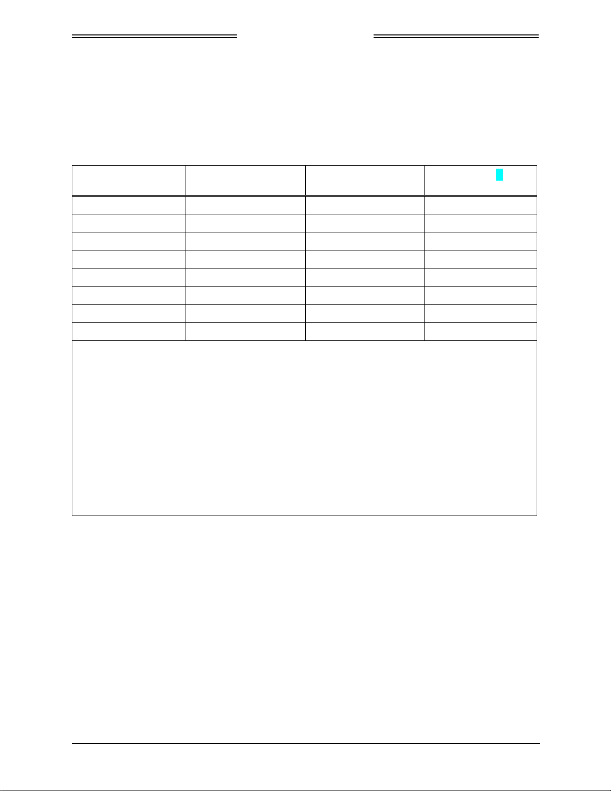
1.5 TSO INFORMATION
TSO NO. FUNCTION TSO TITLE CONFIGURATION
TSO-C157a FIS-B Display
(RS-422)
TSO-C145c GPS SBAS
Output
TSO-C195a ASSAP and
ARINC 735
based traffic
display Support
TSO-C154c UAT-IN Universal Access Transceiver (UAT)
TSO-C154c UAT-OUT Universal Access Transceiver (UAT)
Aircraft Flight Information ServicesBroadcast (FIS-B) Data Link Systems and
Equipment
Airborne Navigation Sensors Using The
Global Positioning System Augmented By
The Satellite Based Augmentation System
Avionics Supporting Automatic Dependent
Surveillance – Broadcast (ADS-B) Aircraft
Surveillance Applications (ASA)
Automatic Dependent SurveillanceBroadcast (ADS-B) Equipment Operating
on Frequency of 978 MHz
Automatic Dependent SurveillanceBroadcast (ADS-B) Equipment Operating
on Frequency of 978 MHz
1.5.1 TSO Markings
NGT-2500
NGT-2000/2500
NGT-2500
NGT-2000/2500
NGT-2000/2500
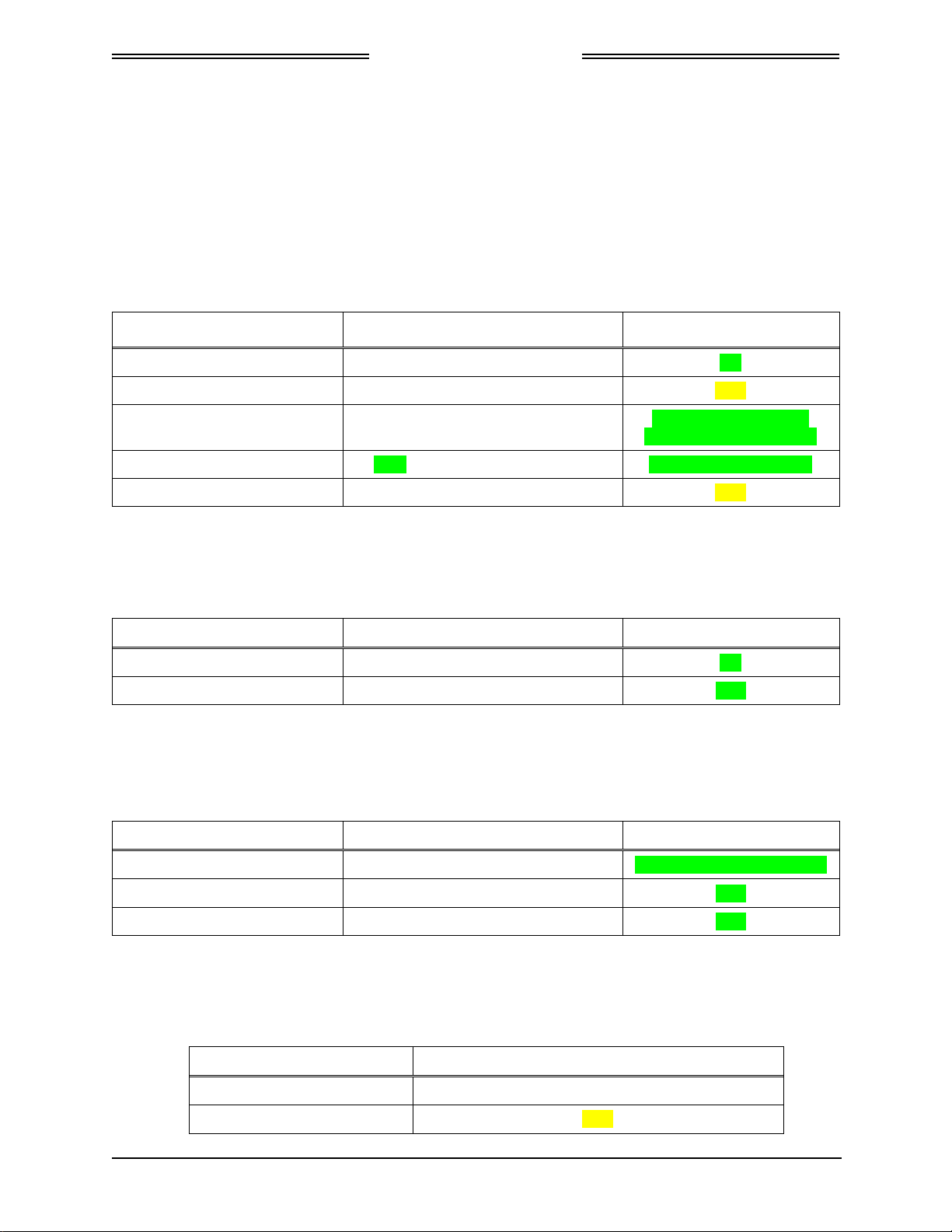
The following information summarizes the TSO application for the NGT-2000, NGT-2500, and the
installed configuration module.
TSO NO. TSO MARKING TSO TITLE
TSO-C145c TSO-C145c Class Beta 1
TSO-C154c TSO-C154c Class A1S
TSO-C157a TSO-C157a Class 2
Incomplete
TSO-C195a TSO-C195a Class C1
Airborne Navigation Sensors Using The Global
Positioning System Augmented By The Satellite Based
Augmentation System
Universal Access Transceiver (UAT) Automatic
Dependent Surveillance-Broadcast (ADS-B) Equipment
Operating on Frequency of 978 MHz
Aircraft Flight Information Services-Broadcast (FIS-B)
Data Link Systems and Equipment
Avionics Supporting Automatic Dependent Surveillance
– Broadcast (ADS-B) Aircraft Surveillance Applications
(ASA)
Page 1-10 General Information 0040-17011-01
Prel-2014 Revision A

NGT-2000/2500
DRAFT 3-2
Installation Manual
1.5.2 TSO Deviations from Minimum Performance Standards
The following information lists the TSOs for the unit that requires a deviation to Minimum Performance
Standards (MPS) that are called out in the TSO and provides the justification for the deviation.
TSO NO. DEVIATION
TSOC-145c TSO requires use of DO-160E for environmental qualification testing; DO-160G was
used instead.
TSOC-145c
TSO-C154c
TSO-C157a
TSOC-145c
TSO-C154c
TSO-C157a
TSO-C154c The RF radiated emissions to exceed the Category L requirement for the RF radiated
Per the guidance in FAA Order 8150.1c, the appliances are marked with the primary
TSO along with a reference to the Installation Manual for the other TSO information
(other applicable TSOAs, deviations, etc.).
The NGT-2500 utilizes a Maintenance Computer (i.e., a “special tool”) as its primary
support tool required for installation and debug effort. All installations will require that
the Maintenance Computer be used to verify the software part number that is stored
electronically in the unit thereby ensuring the part has been installed in compliance to
the type design data. All software updates will also require that the Maintenance
Computer be used to verify the software part number that is stored electronically in the
unit thereby ensuring the part is in compliance to the type design data.
emission limit in the following frequency bands:
• 1956 MHz ± 2.25MHz (2nd Transmitter harmonic) Exceeds Cat L by as much as 30dB
• 2934MHz ± 1MHz (3rd Transmitter harmonic) Exceeds Cat L by as much as 14dB
• 3912MHz ± 1MHz (4th Transmitter harmonic) Exceeds Cat L by as much as 15dB
• 4890Mhz ± 1MHz (5th Transmitter harmonic) Exceeds Cat L by as much as 8dB
• 5868Mhz ± 1MHz (6th Transmitter harmonic) Exceeds Cat L by as much as 3dB
Meets DO-282B spectrum reply bounds. There is limited average radiated power in the
deviation magnitudes due to the very low duty cycle. There are no defined aeronautical
safety related operations utilizing these frequencies. For this deviation, the NGT-2500
Installation Manual will direct the installer to specifically verify non-interference with
other avionic systems for these frequencies (See Installation Checkout section).
1.5.3 Non-TSO Functions
The NGT-2000 and NGT-2500 do not have any Non-TSO functions.
0040-17011-01 General Information Page 1-11
Revision A Prel-2014
NGT-2000/2500
DRAFT 3-2
Installation Manual
1.6 MODIFICATIONS
Modifications (MODS) to the NGT-2000/2500 are identified below and are identified by an entry on the
I.D tag on individual units.
Table 1-5: Hardware Modifications
MOD # EFFECTIVITY / COMPLIANCE DESCRIPTION
None
1.7 SOFTWARE REVISIONS
Software revisions and database versions are viewed using the MPC via the Maintenance Application
Tool. A list of current software revisions is identified below.
Table 1-6: Software Revisions
DESCRIPTION REVISION PART NUMBER COMPATIBLE NGT MAT
Composite Software 1.0 9021105-001 8010-17002-0001, Rev 1.0
Boot Loader 1.0 9021110-001 8010-17002-0001, Rev 1.0
1.8 INTERFACES
The electrical characteristics of all input and output signals are detailed in Appendix A.
Page 1-12 General Information 0040-17011-01
Prel-2014 Revision A

NGT-2000/2500
DRAFT 3-2
Installation Manual
1.9 EQUIPMENT REQUIRED NOT SUPPLIED
Use Table 1-7 to identify equipment required for installation, calibration, and testing.
NOTE
Equivalent tools, equipment and hardware may be used.
Table 1-7: Equipment List
ITEM DESCRIPTION
Cables and Wiring: The installer supplies all system wires and cables.
Mating Connector (P1)
• Wires are #22 AWG as noted on interconnect wiring diagram in section 2.
Use M22759 or equivalent wire and use M27500 or equivalent for twisted
shielded Tefzel wire for installation.
WiFi Accessory Connector
• 9-Pin Sub-D Connector, P/N M24308/2-1 or equivalent. Use M27500 or
equivalent for twisted shielded wire for installation as noted on interconnect
wiring diagram.
Antenna Cables
• L-Band and GPS Antenna
Require M17/128-RG400 or equivalent Coaxial Cable. Attenuation must not
exceed 1.5db per cable (including the connectors). Refer to Table 1-9.
NOTE
RG type coaxial cable insertion loss can vary significantly between
manufacturers. Refer to the cable manufacturer's specification sheet for
actual attenuation (insertion loss) for the cable being used.
Circuit Breaker: Installer is responsible for determining appropriate circuit breakers needed to
protect aircraft wiring. Manufacturer recommends the following:
• 1.0 Amp circuit breaker for the installations with 28Vdc input
• 1.5 Amp circuit breaker for the installations with 14Vdc input
If installing the NGT-2000/2500 with a CP-2500 Control Panel:
• 2.5 amp breaker (connected to same breaker as NGT-2000/2500
with 14Vdc input)
• 2.0 amp breaker (connected to same breaker as NGT-2000/2500
with 28Vdc input)
Consumables: Antenna Sealant
• For pressurized aircraft, use a sealant that meets the requirements of SAE
AMS-S-8802 such as Flamemaster® CS3204 class B. For non-pressurized
aircraft, use a non-corrosive sealant that meets the physical requirements of
MIL-A-46146 such as General Electric RTV162.
Surface Preparation
• Alodine® No. 1001 required for installation of the antenna.
0040-17011-01 General Information Page 1-13
Revision A Prel-2014

NGT-2000/2500
DRAFT 3-2
Installation Manual
Table 1-7: Equipment List
ITEM DESCRIPTION
Hardware: The following items are commercially available and is the responsibility of the
installer:
• Ring Terminals (For Grounding).
• Solder Sleeves.
• Cable tie/Tie wrap.
• Ground Braid (RAY-101-20.0/AA59569R36TXXXX or equivalent).
• Coaxial connectors.
• Status indicator lamps, placards (“fail lamp”).
• Fusion tape.
• No. 6 Mounting Screws, washers and nuts (mounting hardware).
Installation Tools:
Installation Kits:
Software:
• Insertion/Extraction tool CIET-20HD.
• Crimp Tool: P/N: M22520/2-01.
• Positioner: P/N: M22520/2-08.
• Heating tool and reflector: PR-25 or PR-25D and HL1802E-ADAPT. (Tyco
Electronics) for solder sleeves.
Installation Kits for the NGT-2000/2500 are a customer option and are ordered
separately. Refer to paragraph 1.9.1 for ordering information and a parts list.
NGT Maintenance Application Tool (NGT MAT)
Tool used for diagnostics, set up configuration options, and software
downloading. The tool is only available to an Avionics Systems Authorized
Installer. Refer to paragraph 1.11 for details on how to obtain a copy or Contact
Avionics Systems Field Service for more information.
• P/N 8010-17002-0001
LynxMMS USB Driver
This driver is required for communication between the MPC and the WiFi
Accessory.
Page 1-14 General Information 0040-17011-01
Prel-2014 Revision A
DRAFT 3-2
ITEM DESCRIPTION
Test Equipment: Air Data Test Set
• Required to test altitude inputs.
Maintenance Computer (MPC)
• The MPC is a laptop computer used to operate the NGT Maintenance
Application Tool for system setup, post installation checkout and
troubleshooting.
The computer should be using Windows 7 as the operating system, 1.3 GHz
processor or greater and 512 MB or more of RAM. Other configurations may
operate normally, but they have not been tested.
The computer must also have an USB connection and the installation of the
LynxMSS USB driver.
Mini-b USB Cable
• Required if using the USB port to interface the MPC to the MSS.
DB9 F/F Standard Null Modem Cable
• Required to configure WiFi Accessory.
Flightline Tester
• IFR-6000 Ramp Test Set (with upgrade package Option #3 (1090) & #5
(UAT), Manufacturer: AEROFLEX.
GPS Generator
• GPSG-1000, Manufacturer: AEROFLEX.
Oscilloscope
• Required to verify NGT-2000/2500 suppression pulse (100 µs ±5µs, +28 V dc)
Milliohm Meter
Required to check installation bonding to aircraft structure.
1.9.1 Installation Kits
NGT-2000/2500
Installation Manual
Table 1-7: Equipment List
Ordering Installation Kits is a customer option. Refer to the following for ordering information:
Table 1-8: Installation Kit P/N 9060-17250-01
DESCRIPTION PART NUMBER QTY
Hood-Sub Shell Size 4 Alum. With
rotating JA
Connector D Sub Receptacle Hi
Density 62 Positions Crimps
3050-17000-01 1
9001640-002 1
0040-17011-01 General Information Page 1-15
Revision A Prel-2014
NGT-2000/2500
DRAFT 3-2
Installation Manual
1.9.2 Antenna Cables
Table 1-9 lists examples of the recommended antenna cable vendors and the type of cable to be used for
specific lengths of cable. Any cable meeting specifications is acceptable for the installation.
Table 1-9: Coaxial Cable Specifications
INSERTION LOSS
(DB/100FT) [1]
18.5 N/A M17/128-RG400 RG-400
11.1 N/A M17/112-RG304 RG-304
9.2 N/A M17/127-RG393 RG-393
15.2 3C142B N/A N/A
9.2 311601 N/A N/A
7.5 311501 N/A N/A
5.8 311201 N/A N/A
3.8 310801 N/A N/A
[1] RG type coaxial cable insertion loss can vary significantly between manufacturers. The insertion
loss for RG type cables shown in this column is considered 'worst case'. Refer to the cable
manufacturer's specification sheet for actual attenuation (insertion loss) for the cable being
used.
[2] Supplier information (for reference only):
Carlisle IT
5300 W. Franklin Drive
Franklin, WI 53132
Tel: 800-327-9473
414-421-5300
Fax: 414-421-5301
www.carlisle.com
[3] Supplier information: See current issue of Qualified Products List QPL-17.
CARLISLE IT TYPE [2] MIL-C-17 TYPE [3]
RG TYPE
Page 1-16 General Information 0040-17011-01
Prel-2014 Revision A

NGT-2000/2500
DRAFT 3-2
Installation Manual
1.10 EQUIPMENT INTERFACES
The equipment listed here is compatible with the NGT-2000/2500. Equipment interfaces not listed in this
section can still be approved for installation, but must meet the requirements for the NGT-2000/2500.
1.10.1 GPS Antenna
All listed GPS antennas have TNC connector.
Table 1-10: Approved GPS Antennas
MANUFACTURER PART NUMBER
Aero Antenna AT575-326
Aero Antenna AT575-493
Aero Antenna AT575-343
Aero Antenna AT575-516
Aero Antenna AT135-3
Sensor Systems S67-1575-135
Sensor Systems S67-1575-137
Sensor Systems S67-1575-145
Sensor Systems S67-1575-160
1.10.2 UAT Antenna
MANUFACTURER PART NUMBER CONNECTOR TYPE
RAMI AV-74 BNC
Comant CI-105 BNC
Comant CI-105-11 TNC
Comant CI-2580-200
Comant CI-2728-410
Comant CI 428-200
Comant CI 429-200
Comant CI 429-410
Table 1-11: Approved UAT Antennas
0040-17011-01 General Information Page 1-17
Revision A Prel-2014
NGT-2000/2500
DRAFT 3-2
Installation Manual
1.10.3 Traffic Displays
Traffic information is output to a compatible traffic display from the NGT-2000/2500 using an ARINC
735B interface format. Possible traffic output format selections include Standard TCAS Intruder File
(STIF or TIF) and Display Traffic Information File (DTIF). The NGT-2000/2500 allows installed
configuration selection of STIF, DTIF, or both formats of output data via the ARINC 429 bus to the
traffic display. Displays not listed below can still be approved for installation, but must meet the
specifications required by the NGT-2000/2500.
Table 1-12: Approved Traffic Displays
MANUFACTURER MODEL, DESCRIPTION SW LEVEL
Garmin MX-20 (Standard traffic only) 5.7
Garmin GNS430 (Standard traffic only) TBD
Garmin G-500 (Standard traffic only) GDU-620 Version 6.11
FPGA and I/O Vers – 2.1
Garmin GTN-650 (Standard traffic only) 4.0 GPS SW Vers – 5.0
Garmin GMX-200 (Standard traffic only) TBD
1.10.4 Weather Display
Table 1-13: Approved FIS-B WX Displays
MANUFACTURER MODEL, DESCRIPTION SW LEVEL
Garmin MX-20 5.7
Garmin GMX-200 2.13
1.10.5 Control Panel
Table 1-14: Approved Control Panels
MANUFACTURER MODEL, DESCRIPTION SW LEVEL
L-3 Aviation Products CP-2500 FW Rev 07 and HW Rev 00
Garmin GTX-327 2.10
Garmin GTX-330 4.40
1.10.6 WIFI Accessory
Table 1-15: Approved RS-232 to WiFi Accessories
MANUFACTURER MODEL, DESCRIPTION
Roving Network RN370M
L-3 Avionics Systems TBD
Page 1-18 General Information 0040-17011-01
Prel-2014 Revision A
 Loading...