

Page 1

ECLIPSE
Rev.001
TM
INSTALLATION MANUAL
5.8 GHz Unlicensed Band
260-668066-003
Page 2

Page 3

Eclipse Microwave Radio
Installation Manual
For FCC 5.8 GHz Unlicensed Band
August 2010
Page 4

Eclipse Installation Manual
This manual is specific to Eclipse with IRU 600 for all-indoor operation on the FCC 5.8 GHz unlicensed
band.
Compliance and Notices
260-668066-003 Rev 001 August 2010
Copyright © 2010 by Aviat Networks, Inc.
All rights reserved. No part of this publ ication may be reproduced, transmitted, transcribed, stored in a
retrieval system, or translated into any language or computer language, in any form or by any means,
electronic, magnetic, optical, chemical, manual or otherwise, without the prior written permission of
Aviat Networks Inc. To request permission, contact [email protected]
.
Warranty
Aviat Networks makes no representation or warranties with respect to the contents hereof and
specifically disclaims any implied warranties or merchantability or fitness for any particular purpose.
Further, Aviat Networks reserves the right to revise this publication and to make changes from time to
time in the content hereof without obligation of Aviat Networks to notify any person of such revision or
changes.
Safety Recommendations
The following safety recommendatio ns must be c onsidered to avoid injuries to persons and/or damage
to the equipment:
Installation and Service Personnel: Installation and service must be carried out by authorized personnel
who have the technical training and experience necessary to be aware of any hazardous operations
during installation and service, and of measures to avoid any danger to themselves, to any other
personnel, and to the equipment.
Access to the Equipment: Access to the equipment in use must be restricted to service personnel only.
Safety Norms: Recommended safety norms are detailed in the Health and Safety sections of this
manual. Local safety regulations must be used if mandatory. Safety instructions in this document
should be used in addition to the local safety regulations. In the case of conflict between safety
instructions stated in this manual and those indicated in local regulations, mandatory local norms will
prevail. Should local regulations not be mandatory, then the safety norms in Chapter 2 will prevail.
Service Personnel Skill: Service personnel must have received adequate technical training on
telecommunications and in particular on the equipment this manual refers to.
Trademarks
All trademarks are the property of their respective owners.
ii Aviat Networks
Page 5

Eclipse Installation Manual
Open Source Software
The software included in this product contains copyrighted software that is licensed under the GPL. A
copy of that license and the complete corresponding source code is included on the CD that is shipped
with the product. You may also obtain the complete corresponding source code from us for a period of
three years after our last shipment of this product, by contacting us at
[email protected].
Product Compliance Notices
Eclipse has been tested for and meets EMC Directive 2004/108/EC. The equipment was tested using
screened cable; if any other type of cable is used, it may violate compliance.
Eclipse is a Class A product. In a domestic environment this product may cause radio interference in
which case the user may be required to take adequate measures. This equipment is intended t o be used
exclusively in telecommunications centers.
WARNING
Making adjustments and/or modifications to this equipment that are not in
accordance with the provisions of this instruction manual or other
supplementary documentation may result in personal injury or damage to
the equipment, and may void the equipment warranty.
FCC Notices
1. Eclipse with IRU600, 5.8 GHz, must be professionally installed and maintained.
2. This equipment has been tested and found to comply with the limits for a Class A digital device,
pursuant to Part 15 of the FCC rules. These limits are designed to provide reasonable protection
against harmful interference when the equipment is operated in a commercial environment. This
equipment generates, uses and can radiate radio frequency energy and, if not installed and used in
accordance with the instruction manual, may cause harmful interference to radio communications.
Operation of this equipment in a residential environment is likely to cause harmful interference in
which case the user will be required to correct the interference at his own expense.
3. Eclipse with IRU600, 5.8 GHz, is compliant with FCC CFR47, Part 15.247.
4. To ensure compliance with the FCC RF exposure requirements, a minimum distance of 20 meters
must be maintained between the antenna and any persons whilst the unit is operational. This
calculation is based on the maximum conducted power and maximum antenna gain.
5. Eclipse with IRU600, 5.8 GHz, has been tested and certified for use with a parabolic antenna with
a maximum gain of 46.8 dBi.
6. The filters provided with this product allow for transmission only in the frequency range 5725 5850MHz to ensure compliance with Part 15.247.
7. According to the conducted power limit in FCC CFR 47, Part 15.247, the power for this device has
been limited to 1W (30dBm) at the antenna port.
260-668066-003 Rev 001 August 2010 iii
Page 6

International Use of 5.8GHz
This system does not employ DFS and, and as such the equipment cannot be deployed within
Europe or any country where DFS is a regulatory requirement for protection of radars.
NEBS Compliance
The Eclipse Node comprising the INU and associated IRU 600 complies with the relevant NEBS
requirements under GR-1089-CORE and GR-63-CORE. Such compliance requires installation of the
Fan Air Filter option in the INUs, and adherence to the health and safety and equipment installation
practices described herein.
WEEE Directive
In accordance with the WEEE Directive (2002/96/EC), Eclipse is marked with the following symbol:
This symbol indicates that this equipment should be collected separately for the purposes of recovery
and/or recycling. For information about collection and recycling of Aviat Networks equipment please
contact your local Aviat Networks sales office. If you purchased your product via a distributor please
contact the distributor for information regarding collection and recovery/recycling.
More information on the WEEE Directive is available at our website: www.aviatnetworks.com/
products/compliance/weee/.
(WEEE is the acronym is for Waste Electrical and Electronic Equipment)
RoHS Directive
The RoHS (Restriction of Hazardous Substances) Directive (2002/95/EC) was implemented on 1 July,
2006. Eclipse meets the requirements of this directive, as at the implementation date.
Date of Manufacture
Eclipse date of manufacture information is contr o lled by serial number. Please contact the Aviat
Networks helpdesk for information regarding serial number format and date of manufacture.
iv Aviat Networks
Page 7

Eclipse Installation Manual
Contact Information
Sales and Sales Support:
For sales information, contact the Aviat Networks headquarters, or find your regional sales office at
http://www.aviatnetworks.com/contact-us/sales/.
Corporate Headquarters
North Carolina, USA
Aviat Networks, Inc.
5200 Great American Parkway
Santa Clara, California 95054
U. S. A.
Phone: + 1 408 567 7000
Fax: + 1 408 567 7001
Toll Free for Sales Inquiries:
+ 1 888-478-9669
Customer Service:
For customer service, contact the Technical Help Desk listed below.
Americas Technical Help Desk
Aviat Networks
5200 Great American Parkway
Santa Clara, California 95054
U. S. A.
Phone:+1 210 561 7400
Toll-free in US:
+1 800 227 8332
Fax: +1 408 944 1683
[email protected]
Or you can contact your local Aviat Networks o ffice. Contact information is available on our website at:
http://www.aviatnetworks.com/services/customer-support/technical-assistance/.
260-668066-003 Rev 001 August 2010 v
Page 8

vi Aviat Networks
Page 9

Contents
Eclipse Installation Manual .................................................................................................................. i-ii
Compliance and Notices ................................................................................................................. i-ii
CHAPTER 1, ABOUT ECLIPSE
About the Eclipse Documentation....................................................................................................... 1-x
Documentation Conventions and Terminology ............................................................................. 1-x
CHAPTER 2, HEALTH AND SAFETY
General Health and Safety................................................................................................................... 2-1
Operator Health and Safety ................................................................................................................. 2-2
General Hazards................................................................................................................................... 2-3
RF Exposure ........................................................................................................................................ 2-5
Routine Inspection and Maintenance.................................................................................................. 2-6
Routine Inspections ........................................................................................................................ 2-6
Trend Analysis ................................................................................................................................ 2-6
Fault Analysis.................................................................................................................................. 2-7
Training ........................................................................................................................................... 2-7
Spares ............................................................................................................................................. 2-7
CHAPTER 3, SYSTEM OVERVIEW
Eclipse Indoor Units............................................................................................................................. 3-2
INU .................................................................................................................................................. 3-2
INUe ................................................................................................................................................ 3-3
Plug-in Cards.................................................................................................................................. 3-3
Plug-in Cards Overview ............................................................................................................ 3-4
Eclipse IRU 600 .................................................................................................................................... 3-9
Platform Layout.................................................................................................................................. 3-10
Protection Options.............................................................................................................................. 3-12
Link/Path Protection .................................................................................................................... 3-12
Interface Protection...................................................................................................................... 3-12
Network/Data Protection ............................................................................................................. 3-12
Ring and Mesh Networks........................................................................................................ 3-13
Link Aggregation 2+0 Protection ............................................................................................ 3-13
Super PDH............................................................................................................................... 3-13
Platform Protection...................................................................................................................... 3-13
Bus Protection......................................................................................................................... 3-13
Power Supply Protection ........................................................................................................ 3-14
Eclipse Licensing ............................................................................................................................... 3-14
Configuration and Management........................................................................................................ 3-15
Eclipse Antennas................................................................................................................................ 3-15
Eclipse Power Supply ........................................................................................................................ 3-16
CHAPTER 4, INTRODUCTION TO ECLIPSE INSTALLATION
Before Going On Site............................................................................................................................ 4-1
Installation Tools and Materials .................................................................................................... 4-1
Unpacking the Eclipse Equipment.................................................................................................4-2
260-668066-003 Rev 001 August 2010 vii
Page 10

CHAPTER 5, INSTALLING THE IRU 600
IRU 600 Installation Procedure ............................................................................................................5-1
Ventilation Requirement............................................................................................................5-2
Grounding........................................................................................................................................5-2
Safety Requirements for Equipment Grounding ......................................................................5-3
Waveguide Grounding................................................................................................................5-3
NEBS Compliance .....................................................................................................................5-3
Connect Waveguide(s) to Antenna Ports(s)....................................................................................5-4
Power Supply...................................................................................................................................5-4
CHAPTER 6, INSTALLING THE INU AND INUE
INU/INUe Description...........................................................................................................................6-1
INU Front Panel Layout ..................................................................................................................6-1
INU Power Supply ........................................................................................................................... 6-2
Power Consumption and INU Load Maximums .......................................................................6-3
PCC +24 Vdc Operation..............................................................................................................6-4
Power Cables.............................................................................................................................6-5
Fuses..........................................................................................................................................6-6
FAN Air Filter Option.......................................................................................................................6-6
Fan Air Filter Installation ..........................................................................................................6-6
Power Line Filter Option.................................................................................................................6-7
INU/INUe Installation Requirements...................................................................................................6-8
Plug-in Installation Requirements ....................................................................................................6-10
Installing an INU.................................................................................................................................6-13
viii
Aviat Networks
Page 11

Chapter1.About Eclipse
Welcome to the Eclipse User Manual.
This introduction describes:
•What Is Eclipse?
• What You Need To Know to Use Eclipse
• About the Eclipse Documentation
• Documentation Conventions and Terminology
What Is Eclipse?
Eclipse Installation Manual
Eclipse supports multiple point-to-point radios for PDH, SDH and/or Ethernet on a
single rack-mounted platform, to form a complete network node for star or ring
configurations on the 5.8 GHz unlicensed frequency band.
For an introduction to the Eclipse system, see the System Overview.
What You Need To Know to Use Eclipse
To install Eclipse, we recommend you have the following knowledge and skills:
• A basic understanding of the principles of microwave transmission.
• Installation and maintenance experien ce on PDH and SDH digital microwave radio
systems.
• Familiarity with Ethernet and/or SDH multiplexing where these traffic options are
to be employed on Eclipse.
Familiarity with the operation of a PC using the Windows operating system.
Follow health and safety procedures at all times! See Health and Safety
for complete details.
260-668066-003 Rev 001 August 2010 1-ix
Page 12
Chapter1. About Eclipse
About the Eclipse Documentation
This Installation documentation provides information on installing an Eclipse
Microwave Radio system comprising the INU/INUe and IRU 600 RFU.
Intended Audience
This information is for use by trained technicians or engineers. It does not provide
information or instruction on basic technical procedures. Aviat Networks recomme nds
you read the relevant sections of this manual thoroughly before beginning any
installation procedures on Eclipse.
Documentation Conventions and Terminology
Caution, Warning and Note Cues
The following cues are used to characterize particular types of associated supporting
information.
A caution item identifies important information pertaining to
actions that may cause damage to equipment, loss of data, or
corruption of files.
A warning item identifies a serious physical danger or major possible
problem.
A note item identifies additional information about a procedure or
function.
1-x Aviat Networks
Page 13

Chapter2. Health and Safety
This section includes the following health and safety information:
• General Health and Safety
• Operator Health and Safety
• General Hazards
• RF Exposure
• Routine Inspection and Maintenance
All personnel must comply with the relevant health and safety practices when working
on or around the Eclipse radio equipment.
The Eclipse system has been designed to meet relevant US and European health and
safety standards as outlined in IEC Publication 60950-1.
Eclipse is a Class A product. It is intended to be used exclusively in telecommunications
centers.
Local safety regulations must be used if mandatory. Safety instructions in this Volume
should be used in addition to the local safety regulations. In the case of conflict between
safety instructions stated herein and those indicated in local regulations, mandatory
local norms will prevail. Should not local regulations be mandatory, then safety norms
herein will prevail.
General Health and Safety
The following table describes general health and safety information about the Eclipse
radio.
Topic Information
Flammability The equipment is designed and constructed to minimize the risk of smoke
and fumes during a fire.
Hazardous
Materials
Hazardous
Voltage
Safety Signs External warning signs or other indicators on the equipment are not
Surface
Temperatures
No hazardous materials are used in the construction of the equipment.
The Eclipse system meets global product safety requirements for safety
extra-low voltage (SELV) rated equipment where the input voltage
be 48 V nominal, 60 V maximum.
required.
The external equipment surfaces do become warm during operation due to
heat dissipation. However, the temperatures reached are not considered
hazardous.
must
260-668066-003 Rev 001 August 2010 2-1
Page 14

Chapter2. Health and Safety
Operator Health and Safety
The following table describes the precautions that relate to installing or working on the
Eclipse radio.
Topic Information
Equipment
Protrusions
Laser and Fiber
Optic Cable
Hazards
Lifting Equipment Be careful when hoisting or lifting the antenna during installation or
Protection from RF
Exposure: Eclipse
The equipment has been designed to be free of unnecessary protrusions
or sharp surfaces that may catch or otherwise cause injury during
handling. However, always take care when working on or around the
equipment.
Eclipse fiber optic transmitters are IEC60825-1 / 21CFR1040-1 Class I
compliant and present no danger to personnel in normal use. However:
Do not look into active unterminated optical ports or fibers. If visual
inspection is required ensure the equipment is turned off or, if a fiber
cable, disconnect the far end.
Follow the manufacturer's instructions when using an optical test set.
Incorrect calibration or control settings could result in hazardous levels of
radiation.
Protect/cover unconnected optical fiber connectors with dust caps.
Place all optical fiber cuttings in a suitable container for safe disposal.
Bare fibers and fiber scraps can easily penetrate the skin and eyes.
maintenance. Antennas with their mounting hardware can weigh in
excess of 100 kg (220 lb) and require specialized lifting equipment and
an operator trained and certified in its use.
The Eclipse radio does not generate RF fields intense enough to cause RF
burns. However, when installing, servicing or inspecting an antenna
always comply with the Protection from RF Exposure guidelines. See
Exposure
.
RF
Safety Warnings When a practice or procedure poses implied or potential harm to the user
or to the radio equipment, a warning is included in this manual.
2-2 Aviat Networks
Page 15

Eclipse Installation Manual
General Hazards
The following table describes the general hazards that must be addressed when
planning and installing an Eclipse system.
For more information on health and safety when u sing Aviat Networks products, refer
to Aviat Networks’ Best Practices Guide.
Topic Information
Airflow Requirements Rack installations must be made so the airflow required for safe and
correct operation of Eclipse is not compromised. For the fan-cooled
Eclipse INUs and fan-cooled Eclipse IDUs, unobstructed air passage
must be maintained to each side of the chassis, which requires a
minimum of 50 mm (2 inches) of side spacing to any rack panels,
cable bundles or similar.
Where a Fan Air Filter is installed in an INU it must not be allowed
to become clogged with dust. Replace when necessary.Inspection
must be at not more than 12 monthly intervals when installed in
telecommunications equipment room controlled-air environments.
Otherwise, inspection is required at more frequent intervals.
EMC Eclipse has been tested for and meets EMC Directive
The equipment was tested using screened cable; if any other type
of cable is used, it may violate compliance.
Eclipse is a Class A product. In a domestic environment this product
may cause radio interference in which case the user may be
required to take adequate measures. This equipment is intended to
be used exclusively in telecommunications centers.
ESD ESD (electrostatic discharge) can damage electronic components.
Even if components remain functional, ESD can cause latent
damage that results in premature failure. Always wear proper ESD
grounding straps when changing or handling the plug-in cards and
avoid hand contact with the PCB back-plane and top-plane. Connect
your ESD grounding strap to the combined ESD and ground
connector on the INU rack ear. Spare plug-in cards or cards to be
returned for service must be enclosed in an anti-static bag. When
removing a card from the anti-static bag for installation in an INU,
or placing a card in a bag, do so at the INU and only when
connected to the INU via your ESD grounding strap.
Circuit Overloading When connecting the Eclipse, determine the effect this will have on
the power supply circuit protection devices, and supply wiring.
Check Eclipse power consumption specifications and the supply
capability of the power supply system. This check of capacity must
extend to the dc power supply and not just to an intermediate
connection point.
2004/108/EC.
Eclipse Indoor Unit and
DC Supply Grounding
260-668066-003 Rev 001 August 2010 2-3
The ground for Eclipse indoor unit(s) must be connected directly to
the dc supply system ground conductor, or to a bonding jumper
from a grounding terminal bar, or bus to which the dc supply
system grounding is connected.
Page 16

Chapter2. Health and Safety
Topic Information
Intrabuilding interfaces
and cabling for NEBS
compliance
Protection from RF
Exposure
Intrabuilding connections to/from Eclipse ports must only be
connected via intrabuilding or unexposed wiring or cabling.
Intrabuilding ports MUST NOT be metallically connected to
interfaces that connect to the OSP or its wiring. These interfaces are
designed for use as intrabuilding interfaces only (Type 2 or Type 4
ports as described in GR-1089-CORE, Issue 4) and require isolation
from the exposed OSP cabling. The addition of Primary Protectors
is not sufficient protection in order to connect these interfaces
metallically to OSP wiring.
Shielded and grounded cables must be used for intrabuilding
cabling to/from Eclipse ports. Cables must be grounded at both
ends.
When installing, servicing or inspecting an antenna always comply
with the following:
• Locate the antenna such that it does not infringe the RF exposure
guidelines for general public. Refer to
• Do not stand in front of or look into an antenna without first
ensuring the associated transmitter or transmitters are switched
off.
• At a multi-antenna site ask the site owner or operator for details
of other radio services active at the site and for their
requirements/recommendations for protection against
potentially harmful exposure to RF radiation.
• When it is not possible to switch transmitters off at a
multi-antenna site and there is potential for exposure to harmful
levels of RF radiation, wear a protective suit.
• Do not look into a waveguide port when the radio is active.
RF Exposure.
Fiber Optic Cables Handle optical fibers with care. Keep them in a safe and secure
location during installation.
Do not attempt to bend them beyond their minimum bend radius.
Protect/cover unconnected optical fiber connectors with dust caps.
Ground Connections There must be no switching or disconnecting devices fitted in
ground conductors.
Mains Power Supply
Routing
Maximum Ambient
Temperature
Mechanical Loading When installing an indoor unit in a rack, ensure the rack is securely
Eclipse dc power, IF, tributary, auxiliary and NMS cables are not to
be routed with any AC mains power lines. They are also to be kept
away from any power lines which cross them.
The maximum ambient temperature (Tmra) for an Eclipse indoor
unit is +45° C (113° F). To ensure correct operation and to
maximize long term component reliability, ambient temperatures
must not be exceeded. Operational specification compliance is not
guaranteed for higher ambients.
anchored. Ensure that the additional loading of an Eclipse indoor
unit or units will not cause any reduction in the mechanical stability
of the rack.
2-4 Aviat Networks
Page 17

Topic Information
Eclipse Installation Manual
Power Supply
Connection
Power Supply
Disconnect
Rack Mount
Temperature
Considerations
The Eclipse INUs have the +ve pin on their dc power supply
connector connected to chassis ground. It must be used with a
-48 Vdc power supply which has a +ve ground; the power supply
ground conductor is the +ve supply to the radio. For NEBS
compliance the battery return connection is to be treated as a
common DC return (DC-C), as defined in GR-1089-CORE.
• There must be no switching or disconnecting devices in this
ground conductor between the dc power supply and the point of
connection to an Eclipse system.
The Eclipse High Power IRU 600 supports wide-mouth +/-21 to
+/-60 Vdc operation. Both pins on its power supply connector are
isolated from chassis ground. For NEBS compliance the battery
return connection is to be treated as an isolated DC return (DC-I),
as defined in GR-1089-CORE.
The power supply for an Eclipse system must be located in the same
premises as the Eclipse system.
An appropriate power supply disconnect device should be provided
as part of the building installation.
If the Eclipse indoor unit is installed in a closed or multi-unit rack
assembly, the operating ambient temperature of the rack
environment may be greater than room ambient. The maximum
ambient temperature (Tmra) of +45° Celsius (113° F) applies to
the immediate operating environment of the Eclipse indoor unit,
which, if installed in a rack, is the ambient within the rack.
Restricted Access The Eclipse system must be installed in restricted access sites. The
indoor unit and associated power supply must be installed in
restricted areas, such as dedicated equipment rooms, closets,
cabinets, or the like. Access to the tower and antenna location must
be restricted
Note: For USA:
In restricted access areas install the Eclipse system in accordance
with articles 110-26 and 110-27 of the 2002 National Electrical
Code ANSI/NFPA 70, or to any subsequent update to this code for
the relevant articles.
RF Exposure
To ensure compliance with the FCC RF exposure requirements, a minimum distance of
20 meters must be maintained between the antenna and any persons whilst the unit is
operational. This calculation is based on the maximum conducted power and
maximum antenna gain.
260-668066-003 Rev 001 August 2010 2-5
Page 18

Chapter2. Health and Safety
• Eclipse with IRU600, 5.8 GHz, has been tested and certified for use with a parabolic
antenna with a maximum gain of 46.8 dBi. Higher gain antennas must not be used.
• The maximum transmit output power on the IRU 600 has been limited to a
maximum of 1W (30dBm) at the antenna port, to comply with the conducted power
limit in FCC CFR 47, Part 15.247.
Routine Inspection and Maintenance
This section overviews required and recommended inspection and maintenance
practices to ensure health and safety of installed equipment is maintained to highest
levels. For more information, refer to the Aviat publication: Best Practices.
Routine Inspections
All sites must be inspected annually, or more frequently if subject to abnormal
operating conditions such as particularly exposed sites, or sites subject to salt-spray or
heavy snow/ice loading over winter months.
The inspection should cover the physical installation including the antenna,
waveguide, equipment grounding, tower and building grounds, weatherproofing, and
general site integrity.
Where a Fan Air Filter is installed in an INU (for NEBS compliance) it must be
inspected annually, or more frequently if the INU is installed in an environment that is
nor controlled for dust exclusion.
Selected ground wires should be resistance checked and then compared with previous
checks to ensure there has been no significant change.
The operational performance of the radio and associated equipment should be checked
against their as-built figures.
Trend Analysis
Use available current and historical Eclipse alarm and performance data to determine
any trend that may lead to a failure - if allowed to continue.
Check for the following trends:
• Reducing receive signal levels
• Gradually increasing bit errors or an increasing errored seconds count
• Changes in transmit power
• Increasing occurrence of other weather related changes in performance
• Increasing occurrence of a particular hardware failure
Time spent in conducting such analysis is time well spent. Catching a problem before
it brings down the network is good network management.
2-6 Aviat Networks
Page 19

Fault Analysis
All faults, once cleared, should be the subject of a fault report. The data presented in
these reports should be analyzed from time to time to check for any common threads,
which may point to a particular weakness in the design, installation, or maintenance of
the network or to a specific component.
The time taken to restore service and the parts used should also be analyzed to see if
improvements are possible in the maintenance proce dures, main tena nce trainin g and
spares holdings.
Training
Properly trained and experienced planning and installation personnel are essential for
establishing and maintaining high integrity in a new network. Similarly, properly
trained network management and service personnel are essential for the continued
good health of a network.
The training needs for personnel should be reviewed from time-to-time to ensure they
maintain expertise in their area of work, and on the installed base.
Eclipse Installation Manual
Spares
Spares holdings should be reviewed on a regular basis to ensure the correct quantity
and type are held, and held at the most appropriate locations.
Analysis of spares usage will show any trend for excessive use of spares, which may
point to a weakness in the deployment or manufacture of the item.
Spares holdings should also be checked from time to time and if necessary brought up
to the current hardware and/or software revision level.
260-668066-003 Rev 001 August 2010 2-7
Page 20

Chapter2. Health and Safety
2-8 Aviat Networks
Page 21
Chapter 3. System Overview
This section overviews features and capabilities of Eclipse with IRU 600 for the 5.8
GHz unlicensed band.
Eclipse with IRU600, 5.8 GHz, is compliant with FCC CFR47, Part 15.247.
• It has been tested and certified for use with a parabolic antenna with a maximum
gain of 46.8 dBi.
• The filters used in the IRU 600 RF unit allow for transmission only in the frequency
range 5725 - 5850MHz to ensure compliance with Part 15.247.
• Transmit power output is limited to 1W (30 dBm) at the antenna port to comply with
the conducted power limit in FCC CFR 47, Part 15.247.
Operation is all-indoor, using rack-mounted indoor units, the INU and INUe, and one
or more IRU 600 RF units.
• Eclipse supports multiple radio links from a common indoor unit with throughput
capacities to 189 Mbit/s Ethernet, 100xDS1, 3xDS3, or 1xOC3.
• The IRU 600 RF unit is 1+1 optimized with two RFUs and an ACU. The RFUs can be
operated as independent links, or as a protected link.
• Path, equipment, and data protection options support comprehensive link, network
and data redundancy.
•Plug-in cards on the INU and INUe provide a wide choice of user interfaces and radio
link operation.
• The node-based concept eliminates most ancillary equipment and external cabling,
and offers smooth upgrade paths for next generation networks.
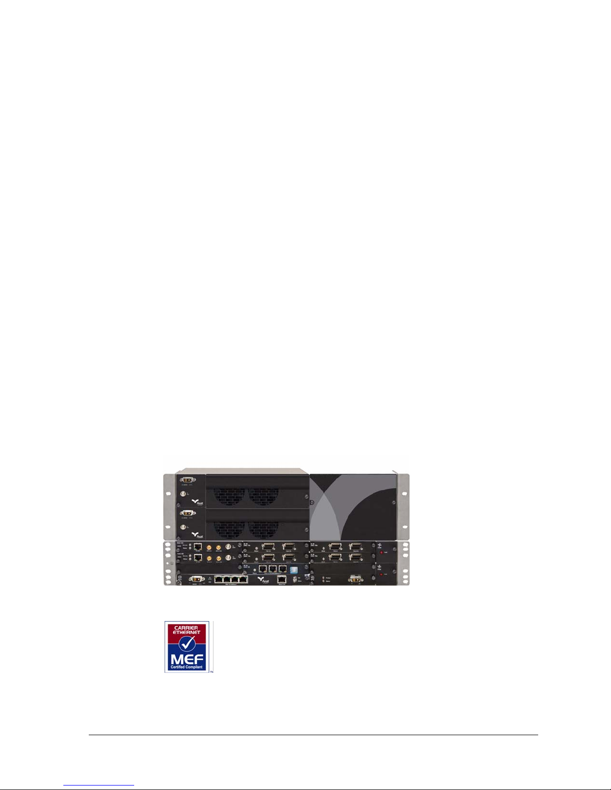
Figure 4. INUe with IRU 600
260-668066-003 Rev 001 August 2010 3-1
MEF Certified. Eclipse meets the requirements of MEF 9 and MEF 14
for carrier-class Ethernet inter-operability and performance. MEF 9
specifies the User Network Interface (UNI). MEF 14 specifies Quality of
Service (QoS).
Page 22
Chapter 3. System Overview
Refer to:
• Eclipse Indoor Units
•Eclipse IRU 600
• Platform Layout
• Protection Options
• Eclipse Licensing
• Configuration and Management
•Eclipse Antennas
• Eclipse Power Supply
Eclipse Indoor Units
INU
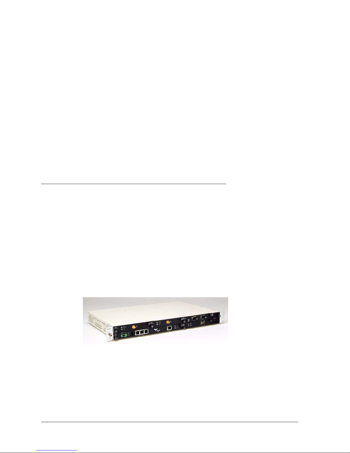
There are two indoor units, the INU, and INUe (extended INU). The INU is a 1RU
chassis, the INUe is 2RU.
Mandatory plug-ins are the NCC (Node Control Card) and FAN (Fan card). The
optional plug-ins comprise RAC (Radio Access Card), DAC (Digital Access Card), AUX
(Auxiliary), NPC (Node Protection Card), and PCC (Power Converter Card).
The INU requires one NCC and one FAN, and has provision for up to four option
plug-ins. It supports a maximum of three RFUs for three non-protected links, or one
protected/diversity link and one non-protected link. Each RFU is supported by a RAC
via a single coax cable.
Figure 3-1. INU
3-2 Aviat Networks
Page 23
INUe
Eclipse Installation Manual
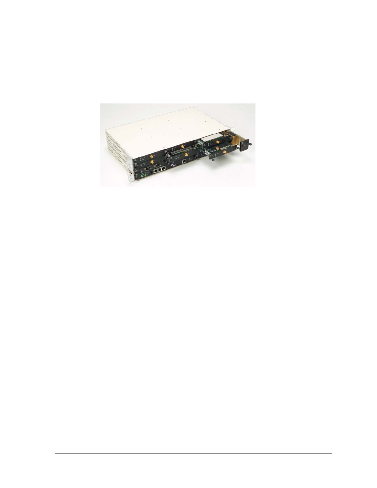
The INUe requires one NCC and one 2RU FAN. It has provision for up to ten option
cards and supports a maximum of five RFUs for five non-protected links, or two
protected/diversity links plus one non-protected link.
Figure 3-2. INUe
Plug-in Cards
Plug-in cards for the INU or INUe enable quick and easy customization on Eclipse
configurations. All cards are hot-pluggable.
• RACs support the radio modem function. In the transmit direction they take the
digital traffic from the backplane or data packet plane and convert it to an IF signal
for connection to an IRU600. The reverse occurs in the receive direction.
• One RAC with one 1+0 IRU 600 is used for a 1+0 link.
• Two RACs with one 1+1 IRU 600 are used for 1+1 or diversity links.
• RACs control TX switching and RX voting on protected / diversity links.
• XPIC (cross polarization interference cancellation) RACs support CCDP
(co-channel dual polarization) operation.
• DACs support the user interface. They take the user traffic and convert it into a
format compatible with the data backplane, where it cross-connects to a RAC or
RACs, or to other DACs.
• Different DACs support DS1, DS3, OC3, and Ethernet connections.
• Multiplexer DACs support transport of OC3 or DS3 with NxDS1 rates.
• Ethernet DACs support a L2 switch function. The GigE DAC GE supports
advanced ring/mesh, link aggregation and VLAN tagging options.
• Most DACs can be protected using a stacked (paired) configuration.
• DS1, DS3, and OC3 DACs support Ethernet-over-TDM options to enable Ethernet
transport over legacy TDM radio or leased-line links.
• AUX (Auxiliary card) supports async or sync service-channel connections, and
alarm I/O options for connection to external devices.
• NCC (Node Controller Card) provides the node management and DC voltage
conversion functions. The NCC is a mandatory card.
• It manages Eclipse operation and event collection and management.
260-668066-003 Rev 001 August 2010 3-3
Page 24

Chapter 3. System Overview
• It incorporates a router function for local and remote network management
interconnection.
• Eclipse configuration and licensing data is held in flash-memory.
• Required power supply is -48 Vdc (-40.5 to -60 Vdc).
•FAN (Fan card) provides forced-air cooling. This is a mandatory card.
• NPC (Node Protection Card) provides 1+1 protection functions for the NCC power
supply and backplane management.
• PCC (Power Conversion Card) supports operation from a a +24 Vdc power supply.
Plug-in Cards Overview
RAC 60
RAC 60 supports DPP (Data Packet Plane) as well as backplane data connections, plus
ACM (Adaptive Coding and Modulation) options.
Four dynamically switched modulation rates are available; QPSK, 16 QAM, 64 QAM,
256 QAM. Modulation switching is errorless for priority traffic.
Coding options additionally provide selection of two modulation states, one for
maximum throughput, the other for maximum gain. These apply on each of the
modulation rates of QPSK to 256 QAM to provide an effective total of eight modulation
states.
• Maximum throughput delivers maximum data throughput - at the expense of some
system gain.
• Maximum gain delivers best system gain - at the expense of some throughput.
• Up to four of the eight modulation states offered with ACM can be selected for use.
A DPP port enables direct routing of Ethernet traffic to a DAC GE.
Individual ACM modulation rates can be set as fixed rates. These are compleme nted by
fixed rates for TDM (DS1, DS3, OC3) capacities.
Channel bandwidths range from 3.5 to 30 MHz.
Air-link capacities for Ethernet, or for Ethernet + DS1, extend to 189 Mbit/s.
Backplane-connected TDM options extend to 100xDS1, 3xDS3, 1xOC3.
Payload encryption is a licensed option.
RAC 60s must be used at both ends of a link, or RAC 60 with a RAC 6X in non-CCDP
mode.
Figure 3-3. RAC 60
3-4 Aviat Networks
Page 25
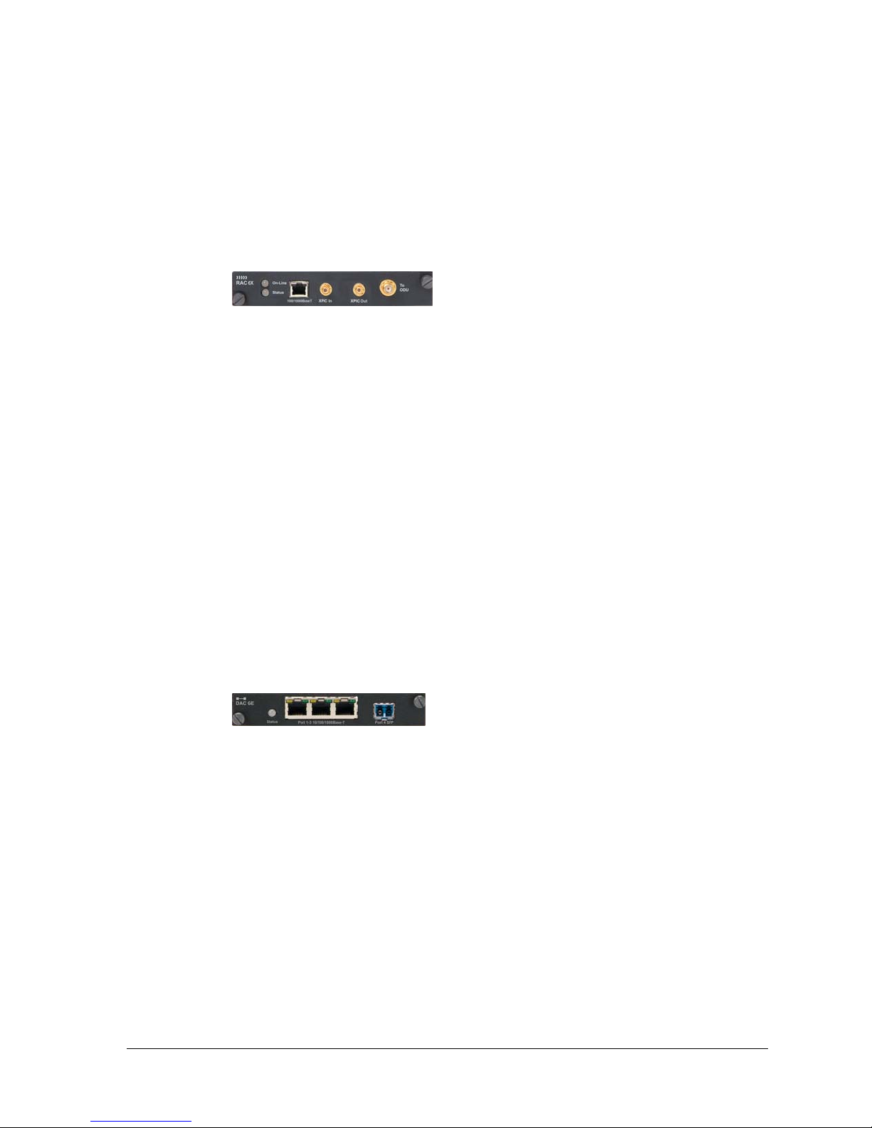
RAC 6X
DAC GE
Eclipse Installation Manual
RAC 6X adds CCDP operation to RAC 60 capabilities. Two RAC 6X cards are operated
as a CCDP pair, either in the same INU, or in separate co-located INUs to provide
double the capacity over one channel using both the horizontal and vertical
polarizations. An XPIC function between the RACs ensures cross-polarization
interference is eliminated.
Figure 3-4. RAC 6X
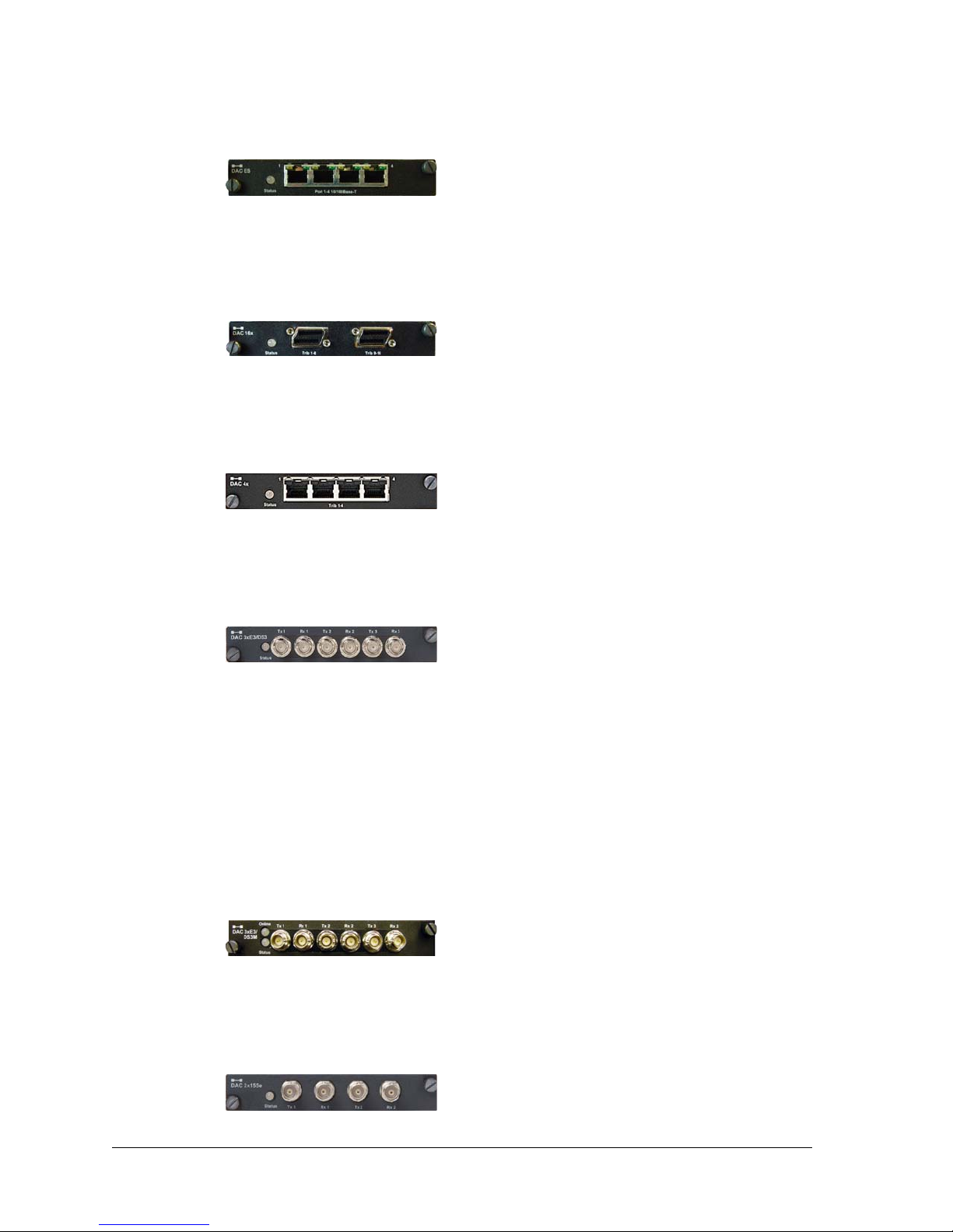
DAC GE interfaces three 10/100/1000Base-T electrical ports and one 1000Base-LX
optical port, to one or two transport channels. Features include:
• Advanced QoS settings.
• Transparent, VLAN and mixed modes of operation.
•Enhanced, fast-switched RSTP.
•Layer 1 or Layer 2 link aggregation.
• VLAN tagging.
• DPP and backplane traffic connections.
• Inter-frame gap (IFG) and preamble stripping and re-insertion.
• Frame sizes to 9600 bytes.
• Assignment to radio or fiber links.
• SFP optical port options for 1310nm single or multi-mode, or 850nm multi-mode.
• Compatibility with DAC ES.
Figure 3-5. DAC GE
For DPP traffic a DAC GE must be operated with a RAC 60 or RAC 6X.
DAC ES
DAC ES interfaces four 10/100Base-T Ethernet ports to one or two radio and/or fiber
transport channels. Features include:
• Advanced QoS settings.
• Transparent, VLAN and mixed modes of operation.
• Throughputs to 100 Mbit/s per transport channel.
• Assignment to radio or fiber links.
• Inter-frame gap (IFG) and preamble stripping and re-insertion.
• Compatibility with DAC GE.
260-668066-003 Rev 001 August 2010 3-5
Page 26
Chapter 3. System Overview
Figure 3-6. DAC ES
DAC 16X
DAC 16x supports 16xDS1 tributaries on Mini RJ-21 connectors.
Figure 3-7. DAC 16x
DAC 4X
DAC 4x supports 4xDS1 tributaries on individual RJ-45 connectors.
Figure 3-8. DAC 4X
DAC 3xDS3
DAC 3xDS3 supports 3xDS3 tributaries on paired mini-BNC connectors.
Figure 3-9. DAC 3xDS3
DAC 3xDS3M
DAC 3xDS3M supports three operational modes:
• Normal DS3 tributary operation (as for DAC 3xDS3)
• M13 multiplexer mode. One or two DS3 interfaces are multiplexed to an NxDS1
• DS3 Ethernet mode to enable up to 43 Mbit/s Ethernet over legacy TDM radio or
Tribs are supported on paired mini-BNC connectors.
Figure 3-10. DAC 3xDS3M
DAC 2x155e
backplane.
leased-line links (links must support transparent DS3).
DAC 2x155e supports two STS3 electrical tributaries on paired BNC connectors.
Figure 3-11. DAC 2x155e
3-6 Aviat Networks
Page 27
DAC 1x155o
DAC 2x155o
DAC 155oM
Eclipse Installation Manual
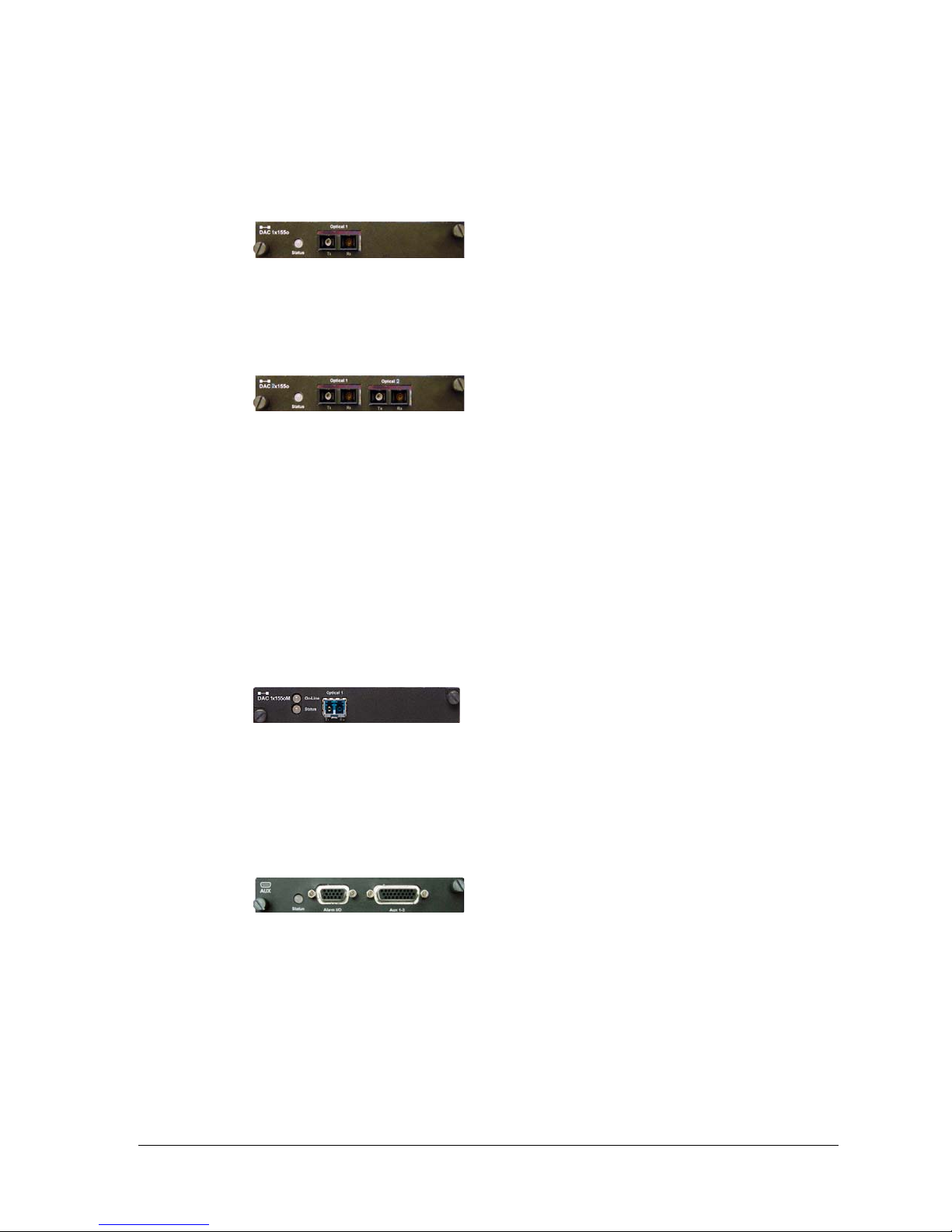
DAC 1x155o supports one OC3 single-mode optical tributary on SC connectors.
Figure 3-12. DAC 1x155o
DAC 2x155o supports two OC3 single-mode optical tributaries on SC connectors.
Figure 3-13. DAC 2x155o
DAC 155oM multiplexes an OC3 optical tributary to an NxDS1 backplane. The user
interface is provided on an SFP optical transceiver. Different SFPs support 1310nm
single or multi-mode, or 850nm multi-mode.
AUX
It functions as a terminal multiplexer; it terminates or originates the OC3 frame. It does
not support interconnection of ADMs as there is no provision to transport OC3
overheads for ADM to ADM synchronization.
In virtual tributary mode it transports up to 130 Mbit/s Ethernet over an OC3 link.
Options are provided for external/recovered, or internal clock sourcing.
Figure 3-14. DAC 155oM
AUX provides synchronous and/or asynchronous auxiliary data channels, NMS
porting, and alarm input and output functions. Data options are sync at 64 kbps or
async to 19.2 kbps.
Figure 3-15.
260-668066-003 Rev 001 August 2010 3-7
Page 28
Chapter 3. System Overview
NCC
The NCC is a mandatory plug-in for an INU/INUe. It performs key node management
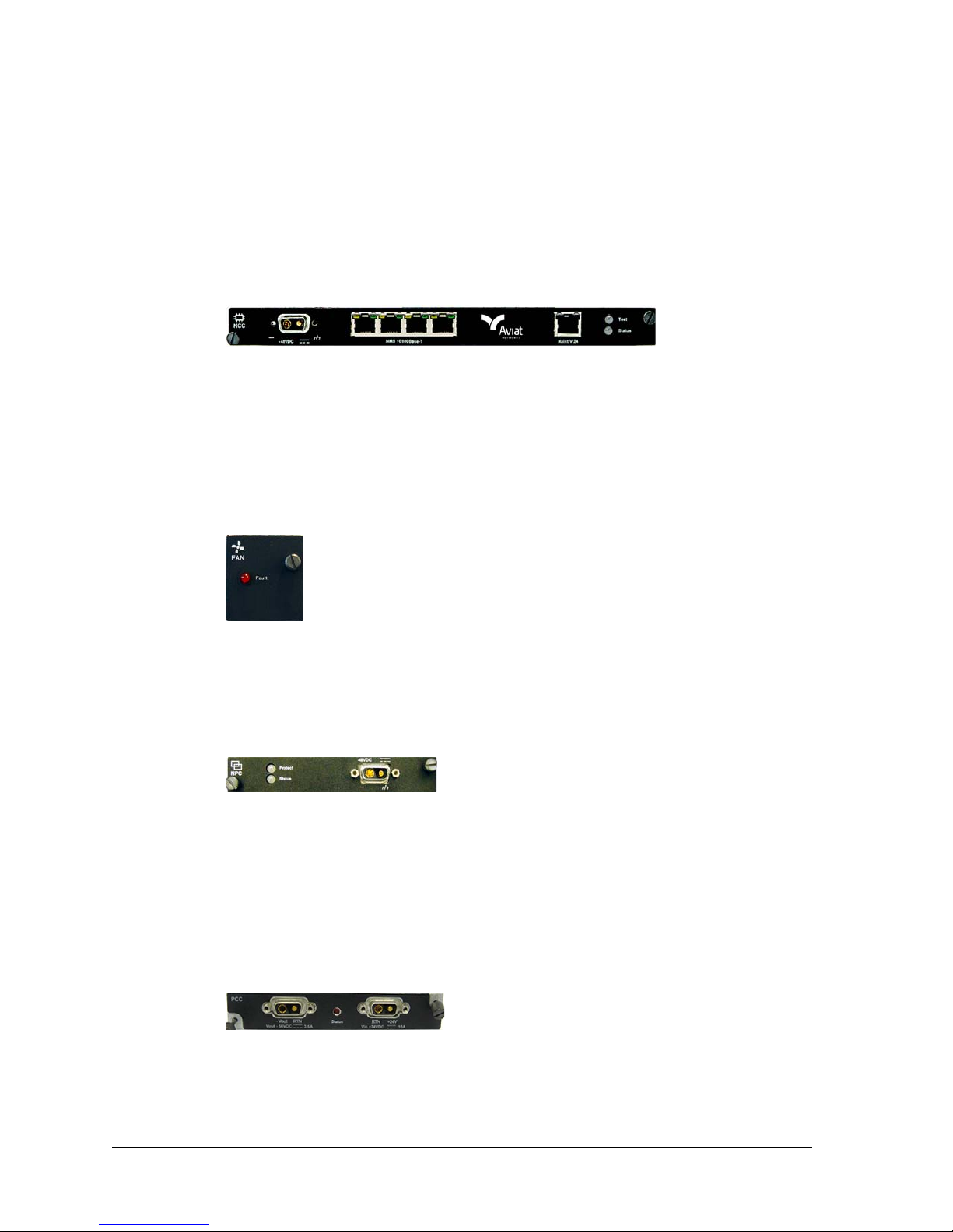
and control functions, and provides various dc rails from the -48 Vdc input. It also
incorporates a plug-in flash card, which holds Node configuration and license data.
Power input limits are -40.5 to -60 Vdc. The power connector is a D-Sub M/F 2W2. The
+ve dc return pin is connected to chassis ground.
Figure 3-16. NCC
FAN
The FAN is a mandatory plug-in. There are two variants, 2RU and 1RU. Each is fitted
with two long-life axial fans plus monitoring and control circuits.
• One 1RU FAN is fitted in an INU.
• One 2RU FAN is fitted in the INUe.
Figure 3-17. FAN ( 1RU)
NPC
PCC
NPC provides redundancy for the NCC TDM bus management and power supply
functions.
Figure 3-18. NPC
The PCC provides a voltage conversion function for locations where the power supply
is +24 Vdc. It converts + 24 (19 to 36) Vdc to -56 Vdc for connection to the INU -48Vdc
input. -56 Vdc represents the typical float voltage for a battery-backed -48 Vdc supply.
One PCC supports a maximum three IRU 600 RFUs, plus any combination of RACs
and DACs.
Figure 3-19. PCC
3-8 Aviat Networks
Page 29

Eclipse IRU 600
The IRU 600 is a 3RU rack-mounted transceiver unit for co-location with an INU/
INUe as an all-indoor installation.
IRU 600 is 1+1 optimized with provision for two RFUs (Radio Frequency Unit) and a
companion filter-based ACU (Antenna Coupler Unit).
High power and standard power RFUs are available. Both are highly energy efficient.
(50W power consumption for standard power, 98W for high power).
Transmit power output is limited (applies on the high power RFU) to a maximum of 1W
(30dBm) at the antenna port to comply with the conducted power limit in FCC CFR 47,
Part 15.247.
• Standard power RFUs are powered over the IF cable from its INU/INUe.
• High power RFUs are additionally powered using a separate DC input on the RFU
front panel.
• The power connector (D-Sub M/F 2W2) and cable is identical to that used for the
INU.
• The high power RFU provides a wide-mouth connection for +/- 21 to 60 Vdc. Both
+ve and -ve pins are isolated from ground.
• An integral DC/DC converter provides polarity protection, under/over voltage
shutdown, over-current limit, and thermal shutdown.
• NEBS compliant EMI filtering is included.
There are no serviceable fuses.
Eclipse Installation Manual
The ACU design supports paired and unpaired Tx/Rx frequency splits and incorporates
an optional expansion port to allow other radio links onto its waveguide feed for
co-path operation.
The IRU 600 also supports 1+0 repeater (back-to-back) operation. The links may be in
the same or different bands.
Protected/diversity options include:
• 1+1 hot-standby, single antenna, with equal or unequal split.
• 1+0 hot-standby-ready.
•Space diversity (dual antennas) with common or split Tx.
Figure 3-20. Low Power IRU 600
260-668066-003 Rev 001 August 2010 3-9
Page 30
Chapter 3. System Overview
Fan
Platform Layout
Eclipse supports flexible customization of traffic type, traffic capacity, and traffic
protection.
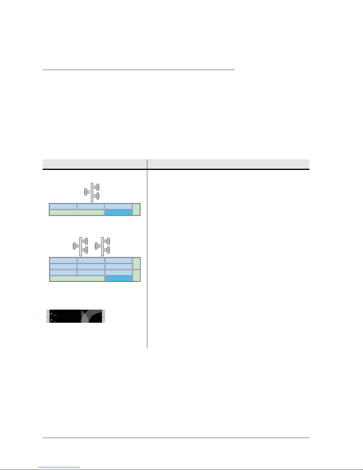
Table 3-1 lists INU and INUe platform support for:
• Non-protected and protected/diversity links
• Slot availability for option plug-ins
• Over-air data types supported
• IRU 600
Table 3-1. INU and INUe Platforms
INU • Supports 3 non-protected links or 1 protected/diversity
and 1 non-protected link
• Slots 1 to 4 support radio or traffic port options for:
Slot 1 Slot 2 Slot 3
NCC Slot 4
Fan
• Ethernet, DS1, DS3, OC3
• Auxiliary data and alarm I/O
• NPC option may only be installed in slot 4
INUe • Supports up to five 1+0 RAC 60 links or four RAC 6X
links
• Supports two 1+1 protected links (4xRACs)
• Slots 1 to 6 support radio or port options. Slots 7 to 9
Slot 1 Slot 2 Slot 3
Slot 4
Slot 7
Slot 5 Slot 6
Slot 8
NCC
Slot 9
Slot 10
Fan
support port options only. Port traffic options include:
• Ethernet, DS1, DS3, OC3
• Auxiliary data and alarm I/O
• Slot 10 is reserved for the NPC option
IRU 600 • IRU 600:
• QPSK to 256 QAM.
• Requires RAC 60 or RAC 6X. Fixed or adaptive
modulation rates.
•1+1 optimized.
• High power and standard power RFU options
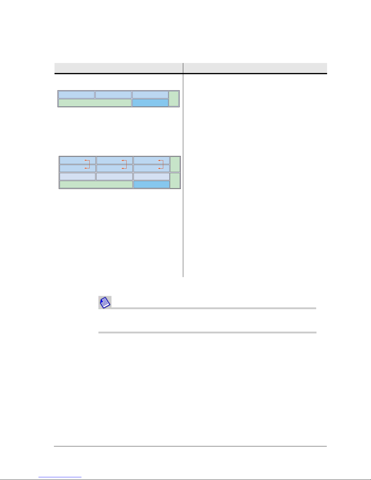
Table 3-2 lists INU and INUe slot assignment rules.
3-10 Aviat Networks
Page 31
Eclipse Installation Manual
Table 3-2. INU and INUe Slot Assignments
INU/INUe Slots
INU • Slots 1, 2, 3, 4 are universal: any RAC, DAC or
AUX plug-in
Slot 1
INUe • Slots 1, 2, 3, 4, 5, 6 are universal: any RAC,
Slot 1 Slot 2 Slot 3
Slot 4
Slot 7
NCC
NCC
Slot 2
Slot 5 Slot 6
Slot 8
Slot 3
Slot 4
Slot 9
Slot 10
Fan
• Slot 4 is NPC or universal: NPC or any RAC, DAC,
AUX
• NCC and FAN slots are dedicated
• For protected operation the RAC/RAC, RAC/DAC
155oM, or DAC/DAC pairings can be installed in
any of the universal slots
Fan
Fan
DAC or AUX plug-in
• Slots 7, 8, 9 are restricted: any DAC or AUX,
except DAC 155oM and AUX where NMS access
is required
1
• Slot 10 is restricted: NPC option only
• NCC and FAN slots are dedicated - the INUe is
supplied standard with a single 2RU FAN, though
accepts two 1RU FANs
• RAC/RAC, or RAC/DAC 155oM protected
pairings must be installed in the positions
indicated by the arrows
• For protected DACs, the protection partners can
be installed in slots 1 to 9, except for the DAC
155oM where NMS access is needed, in which
case install only in slots 1 to 6
1. Internal (backplane bus) NMS access is only provided on slots 1 to 6. Do not install DAC 155oM or AUX in
slots 7 to 9 if an NMS connection is required in their configuration.
Data is transported natively over an Eclipse wireless link, whether
Ethernet or TDM.
260-668066-003 Rev 001 August 2010 3-11
Page 32

Chapter 3. System Overview
Protection Options
Eclipse supports link, interface, network, and platform protection options:
Link/Path Protection
Hot-standby, space diversity, frequency diversity, or dual protection options are
available. RACs and their companion IRU 600 are protectable.
Rx voting is hitless/errorless; Tx switching is not hitless. The maximum restoration
time for a Tx switch is 200 ms.
A remote Tx switch is forced in the event of a silent Tx failure.
Interface Protection
DS1, DS3 and OC3 interfaces can be hot-standby protected using paired (stacked)
DACs.
The protectable DACs are DAC 16x V2, DAC 3xDS3, DAC 3xDS3M, DAC 2x155o, DAC
2x155e, DAC 155oM.
When a switch occurs, all Tx and/or Rx tributaries are switched to the protection
partner.
Two protection configurations are supported, tributary protection, and always-on:
Tributary Protection
• Y cables connect the paired DACs to customer equipment.
• In the Rx direction (from the customer) both DACs receive data, but only the online
Rx DAC sends this data to the TDM bus.
• In the Tx direction, the online Tx DAC sends data to customer equipment, the other
mutes its Tx line interface.
Tributary Always-On
• Separate cables connect each DAC to customer equipment.
• In the Rx direction (from the customer) both DACs receive data, but only the online
Rx DAC sends this data to the TDM bus.
In the transmit direction both DACs send data to customer equipment, and the
customer equipment switches between these two
Protection switching is not hitless. The maximum restoration time for a Tx or Rx trib
switch is 200 ms. Typical restoration times are between 80 ms and 120 ms.
always-on tributaries.
Network/Data Protection
•RWPR
• Data redundancy is supported on Ethernet link-aggregated links.
• Super PDH ring operation supports protection on NxDS1 ring links.
3-12 Aviat Networks
TM
supports fast-switched RSTP on Ethernet ring and mesh networks.
Page 33

Ring and Mesh Networks
RWPRTM (Resilient Wireless Packet Ring) is a fast-switched RSTP link management
protocol for layer 2 switches. RSTP, itself a fast switched evolution of the original STP,
prevents live network loops and provides path redundancy where two or more paths
exist between network nodes.
• RWPR represents a particularly effective enhanced RS TP protocol. When configured
in Eclipse ring networks, reconvergence times are as low as 50 mS.
Link Aggregation 2+0 Protection
Traffic redundancy is supported on co-channel Ethernet links using link aggregation.
If one link fails, then its traffic is recovered on the remaining link or links is shared.
While the reduced bandwidth may result in some traffic loss for low-priority traffic,
appropriate QoS settings should ensure security for all higher priority traffic. This is
often referred to as 2+0 protection.
Super PDH
Eclipse Installation Manual
Super PDHTM is exclusive to the Eclipse. It supports protected PDH ring configurations
for capacities to 84xDS1, with traffic switching at the node level.
A ring (closed loop) is formed by east/west facing RAC and RFU combinations from an
Eclipse node; each node is connected to two adjacent nodes, the east and west nodes.
Within the ring there are two traffic rings, one nominated as clockwise, the other
anti-clockwise. Under normal no-fault conditions, all traffic is passed on the clockwise
primary ring.
When a fault occurs, the secondary, anti-clockwise ring, provides the protection
capacity needed. Traffic is looped onto the sec ondary ring at one side of the break point,
and off at the other side, to bypass the break. This process is called wrapping.
One or more radio paths can be replaced by a fiber span using the DAC 155oM.
Platform Protection
Platform management functions provided by the NCC are protected using the NPC
option to protect essential Backplane Bus and power supply functions.
Bus Protection
• Protects all circuit/tributary traffic. Alarm I/O is not protected.
• Switching is not hitless for an NCC bus clock failure; restoration is within 200 ms,
during which time all traffic on the NTU is affected.
• When the bus clock has switched to NPC control, it will not automatically revert to
NCC control on restoration of the NCC. Return to NCC control requires either
withdrawal/failure of the NPC, or use of diagnostic commands.
260-668066-003 Rev 001 August 2010 3-13
Page 34

Chapter 3. System Overview
Power Supply Protection
• Protection is hitless for an NCC power supply failure. If the NCC converter or one of
its supply rails fails, the NPC will take over without interruption. And vice versa.
• With an NPC installed, the NCC can be withdrawn and replaced without further
impacting traffic.
• For 24 Vdc operation two PCCs are required for platform protection, one each for the
NCC and NPC.
Eclipse Licensing
Eclipse is subject to capacity and feature licensing.
Feature Licensing applies on selected features. Currently six features available.
• EZF-01: Layer 1 Link Aggregation (DAC GE). Traffic is between the links on a
byte-by-byte basis, based on the capacity of the links. Unlike L2, it is fully effective
for just one active session, such as between routers, or where there are only a few
concurrent sessions.
• EZF-02: Adaptive Modulation. Eclipse adaptive coding and modulation (ACM)
dynamically switches between QPSK, 16 QAM, 64 QAM, or 256 QAM. Code settings
additionally provide two sets of rates for each modulation; one for
maximum-throughput, the other for maximum-gain, to provide eight modulation
states in total.
• EZF-03: Secure Management (NMS). Applies to Eclipse NMS access over the
network, and to local access via the Portal craft tool. It also enables secure
management access to Eclipse over an unsecured network, and protects Eclipse
configurations from accidental or intentional modification by unauthorized
personnel.
• EZF-04: Payload Encryption. Encrypts all traffic and management data over the
wireless link to prevent eavesdropping.
• EZF-05: Ethernet over TDM (DS3, DS1). Enables mapping of Ethernet data to
DS3, or DS1 PDH interfaces using the DAC 3xDS3M or DAC 16xV2. Supports
transport of Ethernet data over existing DS3 or NxDS1 radio or leased-line circuits.
• EZF-06: RADIUS Client. Enables connection validation to a radius server for
centralized account management.
3-14 Aviat Networks
Page 35

Eclipse Installation Manual
Configuration and Management
Eclipse is a software-driven product; there are no manual controls. Configuration and
management is achieved via Portal and ProVision.
• Portal is a PC based configuration and diagnostics tool for Eclipse.
• ProVision is the Eclipse network element manager. ProVision also supports other
Aviat products, including legacy products.
Portal is supported in the Eclipse system software, such that once installed on a PC, it
automatically downloads support from the radio as needed to ensure Portal always
matches the version of system software supplied, or subsequently downloaded in any
radio upgrade.
Portal has the look and feel of a Windows environment with screen-based views and
prompts for all configuration and diagnostic attributes.
A Portal PC connects to an INU/INUe/IDU using Ethernet or V.24 options.
For more information, refer to the Eclipse Configuration Guide.
ProVision is the network element manager for all Aviat radios (current and legacy).
ProVision also supports partner products, including multiplexors, switches, routers,
and power systems.
ProVision is installed on a Windows or Solaris server, typically at a network operating
center, and communicates with network elements using standard LAN/WAN IP
addressing and routing; each radio has its own unique IP address.
For more information, refer to the Aviat ProVision User Guide.
Eclipse Antennas
Antennas for the 5.8 GHz unlicensed band must be FCC approved.
Antenna gain must not exceed 46.8 dBi.
For information on antenna types and availability, contact Aviat Networks or your
supplier.
Antenna mounts are designed for use on industry-standard 115 mm OD (4.5 inch)
pipe-mounts.
For information on installing and aligning antennas, refer to the data supplied with the
antennas.
260-668066-003 Rev 001 August 2010 3-15
Page 36

Chapter 3. System Overview
Eclipse Power Supply
Eclipse is designed to operate from a -48 Vdc power supply (+ve earth) but will operate
to specification over a voltage range of -40.5 to -60 Vdc.
A plug-in PCC option provides a voltage conversion function for locations where the
power supply is +24 Vdc. It converts + 24 (19 to 36) Vdc to -56 Vdc for connection to
the INU -48Vdc input. -56 Vdc represents the typical float voltage for a battery-backed
-48 Vdc supply.
One PCC supports a maximum three IRU 600 RFUs, plus any combination of RACs
and DACs.
The dc power supply must be UL or IEC compliant for SELV (Safety Extra Low Voltage)
output (60 Vdc maximum limited).
3-16 Aviat Networks
Page 37
Chapter 4. Introduction to
Eclipse Installation
This section introduces Eclipse installation procedures, from unpacking and checking
the equipment to completion of the physical installation.
Eclipse has been tested for and meets EMC Directive 2004/108/EC. The
equipment was tested using screened cable; if any other type of cable i s
used, it may violate compliance.
Eclipse is a Class A product. In a domestic environment it may
cause radio interference: be prepared to resolve this. Eclipse
equipment is intended to be used exclusively in
telecommunications centers.
You must comply with the relevant health and safety practices when
working on or around Eclipse radio equipment. R efer to Health and Safety.
Before Going On Site
Installation Tools and Materials
Ensure you have the following tools and material before going to site. These items that
be sourced or supplied by the installer.
Table 4-1. Required Tools and Material
Equipment Tool/Material Description
Antenna As required by the
manufacturer
Aviat Networks offers antennas from several suppliers. Refer
to the manufacturer’s data supplied with each antenna for
required and recommended installation tools and equipment.
Antennas must be FCC approved for 5.8 GHz unlicensed band
operation.
260-668066-003 Rev 001 August 2010 4-1
Page 38

Chapter 4. Introduction to Eclipse Installation
Equipment Tool/Material Description
Eclipse Radios Basic electrician’s toolkit The kit must include a crimp lugs, a crimp tool for attaching
the lugs to stranded copper cable, and a multimeter.
Torque wrench Capable of 66 N-m or 50 ft-lb, with a selection of sockets for
Hot-air gun For use on the heat-shrink tubing that may be supplied with
Protective grease and
zinc-rich paint
2
(#12) green PVC
4mm
insulated strand copper
wire and grounding lugs
2
16 mm
insulated strand copper
wire and grounding lugs
(#6) green PVC
antenna mount fastening
some brands of Type N connector.
For weather-protecting grounding attachment points on
towers and grounding bars.
For grounding the indoor unit to the rack/frame
For grounding the rack to the station ground.
16mm is also required for chassis grounding for NEBS
compliance.
Unpacking the Eclipse Equipment
To unpack Eclipse equipment:
1. Open the shipping boxes, carefully remove the equipment and place it on a clean,
flat working surface.
2. Ensure all the basic components and accessories for your system have been
included in the shipment by comparing the packaging, component part numbers
and product descriptions against the packing list, and cross-checking against the
installation datapack for the system to be installed.
3. If there has been shipping damage or there are discrepancies between the
equipment expected and the equipment received, cont act an Avia t Netwo rks He lp
Desk or your supplier.
4-2 Aviat Networks
Page 39
Chapter 5. Installing the IRU 600
Before installation and commissioning of the IRU 600 and companion
INU, its antenna, waveguide, and waveguide pressurization equipment
must be installed according to manufacturer’s instructions.
For compliance information, refer to Compliance and Notices.
For health and safety information, refer to Health and Safety.
For information on installing an INU, refer to Installing the INU and INUe.
For general guidance on installing antennas, waveguide and pressurization equipment,
see the Best Practices Guide from Aviat Networks.
IRU 600 Installation Procedure
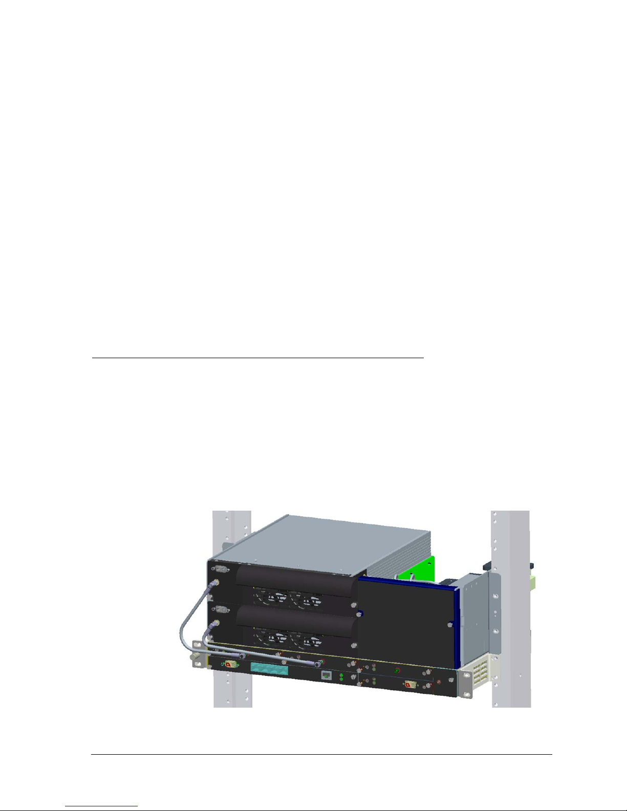
1. Fit the rack mounting brackets onto the chassis. Brackets can be mounted in either
a forward mount or a flush mount position.
2. Install the chassis. If installing multiple chassis, consider leaving a 3 RU space
between to allow for an expansion or extension kit(s).
3. Locate and secure RFU(s) and ACU in the chassis.
4. Connect the RFU(s) to the ACU using the supplied RF cables.
5. Using the supplied IF cable(s), connect the RFU(s) to the INU/INUe RAC 60 or
RAC 6x card(s). The minimum bend radius of the IF cable is 25mm (1”).
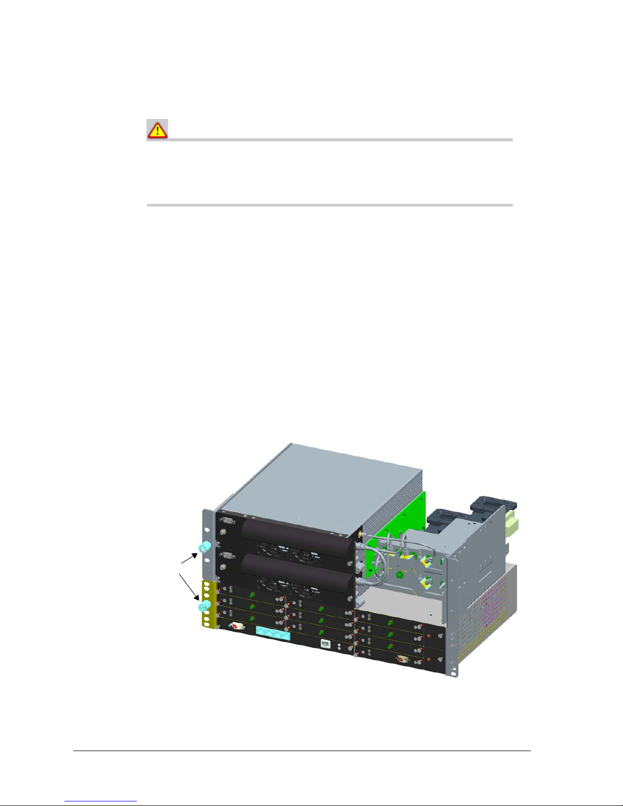
Figure 5-1. IRU 600 and INU
260-668066-003 Rev 001 August 2010 5-1
Page 40
Chapter 5. Installing the IRU 600
Ground
Ventilation Requirement
There must be a minimum of 50 mm (2”) of side spacing from the
INU/INUe to any rack panels, cable bundles or similar, and 50
mm (2”) of space to the front and back of the RF section to ensure
proper ventilation.
Grounding
The grounding stud as shown in Figure 5-2 will accommodate a wrist strap using the
jack at the front. It also will accommodate cable up to 16 mm
be threaded through the side holes and then secured by tightening the screw located on
the front of the grounding post. The grounding post is a pinned to prevent rotation.
1. Ground the IRU 600 from the grounding stud to the rack/frame ground bar using
a length of 4 mm
suitably sized crimp lug at each end (supplied by the installer).
For NEBS compliance, 16mm
is required together with a star washer under the grounding screw. Grounding post
screws must be torqued to 1.2-1.5 Nm (10-13 in-lbs).
2. If the equipment rack/frame requires grounding, use 16 mm
its ground bar to the station ground.
Figure 5-2. Grounding Point Detail
2
(AWG 12) green PVC insulated stranded copper wire with a
2
(AWG 6) green PVC insulated stranded copper wire
2
(AWG 6). The cable can
2
(AWG 6) wire from
5-2 Aviat Networks
Page 41

Eclipse Installation Manual
Safety Requirements for Equipment Grounding
1. Ground wires must provide a direct, low impedance path to the Master Ground bar
for the building, which should be located adjacent to the point of waveguide entry
to the building.
2. Do not connect other equipment to the same ground ing cable as the IRU 600. Each
item of equipment in a rack must be separately grounded to the rack ground bar.
The rack ground bar is then grounded directly to the building Master Ground.
3. The IRU 600 and INU must be located in the same immediate area (same or
adjacent racks/cabinets) as with any other equipment that is connected to the same
DC supply circuit point of grounding. DO NOT ground the INU and IRU 600
elsewhere.
4. All intra-building signal cabling must be shielded and both ends of each shield
must be grounded.
5. There shall be no switching or disconnecting devices in the grounded circuit
conductor between the DC source and the point of connection of the grounding
electrode conductor.
Waveguide Grounding
Grounding the waveguide is an essential part of the overall lightning protection sc heme
at the site. The number of waveguide grounds required is dependant on the antenna
height at its centerline. At a height of 45m, the minimum number of waveguide grounds
required is 3:
• One located at the top of the vertical waveguide run, about 1 meter below the bend
before the waveguide goes horizontal toward the antenna,
• One located at the bottom of the vertical cable run, about a meter above the bend
before the waveguide goes horizontal toward the equipment room entry point,
• One located at the equipment room entry way point.
The top and bottom ground is typical ly connected to a tower ground bar, or to the tower
steel using a ground clamp. The entryway ground should be attached to the ground bus
bar, generally located directly below the waveguide entryway point.
If the height of the antenna centerline is greater than 45m, then additional grounds are
required every 25m, or part of, above the 45m level. The topmost one should be located
about 1 meter below the bend before the waveguide goes horizontal toward the
antenna.
NEBS Compliance
For NEBS compliance:
• The equipment is to be grounded to a Common Bonding Network.
• All bare conductors must be coated with an appropriate antioxidant compound
before crimp connectors are fitted.
• All unplated connectors, braided strap, and bus bars must be brought to a bright
finish and then coated with an antioxidant before they are connected. This does not
apply to tinned, solder-plated, or silver-plated connectors and other plated
connection surfaces – but all must be clean and free of contaminants.
• All raceway fittings must be tightened to provide a permanent low-impedance path.
260-668066-003 Rev 001 August 2010 5-3
Page 42
Chapter 5. Installing the IRU 600
Connect Waveguide(s) to Antenna Ports(s)
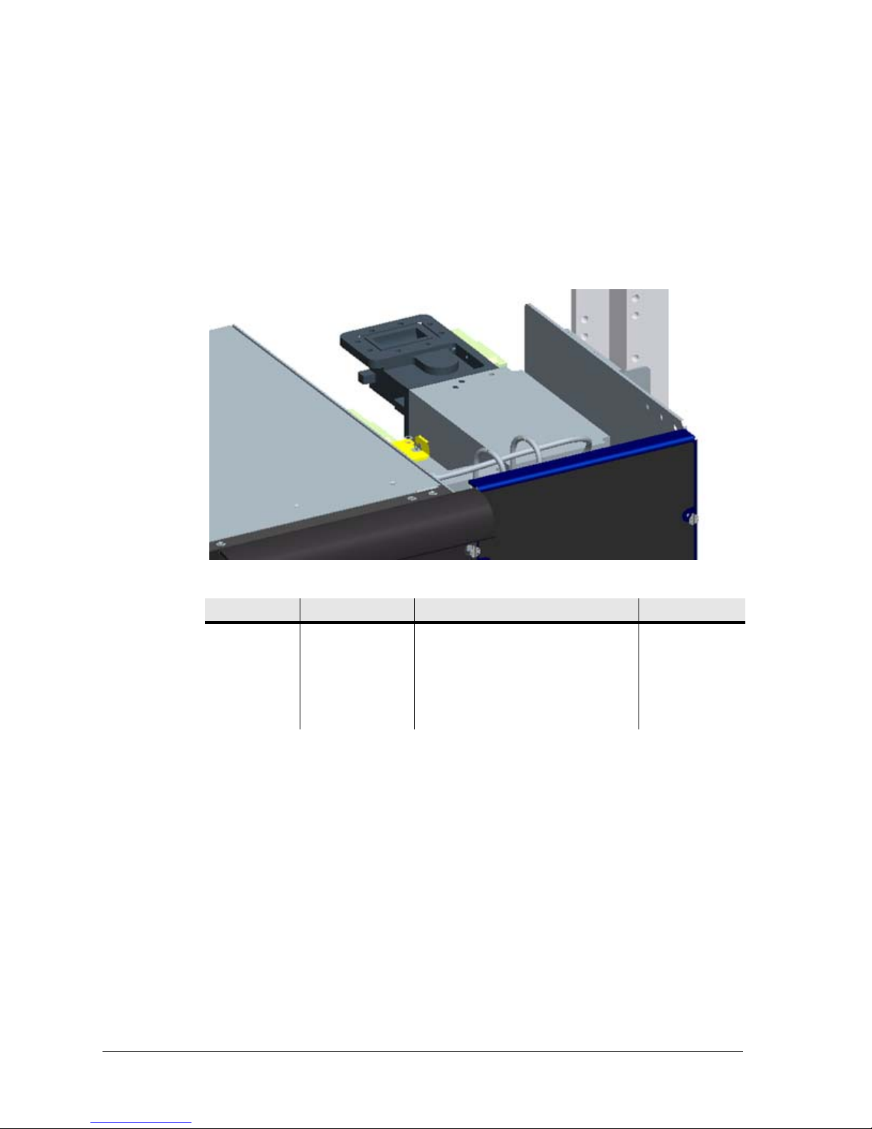
Connect the ACU antenna port(s) to the main waveguide(s) using appropriate lengths
of flexible waveguide.
For information on required waveguide flanges, and recommended waveguide type,
refer to Table 5-1.
Remove and discard any protective flange/port covers before installation.
Figure 5-3. ACU and Waveguide Connection
Table 5-1. Waveguide Flange Type
Freq, GHz Flange Type Holes Waveguide
6 • CPR 137 G • All open for # 6-32 screws • WR 137
7 • CPR 112 G • 8 x #10-32 t a pped holes • WR 112
8 • CPR 112 G • 8 x #10-32 t a pped holes • WR 112
10, 11 • CPR 90 G • 8 x #8-32 tapped holes • WR 90
Power Supply
Standard power RFUs are powered over the IF cable from its INU/INUe.
High power RFUs are additionally powered using a separate DC input on the RFU
front panel.
• The high power RFU provides a wide-mouth connection for +/- 21 to 60 Vdc. Both
+ve and -ve pins are isolated from chassis ground.
• The power connector (D-Sub M/F 2W2) and cable is identical to that used for the
INU. See Power Cables.
• Run the supplied power cable through to the power pick up point, which should
be protected by a circuit breaker or fuse in the rack. The circuit breaker or fuse
should have maximum capacity of 8 A.
• For a -48 Vdc supply, connect the blue wire to -48 Vdc (live), and the black wire
to ground/+ve.
5-4 Aviat Networks
Page 43

Eclipse Installation Manual
• For a +24 Vdc supply, connect the blue wire to +24 Vdc (live), and the black wire
to ground/-ve.
• For NEBS compliance the battery return connection is to be treated as an isolated DC
return (DC-I), as defined in GR-1089-CORE.
• An integral DC/DC converter provides polarity protection, under/over voltage
shutdown, over-current limit, and thermal shutdown.
• NEBS compliant EMI filtering is included.
• There are no serviceable fuses.
DC power connector can be shorted inadvertently if applied at an angle.
Always insert with correct alignment.
Next step: Install the INU/INUe.
260-668066-003 Rev 001 August 2010 5-5
Page 44

Chapter 5. Installing the IRU 600
5-6 Aviat Networks
Page 45

Chapter 6. Installing the INU and
INUe
The INU and the INUe are the Eclipse indoor units.
This chapter includes:
• INU/INUe Description
• INU/INUe Installation Requirements
• Plug-in Installation Requirements
•Installing an INU
For compliance information, refer to Compliance and Notices.
For health and safety information, refer to Health and Safety.
For information on installing an IRU 600, refer to Installing the IRU 600.
INU/INUe Description
The INU/INUe is a rack-mounted unit that pairs with one or more IRU 600s to mak e
an Eclipse node.
An INU/INUe comprises a chassis (IDC/IDCe) and plug-ins.
The IDC/IDCe has dedicated slots for the NCC and FAN plug-ins, and either four slots
(IDC) or ten slots (IDCe) available for optional RAC, DAC, AUX and NPC plug-ins. For
slot allocations and assignments, refer to .
Refer to:
•INU Front Panel Layout
•INU Power Supply
•Fuses
• FAN Air Filter Option
• Power Line Filter Option
INU Front Panel Layout
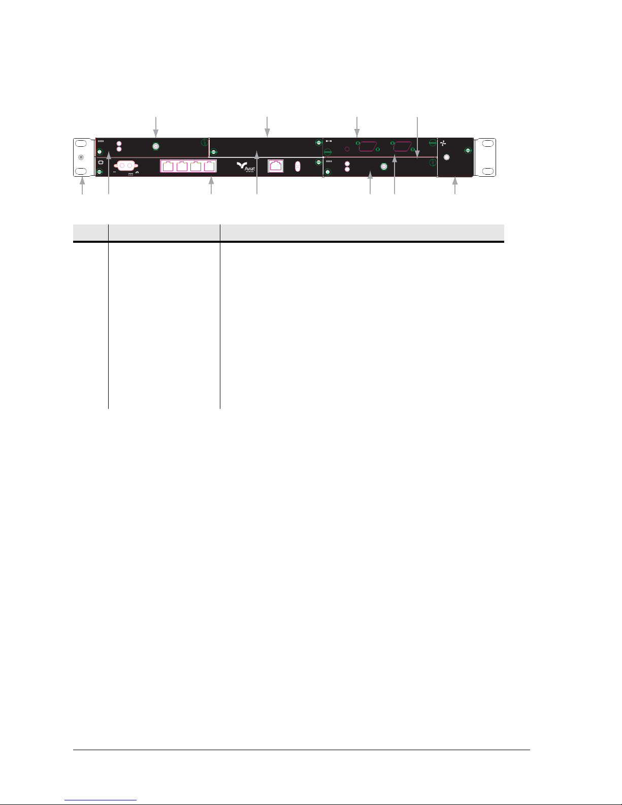
This figure is an example of an INU front panel, with one DAC 16x, two RACs, and a
blanking panel over the unused slot. For information on the plug-ins, refer to System
Overview.
260-668066-003 Rev 001 August 2010 6-1
Page 46
Chapter 6. Installing the INU and INUe
Fault
FAN
Fault
FAN
DAC 16x
Status
Trib 1-8 Trib 9-16
DAC 16x
Status
Trib 1-8 Trib 9-16
12
45
6
To
ODU
RAC 30
On-Line
Status
To
ODU
RAC 30
On-Line
Status
To
ODU
RAC 30
On-Line
Status
To
ODU
RAC 30
On-Line
Status
Slot 1 Slot 2 Slot 3
Slot 4
3
7
-48VDC
Figure 6-1. Typical INU Front Panel Layout
No Item/Label Description
1 Rack Ear and
grounding stud
Rack attachment bracket for the IDC. One ear has a
combined ESD and IDC grounding stud. The ears can be
fitted either side, which provide flush-with-rack-front
mounting.
2RAC RAC fitted in slot 1
3NCC Mandatory node Control Card (dedicated slot)
4Blank Panel Blanking panel fitted to slot 2
5RAC RAC fitted in slot 4
6DAC 16x 16xDS1 DAC fitted in slot 3
7FAN Mandatory fan plug-in (dedicated slot)
INU Power Supply
INUs require a -48 Vdc power supply (+ve earth), but will operate to specification over
a voltage range of -40.5 to -60 Vdc.
The return (+ve) pin on the NCC and NPC power supply connectors is clamped to
chassis ground via polarity-protecting power FETs.
• NCC and NPC power inputs are reverse polarity protected (the input fuse will not
blow if polarity is reversed).
For NEBS compliance the battery return connection is to be treated as a common DC
return (DC-C), as defined in GR-1089-CORE.
Where operation from a +24 Vdc PSU is required, the plug-in PCC option provides
voltage conversion from + 24 (19 to 36) Vdc to -56 Vdc for connection to the NCC
-48Vdc input. -56 Vdc represents a typical float voltage for a battery-backed -48 Vdc
supply.
The dc power supply must be UL or IEC compliant for SELV (Safety Extra Low Voltage)
output (60 Vdc maximum limited).
6-2 Aviat Networks
Page 47

Power Consumption and INU Load Maximums
Total power consumed is dependent on the number and type of plug-in cards, and the
number and type of IRU 600s.
• The number and type of RACs and DACs that can be installed in an INU are
determined by the load capacity and temperature limits of the DC converter in the
NCC, which supplies various DC rails to the plug-in cards.
• IRU 600s and FANs are not powered via the NCC converter. Their DC supply is
taken directly from the INU -48 Vdc power supply input connector.
• However, if a PCC is installed for +24 Vdc operation, the INU cards and associated
IRU 600s are supplied from the PCC, meaning PCC power limits are determined by
the INU cards and by the number of IRU 600s fitted.
Node Power Consumption
Table 2 lists nominal power consumption figures for Eclipse cards. Use these together
with the IRU600 consumption figures in the following t able to determine total nodal
power consumption.
Power consumption figures are for a -48 Vdc supply voltage at normal room ambients.
Table 2. Typical Plug-in Power Consumptions
Eclipse Installation Manual
Item Consumption
RAC 60 12W
RAC 6X 13W
DAC (Any variant) 3W
NCC 4W
NPC 4W
AUX 3W
FAN 1RU 2W
FAN 2RU 4W
Table 3 provides nominal figures for an IRU 600.
• For a standard power RFU, power is provided via its RAC - RFU cable.
• For a high power RFU, power is supplied via its RAC cable and additionally by a
front-mounted DC connector.
Table 3. Nominal IRU 600 Power Consumptions
Configuration Power Sourced
from INU
1+0 Standard Power (1xRFU) 52W N/A 52W
Power Sourced
from External DC
Connector
Total DC
Power
1+0 High Power (1xRFU) 52W 38W 90W
1+1 Standard Power (2xRFU) 82W N/A 82W
1+1 High Power (2xRFU) 82W 42W 124W
260-668066-003 Rev 001 August 2010 6-3
Page 48

Chapter 6. Installing the INU and INUe
Configuration Power Sourced
1+1 FD Standard Power (2xRFU) 104W N/A 104W
1+1 FD High Power (2xRFU) 104W 76W 180W
Node Card Maximums
The following guidelines should be used to determine maximum INU card/power
loadings for various node (INUe) configurations. Maximums are primarily determined
by operating temperature limits imposed on the DC converter modules in the NCC (and
NPC).
These card maximums apply up to the maximum ambient of 45
loadings may be permitted for lower ambients. Note that for cabinet-mounted INUs
the ambient temperature is the temperature within the cabinet.
INUe card loading maximums are:
• Five RAC 60 cards plus any three DACs
• Four RAC 6X cards plus any three DACs.
Note that:
• RACs should always be installed on the FAN side of the INU for best cooling
efficiency.
•A 2RU FAN
superior cooling compared to two 1RU FAN modules.
• Elevated ambient temperatures should be avoided. The 45
maximum must not be exceeded. Over-temperature operation is a primary factor
affecting long term component reliability.
Power Sourced
from INU
1
must always be used in an INUe with a high card loading. It provides
from External DC
Connector
o
o
C (112oF) ambient
Total DC
Power
C (112oF). Higher
PCC +24 Vdc Operation
The PCC is for use with standard +24 Vdc (-ve grounded) battery-backed power supply
systems. One PCC supports a maximum three IRU 600 RFUs, plus any combination of
RACs and DACs.
• The PCC +ve and -ve input terminals are isolated from chassis (ground). The -ve
input is grounded by the -ve grounded power supply connection.
• The PCC 20A fuse is fitted in the +ve input. It is a PCB mount type and is not field
replaceable.
• Reverse polarity protection is provided. The PCC will automatically recover from a
reverse polarity connection - the fuse will not blow. Over temperature thermal
protection is included.
• The PCC load maximum is 200 Watts. Use the power consumption data in the
preceding section to determine the maximum number of cards and RFUs that can be
supported.
• The PCC conversion efficiency is nominally 10%. To determine the power cons umed
by the PCC, use a figure of 10% of the power consumed by the INU/INUe cards and
IRU 600 RFUs.
1
A 2RU FAN is standard with an INUe, but an INUe can be fitted with two 1RU FANs.
6-4 Aviat Networks
Page 49
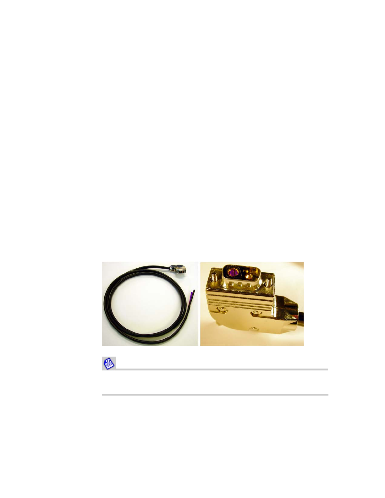
• When installed in an INUe, the INUe must be fitted with the 2RU FAN module as it
provides almost double the air flow of two 1RU FAN modules.
• The PCC should always be installed next to the FAN card to get best air flow cooling.
• The PCC must be connected to the NCC before applying power to the PCC to avoid a
current-inrush trip (overload) on the PCC.
• The PCC can be plugged into any INU/INUe option slot. It is not connected to the
backplane and is its function is not monitored within Portal.
• Where an NPC is fitted, two PCCs are required for +24 Vdc operation, one for the
NCC, the other for the NPC. This means an INUe must be used for NCC + NPC
operation.
• If the PCC front-panel LED is not lit, it indicates the existence of abnormal
conditions such as output under-voltage, output over-voltage, loss of input power,
output over-current, or open input fuse.
Power Cables
The INU power cable is included in the IDC Installation Kit. It is supplied with a D-sub
M/F 2W2 connector fitted at one end and wire at the other. The cable is nominall y 5 m
(16 ft), and the wires are 4 mm
2
(AWG 12).
Eclipse Installation Manual
The cable is used for -48 Vdc connections to an NCC or NPC, or for +24 Vdc
connections to a PCC.
The blue wire must be connected to live (-48 Vdc or +24 Vdc); the black wire to ground
(+48 Vdc or -24 Vdc).
Figure 6-4. Power Cable and Connector
DC power connector can be shorted inadvertently if applied at an angle.
Always insert with correct alignment.
The PCC is supplied with a power cable to connect to an NCC or NPC.
Similarly, the power line filter unit is supplied with a power cable to connect to an NCC,
NPC, or PCC.
260-668066-003 Rev 001 August 2010 6-5
Page 50
Chapter 6. Installing the INU and INUe
This cable is fitted with a D-sub M/F 2W2 connector at each end. Note that a standard
power cable is not included for the reason the cable supplied with an NCC (or NPC) is
not used when powered from a PCC, or via a power line filter, so the cable is re-used as
the power input cable for the PCC or filter unit.
Fuses
The NCC and NPC are fitted with a fast-acting 25 A fuse fitted on the PCB behind the
power cable connector.
The PCC is fitted with a fast-acting PCB-mounted 20A fuse.
NCC, NPC and PCC fuses are not field-replaceable.
FAN Air Filter Option
A fan air filter option is available for installation with the FAN module in an INU, and
with the 2RU FAN module in an INUe. Where Eclipse is required to be NEBS (Network
Equipment-Building System) compliant, the fan air filter must be installed.
The fan air filter must be inspected regularly and replaced when dust
laden. In normal telecommunications equipment -room environments
inspection must be at not more than 12 monthly intervals. In other
environments where air quality is not controlled, more frequent
inspection is required.
A heavily dust-laden filter will severely restrict fan air flow and
may lead to over-heating.
Excessive heat is the number one cause of premature equipment
aging and failure.
To maximize long term component reliability, the fan air filter
must not be allowed to become clogged, and ambient
temperature limits must not be exceeded.
Fan Air Filter Installation
The fan air filter kit comprises a filter frame, filter element, and fastening screw. It is
installed in the INU/INUe to the right side of the FAN module, as illustrated in Figure
6-5 for an INUe.
1. Remove the FAN module and slide the air filter into the chassis so that it locates to
the right side of the FAN module backplane connector, and up against the chassis
side.
6-6 Aviat Networks
Page 51
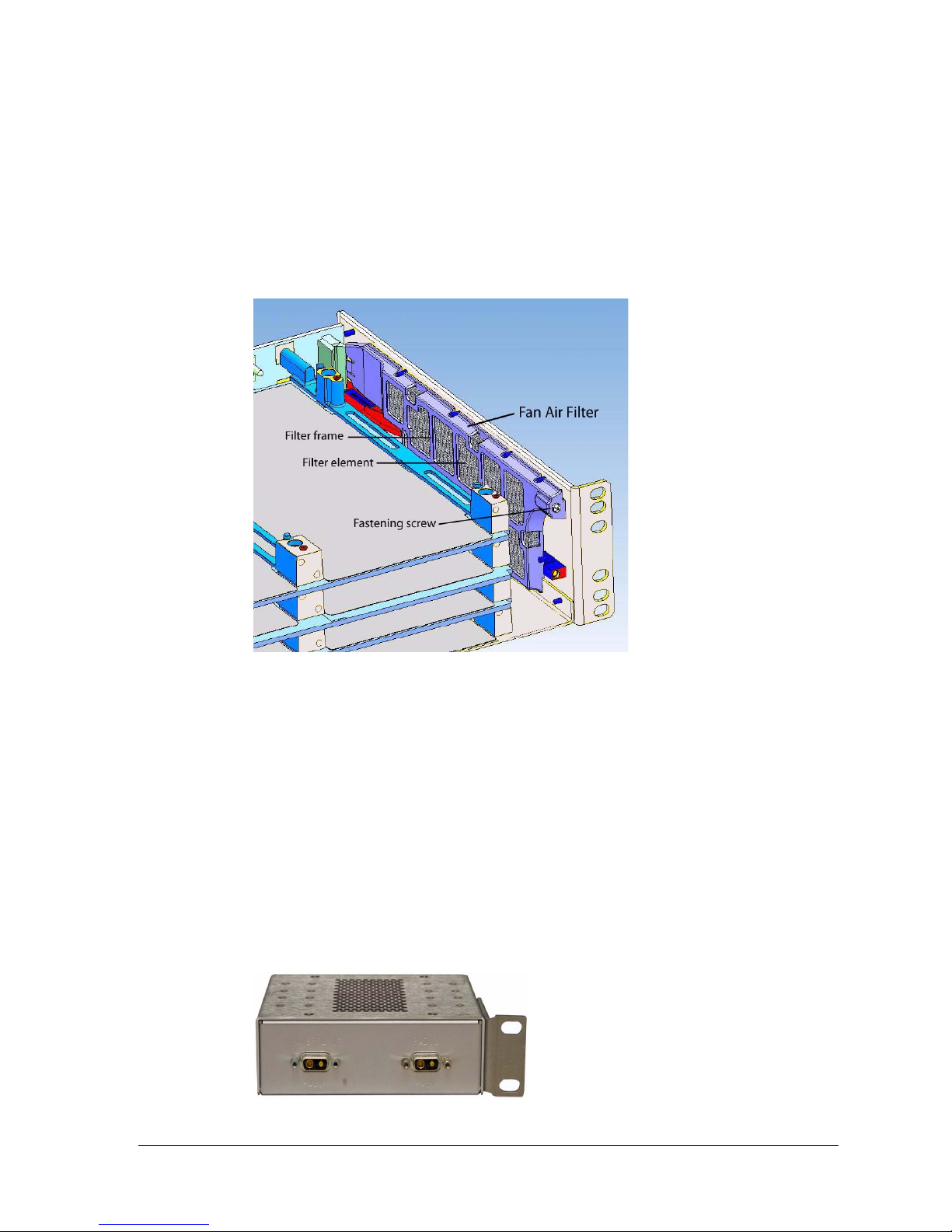
Eclipse Installation Manual
FAN module removal and replacement does not affect INUe traffic.
2. Fasten in place using the screw supplied. Do not over-tighten - the screw is
designed to bite into the unthreaded hole provided in the plastic frame.
3. Replace the FAN module.
Installation instructions are included with the fan filter kit.
Figure 6-5. Location of Fan Air Filter in INUe
Power Line Filter Option
An external DC power line filter option is available and must be installed with an INU/
INUe for NEBS compliance. It ensures Eclipse meets EMI requirements specified
within Telcordia GR-1089-CORE, Issue 4, June 2006.
It is 1RU tall and 140mm wide (5.5”), and is supplied as a kitset comprising the filter
unit, bracket for left or right side rack mounting, and a short 2W2-to-2W2 cable for
connecting the filter unit to the NCC or NPC -48 Vdc inputs.
• Where an NPC is fitted, two filter units are required, one for the NCC, the other for
the NPC.
• The standard power cable supplied with an INU or NPC is re-used as the power input
cable for the filter unit.
Figure 6-6. Power Line Filter with Bracket
260-668066-003 Rev 001 August 2010 6-7
Page 52

Chapter 6. Installing the INU and INUe
INU/INUe Installation Requirements
Table 6-1. INU Installation Requirements
Function/Requirement Details
Restricted access The INU/INUe and its associated dc power supply must be installed
in a restricted access area such as a secure equipment room, closet,
or cabinet.
For NEBS compliance, this equates to installation of the INU/INUe in
a secure, restricted access central office (CO) or customer premises
(CP) location.
Required Rack Space The INU requires 44.5 mm (1RU) of vertical rack space and
300 mm rack depth. The INUe requires 89mm (2RU) vertical rack
space.
Ventilation The INU/INUe requires unobstructed air passage to each side for
ventilation purposes. There must be a minimum of 50 mm (2”) of
side spacing to any rack panels, cable bundles or similar. No space
above or below is required for ventilation purposes.
Fan Air Filter The fan air filter must be installed where the INU/INUe is requir e d
to be NEBS compliant. The filter must be inspected regularly and
replaced when dust laden. Inspection must be at not more than 12
monthly intervals in controlled air environments, or more
frequently otherwise.
Power Line Filter The power line filter must be installed where the INU/INUe is
required to be NEBS compliant.
Maximum Ambient
Temperature
Physical stability Ensure that adding an INU/INUe to a rack does not adversely
Power supply -48 Vdc The INU (NCC and NPC) has the +ve pin on its dc power supply
The INU/INUe is specified for a maximum ambient temperature
(Tmra) of +45° Celsius (113° Fahrenheit). The maximum ambient
temperature (Tmra) of +45° Celsius applies to the immediate
operating environment of the INU, which if installed in a rack, is the
ambient applying to its location within the rack.
impact the physical stability of the rack.
connector connected to the chassis.
It must be used with a -48 Vdc power supply which has a +ve
ground; the power supply ground conductor is the +ve supply to
the INU.
There must be no switching or disconnecting devices in the ground
conductor between the dc power supply and the point of connection
to an INU/INUe.
For NEBS compliance the battery return connection is to be treated
as a common DC return (DC-C), as defined in GR-1089-CORE.
6-8 Aviat Networks
Page 53

Eclipse Installation Manual
Function/Requirement Details
Power Supply +24 Vdc A PCC is required to provide a +24 Vdc to -48 VDC conversion. The
dc power supply supplying the PCC must be -ve grounded.
There must be no switching or disconnecting devices in the ground
conductor between the dc power supply and the point of connection
to a PCC.
Power Supply Location The INU/INUe must be installed in the same premises as its dc
power supply and be located in the same immediate area (such as
adjacent racks or cabinets) as any other equipment that is
connected to the same dc power supply.
Power Supply Compliance
and Loading
Cable routing Eclipse tributary, auxiliary and NMS cables are not to be routed with
Grounding The INU must be grounded to the station or master ground, which
Intrabuilding interfaces
and cabling
(NEBS Compliance)
The dc power supply must be UL or IEC compliant for a SELV output
(60 Vdc maximum).
Check to ensure that connection of an Eclipse system to an existing
dc supply does not overload the supply, circuit protection devices
and wiring.
Where a new dc power supply is to be installed for an Eclipse Node,
the power supply should be rated to supply:
• 12.5 A for the INU
•25A for the INUe
•15A for the PCC
any AC mains power lines. They are also to be kept away from any
power lines which cross them.
must be the same ground as used for the dc power supply. Normally
this is achieved by grounding the INU to the ground bar in its
equipment rack or frame. This bar is most often located to one side
of the rack or at rack top or bottom. In turn, the ground bar is
grounded to the station ground.
Intrabuilding connections to/from Eclipse ports must only be
connected via intrabuilding or unexposed wiring or cabling.
Intrabuilding ports MUST NOT be metallically connected to
interfaces that connect to the OSP or its wiring. These interfaces are
designed for use as intrabuilding interfaces only (Type 2 or Type 4
ports as described in GR-1089-CORE, Issue 4) and require isolation
from the exposed OSP cabling. The addition of Primary Protectors
is not sufficient protection in order to connect these interfaces
metallically to OSP wiring.
Shielded and grounded cables must be used for intrabuilding
cabling to/from Eclipse ports. Cables must be grounded at both
ends.
260-668066-003 Rev 001 August 2010 6-9
Page 54
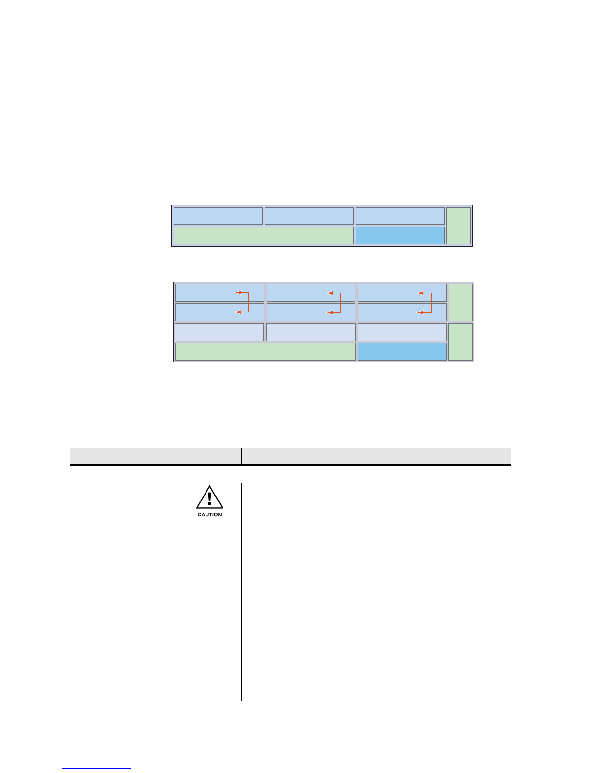
Chapter 6. Installing the INU and INUe
INU
INUe
Plug-in Installation Requirements
The IDC has four universal slots and two dedicated slots. The IDCe has six universal
slots, three restricted slots and 4 dedicated slots. A populated IDC/IDCe is called an
INU/INUe.
Figure 6-7. Slot Numbering for INU and INUe
Slot 1
NCC
Slot 2
Slot 3
Slot 4
Fan
Slot 1
Slot 4
Slot 7
NCC
Slot 2
Slot 5
Slot 8
Slot 3
Slot 6
Slot 9
Slot 10
Fan
Fan
Installing or changing out a plug-in is a straightforward process. The requirements are
detailed in Table 6-2.
Unless specified by the customer, plug-ins will not be installed in an INU/INUe at
shipment. Instead, each is individually packed within the shipping box.
Table 6-2. Plug-in Requirements
Function/Requirement Priority Details
Slot Assignment
All slots filled All slots must be filled with either a plug-in or a blanking
panel. Failure to do so will compromise EMC integrity and
distribution of FAN cooling air.
Universal slots
1-4 on an INU
1-6 on an INUe
RAC, DAC, and AUX plug-ins can be fitted in any universal
slot.
Restricted slots
7-9 on an INUe
Dedicated slots The NCC, FAN, and NPC plug-ins have dedicated slots.
Protected RACs INUe Protected RACs (or ring-protected RAC with DAC 155oM)
AUX Multiple AUX plug-ins can be installed per INU/INUe.
6-10 Aviat Networks
DAC, and AUX plug-ins can be fitted in any restricted slot.
The exceptions are the DAC 155oM and AUX, which must
only be installed in slots 1 to 6 when they are to be
configured to carry/access Eclipse NMS, otherwise they can
be installed in slots 7 to 9.
must only be installed in ‘above and below’ slots as
indicated by the red arrows.
Page 55
Eclipse Installation Manual
Function/Requirement Priority Details
NPC Only one NPC is required to provide the NCC protection
option. An NPC must be installed in slot 4 of an INU, or slot
10 of an INUe. If an NPC is not installed in an INU, slot 4 is
available as a universal slot.
Installing / Changing Plug-ins
ESD grounding strap Always connect yourself to the INU/INUe with an ESD
grounding strap before changing or removing a plug-in.
Failure to do so can cause ESD damage to the plug-ins.
Avoid hand contact with the PCB top and bottom.
Finger-grip fasteners Plug-ins must be withdrawn and inserted using their
finger-grip fasteners/pulls. Never withdraw or insert using
attached cables, as damage to the plug-in connector and
its PCB attachment can occur. If not complied with, the
Aviat Networks warranty may be voided.
Hot-swappable Plug-ins are hot-swappable.
• Removal of an in-service payload plug-in will interrupt its
traffic.
• Removal of the NCC will affect all traffic - unless
protected by an NPC.
• Removal / replacement of the FAN does not affect traffic.
Engaging backplane
connector
When installing a plug-in, ensure its backplane connector
is correctly engaged before applying sufficient pressure to
bring the plug-in panel flush with the front panel.
Revision time lag When swapping or installing plug-ins, up to 60 seconds can
be required for the INU/INUe to show its revised status via
the front panel LEDs, or via Portal.
EMC integrity Plug-ins and blanking panels are held in place by captive
finger-screws. Ensure the finger-screws are fastened as
failure to do so may compromise EMC integrity and fan
cooling.
RACs
Connecting and
disconnecting the RFU
cable at the RAC
Removing RAC from a
powered INU
Never disconnect or reconnect an RFU cable to a RAC
without first turning the power off to the INU or
withdrawing the RAC from the backplane.
Note: The RFU cable provides the power feed to the IRU 600.
Arcing during connection and disconnection at the RAC
on a live RAC can cause damage to connector contact
surfaces. Power spikes caused by live connection and
disconnection may also cause errors on other traffic
passing through the INU/INUe. The only exception to
live disconnection and connection should be for checks
of protected operation at link commissioning.
When removing a RAC from a powered INU, always the
disengage the RAC from the backplane before
disconnecting its RFU cable. Similarly before inserting an
RAC, always reconnect the RFU cable before engaging the
backplane.
260-668066-003 Rev 001 August 2010 6-11
Page 56
Chapter 6. Installing the INU and INUe
Function/Requirement Priority Details
RAC combinations for
INUe
DACs
DAC combinations DACs can be fitted singly or in combination to provide a mix
Increasing node capacity To achieve a greater node capacity, two or more INUs can
DAC 16x Mini RJ-21trib
cable connector
An INUe can be fitted with a maximum of:
• Five RAC 60s.
•Four RAC 6Xs.
(The reduced RAC numbers are to ensure temperature
limits within the INUe are not exceeded at high ambients.
See Node Card Maximums.)
of interface types and capacities provided they have a
common backplane configuration. The backplane can be
set for 1.5 Mbps/DS1, 43 Mbps/DS3, or 155 Mbps/OC3.
TDM Mux DACs allow a mix of interfaces from a common
DS1 backplane configuration.
be interconnected via a DAC option.
Ensure correct orientation of the Mini RJ-21 connector on
DAC 16x before pushing it home. This can be checked by
the scalloped key to one side of the connector. Additionally,
a trib cable supplied by Aviat Networks will have the cable
exiting to the right side when viewed from the front.
Ensure the connector retaining screws are not
over-tightened - only use light/moderate screwdriver
pressure.
Line Protection (electrical
DACs)
Line Protection (optical
DACs)
General
Maximum Backplane
Capacity of Eclipse Node
Antistatic bags Enclose spare plug-ins, or plug-ins to be returned for
Spare blank panels Keep any removed blanking panels for future use.
Line (interface) protection can be provided for paired DS3
and STS3 electrical DACs.
Line (interface) protection can be provided for paired OC3
optical DACs.
The maximum drop, through plus drop, or through
backplane capacity on an Eclipse Node is one of the
following, depending on the backplane setting:
• 300 Mbps
• 128xDS1
•6xDS3
•2xOC3
service, in an antistatic bag. When handling a plug-in to or
from an antistatic bag, do so at the INU/INUe and only
when you are connected to the INU/INUe via an ESD
ground strap.
6-12 Aviat Networks
Page 57

Installing an INU
Procedure
1. Fit the rack mounting ears to the chassis with the grounding stud to left or right side
for the most direct ground wire path to the rack ground bar.
2. Locate the INU/INUe in the equipment rack and secure it using four No.12 Phillips
dome-head screws from the IDC installation kit.
3. Where NEBS compliance is required, install the power line filter unit. Install
immediately below or above the INU. Separate filter units are required for the NCC
and, where fitted, the NPC. Use the supplied 2w2 to 2w2 cable to connect the
output of the filter unit to the input of the NCC or NPC.
4. Ground the INU/INUe from the grounding stud to the rack/frame ground bar
using a length of 4 mm
a suitably sized ground lug at each end (supplied by the installer).
•For NEBS compliance, 16 mm
wire is required together with a star washer under the grounding screw. Torque
the INU grounding post screw to 1.2-1.5 Nm (10-13 in-lbs).
5. If the equipment rack/frame requires grounding, use 16 mm
its ground bar to the station ground.
Eclipse Installation Manual
2
(AWG 12) green PVC insulated stranded copper wire with
2
(AWG 6) green PVC insulated stranded copper
2
(AWG 6) wire from
Do not assume that an existing rack or mounting frame is correctly
grounded. Always check the integrity of the ground connections, which
must include a check through to the master ground for the station, which
should be located at the point of cable entry to the equipment building.
For NEBS compliance:
- All bare conductors must be coated with an appropriate antioxidant
compound before crimp connectors are fitted.
- All unplated connectors, braided strap, and bus bars must be brought
to a bright finish and then coated with an antioxidant before they are
connected. This does not apply to tinned, solder-plated, or silv er- plat ed
connectors and other plated connection surfaces – but all must be clean
and free of contaminants.
- All raceway fittings must be tightened to provide a permanent
low-impedance path.
6. Install the plug-ins in their assigned slot positions, and check that their front panels
are flush-fitted (not protruding) and held secure by their fasteners. Ensure unused
slots are covered by blanking panels. Refer to .
260-668066-003 Rev 001 August 2010 6-13
Page 58

Chapter 6. Installing the INU and INUe
Where a fan air filter is to be installed, install it prior to installing the FAN plug-in.
7. Install the CompactFlash card in the NCC plug-in; withdraw the NCC and insert in
the socket on the right side of the PCB.
8. Fit the IF cable between the RAC(s) and IRU 600 RFU(s). IF cables are supplied
with the IRU 600.
Fit the DAC tributary cables.
For a DAC 16x, ensure correct orientation of the Mini RJ-21 connector
before pushing it home. This can be checked by the scalloped key to one
side of the connector . Additional ly, a trib cable supplied by Aviat Networks
will have the cable exiting to the right side when viewed from the front.
Do NOT over-tighten the Mini RJ-21 retaining screws.
The following steps describe the procedure for preparing the power cable, and
preparing for power-on. Do not connect the power until all steps have been
completed.
9. Run the supplied power cable through to the power pick up point, which will
normally be at a circuit breaker panel in the rack. A circuit breaker (or fuse) should
have a capacity of 12 A for the INU and 25 A for the INUe.
10. For a -48 Vdc supply, connect the blue wire to -48 Vdc (live), and the black wire to
ground/+ve. (Power input on the NCC and NPC is polarity protected).
11. For a +24 Vdc supply, connect the blue w ire to+24 Vdc (live), and the black wire to
ground/-ve. (Power input on the PCC is polarity protected).
12. Measure the volt age on the dc power connector.
• For -48 Vdc operation the voltage should be -48 Vdc, +/-2 Vdc for a non battery
floated supply, and nominally -56 Vdc for a battery floated supply. (Limits are
-40.5 to - 60 Vdc).
• For +24 Vdc operation the voltage should be 24 +/- 2 Vdc for a non battery floated
supply, and nominally 30 Vdc for a battery floated supply. (Operating limits are
20 to 36 Vdc).
This product meets the global product safety requirements for SELV
(safety extra-low voltage) rated equipment and the input voltage must
be guaranteed to remain within the SELV limits (60 V maximum) in the
event of a single internal fault.
Always check the integrity of the dc power supply to an INU/INUe right
to its source. Never assume that the supply provided to the pick-up point
in a rack is correct.
6-14 Aviat Networks
Page 59

Eclipse Installation Manual
Eclipse dc power, IF, tributary, auxiliary and NMS cables are not to be
routed with any AC mains power lines. They are also to be kept away
from any AC power lines which cross them.
13. Carry out a complete check of the installation. If all is correct, and the IRU 600 and
its waveguide, pressurization and antenna installation has likewise been completed
and checked, Eclipse is now ready for power-on. If a PCC is installed, ensure
the PCC to NCC/NPC cable is fitted before power-on.
Once powered up the RFU(s) will be transmitting with the pre-configured or
ex-factory frequency and power settings unless the start-up transmit mute
option has been invoked. (All RFUs shipped ex-factory have the
transmit-mute set as the default unless otherwise specified).
If frequency and power settings are not correct, interference can be caused
to other links in the same geographical area.
14. Power on for -48 Vdc by connecting the power cable to the NCC, and to the NPC
where fitted.
• For +24 Vdc operation, connect to the PCC input.
• Where a power line filter is installed (for -48 Vdc), connect to the filter input.
The 2W2 DC power connector can be shorted inadvertently if
applied at an angle. Always insert with correct alignment.
Next step: The Eclipse node is ready for configuration and antenna alignment.
260-668066-003 Rev 001 August 2010 6-15
Page 60

Chapter 6. Installing the INU and INUe
6-16 Aviat Networks
Page 61

Page 62

260-668066-003
WWW.AVIATNETWORKS.COM
 Loading...