

Page 1
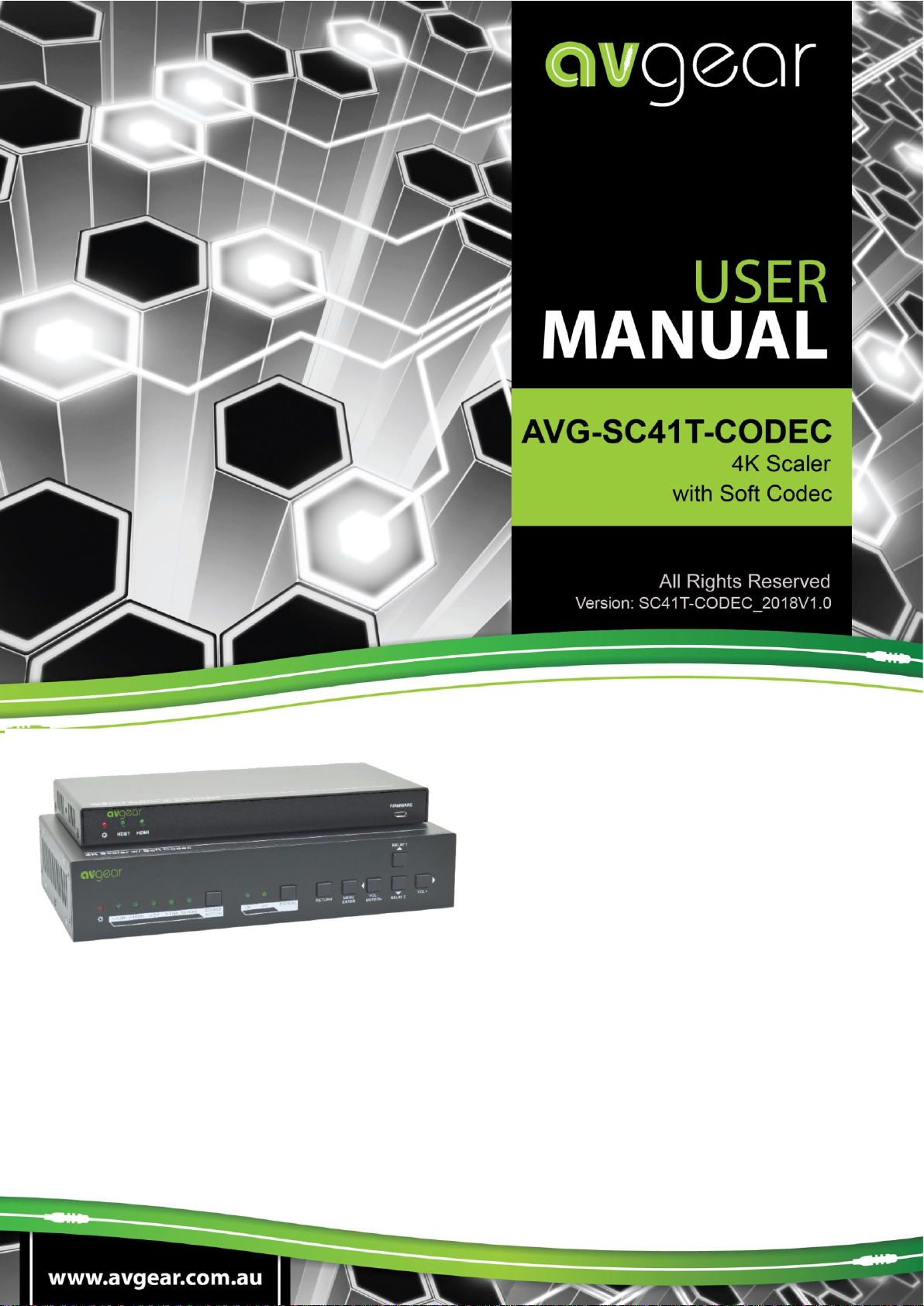
AVG-SC41T-CODEC
Features
Supports resolution conversion
ranging from 720p to 4Kx2K@30Hz
4:4:4
Provides a variety of interfaces to
simplify room device management.
Supports PCs, USB devices such as
keyboard, webcam, Mic for
Conferencing system.
Extends the transmission distance
of USB signals.
Supports Auto-switching for inputs.
HDBaseT technology extends
Video, Audio, Control and Ethernet
up to 100m.
De-embedded Analogue Audio.
CEC control of connected Display.
Controllable relays for Projector
screens or lifts.
Local Input available on the
Receiver for BYOD (sold
separately).
The AVG-SC41T-Codec is a conferencing system
codec kit supporting resolutions up to 4K@30Hz
4:4:4 and HDCP2.2. It includes a Transmitter and
Receiver, providing AV Switching, de-embedded
Audio, System Control commands and USB
Extension.
Video, Audio, Control, USB and Ethernet signals
can be transmitted over a single CATx cable up to
100m.
Page 2

AVG-SC41T-CODEC
PLEASE READ THIS PRODUCT MANUAL CAREFULLY
BEFORE USING THIS PRODUCT.
This manual is only for operational instruction only,
and not to be used for maintenance. The functions
described in this version are current as at January
2018. Any changes of functions and operational
parameters will be updated in future manual versions.
Please refer to your dealer for the latest product
details.
Version 1.0 31/1/18
Page 3

AVG-SC41T-CODEC
SAFETY OPERATION GUIDE
To guarantee the reliable operation of the equipment and safety of the user,
please abide by the following procedures in installation, use and maintenance:
1. The system must be earthed properly. Please do not use two blade plugs
and ensure the alternating power supply ranges from 100v to 240v and from
50Hz to 60Hz.
2. Do not install the switcher in an environment where it will be exposed to
extreme hot or cold temperatures.
3. This unit will generate heat during operation, please ensure that you allow
adequate ventilation to ensure reliable operation.
4. Please disconnect the unit from mains power if it will be left unused for a
long time.
5. Please DO NOT try to open the casing of the equipment, DO NOT attempt to
repair the unit. Opening the unit will void the warranty. There are high
voltage components in the unit and attempting to repair the unit could result
in serious injury.
6. Do not allow the unit to come into contact with any liquid as that could result
in personal injury and product failure.
Page 4

AVG-SC41T-CODEC
TABLE OF CONTENTS
Introduction .............................................................................................................. 1
Introduction to AVG-SC41T-CODEC ............................................................ 1.1
Features ....................................................................................................... 1.2
What’s in the Box .......................................................................................... 1.3
Panel Description ..................................................................................................... 2
Transmitter ................................................................................................... 2.1
Receiver ....................................................................................................... 2.2
System Connection .................................................................................................. 3
Usage Precautions ....................................................................................... 3.1
System Diagram ........................................................................................... 3.2
Operation .................................................................................................................. 4
Front Panel Controls ..................................................................................... 4.1
Manual Switching ............................................................................ 4.1.1
Auto Switching ................................ ................................................ 4.1.2
Volume Control ............................................................................... 4.1.3
RS232 Control .............................................................................................. 4.2
Installation/Removal of RS232 Control Software ............................ 4.3.1
Basic Settings ................................................................................. 4.3.2
RS232 Control Commands ............................................................. 4.3.3
OSD Menu Control ....................................................................................... 4.4
Picture Menu Item ........................................................................... 4.4.1
Setup Menu Item ............................................................................ 4.4.2
Web Based GUI Control ............................................................................... 4.5
Control Menu .................................................................................. 4.5.1
Configuration Menu ........................................................................ 4.5.2
RS232 Control Menu ...................................................................... 4.5.3
Password Menu .............................................................................. 4.5.4
Web Based GUI Update ................................................................. 4.5.5
Specifications ........................................................................................................... 5
Panel Drawing .......................................................................................................... 6
Troubleshooting & Maintenance ............................................................................. 7
Page 5

AVG-SC41T-CODEC
1. Introduction
1.1. Introduction to AVG-SC41T-CODEC
The AVG-SC41T-Codec is a conferencing system codec kit supporting resolutions
up to 4K@30Hz 4:4:4 and HDCP2.2. It includes a Transmitter and Receiver,
providing AV Switching, de-embedded Audio, System Control commands and USB
Extension. Video, Audio, Control, USB and Ethernet signals can be transmitted over
a single CATx cable up to 100m.
The kit provides four Video inputs such as HDMI, VGA and DP. To help simplify
meeting room device management, the kit offers LAN connections for Ethernet and
USB ports for device extension, four on the Transmitter and two on the Receiver. It
supports a variety of USB2.0 devices such as Cameras, Microphones and
keyboards. It supports many other HID devices.
Users can control system functionality via WEB GUI, RS232 and CEC. Users also
have control over the relay ports for projector screen or lifts.
It’s a versatile solution for use in education institutions, meeting rooms, conference
rooms using PC-based conferencing system codecs such as Skype, WebEx and
GoToMeeting.
1.2. Features
Supports resolution conversion ranging from 720p to 4Kx2K@30Hz 4:4:4
Provides a variety of interfaces to simplify room device management.
Supports PCs, USB devices such as keyboard, webcam, Mic for Conferencing
system.
Extends the transmission distance of USB signals.
Two USB B ports used to connect to the host and four USB A for HID devices
such as Webcam, mic and keyboard.
Supports Auto-switching for inputs.
HDBaseT technology extends Video, Audio, Control and Ethernet up to 100m.
Ethernet can be used from either the Transmitter or Receiver, providing easy
LAN access to users.
De-embedded Analogue Audio.
CEC control of connected Display.
Ensures EDID communication between sources and display.
Controllable relays for Projector screens or lifts.
Local Input available on the Receiver for BYOD (sold separately).
Page 6

AVG-SC41T-CODEC
1.3. What’s in the Box
1 x AVG-SC41T-Codec-T Transmitter and 1 x AVG-SC41T-Codec-R Receiver
4 x Mounting Ears, and 6 screws
8 x Rubber feet
1 x RS232 cable (3 pin phoenix connector to DB9)
1 x 7 pin phoenix connector
1 x 5 pin phoenix connector
1 x Power Adapter (24VDC, 2.71A)
1 x User Manual
Note: Please confirm if the product and the accessories are all included, if not,
please contact with the dealers.
Page 7
AVG-SC41T-CODEC
2. Panel Description
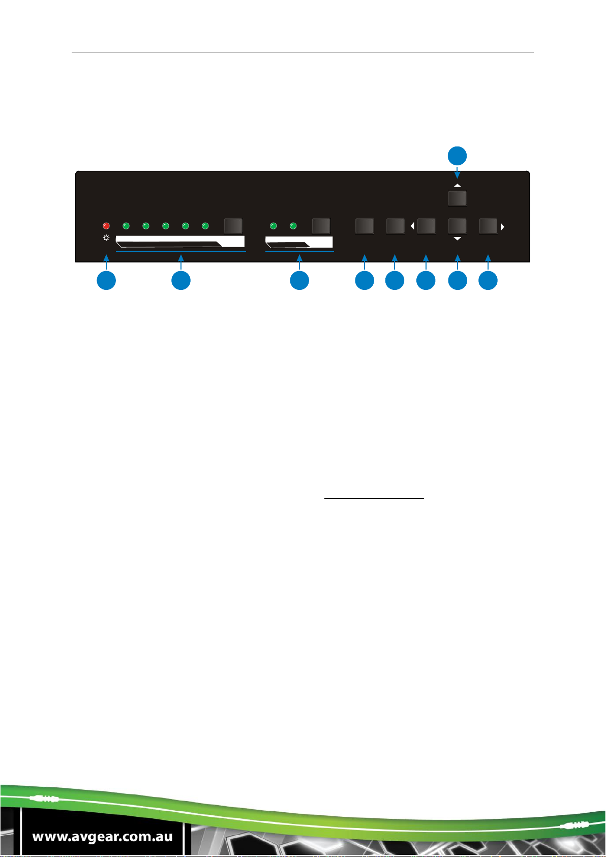
2.1. Transmitter Front Panel
① POWER LED: The LED illuminates red when power is applied, or orange when
the auto-switching mode is selected.
② INPUT LED & SOURCE SELECTOR:
1-HDMI: The LED illuminates green when 1-HDMI input signal is selected.
2-HDMI: The LED illuminates green when 2-HDMI input signal is selected.
3-DP: The LED illuminates green when 3-DP input signal is selected.
4-VGA: The LED illuminates green when 4-VGA input signal is selected.
RX HDMI: The LED illuminates green when the HDMI input signal on Receiver
is selected.
SOURCE SELECTOR: Press this button to select the source signal, or long-
press for 3 seconds or more to enable auto-switching mode.
For more details, please refer to section 4. Button Control.
③ DISPLAY CONTROL: Press this button to toggle power to the displays. The LED
will illuminate green to reflect the state.
④ RETURN: Return key used for the OSD.
⑤ MENU / ENTER: Menu or Enter key for OSD.
⑥ VOL - / MUTE: Press this button to turn down the audio output volume, or long-
press 3 seconds or more to mute / Left key for OSD.
⑦ RELAY 1: Press this button to roll up the projection screen. / Up key for OSD.
⑧ RELAY 2: Press this button to drop the projection screen. / Down key for OSD.
⑨ VOL +: Press this button to turn up the audio output volume. / Right key for OSD.
Note: Pictures shown in this manual are for reference only, different model and
specifications are subject to real product.
RX HDMI SOURCE
AUTO/3s
1-HDMI 2-HDMI 4-VGA3-DP
OFF DISPLAYON
MENU
ENTER
RETURN
RELAY 1
VOL +
VOL -
MUTE/3s
RELAY 2
1
2
3
4
5
6
8
7
9
Page 8
AVG-SC41T-CODEC
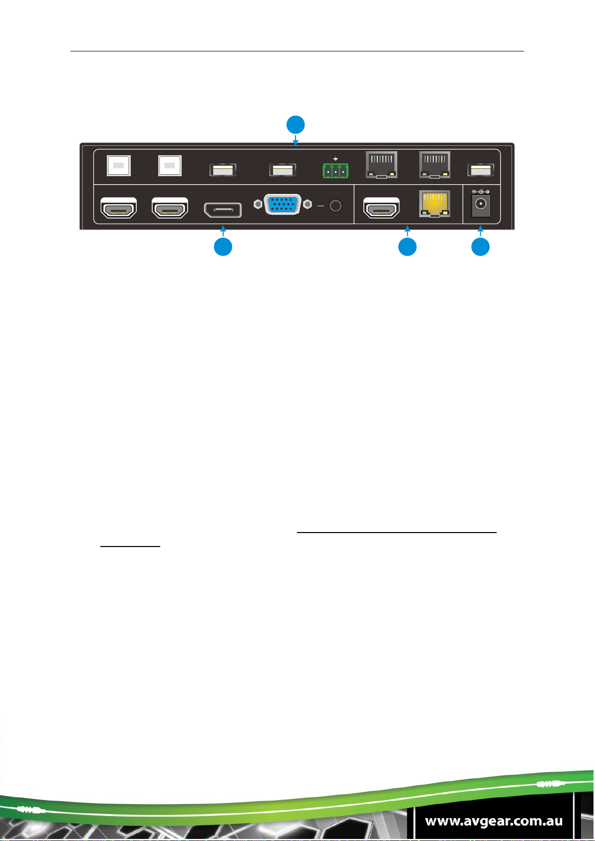
2.2. Transmitter Rear Panel
① INPUT:
VIDEO: 2 HDMI inputs, 1 DP input and 1 VGA input.
AUDIO: 1 VGA auxiliary audio input.
② OUTPUT
HDMI: HDMI video output port.
HDBT: Support 24V PoC. Connect with HDBaseT Receiver to transmit AV
signal, IR or RS232 control signal.
③ CONTROL
PC1 & PC2: Two Type-B USB ports, only one can be used to connect with a
PC at a time, and the two priority: PC1>PC2. Ideally you would have the main
PC connected to PC 1, and then PC2 is used for a laptop.
DEVICE 1 & DEVICE 2: Two Type-A USB ports, connect with USB HID
devices.
RS232: Serial port, 3-pin phoenix connector, connect with a control device
(such as PC).
TCP/IP: RJ45 connector, connect with PC to control this system via web-based
GUI.
LAN: Ethernet port for extending network signal.
Note: Please notice warning signs. The LAN port can’t be connected with
HDBT port.
FIRMWARE: Type-A USB port for updating system firmware or loading
customized EDID data.
④ DC 24V: DC barrel connector for connecting the included power adapter.
Note: Pictures shown in this manual are for reference only.
HDMI
DC 24V INPUT
1-HDMI 2-HDMI 3-DP 4-VGA
HDBT
RS232
Tx
Rx
PC 1 DEVICE 1 TCP/IP LAN
OUTPUT
FIRMWARE
CONTROL
PC 2 DEVICE 2
AUDIO
1
2
4
3
Page 9
AVG-SC41T-CODEC
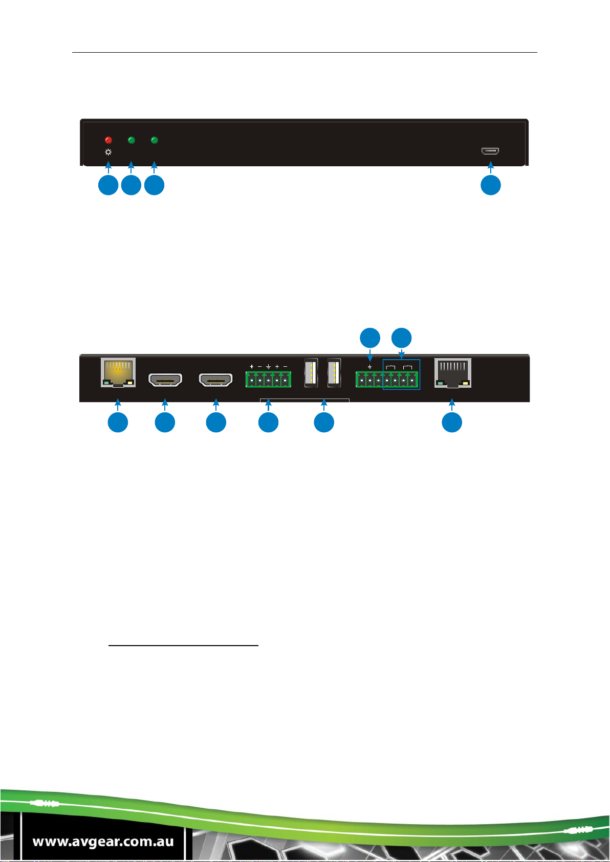
2.3. Receiver Front Panel
① POWER LED: The LED illuminates red when power is applied.
② HDBT LED: The LED illuminates green when HDBT input signal present.
③ HDMI LED: The LED illuminates green when HDMI input signal present.
④ FIRMWARE: Type-A USB port for updating system firmware.
2.4. Receiver Front Panel
① HDBT IN: Connect to the HDBT OUT port of the Transmitter via CAT5e / 6a / 7
cable. Supports PoC technology.
② HDMI IN: HDMI input port.
③ HDMI OUT: HDMI output port.
④ AUDIO OUT: Stereo balanced L/R audio output port.
⑤ DEVICES: Two Type-A USB ports, connect with USB HID devices.
⑥ RS232: Serial port, 3-pin phoenix connector, connect with the display device
(such as projector) needed to be control via RS232 commands.
⑦ RELAY1 & RELAY2: Connect with relay device (such as projector screen).
⑧ LAN: Ethernet port, works with the LAN port on the Transmitter to extend
network signal.
Note: Please notice warning label. The LAN port can’t be connected with HDBT port.
FIRMWARE
HDBT HDMI
1
2
3
4
HDBT IN
HDMI IN HDMI OUT AUDIO OUT
L R
DEVICES
1
2
Tx Rx
CONTROL
Relay1 Relay2
LAN
1
2
3
4
5
8
6
7
Page 10
AVG-SC41T-CODEC
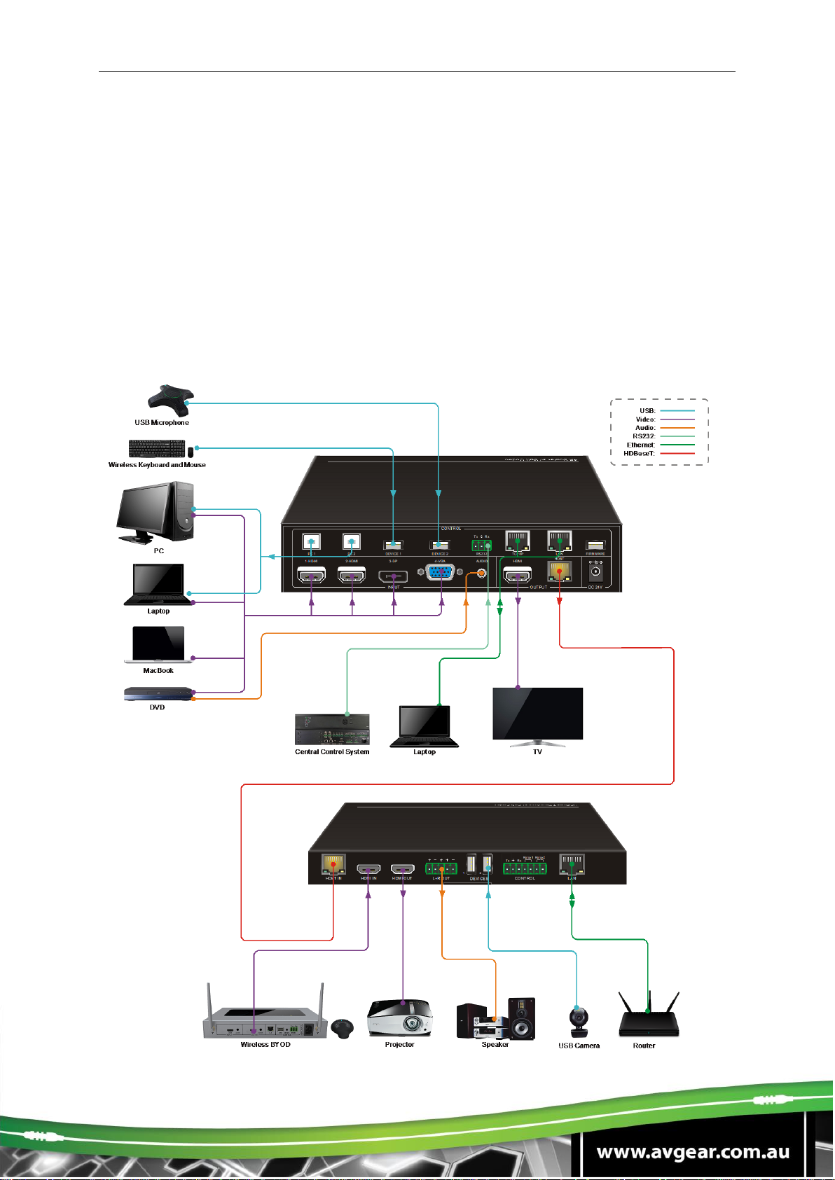
3. System Connection
3.1. Usage Precautions
1. The system should be installed in a clean environment that has proper
temperature and humidity.
2. All the power switches, plugs, sockets and power cords should be insulated and
safe.
3. All devices should be connected before powering it on.
3.2. System Diagram
Page 11
AVG-SC41T-CODEC
4. Operation
4.1. Front Panel Control
Front panel buttons can be used for switching operations, OSD and volume control.
4.1.1. Manual Switching
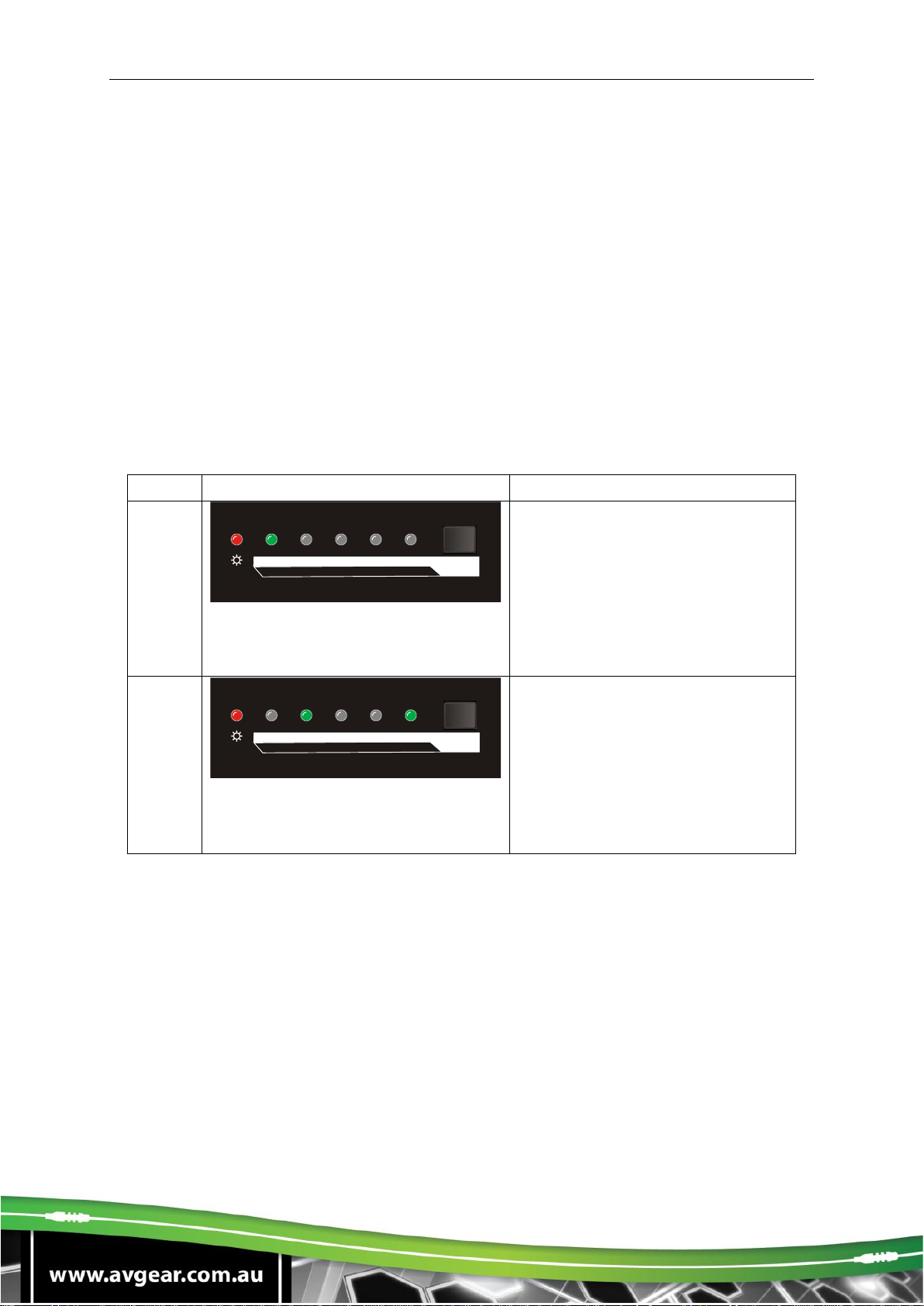
Press the SOURCE/AUTO button to select an input for the Transmitter, press again
to select next source, switching sequentially between 1-HDMI, 2-HDMI, 3-DP and 4VGA. The corresponding LED will illuminate green.
The Receiver also features one HDMI input port, if you need to output the source
signal via its HDMI output port. The following is an example.
LED Status
Description
Status
1
The 1-HDMI LED illuminates
green, other source LEDs are
gone.
The 1-HDMI is selected as input
source. The input signal will be
transmitted to all video output
ports of Transmitter and
Receiver.
Status
2
The 2-HDMI and RX HDMI LEDs
illuminate green, other source
LEDs are gone.
The 2-HDMI is selected as
input source for Transmitter.
The input signal will be
transmitted to all video
output ports of Transmitter.
The HDMI input signal on
Receiver will be only
transmitted to the HDMI
output port of Receiver.
Follow the below steps to switch to the status 2 from status 1.
① Press the SOURCE/AUTO button once to select 2-HDMI, and then release this
button.
② Press the SOURCE/AUTO button continuously until the RX HDMI LED
illuminates green to select the HDMI input for Receiver.
RX HDMI SOURCE
AUTO/3s
1-HDMI 2-HDMI 4-VGA3-DP
RX HDMI SOURCE
AUTO/3s
1-HDMI 2-HDMI 4-VGA3-DP
Page 12

AVG-SC41T-CODEC
4.1.2. Auto-Switching
Long-press the SOURCE/AUTO button for 3 seconds or more to enable autoswitching mode. The auto-switching mode works as follows:
New input
Once the Transmitter detects a new input signal and it isn’t already locked onto
an input, it will switch to this new signal automatically.
Rebooting device
The Transmitter can save the last configuration before losing power. If the last
switching mode is auto-switching, once rebooted, the Transmitter will
automatically enter auto-switching mode, then detect all inputs and memorize
their connection status for future rebooting use. If the last displayed signal is still
available, the unit will output that signal. If not, the unit will detect any other input
signals with priority from 1-HDMI to 4-VGA. When the next available signal has
been detected it will switch this to the output.
Signal removing
On removal of the current source signal, the Transmitter will detect all input
signals with priority from 1-HDMI to 4-VGA. It will switch to the next available
input.
Note:
Auto-switching function works only when connecting a new signal, removing a
signal or power cycling.
The HDMI input source on Receive cannot be selected under auto-switching
mode.
4.1.3. Volume Control
The Receiver features audio output ports for connecting speakers or an AV amplifier.
Press the VOL+ or VOL- button on Transmitter to turn up or turn down the volume.
Page 13
AVG-SC41T-CODEC
4.3. RS232 Control
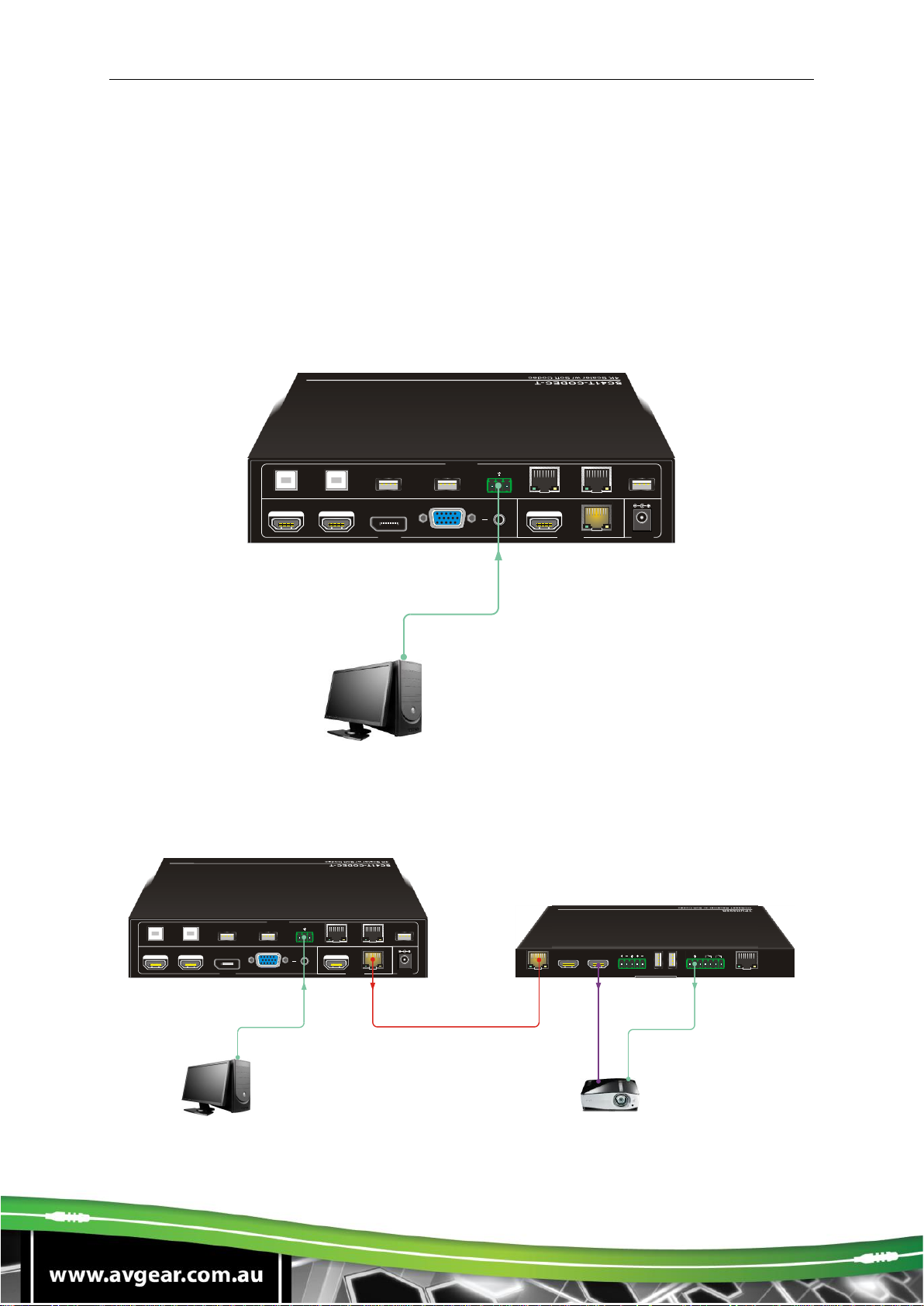
As RS232 commands can be transmitted to the Receiver from the Transmitter, so it
is able to control the Transmitter or the third-party device (such as projector) on
Receiver from local.
The baud rate support 2400, 4800, 9600(default), 19200, 38400, 57600 or 115200.
RS232 Connection
There are two RS232 control modes.
Control Transmitter
Control Display
HDMI
DC 24V INPUT
1-HDM I 2-HDMI 3- DP 4-VGA
HDBT
RS232
Tx
Rx
PC 1 DEVIC E 1 TCP/IP LAN
OUTPU T
FIRMWA RE
CONTR OL
PC 2 DEVIC E 2
AUDIO
PC
HDMI
DC 24V INPUT
1-HDMI 2-HDMI 3-DP 4-VGA
HDBT
RS232
Tx
Rx
PC 1 D EVICE 1 TCP/IP LAN
OUTPUT
FIRMWARE
CONTROL
PC 2 DEVICE 2
AUDIO
DC 12V
PC
DEVICES
Tx Rx
CONTROLHDBT IN
HDMI IN HDM I OUT L+R OUT
Relay1 Relay2
LAN
1 2
Proj ector
Page 14
AVG-SC41T-CODEC
4.3.1. Installation/Removal of RS232 Control Software
Installation: Copy the control software file to the computer connected with
the AVG-SC41T-Codec transmitter.
Uninstallation: Delete all the control software files in corresponding file path.
4.3.2. Basic Settings
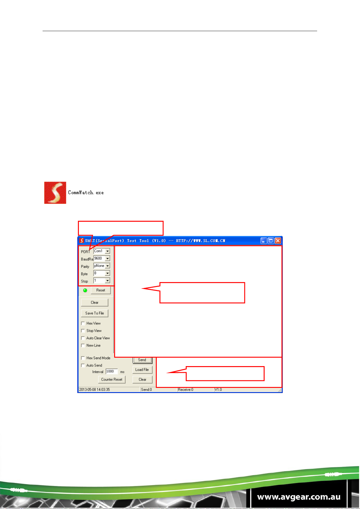
To begin with, connect the AVG-SC41T-Codec with all your input devices and output
devices required, then connect it to a PC which has some RS232 control software
installed. Double-click the software icon to run the software.
Here we have the software CommWatch.exe as an example. The icon looks like the
image below:
The interface of the control software is shown below:
Please set the parameters of COM port, baud rate, data bit, stop bit and the parity bit
correctly, and then you can successfully send commands in the Command Sending
Area.
Parameter
Monitoring area,
indicates whether the
Command Sending
Page 15
AVG-SC41T-CODEC
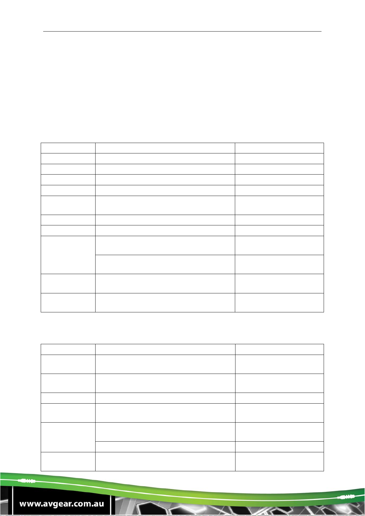
4.3.3. RS232 Control Commands
Communication protocol: RS232 control Protocol Command Type: ASCII
Baud rate: 9600 Data bit: 8 Stop bit: 1 Parity bit: none
The terminating characters for any of the commands are “<CR><LF>”. That is
carriage(h0D) return and line feed(h0A).
Source Switching
Command
Function
Feedback
SWIN H1
Switch to 1-HDMI input.
Switch to HDMI1
SWIN H2
Switch to 2-HDMI input.
Switch to HDMI2
SWIN DP
Switch to 3-DP input.
Switch to DP
SWIN VG
Switch to 4-VGA input.
Switch to VGA
SWIN
RXHDMI
Switch to RX HDMI input.
Switch to RX HDMI
AUTO 01
Enable auto-switching.
Auto Switching
AUTO 00
Enable manual-switching.
Manual Switching
?GET IN
Get the input source of Transmitter.
(HDMI1, HDMI2, DP, VGA)
TX Device Input: HDMI1
Get the input source of Receiver. (HDMI,
HDBT)
RX Device Input: HDMI
?GET AUTO
Get the switching mode.
Manual Switching/Auto
Switching
VGAA
Auto-adjust the input parameter (VGA
only).
VGA Input Auto
Audio Adjustment
Command
Function
Feedback
AUMT S1
Mute source audio.
Audio Mute Source:
Enable
AUMT S0
Unmute source audio.
Audio Mute Source:
Disable
AUMT V1
Mute VGA auxiliary input audio.
Audio Mute VGA: Enable
AUMT V0
Unmute VGA auxiliary input audio.
Audio Mute VGA:
Disable
?GET AUMT
Get the Source mute status.
Audio Mute Source:
Enable
Get the VGA auxiliary audio mute status.
Audio Mute VGA: Enable
VOLS AP
Turn up the source audio volume
(xx=00~60).
Source Volume: xx
Page 16

AVG-SC41T-CODEC
Command
Function
Feedback
VOLS AN
Turn down the source audio volume
(xx=00~60).
Source Volume: xx
VOLV AP
Turn up the VGA auxiliary audio volume
(xx=00~60).
VGA Volume: xx
VOLV AN
Turn down the VGA auxiliary audio
volume (xx=00~60).
VGA Volume: xx
VOLS xx
Set the source audio volume
(xx=00~60).
Source Volume: xx
VOLV xx
Set the VGA auxiliary audio volume
(xx=00~60).
VGA Volume: xx
?GET VOL
Get the source audio volume
(xx=00~60).
Source Volume: xx
Get the VGA auxiliary audio volume
(xx=00~60).
VGA Volume: xx
Output Resolution
The default output resolution is 3840x2160@30Hz. Below is a list of output
resolutions the built-in scaler can output.
Command
Function
Feedback
TRES 01
Set the output resolution for
Transmitter to 3840x2160@30Hz.
TX Device Resolution:
3840x2160
TRES 02
Set the output resolution for
Transmitter to 1920X1080.
TX Device Resolution:
1920x1080
TRES 03
Set the output resolution for
Transmitter to 1280x720.
TX Device Resolution:
1280x720
RRES 01
Set the output resolution for Receiver
to 3840x2160@30Hz.
RX Device Resolution:
3840x2160
RRES 02
Set the output resolution for Receiver
to 1920x1080.
RX Device Resolution:
1920x1080
RRES 03
Set the output resolution for Receiver
to 1280x720.
RX Device Resolution:
1280x720
?GET RES
Get the output resolution for
Transmitter.
Tx Device Resolution:
1920x1080
Get the output resolution for Receiver.
Tx Device Resolution:
1920x1080
Page 17

AVG-SC41T-CODEC
Auto Power Off Setup
Command
Function
Feedback
?GET TIME
Check the auto power-off mode.
Auto Switch Mode no
input to shut down time:
Disable
Manual Switch Mode no
input to shut down time:
Disable
TIME AD
Auto Switch Mode: Disable the auto
power-off function.
Auto Switch Mode no
input to shut down time:
Disable
TIME A1
Auto Switch Mode: Set the auto poweroff time to 1 minute when No signal
input.
Auto Switch Mode no
input to shut down time:
1 minutes
TIME A2
Auto Switch Mode: Set the auto poweroff time to 2 minutes when No signal
input.
Auto Switch Mode no
input to shut down time:
2 minutes
TIME A3
Auto Switch Mode: Set the auto poweroff time to 5 minutes when No signal
input.
Auto Switch Mode no
input to shut down time:
5 minutes
TIME A4
Auto Switch Mode: Set the auto poweroff time to 10 minutes when No signal
input.
Auto Switch Mode no
input to shut down time:
10 minutes
TIME MD
Manual Switch Mode: Disable auto
power-off time function.
Manual Switch Mode no
input to shut down time:
Disable
TIME M1
Manual Switch Mode: Set the power-off
time to 1 minute.
Manual Switch Mode no
input to shut down time:
1 minutes
TIME M2
Manual Switch Mode: Set the power-off
time to 2 minutes.
Manual Switch Mode no
input to shut down time:
2 minutes
TIME M3
Manual Switch Mode: Set the power-off
time to 5 minutes.
Manual Switch Mode no
input to shut down time:
5 minutes
TIME M4
Manual Switch Mode: Set the power-off
time to 10 minutes.
Manual Switch Mode no
input to shut down time:
10 minutes
Page 18
AVG-SC41T-CODEC
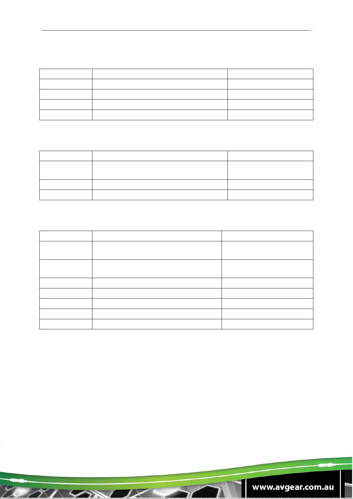
Relay Control
Command
Function
Feedback
RLY1 ON
Turn on the Relay 1.
Relay 1 on
RLY1 OFF
Turn off the Relay 1.
Relay 1 off
RLY2 ON
Turn on the Relay 2.
Relay 2 on
RLY2 OFF
Turn off the Relay 2.
Relay 2 off
EDID Configuration
Command
Function
Feedback
EDID DF
The source device obtains the default
EDID 3840x2160@30Hz.
EDID: Initial
EDID US
Load customize EDID data from U-disk.
EDID: User
?GET EDID
Get EDID status.
EDID: Initial/ User
Device Setup
Command
Function
Feedback
SFUD TX
Update the software of Transmitter.
TX Device Software
Update
SFUD RX
Update the software of Receiver.
RX Device Software
Update
?GET REV
Get the system version.
Vx.x.x
FRST
Restore to factory defaults.
Factor Reset
WAKE
Wake up the system.
Wake Up
STBY
Let this system enter in standby mode.
Go To Standby
?GET IP
Get the IP address.
192.168.0.178!
Page 19
AVG-SC41T-CODEC
4.4. OSD Menu Control
The AVG-SC41T-CODEC features a powerful OSD menu, including picture settings
and system setup.
Operation:
Press the button MENU/ENTER to enter OSD menu.
Press direction buttons (Left/Right/Up/ down) to select function on OSD menu.
Press MENU/ENTER button to confirm the selected function.
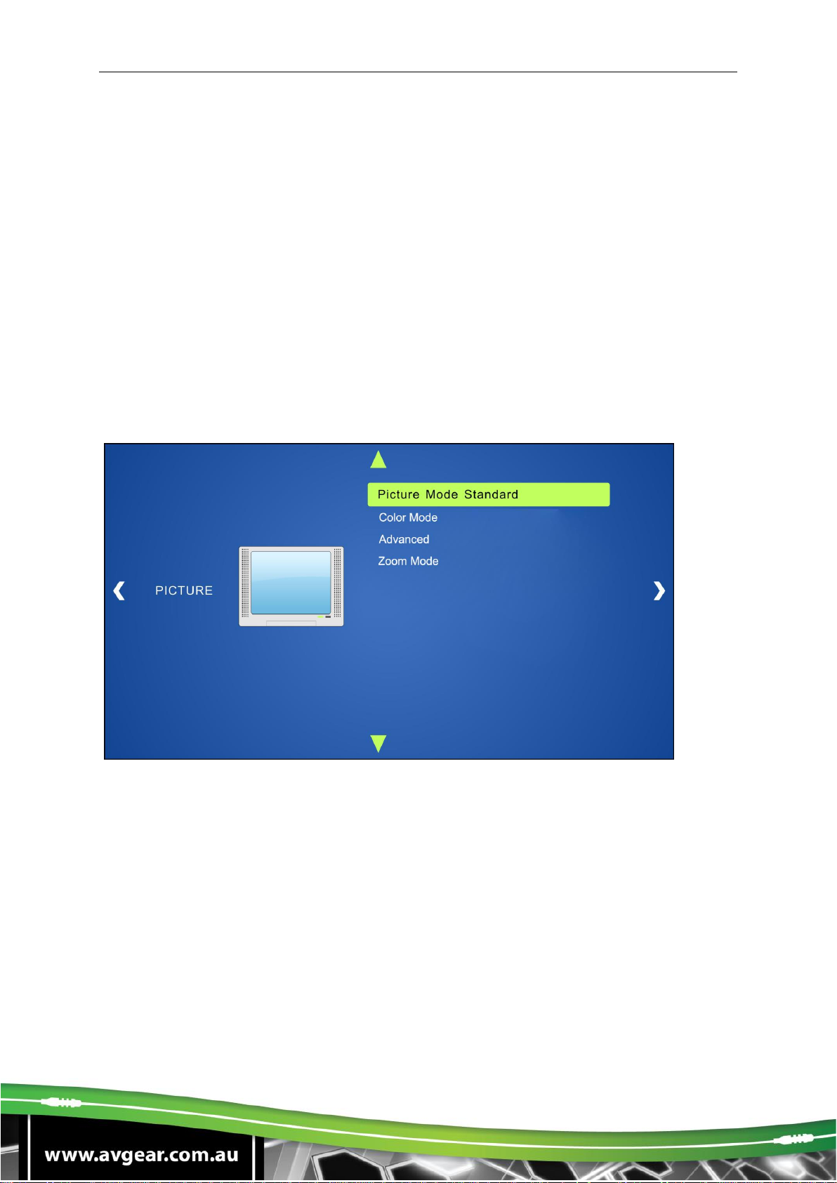
4.4.1. Picture Menu Item
Including Picture Mode, Color Mode, Advanced and Zoom Mode.
Picture mode: Including Dynamic, Standard, Soft, and Personal. Only in
Personal mode, will it be able to set the image contrast, brightness, color and
sharpness.
Color Mode: Including Normal, Cool, Medium.
Advanced: Including H-Pos, V-Pos, Clock, Phase, and Auto.
Zoom Mode: Including Normal, Zoom, Cinema, Wide.
Page 20
AVG-SC41T-CODEC
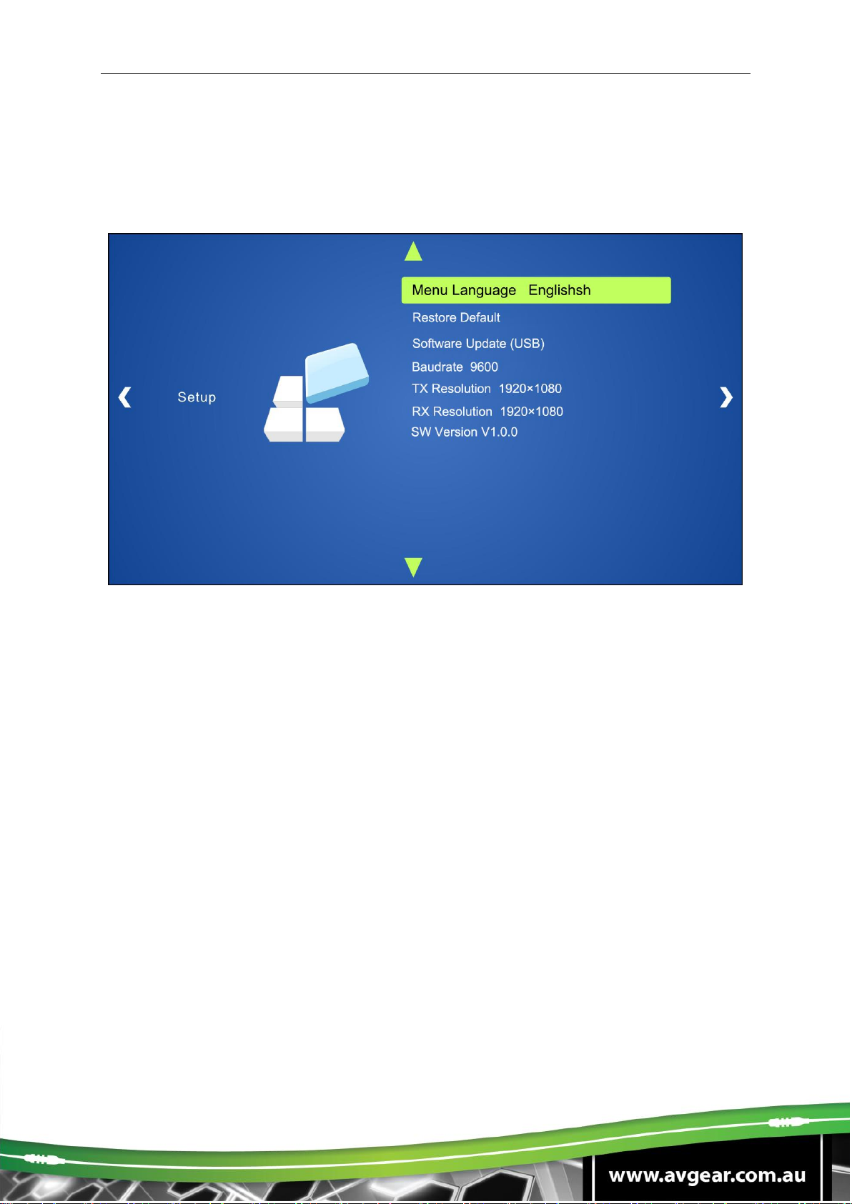
4.4.2. Setup Menu Items
Including Menu Language, Restore Default, Software Update, Baudrate, TX
Resolution, RX Resolution and SW Version.
Menu Language: Supports 3 languages, including English (default), French, and
Spanish.
Restore Default: Restores to original system state.
Software Update (USB): Insert the USB flash disk with updating file to the
FIRMWARE port of the Scaler Switcher, to update the software through this
menu.
Baudrate: Set the baud rate for RS232 control, and it support 2400、4800、9600
、19200、38400、57600、115200.
TX Resolution: Set the output resolutions for Transmitter, and it support
3840x2160@30Hz, 1920x1080, 1280x720.
TX Resolution: Set the output resolutions for Receiver, and it support
3840x2160@30Hz, 1920x1080, 1280x720.
SW Version: Software version.
Page 21
AVG-SC41T-CODEC
4.5. Web-based GUI Control
The AVG-SC41T-CODEC can also be controlled via a web-based GUI. Users can
interact with the Scaler Switcher through graphical icons and visual indicators in any
web browser window.
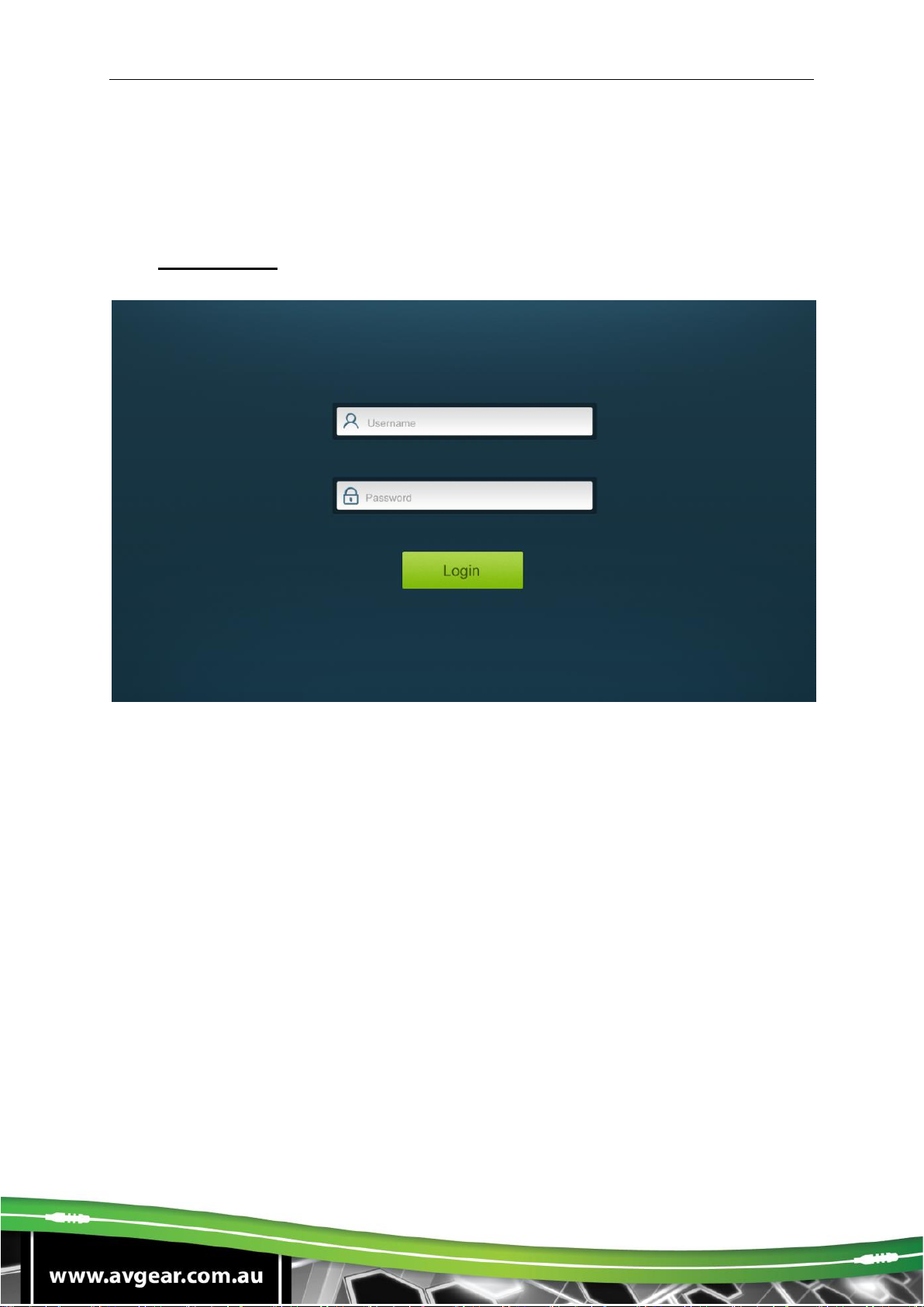
Type 192.168.0.178 in your browser, it will enter the log-in interface shown as below:
This system only has a user mode.
User mode: User name: user; Password: user (default setting)
Page 22
AVG-SC41T-CODEC
4.5.1 Control Menu
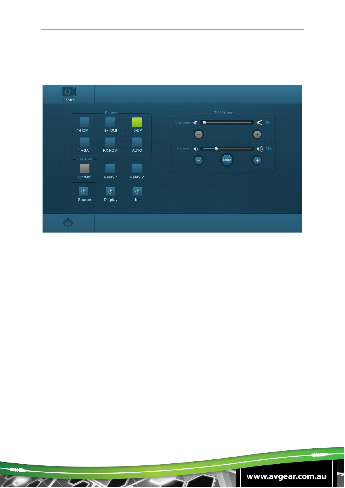
Type user name: user and password: user (default) and then click Login to enter
Control menu shown below:
Sources:
Click the corresponding button (1-HDMI, 2-HDMI, 3-DP, 4-VGA and RX HDMI)
to select video input source.
Click AUTO button to enter auto-switching mode.
VGA Audio: Click this button to turn on/off the VGA auxiliary audio input.
Relay1: Click this button to roll up the projector screen.
Relay2: Click this button to drop the projector screen down.
Source: Click this button to turn on/off source device.
Display: Click this button to turn on/off output display device.
Unit: Click this button to make the Transmitter and Receiver to enter standby
mode.
TX Volume: Click +/- button or drag the volume bar to adjust volume.
Page 23
AVG-SC41T-CODEC
4.5.2. Configuration Menu
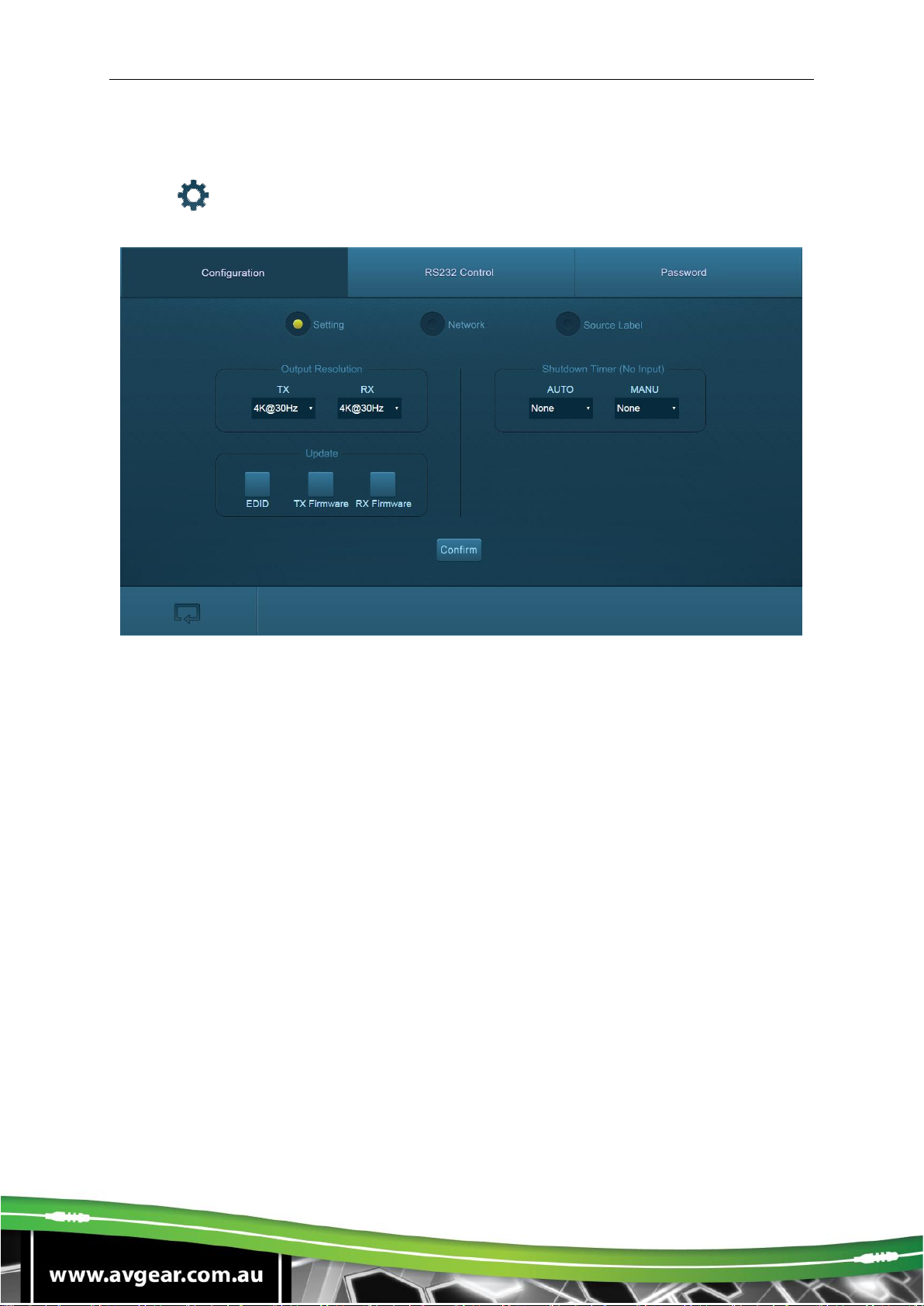
1. Click icon in control menu to enter the configuration Menu shown as below:
Output Resolution: Select the output resolution for Transmitter or Receiver.
Update:
EDID: Insert the USB flash disk with EDID file to the FIRMWARE port of
Transmitter, and then click EDID button to start update procedure.
TX Firmware: Insert the USB flash disk with software updating file to the
FIRMWARE port of Transmitter, and then click TX Firmware button to start
update procedure.
RX Firmware: Insert the USB flash disk with software updating file to the
FIRMWARE port of Receiver, and then click RX Firmware button to start
update procedure.
Shutdown Time (NO Input): Set the auto power-off time or manual power-off
time, including none, 1 minute, 2minutes, 5minutes and 10 Minutes. If the system
can’t detect video source input, it will automatically shut down after a preset
interval.
Page 24
AVG-SC41T-CODEC
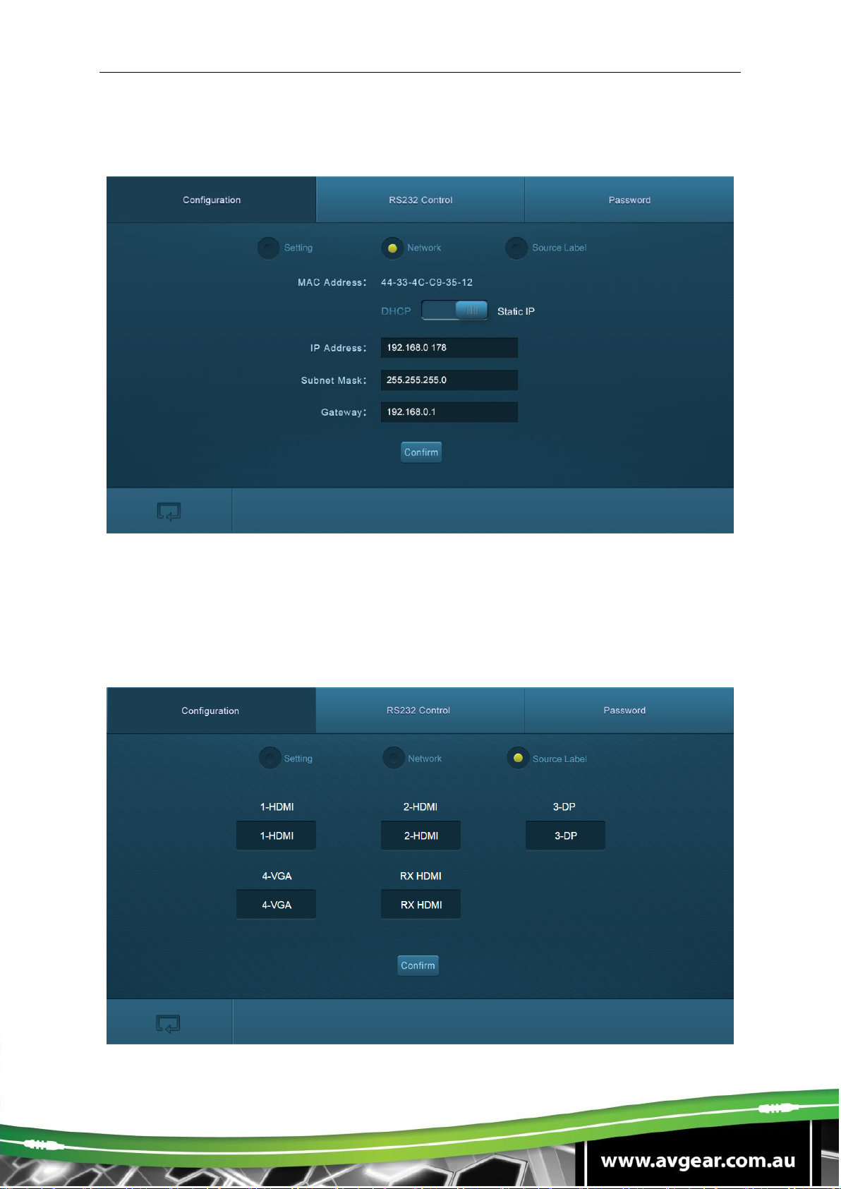
2. Click the Network button to enter the network setting menu shown as below:
In this interface, dynamic or static IP mode can be selected. Under static IP mode, IP
address and subnet mask, gateway can be set. Be sure the IP addresses are
different from others on your network to avoid an IP conflict.
3. Click Source Label to enter source label setting menu shown as below:
Page 25
AVG-SC41T-CODEC
In this interface, you can edit the names of the source inputs to suit your needs.
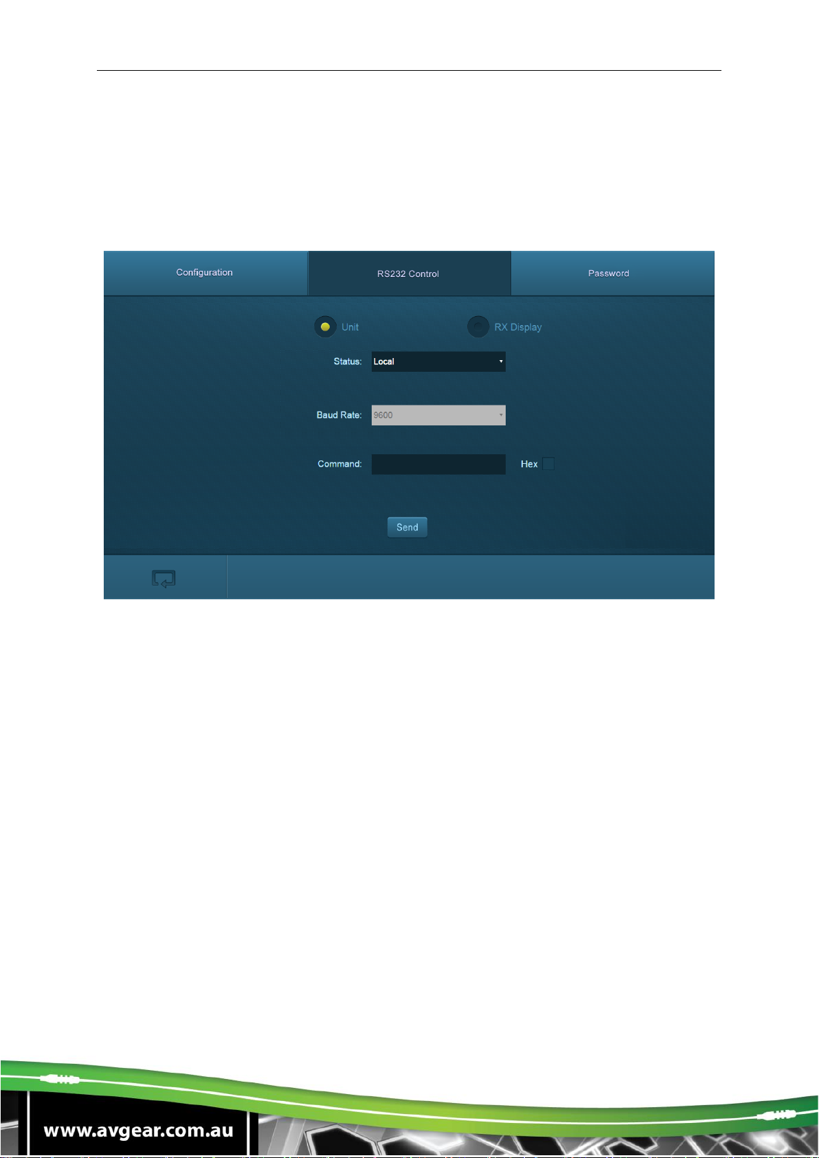
4.5.3 RS232 Control Menu
Click the RS232 Control tab on the top of interface to enter the RS232 control menu
shown below:
Status:
Local: Refers to the RS232 port of the Transmitter.
HDBT: Refers to the RS232 port of the Receiver.
Baud Rate: The baud rate of local port is 9600, but for HDBT port, it supports
2400、4800、9600、19200、38400、57600、115200.
Command: Typing commands in this box to control the third-party device (such
as integrated control system) connected to Transmitter, or the far-end third-party
device (such as projector) connected to Receiver. If check the “Hex”, you can
type RS232 commands with hexadecimal value in the box.
Page 26
AVG-SC41T-CODEC
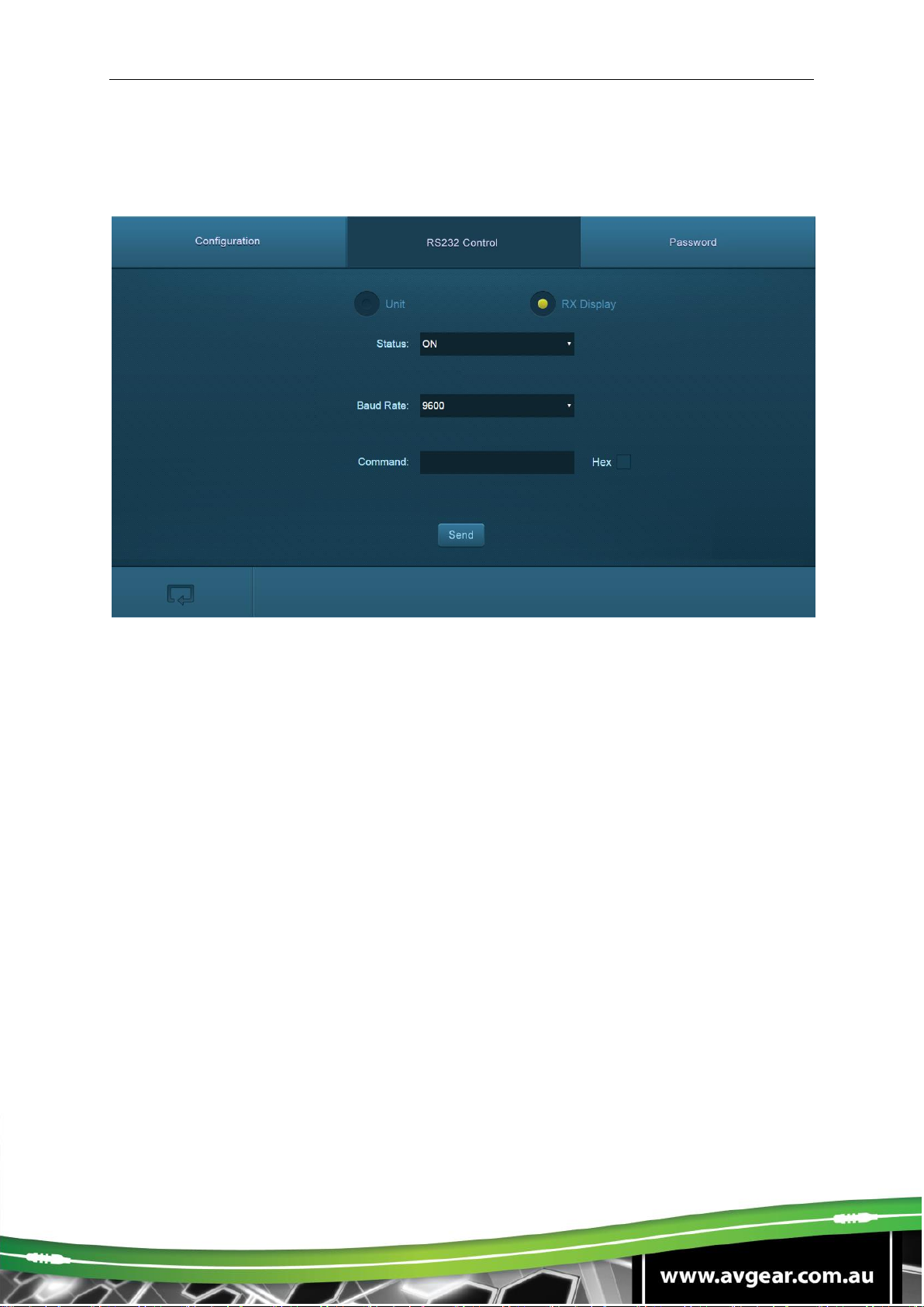
Click RX DISPLAY to enter the below menu to set the ON/OFF button function to
turn on/ off the display device (such as projector).
Status: ON or OFF can be chosen.
Baud Rate: Supports 2400、4800、9600、19200、38400、57600、115200.
Command: Typing the control command of display device, and then click Send,
the command will be sent to DISPLAY ON/OFF button.
Page 27
AVG-SC41T-CODEC
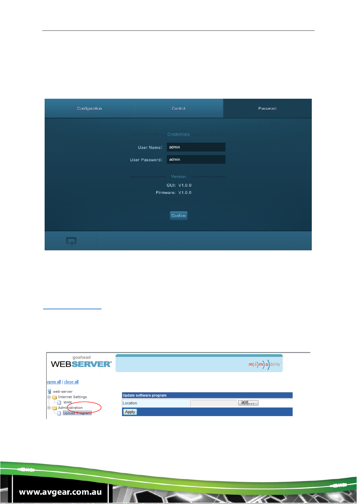
4.5.4 Password Menu
Click the Password tab on the top of interface to enter the password menu shown
below:
In this interface, the user name and password can be modified as required.
4.5.5 Web-based GUI update
Web-based GUI for the Scaler Switcher features an online update available at
http://192.168.0.178:100. Note, if you have changed the IP address of the AVG-SC41T-
CODEC, then enter that IP address. Type the username and password (the same as
in the GUI log-in settings, a modified password will be available only after rebooting)
to log in the configuration interface. After that, click Administration at the source
menu to get to the Upload Program option as shown below:
Select the required update file and press Apply, it will then start updating.
Page 28
AVG-SC41T-CODEC
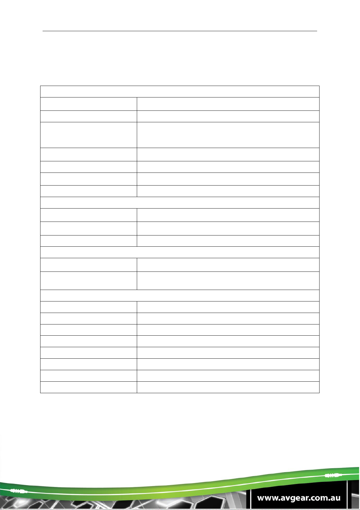
5. Specification
Transmitter
Video
Video Input
(2) HDMI; (1) DP; (1) VGA
Video Input Connector
(2) Female HDMI; (1) DisplayPort; (1) Female VGA (15-pin)
Input Resolution
HDMI: Up to 4Kx2K@30Hz 4:4:4
DP: Up to 4Kx2K@30Hz 4:4:4
VGA: Up to 1920x1200@50/60Hz
Video Output
(1) HDMI; (1) HDBaseT
Video Output Connector
(1) Female HDMI; (1) RJ45
Output Resolution
Supports 3840x2160@30Hz, 1920x1080, 1280x720
Standards
Compliant with HDMI 1.4 & HDCP2.2
Audio
Audio Input
(1) AUDIO
Audio Input Connector
(1) 3.5mm Stereo jack
Audio Input Impedance
>10kΩ
Control Part
Control port
(2) PC, (2) DEVICE; (1) RS232; (1) TCP/IP; (1) LAN
Control Connector
(2) Type-B USB; (2) Type-A USB; (1)3-pin phoenix
connector; (2) RJ45
General
Transmission Distance
Up to 100m
Operation Temperature
0 ~ +40℃
Storage Temperature
-10 ~ +55℃
Relative Humidity
10% ~ 90%
External Power Supply
Input: AC 100~240V, 50/60Hz; Output: 24VDC 2.71A
System Power Consumption
40w (Max)
Dimension (W*H*D)
220mm x 44mm x 120mm
Net Weight
617g
Page 29

AVG-SC41T-CODEC
Receiver
Video
Video Input
(1) HDBT; (1) HDMI
Video Input Connector
(1) RJ45; (1) Female HDMI
Input Resolution
HDBT: Up to 4Kx2K@30Hz 4:4:4
HDMI: Up to 4Kx2K@30Hz 4:4:4
Video Output
(1) HDMI
Video Output Connector
(1) Female HDMI
Output Resolution
Supports 3840x2160@30Hz, 1920x1080, 1280x720
Standards
Compliant with HDMI 1.4 & HDCP2.2
Audio
Audio Output
(1) Stereo balanced L/R audio
Audio Output Connector
(1) 5-pin phoenix connector
Audio Output Impedance
70Ω
Frequency Response
20Hz~20K Hz
Stereo Channel Separation
>80dB @1KHz
Control Part
Control port
(2) DEVICE; (1) RS232; (2) RELAY; (1) LAN
Control Connector
(2) Type-A USB; (1) 3-pin phoenix connector;
(2) 2-pin phoenix connector; (1) RJ45
General
Transmission Distance
Up to100m
Operation Temperature
0 ~ +40℃
Storage Temperature
-10 ~ +55℃
Relative Humidity
10% ~ 90%
External Power Supply
Powered by Transmitter
System Power Consumption
40w (Max)
Dimension (W*H*D)
205mm x 21.5mm x 95mm
Net Weight
358g
Page 30
AVG-SC41T-CODEC
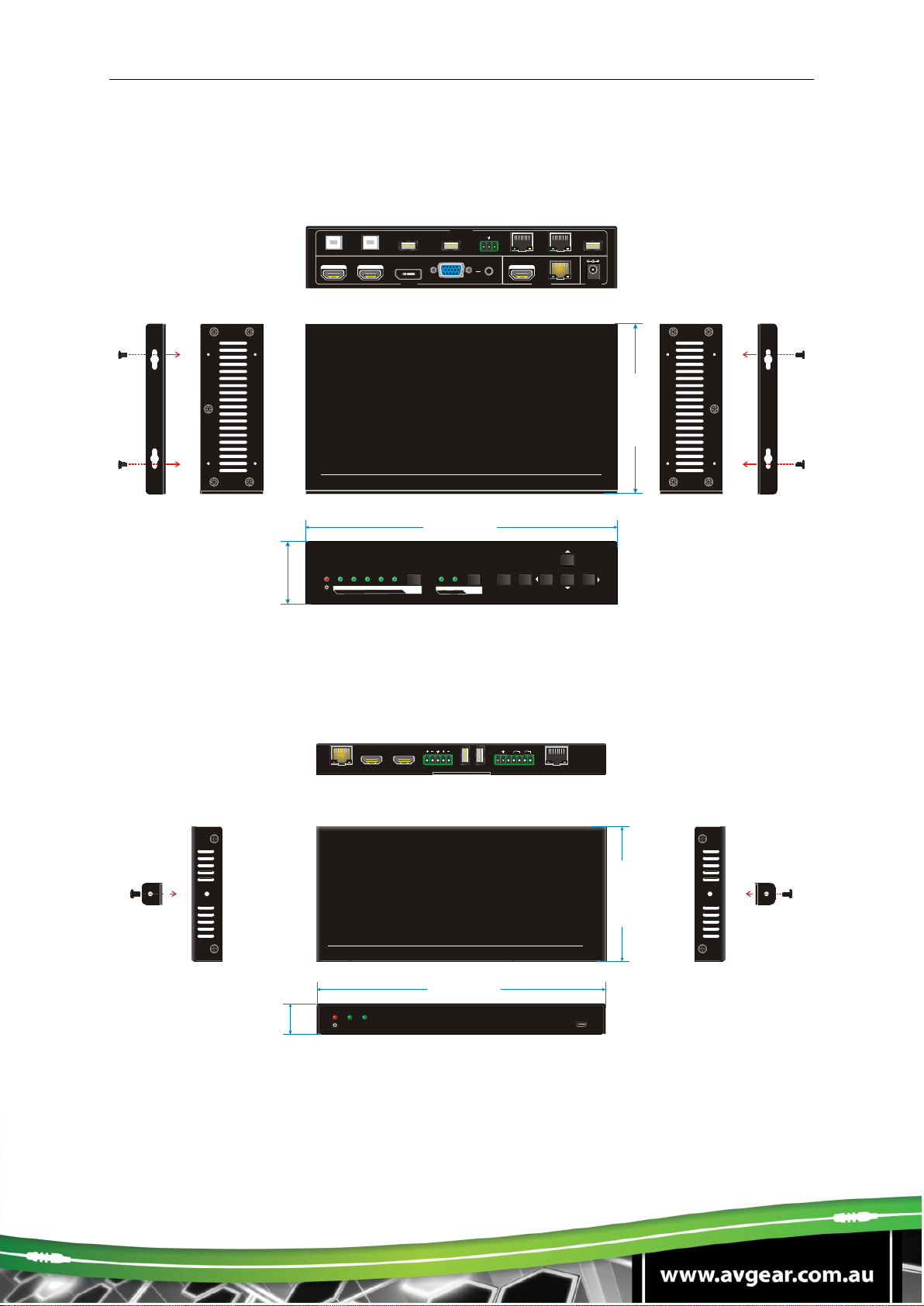
6. Panel Drawing
Transmitter
Receiver
HDMI
DC 24V INPUT
1-HDMI 2 -HDMI 3 -DP 4-VGA
HDBT
RS232
Tx
Rx
PC 1 DEVICE 1 TCP/IP LAN
OUTPUT
FIRMWARE
CONTROL
PC 2 DEVICE 2
AUDIO
4K Scaler w/ Soft Codec
RX HDMI SOURCE
AUTO/3s
1-HDMI 2-HD MI 4-VGA3-DP
OFF D ISPLAYON
MENU
ENTER
RETURN
RELAY 1
VOL +
VOL -
MUTE/3s
RELAY 2
220.0 mm
44.0 mm
120.0 mm
HDBa seT Recei ver w/ Soft Codec
FIRMWAR E
HDBT H DMI
HDBT IN
HDMI IN HDMI OUT AUDIO OUT
L R
DEVICE S
1
2
Tx Rx
CONTRO L
Relay1 Relay2
LAN
205.0 mm
21.5 mm
95.0 mm
Page 31

AVG-SC41T-CODEC
7. Troubleshooting & Maintenance
Problems
Causes
Solutions
Output image is white
noise
Poor quality HDMI
cable or faulty cable.
Change the HDMI cable to a good quality
cable.
Failed or loose
connection
Fix the connection
No output image
when switching
No signal at the input /
output end
Check with oscilloscope or multimeter if
there is any signal at the input / output
end.
Failed or loose
connection
Fix the connection
The scaler switcher is
broken
Send it to authorized dealer for repairing.
POWER indicator
doesn’t work.
No response to any
operations
Failed power cord
connection.
Fix the connection.
EDID management
does not work
normally
The HDMI cable is
broken at the output
end.
Change for a new good quality HDMI
cable.
Static becomes
stronger when
connecting the video
connectors
Poor grounding
Check the grounding and make sure it is
connected properly.
Cannot control the
device by control
device (e.g. a PC)
through RS232 port
Wrong RS232
communication
parameters
Type in correct RS232 communication
parameters.
Broken RS232 port
Send it to authorized dealer for checking.
Cannot control the
device by front panel
buttons while can
control it through
RS232 port
The front panel buttons
are locked
Send command 50605% to unlock the
front panel buttons.
Cannot control the
device by RS232 / IR
remote / front panel
buttons
The device is faulty.
Send it to authorized dealer for repairing.
If your problem persists after following the above troubleshooting steps, seek further
help from an authorized dealer or our technical support.
 Loading...