

Page 1
FULLWHITE
MANUAL
Page 2

GENERAL
QUALITY AND SAFETY:
This projection screen is in accordance with the safety regulations in DIN standard 19045. The
screen fabric is comply with DIN 4102 part 1 and the specications of the according data sheet.
WARRANTY:
The warranty period for production deciencies is 5 years for the frame elements and 24 months
for the projection surface. The projection screen is developed for indoor use only. Any damage and
consequential damage caused by outdoor use is not covered by warranty.
FRAME ELEMENTS:
The frame elements, accessories and additional elements are maintenance-free!
PROJECTION SURFACE:
The projection surface is packed into a separate soft bag to avoid any damage by the frame parts,
bleaching and discoloration. Additionally following handling instructions have to be adhered to:
! Do not bring printed and coloring objects (instructions, magazines, etc.) in contact with the
projection surface
! Do not mark the projection surface!
Colors penetrate the projection surface and cannot be cleaned anymore!
Store the projection surface cleaned and dry at room temperature only!
When transporting the projection surface at low temperatures, do not mount the surface unless
it has reached its full elasticity at room temperature. Otherwise there is the risk of cold break of the
projection screen.
FOLDED STORAGE
The projection surface has to be folded with the front layer inside and we recommend to lay out the
enclosed foamed plastic foil between the surface layers to avoid permanent marks, soil and
damage.
ROLLED STORAGE
Packing the projection surface we recommend to lay out the enclosed foamed plastic foil between the
surface layers to avoid permanent marks.
CLEANING OF THE PROJECTION SURFACE:
Use a white clean cotton cloth saturated with clear water (optionally mild soap water) and gently
wipe the area in one direction (no circular motion). Wipe dry with another cotton cloth.
To clean a stubborn stain, use methylated spirit and follow the same procedure.
Clean rear projection surfaces in case of imperative only!
Subject to modications, errors expected !
Page 3
OVERVIEW
Further development of the mobile projection screens for applications where technology plays a secondary role and puristic design is required.
With the minimalistic design this projection screen ts easily in every optical superior installation.
Universal, invisible mounting options as well as high stability and exibility are essential features of this
projection system.
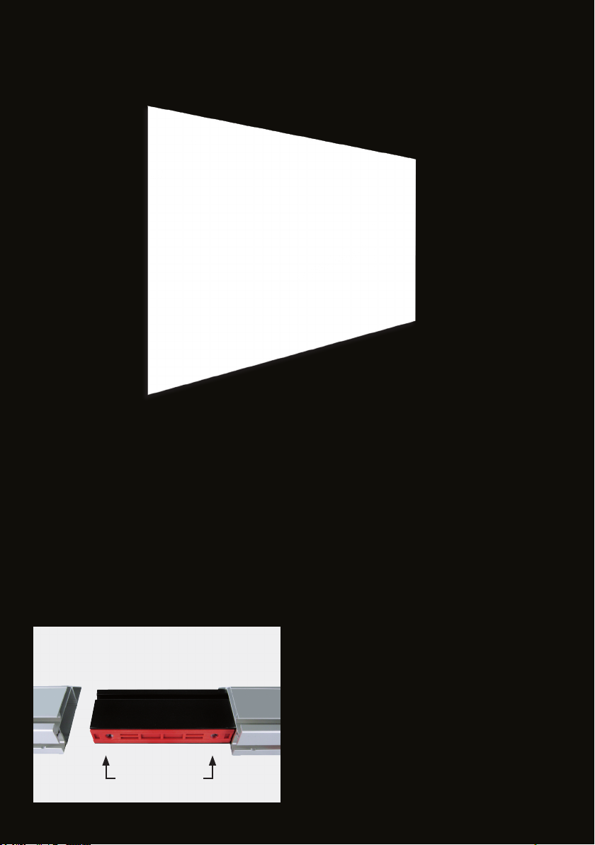
SYSTEM COMPONENTS:
The hollow chamber prole with trapezoid shape
gives an extra high stability and allows a perfect
clamp connector with
clamping prole (red)
clamp screwsframe prole
frame prole
wrinkle-free application of the projection surface
on the backside of the prole with hooks or Velcro.
The clamp connectors with the patented shape of
the clamping prole (red) guarantees a secured
and solid connection, like a monolithic system.
The corner parts are designed as a single piece
construction with a minimum tolerance, thereby
ensuring the highest precision.
Page 4
FRAME SET UP
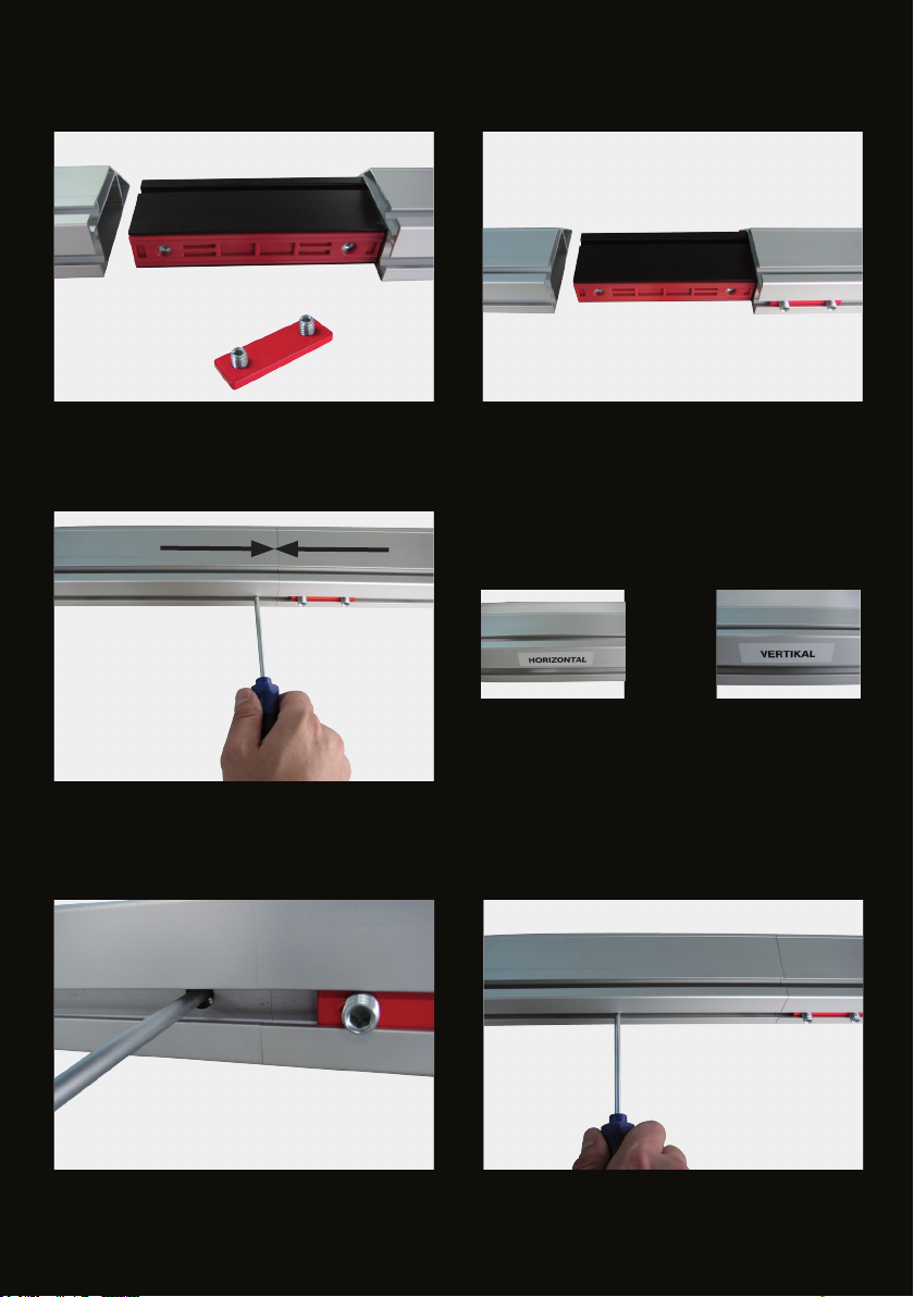
In case a positive connection is required, each
clamp connection can be secured with the
enclosed red locking plate.
Stick together each straight frame prole with
a clamp connector with the subsequent frame
section according to the labels.
Insert the red locking plate into the inner slot,
according to the picture on the left.
or
The connection is secured with a screwdriver by turning the two clamp screws clockwise.
Page 5
CONNECTION PLATE
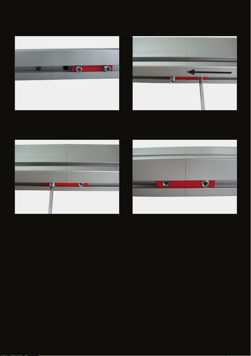
Slide the connection plate (red) over the securing holes as shown on pictures and tighten the locking pins
with the enclosed screwdriver completely.
Page 6
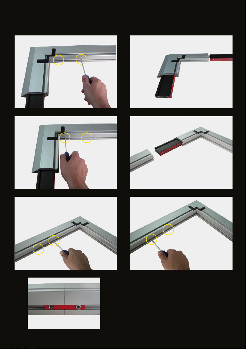
FRAME SET UP
Put together the connected upper and lower
straight horizontal frame elements with corner
parts on each end. Clamp the connection by
turning the two clamp screws clockwise and
secure the connections with the red locking
plates.Next plug in the vertical elements, clamp
and secure them in the same way.The vertical
7
connections must always be secured with the
locking plates!
Page 7
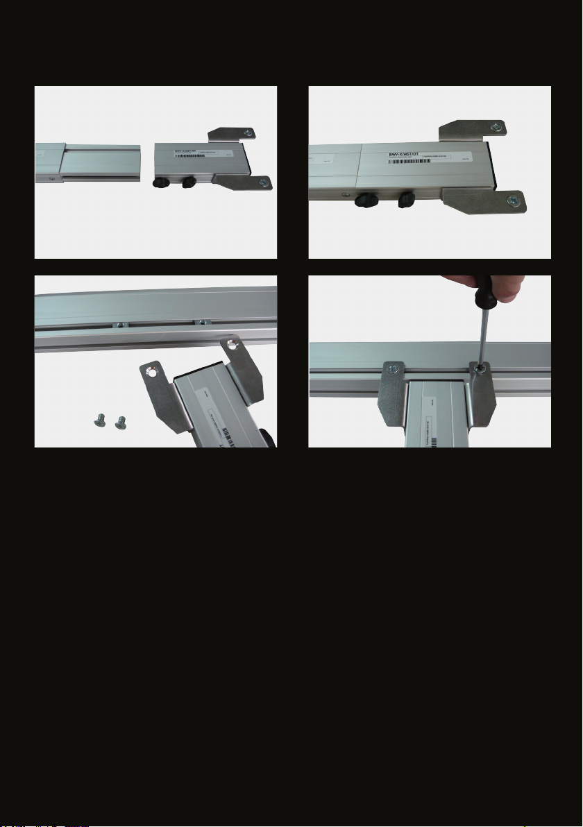
CENTER SUPPORT
1
2
3 4
1-2 Put together the center support according to the labels and secure the connections with the two
wing nuts.
3 Detach the pivot nuts from the top and bottom center support element and insert them into the
inner slot of the horizontal frame bar.
4 Place the center support and secure it on top and bottom with the Phillips screws.
Page 8
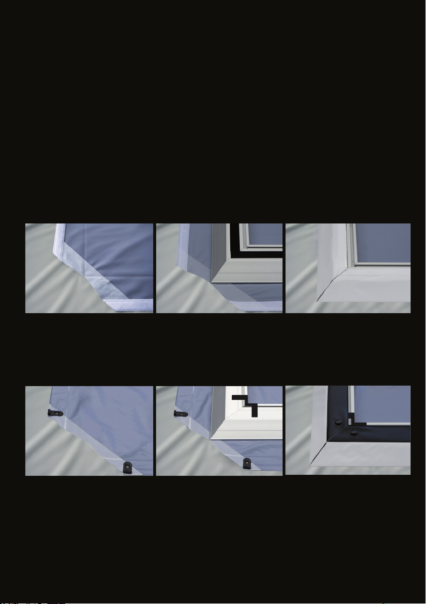
PROTECTIVE FOIL
ATTENTION!!
Before you unroll the projection surface with the projection side down, the oor has to be cleaned
completely and the supplied protective foil has to be laid out.
The protective foil is to prevent contamination and damage to the projection side of the projection
surface.
SURFACE MOUNTING
The frame now needs to be placed at onto the backside of the projection surface according to the
photo.This step has to be carried out with several people to avoid any damage of the projection
surface!
PROJECTION SURFACE WITH VELCRO
Fold the surface to the backside of the frame and thighten it with the Velcro.
3
PROJECTION SURFACE WITH HOOKS
Fold the surface to the backside of the frame, thighten it and x it with the hooks in the slot
The projection surface is kept in position by the special corner clips.
Page 9
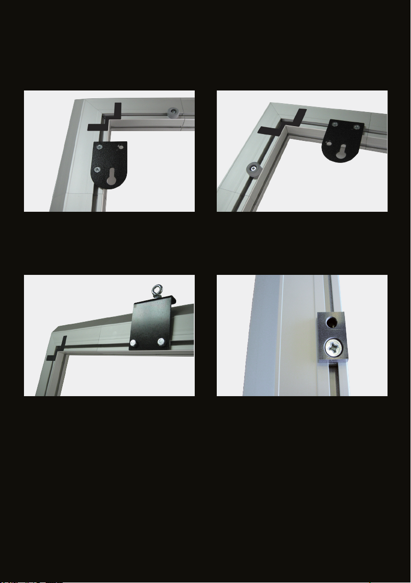
MOUNTING OPTIONS
MOUNTING BRACKET FOR WALL MOUNTING
Optional as vertical or horizontal mounting point
Vertikal mounting Horizontal mounting
MOUNTING BRACKET FOR CEILING
SUSPENSION
MOUNTING POINT FOR LEGS:
Individually movable mounting points with M8
threaded inserts for legs can be mounted at
the back of the frame prole.
Page 10
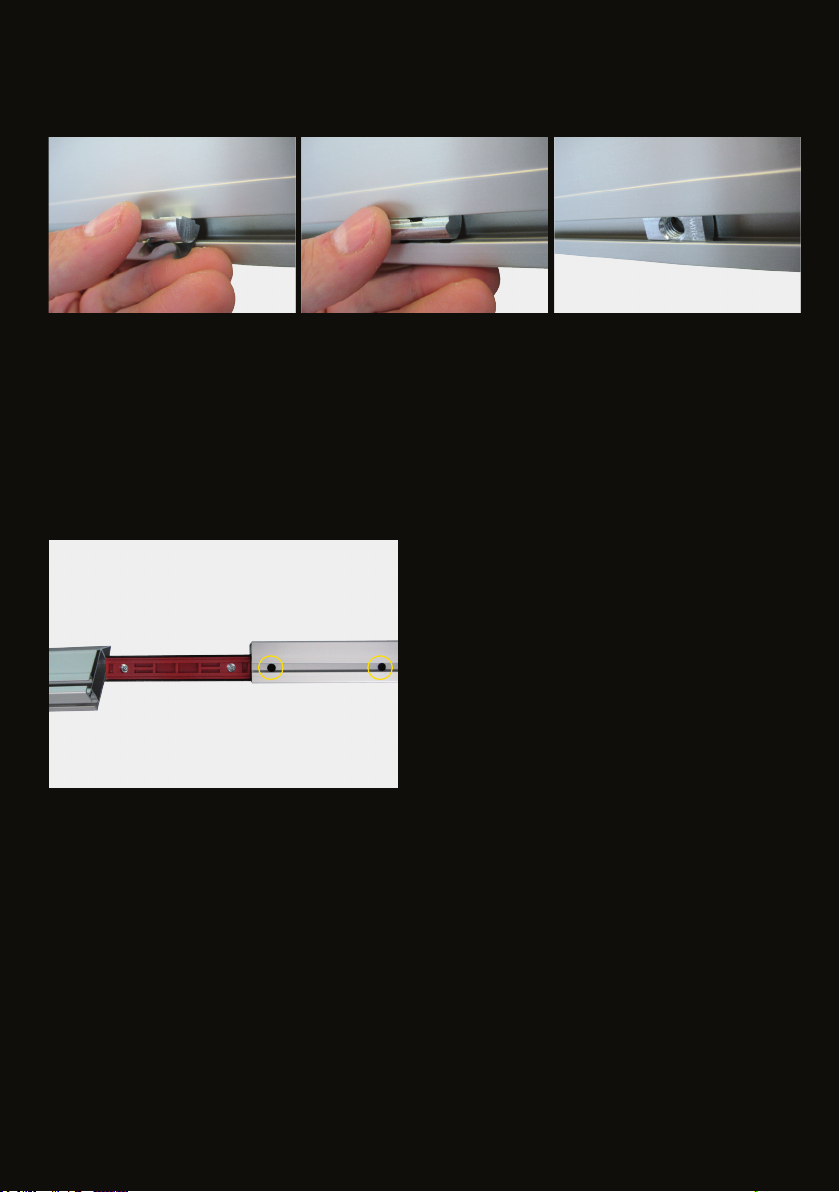
PIVOT NUTS
General attachment of pivot Nuts M8
DISASSEMBLY
The dismantling is done in reverse order.
The black colored clamp points should stay con-
nected with the frame prole (see photo).
2 31
Page 11
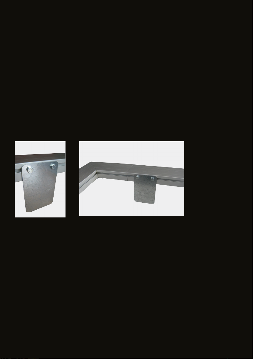
ACCESSORIES
MOUNTING PLATE
The installation of the projection surface with large FULLWHITE is done by using mounting plates.These mounting plates
lifts the frame and it oats above the ground about 11cm (4.5 inches).
Through the gained ground clearance the projection surface can be strached around the frame and hooked into the
underlying groove easily.
Using this mounting plates it is no longer neccessary to lay out the surface on the oor.
These mounting plates are attached to the two pivot nuts M8 in the inner groove and required for the period of assem-
bly only. The mounting plates shall be allocated next to the four corners and the remaining plates should be mounted
regularely on the horizontal and vertical bars .
After the attachement of the projection surface the mounting plates can be removed.
Page 12

 Loading...