

Page 1
VF
I
Instructions Update/Addendum
1
www.video-furn.com
288 Don Hillock Drive |Aurora |Ontario|L4G 0G9 | 1.877.834.3876
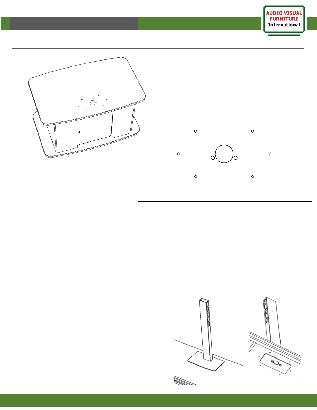
Note: PM2 mounts hole pattern.
Note:
If your cart or credenza has precut holes to support
this PM2-mount:
You may have both old and new hole patterns precut
into your furniture as we transition from first to
second generation.
These are designed to work with either generation
mounts and will not affect the strength or appearance
of the mount or furniture.
Page 2
VF
I
Assembly Instructions
PM2-S/D/XL/CS Mounts
Thank you for purchasing AVFI’s PM2-series mount.
This product is designed for mounting to a table, cart or credenza at approx. 30” height.
Read these instructions start to finish before beginning installation.
Note: If you cannot understand these instructions or are concerned about safety of the installation contact a qualified
contractor or contact AVFI at 1-877-834-3876
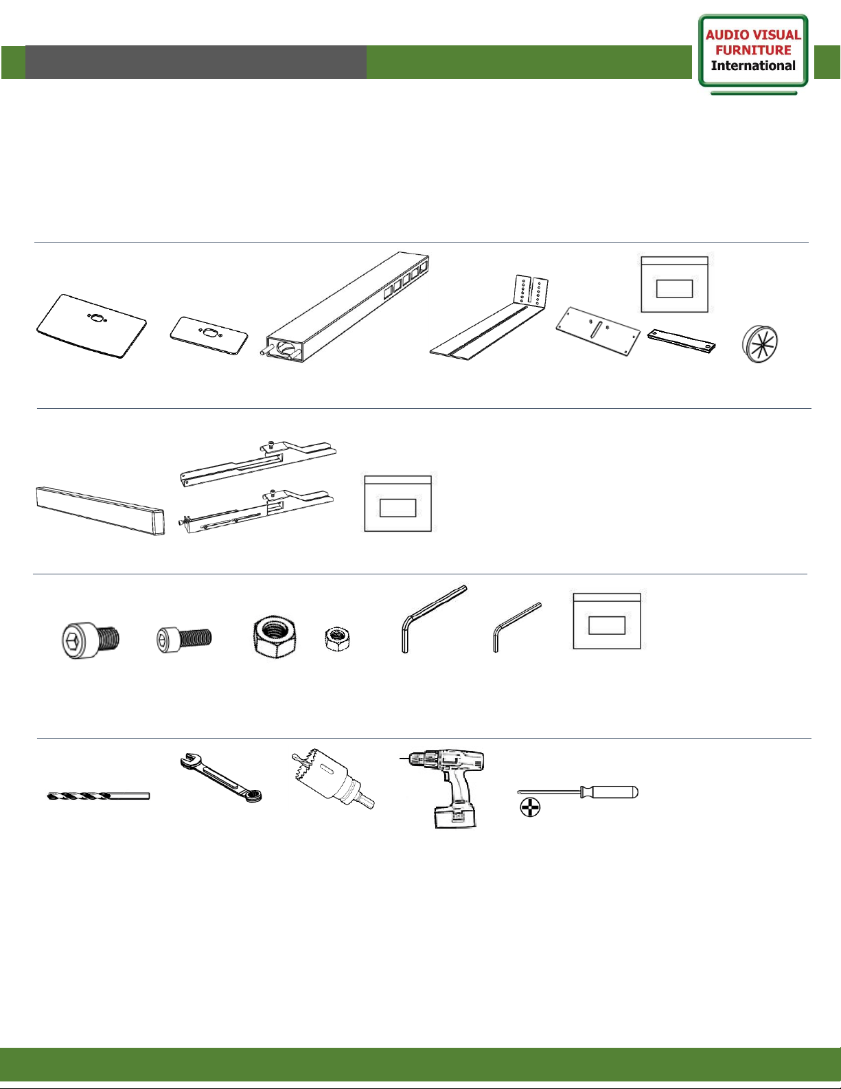
Supplied Parts- Box 1 Main
Rectangular tube
(1)
Supplied Hardware- Bag (PM2-Mount)
M8 X 12
(2)
2
www.video-furn.com
288 Don Hillock Drive |Aurora |Ontario|L4G 0G9 | 1.877.834.3876
M6 X 10
(3)
Base
(1)
Not all hardware supplied will be used, depending on setup and the manufacturer of your display.
Base washer
(1)
Tools required
Tube locker
(1)
Main pillar
(1)
Camera neck
(1)
Camera plate
(1)
Mount Parts- Box 2 Parts and quantity will vary depending on model.
Hardware
bag (1)
PM2-Mount
TV hardware bag
Single (1)-Dual (2)
TV Brackets
Single (2) Dual(4)
Grommet
(1)
M10
Nut
x2
10-32
Nut
x2
M8 Hex key
x1
M6 Hex key
x1
Camera
bag (1)
11mm or
7/16” drill bit
(1)
Wrench or socket
set
(1)
2” hole saw
(1)
Cordless drill/driver
(1)
Phillips screwdriver
(1)
Page 3
4
VF
I
Assembly Instructions
PM2-S/D/XL/CS Mounts
www.video-furn.com
288 Don Hillock Drive |Aurora |Ontario|L4G 0G9 | 1.877.834.3876
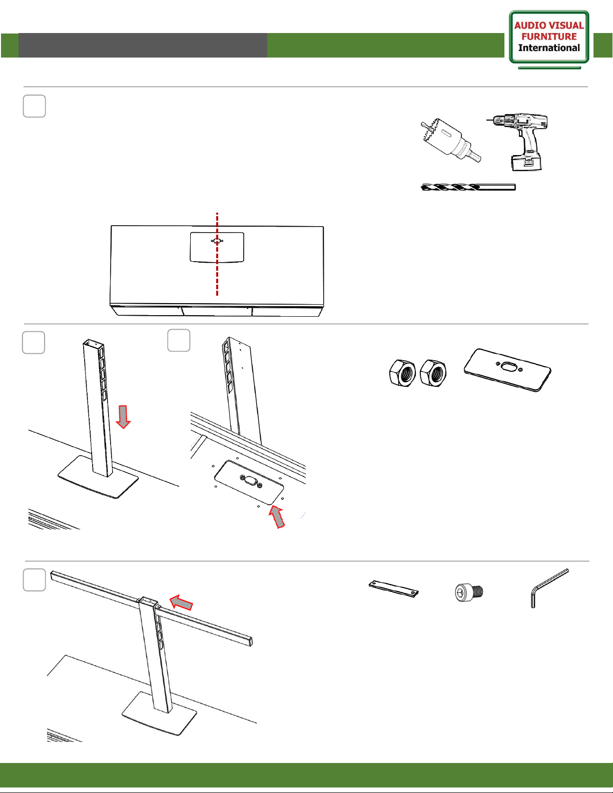
Check furniture from underside to see if partial cuts are there.
(Partial cut is routing 3/4 way thru bottom side)
If so. Use existing cuts as guide , finish cuts all the way through to top.
If not.
A. Center base at desired location, Approx. 3” from back of plate to back of
furniture. Check inside for hole and bolt clearance or interference.
B. Using Base as guide, drill through base round holes and furniture.
C. Mark slot location and drill with hole saw. (remove Base before drilling)
(Most AVFI furniture is precut or partially cut
to accommodate this mount.)
1
2
3
3
2. Slide Main Pillar into drilled holes
(Make sure top holes are at the back for
camera above TV and holes + grommet at
front for camera below TV)(See Step 9* for
details)
3. Attach Base Washer and secure with Nuts
From underneath.
M10 Nuts (2)
Base washer (1)
4. Insert and center mounting tube
through the Main Pillar.
Tube Length will vary depending on
mount used.
Slide in Tube locker over top and secure
Using M8 Bolts and Allen key.
M8 X 12 (2)
Tube locker
(1)
M8 Hex key
x1
Page 4
8
VF
I
Assembly Instructions
4
www.video-furn.com
288 Don Hillock Drive |Aurora |Ontario|L4G 0G9 | 1.877.834.3876
6
7
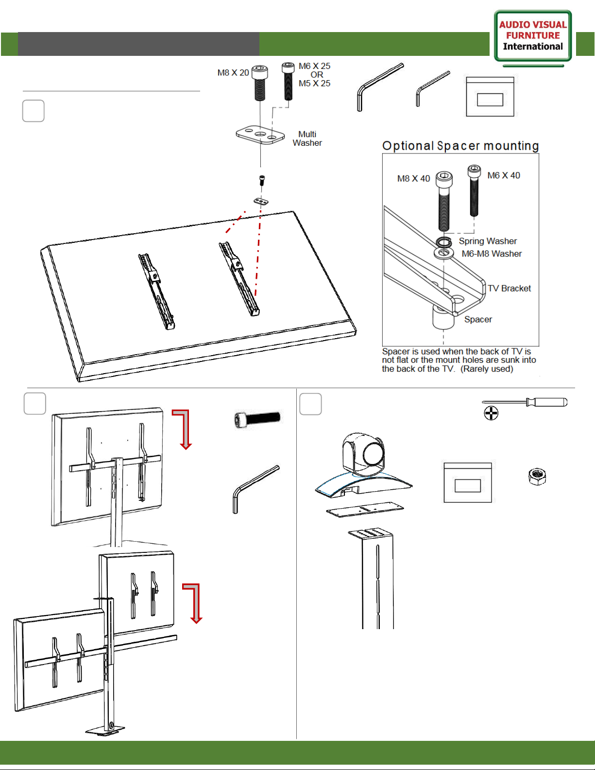
7.With assistance,
lift the TV/s into
position and hook
onto the mounting
tube.
Centre and secure
to the bar with M8
bolts.
Max TV Weight 200 lbs.
(100 lbs each on Dual)
Single
Setup
Dual
Setup
TV 52-70
HW Bag
M8 X 20
(2)
M8 Hex key
x1
Camera
bag (1)
10-32
Nut
x2
Phillips Screwdriver
(1)
8. Attach camera to neck using supplied
1/4-20 bolt in camera hardware bag.
Optional Rectangular camera plate is for
wide base cameras only.
Camera plate is attached with 10-32 nuts
provided.
6.Attach TV brackets to TV
using provided hardware.
Do not overtighten.
PM2-S/D/XL/CS Mounts
Page 5
VF
I
Assembly Instructions
5
www.video-furn.com
288 Don Hillock Drive |Aurora |Ontario|L4G 0G9 | 1.877.834.3876
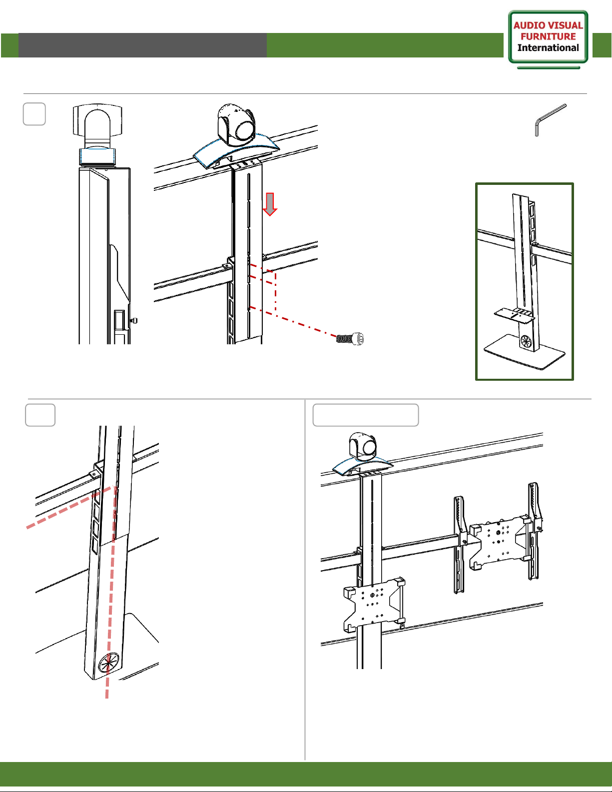
Assembly is complete, enjoy your mount.
9
M6 X 10
(2-3)
9. Adjust Camera neck to
rest on top of TV bezel
and attach using M6 bolts
and Hex key.
*For Camera below TV
The main spine section
Needs to be turned
around in step 2.
-place camera neck with
camera attached under
TV and mark height.
-Remove TV and attach
Camera neck at marked
height. Hang TV.
M6 Hex key
x1
Accessories10
10. Run cables
under tube and
through main Pillar
into furniture below
or out rear
grommet.
A variety of accessories are available to the PM2-Mount
series.
Most will mount centered with the existing rear camera
neck bolt.
Others will mount directly to tube or end of tube.
PM2-S/D/XL/CS Mounts
*
 Loading...