

Page 1
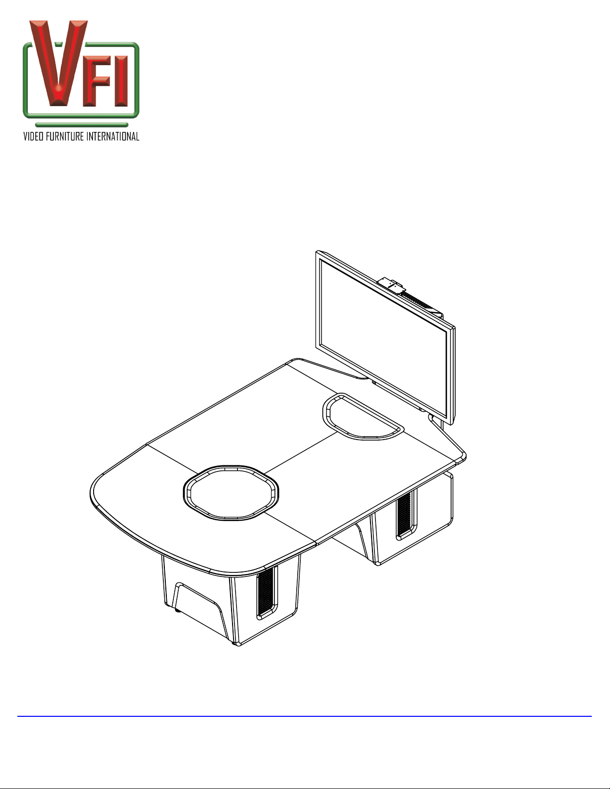
T628-T COLLABORATION TABLE
Assembly and Setup Instructions
Note:
If you cannot understand these instructions or are concerned about safety of the installation
Contact a qualified contractor or contact VFI at 1-877-834-3876.
Confirm all hardware is included before you begin assembly.
Not all hardware supplied will be used depending on the manufacturer of your display/s.
Page 1
of 8
VIDEO FURNITURE INTERNATIONAL
190 Don Hillock Drive Aurora , Ontario L4G 0G9 www.video-furn.com
Toll Free: 1-877-834-3876 Fax: 1-905-751-1488 Local:905-751-1459
Page 2
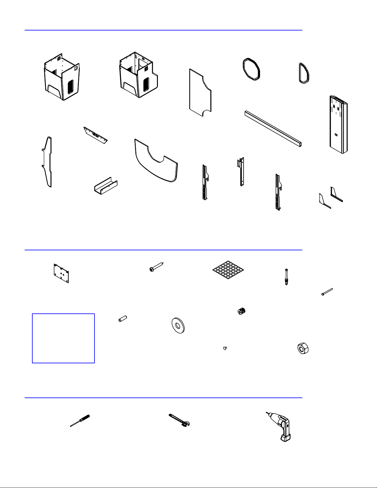
SUPPLIED PARTS
Page 2
of 8
Table base front
(1)
Rack Gable
(3)
Bridge Cap
(1)
SUPPLIED HARDWARE
Management bridge
Cable
Table base rear
(1)
324 Table top
(1)
E324 Table top
Right Side (1)
Left Side (1)
(1)
PM2_3
(1)
Round Island
(1)
PM2 Tube
(1)
WB1
(2)
PM2_3
WITH LOCK
A-Island
(1)
TE-800 Tower
(1)
9160-10
(1)
(1)
#8 x 1"
Mending Plate
(11)
TV
Hardware
Bag
(1)
TOOLS REQUIRED (not included)
Phillips (+)
screw driver
Particle board screw
5/16 x 1"
Dowel
(10)
(64)
5/16 Washer
(2)
Adjustable
Wrench
Sticker BLK
(1 sheet)
1" TITUS Cam
(12)
5/16-18 x 2.5
RHSN Bolt
(2)
TITUS Pin
(42)
1/4 x 20 x 1/2
Hex Bolt
(5)
5/16-18 Hex nut
(2)
Cordless drill
w/ phillips (+) bit
Page 3
Page 3
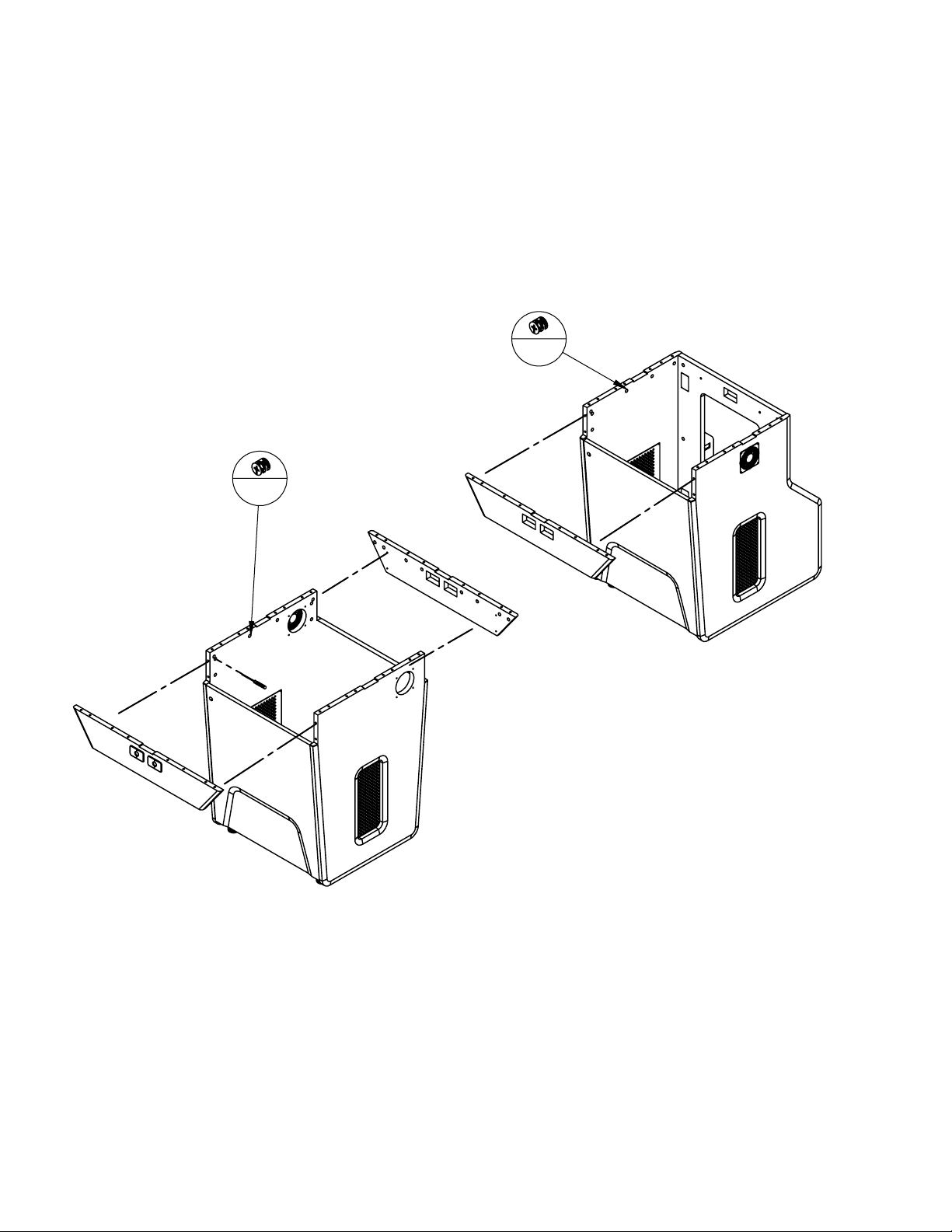
1. Align the pins of the brace into the holes and ensure brace seats flush before
tightening
2. Tighten the quarter turn one quarter turn until piece is tight
3. Repeat for remaining braces
12
16
of 8
Page 4
Page 4
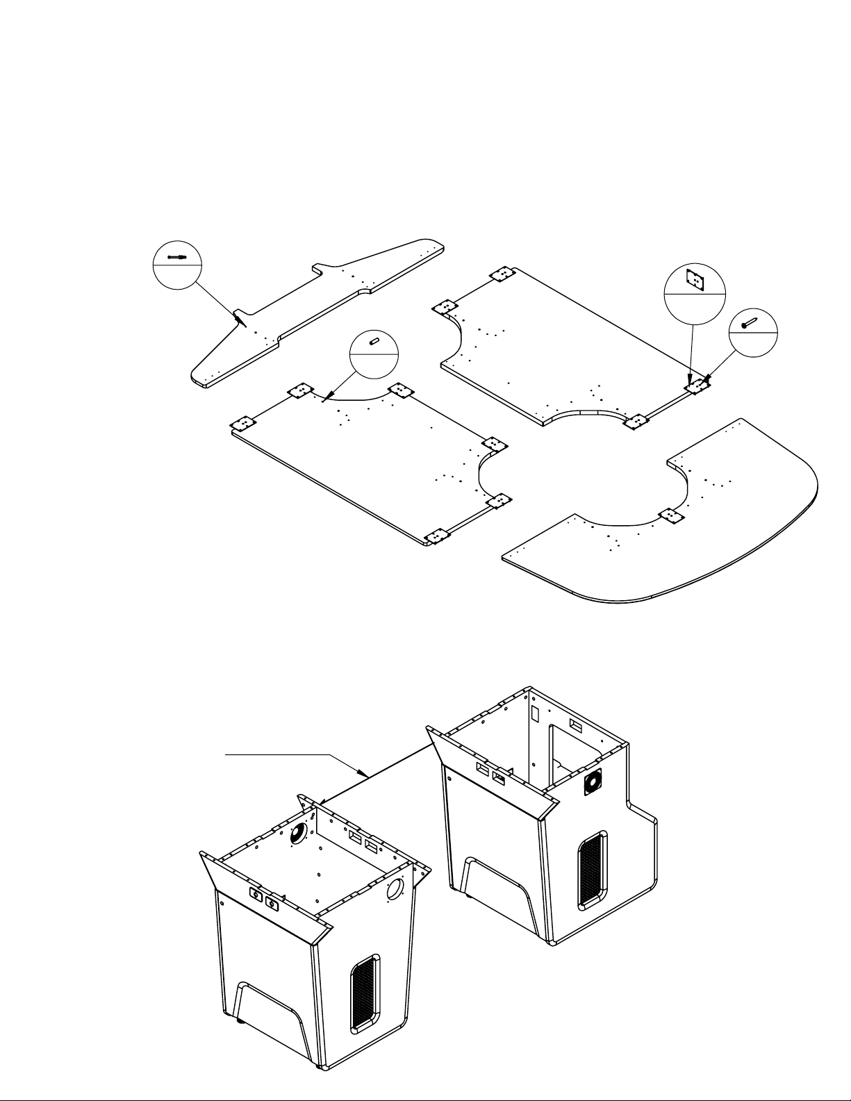
4. Lay out the table tops and fasten the mending plates as indicated securing them
with the wood screws provided
5. Using a cordless drill and a phillips (+) bit secure the cam pins into the pre-drilled holes
6. Insert Dowels into pre-drilled holes and esure they are fully seated
36
11
32
10
of 8
7. Align both pre-assembled pods approx. 26" apart in the desired location
26" Spacing
Page 5
Page 5
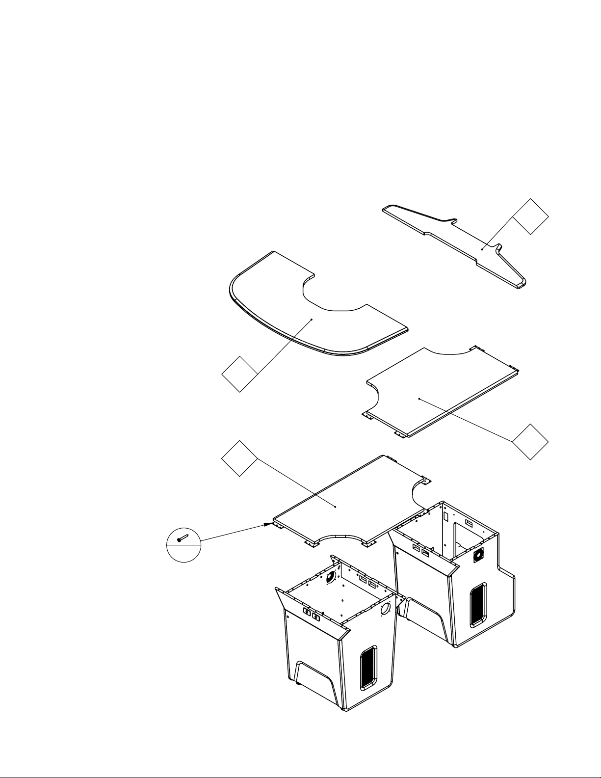
8. In the order indicted place each table top piece one at a time and ensure
the pins and dowels are properly seated
9. Using a phillips (+) screw driver turn cams one quarter turn until tight
10. Only place addition pieces when the previous pieces have been properly secured
11. Secure all tops to the mending plates using the wood screws provided
of 8
4
20
3
2
1
Page 6
Page 6
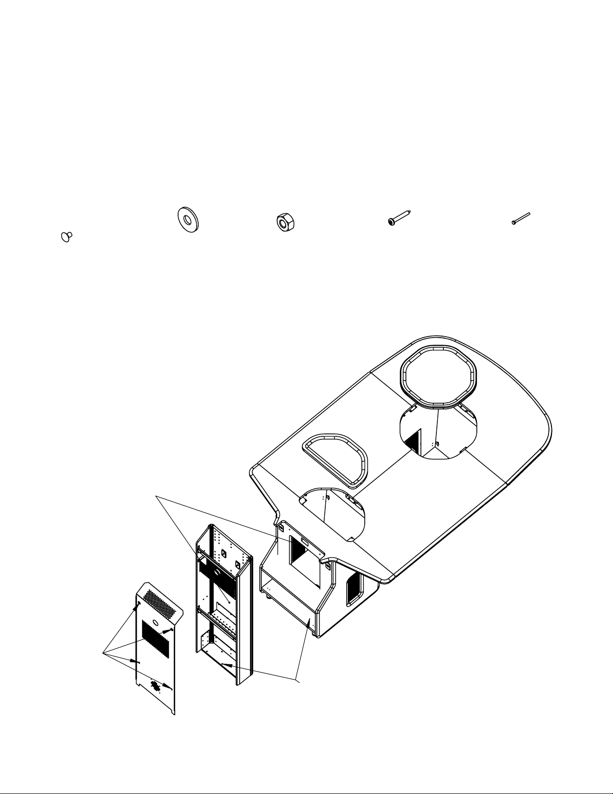
12. Place cut outs into available spaces and secure to mending plates using
the wood screws provided
13. Remove the back panel of the TE800 by removing the screws and set it aside
14. Position the TE800 unit onto the base and align the base holes
15. Secure the units with the bolts provided
16. Re-attch the TE800 back panel after all routing of wires is complete
5/16 -18 x 2.5
RHSN Bolt
(2)
5/16 washer
(1)
5/16-18
Hex nut
(2)
#8 x 1"
Particle board
screw
(12)
1/4 x 20 x 1/2
Bolt
(5)
of 8
Panel
screws
Lag bolt
location
Base
holes
Page 7
Page 7
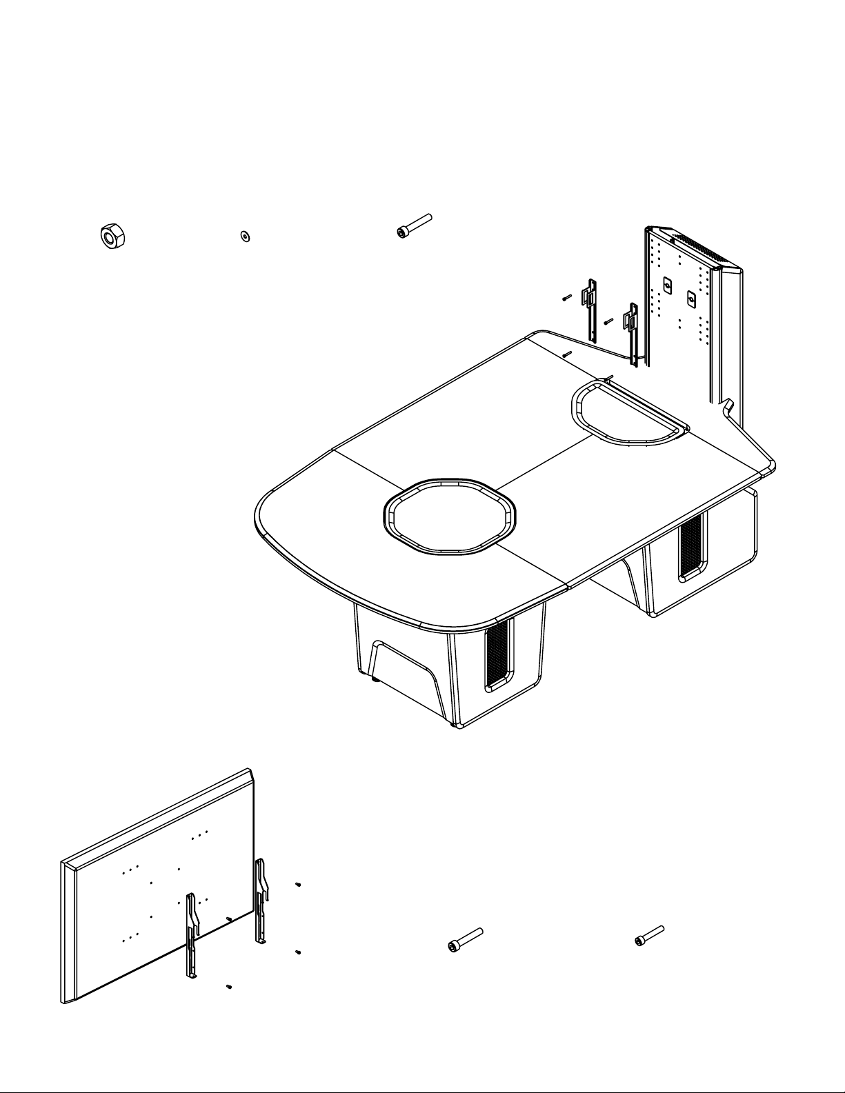
18. Attach the mounting brackets to the TE800 using a measuring tape for proper
height placement
19. Secure using provided hardware
of 8
M8 nut
(4)
M8 washer
(4)
M8 Socket Head
Cap Screw
(4)
20. Mount the TV Brackets to your TV using the
M8 or M6 Bolts provided
WARNING: Over tightening these bolts can result
in damage to your TV
M8 Socket head
cap screw
(4)
M6 Socket head
OR
cap screw
(4)
Page 8
Page 8
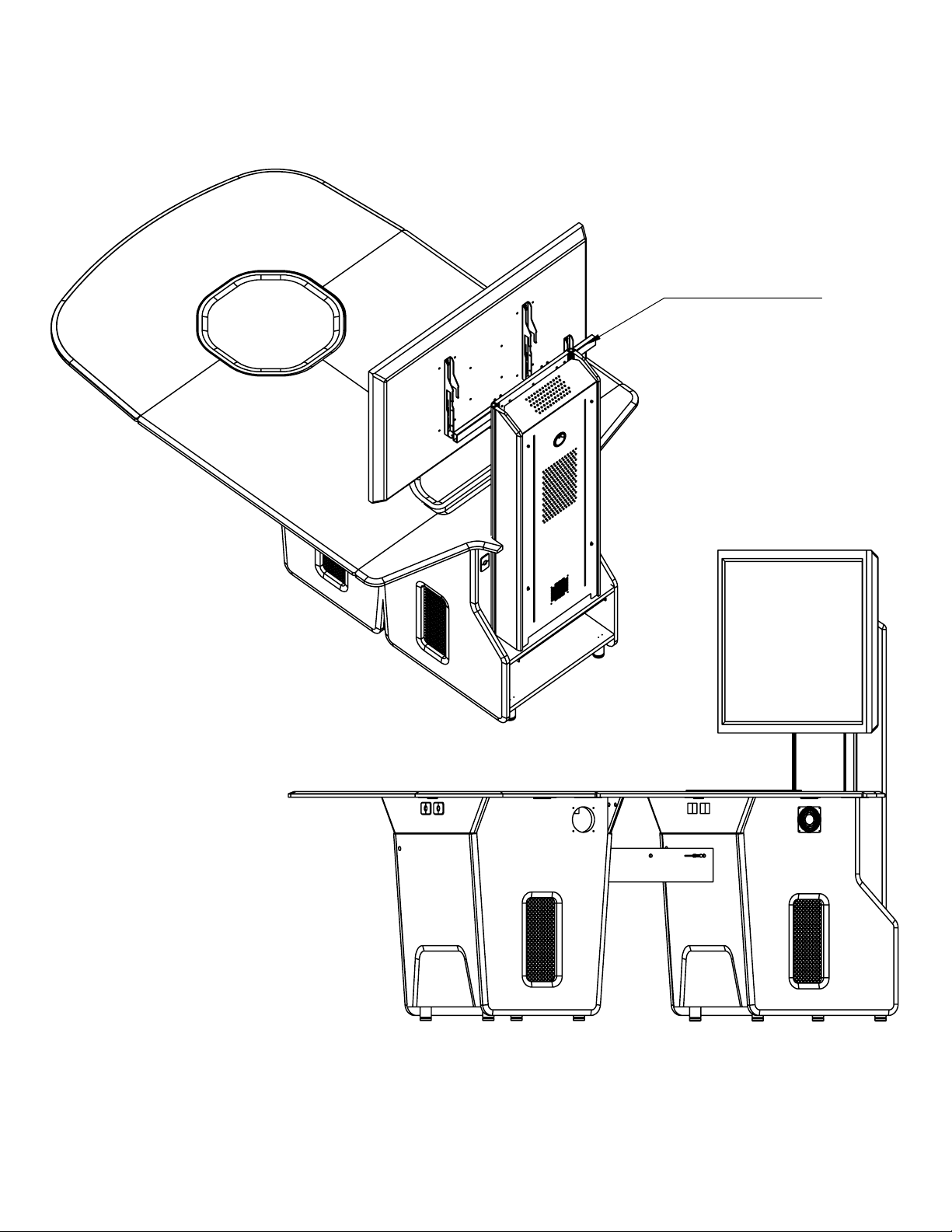
21. Insert the mounting bar into the TE800 brackets and centre using a measuring
tape
22. WITH ASSISTANCE lift and mount the TV onto the bar and centre it on the mount
MOUNTING BAR
of 8
23. Postion the assembly cable management bridge into postion under the table
24. Using a phillips screw driver (+) turn cams one quarter turn until tight
25. Ensure BOTH sides of the bridge are secure
 Loading...