

Page 1
PM-S and PM-D
Assembly and mounting Instructions
Thank you for purchasing VFI's universal display mounting system.
These products are designed for tabletop mounting of a single or dual plasma/lcd
TV's sized 32-50+" and weighing no more than 160lbs each.
Some larger TV's will fit, Download TV manufacturers specs online,
max hole location is 700mm wide x 440mm high
2 persons are required to attach plasma/lcd TV's to this mount.
Note:
If you cannot understand these instructions or are concerned about safety of the installation
Contact a qualified contractor or contact VFI at 1-877-834-3876.
Confirm all parts are included before you begin assembly.
Not all hardware supplied will be used depending on the manufacturer of your display/s.
Read these intructions start to finish before beginning installation.
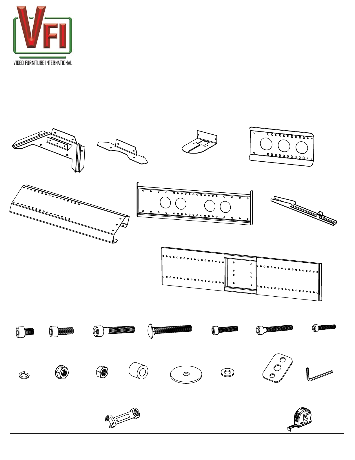
Supplied Parts:
Camera Tongue
Mounting Base
(1)PM-S
Base Extension
(1) PM-S
(1) PM-S
Camera Mount Neck
(1) PM-S
Page 1
of 8
Mounting Spine
(1)PM-S
Note:
to the PM-D box to assemble a PM-D.
(+)Items only come in the PM-D box.
You will need the PM-S box in addition
Supplied Hardware:
M8 x 12
(10) PM-S
Spring Washer
(12) PM-S
(+4) PM-D
M8 x 20
(10) PM-S
(+12) PM-D
M8 Lock Nut
(4) PM-S
(+8) PM-D
5/16 Nut
(6) PM-S
Mounting Bracket
(1)PM-S
(+1)PM-D
Dual Bracket Support
(+1)PM-D
(1) in PM-S Bag , (+1) in PM-D Bag
M8 x 40
(4) PM-S
(+4) PM-D
Spacer
(4) PM-S
(+4) PM-D
5/16 Carriage Bolt
(6)PM-S
Large Washer
(6) PM-S
M6 x 25
(4) PM-S
(+4) PM-D
M5-M8 Washers
(14) PM-S
(+14) PM-D
TV Bracket
(2)PM-S
(+2)PM-D
M6 x 40
(4) PM-S
(+4) PM-D
Multi Washer
(4) PM-S
(+4) PM-D
M5 x 25
(6) PM-S
(+6) PM-D
Hex Keys
6,5,4mm
(3) PM-S
Tools required:
(not supplied)
VIDEO FURNITURE INTERNATIONAL
190 Don Hillock Drive, Aurora , Ontario L4G OG9 www.video-furn.com
Toll Free: 1-877-834-3876 Fax: 1-905-751-1488 Local:905-751-1459
Wrench or Socket (2) Tape
9/16inch
Measure
13mm
1.9
Page 2
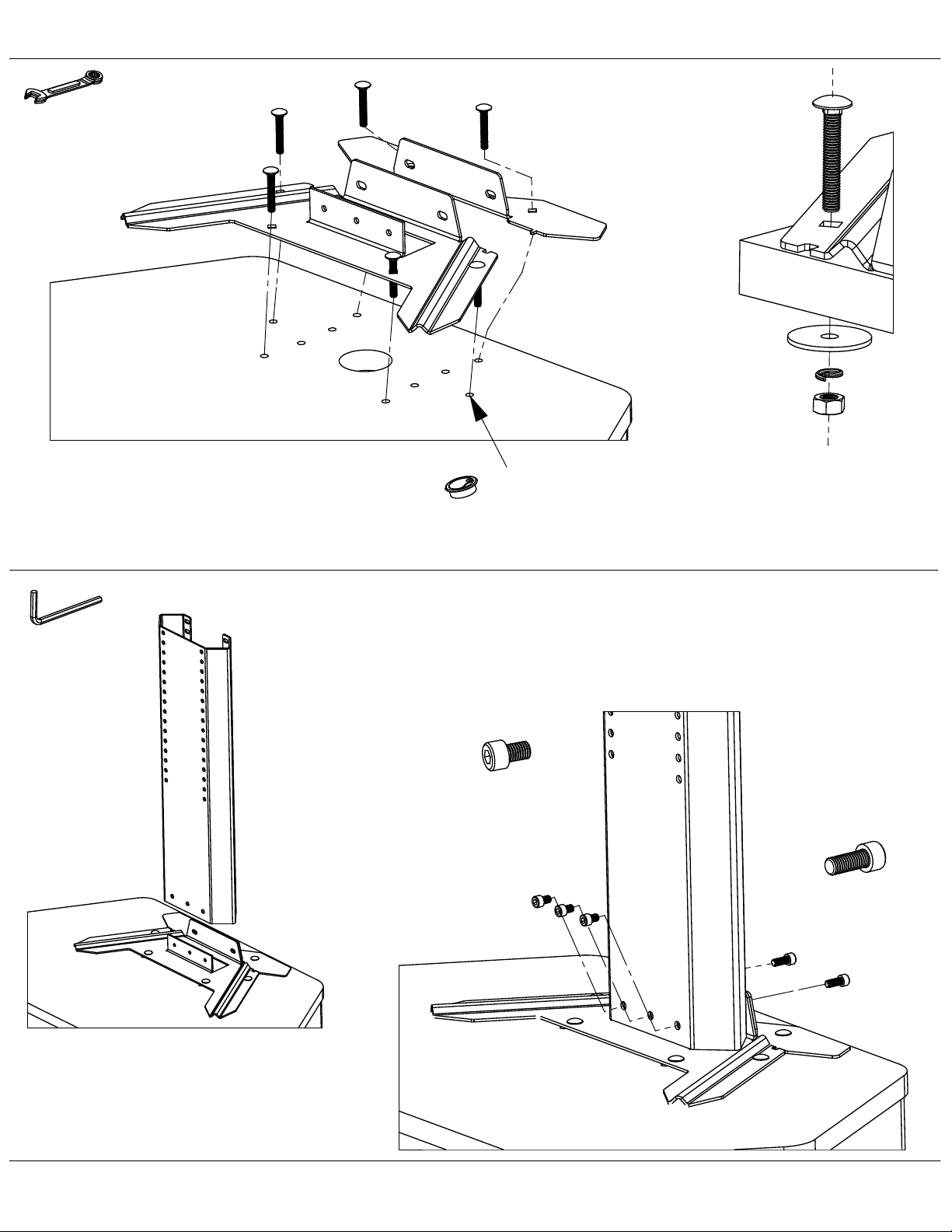
Step 1
9/16 Wrench
or Socket
Securing the Base to a cart or table
5/16 Carriage Bolt
Mounting
Base Part
Table/Cart
Large Washer
Page 2
of 8
Shown Mounting to
VFI cart PL3070
Tighten all 6 nuts securely
Step 2
6mm Hex Key
Adding the Mounting Spine
L
1
Spring Washer
5/16 Nut
If your cart/table does not have pre-drilled holes.
See Page 8 for optimal placement of base.
1. Insert Mounting Spine into Base as shown
2. Add the back bolts first. Do not tighten till front and back
bolts are in place.
3. Use your 6mm hex key to tighten all 5 bolts
Remove grommet if present, surface must be flat.
M8 X 12
: Optional Base shroud can be
Note
inserted over-top at the end of Step 2.
see bottom of page 8 for description.
VIDEO FURNITURE INTERNATIONAL
190 Don Hillock Drive, Aurora , Ontario L4G OG9 www.video-furn.com
Toll Free: 1-877-834-3876 Fax: 1-905-751-1488 Local:905-751-1459
2
M8 X 20
3
Page 3
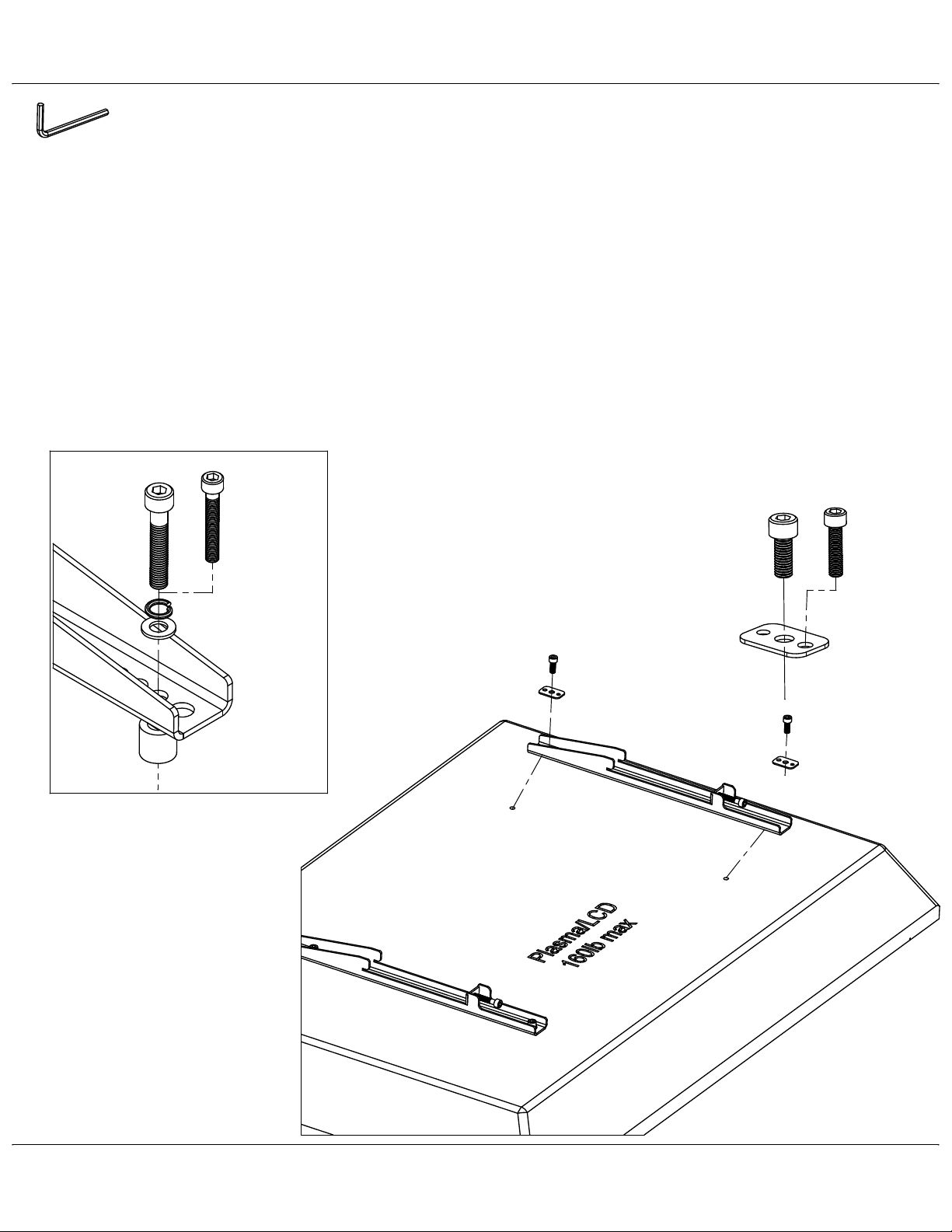
Attaching TV BracketsStep 3
1.Place TV face down on blanket or non abrasive surface such as cardboard.
Page 3
of 8
Hex Keys
2.Check to see if your TV came with mounting hardware or not.
If not,we have supplied the most common hardware.
Most displays under 42" will use the M6 bolt. Most 42"+ will use the M8 bolts.
See which bolt length you need by hand tightening only.
3.Place TV brackets so you can see the TV mounting holes through the bracket
and insert bolt through appropriate washer and spring washer.
4.Use the Hex key to tighten until there is resistance, then give a half turn.
DO NOT OVERTIGHTEN AS THIS CAN DAMAGE OR PUNCTURE THE TV
.Have 2 people lift the TV as it can be very heavy and awkward.
Note
Some TV's require non standard hardware.
This bracket was made to accomodate up to M10 bolts which can be found
at your local hardware store along with longer versions of the included hardware.
Optional Spacer mounting
M8 X 40
M6 X 40
M8 X 20
M6 X 25
OR
M5 X 25
Spring Washer
M6-M8 Washer
TV Bracket
Spacer
Spacer is used when the back of TV is
not flat or the mount holes are sunk into
the back of the TV. (Rarely used)
Multi
Washer
VIDEO FURNITURE INTERNATIONAL
190 Don Hillock Drive, Aurora , Ontario L4G OG9 www.video-furn.com
Toll Free: 1-877-834-3876 Fax: 1-905-751-1488 Local:905-751-1459
Page 4
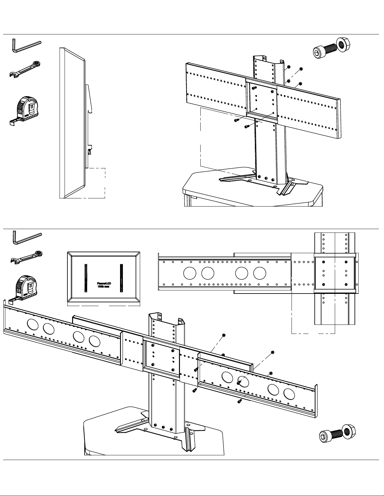
Step 4-D
Dual Bracket Support (PM-D only)
(PM-S go to Next Page)
6mm Hex Key
13mm Wrench
or Socket
A B
=
+ 4"
Bolt to the nearest upper hole.
B
A
Page 4
M8 X 20 with Locknut
of 8
Step 4.5-D
6mm Hex Key
13mm Wrench
or Socket
Locating and Installing Mounting brackets
C D=
( - 29.5")divided by 2
Bolt to the nearest outward hole.
Some tolerance will remain for adjusting.
D
: You will need the PM-D
Note
hardware bag in addition to the
PM-S hardware bag to complete
this step.
C
M8 X 20
VIDEO FURNITURE INTERNATIONAL
190 Don Hillock Drive, Aurora , Ontario L4G OG9 www.video-furn.com
Toll Free: 1-877-834-3876 Fax: 1-905-751-1488 Local:905-751-1459
Lock Nut
Page 5
6mm Hex key
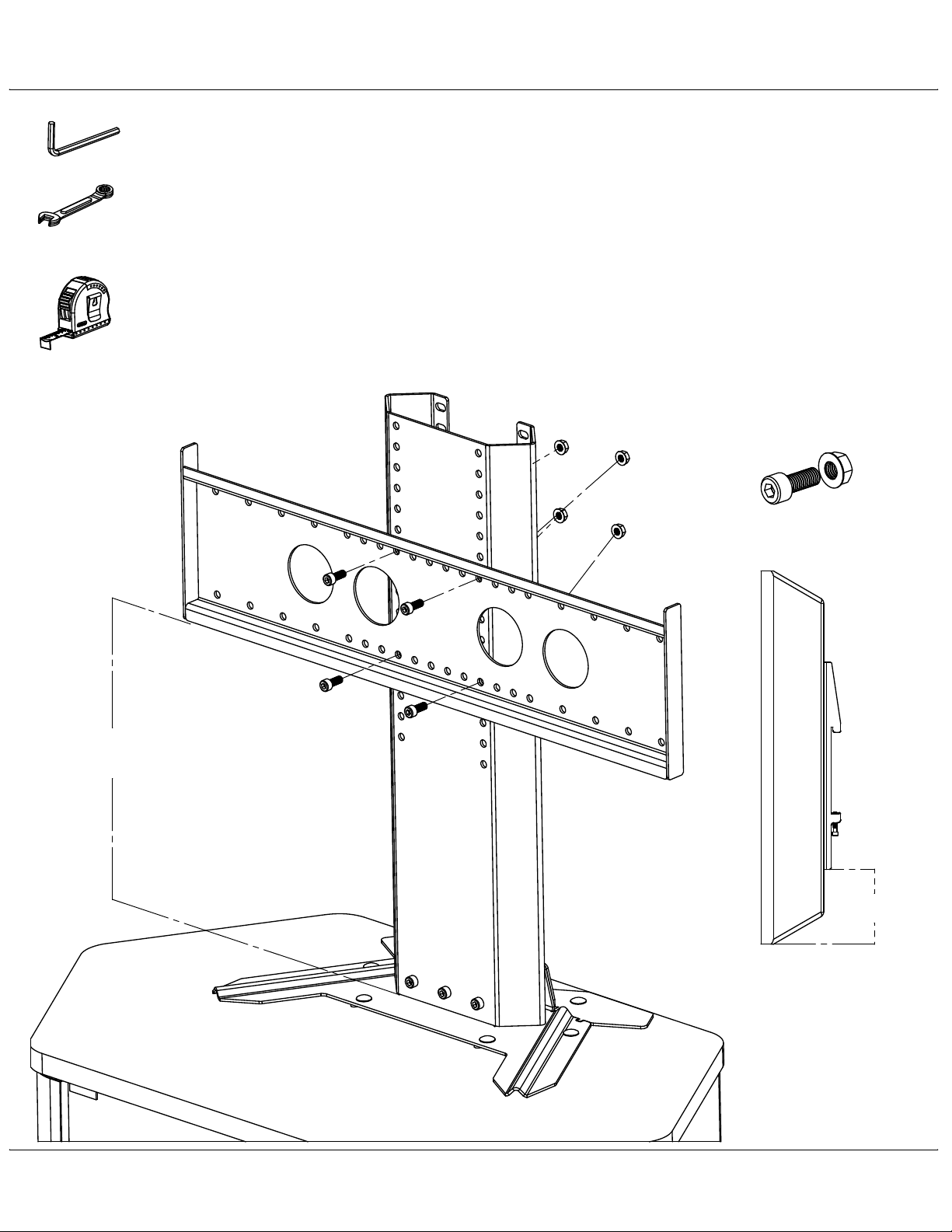
Mounting Bracket (PM-S only)Step 4-S Page 5
1.Figure out the location of the bracket.
B=
+ 4" (see below where to measure B distance)
A
Bolt to the nearest upper hole.
2.Make sure to center the bracket.
of 8
13mm Wrench
or Socket
3.Tighten all 4 bolts.
M8 X 20 with Locknut
A
B
VIDEO FURNITURE INTERNATIONAL
190 Don Hillock Drive, Aurora , Ontario L4G OG9 www.video-furn.com
Toll Free: 1-877-834-3876 Fax: 1-905-751-1488 Local:905-751-1459
Page 6
Step 5
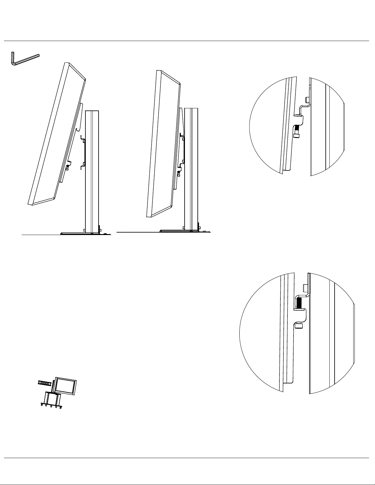
Hanging TV's and locking into place Page 6
of 8
6mm Hex key
Note:
PP
heavy and awkward.
2 people should lift and secure the TV as it can be
P
L
2
Make sure Bolt clears bracket, TV will tilt
until its flush with the mount, Tighten bolt
until it catches on the bracket.
Hang the TV , First hooking the top of the Mounting Bracket
1
rail then allowing the TV to rest on the rail.
PM-D
Never leave one TV attached.
Always have someone support the
attached TV as the other side is
hung. This may require 3 people.
PPP
3
Once your TV is centered.
Completely tighten bolt against
metal bracket.
VIDEO FURNITURE INTERNATIONAL
190 Don Hillock Drive, Aurora , Ontario L4G OG9 www.video-furn.com
Toll Free: 1-877-834-3876 Fax: 1-905-751-1488 Local:905-751-1459
Page 7
Step 6
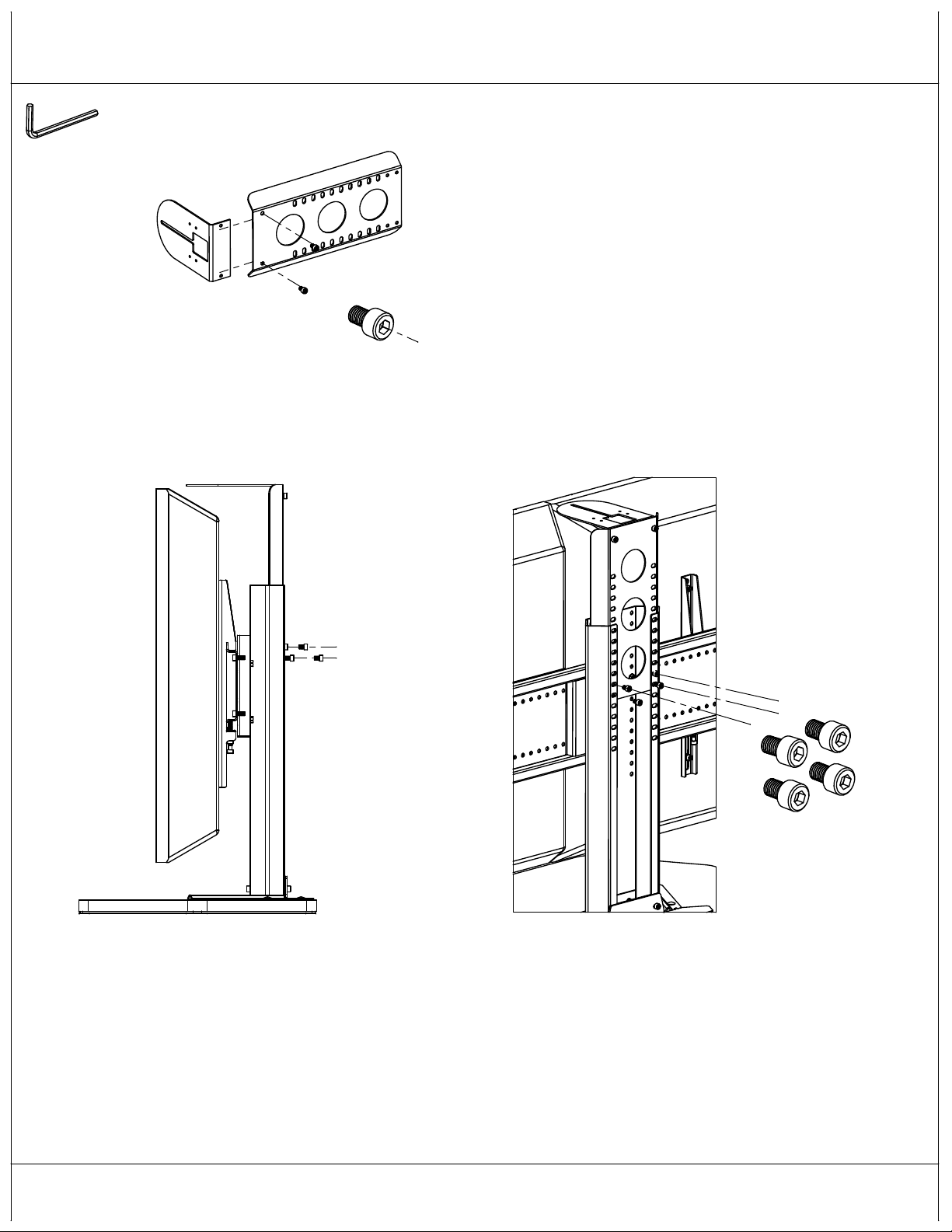
The Camera mount
1. Bolt tongue to camera mount neck
Page 7
of 8
6mm Hex key
L
2. Insert mount neck into mounting spine until tongue is
approximately 1-2" from the top of the TV.
3. Bolt camera mount neck into mounting spine.
Tongue is now ready for camera.
M8 X 12
2
3
M8 X 12
VIDEO FURNITURE INTERNATIONAL
190 Don Hillock Drive, Aurora , Ontario L4G OG9 www.video-furn.com
Toll Free: 1-877-834-3876 Fax: 1-905-751-1488 Local:905-751-1459
Page 8
Step 7
Finishing
TV's hidden for
mount visibilty.
Page 8
of 8
PM-D
Congratulations! you're done.
You will notice you have a bit of hardware left over
which you may need in the future.
We suggest placing this in a small bag and taping it
inside the bottom back of the spine.
(A PM-S can be upgraded to a PM-D by ordering a PM-D expansion box)
If you have any problems,questions or suggestions, we value
your feedback. Toll free 1-877-834-3876
center
3
center
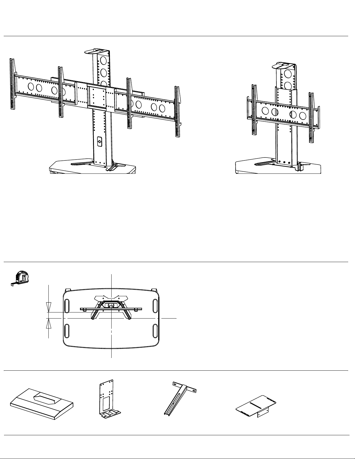
Optimal placement of base.
If your cart did not have pre-drilled holes and you need
to locate the mount:
Remove grommet if present, surface must be flat.
Place base 3" back from center.
Mark hole center locations with punch or pencil
Drill through with an 3/8 drill.
Place base and insert all 6 Carriage bolts to confirm holes.
PM-S
Optional accessories
PM-CVR
Base cover (2 pc)
High Def Codec Bracket
VIDEO FURNITURE INTERNATIONAL
190 Don Hillock Drive, Aurora , Ontario L4G OG9 www.video-furn.com
Toll Free: 1-877-834-3876 Fax: 1-905-751-1488 Local:905-751-1459
PM-HDCB
PM-CAM (PM-D only)
eye level cam mount
See www.video-furn.com for
latest optional accessories.
PM-CMP
Codec mounting plate
 Loading...