

Page 1
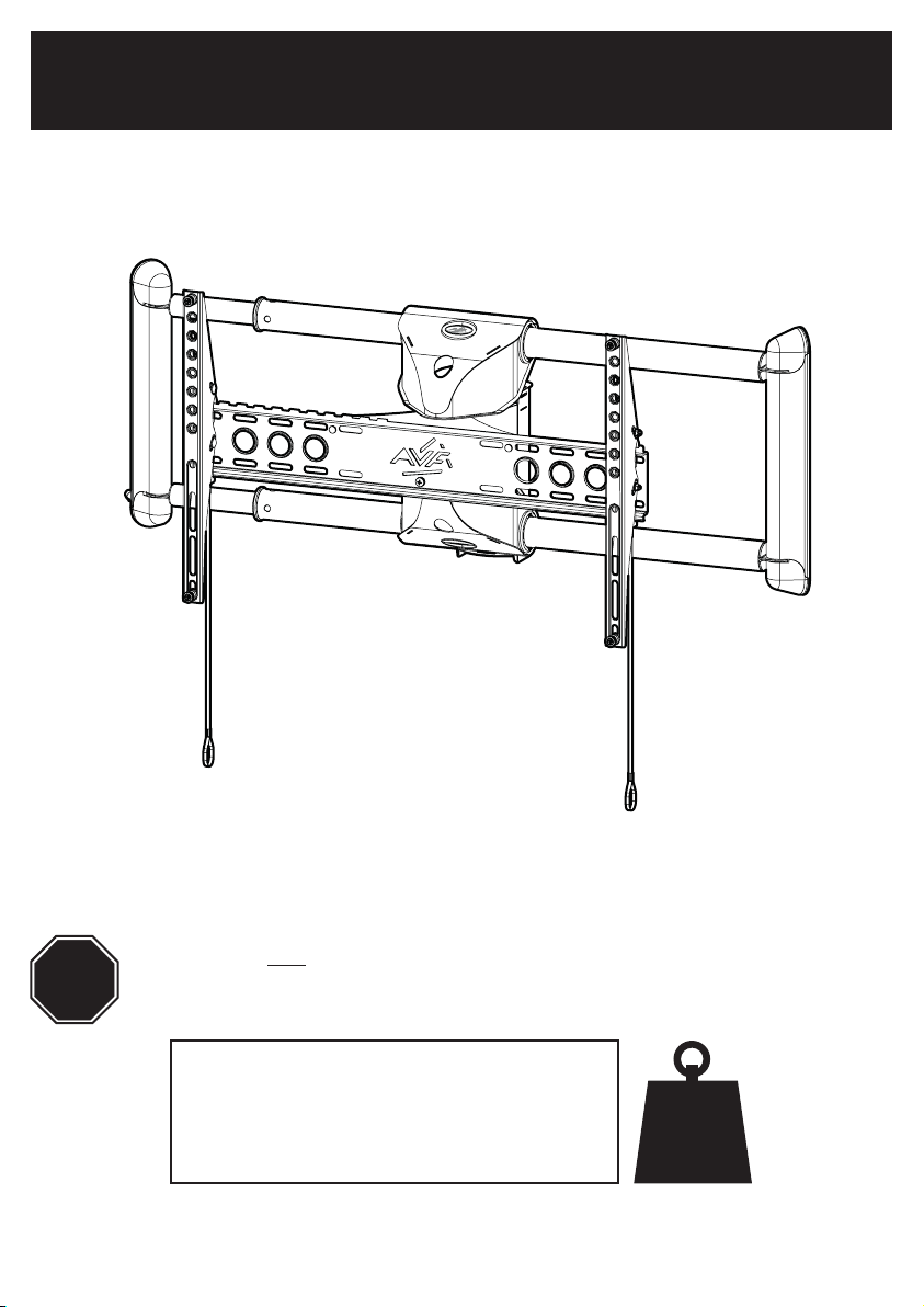
467730 rev00
Read through ALL instructions before commencing installation.
STOP
If you have any questions about this product or issues with installation contact
the customer services help line before returning this product to the store.
CUSTOMER SERVICES HELP LINE NUMBER:
+44 (0) 333 320 0463 (UK)
1-800 667 0808 (USA)
AVF Group Ltd. Hortonwood 30, Telford, Shropshire, TF1 7YE, England
AVF Group, Inc. 2775 Broadway, Cheektowaga, Buffalo, New York, 14227 USA
www.avfgroup.com
50kg
110lbs
Page 2
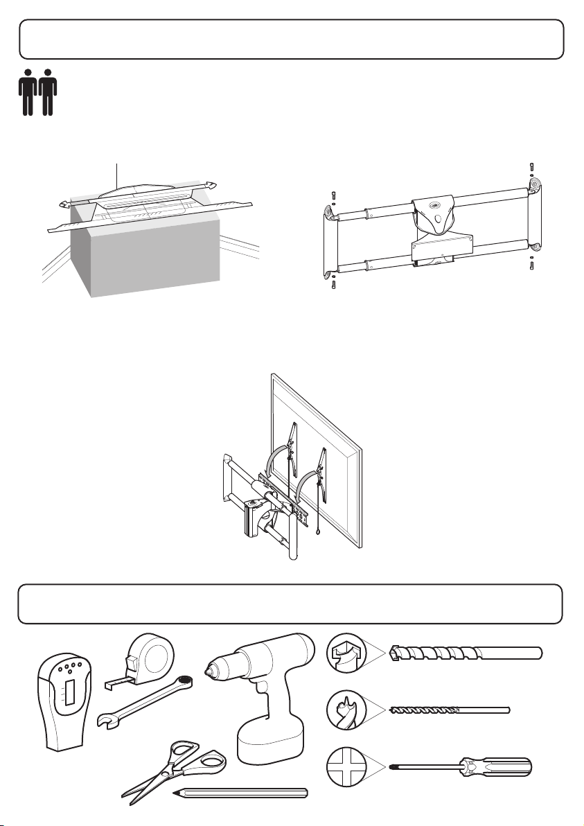
Assembly Overview
2 Person Installation Recommended
Determine TV and Cornermount position
Fit Support Arm Assembly
Connect TV
Stud Finder
8mm & 13mm
Tools Recommended
Ø12mm (15/32")
Masonry
Ø5mm (3/16")
Wood
Page 3
Measure the TV fixing holes Width and Height
1
Fitting the TV Brackets
2
Determine TV and Cornermount position
3
Determine TV and Cornermount Height
4
Fitting the Support Arm Assembly
5
Fitting the TV Bracket
6
Connecting the TV
7
Index
Retain all packaging in case the bracket needs to be returned.
Contents may vary from photography/ Illustrations.
You will not need all these parts, so expect there to be some left over depending upon the specification of your TV.
This product is intended for indoor use only. Use of this product outdoors could lead to failure and personal injury.
It is the responsibility of the installer to ensure that the mounting wall is of a suitable standard and void of any services
(eg gas, electricity, water etc).
AVF accept no responsibility for any damage or loss caused by installing this product in a sub standard wall.
Page 4
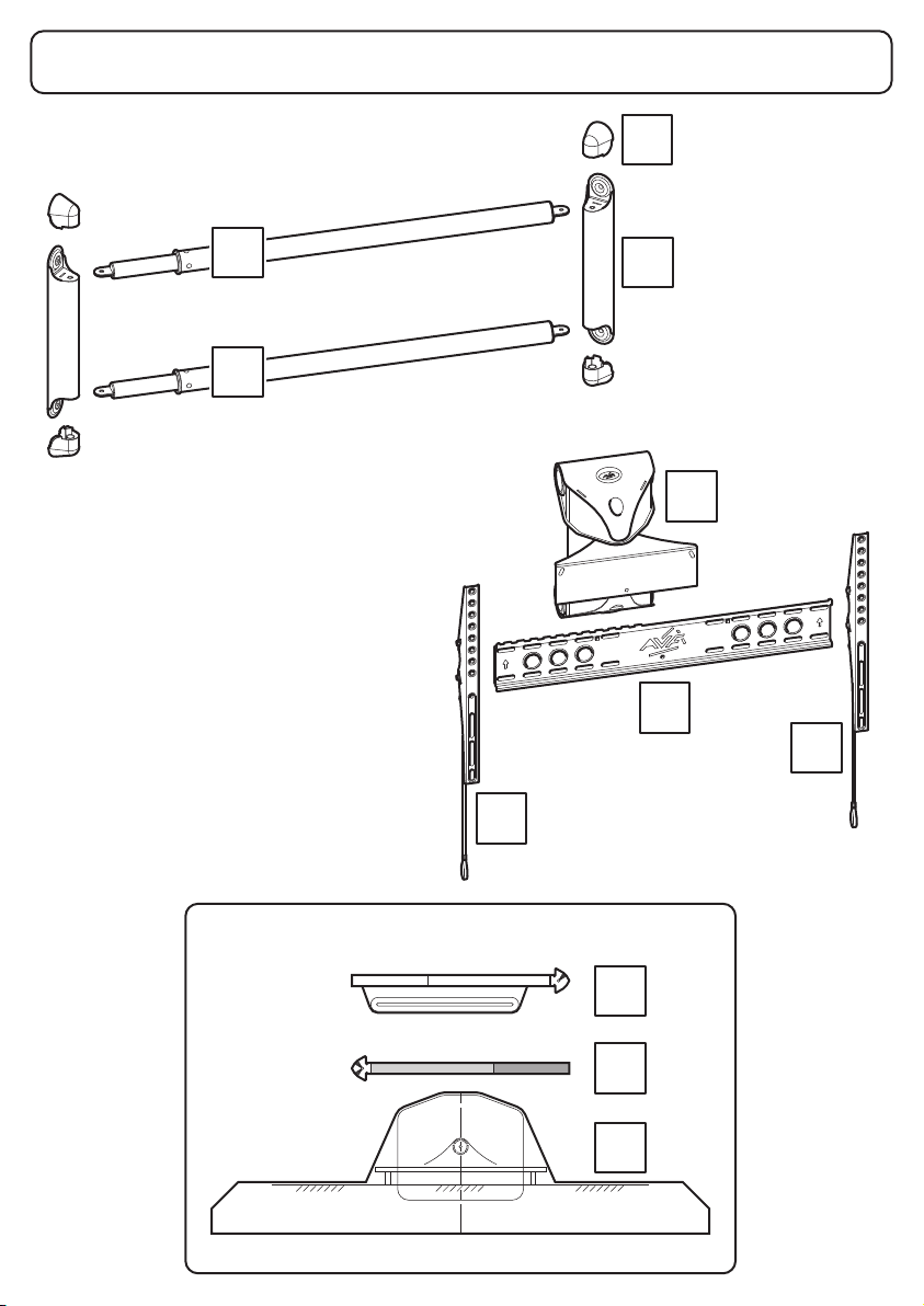
Boxed Parts
L
x4
G
G
B1
H
x2
C
A
B2
Templates
PT1
PT2
PT3
Page 5
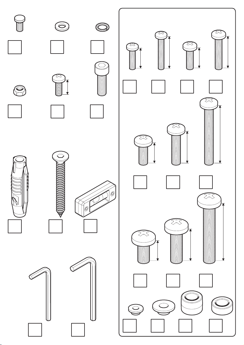
TV Screws, Reducers and Spacers
N
P1
M6
M6
x2
x2
O1
M6
Q
M6
x3
x1
16mm
O3
M8
S
M8
x4
x4
M4
U1
x4
M6
U5
16mm
x4
M4
U2
16mm
x4
M6
U6
25mm
M5
U3
x4
x4
25mm
16mm
M6
U7
M5
U4
x4
25mm
x4
45mm
X1
x4
Z1
5mm
x1
X2
x4
Z2
6mm
Y
x1
x1
V1
M8
U8
x4
x4
V2
16mm
U9
x4
M8
x4
W1
25mm
U10
x12
M8
x4
W2
45mm
x4
Page 6
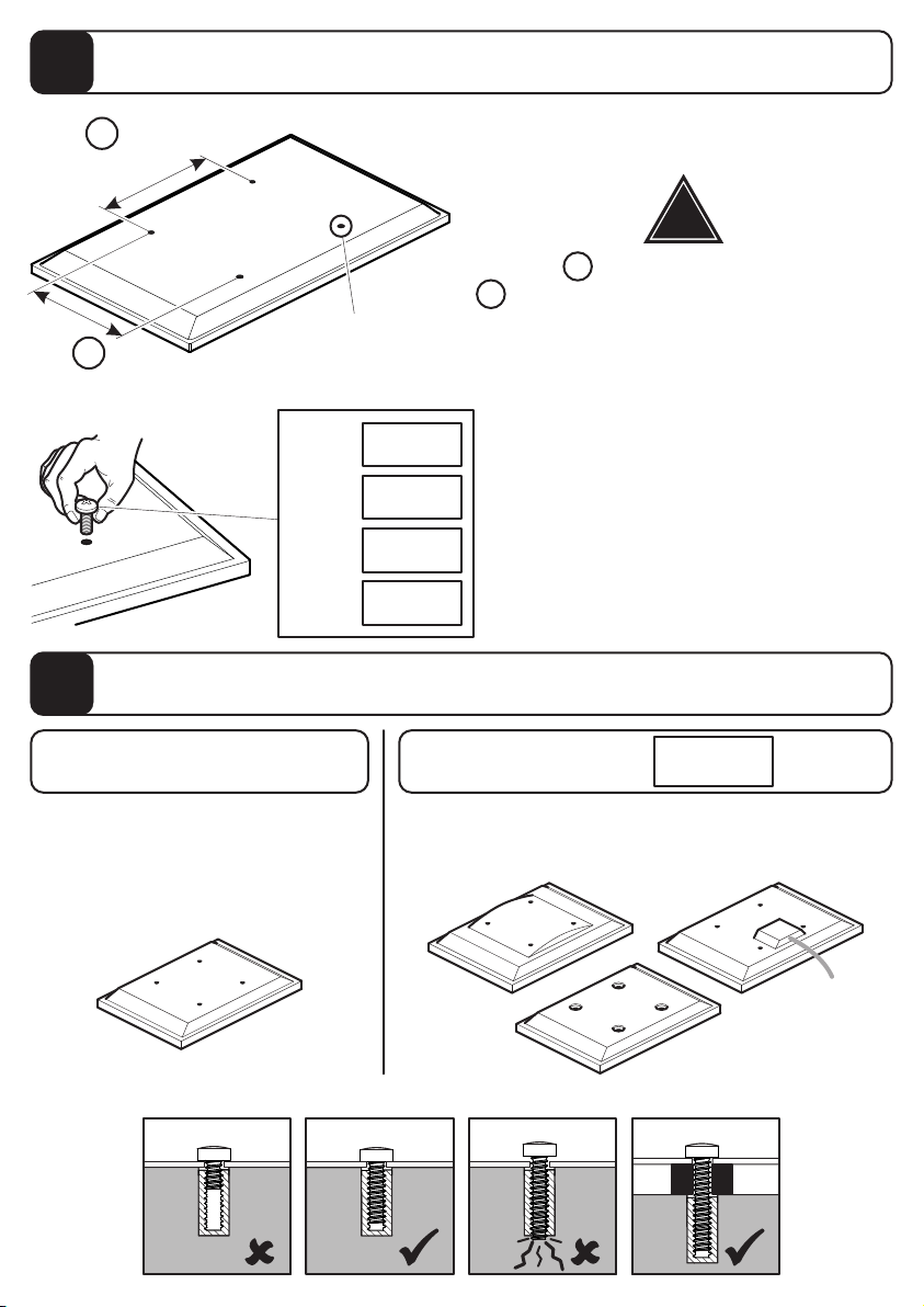
Measure the TV fixing holes Width and Height
1
X
50 - 600mm
!
TV Fixing Holes
Y
50 - 400mm
M4 =
M5 =
M6 =
M8 =
Fitting the TV Brackets
2
For TVs with flat / unobstructed back
If width X is greater than mm or height
Y greater than mm STOP installation now
and contact the customer help line
400
U1/U2
You are provided with 4 diameters of TV
U3/U4
U5-U7
fixing screws, M4, M5, M6 and M8.
Determine the screw diameter that fits and
remember for step 2.
U8-U10
SpacersNo Spacers
For TVs with irregular / obstructed back
600
W1/W2
TV
TV
WARNING
TV
TV
Page 7
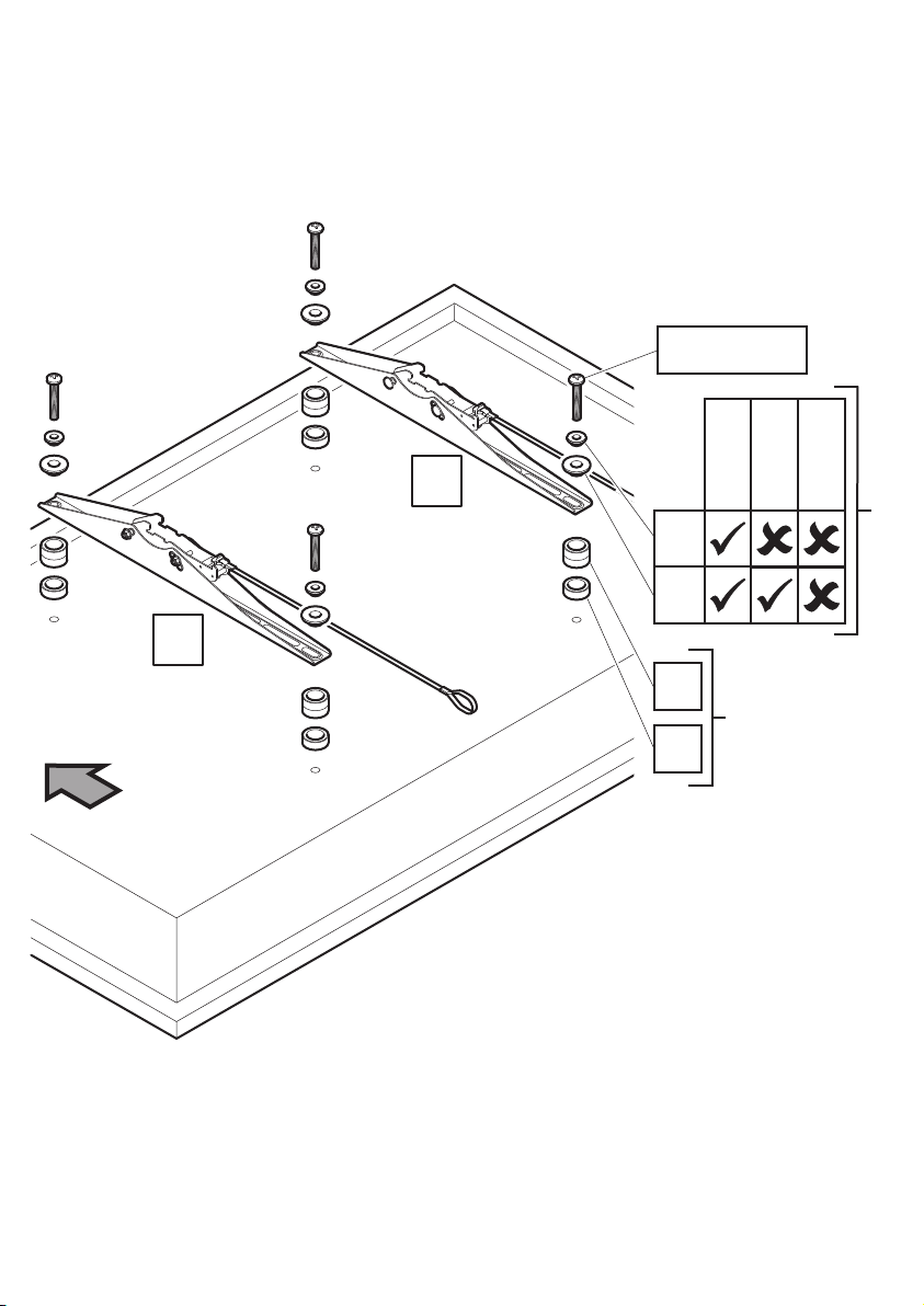
U1 - U10
Top
B2
B1
V1
V
W
W2
2
1
U1-U2
U3-U7
If required
U8-U10
Do you need V1 or V2?
Attach the bracket to the back of your TV using suitable screw, reducer and spacer combinations.
Page 8
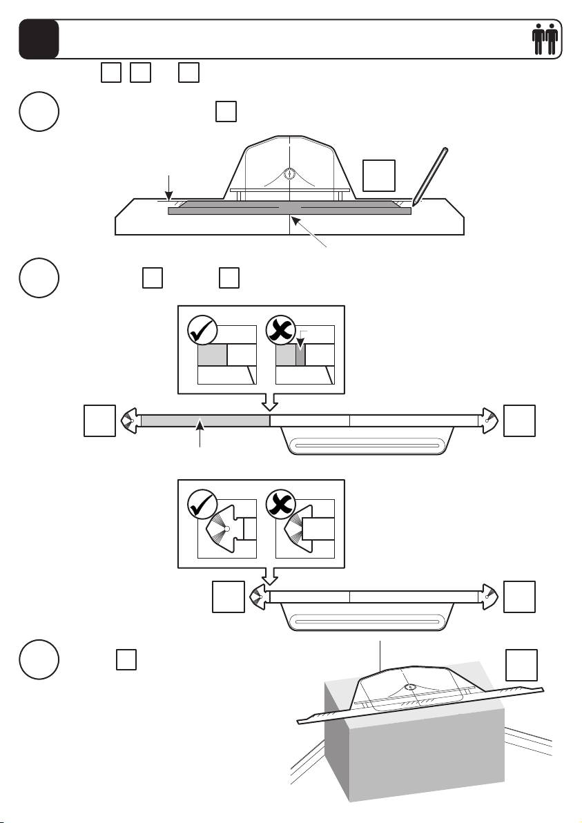
Determine TV and Cornermount Position
3
Use templates , and to help you position your TV and Cornermount accurately.
i
ii
Max Open
PT1 PT3PT2
Put your TV onto template and draw around it, then cut it to shape
Ensure back of TV
is level with line
Put template on top of
PT1 PT2
PT3
PT3
TV
Ensure your TV is central
Red
PT2 PT1
Green represents full range of extension
Max Closed
iii
PT2
Position roughly where you want
to place your TV and Cornermount.
Placing it on top of the giftbox will help
you mark your wall more accurately.
PT3
PT1
PT3
Page 9
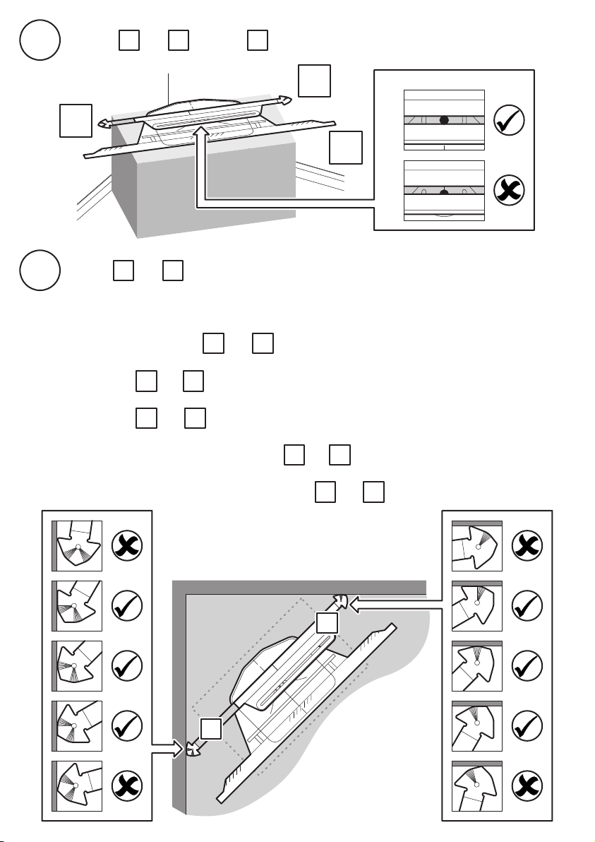
Position and on top of
iv
PT1 PT3PT2
PT1
Ensure hole is inside slot
PT2
PT3
Extend and until they make contact with the wall.
v
Please note: You can only attach your Cornermount to Solid Wall or Wood Stud Wall.
If you are attaching to Wood Stud Wall the location of the wood studs will determine
where you can position and .
If you have and at max extension it is possible you will see some of the Support
Arm Assembly when you view your TV, however, you will have more movement.
If you have and at min extension it is possible you will not see any of the Support
Arm Assembly when you view your TV, however, you will have less movement.
Please consider this when positioning and .
PT1
PT2
PT1 PT2
PT1 PT2
PT1 PT2
PT1 PT2
The diagram below shows how the ends of and must make contact with the wall.
PT2
PT1 PT2
PT1
Page 10
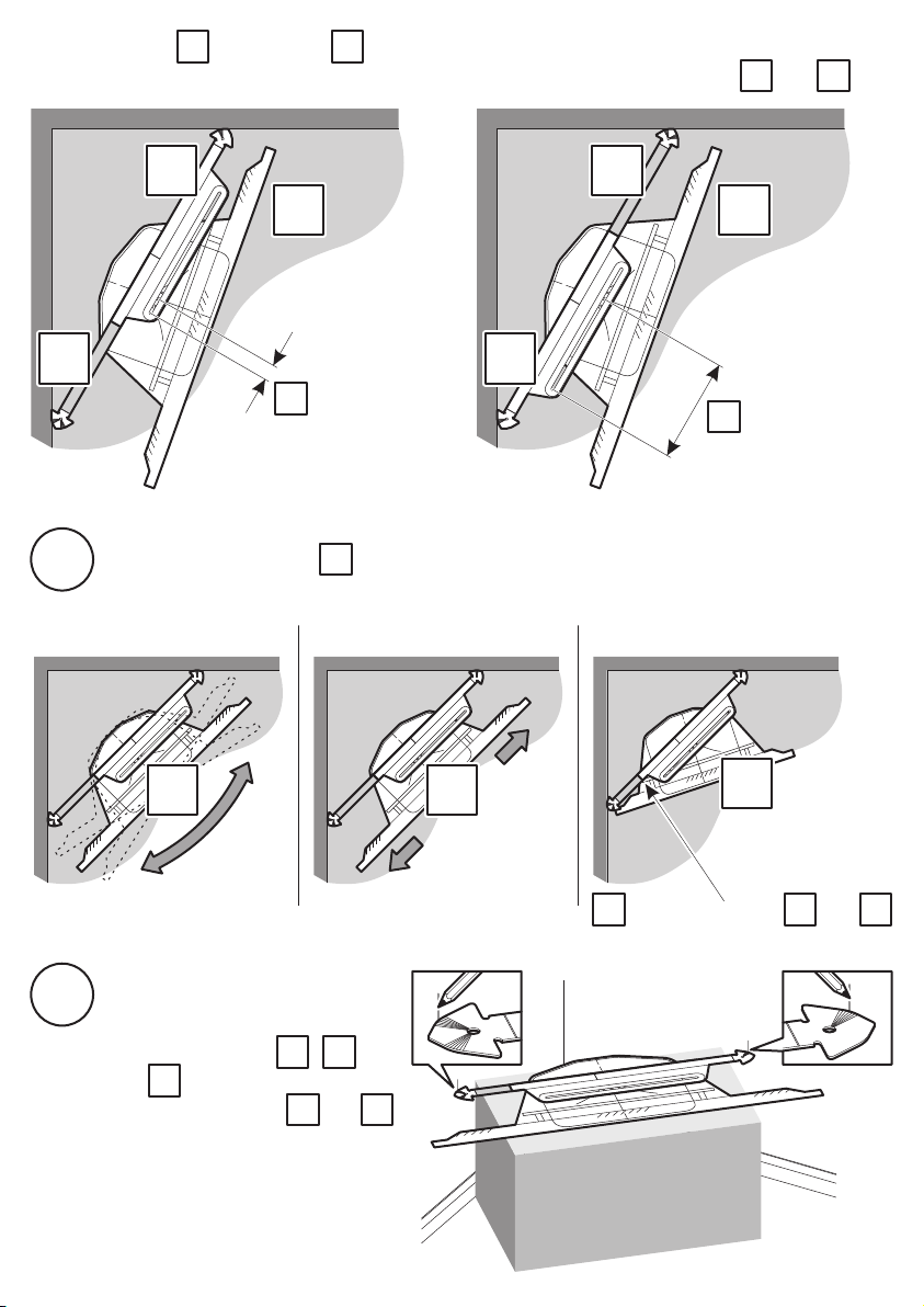
You can turn 180° and flip over so that your TV can move further in another direction.
The example shows how you can get extra movement to the left by swapping and .
PT1PT2
PT1 PT2
PT1
PT3
PT2
has only a
PT3
small amount of
adjustment to
the left
Turn and slide template to see that there are no clashes. Always ensure hole is
vi
inside slot, see step iv.
Turn Slide
PT3
PT3
PT3
PT1
PT2
Clash
PT3
can now
PT3
move further
to the left
PT3
vii
Once you have decided on
the position of your TV and
Cornermount tape ,
and together.
PT3
Mark the wall where and
touch the wall using the lines
as a guide.
PT1 PT2
has clashed with and .
This angle of TV is not possible
PT2PT1
PT1 PT2PT3
Page 11
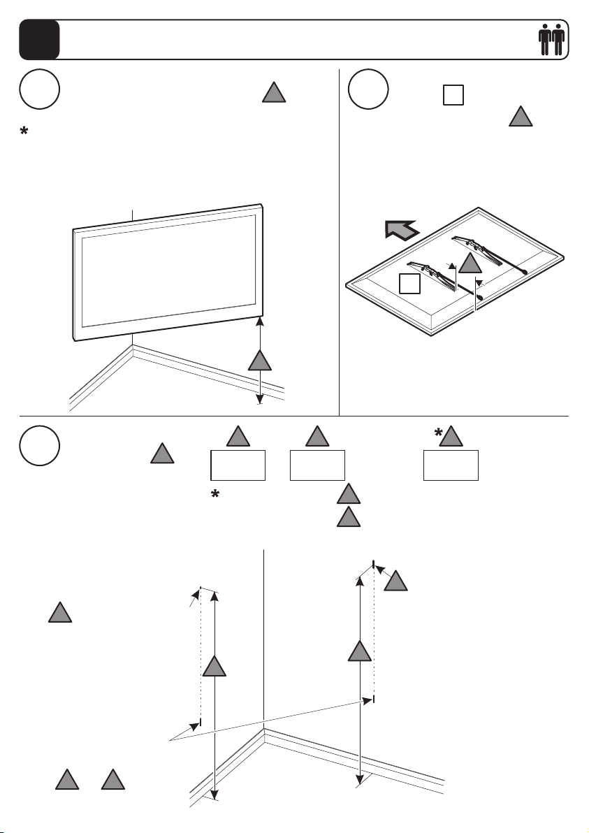
Determine TV and Cornermount Height
4
Decide how high you want the bottom of your
TV to be from the floor (dimension a ).
i ii
If you have purchased, or plan to purchase, an
additional shelf module you will need to take this into
consideration as this will affect how high the bottom of
your TV can be from the floor.
Complete the sum to
iii
get dimension c
c
a
a
Measure from the bottom of
bracket B2 to the bottom of
your TV (dimension b )
Top
B2
364+
+
B2
b
b
cba
=
d is your first drill point
d
Use the marks you made
in step 3 as a guide to
mark and
d e
Minimum dimension c = 1000mm if using a 1 shelf module
Minimum dimension c = 1150mm if using a 2 shelf module
c
c
c
e is a small vertical line
e
c
Page 12
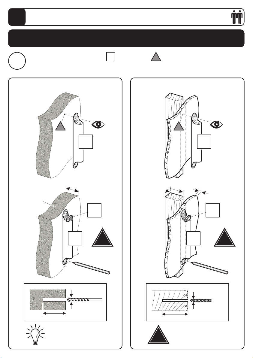
Fitting the Support Arm Assembly
5
Fitting the support arm assembly takes 8 steps. Follow the 8
steps to ensure your support arm assembly is square and level.
Position the top hole of bracket over drill point you made in step 4, and mark the
bottom drill point
i
Solid Wall
d d
H
d
Wood Stud
H H
100mm (4") Min
Concrete
50 x 100mm
(2 x 4") Min
Y
12.5mm
(½") Max
Y
H
Take care
Ø12mm
(15/32")
75mm (3")
Remove dust from hole
!
Ensure bracket is in the
centre of the wood stud
!
H
Ø5mm
(3/16")
75mm (3")
!
Take care
Page 13
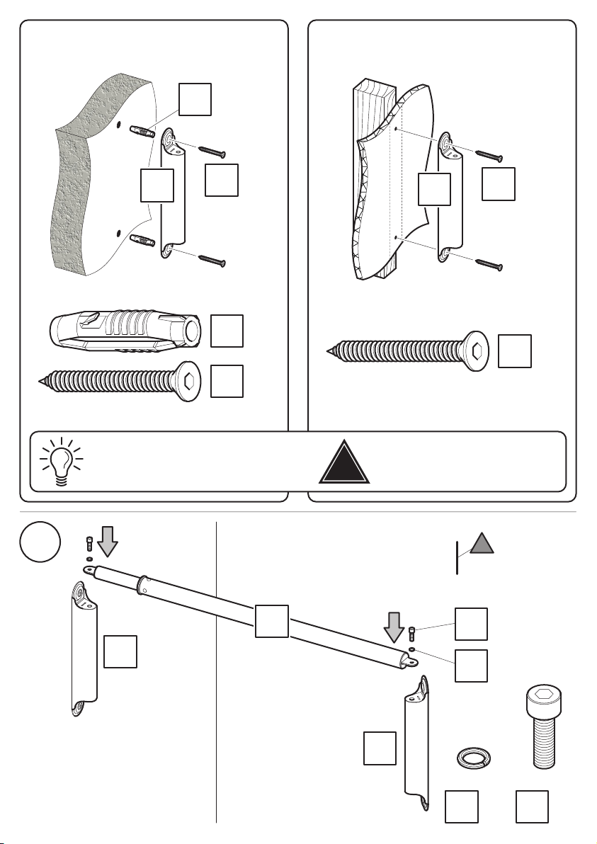
Solid Wall Wood Stud
x2
X1
x2
H
X2
X1
X2
H
x2
x2
X2
X2
x2
x2
ii
Lubricate screw thread with soap
G
H
DO NOT over tighten screws.
Tighten screws by hand only
!
H
O3
e
x2
S
x2
O3
M8 M8
x2
S
x2
Page 14
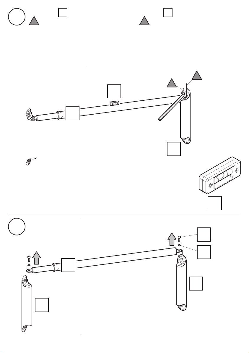
iii
Ensure part is level and align the top hole of bracket with the vertical pencil line
e you made in step 4 Mark this as drill point f
G H
fe
e
f
Y
G
H
iv
H
G
H
S
O3
Y
x1
x2
x2
Page 15
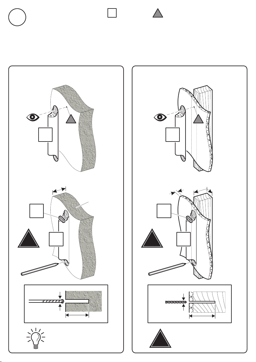
Position the top hole of bracket over drill point f you made in step iii, and mark the
bottom drill point
v
H
f
Solid Wall Wood Stud
f f
H H
100mm (4") Min
Y
!
Take care
H
Ø12mm
(15/32")
75mm (3")
Remove dust from hole
Concrete
12.5mm
(½") Max
!
Take care
50 x 100mm
(2 x 4") Min
Y
H
Ø5mm
(3/16")
75mm (3")
Ensure bracket is in the
centre of the wood stud
!
Page 16
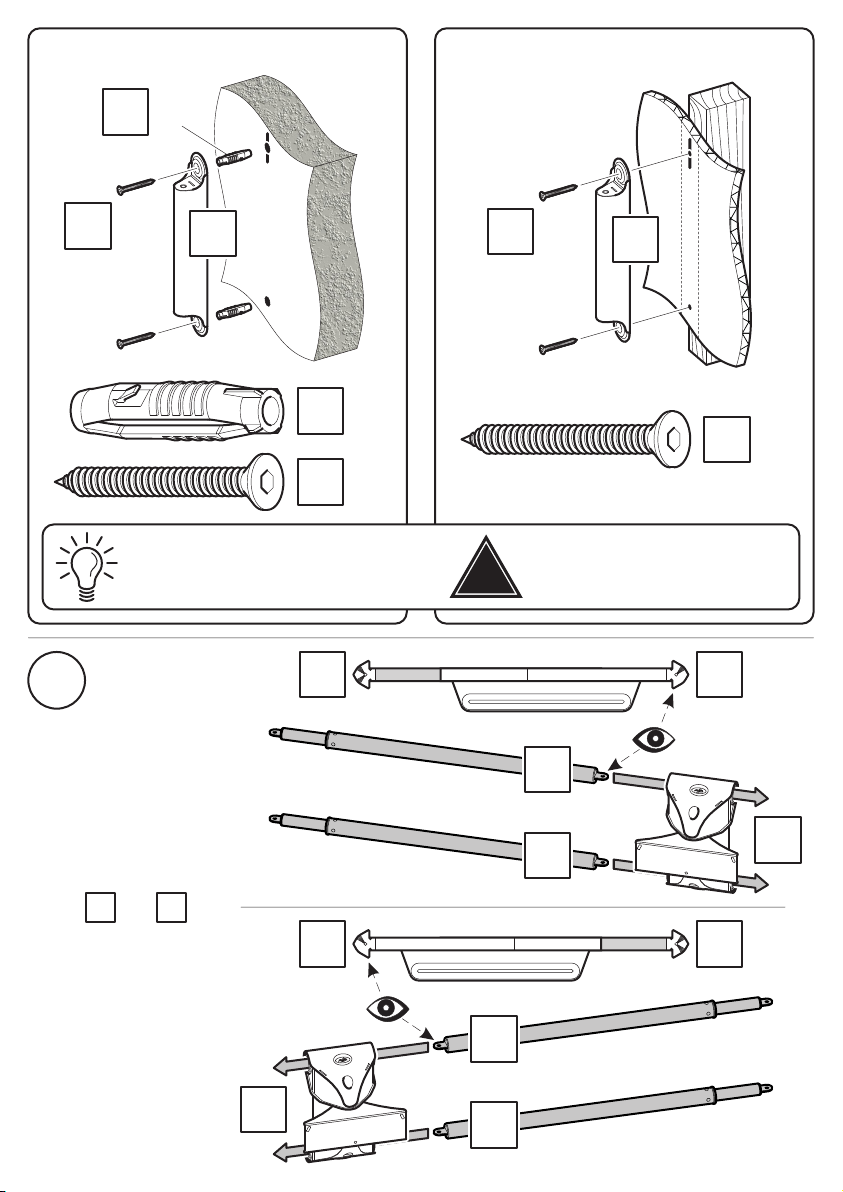
X2
Solid Wall Wood Stud
x2
X1
x2
H
X1
X2
x2
x2
X2
x2
H
X2
x2
Lubricate screw thread with soap
vi
Remember to assemble
G C
parts and in
the correct orientation.
DO NOT over tighten screws.
Tighten screws by hand only
!
PT2 PT1
G
G
G
C
G
C
PT2PT1
Page 17
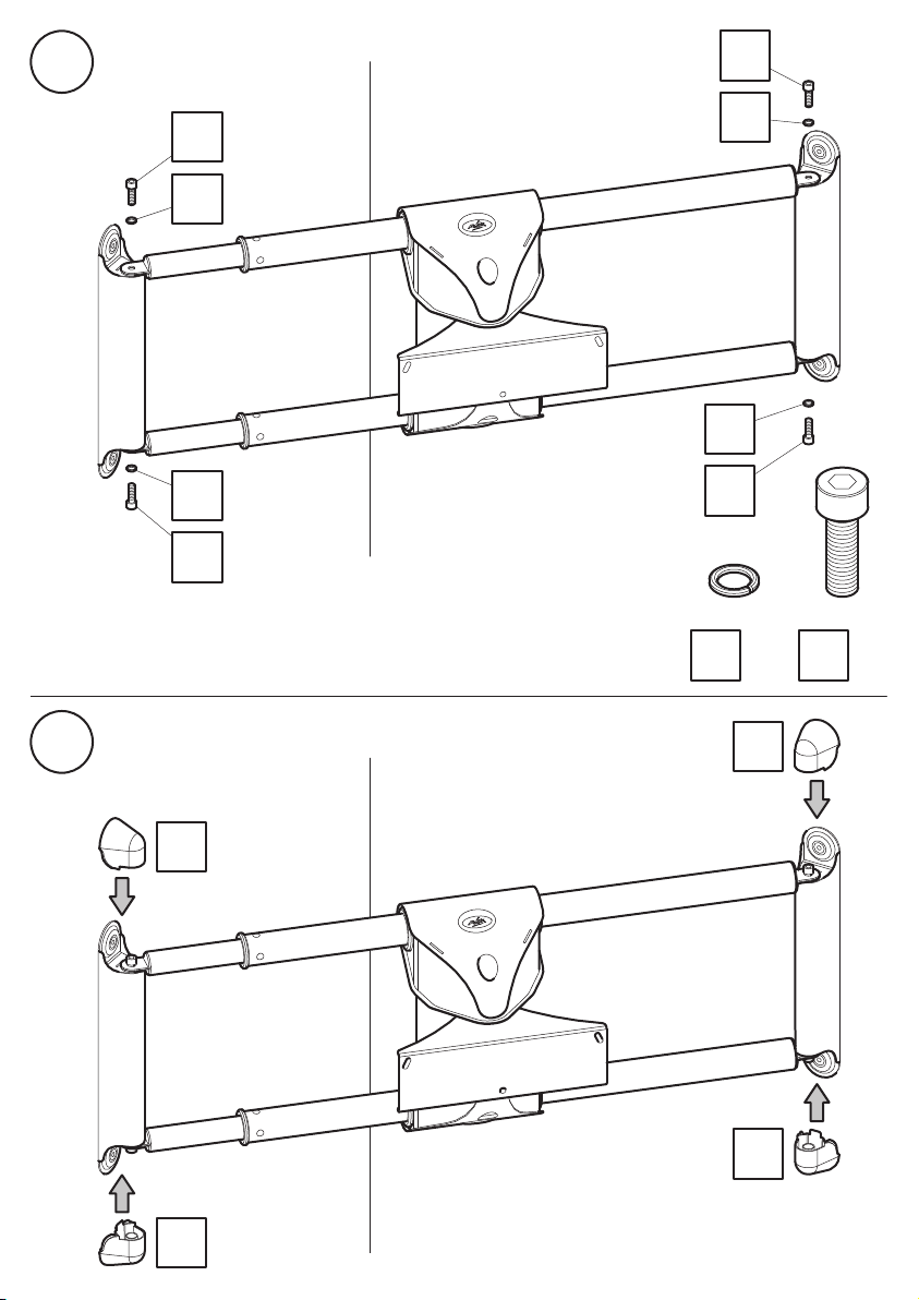
vii
S
viii
S
O3
O3
S
O3
O3
S
M8 M8
x4
O3
L
S
x4
L
L
L
Page 18
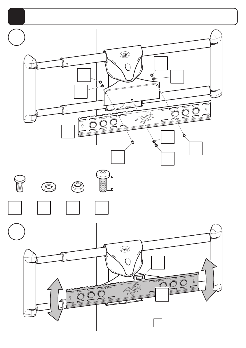
Fitting the TV Bracket
6
i
P1
A
M6 M6 M6
N
x2
O1
x3
P1
ii
P1
O1
x2
M6
Q
x1
N
16mm
O1
O1
N
Q
Y
A
Check bracket A is level before fully tightening
A
Page 19
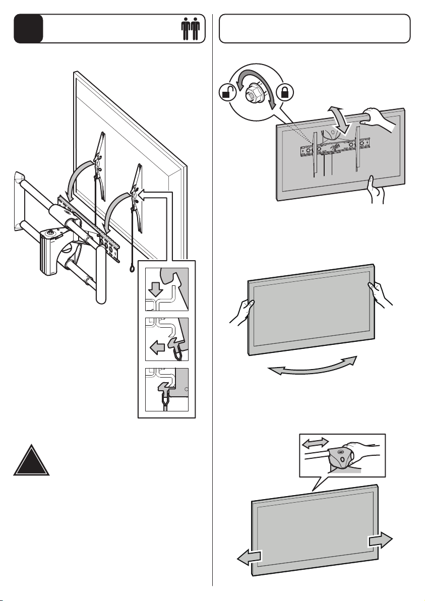
Connecting the TV
7
Optional
Lock Tilt
x4
Turn
Check all fittings are tight
!
Slide
Page 20
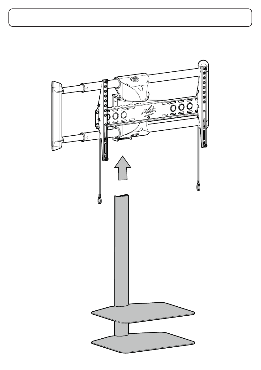
Optional Shelves
You can purchase a separate shelf module which can be built as either 1 or 2 shelves. There will
be detailed installation instructions packaged with the shelf module.
 Loading...