

Page 1
CONFIDENTIAL
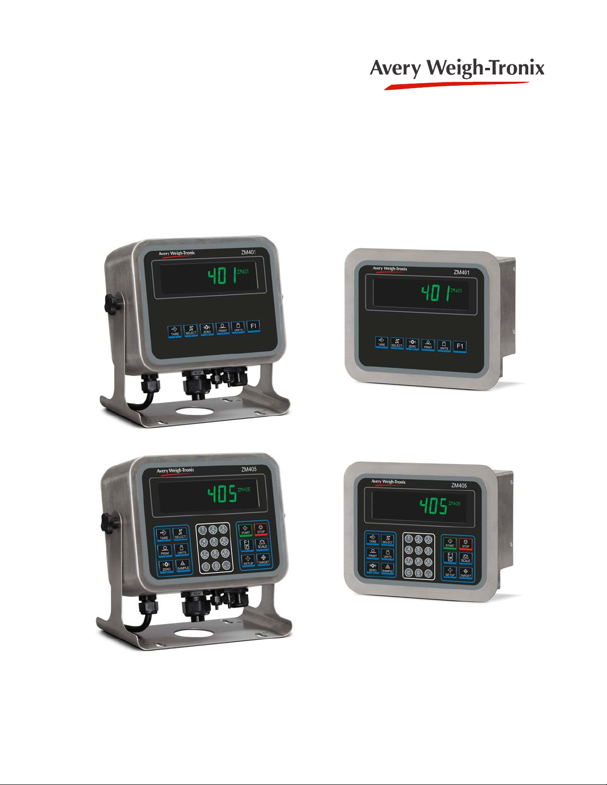
ZM401/405
Weight Indicators
Service Manual
original instructions
AWT35-501334
Issue AA
Page 2

Avery Weigh-Tronix is a trademark of the Illinois Tool Works group of companies whose ultimate parent company is
Illinois Tool Works Inc (“Illinois Tool Works”). Copyright © 2015 Illinois Tool Works. All rights reserved.
No part of this publication may be reproduced by making a facsimile copy, by the making of a copy in three dimensions of a two-dimensional
work and the making of a copy in two dimensions of a three-dimensional work, stored in any medium by electronic means, or transmitted in
any form or by any means, including electronic, mechanical, broadcasting, recording or otherwise without the prior written consent of the
copyright owner, under license, or as permitted by law.
This publication was correct at the time of going to print, however Avery Weigh-Tronix reserves the right to alter without notice the
specification, design, price or conditions of supply of any product or service at any time.
ZM401_405_s_en_501334.book
Page 3

Table of Contents
page
Manual revision history .............................................................................................................................7
Chapter 1 General information and warnings ............................................................. ............................ 9
About this manual ..............................................................................................................9
Text conventions .........................................................................................................9
Special messages .......................................................................................................9
Installation ....................................... .................................... ................................ .............10
Torque specifications ................................................................................................10
Proper grounding of cables .......................................................................................10
Panel mount scale interface cable installation ..........................................................11
Safe handling of equipment with batteries ................................................................12
Wet conditions ...........................................................................................................12
Routine maintenance .......................................................................................................12
Cleaning the machine ......................................................................................................13
Training ..................................... ............................................................. ..........................13
Sharp objects ........ .... ... ... ... .... ...................................... .... ... ... ... ... .... ................................13
FCC and EMC declarations of compliance ......................................................................13
Chapter 2 Introduction ............................................................................................................................ 14
Front panel .......................................................................................................................14
Front Display .............................................................................................................16
Powering up the ZM400 ...................................................................................................17
Alphanumeric entry procedure (ZM401 only) ...................................................................17
Using the alphanumeric keypad (ZM405 only) ................................................................18
Entering negative numbers or decimal point ....................................................................18
String index/character data entry .....................................................................................18
Chapter 3 Introduction to the menus ........................................................... ..........................................20
Accessing the menus .......................................................................................................21
Exiting the menus ............................................................................................................21
Menu annunciators ......... ... .... ... ....................................... ... ... ... ... .... ... .............................22
Quick Code parameter entry ............................................................................................23
Chapter 4 User level menus ............................................. ....................... ...................... ....................... ...24
User menu ......... ... .... ...................................... .... ... ... ... .... ... ...................................... .... ...24
Time ..........................................................................................................................25
Date ....................................... .................................................... ................................25
Site ID ........................................................................................................................26
Seal ...........................................................................................................................26
About menu ......................................................................................................................27
Boot (Bootloader) ......................................................................................................28
Firmware ...................................................................................................................28
App ............................................................................................................................28
Serial .........................................................................................................................28
Option ....................................... .................................................... ............................. 29
Enet ...........................................................................................................................29
Download ..................................................................................................................30
BSQ .................................... ................................................... .................................... 30
Audit menu ...... ....................................... ... ... ... .... ... ... ....................................... ... ... ... .......31
Counter ..................................... ....................... ................... ....................... ................31
Print ...........................................................................................................................32
ZM400 Series Indicators Service Manual 3
Page 4

Chapter 5 Diagnostics level menus .................................................... ................................................... 33
Diag menu ...................... .... ... ....................................... ... ... ... .... ... ... ................................ 33
Scale ......................................................................................................................... 34
Current Zero ............................................................................................................. 34
Display ...................................................................................................................... 35
Buttons ............................... .................................................................... ...................35
Ports ................................ ....................................... ...................................... .............35
Inputs ........................................................................................................................ 36
Outputs ...................................... ......... ....... ......... .......... .......... ......... .......... .......... ...... 36
Options ...................................... ...................................... ....................................... ... 37
Logs .......................................................................................................................... 37
BSQ ................................. .......... ...... .......... ......... .......... .......... ......... .......... .......... ...... 38
Chapter 6 ADMIN level menus ...................................... ............. ............. ............. ............. ............. ......... 39
Setup menu .....................................................................................................................39
Calibration Procedure ...................................................................................................... 40
Scale 1-2 ..... .... ... ... ... .... ... ... ....................................... ... ... .... ... ... ... ............................. 40
Zero Procedure .................................. ... .... ... ....................................... ... ... ... .... ... ... ... 41
Span Procedure ........................................................................................................ 42
Linearity Procedure ...... ... ... ... .... ... ... ... ....................................... ... ... .... ... ... ... ............. 42
Input procedure ......................................................................................................... 43
Gravity Factor Procedure .......................................................................................... 44
Display ...................................................................................................................... 45
Calibration Unit .......................................................................................................... 45
Print calibration report ..... ... ... .... ... ... ....................................... ... ... ... .... ... ... ................ 45
Scale ...................................... ...................... .................... ...................... .......................... 46
Scale 1-2 ..... .... ... ... ... .... ... ... ....................................... ... ... .... ... ... ... ............................. 47
Capacity .................................................................................................................... 47
Division ............................... .......... ......... .......... .......... .......... ......... .......... .......... ...... ... 47
Units ...................................... ....................................................................... .............48
Stable .................................... .................................................................... ................ 49
AZT ........................................................................................................................... 49
Filter ..........................................................................................................................50
Ranges ...................................... ...................................... ....................................... ... 51
2,3,Range .............................. .......... ...... .......... .......... .......... ......... .......... .......... ......... 52
Type .......................................................................................................................... 53
System ................................ ...................... ....................... ...................... .......................... 54
Default Values ........................................................................................................... 55
Site ..................................... .................................................................... ...................56
Display ...................................................................................................................... 56
Buttons ............................... .................................................................... ...................57
Display values ........................................................................................................... 57
Tare .................................... .......................................... .......................................... ...60
Config ................................. ....................................... ....................................... ......... 60
Archive ...................................................................................................................... 61
Serial ..................................... .................................................................... ................62
Update ....................................... ......... ....... ......... .......... .......... ......... .......... .......... ...... 62
Password .................................................................................................................. 63
Z-Lock ....................................................................................................................... 63
Beeper ....................................... ......... ....... ......... .......... .......... ......... .......... .......... ...... 63
Number of Scales ............................ ....................................... ... ... ... .... ... ... ................ 64
Ports ................................................................................................................................ 65
Serial ..................................... .................................................................... ................66
Ethernet ................................. ....... ... ...... ....... ...... ....... ...... ....... ...... ... ....... ...... ....... ...... 67
Protocol ..................................... ................................................................... .............69
P.F.Edit ..................................................................................................................... 72
PLC ........................................................................................................................... 72
4 ZM400 Series Indicators Service Manual
Page 5

Printer ....................................... ....................................................... ..........................74
File ...................................... ...................... .................... ...................... .......................74
Options ...................................................................................................................... 76
Chapter 7 Communication port protocols ................................................................ .......................... ...79
SMA Protocol ...................................................................................................................79
Level 1 and 2 Commands .............................................. ... ... .... ................................79
Standard Scale Response Message .........................................................................80
Unrecognized Command Response .........................................................................80
About Command Response ......................................................................................80
Scale Information Command Response ............................. .......................... .............81
Avery Weigh-Tronix Extended SMA Commands ............................................... .... ... 82
ENQ & B-Cast commands ...............................................................................................84
NCI commands ................................................................................................................85
R-Disp commands ...........................................................................................................86
PLC Configuration information .........................................................................................87
ModBus/TCP ............................................................................................................. 87
Ethernet/IP Implicit Messaging: ....................... ... ... .... ... ... ... ... .... ... ... ....... ... ... ... ... .... ... 89
Ethernet/IP Explicit Messaging: .................... ... ... ... .... ... ... ... ... .... ... ...... .... ... ... ... ... .... ... 89
Chapter 8 Option cards ........................................................................................................................... 90
Analog output card .......... ....................................... ... ... .... ... ... ... .......................................91
Current Loop/RS485/RS422 card .......... ... ... ... .................................................................92
USB Device option card ...................................................................................................93
Wireless Ethernet communication (802.11g) card ....... .... ... ... ... ... .... ... ... ... .... ...... ... ... .... ... 94
Internal 120 VAC relay card (for IP69K only) ...................................................................95
Specifications ............................................................................................................ 95
Installing the option card ...........................................................................................96
2nd Scale Input 5VDC Excitation card .............................................................................97
2nd Scale Input 10 VDC Excitation w/STVS card .................. ................................... .......98
External I/O Interface card ...............................................................................................99
AC input, 4 Inputs (120-240VAC) card ..........................................................................100
DC input, 4 inputs(4-30VDC) card .................................................................................101
AC output, 4 relays (20-240VAC) card ..........................................................................102
DC output, 4 relays (3-60VDC) card ......................... ..................................................... 103
Chapter 9 Printed reports .....................................................................................................................104
Configuration report .......................................................................................................104
Calibration report ...........................................................................................................104
Audit report ........... .... ... ... ....................................... ... ... .... ... ... ... .....................................105
Chapter 10 Print formatting .................................................................................................................. 106
Print Format Editor .... ...................................... .... ... ... ... .... ... ...................................... .... .106
Editing an existing print string ........................................................................................107
Inserting characters .................................................................................................108
Deleting characters .................................................................................................109
Inserting tokens, etc. ......................................................................................................111
Other scale tokens .........................................................................................................113
Transmitting leading zeroes ... ... ....................................... ... ... ... ... .... ... ...........................114
Print format errors ........... ... .... ... ... ... ... .... ...................................... .... ... ... ... .... ... ..............115
Chapter 11 Print tokens, parameters and default print formats ... ............................. ........................117
Notes on width syntax ....................................................................................................117
Explanation of width syntax for WEIGHT (integers) ................................................117
Explanation of width syntax for WEIGHT (strings) ..................................................117
Explanation of width syntax for UNITS OF MEASURE (strings) .............................117
Firmware tokens ............................................................................................................118
Additional token tables ............................. .... ... ... ... .... ... ... ... ... ....... ... ... .... ... ... ... ... .... .124
ZM400 Series Indicators Service Manual 5
Page 6

Network tokens .............................................................................................................. 125
ASCII characters ........................................................................................................... 127
Control codes ................................................................................................................ 128
Default print formats ...................................................................................................... 129
Chapter 12 Complete menu structures ............................................................................................... 131
Chapter 13 Technical illustrations ...................................................... ................................................. 137
Stainless steel enclosure assembly ............................................................................... 137
Stainless steel enclosure parts kits ............................................................................... 138
Panel mount enclosure parts and assembly .................................................................. 139
Panel mount enclosure parts lists .................................................................................. 140
System block diagram ................. .... ... ... ....................................... ... ... ... .... ... ... .............. 1 41
ZM umper and switch settings ....................................................................................... 142
ZM remote inputs and outputs, Opto-22 module ........................................................... 143
STVS (Severe Transient Voltage Suppressor) installation ............................................ 144
Outline dimensions (stainless steel) .............................................................................. 145
Outline dimensions (panel mount) ................................................................................. 146
Panel mount assembly .................................................................................................. 147
D-cell Battery pack option (AWT05-505852) and external battery circuitry ................... 148
Keypad overlay replacement procedure ........................................................................ 149
To change the keypad you will need these tools: ................................................... 149
Process to remove and replace the keypad overlay ............................................... 149
Index ....................................................................................................................................................... 151
6 ZM400 Series Indicators Service Manual
Page 7

Manual revision history
Current
Issue
AA Sept. 2015 New manual
AB Sept. 2015 Changed file name and title.
Date Created Details of Changes
ZM400 Series Indicators Service Manual 7
Page 8

8 ZM400 Series Indicators Service Manual
Page 9

1 General information and warnings
1.1 About this manual
This manual is divided into chapters by the chapter number and the large text at the top
of a page. Subsections are labeled using the 1.1 and 1.1.1 convention. The names of
the chapter and the next subsection level appear at the top of alternating p ages of the
manual to remind you of where you are in the manual. The manual name and page
numbers appear at the bottom of the pages.
1.1.1 Text conventions
Key names are shown in bold and reflect the case of the key being described. If a key
has dual functions, the function is shown first followed by the key name in p arentheses
and in bold, such as in these examples: F1, SELECT, PRINT, etc.
Displayed messages appear in bold italic type and reflect the case of the displayed
message.
1.1 About this manual
1.1.2 Special messages
Examples of special messages you will see in this manual are defined below. The
heading words have specific meanings to alert you to additional information or the
relative level of hazard.
ELECTRICAL WARNING!
THIS IS AN ELECTRICAL WARNING SYMBOL.
ELECTRICAL WARNINGS MEAN THAT FAILURE TO FOLLOW
SPECIFIC PRACTICES OR PROCEDURES MAY RESULT IN
ELECTROCUTION, ARC BURNS, EXPLOSIONS OR OTHER HAZARDS
THAT MAY CAUSE INJURY OR DEATH.
WARNING!
This is a Warning symbol.
Warnings mean that failure to follow specific practices and procedures may
have major consequences such as injury or death.
CAUTION!
This is a Caution symbol.
Cautions give information about procedures that, if not observed, could result
in damage to equipment or corruption to and loss of data.
NOTE: This is a Note symbol. Notes give additional and important information, hints
and tips that help you to use your product.
ZM400 Series Indicators Service Manual 9
Page 10
1 General information and warnings
1
2
3
4
5
6
7
89
10
11
12
13
14
Indicator back
plate
1.2 Installation
NO USER SERVICEABLE PARTS. REFER TO QUALIFIED SERVICE
PERSONNEL FOR SERVICE.
1.2.1 Torque specifications
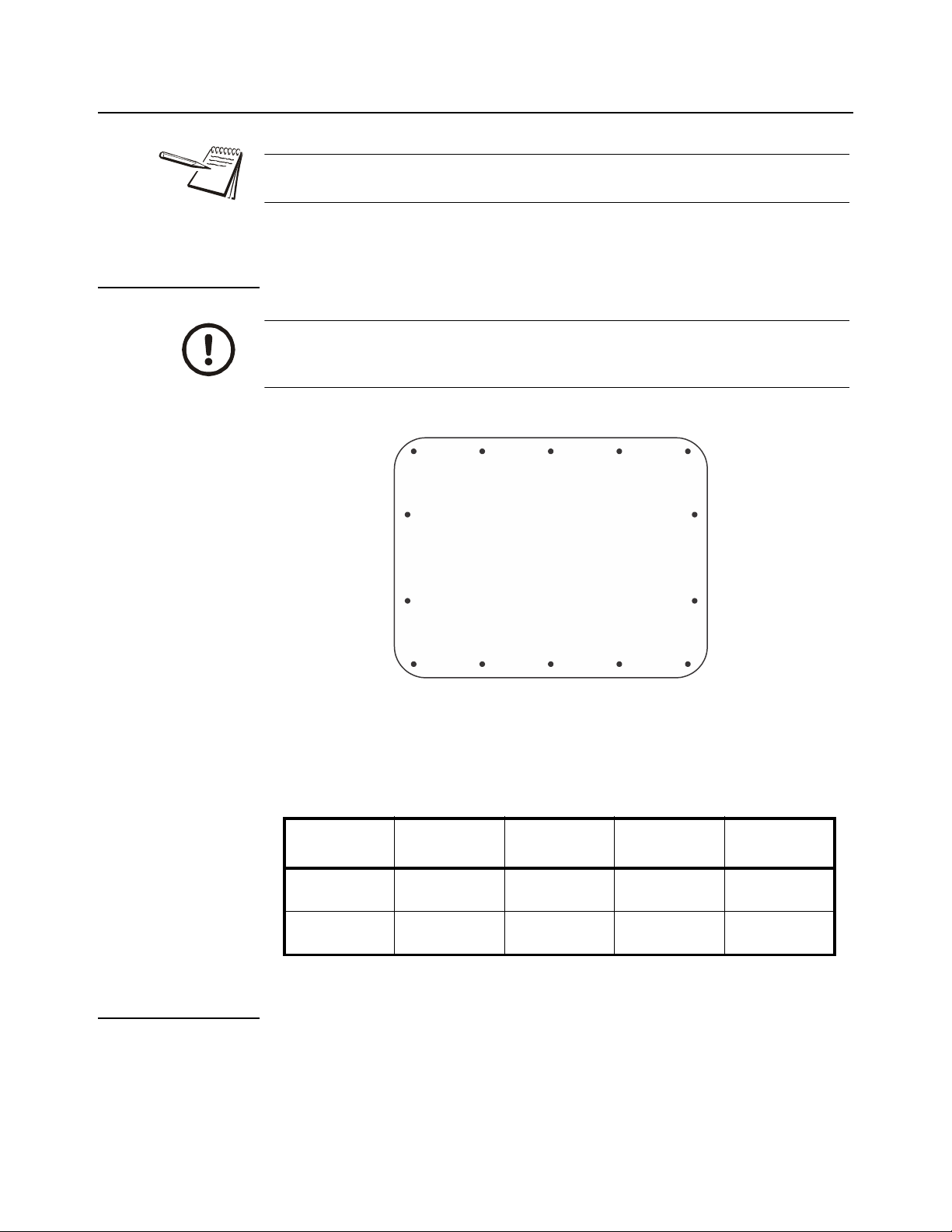
CAUTION: The acorn nuts holding the back plate of the indicator in place must
each be tightened, in multiple passes, in the following pattern to a final torque
of 0.68 N-m (approximately 6 in-lbs) to ensure proper gasket sealing.
There are four sizes of strain reliefs exiting the indicator: PG11, PG7, PG13.5 and NPT
3/4”. The torque specifications for the locknuts which hold the strain reliefs to the
indicator housing and the specs for the dome nuts which seal the cable that passes
through the strain relief are shown in the table below.
3/4” NPT
Strain Relief
Dome Nut
Lock Nut
66.4 lb-in
7.5 N-m
44.2 lb-in
5 N-m
PG13.5 Strain
Relief
33.2 lb-in
3.75 N-m
22.1 lb-in
2.5 N-m
PG11 Strain
Relief
33.2 lb-in
3.75 N-m
22.1 lb-in
2.5 N-m
PG7 Strain
Relief
22.1 lb-in
2.5 N-m
14.4 lb-in
1.62 N-m
1.2.2 Proper grounding of cables
On the stainless steel desktop models, cable shield wires should be grounded directly
to the studs provided at the bottom of the enclosure, close to the strain relief entr y point,
with wire lengths at a minimum. On the aluminum and panel mount models the shield
wires should be connected to the SHLD connection on the corresponding terminal
block connectors.
10 ZM400 Series Indicators Service Manual
Page 11
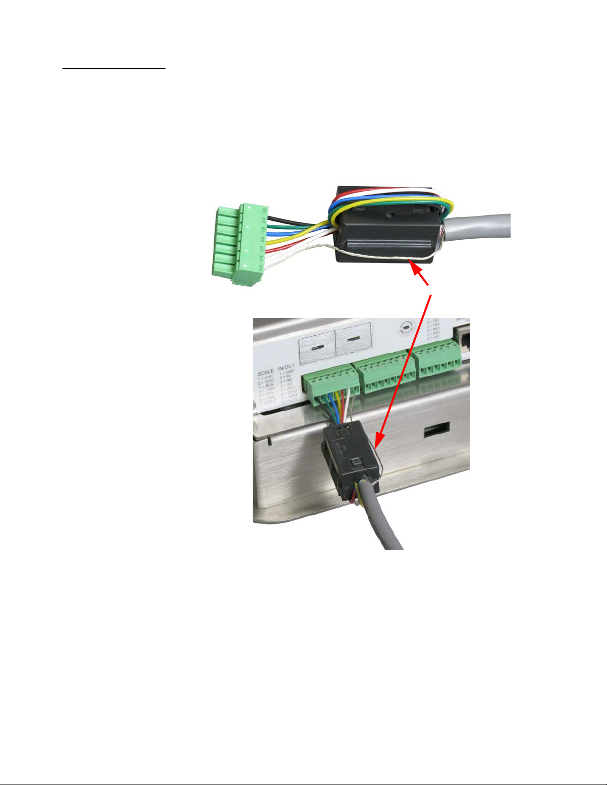
1.2.3 Panel mount scale interface cable installation
Shield drain wire
The ZM401 & ZM405 Panel Mount assemblies include the AWT25-501388 Ferrite.
Installing the Ferrite on the Scale Interface Cable on the Panel Mount models assists
with eliminating potential noise captured by the scale interface cable.
Attach the ferrite onto the scale interface cable by wrapping the unsh ielded wires once
around the ferrite as shown below. Leave the Shield drain wire outside the ferrite and
connect to the SHLD connection on the termina l block, as shown in the photos below.
1.2 Installation
The optional 2nd Scale Input 5VDC & 10VDC Excitation Modules also include the
AWT25-501388 Ferrite for use on the ZM401 & ZM405 Panel Mount Models. The
Ferrites are not needed on the stainless steel desktop models as the Shield of the
Scale Interface cable terminates directly to the studs on the bottom of the enclosure.
ZM400 Series Indicators Service Manual 11
Page 12

1 General information and warnings
1.2.4 Safe handling of equipment with batteries
CAUTION: Danger of explosion if battery is incorrectly replaced. Replace only
with the same or equivalent type recommended by the manufactu r er. Dispose
of used batteries according to the manufacturer’s instructions.
ATTENTION: Il y a danger d'explosion s'il y a remplacement incorrect de la
batterie, remplacer uniquement avec une batterie du même type ou d'un type
équivalent recommandé par le constructeur. Mettre au rebut les batteries
usagées conformément aux instructions du fabricant.
1.2.5 Wet conditions
Under wet conditions, the plug must be connected to the final branch circuit via an
appropriate socket / receptacle designed for washdown use.
Installations within the USA should use a cover that meets NEMA 3R specifications
as required by the National Electrical Code under section 410-57. This allows the unit
to be plugged in with a rain tight cover fitted over the plug.
Installations within Europe must use a socket which provides a minimum of IP56
protection to the plug / cable assembly. Care must be taken to make sure that the
degree of protection provided by the socket is suitable for the environment.
1.3 Routine maintenance
IMPORTANT: This equipment must be routinely checked for proper operatio n
and calibration.
Application and usage will determine the frequency of calibration required for
safe operation.
Always turn off the machine and isolate from the power supply before starting any
routine maintenance to avoid the possibility of electric shock.
12 ZM400 Series Indicators Service Manual
Page 13

1.4 Cleaning the machine
Table 1.1 Cleaning DOs and DON’Ts
DO DO NOT
1.4 Cleaning the machine
Wipe down the outside of standard products
with a clean cloth, moistened with water and
a small amount of mild detergent
Spray the cloth when using a proprietary
cleaning fluid
Attempt to clean the inside of the machine
Use harsh abrasives, solvents, scouring cleaners or
alkaline cleaning solutions
Spray any liquid directly on to the display windows
1.5 Training
Do not attempt to operate or complete any procedure on a machine unless you have
received the appropriate training or read the instruction books.
T o avoid the ri sk of RSI (Repetitive S train Injury), place the machine on a surface which
is ergonomically satisfactory to the user. T ake frequent br eaks during prolonged usage.
1.6 Sharp objects
Do not use sharp objects such as screwdrivers to operate the keys.
1.7 FCC and EMC declarations of compliance
United States
This equipment has been tested and found to comply with the limits for a Class A digital device, pursuant to Part 15 of the FCC Rules.
These limits are designed to provide reasonable protection against harmful interference when the equipment is operated in a
commercial environment. This equipment generates, uses, and can radiate radio frequency energy and, if not installed and used in
accordance with the instruction manual, may cause harmful interference to radio communications. Operation of this equipment in a
residential area is likely to cause harmful interference in which case the user will be required to correct the interference at his own
expense.
Canada
This digital apparatus does not exceed the Class A limits for radio noise emissions from digital apparatus set out in the Radio
Interference Regulations of the Canadian Department of Communications.
Le présent appareil numérique n’émet pas de bruits radioélectriques dépassant les limites applicables aux appareils numériques de
la Classe A prescrites dans le Règlement sur le brouillage radioélectrique edicté par le ministère des Communications du Canada.
European Countries
WARNING: This is a Class A product. In a domestic environment, this product may cause radio interference in which the user may be
required to take adequate measures.
ZM400 Series Indicators Service Manual 13
Page 14
2 Introduction
This manual covers the installation, connections, configuration and servicing of the
ZM400 series indicators, shown in Figure 2.1. The ZM401 and ZM405 come in
stainless steel panel mount and desktop models. The ZM400 indicator will support up
to two scales with a maximum total of 16 x 350 ohm l oad cells. Th e st anda rd indi cator
can connect to a single analog scale, an analog and digit al scale o r two digit al scales.
With an option card they can support 2 analog scale inputs. The standard indicator
connectivity includes a USB Host, two RS232 ports and an Ethernet port. The following
internal module cards are available as options:
l Analog Output
l Current Loop/RS485/RS422
l USB Device
l Wireless 802.11g
l Internal 120 VAC relay
l 2nd Scale Input 5VDC Excitation
l 2nd Scale Input 10 VDC Excitation
l External I/O Interface (for existing GSE or 1310 I/O cards)
l AC input, 4 Inputs (120-240VAC)
l DC input, 4 inputs (4-30VDC)
l AC output, 4 relays (20-240VAC)
l DC output, 4 relays (3-60VDC)
The indicators also have three logic level inputs with configurable functions and thre e
set point outputs and can interface with remote analog or digital scales, PLC's and
scoreboards. See the Specification literature for a full list of specifications.
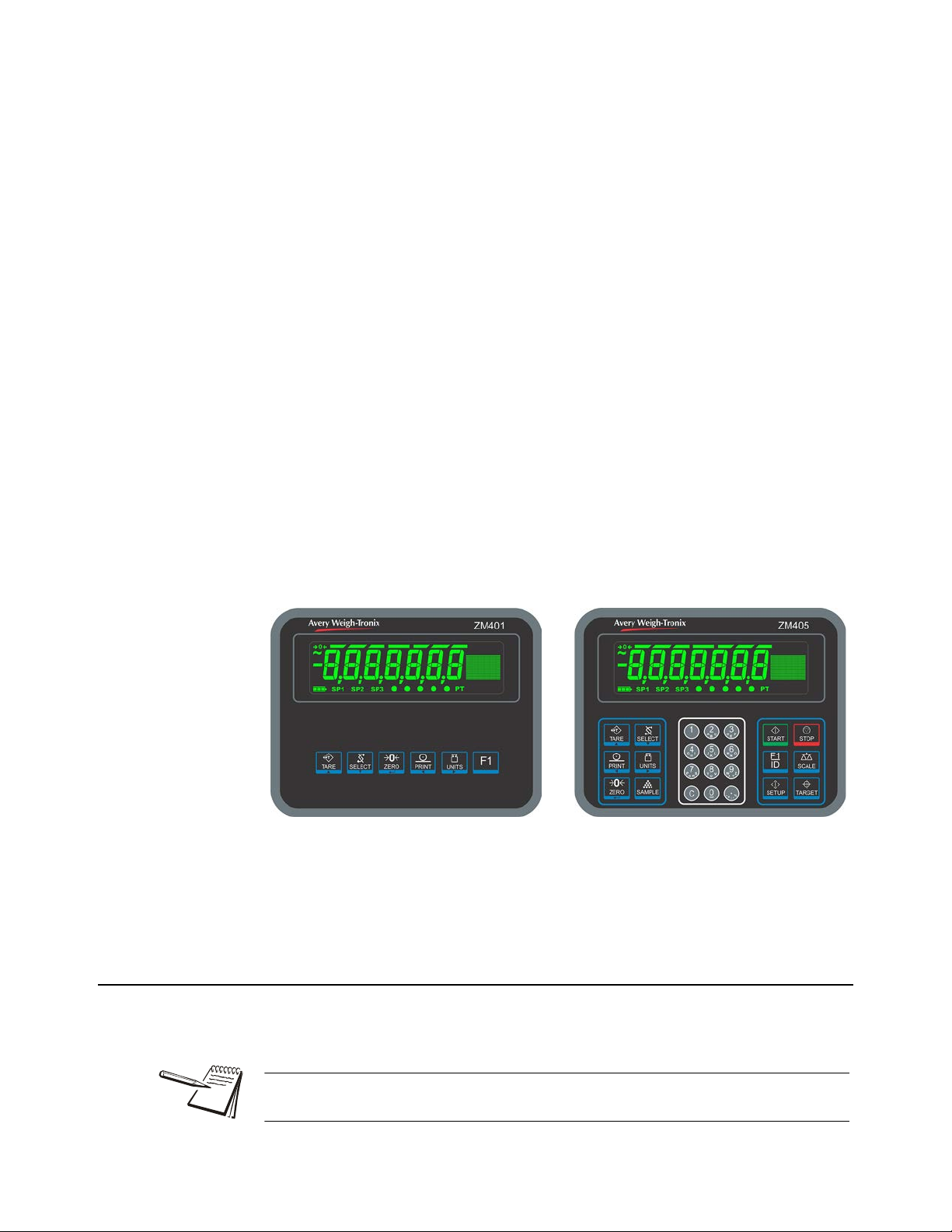
Figure 2.1 Front panels of the ZM401 and ZM405 indicators
The ZM400 can connect to USB flash drives, printers, remote displays, co mputers and
other peripheral devices.
2.1 Front panel
The front panels for the ZM400 series are shown in Figure 2.1 and consists of the keys
and the display.
Never press a key with anything but your finger. Damage to the overlay may result if
sharp or rough objects are used.
ZM400 Series Indicators Service Manual 14
Page 15
2.1 Front panel
TAR E
SELECT
ZERO
PRINT
UNITS
F1
TAR E
SELECT
PRINT
UNITS
ZERO
SAMPLE
START
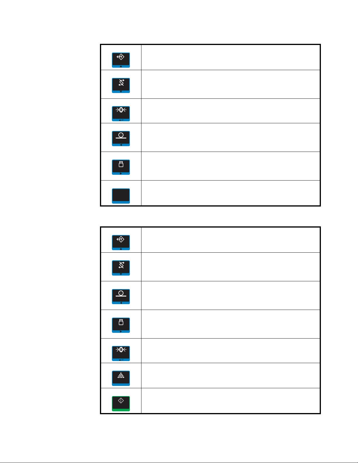
The normal function of the keys on the front panel of the ZM401 are listed below.
Press the TARE key to perform a pushbutton tare function.
Acts as an up arrow key for menu navigation.
Allows entry of numeric values.
Press the SELECT key to toggle between the active display values.
Press and hold to enter the setpoint editor.
Acts as a down arrow key for menu navigation.
Allows entry of numeric values.
Press the ZERO key to zero the display.
Acts as an ENTER key to accept a displayed value or function.
Press the PRINT key to send information to a peripheral device through a
configured communications port.
Acts as a left arrow key for menu navigation and removes last digit during numeric
entry.
Press the UNITS key to scroll through the available units of measure while in
normal operating mode.
Acts as a right arrow key for menu navigation and inserts new digit during numeric
entry.
Press the F1 key to select application specific choices.
Aborts a numeric entry and acts as an ESCAPE key in the menu navigation.
Press and hold to view the password entry screen for menu access.
The normal function of the keys on the front panel of the ZM405 are listed below.
Press the TAR E key for pushbutton, key entry or preset Tare functions.
Acts as an up arrow key for menu navigation.
Allows entry of numeric values.
Press the SELECT key to toggle between the active display values.
Press and hold to enter the setpoint editor.
Acts as a down arrow key for menu navigation.
Allows entry of numeric values.
Press the PRINT key to send information to a peripheral device through a
configured communications port.
Acts as a left arrow key for menu navigation and removes last digit during numeric
entry.
Press the UNITS key to scroll through the available units of measure while in
normal operating mode.
Acts as a right arrow key for menu navigation and inserts new digit during numeric
entry.
Press the ZERO key to zero the display.
Acts as an ENTER key to accept a displayed value or function.
The SAMPLE key can be used to perform custom application functions.
The START key can be used to perform custom application functions.
ZM400 Series Indicators Service Manual 15
Page 16
2 Introduction
STOP
ID
F1
SCAL E
SETUP
TAR G ET
C
123
456
789
Q
R
PS
X
Y
WZ
BACE
DF
KJLN
MO
H
GI
U
TV
0
:
,
-
%
#
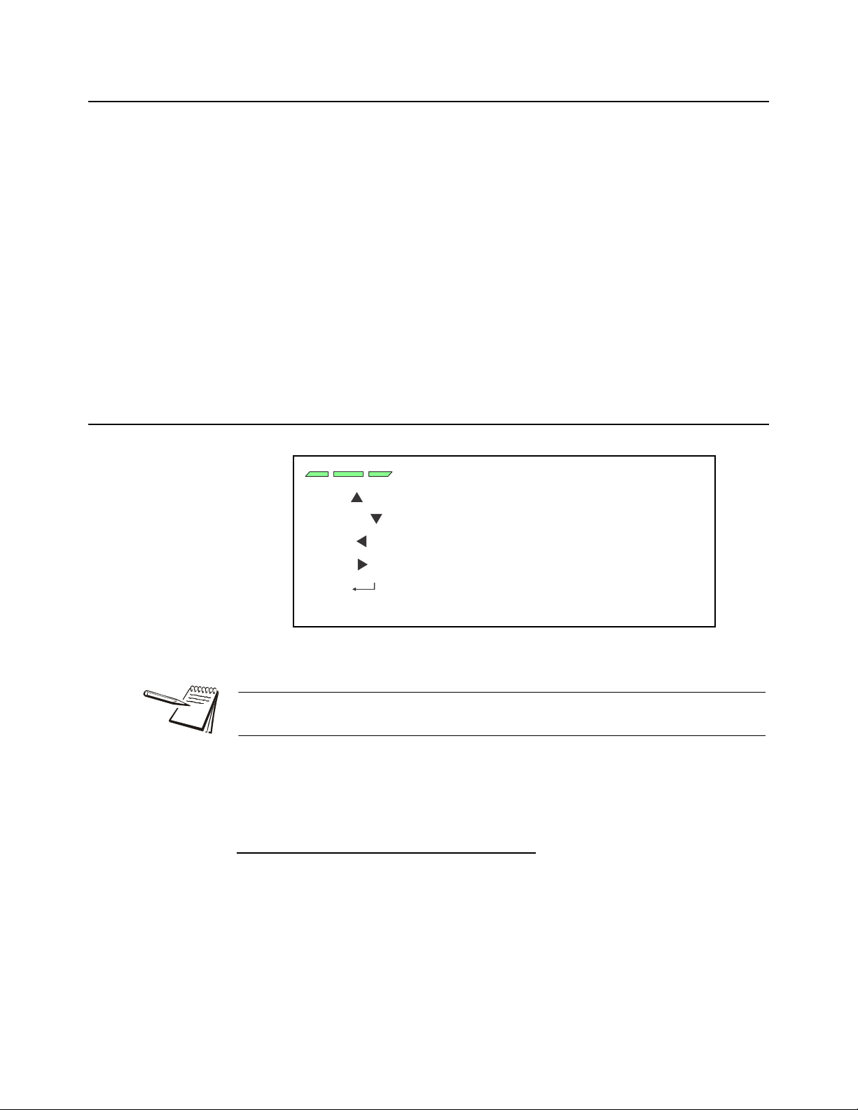
bargraph
center-of-zero
motion
battery status
setpoints
preset
tare
custom
annunciators
Ethernet
activity
graphic
display area
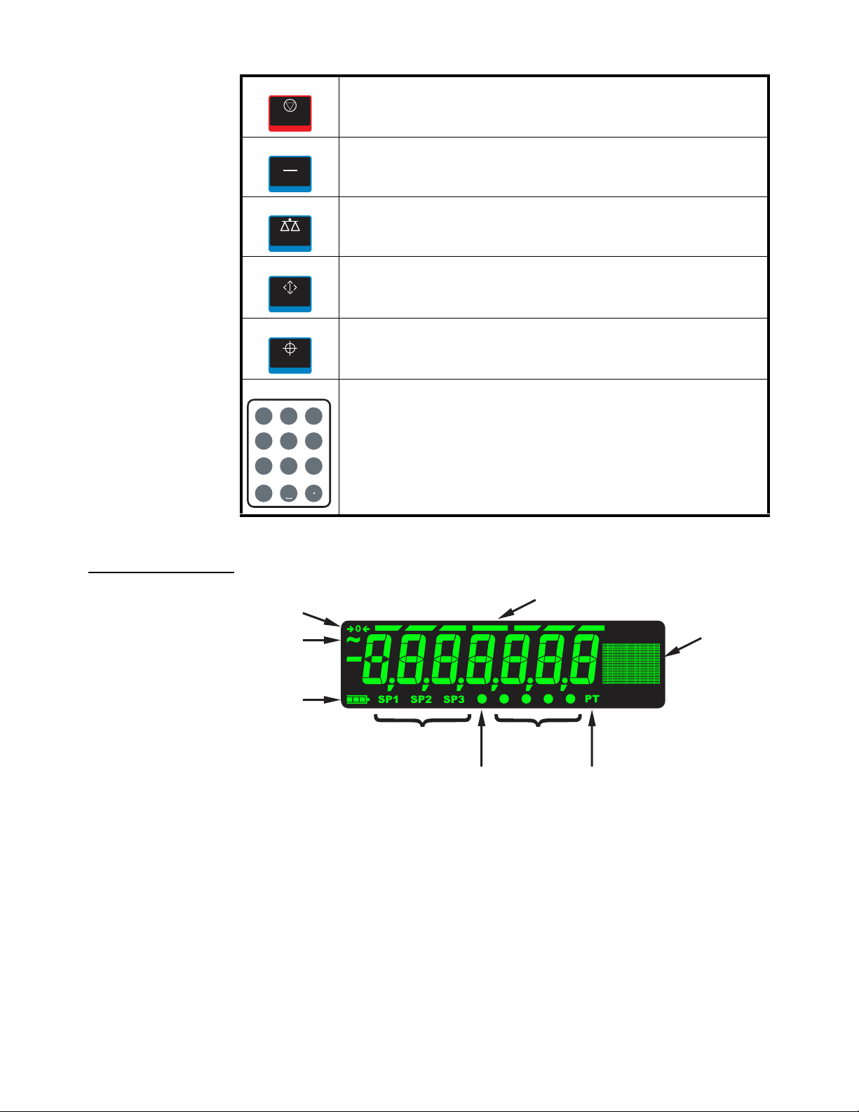
The STOP key can be used to perform custom application functions.
The F1/ID key can be used to perform custom application functions. It can also be
used to abort a numeric entry and it acts as an ESCAPE key in the menu navigation.
The SCALE key can be used to perform custom application functions. It can also be
used to select the active scale when more than one scale is enabled.
The SETUP key can be used to perform custom application functions. It can also be
used to view the password entry screen for menu access.
The TAR GET key can be used to perform custom application functions.
Use the numeric keypad to enter numbers in the appropriate screens.
Press the C (CLEAR) key to clear the last entry.
2.1.1 Front Display
16 ZM400 Series Indicators Service Manual
Page 17
2.2 Powering up the ZM400
These segments flash in alphanumeric entry mode
Press to increment the flashing number
Press to decrement the flashing number
Press to backspace cursor in a number
Press to advance cursor in a number
Press to accept a value
Press to escape an entry screen
TARE /
-
SELECT /
-
PRINT /
-
UNITS /
-
ZERO /
-
F1 /
ESC -
2.2 Powering up the ZM400
The indicator is always active as long as power is received. Power can be supplied by:
l AC power cord connected to a properly grounded outlet (100 V AC - 24 0 V AC,
50 or 60 Hz)
l External 12VDC @ 1.2 Amps up to 36VDC @400mA (14.4 W atts). These are
the power requirements for a fully loaded unit (16 x 350 load cell, 5 00mA out
the 5V COM port terminal block, 500mA load on USB Host, and Wireless
option card installed).
l AC to 24VDC power converter (optional accessory for panel mount version)
l Optional external battery pack with 4 D cells:
1 x 350 ohm load cell = 6 hours battery life
4 x 350 ohm load cell = 4 hours battery life
8 x 350 ohm load cell = 1 hour battery life
(See D-cell Battery pack option (AWT05-505852) and external battery
circuitry on page 148 for more information.)
2.3 Alphanumeric entry procedure (ZM401 only)
The keys in Figure 2.2 have alternate functions in alphanumeric entry screens.
Figure 2.2 Key function during numeric entry
When the graphic display is present you can scroll through numbers, alpha
characters and symbols by repeatedly pressing the TARE or SELECT keys.
Use the keys, as described in Figure 2.2, to enter an alphanumeric value on th e display .
For alphanumeric menu entries the graphics display will only show the last six
characters entered. Following is an example:
Example: To key in ZM4:
Repeatedly press the TARE() or SELECT() key until Z appears on the display.
Press the UNITS() key once to move cursor one space to the right.
Repeatedly press the TARE() or SELECT() key until M appears on the display.
Press the UNITS() key once to move cursor one space to the right.
ZM400 Series Indicators Service Manual 17
Repeatedly press the TARE() or SELECT() key until 4 appears on the display.
Press the ZERO key to enter or accept the value.
Press the PRINT() key to move the entry function one digit to the left. This effectively
deletes the current value in that position and allows you to enter a new value in that
position.
Page 18

2 Introduction
When these segments
are flashing, you are in
the string index select
mode. In this mode you
select the index
character you want to
edit or add/delete a
character.
String Index
number
Character
(ASCII characters
are entered as
decimal values)
2.4 Using the alphanumeric keypad (ZM405 only)
Use the alphanumeric keypad to enter numbers and words when prompted by the
indicator. For alphanumeric menu entries the graphics display will only show the last
six characters entered.
The action is similar to using a cell phone to select the number or letter. A rapid
succession of presses will scroll through the number on the key and then the letters,
starting with upper case and then lower case. The decimal key scrolls through the
negative sign, pound sign, colon, comma and percent sign. The 0 key toggles between
0 and a space.
2.5 Entering negative numbers or decimal point
To enter a minus sign for a negative number or a decimal point (or comma), press the
C key (or PRINT key) to clear the current value from the display.
Then to enter a negative number, with a single 0 displayed press SELECT. The first
character will then change to a (-) negative sign. Enter the rest of the digits normally.
To enter a decimal point (or comma), on a ZM405 use the decimal point key. On a
ZM401 when the flashing digit is a 0 press the SELECT key and a decimal point (or
comma) will appear. Then press the UNITS key to scroll in the next digit to follow the
decimal and enter the rest of the digits normally. To enter a value less than 1 requires
the entry of the leading 0 before a decimal point is allowed.
2.6 String index/character data entry
18 ZM400 Series Indicators Service Manual
Below are guidelines to create or edit text and scale information for print format s. This
is a sample of a string entry display.
Left-flashing bar graph segment s indicate you are in the S tring Index select mode. Use
the Table 1 key legend to:
l move to the index number you want to edit
l add a new index number
Page 19

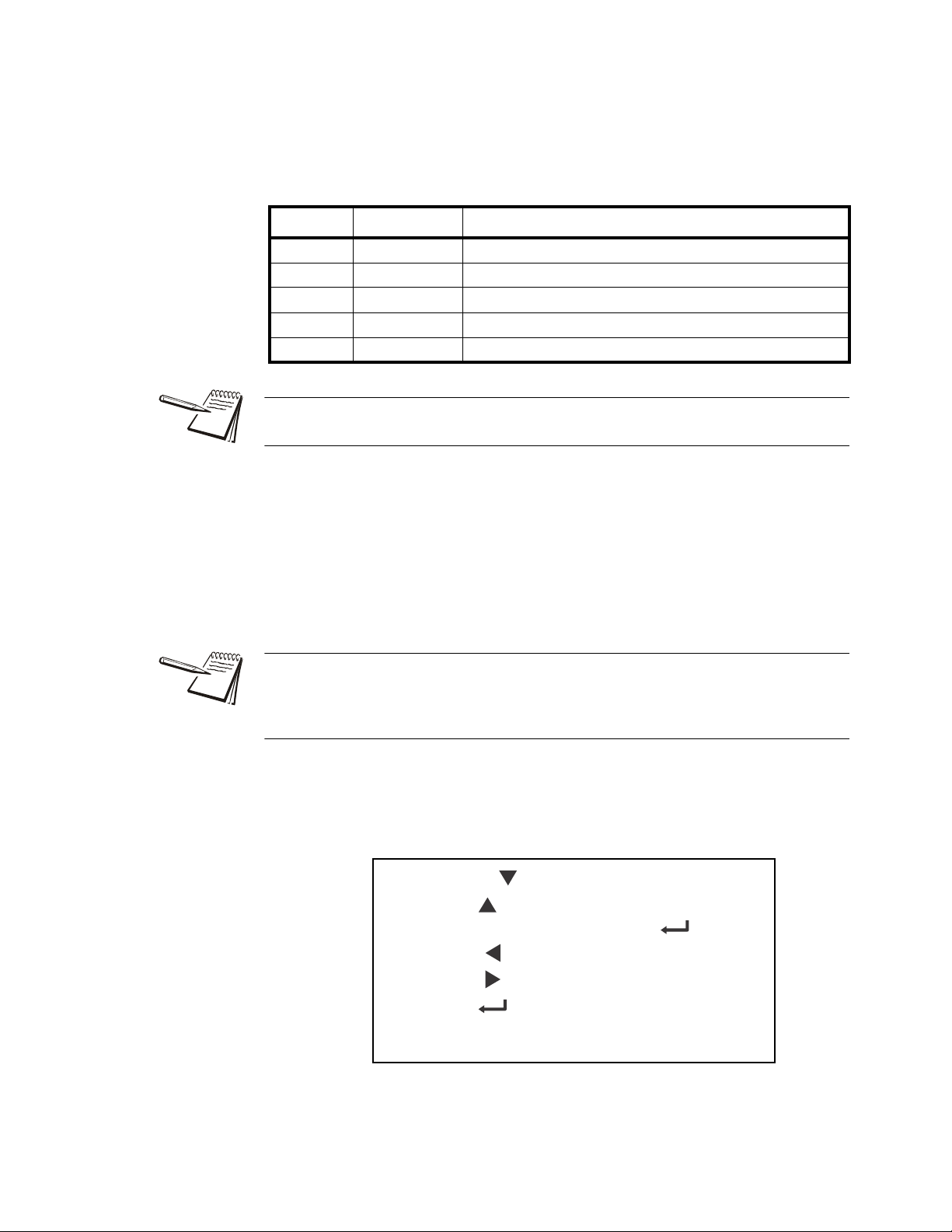
Action TARE SELECT ZERO PRINT UNITS F1
Momentary Key Press
Long Key Press
Action TARE SELECT ZERO PRINT UNITS F1
Single Key Press
Long Key Press
2.6 String index/character data entry
l delete an existing index number.
Table 1: Key Action When In The String Index Select Mode
Selects the index
Deletes current
character
character for editing
using the key actions in
EXIT
Table 2
Inserts new character
Deletes current
character
before this point.
Default character
EXIT
added is 32 (space)
l After you select the index number, use the Table 2 key actions to edit the
Moves left one
position in the
index
Page Up
(Decrements
index by 10)
Moves right
one position in
the index
Page Down
(Increments
index by 10)
character for that index number.
Table 2: Key Action When In The Character Edit Mode
Increments the
flashing digit by
1
Move flashing
digit left
Decrements
the flashing
digit by 1
Move flashing
digit right
Enter
Enter
Delete flashing
digit
Delete the
entire entry
Add Digit ESC/Abort
Does nothing ESC/Abort
Escape Edit
mode and
Abort all
changes
Escape Edit
mode and
Abort all
changes
ZM400 Series Indicators Service Manual 19
Page 20
3 Introduction to the menus
Press SELECT/ to move down in a menu
Press TARE/ to move up in a menu, except at the
bottom item in a menu, then use ZERO/ or F1
Press PRINT/ to move left in a menu
Press UNITS/ to move right in a menu
Press ZERO/ to accept a value or choice and
move up in the menu.
Press F1 to escape and move up in the menu
Menus, accessed through passwords, are available in the indicator to customize and
configure the indicator for your purposes. The menu levels and their passwords are
shown below:
Password Menu Level Accessed Menus
111 USER User, About, Audit
3570 DIAGNOSTICS Diag, User, About, Audit
3088 ADMIN Setup, Diag, User, About, Audit
2580 CALIBRATE Calib
1793 SUPER Application specific items. See User manual.
The CALIBRATE menu level accesses the calibration procedure only. You can also
access the calibration menu through the Setup menu using the ADMIN password.
Some menus appear in more than one menu level. As you can see in the ta ble above,
the 111 password gives you access to three menus; User, About and Audit. The 3570
password gives you access to those three plus the Diagnostics menu. The 3088
password gives you access to those four plus the Setup menu.
This allows the supervisor to control access to some or all of the menus b ased on the
passwords shared. The menus are the same no matter which menu level you access
them from.
The menus are always explained in a sequential manner to cover all information in a
logical fashion. You will probably never access all the menu items in this manner . You
can navigate to the area of the menu that needs to be changed by using the menu
maps and key navigation legends which are inserted as a reminder with most menus.
See Alphanumeric entry procedure (ZM401 only) on p age 17 for instructions on how to
enter a password to get to the menus. Key functions in the menu s ar e sho wn be low.
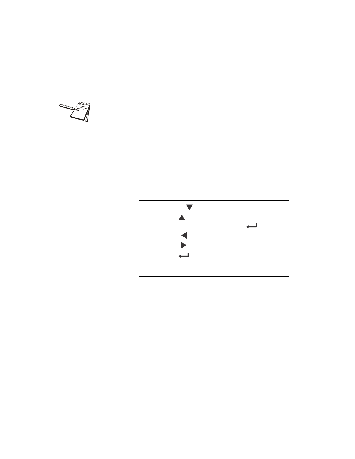
Menu Navigation Keys:
ZM400 Series Indicators Service Manual 20
Page 21
3.1 Accessing the menus
Press SELECT/ to move down in a menu
Press TARE/ to move up in a menu, except at the
bottom item in a menu, then use ZERO/ or F1
Press PRINT/ to move left in a menu
Press UNITS/ to move right in a menu
Press ZERO/ to accept a value or choice and
move up in the menu.
Press F1 to escape and move up in the menu
Follow these steps to access the various menus in the indicator.
1. With the indicator powered up and in normal operating mode, press and hold
the F1 key …
Pass is briefly displayed, then a flashing 0, prompting you to enter the
password.
When the 0 is flashing, press F1 and the application name is briefly displayed, then
the indicator returns to normal operating mode.
2. Key in the p assword for the menu you want to access and press the ZERO key
to accept it …
The first item in the top level of the menu you accessed is displayed.
3. Use the navigation keys, shown below, to navigate through the menu
structure. The symbols appear on the bottom of the keys.
3.1 Accessing the menus
Menu Navigation Keys:
3.2 Exiting the menus
1. If you are at the bottom item in a menu use ZERO to accept a choice or value
and move up a level, or use F1 to escape and move up one level without
accepting the choice or value. From that point, press the TARE key repeatedly
until …
SAVE no is displayed. This means “Do not save changes. “
2. Use the PRINT or UNITS key to scroll through the choices: SAVE no,
SAVEYES and CAnCEL. Press ZERO to accept the displayed choice.
If you choose SAVE no or SAVEYES the indicator exits the menu and
ZM400 Series Indicators Service Manual 21
If you choose CAnCEL, the indicator remains in the menu.
returns to normal weighing mode.
OR
Page 22

3 Introduction to the menus
3.3 Menu annunciators
The menu structure is made up of menu items, parameters, value entry screens and
lists from which you choose one item. To help you know where you are in the menu,
the bar graph at the top of the display is on while the indicator is in the menus and will
change appearance according to the following rules:
All segments flashing This means you are in the menu structure but not
Center flashing / others off This means you are in a numeric entry screen or
in any of the following screens.
the Quick Code prompt screen. See Quick Code
parameter entry on page 23. Enter a number and
press ZERO to accept.
Right flashing / others off This means you are in a list. Scroll through the
choices with the PRINT and UNITS keys and
press ZERO to accept.
Left flashing / others off This means you are in a data entry. See String
index/character data entry on page 18 for more
information.
Every alternate segment flashing This means you are in octet entry for IP, Subnet
or Gateway address.
22 ZM400 Series Indicators Service Manual
Page 23
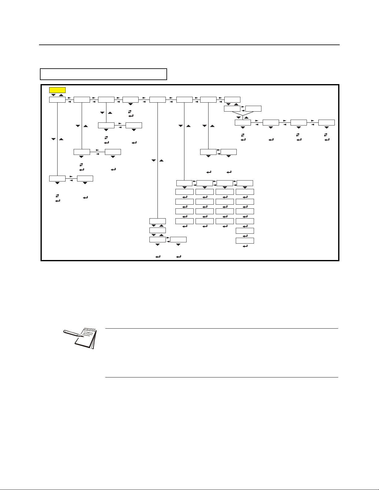
3.4 Quick Code parameter entry
Setup AuditUser
Diag
About
54321
SerialApp. EnetOptionFirmBoot Dload
4.1 4.2
4.3
4.4
4.5 4.6
4.7
Site ID
SealTime Date
3.13.23.33.4
Buttons Ports InputsDisplayScale Options LogsOutputsCur.Zero
2.1 2.2 2.3 2.4 2.5 2.6 2.7 2.8 2.9
Calib Scale System Ports
1.1 1.2 1.3 1.4
E-net Protcl P. F. Ed it PLC Printer OptionsFileSerial
1.4.1 1.4.2 1.4.3 1.4.4 1.4.5 1.4.6 1.4.8 1.4.9
Port1 Port2
1.4.1.1 1.4.1.2
Site Display Buttons D-vals Tare Config Archive Serial Update Passwd
1.3.1 1.3.2 1.3.3 1.3.4 1.3.5 1.3.6 1.3.7 1.3.8 1.3.10 1.3.11
Capacty
Dvision Units Stable AZT Filter Ranges
1.2.1.1 1.2.1.2 1.2.1.3 1.2.1.4 1.2.1.5 1.2 .1 .6 1.2.1.7
Scale 1
1.1.1
Zero Span Linear Input Gravity
Display
Cal.Unit Print
1.1.1.1 1.1.1.2 1.1.1.3 1.1.1.4 1.1.1.5 1.1.1.6 1.1.1.7 1.1.1.8
Z-Lock
1.3.12
BSQ
4.8
BSQ
2.10
Scale 2
1.1.2
Scale 1
1.2.1
Scale 2
1.2.2
2,3,Range Type
1.2.1.8 1.2.1.9
Beeper
1.3.13
Num Scl
1.3.14
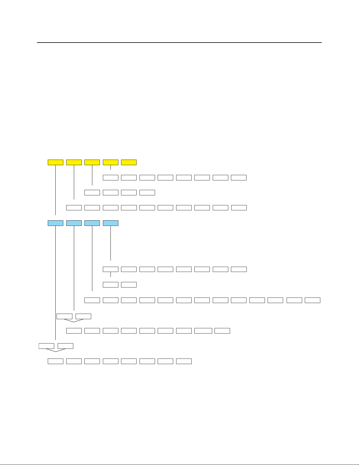
The Quick Code parameter entry let s you quickly jump to sections of the menu. Here’s
how it works:
1. Access the 3088 ADMIN menu. Press and hold the ZERO key for one second.
When you release the key …
P- 0 is displayed and the three center bargraph segments flash.
2. Refer to the Quick Code table in Figure 3.1, find the parameter you want to
access, key in that number and press ZERO …
The screen will show the associated menu item.
3. Use the normal procedures to set the menu item and to save the changes you
make.
3.4 Quick Code parameter entry
Figure 3.1 Quick Code table
ZM400 Series Indicators Service Manual 23
Page 24
4 User level menus
See
page 24
See
page 27
See
page 31
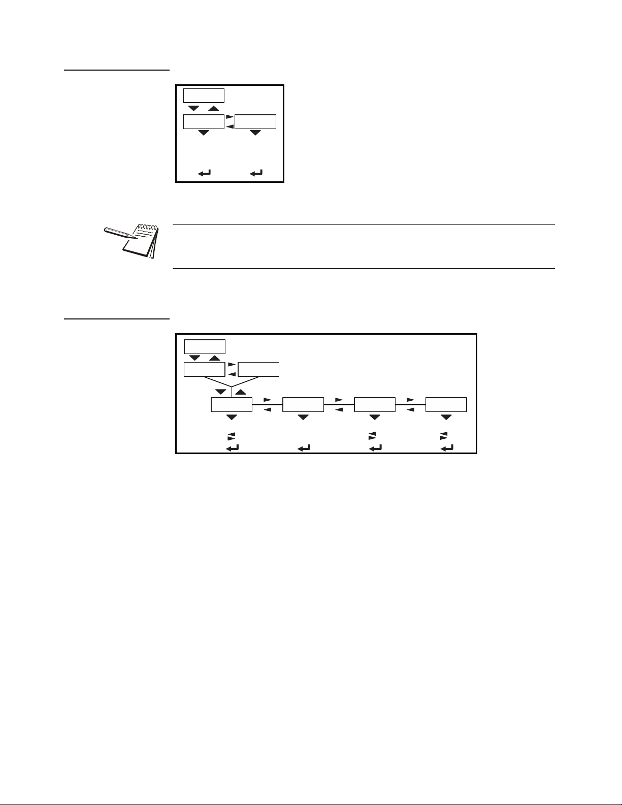
User About Audit
User
Site ID SealTime Date
Set
12hr 12hr-AP 24hr
Set Style
MMDD4YMMDD2Y DDMM2Y DDMM4Yy- x
m- x
d- x
Style
h- x
m- x
s- x
Reference
Alphanumeric entry procedure
Enter
Site ID
View Seal
Status
4 User level menus
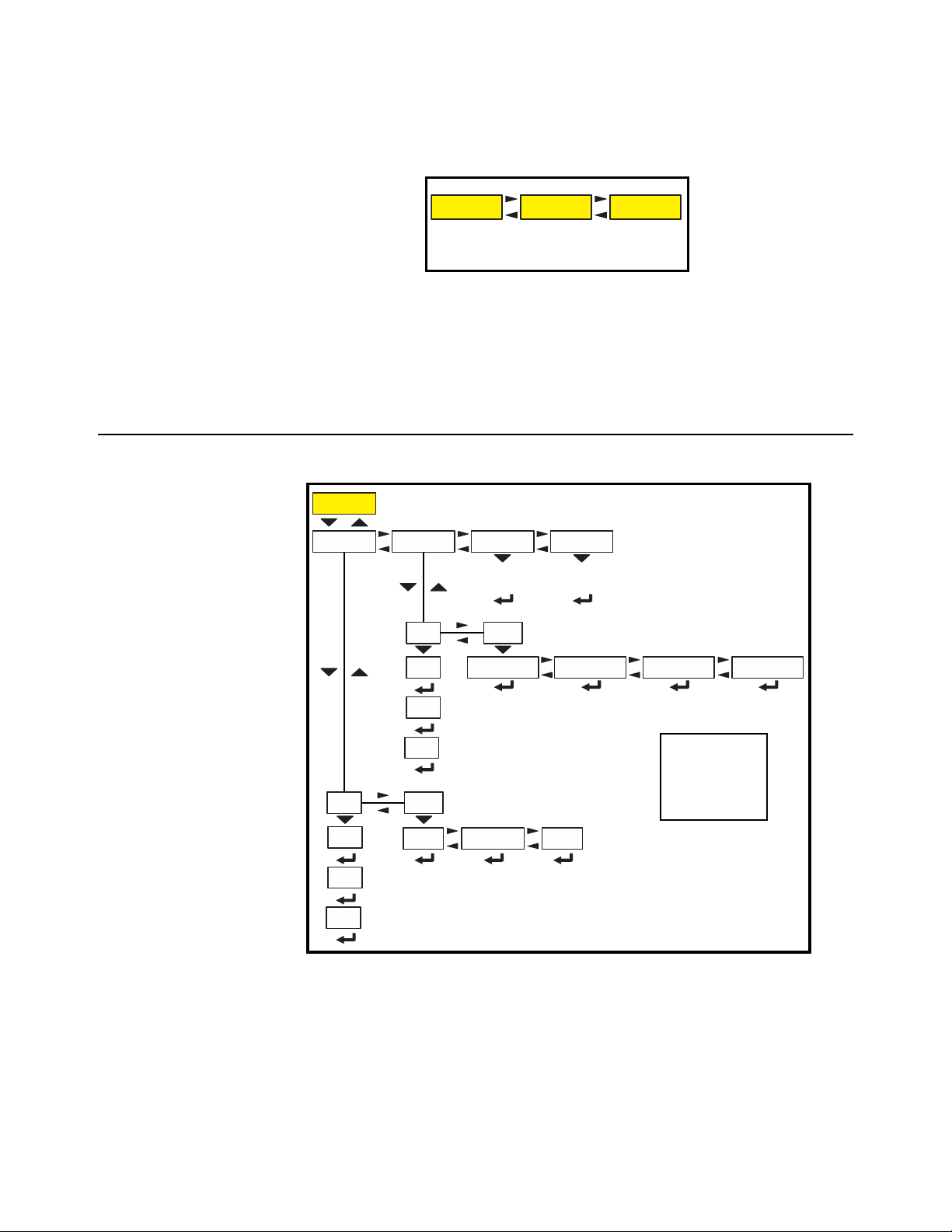
The USER level (password 111) contains the User, About, and Audit menus arranged
as shown in Figure 4.1.
Figure 4.1 USER level (password 111) menus
To access the USER level, from normal weighing mode, press and hold the F1 key.
Enter password 111 and press the ZERO key .
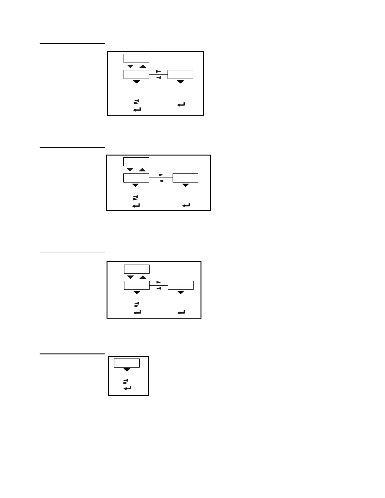
4.1 User menu
The User menu is shown in Figure 4.2.
24 ZM400 Series Indicators Service Manual
Figure 4.2 User menu
Use this menu to set the time, date, site ID, and to see the physical seal status. Each
is explained below:
Page 25
4.1.1 Time
Use the tiME menu item to set the clock
(SEt) and to choose the style of the time
display (StYLE) 12 hr, 12 hr AM/PM or
24 hr.
Time
Set
12hr 12hr-AP 24hr
Style
h- x
m- x
s- x
Date
Set Style
MMDD4YMMDD2Y DDMM2Y DDMM4Yy- x
m- x
d- x
4.1 User menu
The Time and Date can be used in print formats.
SEt Use this to enter values for the time.
h- x, = Hour
m- x = Minute
s- x = Seconds
4.1.2 Date
StYLE Choose the style of the time display. Choices are:
12hr, = 12 hour clock
12hr-AP = 12 hour clock with AM/PM
24hr = 24 hour military time
Use the dAtE item to set the year, month and day and the style of the displayed date.
SEt Enter values for the date.
y- x = Year
m- x = Month
d- x = Day
ZM400 Series Indicators Service Manual 25
Page 26
4 User level menus
Site ID
SitE Use this to enter a Site ID.
The Site ID can be used in a print format. Use the
alphanumeric entry methods described in 2.3 and 2.4 to
enter a Site ID. (maximum 6 digits)
Enter
Site ID
Seal
SEAL Use this to view the seal status of the indicator.
This is the status of the physical seal jumper inside the
indicator. If the unit is sealed, no changes can be made to
the configuration of the indicator. See the note below.
View Seal
Status
4.1.3 Site ID
4.1.4 Seal
StYLE Choose the style of the date display. Choices are:
MMdd2Y = Month, Day, 2-digit Year
MMdd4Y = Month, Day, 4-digit Year
ddMM2Y = Day, Month, 2-digit Year
ddMM4Y = Day, Month, 4-digit Year
The seal switch jumper, E7, is located in the top lef t quadrant of the main PCB. See
ZM umper and switch settings on page 142. If the jumper is installed, the indicator is
sealed. This means the only the Diagnostic, User , About, Audit and Supervisor menus
can be accessed. Other menus cannot be accessed - the display will flash SEALEd.
To exit the menu, see Exiting the menus on page 21.
26 ZM400 Series Indicators Service Manual
Page 27
4.2 About menu
About
SerialApp. EnetFirmBoot
VersionPartno
VersionPartno
VersionPartno
Dload
Sserial Dserial
AWT30 XXXXX X.X.X.XX
AWT30 XXXXX X.X.X.XX
AWT30 XXXXX
X.X.X.XX
IP GatewaySubnet Mac
1 xx
2 xx
3 xx
4 xx
5 xx
6 xx
1 xx
2 xx
3 xx
4 xx
1 xx
2 xx
3 xx
4 xx
1 xx
2 xx
3 xx
4 xx
Option BSQ
VersionType
Bus 1
Card 1
Scale 1 Scale 2
Version
SW Part
Cur.Ser Cal.Ser
xxxx xxxxx
X.X.X.XX
AWT30 XXXXX
xxxx xxxxx xxxx xxxxx
Reference Alphanumeric entry procedure
View App PN
View SN
View version
View version
View version(View
bootloader PN)
(View Firmware PN)
(View
license
number)
(View
license
number)
(View card
description)
(View card
version)
View SN View SNView version(View App PN)
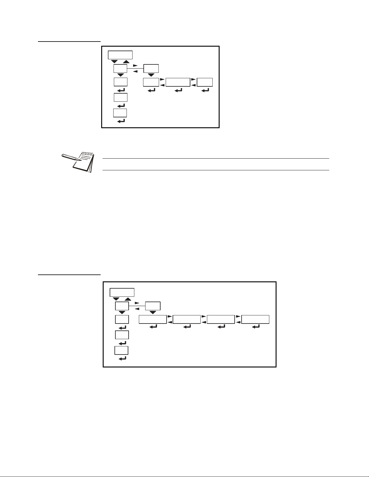
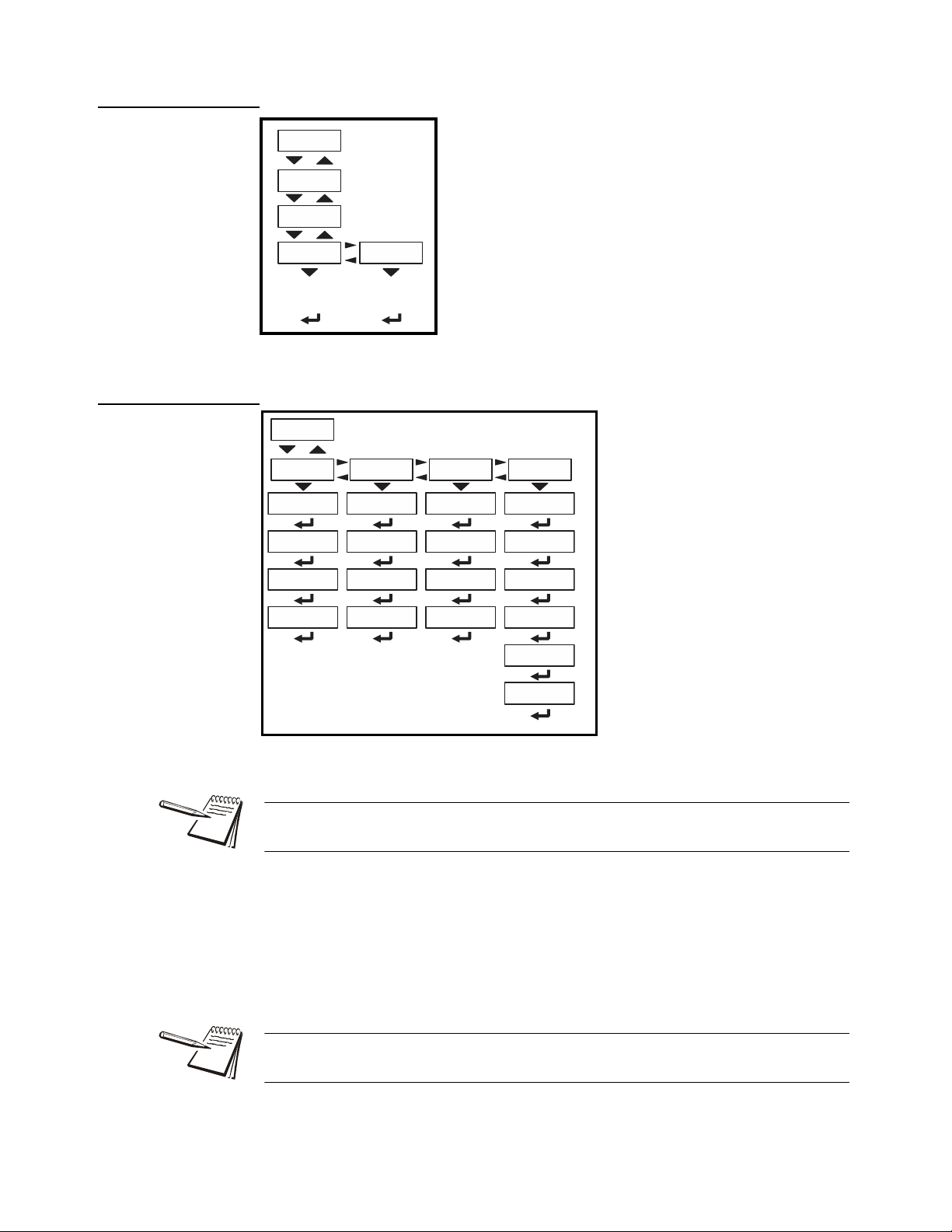
The About menu is shown in Figure 4.3.
4.2 About menu
Use this menu to display information about the various items shown in Figure 4.3. Each
is explained below:
Definitions:
Bootloader Software that makes the electronics run.
Firmware Embedded system software that creates core functions of the product.
App Specific software that controls the behavior fo r a given installation.
ZM400 Series Indicators Service Manual 27
Figure 4.3 About menu
Page 28
4 User level menus
Boot
VersionPartno
AWT30 XXXXX
X.X.X.XX
PArtno Use this to view the bootloader part
number. The part number is
displayed in two parts. Press RIGHT
arrow key or LEFT arrow key to
toggle the display between the first
and second parts of the part number.
VErSion Use this to view the version of the
bootloader.
(View
bootloader PN)
(View version)
Firm
VersionPartno
AWT30 XXXXX X.X.X.XX
PArtno Use this to view the firmware part
number. The part number is
displayed in two parts. Press
RIGHT arrow key or LEFT arrow
key to toggle the display between
the first and second parts of the
part number.
VErSion Use this to view the version of the
firmware.
(View Firmware PN) (View version)
App.
VersionPartno
AWT30 XXXXX X.X.X.XX
(View App PN) (View version)
PArtno Use this to view the App part number .
The part number is displayed in two
parts. Press RIGHT arrow key or
LEFT arrow key to toggle the display
between the first and second parts of
the part number.
VErSion Use this to view the version of the
App.
Serial
xxxx xxxxx
SEriAL Use this to view the Serial Number of the indicator . The
number is displayed in two parts. Press RIGHT arrow
key or LEFT arrow key to toggle the display between the
first and second parts of the serial number.
(View SN)
4.2.1 Boot (Bootloader)
4.2.2 Firmware
4.2.3 App
4.2.4 Serial
28 ZM400 Series Indicators Service Manual
Page 29
4.2.5 Option
Option
VersionType
Bus 1
Card 1
(View card
description)
(View card
version)
Bus 1 There is only 1 Bus in the ZM400.
Card 1 There is only 1 Card in the ZM400.
oPtion Use this to view the descr iption and version of
an installed option card.
Enet
IP GatewaySubnet Mac
1 xx
2 xx
3 xx
4 xx
5 xx
6 xx
1 xx
2 xx
3 xx
4 xx
1 xx
2 xx
3 xx
4 xx
1 xx
2 xx
3 xx
4 xx
4.2.6 Enet
4.2 About menu
ZM400 Series Indicators Service Manual 29
EnEt This stands for Ethernet. Use this to view the network addresses.
If the indicator is connected to an Ethernet network, the values displayed will be the
current assigned addresses.
iP Use this to view the IP address.
SubnEt Use this to view the Subnet address.
gAtEWAY Use this to view the Gateway address.
MAc Use this to view the Mac address.
The IP, Subnet and Gateway addresses are a series of four double digit values.
The MAC address is a series of six double digit values: 1 XX, 2 XX, 3 XX, etc.
Page 30
4 User level menus
Dload
Sserial Dserial
dLoAd This stands for download. Use this to view
these items:
SSEriAL View the license number that
created the configuration file.
dSEriAL View the license number that
downloaded the configuration
file.
This is used for security and licensing purposes.
(View
license
number)
(View
license
number)
BSQ
Scale 1 Sc ale 2
Version
SW Part
Cur.Ser Cal.Ser
X.X.X.XX
AWT30 XXXXX
xxxx xxxxx xxxx xxxxx
View SN View SNView version(View App PN)
4.2.7 Download
4.2.8 BSQ
To upload a configuration file, the license number of the Configurator (Ztools)
software must match one of the license numbers in the indicator Contact AWTX
Technical Support for assistance.
30 ZM400 Series Indicators Service Manual
This stands for Bench Scale - Quartzell.
SW PArt View the firmwa re part number of the cell that is connected.
VErSion View the firmware version of the cell that is connected.
cur.SEr View the serial number of the cell that is connected.
cAL.SEr View the serial number of the cell that WAS connected at the time of
calibration.
To exit the menu, see Exiting the menus on page 21.
Page 31

4.3 Audit menu
Audit
PrintCounter
Config Calib
Port 1 Port 2 USB
Column Ticket
Column Ticket
Displays
number of
configurations
Displays
number of
calibrations
Counter
Config Calib
countEr Use this to view these items:
conFig View how many times the
indicator has been
configured.
cALib View how many times the
indicator has been
calibrated.
Displays
number of
configurations
Displays
number of
calibrations
4.3 Audit menu
Figure 4.4 Audit menu
Use this menu to display audit counters for configuration and calibration and to pr int the
information. Each is explained below:
4.3.1 Counter
ZM400 Series Indicators Service Manual 31
Page 32

4 User level menus
Print
Port 1 Port 2 USB
Column Ticket
Column Ticket
4.3.2 Print
Print Use these to select which port to print the audit report through. Choices
are:
Port 1 Under Port 1 choose to print to a column or ticket printer.
Port 2 Under Port 2 choose to print to a column or ticket printer.
uSb Printing to USB requires that a USB flash drive is connected
to the indicator host USB. Printing to USB will create a folder
on the flash drive and a comma separated file with the data.
To exit the menu, see Exiting the menus on page 21.
32 ZM400 Series Indicators Service Manual
Page 33

5 Diagnostics level menus
See page 24 See page 27 See page 31See page 33
Diag User About Audit
Ports OptionsOutputs
USB
Cur.Zero
Value Clear
1 2 3
ButtonsDisplay Logs
Print Clear
Port1 Port2
Clr no Clr yes
Serial1 Serial2
BSQ
Comprss Tens ion
Scale 1 Scale 2
Yes
No
Inputs
Bus 1
Card 1
Scale 1 Scale 2
Diag
Scale
Scale 1 Scale 2
Reference Alphanumeric entry procedure
View scale output
in A to D
counts or mV/V
Continuous
display test
(ZERO exits
the test)
Test button
function
(ZERO exits
the test)
Test
configured
inputs
Toggles
selected
output
on and off
Loopback
test
Performs
write/read
test
Loopback
test
Comp. Freq
displayed
Tension freq
displayed
Test
installed
options
The DIAGNOSTICS level (password 3570) is the same as the USER level except it
adds the Diag menu. The DIAGNOSTICS level is shown in Figure 5.1.
Figure 5.1 DIAGNOSTICS level (password 3570) menus
5.1 Diag menu
Use the Diag menu to check or verify the performance of the indicator. The diagnostic
tests available include: Scale A to D to view output from the connected scale base or
load device, the current zero offset from calibr ation zero, a display segment test, a front
panel keypad or button test, serial Com ports and USB host port test, remote inputs and
outputs test, and an option card test if installed. You can print an error log report that
provides information on previous error conditions such as overloads or underloads.
The Diag menu is shown in Figure 5.2.
5.1 Diag menu
The and symbols stand for direction moved in the menu. So Diag Scale
illustrates that you move down from Diag to Scale. This will help you keep track of
where you are in the menu structure.
Each of the items in the Diag menu is explained below:
ZM400 Series Indicators Service Manual 33
Figure 5.2 Diag menu
Page 34

5 Diagnostics level menus
Scale
Scale 1 Sc ale 2
ScALE Select to view values for Scale 1 or Scale 2, if
installed. Use this to view a number
representing the A to D counts. The value is
only for diagnostic purposes. The value should
increase as weight on the scale increases and
decrease as weight decreases.
Press SELECT to toggle to a mV/V display.
This is an approximate value for the mV/V value
output by the loadcell. If the scale is a BSQ then
you can only view counts, not mV/V.
View scale
output in A to
D counts or
mV/V
Cur.Zero
Value Clear
Scale 1 Scale 2
YesNo
5.1.1 Scale
5.1.2 Current Zero
34 ZM400 Series Indicators Service Manual
cur.ZEro This stands for current zero and represents the weight offset between the
calibration zero setting and the current zero setting due to pu shbutton zero
or Auto-Zero Tracking (AZT) adjustments.
Select to view values for Scale 1 or Scale 2, if installed.
VALuE View the zero offset.
cLEAr Clear the zero offset to return the indicator to calibration zero. Choose Yes
or No.
This can restore the original calibration zero point if the ZERO key is accidently
pressed when a tank or vessel contains product that cannot be emptied.
Page 35

5.1.3 Display
Display
Continuous
display test
(ZERO exits
the test)
diSPLAY Use to test the segments of the display. Each digit
area lights up in progression and continues until you
press ZERO.
Buttons
Test butt on
function
(ZERO exits
the test)
buttonS Use to test the keys. When you begin the test
tESting is briefly displayed followed by dashes.
Press any key to test if it is functioning and its name
or value will be displayed.
Press ZERO to stop the test.
Ports
USBSerial1 Serial2
Loopback
test
Loopback
test
Performs
write/read
test
5.1.4 Buttons
5.1 Diag menu
5.1.5 Ports
PortS Use this to do a loopback test for serial port 1 or 2 or to perform a write/
read test on the USB port.
SEriAL1 or 2 When you pick a serial port to test, tESting is briefly displayed and
then PASS or FAiL, depending on if the send and receive lines are
jumpered (pass) or not (fail). Add a jumper or wire between the
transmit output and receive input. On an external 9 pin connector the
transmit line is pin 2 and the receive line is pin 3.
It is recommended that you insert the jumper (a paper clip works) into the external
cable connector to validate the wiring and not just the internal port s. See System
block diagram on page 141 for I/O configuration of the serial ports TB3.
uSb Use this to test a connected USB flash drive.
oPEn is briefly displayed, then WritE is briefly displayed, then rEAd is
briefly displayed, then PASS or FAiL, depending on if the USB device
is working correctly or not.
ZM400 Series Indicators Service Manual 35
If no USB device is plugged in when you begin the test, oPEn is briefly
displayed, then no uSb is briefly displayed, then uSb.
Page 36

5 Diagnostics level menus
Inputs
Test
configured
inputs
inPutS The input test is used to verify if external switches wired
to the input ports on TB2 are functioning properly.
Follow the steps below to perform the inputs test.
Outputs
1 2 3
Toggles
selected
output
on and off
outPutS The output test is used to verify if external relays or
lights (etc.) connected to TB2 are properly wired
and functioning properly.
Follow the steps below to perform the output test.
5.1.6 Inputs
1. Press SELECT …
in 000 is displayed, if no inputs are jumpered.
2. To test input 1, jumper pins 1 and 2 of the I/O connector on the indicator …
The first digit becomes 1 until the jumper is removed.
3. To test input 2, jumper pins 1 and 3 of the I/O connector on the indicator …
The second digit becomes 2 until the jumper is removed.
4. To test input 3, jumper pins 1 and 4 of the I/O connector on the indicator ….
The third digit becomes 3 until the jumper is removed.
5.1.7 Outputs
5. Press ZERO …
inPutS is displayed.
CAUTION: Be sure to take proper precautions to ensure material controlled by
the scale outputs will not create a hazardous condition during an output test.
1. WithoutPutS is displayed, press SELECT …
outPut1 is displayed.
2. Press SELECT …
o.1-oFF is displayed.
36 ZM400 Series Indicators Service Manual
Page 37

5.1.8 Options
Options
Bus 1
Card 1
Test
installed
options
outPutS Use this to test the various installed option cards.
buS 1 Refers to Bus 1, where the option card is
attached.
cArd 1 Refers to the option card that is installed.
Logs
Print Clear
Port1 Port2
Clr no Clr yes
5.1 Diag menu
3. Press PRINT or UNITS to toggle the output on (o.1-on) and repeat to turn it
oFF.
Output 1 will be toggled on and off as you press the keys. This is shown
by the annunciator (SP1) on the display turning on and off.
4. Press ZERO or F1 to stop the test …
outPut1 is displayed.
5. Press UNITS to go to the next output. Repeat the steps to test output 2 and 3.
6. When finished, press TARE …
outPutS is displayed.
5.1.9 Logs
ZM400 Series Indicators Service Manual 37
The logs report will print any error conditions that may have occurred such as
overloads and underloads
LogS These are logs of various functions. You can print or clear them from
memory.
Print Choose to print the log from Port 1 or Port 2.
cLEAR Choose to clear the log from memory.
Page 38

5 Diagnostics level menus
BSQ
Comprss Tension
Scale 1 Sc ale 2
Comp. freq.
displayed
T ension freq.
displayed
5.1.10 BSQ
bSQ The BSQ menu item provides the digital frequency information for the
crystals on the QDT (Quartzell Digital Transducer).
ScALE 1 or ScALE 2:
Select which Scale number the BSQ is assigned, ScALE 1 or
ScALE 2
coMPrSS This stands for compression frequency.
tEnSion This stands for tension frequency.
The nominal value for the tension and compression frequency is 47,200 ± 2000 kHz.
The tension and compression frequencies should each be as stable as the other and
within 10% of each other. As weight increases the tension frequency should increase
and the compression frequency should decrease.
This completes the Diag menu. To exit the menu, see Exiting the menus on page 21.
38 ZM400 Series Indicators Service Manual
Page 39

6 ADMIN level menus
See page 24 See page 27 See page 31See page 33See page 39
Setup Diag User About Au dit
See page 40 See page 46 See page 54 See page 65
Setup
Calib
Scale System Ports
The ADMIN level (password 3088) is the same as the DIAG level except it adds the
Setup menu. The ADMIN level is shown in Figure 6.1.
6.1 Setup menu
In the Setup menu there are various submenus available to configure specific sections
of the scale operation. The top level items in the Setup menu are shown in Figure 6.2.
6.1 Setup menu
Figure 6.1 ADMIN level
Figure 6.2 Setup menu (password 3088)
Each of the items in the Setup menu are explained in the following sections.
ZM400 Series Indicators Service Manual 39
Page 40

6 ADMIN level menus
Calib
Zero Linear Input Gravity
LastCal.Zero Temp
Zero Span
Counts mV
Counts
mV
XXXX
USB
Print
Port 1 Port 21000g
Cal.Unit
LB
Display
G-fact Lat Alt Calc
Pt2 Pt9
Span
Scale 1 Scale 2
View or
enter new
span
Live weight
displayed.
Place span
weight on
scale
Enter
Pt 2 test
weight
Live weight
displayed.
Remove
all weight.
Live weight
displayed.
Live weight
displayed.
Place Pt 9
weight on
scale.
Enter
Pt 9 test
weight
View or
enter
G-factor
Enter
latitude
View
live weight
(F1 to stop)
Enter
altitude
Calculate
s gravity
factor
Live weight
displayed.
Live weight
displayed.
Live weight
displayed.
Place Pt 2
weight on
scale.
Live weight
displayed.
to
6.2 Calibration Procedure
Use the Calib menu to perform Zero and Span calibration, add Linearity correction
points, manually input calibration parameters for Zero and Span, manu ally input
Gravitational correction values, view the live weight, set the calibration unit of me asure
and print out a calibration report. Follow the menu in Figure 6.3 and the steps that
follow.
Access the calibration procedure directly using the calibration password, 2580, or
access it through the Setup menu, password 3088. See Alphanumer ic entry procedure
(ZM401 only) on page 17.
6.2.1 Scale 1-2
40 ZM400 Series Indicators Service Manual
Select the scale to be calibrated, Scale 1 or Scale 2. The Number of Scales on page
64 must be set to 2 to access Scale 2 settings.
Figure 6.3 Calibrate menu
Page 41

6.2.2 Zero Procedure
Zero
LastCal.Zero Temp
Live weight
displayed.
Remove all weight.
Live weight
displayed.
ZEro Access the scale zeroing process.
On the initial zero calibration of the indicator to a new scale, the zero cal counts may
appear unstable. Continue to the span calibration and when completed the condition
should correct itself.
6.2 Calibration Procedure
cAL.ZEro Use this to record the zero point. Follow the menu above to
complete the zero calibration. A c on the display denotes the
fact you are in the calibration procedure.
tEmP This is an alternate zeroing procedure. Use this when the
product weight on the scale, such as in a tank or vessel,
appears to be inaccurate but cannot be re move d to establish
a no-load condition.
Enter the calibration procedure and select Temp. zero. The
current weight on the scale will be temporarily assigned as the
Cal Zero value. Continue to the SPAN procedure, key in the
value of the test weights and place them on the scale and
complete the SPAN procedure. The original Cal Zero is
restored after exiting the span procedure and the current
product weight will now be correctly represented.
Due to factors that created the original inaccuracy, it may be
necessary to re-zero the scale when the tank or vessel is
empty.
LASt This is an alternate zeroing procedure. Use this if certified test
weights placed on the scale display a slightly inaccurate
value. Be sure that the scale is at zero before the test weights
are added and enter the calibration procedure and select Last
zero. The last acquired zero value will be assigned as the new
Cal Zero value.
Continue to the SPAN procedure without removing the test
weights. Key in the value of the test weights on the scale and
complete the SPAN procedure. The test weights will now read
accurately.
ZM400 Series Indicators Service Manual 41
Page 42

6 ADMIN level menus
Span
View or
enter new
span
Live weight
displayed.
Place span
weight on
scale.
Live weight
displayed.
SPAn To set the Span Calibration point press the DOWN
arrow key and XXXX is displayed with a flashing
right digit. This is the current span weight.
Press ZERO to accept the displayed span weight o r
key in your span weight (not to exceed the
configured capacity) and press ZERO.
c xxx is displayed. This is the current weight on the
scale.
Place the span weight on the scale and pre ss ZERO.
buSy is briefly displayed and then c XXXX is
displayed, which should be the same as the span
weight you keyed in. Press ZERO and SPAn is
displayed.
Linear
Pt2 Pt9
Enter
Pt 2 test
weight
Live weight
displayed.
Place Pt 2
weight on
scale.
Live weight
displayed.
Live weight
displayed.
Enter
Pt 9 test
weight
Live weight
displayed.
Place Pt 9
weight on
scale.
to
6.2.3 Span Procedure
6.2.4 Linearity Procedure
42 ZM400 Series Indicators Service Manual
Perform the linearity procedure only if test weights applied to the scale between the
zero and span calibration points are showing slight inaccuracies, such as ± a few
divisions. If large inaccuracies are recorded, this indicates a possible mechanical
problem or possible loadcell failure which linearity calibration may not be able to
correct.
LinEAr Add up to eight additional calibration points to improve the linearity
performance of the scale.
Page 43

Linearity points are cleared if a new span calibration is performed.
Input
Zero Span
Counts mV
Counts mV
XXXX
6.2.5 Input procedure
6.2 Calibration Procedure
Pt2-Pt9 The points are numbered 2 through 9 because, internally, the
zero reference point is point 1 and the span point is point 10.
Follow the same steps as described in the SPAN procedure to
enter each linearity point.
ZEro Use this to enter a value for the zero point.
CountS Use this to enter a zero point using ADC counts.
mV Use this to enter a zero point using a mV/V value.
SPan Accept the flashing displayed span weight (XXXX) or key in the span
weight that corresponds with the span ADC or mV/V value.
CountS Use this to enter a span using ADC counts.
mV Use this to enter a span using a mV/V value.
The BSQ base only allows entry of Counts for Zero or Span points
The Span value is the differenti al valu e of th e actual Ca libration Zero and Sp an count
(or mV/V) values.
ZM400 Series Indicators Service Manual 43
Page 44

6 ADMIN level menus
Gravity
G-fact
Lat Alt Calc
View or
enter
G-factor
Enter
latitude
Enter
altitude
Calculates
gravity
factor
6.2.6 Gravity Factor Procedure
grAvitY Use this item to key in a gravity constant value. If the scale has been
calibrated at a different location that has a significantly different
gravitational factor than the installation site, and it is not possible to recalibrate with known test weights, the scale can be adjusted using this
gravity factor.
g-FACt If you know the local gravitation factor (allowable range is
9.70000 to 9.90000), key it in here
OR
If you do not know the local gravitation factor but can
determine the approximate latitude and altitude of the
installation site, then the indicator can calculate the gravity
factor from these two values.
LAt This stands for latitude. Key in the latitude for the installation
site. The valid range is 0 to 90. A positive value works for n orth
or south of the equator. Altitude
ALt This stands for altitude. Key in the altitude for the installation
site. The valid range is 0 to 30,000 ft. (10000 m).
CALC This stands for calculate. The indicator calculates the grav ity
factor and loads this value as the gravity factor.
Be sure to save the changes when you exit the menu an d test the accuracy with a know
weight.
CAUTION: Verify with local agencies if adjusting the gravity factor is accepted
in your area. It may be required that calibration be done with certified weights.
44 ZM400 Series Indicators Service Manual
Page 45

6.2.7 Display
View live
weight
(F1 to stop)
diSPLAY Use this item to view live scale weight while in the
calibration menu.
Display
1000g
Cal.Unit
LB
CAL.unit Use this item to set the unit of measure of the
weights used during calibration. Choices are
Lb or 1000g.
Print Use this print function to print a
calibration report through Port 1, Port 2
or to USB. This information can be used
in the future to restore calibration.
See Calibration report on page 104 to
view a representation of the printed
report.
USB
Print
Port 1 Port 2
Use the ZERO key to zero the indicator so you can add test weights to validate the
accuracy of the scale.
6.2.8 Calibration Unit
6.2 Calibration Procedure
6.2.9 Print calibration report
This completes the Calib menu. To exit the menu, see Exiting the menus on page 21.
ZM400 Series Indicators Service Manual 45
Page 46

6 ADMIN level menus
Scale
Capacty Dvision Units Stable AZT Filter Ranges Type
Mode
0-rnge O-cap G-zero
Basis
Percent Div
O-Load U-Load
Avg
Const T-hold
Div Time
Unit
Ratio1 String1
Custom
Cust 1 Cust 4
Unit 1
Unit 2 Unit 3 Unit 4
0.000001 0.00002 0.00005 100 200 500
OffCust 2 Cust 3 Cust 4Lb 1000 g
Oz
Gr Lb-oz Cust 1
Scale 1 Scale 2
CAP 1 CAP 2 Div 1 Div 2 Type
M.range M.intrvl
2,3,Range
0.000001 500
0.000001 500
Option Protcl Disable Onbrd
Bind
Bus Card
Bus X Card X
Bind
Prot 1 Prot 10
Div
Time
Key in
scale capacity
to
Key in
value
Edit
string
Not for
Unit 1
Key in
value
Key in
time
Key in
value
1 thru 10 Key in
value
Key in %
of scale
capacity
Key in value
based on Basis
chosen
Key in 0 to
10000 div.
Key in
CAP 2
capacity
Key in
CAP 1
capacity
Key in
value
Key in
time
to
to
to
If Mode is
Option
If Mode is
Protcl
to
6.3 Scale
CAUTION: Be sure you follow all local weights and measures regulations.
Some parameters may be set automatically by your choice of SitE in the
System menu item.
Use the Scale menu to configure the scale operating parame ters such as capacity and
division size, available units of measure, motion and auto zero tracking values, filtering
parameters, range of operation for zeroing the scale, over and underload conditions
and the return to gross zero region or band. Refer to the menu in Figure 6.3 and the
steps that follow.
46 ZM400 Series Indicators Service Manual
Figure 6.4 Scale menu
Page 47

6.3.1 Scale 1-2
Scale 1 Sc ale 2
ScALE 1-2 Select the scale to setup, ScALE 1 or
ScALE 2.
The Num Scl menu item in the SYSTEM
menu, on page 64 must be set to 2 to access
Scale 2 settings
Capacty
Key in
scale capacity
cAPActY Key in a new capacity or accept the displayed
capacity.
0.000001 0.00002 0.00005
100
200 500
Dvision
to
6.3.2 Capacity
6.3 Scale
Access the Scale menu. See Alphanumeric entry procedure (ZM401 only) on page 17.
The capacity that you enter should never exceed the rated cap acity of the scale that is
connected.
6.3.3 Division
dViSion This stands for division size.
Choices are 0.000001, 0.000002, 0.000005, 0.00001, 0.00002, 0.00005,
0.0001, 0.0002, 0.0005, 0.001, 0.002, 0.005, 0.01, 0.02, 0.05, 0.1, 0.2, 0.5,
1, 2, 5, 10, 20, 50, 100, 200 and 500. The default value is 1.
Division sizes for other units of measure are automatically calculated by the indicator.
ZM400 Series Indicators Service Manual 47
Page 48

6 ADMIN level menus
Units
Unit
Ratio1 String1
Custom
Cust 1 Cust 4
Unit 1 Unit 2 Unit 3 Unit 4
OffCust 2 Cust 3 Cust 4
Lb 1000 g Oz Gr Lb-oz
Cust 1
to
Key in
value
Edit
string
Not for
Unit 1
6.3.4 Units
unit From this item you can choose which units of measure are available when
cuStoM This stands for custom unit. To use a custom unit you must first create
the user presses the UNITS key during normal weighing. You can have up
to four units for viewing. They are listed as: unit 1, unit 2, unit 3 and unit
4. You can assign any of the following units of measure to any of these: lb,
1000g, oz, gr, lb-oz, cuSt 1, cuSt 2, cuSt 3, cuSt 4 or oFF.
them by entering a ratio and a string to define it. See the section below on
creating a custom unit before continuing with the rest of the unit menu item.
You can ignore all the 10x steps if you do not want to create a custom unit
of measure.
cuSt 1-4 You can set up one to four custom units. The process to set
up a custom unit is the same for all four.
rAtio The ratio is the number you divide into the
calibration unit of measure to create the custom
unit. Example: Ratio would equal 2000 if you
wanted to convert pounds to tons.
String Use this to enter a string label for the custom unit.
Refer to String index/character data entry on
page 18 for instructions on how to enter a string
label. This is only used when data is transmitted
out one of the communication ports.
48 ZM400 Series Indicators Service Manual
Page 49

6.3.5 Stable
Stable
Div Time
Key in
value
Key in
time
AZT
Div Time
Key in
value
Key in
time
6.3 Scale
StAbLE Use this parameter to set the stability window for the scale. Set a division
window and a time window which will be used to determine when the
stability icon will be displayed.
diV Set the division window size to define stability.
timE Set the time window in seconds to define stability. Set both
diV and timE to 0 to disable stability.
The StAbLE time value is used during normal operation as the length of time the
indicator will continue to check for a ‘motion stable’ condition after the ZERO, TARE
or PRINT button is pressed. If the intended operation can not be completed befo re the
timeout, cAnt is displayed and the key request is ignored.
6.3.6 AZT
AZt This stands for Automatic Zero Tracking. The diV value defines a ± range
around zero. When scale weight is not at the center of zero but inside this
range for the time value entered, ½ of the weight will be subtracted. This
process is repeated until weight is inside the center of zero region.
diV Set the AZT window size to define stability. 3 divisions is the
default value. Set diV to 0 to disable AZT.
timE Set the time window in seconds. 1 second is the default value.
Set to 0 to disable AZT.
In certain applications, such as when batching product that starts falling slowly onto
the scale, it may require disabling AZT or changing the default values to reduce the
effect.
ZM400 Series Indicators Service Manual 49
Page 50

6 ADMIN level menus
Filter
T-hold
Avg
Const
Key in
value
1 thru 10 Key in
value
6.3.7 Filter
FiLtEr Use this to filter out vibrations affecting the scale. Under this item you have
the following three parameters to set.
AVg This stands for average. 10 is the d e f ault va l u e .
conSt This stands for constant. 1 is the def ault va l u e .
t-hoLd This sta nds for thre sho ld. 1 00 is the default value. When 0 is
the threshold value, filtering is always on.
To find the best settings for your filter needs, follow steps 1 to 7.
Default settings are:
AVG = 1 0
Const = 1
t-hold = 100 (factory default based on 5000 lb capacity)
These values will provide the best weight response for the majority of scale
installations. In adverse conditions, where wind, vibration or other conditions are
affecting the stability of the weight displayed, refer to the following instructions to
improve the performance of the indicator.
If you are using Ztools to configure your scale it will attempt to calculate
filtering based upon your capacity and division size used.
1. Using the Threshold setting is only r ecommended if the items to be weighed are
similar in weight. If the item weights vary considerably then set the threshold
value to 0 and proceed to step 2.
To determine the threshold value first set t-hoLd to 0.0, conSt to 0, and AVg to
1.0. Return to weigh mode and, with a typical item on the scale, observe the
weight swings. Record the difference between the highest and lowest displa yed
weight values. Add 30 to 50% to this value. This is a good starting value for the
t-hoLd setting. Do not set your indicator to this value until told to in step 7.
2. Setting AVg to higher values increases the filtering effect.
To do this: Set t-hoLd to 0.0, conSt to 0, and AVg to 10. Check the stability of
the scale by exiting to normal weigh mode, remove all weight from the scale
and/or press ZERO and observe the Center of Zero annunciator. If it is on all
the time your scale is stable. If the Center of Zero light blinks, more filtering is
required. Go to step 3.
3. Repeat step 2 but increase AVg by 10.
Keep repeating steps 2 and 3 until the scale is stable or you’ve tried an
Average value up to 80. If the scale is still not stable go to step 4.
50 ZM400 Series Indicators Service Manual
Page 51

6.3 Scale
Ranges
O-cap G-zero
Basis
Percent Div
O-Load U-Load
0-rnge
Key in %
of scale
capacity
Key in
0 to 10000
div.
Key in value
based on Basis
chosen
4. Setting the conSt to higher values increases the filtering effect.
To do this: Set t-hoLd to 0.0, conSt to 1, and AVg to 80. Check the stability of
the scale by exiting to normal weight mode and observe the Center of Zero
annunciator. If it is on all the time your scale is stable. If the Center of Zero light
blinks, more filtering is required. Go to step 5.
5. Repeat step 4 but increase the conSt by 1. Keep repeating steps 4 and 5 until
the scale is stable or you’ve tried the entire range of Constant (10). If the scale
is still not stable, decrease your display update rate and start over at step 1
using the new, slower display rate.
6. After the conSt value is established you may wish to lower the AVg value to
improve display response time.
7. After a final value for t-hoLd, conSt and AVg has been set, enter the t-hoLd
value established in step 1. If this value is too small your scale will act as if the
filtering is off or not working.
Increase the t-hoLd value until your scale stabilizes.
If the Threshold value is too high, your scale will react slowly to weight
changes.
6.3.8 Ranges
When filtering is properly adjusted the scale will be stable at zero and will
rapidly display a stable test weight value.
rAngES Use this to set the following ranges.
0-rngE Use this to set the percentage of capacity which can be
zeroed off the scale by pressing the ZERO key.
o-cAP This stands for over capacity. Use this to configure the over/
under capacity function of the scale. See the items below.
bASis Use this to choose what the over and under
capacity function is based on.
PErcEnt Use this to choose to base over/
under capacity on a percent.
ZM400 Series Indicators Service Manual 51
Page 52

6 ADMIN level menus
CAP 1 CAP 2 Div 1 Div 2 Type
M.range M.intrvl
2,3,Range
0.000001 500
5000.000001
Key in
CAP 1
capacity
Key in
CAP 2
capacity
to
to
6.3.9 2,3,Range
diV Use this to choose to base over/
under capacity on number of
divisions.
o-LoAd This stands for overload. Once you’ve picked the
basis for an over capacity condition, use this item
to set the value that triggers the overload
condition.
u-LoAd This stands for underload. Use this item to set the
value that triggers the underload condition.
g-ZEro Use this to configure the gross zero band. This is a parameter
used to perform the tare clear function and set the Return to
Zero range for Autoprint, Acccumulate, Checkweighing,
Counting and Batch functions. You can enter a value between
0 and 10000 divisions.
The indicator can be setup for dual or triple ranging ope ration using multi-range or
multi-interval type division size switching
CAP 1 CAP 1 is used for both dual and triple range operation. In dual range
operation (and increasing weight) values between 0 and CAP 1 will use
DiV 1 as the division size and values above CAP 1 will use the division size
entered in Division on page 47.
CAP 2 CAP 2 is used for triple ranging operation only. In triple range operation
(and increasing weight) values between 0 and the CAP 1 will use DiV 1 as
the division size, values between CAP 1 and CAP 2 will use DiV 2 as the
division size, and values above CAP 2 will use the division size entered in
Division on page 47.
DIV 1 This is the division size for the 1st weight range.
DIV 2 This is the division size for the 2nd weight range.
tYPE Use this to choose between Multi Range or Multi Interval. The Type setting
determines the condition for switching to a new division size when weight
M.rAngE Multi-range - the division size will change as it enters a new weight range
is removed.
on increasing weight but will not change back to the smaller division size
until the display returns to Zero. This is the default setting.
52 ZM400 Series Indicators Service Manual
Page 53

6.3.10 Type
Type
Mode
Option Protcl Disable Onbrd
Bind
Bus Card
Bus X Card X
Bind
Prot 1 Prot 10
to
If Mode is
Option
If Mode is
Protcl
6.3 Scale
M.intrVL Multi-interval - the division size will change immediately as it enters a new
weight range.
Multi-interval is not an agency approved mode of operation.
tYPE Use this to select the mode and corresponding binding for the selected
This completes the Scale menu.
scale.
ModE Select the mode from these choices:
oPtion Pick this mode if you are using the analog scale
option card.
ProtcL Pick this mode if you are using the BSQ base
connected to a serial port.
diSAbLE Pick this to disable the selected scale. This is the
default setting for Scale 2.
onbrd Pick this if you are using the onboard analog
scale. This is the default setting for Scale 1.
bind This option appears in two different forms depending on which
Mode you pick. If you pick
menu, the
If you choose
bind menu does not appear.
oPtion, this selection requires a bus and card
diSAbLE or onboArd in the Mode
number . For the ZM400 series indica tor, only one option card
can be installed so these values are already defaulted to bus
1 and card 1 and do not need to be configured.
If you choose
ProtcL, you must choose a binding with a
protocol selection. There are 10 available protocols and the
protocol number selected must be matched with a properly
configured protocol shown in
Protocol on page 69
ZM400 Series Indicators Service Manual 53
Page 54

6 ADMIN level menus
System
Site
Gross Tare Net Min Max G total N total T total C total Trancnt Count Pc Wt
A2D Cnt
Print Units Select Tare Start Stop SclSel
Sample
Zero F1 Target
Off On Off On Off On Off On Off On Off On Off On Off On Off On Off On Off On Off On
Off On
OffOn
Setup
Percent
Off On
Display Buttons D-vals Tare
USA GB CAN EU CHINA INDIA
Inmo Target GTotPls GTotMin NTotPls NTotMin CTotPls CTotMin Gr Avg Nt Avg
Off On Off On Off On Off On Off On Off On Off On Off On Off On
Ct Avg Nt Min Nt Max FFall 1 Fvt Gr1 Fvt Nt 1 FFall 2 Fvt Gr2 Fvt Nt2 Pcwt I K
Off On Off On Off On Off On Off On Off On Off On Off On Off On
Off On
Off On
Per Ac Lst Sm p
Off On Off On
Pushbt Enter
OffOn
OffOn OffOn OffOn OffOn OffOn OffOn OffOn OffOn OffOn OffOn OffOn
Print
Port 1 Port 2 USB
Archive
Enable
Off On
Print
Port 1 Port 2 USB
Config Serial
Enable
On
Time
Z-LockPasswd
Off
Admin Diag Calib
Beeper
OffOn
Num SclUpdate
Manual
No Ye s
Auto
On OffPwrup
NumPad
OffOn
Preset
Off On
Tarecl
Off OnOffOn
Reset
AllConfig Cal
App.cnfg
Dec.Pt Update M-dash C-zero
0.25 0.50
Off On
1 2 5 10
Decimal Comma
20
Tot S c l
Off On
Reference Alphanumeric entry procedure
Key in 1st four
digits of indicator
serial number
Key in
last digits
Key in
new PW
Key in
new PW
Key in
new PW
Key in time
in minutes
Key in the
number of scls
Appears if
Archive enabled
= Does not appear in the ZM401
6.4 System
Use the System menu to configure system parameters such as loading default s for the
country of operation, setting available display modes and tare functions, selection of
the scale application mode, and several other functions that will be described. Refer to
Figure 6.5 as you setup the items of the System menu.
Figure 6.5 System menu
Items in bold boxes and text are default values.
54 ZM400 Series Indicators Service Manual
Page 55

6.4 System
6.4.1 Default Values
Each area of the world has different requireme nts for indicato r configuration. The table
below shows all the default values listed for all the different sites covered by the
indicator.
USA GB CAN EU CHINA INDIA
Capacity 5000 2500 2500 2500 2500 2500
Division 1 0.5 0.5 0.5 0.5 0.5
Unit of measure lb kg kg kg kg kg
Unit of measure 2 kg off off off off off
Cal unit lbkgkgkgkgkg
Cal wt 5000 2500 2500 2500 2500 2500
Zero Range 100 2 2 2 2 2
Over Basis Percent Division Percent Division Division Division
Disp. Update Rate 10 20 10 20 10 10
Separator decimal decimal decimal comma decimal decimal
Date Format MM-DD-YY DD-MM-YY DD-MM-YY DD-MM-YY DD-MM-YY DD-MM-YY
Time Format 12 Hr 24 24 24 24 24
Average 10 10 10 10 10 10
Filter Constant111111
Filter Threshold 100 50 50 50 50 50
Under Cap. Div. 250 20 250 250 250 250
AZT Time 111111
AZT Div. 3.253333
Motion Time111111
Motion Div. 3 .25 3 3 3 3
Default settings may need to be changed to meet local agency requirements
ZM400 Series Indicators Service Manual 55
Page 56

6 ADMIN level menus
Site
USA GB CAN EU CHINA INDIA
Display
Dec.Pt Update M-dash C-zero
0.25 0.50
Off On
1 2 5 10
Decimal Comma
20
Tot Scl
Off On
6.4.2 Site
SitE Choose your area of operation of the indicator. Choices are: uSA, gb,
cAn, Eu, chinA and indiA. This sets the defaults needed for your area
when the indicator is reset. See
Default Values on page 55..
CAUTION: Be sure you follow all local weights and measures regulations.
To reset the default settings affected by the Site selection, choose an alternate Site
selection and press ZERO, then re-select the original Site selection.
6.4.3 Display
diSPLAy Use this to set the following parameters for the display.
dEc.Pt This configures whether a decimal point or comma is used to
separate whole and fractional numbers.
uPdAte This configures the number of display refreshes per second.
Choices are
1, 2, 5, 10 and 20.
Lowering the update rate can sometimes improve stability of the display in noisy
environments, e.g. vibration or wind.
56 ZM400 Series Indicators Service Manual
m-dASh If enabled, the display will show dashes during motion.
Page 57

6.4.4 Buttons
Print Units Select Tare Start Stop SclSelSampleZero F1 Target
OffOn
Setup
Buttons
OffOn OffOn OffOn OffOn OffOn OffOn OffOn OffOn OffOn OffOn OffOn
NumPad
OffOn
= These do not appear in the ZM401
Gross Tare Net Min Max G t ot al N total T total C total Trancnt Count Pc Wt
A2D C nt
Off On Off On Off On Off On Off On Off On Off On Off On Off On Off On Off On Off On
Off On
Percent
Off On
Inmo Target GTotPls GTotMin NTotPls NTotMin CTotPls CTotMin Gr Avg Nt Avg
Off On Off On Off On Off On Off On Off On Off On Off On Off On
Ct Avg Nt M in Nt Max FFall 1 Fvt Gr1 Fvt Nt 1 FFall 2 Fvt Gr2 Fvt Nt2 Pcwt IK
Off On Off On Off On Off On Off On Off On Off On Off On Off On
Off On
Off On
Per Ac Lst Sm p
Off On Off On
D-vals
6.4 System
c-ZEro Choose the center-of-zero window size to be 0.25 or 0.50
division. If the weight is within this window, the zero
annunciator on the display will be lit.
tot-ScL Use this to enable display of the total of both scale weights if
two scales are installed and enabled. If enabled ON on a
ZM405 use the
SCALE key to toggle between Scale 1, 2 or
total of both. The ZM401 requires the application to determine
the method of selecting the active scale or total.
buttonS Use this item to configure each button (key) on or oFF. This allows you to
limit the front panel function to suit your situation. Follow the same
procedure for each key to turn it on or off.
on is the default value for all the
buttons.
The complete list of buttons for the ZM405 is shown in the menu above.
The keys in the shaded boxes do not appear in the ZM401 menu.
6.4.5 Display values
d-VALS This stands for the displayable active values. In normal weighing mode,
press
SELECT to scroll through all enabled values. Activate the ones in
the following list that you want the ability to view during normal weighing
mode.
groSS Activate this to see the gross weight value.
tArE Activate this to see the tare weight value.
nEt Activate this to see the net weight value.
ZM400 Series Indicators Service Manual 57
Page 58

6 ADMIN level menus
Min Activat e this to see the minimum weight value.
MAX Activate this to see the maximum weight value.
g totAL Activate this to see the gross total weight value.
n totAL Activate this to see the net total weight value.
t totAL Activate this to see the tare total weight value.
c totAL Activate this to see the count total value.
trAncnt Activate this to see the transaction count value.
count Activate this to see the count value.
Pc Wt Activate this to see the piece weight value.
A2d cnt Activate this to see the A to D count value.
PErcEnt Activate this to see the percent value.
inMo Activate this to see the averaged weight value when an
inmotion application is operating.
tArgEt Activate this to see the target weight value.
gtotPLS Activate this to see the gross total + current gross value. This
parameter is commonly used in conjunction with the
accumulation procedure for multiple-d um p batc hin g
applications.
gtotMin Activate this to see the gross total - current gross value.
ntotPLS Activate this to see the net total + current net value.
ntotMin Activate this to see the net total - current net value.
ctotPLS Activate this to see the count total + current count value. This
parameter is commonly used in conjunction with the
accumulation procedure for multiple-d um p batc hin g
applications based on piece count.
ctotMin Activate this to see the count total - current count value.
gr AVg Activate this to see the average gross value. This is the
average gross weight calculated through use of the % +
Averaging macro command. This command can be used to
start, stop and resume averaging. A separat e ave rage gross
parameter is maintained for each enabled scale.
nt AVg Activate this to see the average net value. The characteristics
of the average net parameter are identical to that of the
average gross.
ct AVg Activate this to see the average count value. This represents
the number of times the gross and net weight were
accumulated when using the %+ Averaging command.
nt Min Activate this to see the net minimum value.
nt MAX Activate this to see the net maximum value.
58 ZM400 Series Indicators Service Manual
Page 59

6.4 System
FFALL 1 Activate this to see the free fall 1 value. Free fall is like preact.
This is the calculated amount of material that will fall on the
scale base on the current flow rate.
Fut gr 1 Activate this to see the future gross value (#1). This
represents a predicted gross weight calculated by multiplying
the current rate by the free fall time and adding the result to
the current gross weight:
Future Gross = Rate X Free Fall + Gross
Fut nt 1 Activate this to see the future net value (#1). This represents
a predicted net weight calculated by multiplying the current
rate by the free fall time and adding the result to the current
net weight:
Future Net = Rate X Free Fall + Net
FFALL 2 Activate this to see the free fall 2 value. Free fall is like preact.
This is the calculated amount of material that will fall on the
scale base on the current flow rate.
Fut gr 2 Activate this to see the future gross value (#2). This
represents a predicted gross weight calculated by multiplying
the current rate by the free fall time and adding the result to
the current gross weight:
Future Gross = Rate X Free Fall + Gross
Fut nt 2 Activate this to see the future net value (#2). This represents
a predicted net weight calculated by multiplying the current
rate by the free fall time and adding the result to the current
net weight:
Future Net = Rate X Free Fall + Net
PcWt 1X Activate this to see the average piece weight x 1000. The
average piece weight x 1000 parameter represen ts the
average weight of 1000 pieces as calculated during the
sampling routine.
PEr Acc Activate this to see the percent accuracy value. The percent
accuracy parameter represents the minimum accuracy
achieved during the last sample routine. Only one percent
accuracy parameter is maintained for all enabled scales.
LSt SMP Activate this to see the Last sample size value. The last
sample size parameter represents the number of pieces used
during the last sample routine to determine the curren t
average piece weight. Only one last sample size parameter is
maintained for all enabled scales.
ZM400 Series Indicators Service Manual 59
Page 60

6 ADMIN level menus
Tare
Pushbt Enter
OffOn
Preset
Off On
Tarecl
Off OnOffOn
Print
Port 1 Port 2 USB
Config
Reset
AllConfig Cal
App.cnfg
6.4.6 Tare
Pushbutton and keyboard entry tare can both be set to on simult aneo usly. The TARE
key must be enabled in the Button menu.
tArE Use this item to set the type of tare entry and the tare autoclear functions.
PuShbt This stands for pushbutton tare. Enable this to use the TARE
key to tare weight from the scale.
on is the default value.
6.4.7 Config
EntEr This stands for keypad entry tare. Enable this and you can
key in a tare value and press
normal weighing mode.
TARE to activate it during
oFF is the default.
PrESEt This stands for preset t are. Preset tare values are entered in
a password protected menu and can be recalled, if this
parameter is enabled.
oFF is the default value.
tArEcl This stands for automatic tare clear. Enable this to
automatically clear a tare after a weighment when the weight
falls into the gross zero band.
oFF is the default value.
If preset tare is enabled, pushbutton tare and keyboard entry tare will be disabled
automatically.
Preset Tares are entered in the Supervisor menu (ZM40 5 only). See the User manual.
60 ZM400 Series Indicators Service Manual
conFig Use this to print out the configuration data throu gh one of the ports or reset
the configuration, calibration or database to facto ry defaults. Follow these
steps:
Page 61

6.4.8 Archive
Archive
Enable
Off On
Print
Port 1 Port 2 USB
Appears if
Archive enabled
6.4 System
Print Use this to print the indicator configuration information. You
pick the port to use for printing in the following steps. See the
extensive list in Chapter 9 -
Printed reports (page 104)
Choices are Port 1, Port 2 and uSb (text file).
If USB is selected, a USB flash drive must be installed to create the text file of the
indicator configuration.
rESEt Under this item you can choose to reset the APP.cnFg (reset
configuration settings back to how the application had it set
when it was last downloaded),
settings) and
choose
cAL (factory default calibration) memory or
ALL to reset both config and cal factory defaults at
conFig (factory default
once.
ArchiVE This stands for electronic archive. In other regions it is known as an alibi
memory or tally roll. These will be transmitted via configured
communications ports. These reports can be used to confirm a weighment
if it is ever in dispute. Only records that are qualified as a LEGAL record,
per site motion criteria, are considered as entries to this log.
The indicator has memory capacity to store approximately 5,000 transactions.
The Archive report uses a rolling memory configuration (FIFO) so the oldest
transaction will be written over first when all the memory slots are filled.
EnAbLE Choose on to enable a PC query. If enabled, a Print menu
item appears to the right of
EnAbLE.
Print You can choose to print the archive from Port 1, 2 or to USB.
(USB device must be installed)
ZM400 Series Indicators Service Manual 61
Page 62

6 ADMIN level menus
Serial
Key in 1st four
digits of indicator
serial number
Key in
last digits
Update
Manual
No Yes
Auto
On OffPwrup
6.4.9 Serial
6.4.10 Update
SEriAL Use this to record the serial number of the indicator. The serial number is
located on the label attached to the indicator.
uPdAtE Use this to set the conditions for the indicator to accept software updates
from a remote site. If connected to the internet, the indicator can accept a
software update file via FTP. The software update can be installed
manually or automatically when the file is received or on the next poweru p.
MAnuAL Choices under this are no and YES. Choose YES to start the
update process. Choose
no to not do an update. no is the
default.
Manual update selection only applies whe n AUT O up date is disabled and only if a file
has been sent via FTP to the indicator and is waiting to update.
If you choose
displayed. If you choose
no, no update occurs and MAnuAL is
YES, the indicator will update and
reboot.
Auto Choices under this are on, PwruP and oFF. Choose on (the
default setting) and the indicator will update anytime it
receives an update via FTP. Choose
PwruP to have the
indicator auto-update on powerup if an update is available.
Choose
oFF to turn auto-update off.
If Auto = oFF, the only way to update the indicator is to use the MAnuAL update and
select YES.
62 ZM400 Series Indicators Service Manual
Page 63

6.4.11 Password
Passwd
Admin Diag Calib
Key in
new PW
Key in
new PW
Key in
new PW
Enable
On
Time
Z-Lock
Off
Key in time
in minutes
Beeper
OffOn
If the ADMIN password is changed, be sure to keep a record of it available for service
personnel or they may not be able to perform required maintenance when necessary.
6.4.12 Z-Lock
6.4 System
PASSWd Use this to change the password for the AdMin, diAg and cALib menus.
6.4.13 Beeper
Z-LocK This stands for zero lock. Use this to enable and configure the zero lock
feature during an automated weighing process. When enabled, if the scale
does not achieve a stable, gross zero condition some time within X
minutes (the time you configure), then the indicator locks up and displays
a message in three, one second displays:
operator must press
ZERO to unlock the indicator.
Z-LocK PrESS ZEro. The
EnAbLE oFF or on. oFF is the default.
timE Use this to set the time value, in minutes, for this function. 60
minutes is the default
bEEPEr Use this to enable or disable the beeper sound when you press keys. on
is the default.
ZM400 Series Indicators Service Manual 63
Page 64

6 ADMIN level menus
Num Scl
Key in the
number of scales
6.4.14 Number of Scales
nuM ScL Use this to key in the number of scales attached to the scale. To access
This completes the System menu.
settings for Scale 2 and to use the
is 1.
SCALE key this must be to 2. Default
64 ZM400 Series Indicators Service Manual
Page 65

6.5 Ports
Ports
Port2
E-net Protcl P.F . Edi t
Baud D-Bits Parity S-Bits C-trol Select
300 600
7 8
None Odd Even
1200 2400 4800 9600 19200 38400 57600 115200
1 2
None Hard Soft
Port1-2 Port1-H
DHCP
On
PrnFt1 PrnFt40
Off
Prot 1 Prot 10
Type x Bind x Attr x
Prnft Inhib Rate
1 40 Off On
EnqAddress
1 2 5 10 20
Print ENQ SMA B-Cast PLC FTPNone
Conn.No
E-net 1
RD NCI
D_T
PLC
File
Path Mode Reset
USB FTP
NumbrdConstan
Printer
Prtr 1 Prtr 2
Brand Bind
Zebra EpsnPos Hp14– Hp15–
Port 1 Port 2
HP85–
Off On
Enable
Enet 1 Enet 5
Float
Type Endian Trade In Out
Enet IP M TCP
Little
Big
Off On
In/Out 1
Type Value
Sint8 Uint8 Sint16 U int16 Sint32 Uint32
In/Out 16
Net 1
Enq 2
E-net 5
IP Add r GatewaySubnet
1 xx
2 xx
3 xx
4 xx
1 xx
2 xx
3 xx
4 xx
1 xx
2 xx
3 xx
4 xx
Port 1
Typ e 1 Host 1
Off Client Server
1 xx
2 xx
3 xx
4 xx
Reports BSQ
Serial
Port1
Intprt
Port 1 Port 2 Enet 1 Option
Prtr 1 Prtr 2 Prtr.USB
Enet 5 File
Options
Bus 1
Card 1
Type
None USB-D Analog WIFI RS485 Scale
Ext IO 4 in.AC 4 in.DC 4 out.AC 4 out. D C
Config
Baud D-bits Parity S-bits
Config
Lo Hi
Config
SSID Securty Wep.pass Wpa. pass
Calib
Zero Span
Adjust
Reference Alphanumeric entry procedure
Create Print
Formats
See Network
Token list
Key in
0-254
(0 def.)
Key in
0-254
(5 def.)
Key in
0-254
(5 def.)
Port 1
only
Port 1
only
Key in 1
thru
65535
Resets
to 000001
If TYPE is
USB-D or
RS485
If TYPE is
Analog
If TYPE is
Wifi
Select from
list
Select from
list
Select from
list
Select from
list
Key in
value
Key in
value
Key in
value
Select from
list
Key in
password
Key in
password
Only appears
if configured
in Ztools
6.5 Ports
Use the Ports menu to configure the scale communication ports and protocols for
connection to external devices. Detailed descriptions are provided in each section
below. Refer to Figure 6.6.
ZM400 Series Indicators Service Manual 65
Items in bold boxes and text are default values
Figure 6.6 Ports menu
Page 66

6 ADMIN level menus
Port1 Port2
Baud D-Bits Parity S-Bits C-trol Select
300 600
7 8
None Odd Even
1200 2400 4800 9600 19200 38400 57600 115200
1 2
None Hard Soft
Port1-2 Port1-H
Serial
Port 1
only
Port 1
only
6.5.1 Serial
SEriAL Use this to set the serial communication parameters. Choose Port 1or Port
2 to begin.
bAud Set the baud rate from the available choices. 9600 is the
default value.
d-bitS Choose 7 or 8 data bits. 8 is the defau lt.
PAritY Choose nonE, odd or EVEn. nonE is the default.
S-bitS Choose 1 or 2 stop bits. 1 is the default.
c-troL Use this to set the flow control for the port. Choices for Port
1 are
nonE, hArd or SoFt. Choices for Port 2 are nonE or
SoFt. Default is nonE for both ports.
hArd Stands for hardware flow control. If wired, a
device can stop the indicator and restart it for
transmitting. Example is the CTS signal on a PC
serial port or print busy output on a Line or Lister
printer.
SoFt Stands for software handshaking. This allows a
device to start and stop the indicator transmit by
sending Xon or Xoff characters.
Port 1 has both
hArd and SoFt. Port 2 does not
have hardware handshaking.
Hardware flow control on Port 1 is only available if Port1-H is selected and Jumper P5
is in position 1.
See the photo in section ZM umper and switch settings on page 142.
66 ZM400 Series Indicators Service Manual
Page 67

6.5.2 Ethernet
E-net
DHCP
OnOff
Conn.No
E-net 1 E-net 5
IP A d d r
GatewaySubnet
1 xx
2 xx
3 xx
4 xx
1 xx
2 xx
3 xx
4 xx
1 xx
2 xx
3 xx
4 xx
Port 1 Ty p e 1 Host 1
Off Client Server
1 xx
2 xx
3 xx
4 xx
Key in
1 thru
65535
6.5 Ports
SELEct Use this to select Port 1 and Port 2 (Port1-2) or just Port 1 with
full hardware flow control capability (
Port1-h).
E-nEt Use these menu items to setup the Ethernet port.
iP Addr Use this to key in the static IP address of the indicator.
The IP address is the unique address for a device which is part
of an Ethernet network. IPv4 is supported by this indicator.
The address is a numeric entry in four parts or octets (###.
###. ###. ###).
The DHCP setting is oFF by default so the indicator will use the entered IP address
for connecting directly to a PC or other static IP address devices.
If DCHP setting is on the Ethernet settings must be assigned by the network DHCP
server
Key in each octet and press
ZERO to accept it.
Typically devices within a network share the same address for the first three octets
(network address) and each device will have a unique setting or value for the fourth
octet (device address).
ZM400 Series Indicators Service Manual 67
Page 68

6 ADMIN level menus
SubnEt The Subnet Mask address is used to divide a network into
smaller subnets. The address is a numeric entr y in fo ur parts
or octets (###. ###. ###. ###).
T ypically the subnet mask addr ess is set to 255,255,255,0 which means the first three
octets in the device network are the same and only the fourth octet of the IP ad dress
is unique for each device.
Key in each octet and press
ZERO to accept it.
gAtEWAy The Gateway address allows one network a gateway to
another network. The address is a numeric entry in four parts
or octets (###. ###. ###. ###).
In most simple networks a gateway address is not used and is set to 0,0,0,0. If the
indicator is part of a network that uses an access point to another network, then a
gateway address may be required. (Consult the site IT specialist)
Key in each octet and press
ZERO to accept it.
dhcP Use this to enable or disable DHCP capability. This allows a
DHCP server to automatically set the indicator IP, subnet and
gateway addresses. Choices are
(disabled). Default is
oFF.
on (enabled) or oFF
If DHCP is enabled on, the above settings for the IP, Subnet and Gateway are set by
the network server. In applications where the indicator Ethernet port is connected
directly to a PC, laptop, printer or other non-DHCP device, you must set DHCP to
OFF.
con.no This stands for connection number. This lets you set the Port,
tyPE and hoSt for each of 5 (E-nEt 1 through E-nEt 5)
Ethernet ports. This allows multiple (up to five) devices to
access or control information to/from the indicator. (Referred
to as
E-nEt 1 through E-nEt 5 in Protocol menu).
E-nEt 1-5 Choose the Ethernet port to set up.
Port x Key any port number from 1 to 65535.
Some port numbers are reserved. Contact your IT department for the correct port
number to use.
68 ZM400 Series Indicators Service Manual
Page 69

6.5.3 Protocol
Protc l
Prot 1 Prot 10
Type x Bind x At t r x
Prnft Inhib Rate
1 40 Off On
EnqAddress
1 2 5 10 20
Por t 1 Port 2 Enet 1 Option
Print ENQ SMA B-Cast
PLC
FTP
Prtr 1 Prtr 2 Prtr.USBEnet 5
None RD NCI
Enq 2
Reports BSQ Intprt
File
Key in
0-254
(0 def.)
Key in
0-254
(5 def.)
Key in
0-254
(5 def.)
Only appears
if configured
in Ztools
6.5 Ports
tyPE x Use this to set the type of connection; oFF, cLiEnt or SErVEr.
If the Ethernet port connection is to a PLC, the tyPE setting must be set to oFF.
If tyPE is set to oFF, it disables the selected port from communication to a server or
client on the network.
The cLiEnt selection is typically used when the indicator(s) is connected to a print
server or a shared printer on the network.
Host IP Address is only used if the tyPE setting is cLiEnt for this port connection.
hoSt x Use this to enter the host IP address. There are four sets of
numbers to key in. Press
ZERO to accept each entry.
ProtcL Use this to configure up to 10 communication protocols. These protocols
define the information sent to and from specific types of communication
equipment.
For each protocol you set the type, the binding and the attributes,
described below.
Which Attributes and Bindings apply to the selected Type will be described in the
ZM400 Series Indicators Service Manual 69
detailed descriptions below.
Type x - Choose the method to send and receive data for Protocol x,
where x = 1 to 10.
nonE Choose this to disable the selected protocol.
Page 70

6 ADMIN level menus
Print Choose this when you want to press the PRINT
key or when using Autoprint to send the data
through the selected binding (Port) using the
associated attributes.
Enq, Choose this to send data when the indicator
receives the configured enquire code from an
external device. The information will be sent
through the selected binding using the associated
attributes. See
page 84
.
ENQ & B-Cast commands on
SMA Choose this to send and receive data when
using the SMA (Scale Manufacturers
Association) protocol. See
page 79
. The information will be sent through the
SMA Protocol on
bound port using attributes that are predefined
by the SMA protocol.
b-cASt Choose this to send data continuously through
the selected binding using the associated
attributes. Typical use is for remote
scoreboards, displays and the Analog output
option if installed. See
on page 84
.
ENQ & B-Cast commands
PLC Choose this to send and receive data to/from a
PLC network. A binding of Enet x (1 through 5)
is required. The attributes are established using
the PLC menu described later in this manual.
See
PLC Configuration information on page 87.
FtP Choose this to send data via FTP. A binding of
Enet x (1 through 5) is required. The Rate
attribute determines the time (in minutes)
between attempted FTP updates. A second
Protocol is required to complete the FTP setup.
This additional protocol requires a Type x =
PRINT, Bind x = File and Attributes x will need a
Print Format. Also, set File Path = FTP and
define the File Mode (File naming convention) in
the File menu described later in this manual.
rd Choose this to use the indicator as a remote
display. When set as a remote display, the
indicator will only function as a remote display
for the connected primary indicator which is
connected to the weighing platform.
RD (remote display) requires selection of a port for Bind in g to th e pr ima r y disp lay.
Choices include Port 1, Port 2 or E-Net 1 through 5. Contact your local Avery WeighTronix representative for information on setting up the ind ica to r as a Sec on d ar y
indicator.
nci Choose this to use the NCI communication
protocol. See
70 ZM400 Series Indicators Service Manual
NCI commands on page 85.
Page 71

6.5 Ports
rEPortS Choose this for reports using footers and
headers.
bSq Choose this when using a BSQ base.
intPrt This stands for input interpreter. Choose this
when using macros.
configured via Ztools.
This can only be
See the warning below.
WARNING: If using Input Interpreter, do NOT change to another TYPE from the
front panel or Input Interpreter will not be available without reconfiguring from
Ztools.
Bind x - In this item you choose the physical connection, or hardware,
for the communication for Protocol x:
Port 1-2, EnEt 1 through
EnEt 5, FiLE, oPtion, Prtr 1, Prtr 2 or Prtr.uSb. Some
Bindings will not apply for certain Type selections.
Attr x- In this item you choose the print format and other properties
that are required for the Type and Binding selected for
Protocol x. Some attributes will not apply for certain Types or
Binding combinations.
PrnFt, Choose a print format from the documented list.
Key in the format number. Print format
1 is the
default.
inhib This is motion inhibit. Choose on to enable or
oFF to disable. If enabled, data transmission or
file creation will be inhibited until there is no
motion on the scale or until the process times
out.
oFF is the default.
rAtE This is the transmit rate associated with
broadcast type. Choices are
1, 2, 5, 10 or 20 Hz.
AddrESS Key in the node address if using an RS-485
option in a multidrop network. Choices are
1 to
254.
Enq Key in the enquire character used to request a
print function to occur from the communications
port. Choices are
0 to 255. 5 is the default value
(ASCII ENQ character).
Enq2 This functions the same as pressing the PR INT
key.
If Archive is enabled, this can be used for
Archive reporting to add the transaction record
and increment the counter. The default value is
7 (ASCII BEL character). Choices are 0 to 255.
ZM400 Series Indicators Service Manual 71
Page 72

6 ADMIN level menus
Create Print
Formats
P.F. E di t
PrnFt1 PrnFt40
PLC
Type Endian Trade In Out
Enet I P M TCP
Little Big
Off On
In/Out 1
Type Value
Sint8 Uint8 Sint16 Uint16 Sint32 Uint32 Float
In/ Out 16
Net 1
6.5.4 P.F.Edit
6.5.5 PLC
P.F.Edit This stands for print format editor. Please refer to the section Print
formatting on page 106
for the procedures to edit or create print formats.
If connecting to a PLC, the E-NET configuration menu does not require any special
configuration and the Client/Server selection for TYPE setting must be set to OFF.
nEt 1 This is an item for future expansion to multiple networks. This is not
ENDIAN:
Big = Most Significant Byte, Least Significant Byte
Little = Least Significant Byte, Most Significant Byte
72 ZM400 Series Indicators Service Manual
available on this indicator. Continue to the next item.
tYPE In this item you can choose; EnEt iP or MtcP. Choose EnEt
to enable Ethernet IP. Choose M tcP to enable Modbus-
iP
TCP.
EndiAn Choices for this item are big or LittLE. Default is LittLE.
Page 73

6.5 Ports
trAdE This stands for word swap or trade configuration. Choices for
this item are
on or oFF. Default is oFF.
TRADE: On = WORD2,WORD1
Off = WORD1,WORD2
The PLC configuration determines the appropriate indicator settings for Endian and
Trade.
in This stands for inbound data configuration. You will first select
one of the 16 memory registers available for inbou nd data.
Then you will select the data type and then the network token
you want assigned to that memory register.
in 1-16 These are the 16 inbound data configuration
memory registers.
tyPE Below is a table showing the choices for the Type,
a description and a range of values for that data
type.
Type Description Range of Value
SINT8 - 1 byte Signed Character -127 to 127
UINT8 - 1 byte Unsigned Character 0 to 255
SINT16 - 2 bytes Signed Integer -32767 to 32767
UINT16 - 2 bytes Unsigned Integer 0 to 65535
SINT32 - 4 bytes Signed Long -2,147,483,647 to 2,147,483,647
UINT32 - 4 bytes Unsigned Long 0 to 4,294,967,295
Float - 4 bytes Floating Point
Double - 8 bytes Double precision floating point
1.0 x 10
1.0 x 10
-37
to 1.0 x 10
-1023
to 1.0 x 10
37
1023
The T y pe and ord er of the Values selected must coincide with the configuration of the
PLC register setup. Consult with the site IT specialist.
VALuE This stands for the network token value to be
assigned to the inbound data memory register.
Key in the value for the network token you want
from the table above and press
ZERO to accept
the displayed choice …
Repeat the process for any other inbound
memory registers you want to configure.
out This stands for outbound data configuration. This menu item
is exactly like the
in menu item except it is for outbound data.
Follow the same process to set up the 16 memory registers.
ZM400 Series Indicators Service Manual 73
Page 74

6 ADMIN level menus
Printer
Prtr 1 Prtr 2
Brand Bind
Zebra EpsnPos Hp14– Hp15–
Port 1 Port 2
HP85–
Off On
Enable
Enet 1 Enet 5
D_T
File
Path Mode Reset
USB FTP
NumbrdConstan
Resets
to 000001
6.5.6 Printer
The PrintEr menu is used when the indicator is interfaced with one of the printers
listed in the brAnd submenu. This is necessary to ensure all the appropriate control
codes are added to the selected print format.
If either PRTR1 or PRTR2 selections are enabled then the po rt that is Binded may
occasionally send out a set of random characters to test for a connected printer. Be
sure to disable these settings if the indicator is not connected to one of the printer
brands listed.
6.5.7 File
Prtr 1 You can choose to set up this printer or Prtr 2. The setup procedure is the
same.
EnAbLE Choices under this item are oFF (default) or on.
brAnd Choices under this item are the five printer models supported
by this indicator:
ZEbrA, EPSnPoS, hP 14--, hp15-- and
hp85--.
bind Choices under this item are: Port 1, Port 2 and EnEt 1
through EnEt 5. Choose which port the printer output is
attached to.
74 ZM400 Series Indicators Service Manual
FiLE Use this item to configure how and where files are saved.
Page 75

6.5 Ports
PAth Use this to choose where the file is saved, internally for
transfer by
FtP using an Ethernet port or to a connected uSb
flash drive.
When the FILE > P ATH is set for USB, a USB flash drive can be installed into the USB
Host port and transactions will be transferred to the flash drive as they occur. If the
flash drive is not installed, transactions will be saved onto the Flash memory in the
indicator.
The size of the print format will determine the numbe r th at ca n be stor ed but w ith a
typical print format the indicator should be capable of storing several thousand
transactions. The saved transactions will transfer immediately when the USB flash
drive is re-installed. The message CoPYing will display as each stored file is
transferred to the flash drive. If using the d_t file mode this could take a few seconds
to transfer each file. Do not remove the flash drive until the message donE is finally
displayed. Stored transactions will then be cleared after the transfer.
ModE Use this to configure the file convention. Choices are:
conStAn This will create a single file that will be appended
to as new information is saved.
nuMbrd This will create new file appended with a
sequential number for each transaction.
d_t This will create a new file and the file name will be
appended with the date and time (including
seconds) for each transaction.
Filename Examples:
<MODEL>_<SERIAL>XXXXXX.txt
where <MODEL> is the model number, <Serial> is the serial number, XXXXXX is
either nothing, the sequential number, or the time and date.
Sequential number increments from 000001 – 999999 …. when RESET starts at
000001
Date = YYYY_MM_DD__HH_MM_SS
with double underscore between DD and HH
Examples:
Constant: ZM400_120450001.txt
Numbered: ZM400_120450001_000001.txt
D_T: ZM400_120450001_2012_01_31__10_31_23.txt
If transactions are being store on the indicator Flash memory, only a single Constant
or Numbered file will be created. If using the Date & Time file naming convention then
individual files will be created.
rESEt Reset will clear all stored transactions and also reset the
numbered file sequence to 000001.
ZM400 Series Indicators Service Manual 75
Page 76

6 ADMIN level menus
Options
Bus 1
Card 1
Type
None USB-D Analog WIFI RS485 Scale
Ext IO 4 in.AC 4 in.DC 4 out.AC 4 out. DC
Conf ig
Baud D-bits Parity S-bits
Conf ig
Lo Hi
Conf ig
SSID Securty Wep.pass Wpa.pass
Calib
Zero Span
Adjust
Select
from list
Select
from list
Select
from list
Select
from list
If Type is
USB-D or
RS485
If Type is
Analog
If Type is
Wifi
Key in
value
Key in
value
Key in
value
Select
from list
Key in
password
Key in
password
6.5.8 Options
oPtionS Use this parameter to enable any of the available option cards.
buS 1 There is only 1 bus available on this indicator.
cArd 1 There can only be one card at a time in this indicator.
tYPE Choose the type of card installed from this list:
l USB-D(evice) card.
l Analog output card
l 802.11 wireless card (see note below)
l Serial RS-485/20mA card
The
cards:
l 5VDC Excitation Analog Scale Input card
l 10VDC Excitation Analog Scale Input card
The
l External I/O Interface card
l AC Input 4 relays (120-240VAC) card
l DC Input 4 relays (4-30VDC) card
ScALE menu item is for either of the next two input
Ext io menu item is for the following I/O interface card:
76 ZM400 Series Indicators Service Manual
Page 77

l AC Output 4 relays (20-240VAC) card
l DC Output 4 relays (3-60VDC) card
Depending on the choice made for
tYPE, a conFig menu may appear . See the Options
menu on page 76. See the Options menu on page 76.
If USB-D or RS485/20ma card is installed:
Config
6.5 Ports
bAud
Select from the list of baud rates.
d-bitS Select 7 or 8.
PAritY Select none, odd or even.
S-bitS Select 1 or 2 stop bits.
The Serial RS485/20ma and USB-D options require a Bind setting of
If Analog card is installed:
Config
LoW
Hi Set the displayed value for the maximum analog
cALib
ZEro
SPAn Set the analog output span point.
AdJuSt Adjustments are normally necessary to set the
TARE increase in small increments
SELECT decrease in small increments
PRINT increase in large increments
UNITS decrease in large increments
Press
Set the displayed value for the lowest analog
output.
output.
Set the analog output zero point.
zero or span output values to correlate with the
connected analog device. Pressing the following
keys will adjust the signal output as noted.
ZERO to complete the analog output calibration
oPtion
The Analog Output requires a Bind setting of
ZM400 Series Indicators Service Manual 77
oPtion
Page 78

6 ADMIN level menus
If Wireless card is installed:
SSid Use the alphanumeric entry methods describe d in 2.3 an d
2.4 to enter a SSID network name.
SEcurtY Select the type of security from this list:
None
WEP-64
WEP-128
WPA
WPA2
WEP.PASS If WEP-64 or 128 is selected use the alphanumeric entry
methods described in 2.3 and 2.4 to enter a WEP security
password.
WPA.PASS If WPA or WPA2 is selected use the alphanumeric entry
methods described in 2.3 and 2.4 to enter a WPA security
password.
The 802.11 wireless option requires the same setup as an Ethernet port and a Bind
setting of E-Net 1 thru 5 based on the Ethernet setup.
If External I/O card is installed:
GSE Select GSE for GSE 16 Position I/O Setpoint Option card.
1310 Select 1310 for 1310 16 Cutoff Expansio n Board
The External I/O and AC/DC Inputs/Outputs options require Ztoo ls to configure
This completes the service menus for the ZM400 indicator. See
page 21
to save the setup and return to normal weigh mode.
Exiting the menus on
78 ZM400 Series Indicators Service Manual
Page 79

7.1 SMA Protocol
7 Communication port protocols
7.1 SMA Protocol
7.1.1 Level 1 and 2 Commands
Sent Action Response
<LF>W<CR> Weight of the current scale is return. Standard response (displayed weight)
<LF>P<CR> Indicator attempts to capture a stable weight on the
current scale.
<LF>Z<CR> Indicator attempts to zero the current scale. Standard response (displayed weight)
<LF>T<CR> Indicator attempts to tare the current scale. Standard response (displayed weight)
<LF>T<xxxxxx.xxx><CR> The indicator attempts to set the current scale’s tare
weight to the value that was sent.
<LF>M<CR> The indicator returns the current scale’s Tare weight. Standard response (tare weight)
<LF>C<CR> The indicator sets the current scale’s Tare weight to
zero.
<LF>U<CR> The indicator will cycle the unit of measure on the
current scale
<LF>U<uuu><CR> The indicator will set the unit of measure to <uuu> on
the current scale.
<LF>D<CR> The indicator will return a diagnostic message. <LF><r><e><c><m><CR>
<LF>A<CR> The indicator will respond with the first line of the
About data.
<LF>B<CR> The indicator will respond with the rest of the About
data.
<LF>I<CR> The indicator will respond with the first line of the scale
Information data. (for the current scale)
<LF>N<CR> The indicator will respond with the rest of the scale
Information data. (for the current scale)
<ESC> The indicator will reboot itself None
Standard response (displayed weight).
Weight is returned as center dashes < ------ >
if a stable weight cannot be established.
Standard response (displayed weight)
Standard response (gross weight)
Standard response (displayed weight)
Standard response (displayed weight)
<r> = ‘R’ (RAM error) or
‘ ‘ (space) (RAM ok)
See “About Command Response” (below)
See “About Command Response” (below)
See “Scale Information Command Response”
(below)
See “Scale Information Command Response”
(below)
SMA protocol is maintained by an external organization. For definitive and current
details on this protocol go to www.scalemanufacturers.org.
ZM400 Series Indicators Service Manual 79
Page 80

7 Communication port protocols
7.1.2 Standard Scale Response Message
<LF><s><r><n><m><f><xxxxxx.xxx><uuu><CR>
<LF> Line feed Start of the response message.
<s> Scale Status ‘Z’ Center of Zero
‘O’ Over Capacity
‘U’ Under Capacity
‘E’ Zero Error
‘T’ Tare Error
<space> None of the above conditions.
<r> range Multi-interval range. Always ‘1’ if multi-interval is
disabled.
<n> gross/net status ‘G’ = Gross weight
‘T’ = Tare weight
‘N’ = Net weight
<m> Motion status ‘M’ = scale is in motion
<space> = scale is stable
<f> Future use <space> = always a space.
7.1.3 Unrecognized Command Response
<LF>?<CR>
7.1.4 About Command Response
The ‘A’ and ‘B’ commands are used together to get all of the scale abou t data. The ‘A’
command will always return the 1st response below. The ‘B’ command must be sent
multiple times to get the 2nd, 3rd, and 4th responses. Once the 4th resp onse is
received, the next ‘B’ command will return an Unrecognized Command Response. At
this point you would have to send anothe r ‘A ’ command to get the 1st response again.
<LF><xxx>:<yyyyy><CR>
1st response: <xxx> = “SMA”
<yyyyy> = compliance level/revision
2nd response: <xxx> = “MFG”
<yyyyy> = manufacturer
3rd response: <xxx> = “MOD”
<yyyyy> = software part number
4th response: <xxx> = “REV”
<yyyyy> = software revision
80 ZM400 Series Indicators Service Manual
Page 81

7.1.5 Scale Information Command Response
The ‘I’ and ‘N’ commands are used together to get all of the scale information data. The
‘I’ command will always return the 1st response below. The ‘N’ command must be sent
multiple times to get the 2nd, 3rd, 4th, 5th, and 6th responses. Once the 6th respon se
is received, the next ‘N’ command will return an Unrecognized Command Response.
At this point you would have to send another ‘I’ command to get the 1st response again.
<LF><xxx>:<yyyyy><CR>
1st response: <xxx> = “SMA”
<yyyyy> = compliance level/revision
2nd response: <xxx> = “TYP”
<yyy> = ‘S’
3rd response: <xxx> = “CAP”
<yyyyy> = uuu:ccc:n:d where
uuu = unit of measure
ccc = capacity of the range lower range (capacity of the scale
is multi-interval is disabled)
n = least significant count-by digit for this range
d = decimal point position for this range
‘0’ = none
‘1’ = xxxx.x
‘2’ = xxx.xx
etc.
7.1 SMA Protocol
4th response: <xxx> = “CAP”
<yyyyy> = uuu:ccc:n:d where
uuu = unit of measure
ccc = capacity of the range upper range (4th response will not
be sent if multi-interval is disabled)
n = least significant count-by digit for this range
d = decimal point position for this range
‘0’ = none
‘1’ = xxxx.x
‘2’ = xxx.xx
etc.
5th response: <xxx> = “CMD”
<yyyyy> = “PTMCU” list of supported SMA commands.
Level 1 commands are not included in the list.
6th response: <xxx> = “END”
<yyyyy> = nothing
7th & more responses: Subsequent N commands will return a ‘?’ response. Unrecognized
Command Response
ZM400 Series Indicators Service Manual 81
Page 82

7 Communication port protocols
7.1.6 Avery Weigh-Tronix Extended SMA Commands
AWT Extended SMA command/response protocol allows use of the same Network
Tokens shown in ATTRIBUTE: 3 hex on page 89.
<LF>XA<CR> This will initiate an Accumulate command. If the
indicator is in ACCUM or COUNT app it will perform an
Accumulation transaction if all required conditions are
met.
The command will also perform the same function as
pressing the
will be to any communication ports that are binded to a
Type = Print. The port that initiated the command will
also receive an <LF>xa<CR> response.
<LF>XB<CR> This will initiate a PRINT command. The command will
also perform the same function as pressing the
key on the front panel.
PRINT key on the front panel. Response
PRINT
No response.
<LF>XK<CR> This will return a list of up to the last twenty keys
pressed. The buffer is cleared after this command.
<LF>xk:Y<CR> where Y is:
T for TARE key
S for SELECT key
Z for ZERO key
P for PRINT key
U for UNITS key
F for F1 key
G for START key
H for STOP key
I for ID key
L for TARGET key
J for SAMPLE key
K for SETUP key
C for CLEAR
R for REPORT key
Q for IN/OUT key
E for FLEET key
. for Decimal key
# for all numeric keys
The list above includes all the keys for all the various models of Z indicators. If your
model of indicator does not have one of these keys, that key will not be included in the
returned list.
XD, XZ and XS commands, below, only work if the indicator is unsealed.
82 ZM400 Series Indicators Service Manual
Page 83

7.1 SMA Protocol
<LF>XC<CR> This will return the audit counters in this format:
<LF>Calib:xxx:Config:yyy:<CR>
<LF>XD<n><CR>
This will initiate the resetting of the calibration and/or
configuration parameters depending on the format
chosen from the list below:
If n=1, reset config only
If n=2, reset calibration only
If n=3, reset both
The response will be in the form of:
<LF>xd<n><CR>
<LF>XZ<CR> This will initiate a Cal Zero command. The scale
responds with a standard scale response message,
with one additional custom status response added. If
the “Set Zero” operation fails then the scale responds
with the <s> field = “0”
<LF>XS<wwww><CR> This will initiate a Cal Span command where <wwww>
is the weight used to calibrate with. The scale responds
with a standard scale response message, with one
additional custom status response added. If the “Set
Span” operation fails then the scale responds with the
<s> field = “s”
<LF>XVS<n>:<value><CR> The indicator will set the <value> of the variable
specified by the Network token. A valid XVS command
will receive a response of <LF>xvs<CR>. To verify an
XVS command was successful requires sending the
XVG command to confirm the value of the variable.
<LF>XVG<n><CR> The indicator will get or return the value of the variable
specified by the network token. A valid response is in
the form of <LF><value><CR>.
ZM400 Series Indicators Service Manual 83
Page 84

7 Communication port protocols
7.2 ENQ & B-Cast commands
A ACCUM command “If ACCUM APP is active this command will generate an accumulation transaction, but it does not
perform the print function”
P PRINT command “Performs same function as pressing the PRINT key. All Ports that are binded with PRINT type
will transmit the assigned print format”
S SELECT command Performs same function as pressing the SELECT key
T TARE command Performs same function as pressing the TAR E key
U UNITS command Performs same function as pressing the UNITS key
Z ZERO command Performs same function as pressing the ZERO key
F F1 command Performs same function as pressing the F1
I ID command Performs same function as pressing the ID key
O OVER command Performs same function as pressing the OVER key
N UNDER command Performs same function as pressing the UNDER key
L TARGET command Performs same function as pressing the TAR GET key
key
Upper or lower case characters will perform the same function.
84 ZM400 Series Indicators Service Manual
Page 85

7.3 NCI commands
7.3 NCI commands
Refer to the NCI Standard Document (AWTX Control Document SCP-01) for
complete details on NCI command protocol. This is available on the www.averyweightronix.com website. Search for SCP-01 on the website.
W <Cr> Weight request Returns decimal weight, units and status
S <Cr> Status request Returns status.
Z <Cr> Zero request Scale is Zeroed and returns scale status.
H <Cr> High Resolution Weight request Returns decimal wt in 10x or x100 resolution with units and status.
For x100 resolution set the associated PROT > ATTR > ENQ menu value to 100.
For all other values the H command will return x10 resolution
U <Cr> Units request Changes unit of measure and then returns decimal weight in the new units with
status.
M <Cr> Metrology Raw Counts request Returns normalized raw counts and scale status.
T <Cr> Tare request Scale is Tared and returns scale status.
all else Unrecognized command Returns <Cr> ? <Lf>
See Additional token tables on page 124 for status byte informatlon.
If the PROT > ATTR > ENQ menu value is set to 100, to increase resolution by 100, you
may add a 2 or 3 to the command to return a 2 or 3 character status byte. For
example: 102 will increase resolution by 100 and return a 2 character status byte.
ZM400 Series Indicators Service Manual 85
Page 86

7 Communication port protocols
7.4 R-Disp commands
Incoming commands from the Master indicator that
control the Remote display annunciators
G Gross Change to Gross weight mode
N Net Change to Net weight mode
T Tare Change to Tare weight mode
l lb Change to lb
k kg Chage to kg
O oz Change to oz
g grams Change to grams
Outgoing key press commands from
the Remote display that control the
Master indicator operation
TTARE
S SELECT
ZZERO
PPRINT
U UNITS
FF1
Key press commands are supported by COM Port 1 and 2 only.
86 ZM400 Series Indicators Service Manual
Page 87

7.5 PLC Configuration information
If connecting to a PLC there are required configuration settings in the SETUP >
PORTS menu.
In the PROTCL menu set TYPE x = PLC and BIND x = Enet x
In E-NET menu you must configure the proper network IP address settings in IP
ADDR, set DHCP = OFF (PLC's are not DHCP reliant), and CONN > E-NET x >
TYPE x = OFF (PLC’s do not use Client/Server topology)
In PLC menu configure the settings as required for the connected PLC network.
At the PLC select the size that matches the number of bytes for each item configured
in the indicators data type setting. If possible use the same data type for all data.
DATA TYPE TABLE
Typical PLC Terminology Indicator Terminology Data TYPE Size
7.5 PLC Configuration information
CHAR / SBYTE SINT8 8 Bits (Signed Value / -127 to 127)
BYTE / UBYTE UNIT8 8 Bits (Unsigned Value / 0-255)
SHORT / SINT SINT16 16 Bits (Signed Value /-32767 to 32767)
WORD / UINT UNIT16 16 Bits (Unsigned Value / 0 to 65535)
LONG / SDINT SINT32 32 Bits (Signed Value / -2,147,483,647 to 2,147,483,647)
DWORD / UDINT UNIT32 32 Bits (Unsigned Value / 0 to 4,294,967,295)
REAL FLOAT 32 Bits (Signed Decimal Value / 1.0E-37 to 1.0E37
7.5.1 ModBus/TCP
Star ting Register Locations for PLC Configuration
Input Read Only 30001 (Mirrored at the Read/Write Locations)
Input Read/Write 40001
Output Read/Write 41025
2 Byte Example
Indicator Data Type (out) ModBus Register
SINT16 41025
SINT16 41026
4 Byte Example
Indicator Data Type (out) ModBus Register
SINT32 41025
SINT32 41027
ZM400 Series Indicators Service Manual 87
Page 88

7 Communication port protocols
Note each register holds 2-bytes or 1-word. If a 4-byte or 2-word data type is used 2registers are required for each item. This make s the st arting registe r number fo r each
item skip a register number between items.
88 ZM400 Series Indicators Service Manual
Page 89

7.5.2 Ethernet/IP Implicit Messaging:
AWTX Assembly Instance and Size
7.5 PLC Configuration information
Assembly
Instance
Input 100 Refer to the number of items configured for Out
Output 112 Refer to the number of items configured for In
Configuration 128 0
INPUT/OPUTPUT SIZE: Is the number of elements (items) configured in the indicator
for the data IN and OUT not the number of bytes.
7.5.3 Ethernet/IP Explicit Messaging:
AWTX Indicator Input Point Object (PLC Data Out)
CLASS: 64 hex
ATTRIBUTE: 3 hex
PLC Instance Supported services for this attribute
(hex value)
Data Element Location
1= First Element
2=Second Element
0E (Get Attribute Single) Based on network
Size
Configuration at the indicator
Configuration at the indicator
Data Type Indicator Input (In)
Configuration Data
1-16 (Bound to the
configuration in indicator.
See DATA TYPE TABLE
instance x)
AWTX Indicator Output Point Object (PLC Data in)
CLASS: 65 hex
ATTRIBUTE: 3 hex
PLC Instance Supported services for this attribute
(hex value)
Data Element Location
1= First Element
2=Second Element
10 (Set Attribute Single) Based on network configuration in
Data Type Indicator Output (Out)
Configuration Data
1-16 (Bound to the instance x)
indicator. See DATA TYPE TABLE
ZM400 Series Indicators Service Manual 89
Page 90

8 Option cards
Connector pins on
bottom of the card.
8 Option cards
The ZM400 has several option cards available. Only one card can be installed in the
indicator. This chapter covers the description and installation of these cards:
l Analog output card on page 91
l Current Loop/RS485/RS422 card on page 92
l USB Device option card on page 93
l Wireless Ethernet communication (802.11g) card on page 94
l Internal 120 VAC relay card (for IP69K only) on page 95
l 2nd Scale Input 5VDC Excitation card on page 97
l 2nd Scale Input 10 VDC Excitation w/STVS card on page 98
l External I/O Interface card on page 99
l AC input, 4 Inputs (120-240VAC) card on page 100
l DC input, 4 inputs(4-30VDC) card on page 101
l AC output, 4 relays (20-240VAC) card on page 102
l DC output, 4 relays (3-60VDC) card on page 103
On all the option cards, S1 switch settings must all be OFF to operate.
Below is an example of an option card. All the option cards conn ect to the m ain boa rd
by the connector pins on the bottom of the optio n card to the connector at terminal J4.
Screws, at the four locations noted by the arrows, hold the board in place.
Figure 8.1 Option card example
90 ZM400 Series Indicators Service Manual
Page 91

8.1 Analog output card
Analog Output Chart
Types of
Output
Jumper
4 to 20MA
0 to 20MA
0 to 24MA
0 to 5V
0 to 10V
±-5V
±-10V
P2 P3 P5 P6 P7 P8
1-22-31111
2-31-21111
1-21-21111
2-3 2-3 1-2 1 1 1
2-32-311-21 1
2-31 11-21
2-3
1111-2
*Load Resistance
500 Ohm Max.
800 Ohm Min.
*Load Resistance = Cable resistance plus
resistance of input unit.
P5-P8
P2 & P3
The analog output card uses a 16 bit A/D with
resolution capabilities of 65,536 divisions.
S1 switch settings must
all be OFF to operate.
Figure 8.2 shows the analog output card. This provides analog output in proportion to
the weight on the scale. See
indicator and this card.
8.1 Analog output card
Options on page 76 for information on configuring the
Figure 8.2 Analog output option card
CAUTION: The output will run to the minimum value when a fault occurs and
when you enter the Setup menus, so plan accordingly!
TB5
Pin Function
1 V out
2 Common (GND)
3 I out
ZM400 Series Indicators Service Manual 91
Page 92

8 Option cards
Pin
Jumper
1
2
3
4
5
6
7
8
9
10
Function
GND (isolated)
XMTA
XMTB
RCVA
RCVB
NC
20ma TX Out
20ma TX Return
20ma RCV Input
20ma RCV Return
P2 - Jumper On = RCV Sinking
P2 - Jumper Off = RCV Sourcing
P1 - Jumper On = Terminated
P1 - Jumper Off = Unterminated
S1 switch settings must
all be OFF to operate.
8.2 Current Loop/RS485/RS422 card
Figure 8.3 shows the Current Loop/RS485/RS422 option card. This provides Current
Loop/RS485/RS422 communication to and from connected devices. See
page 76
for information on configuring the indicator and this card.
Options on
Figure 8.3 Current Loop/RS485/RS422 card
92 ZM400 Series Indicators Service Manual
Page 93

8.3 USB Device option card
S1 switch settings must
all be OFF to operate.
Figure 8.4 shows the USB Device option card. This provides connection for a USB host
device. See
card.
Options on page 76 for information on configuring the indicator and this
8.3 USB Device option card
Figure 8.4 USB Device option card
Driver required when connected to a PC. Download driver from the password
protected portion of www .wtxweb.com.
After installing the driver, when the USB Device port is connected to a USB port on
the PC it creates a Virtual COM Port (VCP). Be sure to make note of the COM port
number assigned to the VCP when setting up the serial communication application.
Connections to USB Device option card include USB Type B and Mini connectors.
ZM400 Series Indicators Service Manual 93
Page 94

8 Option cards
S1 switch settings must
all be OFF to operate.
8.4 Wireless Ethernet communication (802.11g) card
Figure 8.5 shows the Wireless Ethernet communication 802.11g card. This provides
wireless Ethernet connectivity via the 802.11g protocol..
Figure 8.5 802.11g wireless communication option ca rd
Figure 8.6 802.11g wireless communication antenna and c onnec tion poin t
94 ZM400 Series Indicators Service Manual
Page 95

8.5 Internal 120 VAC relay card (for IP69K only)
8.5 Internal 120 VAC relay card (for IP69K only)
The AC relay converts three logic level outputs i nto AC solid state relays internal to the
indicator. The AC relay card is shown in Figure 8.7.
Figure 8.7 AC relay option card
8.5.1 Specifications
Output Channels (all positions) Switched AC
Maximum output voltage 120V rms
Minimum output voltage 20V rms
Maximum output current 1A rms
Minimum output current 5mA rms
Maximum off-state voltage 400V peak
Maximum off-state leakage current 1mA rms
Maximum power dissipation 1.6 W
Load power factor for guaranteed turn-on 0.25
If the device to be controlled does not fall within these standards it is suggested that
you use a mechanical relay for absolute circuit open and/or closure with appropriately
rated contacts for the loading characteristics of the device.
WARNING: Risk of Electrical Shock. Insure power is removed from the indicat or
before installing the option card.
This option card is capable of switching up to 1Amp Max. per channel at 20120VAC.
Please refer to the appropriate National Electrical Code regulations with
regards to the switched AC mains voltage wiring si ze s an d insu lat io n
requirements.
ZM400 Series Indicators Service Manual 95
Page 96

8 Option cards
8.5.2 Installing the option card
1. Plug the option card into terminal J4 on the main board. See Figure 8.8. Use the
included standoffs and screws to fasten the card to the main board at the four
locations noted by the arrows.
Figure 8.8 AC Relay option card on main board
2. Attach 22AWG min. wires between the:
Option card TB1 pin 5 (OUT1) and the Main Board TB2 pin 5 (OUT1) : SP1
Option card TB1 pin 6 (OUT2) and the Main Board TB2 pin 6 (OUT2) : SP2
Option card TB1 pin 7 (OUT3) and the Main Board TB2 pin 7 (OUT3) : SP3
These wires are shown in place in Figure 8.8.
3. The use of Ztools is typically required to configure the AC Relay option card
96 ZM400 Series Indicators Service Manual
Page 97

8.6 2nd Scale Input 5VDC Excitation card
SENSE Excitation Jumpers
l 4 wire loadcells requre
jumpers to be ON the
pins.
l 6 wire loadcellss require
jumpers to be OFF the
pins.
TB1
Pin Function
1 -EXC (0V)
2 +EXC (+5V)
3 -SEN
4 +SEN
5-SIG
6+SIG
7SHLD
S1 switch settings must
all be OFF to operate.
8.6 2nd Scale Input 5VDC Excitation card
This card allows you to connect a second analog scale with 5VDC excitation.
ZM400 Series Indicators Service Manual 97
Figure 8.9 5VDC Excitation Analog Scale Input option card
Page 98

8 Option cards
SENSE Excitation Jumpers
l 4 wire loadcells requre
jumpers to be ON the
pins.
l 6 wire loadcellss require
jumpers to be OFF the
pins.
TB1
Pin Function
1-EXC (-5V)
2 +EXC (+5V)
3-SEN
4 +SEN
5-SIG
6+SIG
7SHLD
S1 switch settings must
all be OFF to operate.
Built in Severe T r ansient
Voltage Suppression (STVS)
circuitry for high voltage
protection.
8.7 2nd Scale Input 10 VDC Excitation w/STVS card
This card allows you to connect a second analog scale with 10VDC excitation.
98 ZM400 Series Indicators Service Manual
Figure 8.10 10VDC Excitation Analog Scale Input option card
Page 99

8.8 External I/O Interface card
P3 is for connecting a
ribbon cable to an external
16 position I/O board (J1)
AWT05-508727
TB1
Pin Function
1SCL
2SDA
3IRQ_IN
4GND
5+5V
6 RESET_OUT
7NC
S1 switch settings must
all be OFF to operate.
TB2 is for connecting to an
external SSCU8 board (TB35)
AWT05-508726.
This card allows you to connect to an external I/O interface. This card is required if you
are using the SSCU8 board (AWT05-508726) or the 16 Position I/O board (AWT05-
508727)..
8.8 External I/O Interface card
The use of Ztools is required to configure the External I/O option card.
ZM400 Series Indicators Service Manual 99
Page 100

8 Option cards
TB1
Pin Function
1IN12IN1+
3IN24IN2+
5IN36IN3+
7IN48IN4+
S1 switch settings must
all be OFF to operate.
AWT25-501903 PCBA
(U)
TB1
TB1
+
-
Hot
Neutral
Ground
<10mA
AC Plug
120-240 VAC
+
-
8.9 AC input, 4 Inputs (120-240VAC) card
This card allows the connection of up to four 120-240VAC inputs.
Figure 8.11 AC 4 Input card
CAUTION: For safety reasons the AC Input option card can only be used in the
primary earthed stainless steel enclosure.
100 ZM400 Series Indicators Service Manual
The use of Ztools is required to configure the AC Input option card.
 Loading...