

Page 1

CONFIDENTIAL
ZK830
Counting Scale
Service Manual
original instructions
AWT35-501610
Issue AE
Page 2

Avery Weigh-Tronix is a trademark of the Illinois Tool Works group of companies whose ultimate parent company is
Illinois Tool Works Inc (“Illinois Tool Works”). Copyright © 2018 Illinois Tool Works. All rights reserved.
No part of this publication may be reproduced by making a facsimile copy, by the making of a copy in three dimensions of a two-dimensional
work and the making of a copy in two dimensions of a three-dimensional work, stored in any medium by electronic means, or transmitted in
any form or by any means, including electronic, mechanical, broadcasting, recording or otherwise without the prior written consent of the
copyright owner, under license, or as permitted by law.
This publication was correct at the time of going to print, however Avery Weigh-Tronix reserves the right to alter without notice the
specification, design, price or conditions of supply of any product or service at any time.
ZK830_s_en_501610.book
Page 3

Table of Contents
page
Manual revision history .............................................................................................................................6
Chapter 1 General information and warnings ............................................................. ............................ 7
About this manual ..............................................................................................................7
Text conventions .........................................................................................................7
Special messages .......................................................................................................7
Installation ....................................... .................................... ................................ ...............8
Wet conditions .............................................................................................................8
Routine maintenance .........................................................................................................8
Cleaning the machine ........................................................................................................8
Training ..................................... ............................................................. ............................8
Sharp objects ........ .... ... ... ... .... ...................................... .... ... ... ... ... ......................................9
FCC and EMC declarations of compliance ........................................................................9
Chapter 2 Introduction ............................................................................................................................ 10
Front panel .......................................................................................................................10
Front Display .............................................................................................................12
Powering up the ZK830 ...................................................................................................12
Numeric entry procedure (without optional keypad) ........ ...... ... ... .... ... ... ... .... ... ... ... ... .... ... 13
Numeric entry procedure (with optional keypad) ............................................................. 13
Chapter 3 Introduction to the menus ........................................................... ..........................................14
Accessing the menus .......................................................................................................15
Exiting the menus ............................................................................................................15
Menu annunciators ......... ... .... ... ....................................... ... ... ... ... .... ... .............................16
Chapter 4 User level menus ............................................. ....................... ...................... ....................... ...17
User menu ......... ... .... ...................................... .... ... ... ... .... ... ...................................... .... ...17
Time ..........................................................................................................................18
Date ....................................... .................................................... ................................18
Site ID ........................................................................................................................19
Seal ...........................................................................................................................19
About menu ......................................................................................................................20
Boot (Bootloader) ......................................................................................................21
Firmware ...................................................................................................................21
App ............................................................................................................................21
Serial .........................................................................................................................21
Enet ...........................................................................................................................22
Download ..................................................................................................................23
BSQ .................................... ................................................... .................................... 23
Audit menu ...... ....................................... ... ... ... .... ... ... ....................................... ... ... ... .......24
Counter ..................................... ....................... ................... ....................... ................24
Chapter 5 Diagnostics level menus ....................................................................................................... 25
Diag menu .................................... ....................................... ... ... ... .... ... .............................25
Scale .........................................................................................................................26
Current Zero .............................................................................................................26
Display ...................................... ....................... ................... ....................... ................27
Buttons ...................................................................................................................... 27
Ports ..........................................................................................................................27
Inputs ............................... ................... ................... .................... ................... .............28
Outputs ..................................... .................................................... .............................28
ZM400 Series Indicators Service Manual 3
Page 4

Logs .......................................................................................................................... 29
BSQ ................................. .......... ...... .......... ......... .......... .......... ......... .......... .......... ...... 29
Chapter 6 ADMIN level menus ...................................... ............. ............. ............. ............. ............. ......... 31
Setup menu .....................................................................................................................31
Calibration Procedure ...................................................................................................... 32
Scale 1-2 ..... .... ... ... ... .... ... ... ....................................... ... ... .... ... ... ... ............................. 32
Zero Procedure .................................. ... .... ... ....................................... ... ... ... .... ... ... ... 33
Span Procedure ........................................................................................................ 34
Linearity Procedure ...... ... ... ... .... ... ... ... ....................................... ... ... .... ... ... ... ............. 34
Input procedure ......................................................................................................... 35
Gravity Factor Procedure .......................................................................................... 36
Display ...................................................................................................................... 37
Calibration Unit .......................................................................................................... 37
Print calibration report ..... ... ... .... ... ... ....................................... ... ... ... .... ... ... ................ 37
Scale ...................................... ...................... .................... ...................... .......................... 38
Scale 1-2 ..... .... ... ... ... .... ... ... ....................................... ... ... .... ... ... ... ............................. 39
Capacity .................................................................................................................... 39
Division ............................... .......... ......... .......... .......... .......... ......... .......... .......... ...... ... 39
Units ...................................... ....................................................................... .............40
Stable .................................... .................................................................... ................ 40
AZT ........................................................................................................................... 41
Filter ..........................................................................................................................41
Ranges ...................................... ...................................... ....................................... ... 43
2,3,Range .............................. .......... ...... .......... .......... .......... ......... .......... .......... ......... 44
Type .......................................................................................................................... 45
System ................................ ...................... ....................... ...................... .......................... 46
Default Values ........................................................................................................... 46
Site ..................................... .................................................................... ...................48
Display ...................................................................................................................... 48
Buttons ............................... .................................................................... ...................49
Display values ........................................................................................................... 49
Tare .................................... .......................................... .......................................... ...50
Config ................................. ....................................... ....................................... ......... 51
Serial ..................................... .................................................................... ................51
App ..................................... ....................................... ....................................... .........51
Password .................................................................................................................. 52
Z-Lock ....................................................................................................................... 52
Beeper ....................................... ......... ....... ......... .......... .......... ......... .......... .......... ...... 52
Number of Scales ............................ ....................................... ... ... ... .... ... ... ................ 53
Ports ................................................................................................................................ 54
Serial ..................................... .................................................................... ................55
Ethernet ................................. ....... ... ...... ....... ...... ....... ...... ....... ...... ... ....... ...... ....... ...... 55
Protocol ..................................... ................................................................... .............57
P.F.Edit ..................................................................................................................... 59
Interlock ..................................... ......... ....... ......... .......... .......... ......... .......... .......... ...... 59
Input ....................................... ...................... .................... ...................... .......................... 60
Output ....................................... .................................................... ................................... 61
Chapter 7 Communication port protocols ............................................................................................ 62
SMA Protocol ...................................................................................................................62
Level 1 and 2 Commands ................................. .... ... ... ... .... ... ................................... 62
Standard Scale Response Message ......................................................................... 63
Unrecognized Command Response ......................................................................... 63
About Command Response ...................................................................................... 63
Scale Information Command Response ................................................................... 64
Avery Weigh-Tronix Extended SMA Commands ...................................... ... .... ... ... ... 65
4 ZM400 Series Indicators Service Manual
Page 5

ENQ, Print & B-Cast command and response protocols ................................................. 66
Scanner commands and responses ................................... .......................................66
Scanner bar codes ...................... .... ... ... ....................................... ... ... .... ... ... ... ..........67
Commands and responses ............. ... .... ... ... ... .... ...................................... .... ... ... ... ... .......69
Chapter 8 Option cards ........................................................................................................................... 72
Wireless Ethernet communication (802.11g) card ....... .... ... ... ... ... .... ... ... ... .... ...... ... ... .... ... 73
Analog Scale Input Option with 5VDC Excitation ................ ... ...... ....... ...... ....... ...... ....... ...74
Error code ..................................................................................................................74
Chapter 9 Printed reports .......................................................................................................................75
Calibration report .............................................................................................................75
Chapter 10 Print formatting .................................................................................................................... 76
Print Format Editor .... ...................................... .... ... ... ... .... ... ...................................... .... ...76
Editing an existing print string ..........................................................................................77
Inserting characters ...................................................................................................78
Deleting characters ................................................................................................... 79
Inserting tokens, etc. ........................................................................................................81
Other scale tokens ...........................................................................................................83
Transmitting leading zeroes ... ... ....................................... ... ... ... ... .... ... .............................84
Print format errors ........... ... .... ... ... ... ... .... ...................................... .... ... ... ... .... ... ................85
Chapter 11 Application Notes ....................................................... .......................... ......................... .......87
I/O interfaces ....................................................................................................................87
Inputs ............................... ................... ................... .................... ................... .............87
Outputs ............................................................................................................................88
Relays .......................................................................................................................88
Opto module ..............................................................................................................88
Transistor outputs ........ .... ... ... ... ... .... ... ....................................... ... ... ... .... ... ... .............89
Diagnostics ......................................................................................................................89
Chapter 12 Print tokens, parameters and default print formats ... ............................. ..........................90
Notes on width syntax ......................................................................................................90
Explanation of width syntax for WEIGHT (integers) ..................................................90
Explanation of width syntax for WEIGHT (strings) .................................................... 90
Explanation of width syntax for UNITS OF MEASURE (strings) ...............................90
Firmware tokens ..............................................................................................................91
Additional token tables ............................. .... ... ... ... .... ... ... ... ... ....... ... ... .... ... ... ... ... .... ... 95
App tokens ......... ... .... ... ... ... .... ... ....................................... ... ... ... ... .... ... .............................96
ASCII characters ..............................................................................................................97
Control codes ...................................................................................................................98
Default print formats .........................................................................................................99
Chapter 13 Complete menu structures ........................................ ...................... .......................... ........103
Chapter 14 Technical illustrations ....................................................................................................... 109
ZK830 Exploded drawing ...............................................................................................109
BSQ 35 and 80kg base exploded drawing .......................................... ... ... .... ...... ... ... .... .110
BSQ 1 and 5kg base exploded drawing .........................................................................111
ZK830 and BSQ service parts kits .................................................................................112
ZK830 and BSQ service parts kits (continued) ..............................................................113
System block diagram ............................... ....................................... ... ... ... .... ... ... ...........114
Clamp down plate drilling templates ..............................................................................115
Index .......................................................................................................................................................117
ZM400 Series Indicators Service Manual 5
Page 6

Manual revision history
Current
Issue
AA February 2017 New manual
AB August 2017 Added BSQ parts kits in chapter 12
AC November 2017 Updated token table in chapter 10.
AD May 2018 Fixed some items in table in section 7.4. Fixed scanner protocols. Added chapter 8 and 11 to the
AE June 2018 Added clamp down plate drilling templates in chapter 14.
Date Created Details of Changes
book.
ZK830 Counting Scale Service Manual 6
Page 7
1 General information and warnings
1.1 About this manual
This manual is divided into chapters by the chapter number and the large text at the top
of a page. Subsections are labeled using the 1.1 and 1.1.1 convention. The names of
the chapter and the next subsection level appear at the top of alternating p ages of the
manual to remind you of where you are in the manual. The manual name and page
numbers appear at the bottom of the pages.
1.1.1 Text conventions
Key names are shown in bold and reflect the case of the key being described. If a key
has dual functions, the function is shown first followed by the key name in p arentheses
and in bold, such as in these examples: F1, SELECT, PRINT, etc.
Displayed messages appear in bold italic type and reflect the case of the displayed
message.
1.1 About this manual
1.1.2 Special messages
Examples of special messages you will see in this manual are defined below. The
heading words have specific meanings to alert you to additional information or the
relative level of hazard.
ELECTRICAL WARNING!
THIS IS AN ELECTRICAL WARNING SYMBOL.
ELECTRICAL WARNINGS MEAN THAT FAILURE TO FOLLOW
SPECIFIC PRACTICES OR PROCEDURES MAY RESULT IN
ELECTROCUTION, ARC BURNS, EXPLOSIONS OR OTHER HAZARDS
THAT MAY CAUSE INJURY OR DEATH.
WARNING!
This is a Warning symbol.
Warnings mean that failure to follow specific practices and procedures may
have major consequences such as injury or death.
CAUTION!
This is a Caution symbol.
Cautions give information about procedures that, if not observed, could result
in damage to equipment or corruption to and loss of data.
NOTE: This is a Note symbol. Notes give additional and important information, hints
and tips that help you to use your product.
ZK830 Counting Scale Service Manual 7
Page 8
1 General information and warnings
1.2 Installation
NO USER SERVICEABLE PARTS. REFER TO QUALIFIED SERVICE
PERSONNEL FOR SERVICE.
1.2.1 Wet conditions
Under wet conditions, the plug must be connected to the final branch circuit via an
appropriate socket / receptacle designed for washdown use.
Installations within the USA should use a cover that meets NEMA 3R specifications
as required by the National Electrical Code under section 410-57. This allows the unit
to be plugged in with a rain tight cover fitted over the plug.
Installations within Europe must use a socket which provides a minimum of IP56
protection to the plug / cable assembly. Care must be taken to make sure that the
degree of protection provided by the socket is suitable for the environment.
1.3 Routine maintenance
IMPORTANT: This equipment must be routinely checked for proper operatio n
and calibration.
Application and usage will determine the frequency of calibration required for
safe operation.
Always turn off the machine and isolate from the power supply before starting any
routine maintenance to avoid the possibility of electric shock.
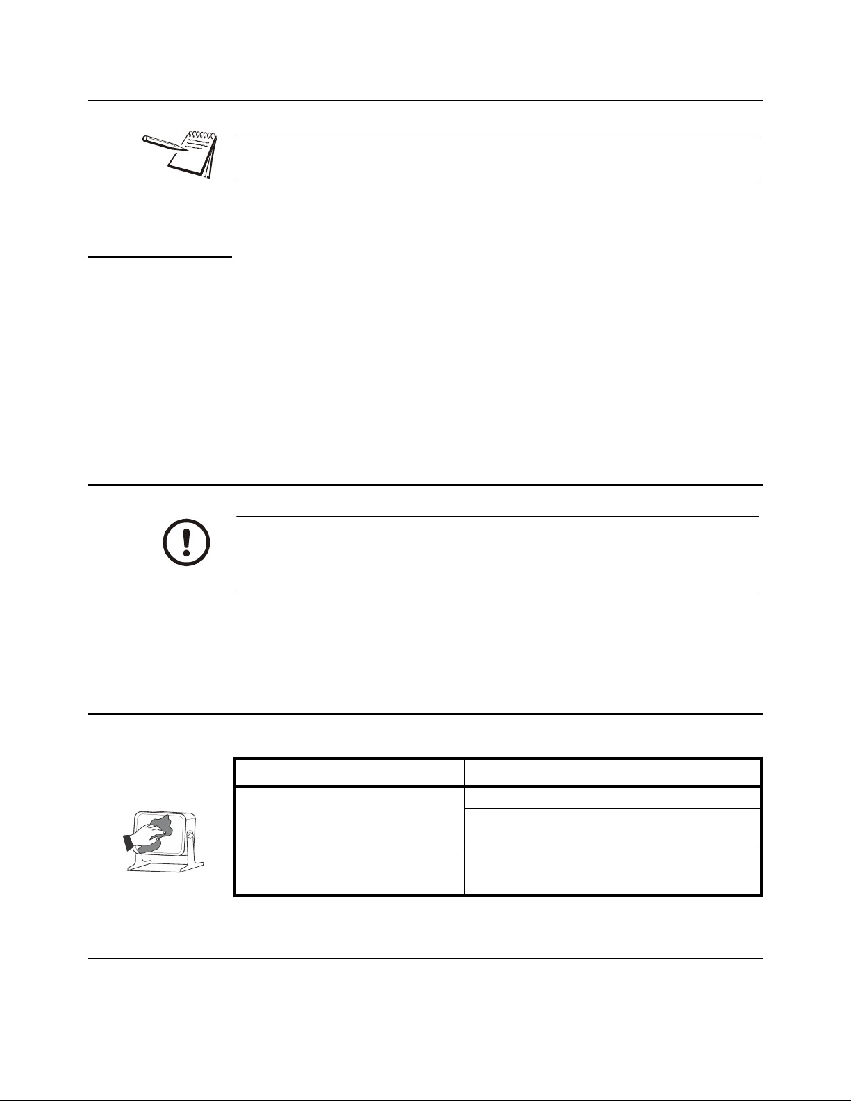
1.4 Cleaning the machine
Table 1.1 Cleaning DOs and DON’Ts
DO DO NOT
Wipe down the outside of standard products
with a clean cloth, moistened with water and
a small amount of mild detergent
Spray the cloth when using a proprietary
cleaning fluid
Attempt to clean the inside of the machine
Use harsh abrasives, solvents, scouring cleaners or
alkaline cleaning solutions
Spray any liquid directly on to the display windows
1.5 Training
Do not attempt to operate or complete any procedure on a machine unless you have
received the appropriate training or read the instruction books.
8 ZK830 Counting Scale Service Manual
Page 9

1.6 Sharp objects
T o avoid the ri sk of RSI (Repetitive S train Injury), place the machine on a surface which
is ergonomically satisfactory to the user. T ake frequent br eaks during prolonged usage.
1.6 Sharp objects
Do not use sharp objects such as screwdrivers to operate the keys.
1.7 FCC and EMC declarations of compliance
United States
This equipment has been tested and found to comply with the limits for a Class A digital device, pursuant to Part 15 of the FCC Rules.
These limits are designed to provide reasonable protection against harmful interference when the equipment is operated in a
commercial environment. This equipment generates, uses, and can radiate radio frequency energy and, if not installed and used in
accordance with the instruction manual, may cause harmful interference to radio communications. Operation of this equipment in a
residential area is likely to cause harmful interference in which case the user will be required to correct the interference at his own
expense.
Canada
This digital apparatus does not exceed the Class A limits for radio noise emissions from digital apparatus set out in the Radio
Interference Regulations of the Canadian Department of Communications.
Le présent appareil numérique n’émet pas de bruits radioélectriques dépassant les limites applicables aux appareils numériques de
la Classe A prescrites dans le Règlement sur le brouillage radioélectrique edicté par le ministère des Communications du Canada.
European Countries
WARNING: This is a Class A product. In a domestic environment, this product may cause radio interference in which the user may be
required to take adequate measures.
ZK830 Counting Scale Service Manual 9
Page 10
2 Introduction
lb
kg
GROSS
NET
TARE
PRINT
SP PCW T%TOTAL
g
COUNT
HI RES
ZK830
THE CO UNT IN G
FEATURE IS NO T L EGAL
FOR T RA DE
TARE SELECT UNITSPRINT
SAMPLE
ZERO
F1
SCALE
F2
PLU
PCWT
F3
F4
PT
12
1
23
4
56
7
89
C
0
.
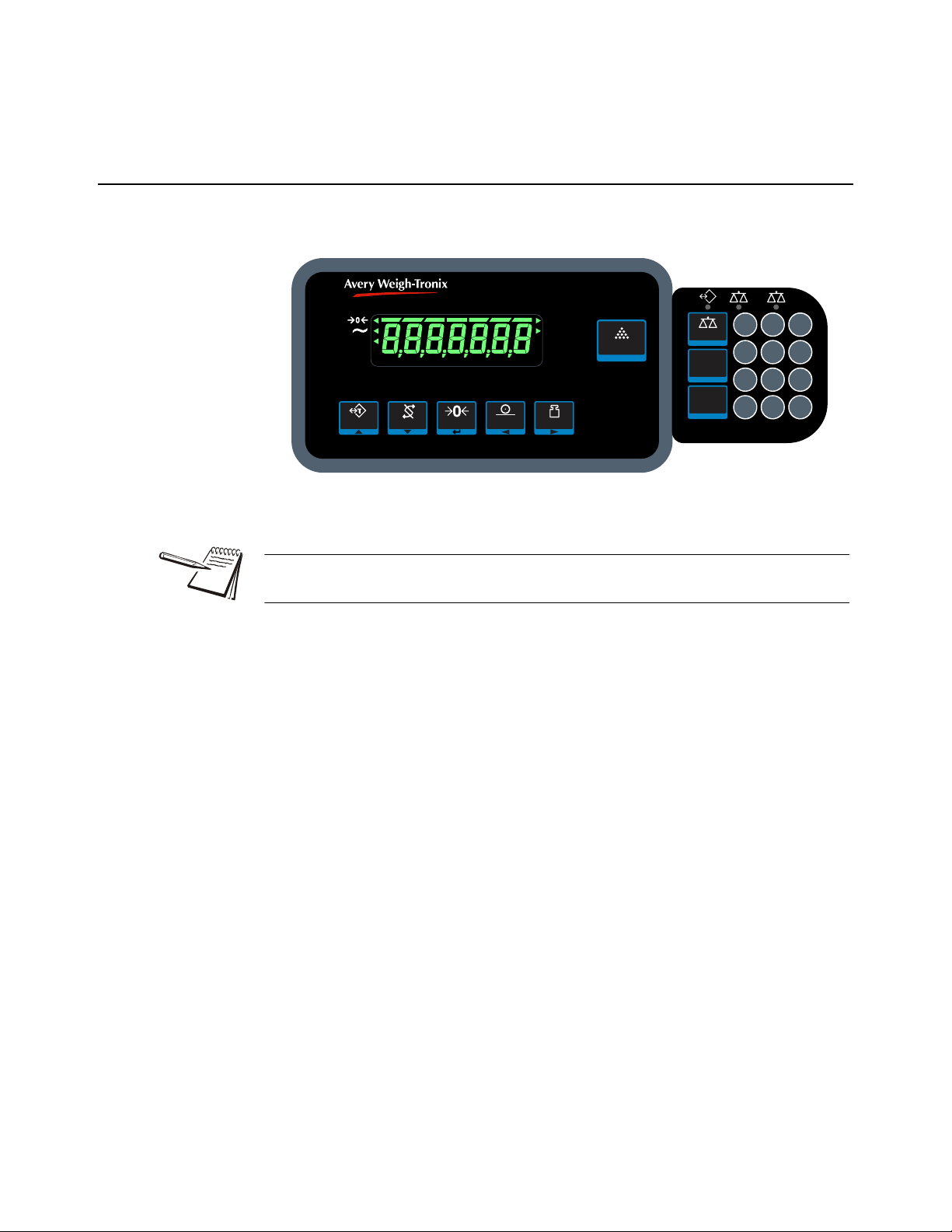
2.1 Front panel
The front panels for the ZK830 main display and optiona l ke ypad are shown in Figure
2.1 and consists of the keys and the display.
Figure 2.1 Front panel with optional keypad
Never press a key with anything but your finger. Damage to the overlay may result if
sharp or rough objects are used.
See the price list for option kits available for the ZK830. Installation instructions are
included in each kit.
ZK830 Counting Scale Service Manual 10
Page 11

2.1 Front panel
TAR E
SELECT
ZERO
PRINT
UNITS
SAMPLE
F1
SCALE
F2
PLU
PCWT
F4
1
23
4
56
789
C0
.
The normal function of the keys on the front panel of the ZK830 are listed below.
Press the TAR E key to perform a tare function.
With no weight on the scale, press the TAR E key to clear a tare value.
Acts as an up arrow key for menu navigation.
Allows you to access minus and comma signs.
Acts as an ABORT key during the sampling process.
Press the SELECT key to toggle between the active display values.
Press and hold to enter the setpoint editor in all applications.
Acts as a down arrow key for menu navigation.
Allows you to access minus and comma signs.
Press the ZERO key to zero the display.
Acts as an ENTER key to accept a displayed value or function.
Press the PRINT to send information to a peripheral device through a configured
communications port. Press and hold the PRINT key to print accumulated totals, if
enabled.
Acts as a left arrow key for menu navigation.
Press the UNITS key to scroll through the available units of measure while in normal
operating mode.
Acts as a right arrow key for menu navigation.
Press the SAMPLE key to select application specific choices.
Aborts a numeric entry and acts as an ESCAPE key in the menu navigation.
Also used to display or enter an accumulator channel.
Press and hold to view the password entry screen for menu access.
Keys on the optional keypad shown below:
Press the SCALE key to switch between two attached scales.
Press the PLU key to access the PLU list. In the counting application this key can be
used to update pieceweight and/or tare weight if enabled. With an active PLU, press
the PLU key three times to update pieceweight and tare weight.
Press the PCWT key to enter a known piece weight.
If enabled, allows the user to see a high resolution weight value.
In the count application allows you to enter or view piece weight values.
Use the numeric keypad to enter values or clear a value from the display (C key).
ZK830 Counting Scale Service Manual 11
Page 12
2 Introduction
lb
kg
GROSS
NET
TARE
0
g
COUNT
HI RES
PRINT SP % PCWT TOTAL
center-of-zero
motion
battery status
setpoints
print
bargraph
Net weight
Tare weight
pieceweight
Gross weight
percent
total
count
high resolution
Unit of
measure
Ethernet
connection
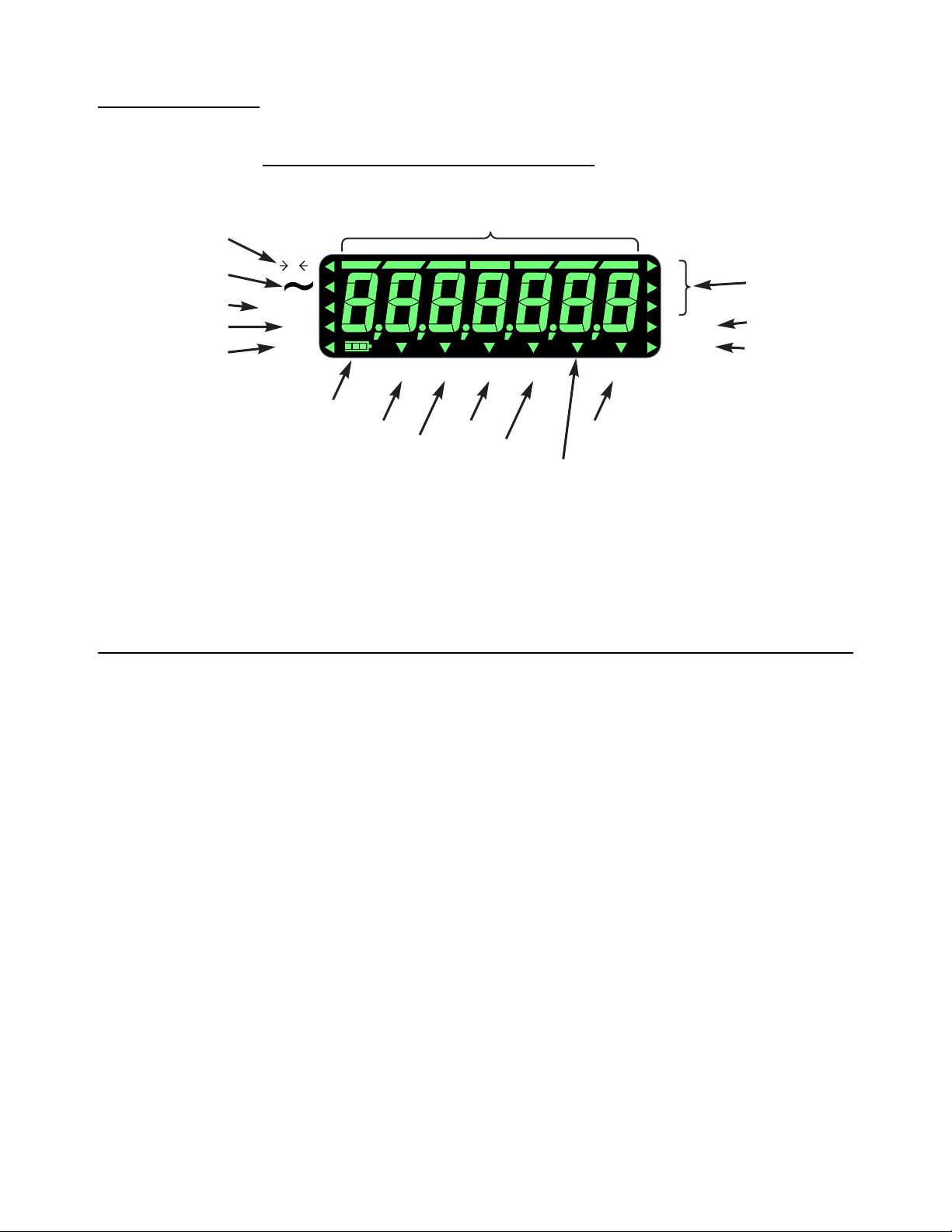
2.1.1 Front Display
Annunciators
The display annunciators are defined in Figure 2.2.
2.2 Powering up the ZK830
Figure 2.2 Display annunciators
The triangular annunciators will light during operation to inform the user of the weighing
mode, active unit of measure, etc.
The ZK830/BSQ comes with a base mounted AC power supply un it (PSU) conn ected
to the back of the BSQ. This supplies the required input power of 12 to 36 VDC @
200ma minimum and is connected to a properly grounded outl et (100 VAC - 240 VAC,
50 or 60 Hz). The indicator is always ON as long as power is received.
If using the optional rechargeable battery pack mounted on the rear of the base you
can expect 16 hours of operation between charges. Recharge time is four hours using
the in-line PSU. The battery pack requires 24 to 36V to charge. The battery timer
setting can be used to turn the indicator display OFF automatically.
The ZQ-BA T can a lso be use when using the optional column. This battery can la st up
to 25 hours of continuous use or one to two weeks of occasional operation.
You can also power the indicator with a 12 to 36 VDC power su pply (15 0ma minimu m
at 24VDC) via a 2.1mm center positive barrel jack plugged into the receiver on the back
of the indicator.
12 ZK830 Counting Scale Service Manual
Page 13
2.3 Numeric entry procedure (without optional keypad)
These segments flash in alphanumeric entry mod e
Press to increment the flashing number
Press to decrement the flashing number
Press to backspace cursor in a number
Press to advance cursor in a number
Press to accept a value
Press to escape an entry screen
TARE /
-
SELECT /
-
PRINT /
-
UNITS /
-
ZERO /
-
F1 /
ESC -
2.3 Numeric entry procedure (without optional keypad)
The keys in Figure 2.3 have alternate functions in numeric entry screens.
Figure 2.3 Key function during numeric entry
In numeric entry screens, the center segments shown in Figure 2.3 flash. Use the keys,
as described in Figure 2.3, to enter a value on the display. Following is an example:
Example: To key in the number 507:
Repeatedly press the TARE() or SELECT() key until 5 appears on the display.
Press the UNITS() key once to move cursor one space to the right.
Repeatedly press the TARE() or SELECT() key until 0 appears on the display.
Press the UNITS() key once to move cursor one space to the right.
Repeatedly press the TARE() or SELECT() key until 7 appears on the display.
Press the ZERO key to enter or accept the value.
Press the PRINT() key to move the entry function one digit to the left. This effectively
deletes the current value in that position and allows you to enter a new value in that
position.
2.4 Numeric entry procedure (with optional keypad)
Use the optional numeric keypad to input all numbers. Press the ZERO key to enter or
accept the value.
ZK830 Counting Scale Service Manual 13
Page 14
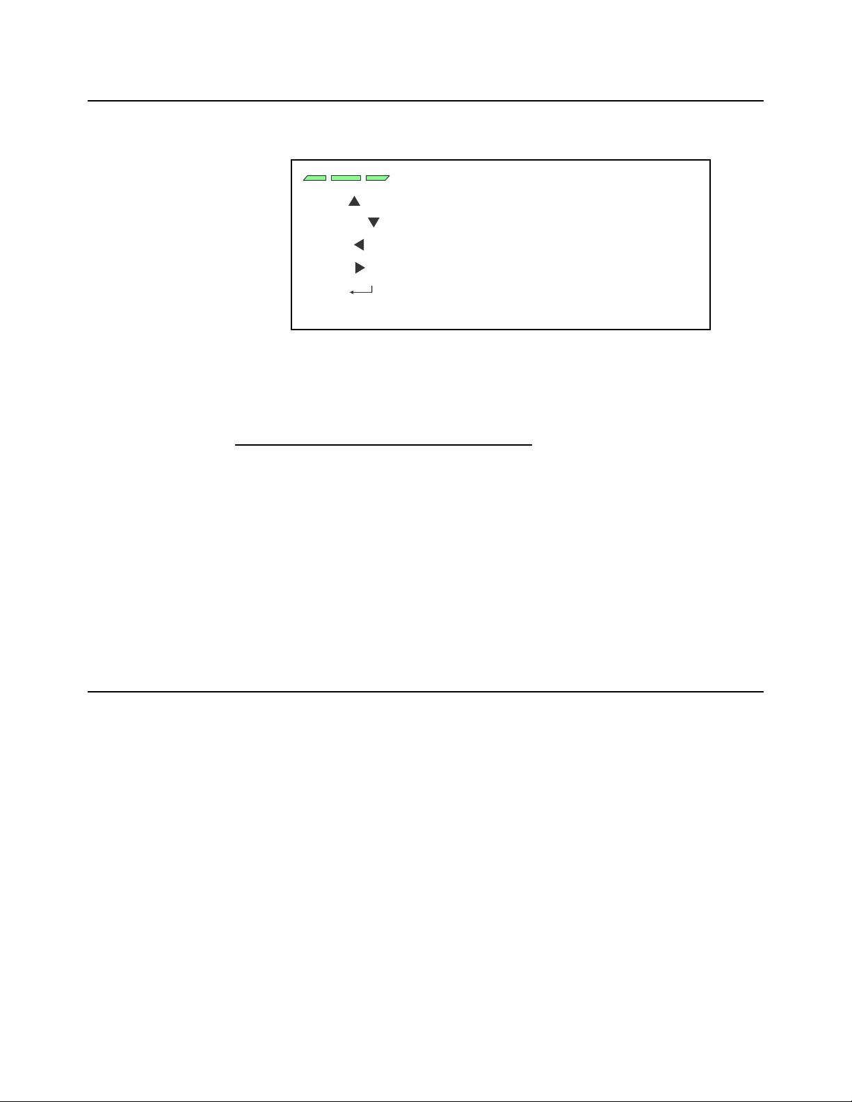
3 Introduction to the menus
Press SELECT/ to move down in a menu
Press TARE/ to move up in a menu, except at the
bottom item in a menu, then use ZERO/ or F1
Press PRINT/ to move left in a menu
Press UNITS/ to move right in a menu
Press ZERO/ to accept a value or choice and
move up in the menu.
Press F1 to escape and move up in the menu
Menus, accessed through passwords, are available in the indicator to customize and
configure the indicator for your purposes. The menu levels and their passwords are
shown below:
Password Menu Level Accessed Menus
111 USER User, About, Audit
3570 DIAGNOSTICS Diag, User, About, Audit
3088 ADMIN Setup, Diag, User, About, Audit
2580 CALIBRATE Calib
1793 SUPER Application specific items. See User manual.
The CALIBRATE menu level accesses the calibration procedure only. You can also
access the calibration menu through the Setup menu using the ADMIN password.
Some menus appear in more than one menu level. As you can see in the ta ble above,
the 111 password gives you access to three menus; User, About and Audit. The 3570
password gives you access to those three plus the Diagnostics menu. The 3088
password gives you access to those four plus the Setup menu.
This allows the supervisor to control access to some or all of the menus b ased on the
passwords shared. The menus are the same no matter which menu level you access
them from.
The menus are always explained in a sequential manner to cover all information in a
logical fashion. You will probably never access all the menu items in this manner . You
can navigate to the area of the menu that needs to be changed by using the menu
maps and key navigation legends which are inserted as a reminder with most menus.
See Numeric entry procedure (without optional keypad) on page 13 for instructions on
how to enter a password to get to the menus. Key functions in the menu s ar e sh own
below.
Menu Navigation Keys:
ZK830 Counting Scale Service Manual 14
Page 15
3.1 Accessing the menus
Press SELECT/ to move down in a menu
Press TARE/ to move up in a menu, except at the
bottom item in a menu, then use ZERO/ or F1
Press PRINT/ to move left in a menu
Press UNITS/ to move right in a menu
Press ZERO/ to accept a value or choice and
move up in the menu.
Press F1 to escape and move up in the menu
Follow these steps to access the various menus in the indicator.
1. With the indicator powered up and in normal operating mode, press and hold
the SAMPLE/F1 key …
Pass is briefly displayed, then a flashing 0, prompting you to enter the
password.
When the 0 is flashing, press F1 and the application name is briefly displayed, then
the indicator returns to normal operating mode.
2. Key in the p assword for the menu you want to access and press the ZERO key
to accept it …
The first item in the top level of the menu you accessed is displayed.
3. Use the navigation keys, shown below, to navigate through the menu
structure. The symbols appear on the bottom of the keys.
3.1 Accessing the menus
Menu Navigation Keys:
3.2 Exiting the menus
1. If you are at the bottom item in a menu use ZERO to accept a choice or value
and move up a level, or use F1 to escape and move up one level without
accepting the choice or value. From that point, press the TARE key repeatedly
until …
SAVE no is displayed. This means “Do not save changes. “
2. Use the PRINT or UNITS key to scroll through the choices: SAVE no,
SAVEYES and CAnCEL. Press ZERO to accept the displayed choice.
If you choose SAVE no or SAVEYES the indicator exits the menu and
ZK830 Counting Scale Service Manual 15
If you choose CAnCEL, the indicator remains in the menu.
returns to normal weighing mode.
OR
Page 16

3 Introduction to the menus
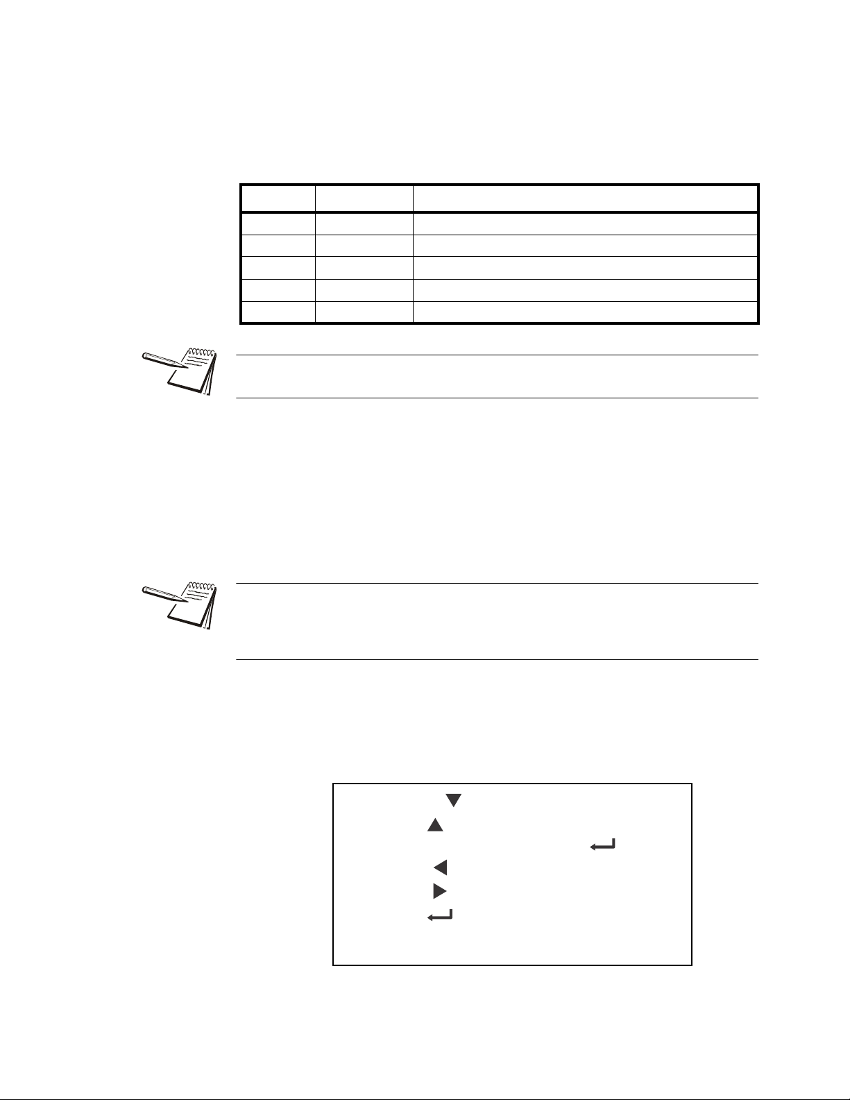
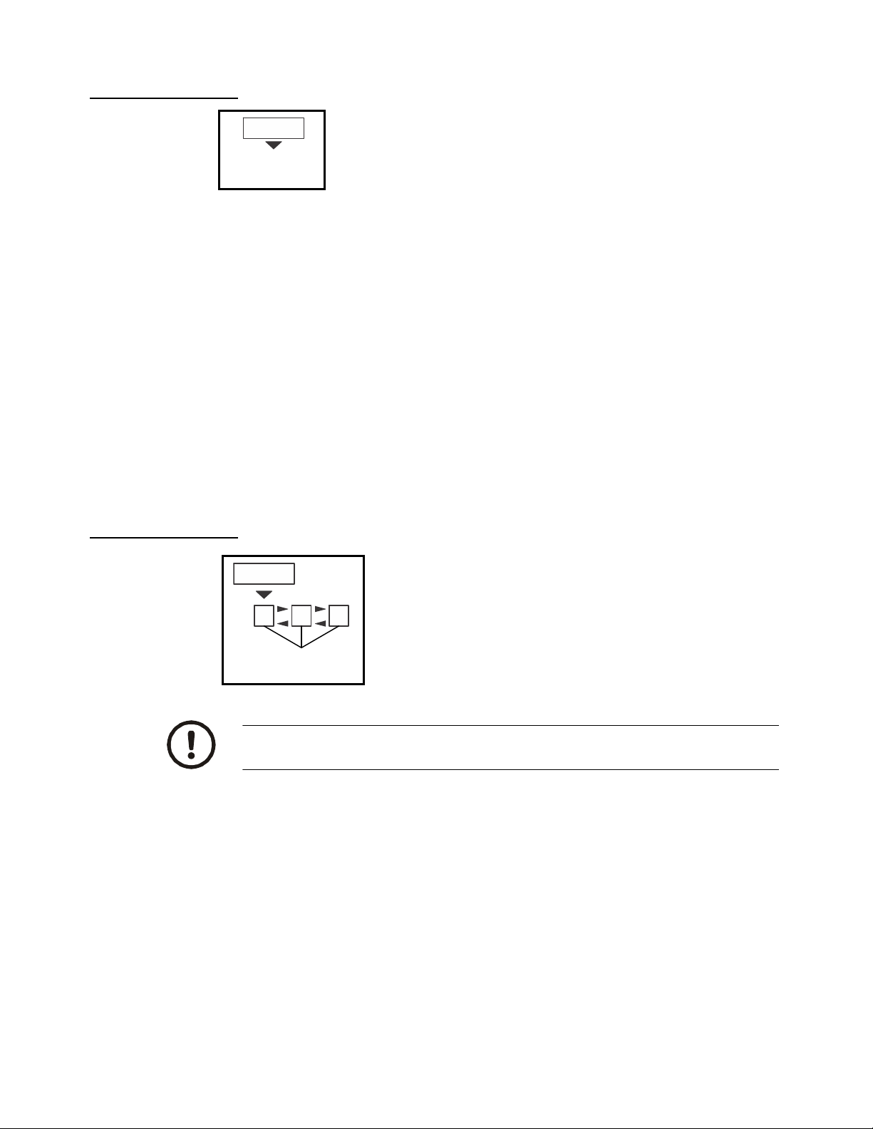
3.3 Menu annunciators
The menu structure is made up of menu items, parameters, value entry screens and
lists from which you choose one item. To help you know where you are in the menu,
the bar graph at the top of the display is on while the indicator is in the menus and will
change appearance according to the following rules:
All segments flashing This means you are in the menu structure but not
Center flashing / others off This means you are in a numeric entry screen.
Right flashing / others off This means you are in a list. Scroll through the
in any of the following screens.
Enter a number and press ZERO to accept.
choices with the PRINT and UNITS keys and
press ZERO to accept.
Left flashing / others off This means you are in a data entry.
Every alternate segment flashing This means you are in octet entry for IP, Subnet
or Gateway address.
16 ZK830 Counting Scale Service Manual
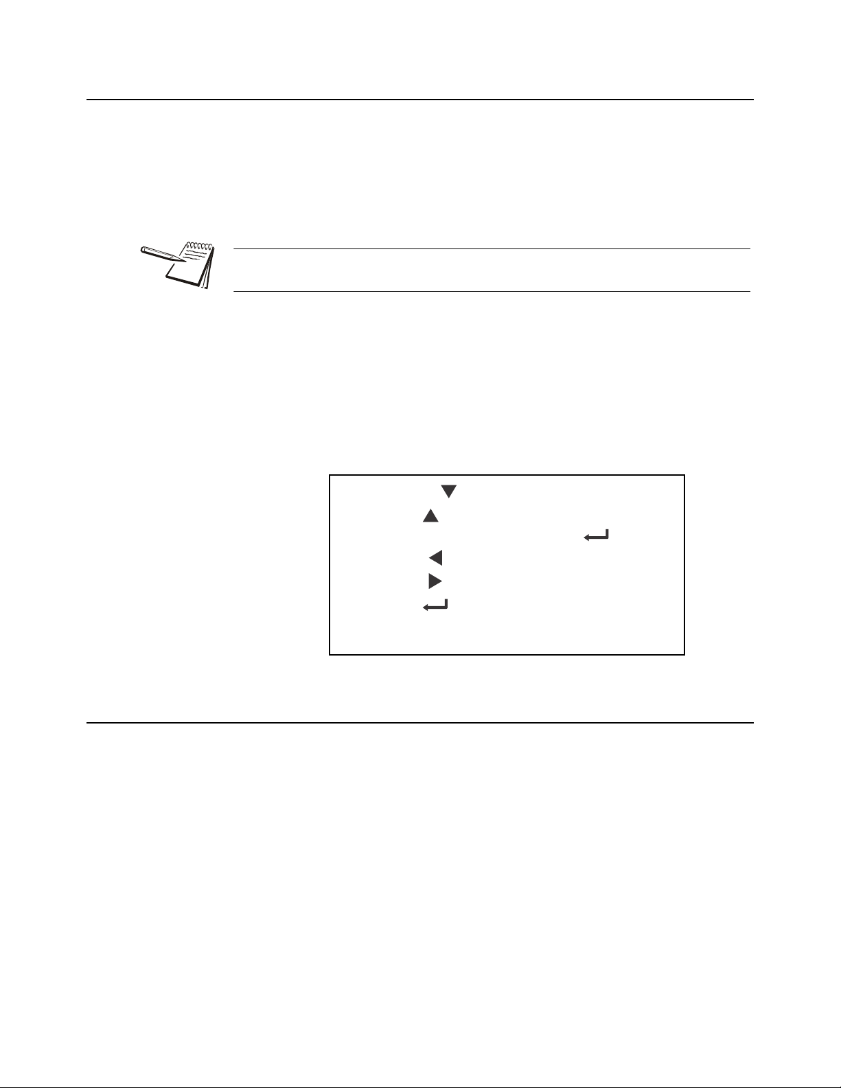
Page 17
4 User level menus
See
page 17
See
page 20
See
page 24
User About Audit
User
Site ID
Seal
Enter
Site ID
View Seal
Status
Time
Date
Set
12hr 12hr-AP 24hr
Set
Style
MMDD4YMMDD2Y DDMM2Y DDMM4Yy- x
m- x
d- x
Style
h- x
m- x
s- x
Reference
Numeric entry procedure
(without optional keypad)
on page 13
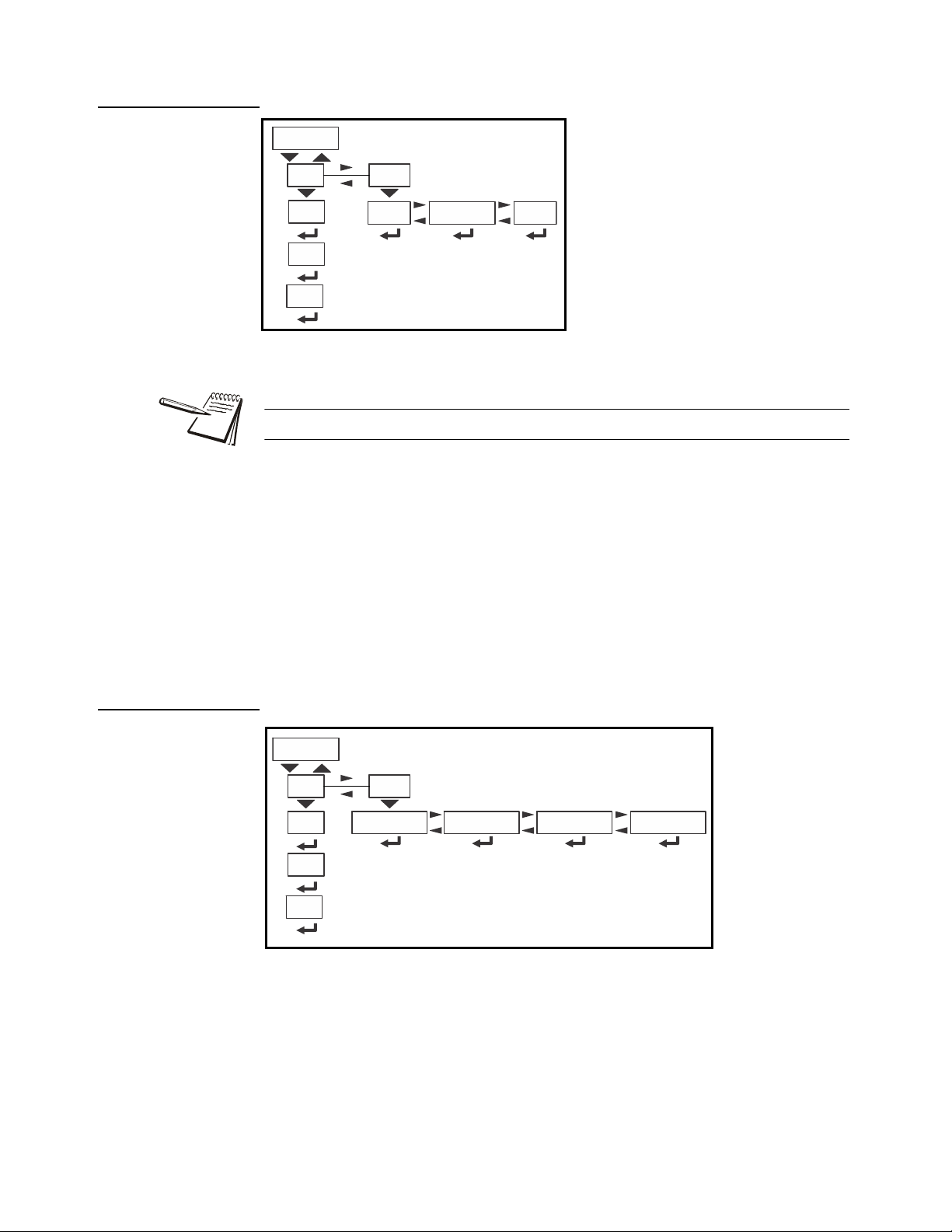
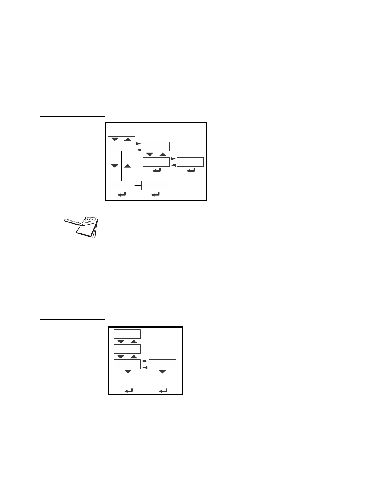
The USER level (password 111) contains the User, About, and Audit menus arranged
as shown in Figure 4.1.
Figure 4.1 USER level (password 111) menus
To access the USER level, from normal weighing mode, press and hold the SAMPLE/
F1 key. Enter password 111 and press the ZERO key.
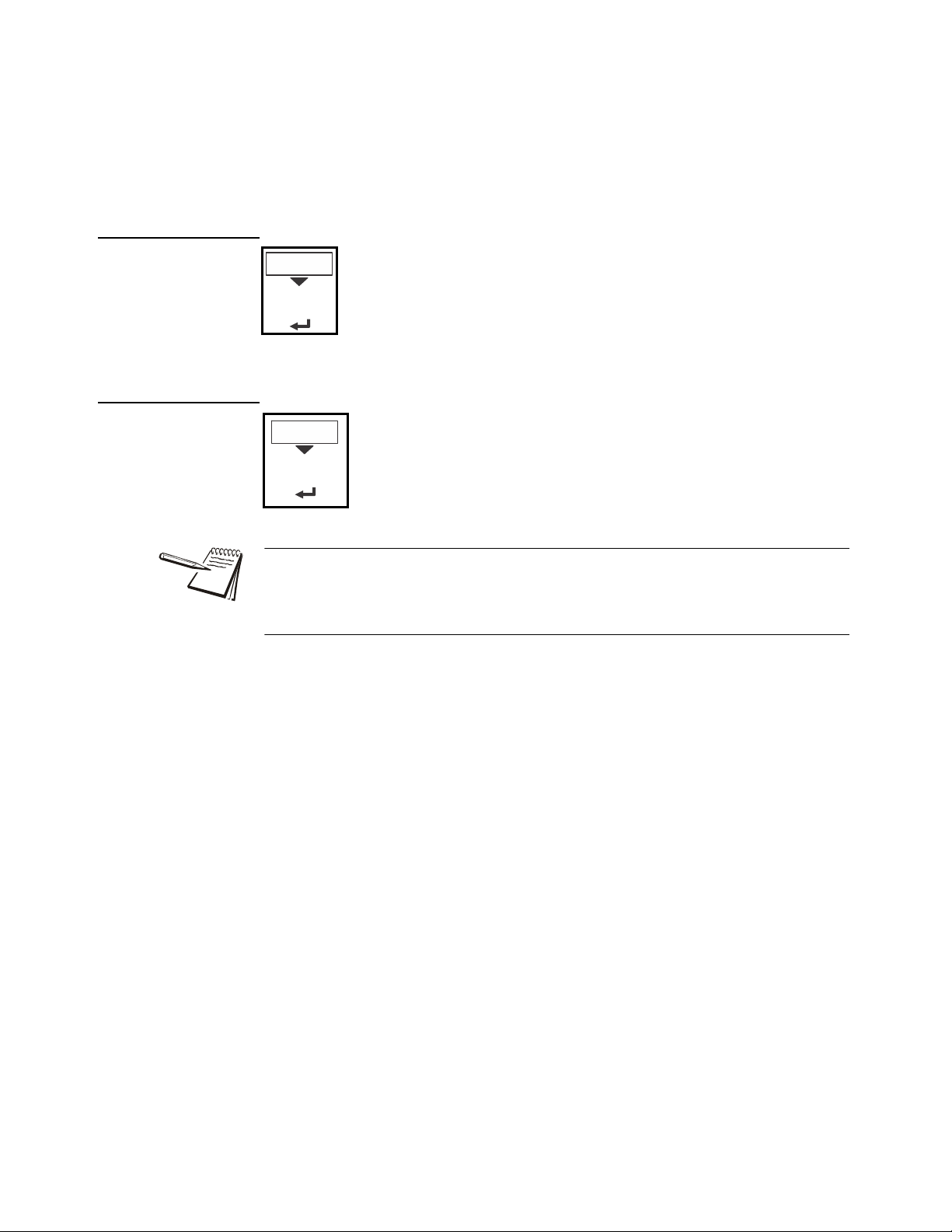
4.1 User menu
The User menu is shown in Figure 4.2.
4.1 User menu
ZK830 Counting Scale Service Manual 17
Figure 4.2 User menu
Use this menu to set the time, date, site ID, to see the physical seal status and print
archive information. Each is explained below:
Page 18
4 User level menus
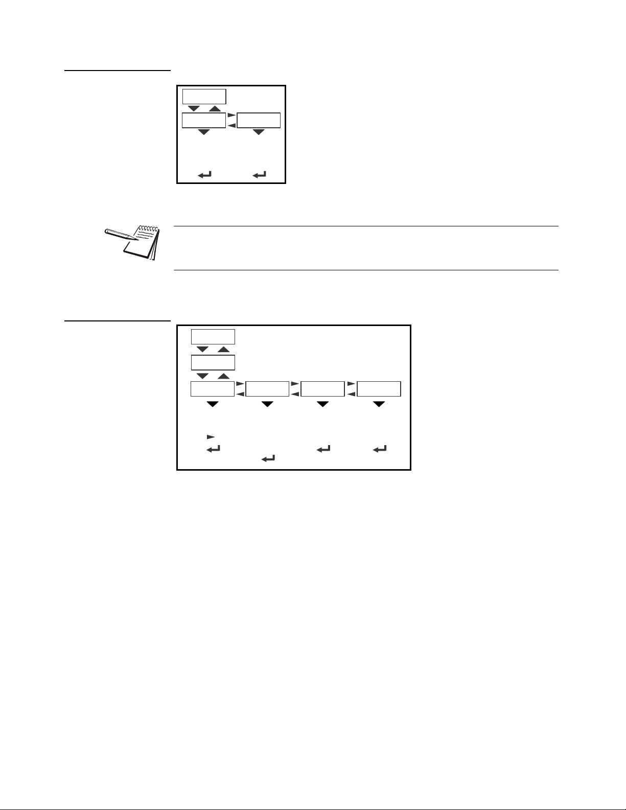
Use the tiME menu item to set the clock
(SEt) and to choose the style of the time
display (StYLE) 12 hr, 12 hr AM/PM or
24 hr.
Time
Set
12hr 12hr-AP 24hr
Style
h- x
m- x
s- x
Date
Set
Style
MMDD4YMMDD2Y DDMM2Y DDMM4Yy- x
m- x
d- x
4.1.1 Time
The Time and Date can be used in print formats.
SEt Use this to enter values for the time.
h- x, = Hour
m- x = Minute
s- x = Seconds
4.1.2 Date
StYLE Choose the style of the time display. Choices are:
12hr, = 12 hour clock
12hr-AP = 12 hour clock with AM/PM
24hr = 24 hour military time
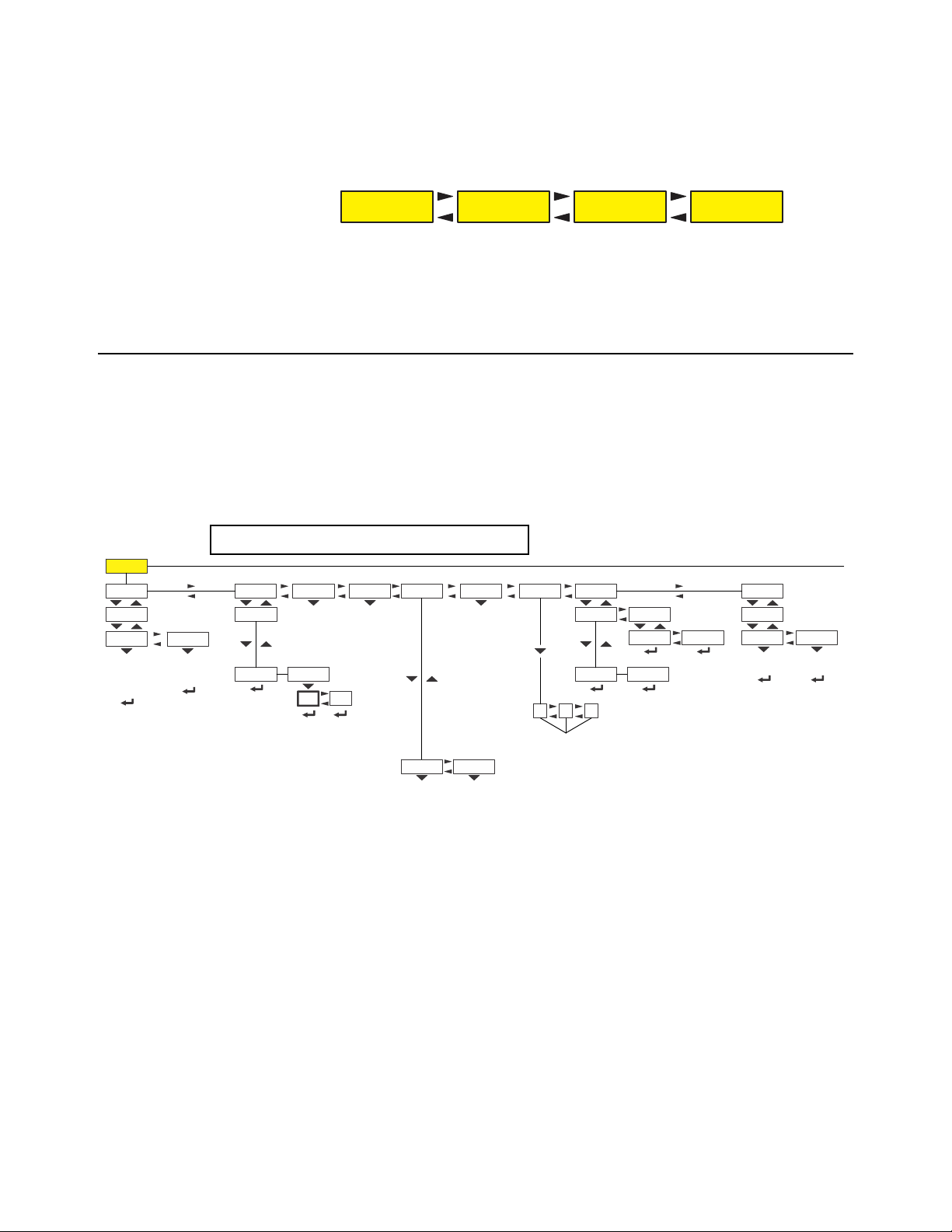
Use the dAtE item to set the year, month and day and the style of the displayed date.
SEt Enter values for the date.
y- x = Year
m- x = Month
d- x = Day
18 ZK830 Counting Scale Service Manual
Page 19
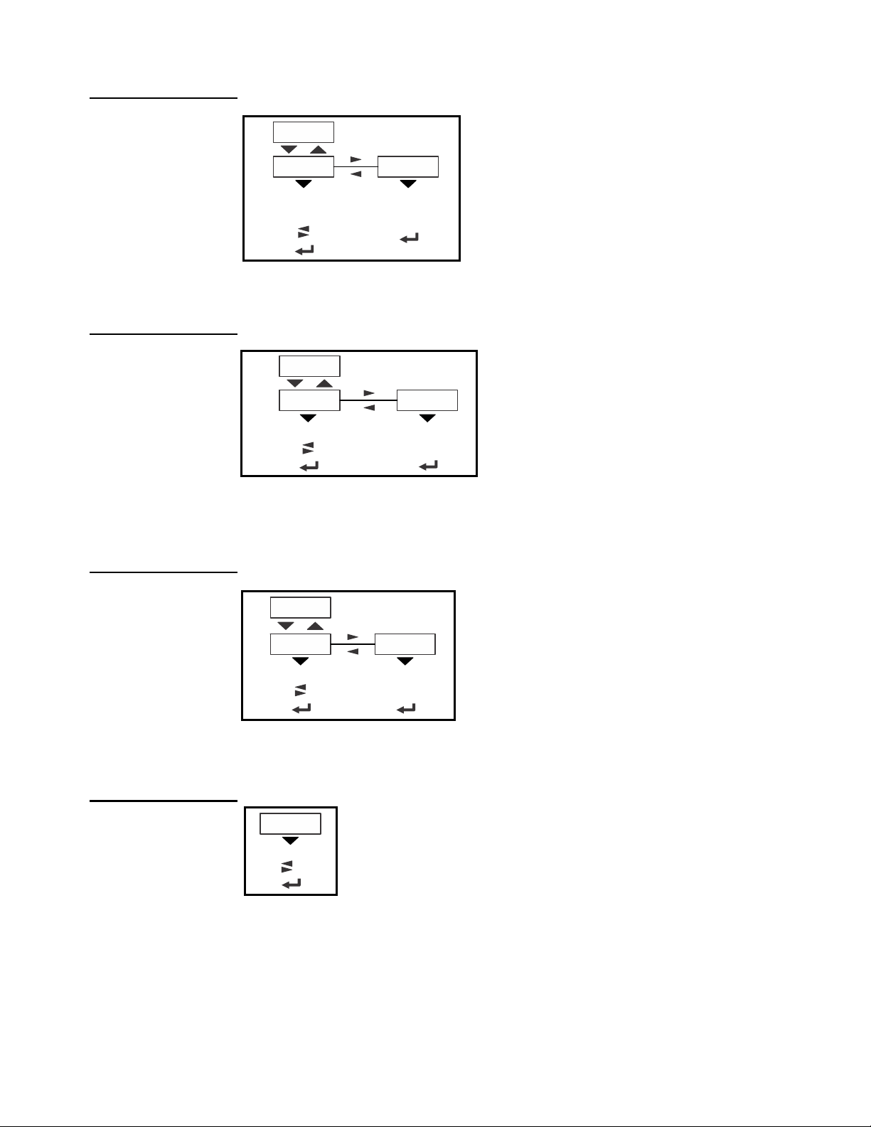
4.1.3 Site ID
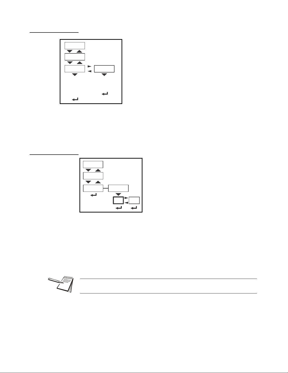
SitE Use this to enter a Site ID.
The Site ID can be used in a print format. Use the
alphanumeric entry methods described in 2.3 to enter a
Site ID. (maximum 6 digits)
Site ID
Enter
Site ID
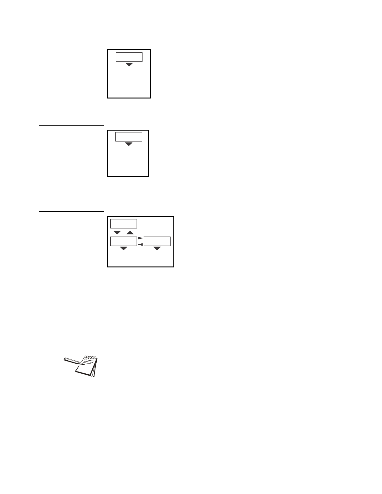
SEAL Use this to view the seal status of the indicator.
This is the status of the physical seal jumper inside the
indicator. If the unit is sealed, no changes can be made to
the configuration of the indicator. See the note below.
Seal
View Seal
Status
4.1.4 Seal
4.1 User menu
StYLE Choose the style of the date display. Choices are:
MMdd2Y = Month, Day, 2-digit Year
MMdd4Y = Month, Day, 4-digit Year
ddMM2Y = Day, Month, 2-digit Year
ddMM4Y = Day, Month, 4-digit Year
The seal switch jumper, P7, is located near the bottom center of the ma in PCB. See
jumper settings in chapter 13. If the jumper is installed, the indicator is sealed. This
means the only the Diagnostic, User, About, Audit and Supervisor menus can be
accessed. Other menus cannot be accessed - the display will flash SEALEd.
To exit the menu, see Exiting the menus on page 15.
ZK830 Counting Scale Service Manual 19
Page 20

4 User level menus
BSQ
Sw Part
Version
Cur. Ser
xxxx
xxxxx
(View
software PN)
(View
software
version)
xxxx
(View
cell SN)
xxxxxx
Serial
About
App.
EnetFirmBoot
VersionPartno
IP
GatewaySubnet
VersionPartno
(View
bootloader PN)
VersionPartno
(View version)
Mac
1 xx
2 xx
3 xx
4 xx
5 xx
6 xx
1 xx
2 xx
3 xx
4 xx
1 xx
2 xx
3 xx
4 xx
1 xx
2 xx
3 xx
4 xx
(View SN)
xxxx
xxxxx
Dload
Sserial Dserial
(View
license
number)
(View
license
number)
(View App PN)
AWT30
XXXXX
(View version)
X.X.X.XX
(View Firmware PN)
AWT30 XXXXX
(View version)
X.X.X.XX
AWT30
XXXXX
X.X.X.XX
Scale X
Cal. Ser
(View SN of
calibrated
cell)
Reference Numeric entry procedure (without
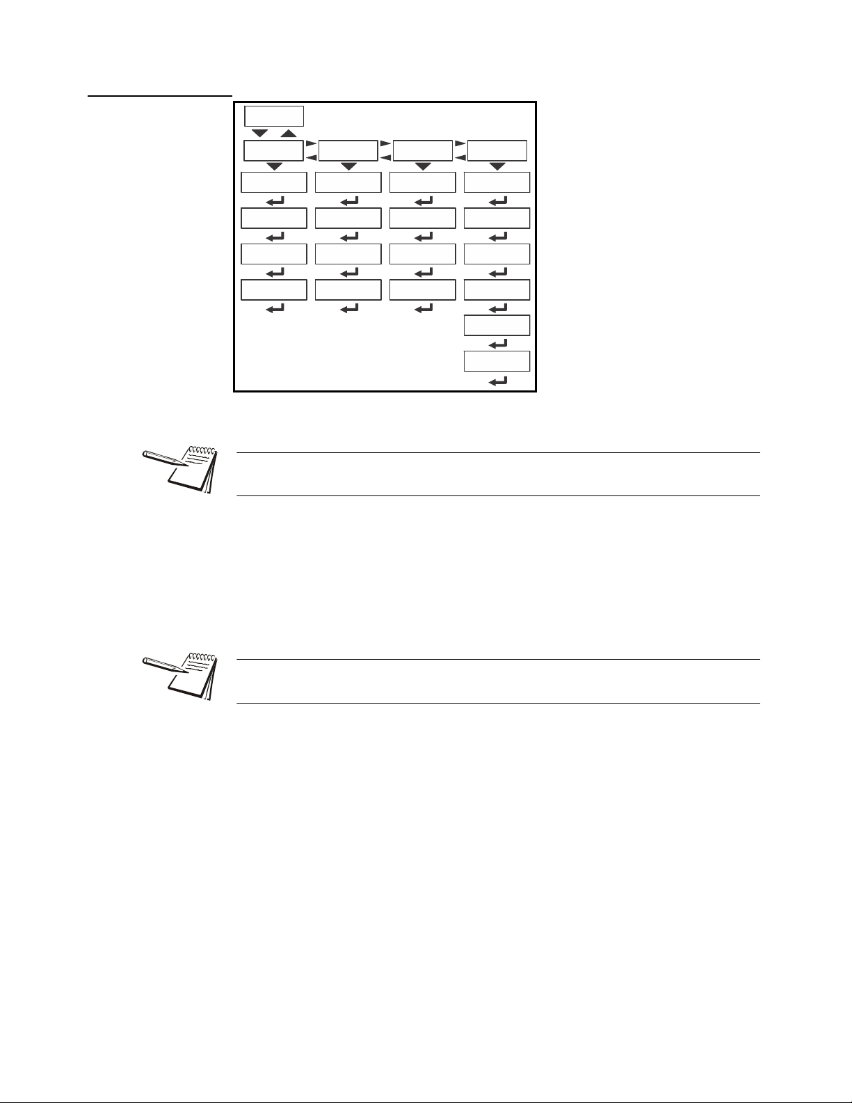
4.2 About menu
The About menu is shown in Figure 4.3.
Figure 4.3 About menu
Use this menu to display information about the various items shown in Figure 4.3. Each
is explained below:
Definitions:
Bootloader Software that makes the electronics run.
Firmware Embedded system software that creates core functions of the product.
App Specific software that controls the behaviour for a given installation.
20 ZK830 Counting Scale Service Manual
Page 21
4.2.1 Boot (Bootloader)
PArtno Use this to view the bootloader part
number. The part number is
displayed in two parts. Press RIGHT
arrow key or LEFT arrow key to
toggle the display between the first
and second parts of the part number.
VErSion Use this to view the version of the
bootloader.
Boot
(View
bootloader PN)
VersionPartno
(View version)
AWT30 XXXXX
X.X.X.XX
PArtno Use this to view the firmware part
number. The part number is
displayed in two parts. Press
RIGHT arrow key or LEFT arrow
key to toggle the display between
the first and second parts of the
part number.
VErSion Use this to view the version of the
firmware.
Firm
VersionPartno
(View Firmware PN)
AWT30
XXXXX
(View version)
X.X.X.XX
PArtno Use this to view the App part number.
The part number is displayed in two
parts. Press RIGHT arrow key or
LEFT arrow key to toggle the display
between the first and second parts of
the part number.
VErSion Use this to view the version of the
App.
App.
VersionPartno
(View App PN)
AWT30 XXXXX
(View version)
X.X.X.XX
SEriAL Use this to view the Serial Number of the indicator . The
number is displayed in two parts. Press RIGHT arrow
key or LEFT arrow key to toggle the display between the
first and second parts of the serial number.
Serial
(View SN)
xxxx
xxxxx
4.2.2 Firmware
4.2 About menu
4.2.3 App
4.2.4 Serial
ZK830 Counting Scale Service Manual 21
Page 22
4 User level menus
Enet
IP
GatewaySubnet Mac
1 xx
2 xx
3 xx
4 xx
5 xx
6 xx
1 xx
2 xx
3 xx
4 xx
1 xx
2 xx
3 xx
4 xx
1 xx
2 xx
3 xx
4 xx
4.2.5 Enet
EnEt This stands for Ethernet. Use this to view the network addresses.
If the indicator is connected to an Ethernet network, the values displayed will be the
current assigned addresses.
iP Use this to view the IP address.
SubnEt Use this to view the Subnet address.
gAtEWAY Use this to view the Gateway address.
MAc Use this to view the Mac address.
The IP, Subnet and Gateway addresses are a series of four double digit values.
The MAC address is a series of six double digit values: 1 XX, 2 XX, 3 XX, etc.
22 ZK830 Counting Scale Service Manual
Page 23
4.2.6 Download
dLoAd This stands for download. Use this to view
these items:
SSEriAL View the license number that
created the configuration file.
dSEriAL View the license number that
downloaded the configuration
file.
This is used for security and licensing purposes.
Dload
Sserial
Dserial
(View
license
number)
(View
license
number)
BSQ
Sw Part Version Cur. Ser
xxxx xxxxx
(View
software PN)
(View
software
version)
xxxx
(View
cell SN)
xxxxxx
Scale X
Cal. Ser
(View SN of
calibrated
cell)
4.2.7 BSQ
4.2 About menu
To upload a configuration file, the license number of the Configurator (Ztools)
software must match one of the license numbers in the indicator Contact AWTX
Technical Support for assistance.
ZK830 Counting Scale Service Manual 23
This stands for Bench Scale - Quartzell.
SW PArt View the software part number of the ce ll that is connected.
VErSion View the software version of the cell that is connected.
cur.SEr View the serial number of the cell that is connected.
cAL.SEr View the serial number of the cell that was connected at the time of
calibration.
To exit the menu, see Exiting the menus on page 15.
Page 24

4 User level menus
Counter
Config
Displays
number of
configurations
Audit
Calib
Displays
number of
calibrations
countEr Use this to view these items:
conFig View how many times the
indicator has been
configured.
cALib View how many times the
indicator has been
calibrated.
Counter
Config
Displays
number of
configurations
Calib
Displays
number of
calibrations
4.3 Audit menu
Use this menu to display audit counters for configuration and calibration.
4.3.1 Counter
Figure 4.4 Audit menu
To exit the menu, see Exiting the menus on page 15.
24 ZK830 Counting Scale Service Manual
Page 25
5 Diagnostics level menus
See page 17 See page 20 See page 24See page 25
Diag User About Audit
Reference Numeric entry procedure (without
Diag
Buttons
Display
Scale
Test button
function
( exits
ZERO
the test)
Continuous
display test
( exits
ZERO
the test)
ScaleX
View scale
output in
A to D or
mV/V
Cur.Zero
ScaleX
Value Clear
Ports
Serial1 Serial2
Loopback
test
Loopback
test
Tension
Compres
Tension
frequency
Compression
frequency
Logs
Print
Clear
Serial 1 Serial 2
Clr no
Clr yes
Inputs Outputs
Test configured
inputs
1 2
3
Toggles selected
output on or off
(Must be turned
ON in Outputs
menu)
BSQ
ScaleX
Counts
Std Dev
View standard
deviation for
last X seconds
no
YES
The DIAGNOSTICS level (password 3570) is the same as the USER level except it
adds the Diag menu. The DIAGNOSTICS level is shown in Figure 5.1.
Figure 5.1 DIAGNOSTICS level (password 3570) menus
5.1 Diag menu
Use the Diag menu to check or verify the performance of the ind icator. The diagnostic
tests available include: Scale A to D to view output from the connected scale base or
load device, the current zero offset from ca libration zero, a display segment test, a front
panel keypad or button test, serial Com port s and USB host port test, remote inputs and
outputs test, and an option card test if installed. You can print an error log report that
provides information on previous error conditions such as overloads or underloads.
The Diag menu is shown in Figure 5.2.
5.1 Diag menu
Each of the items in the Diag menu is explained below:
ZK830 Counting Scale Service Manual 25
Figure 5.2 Diag menu
Page 26
5 Diagnostics level menus
ScALE Select to view values for Scale 1 or Scale 2, if
installed.
countS Use this to view a number representing the A to
D counts. The value is only for diagnostic
purposes. The value should increase as weight
on the scale increases and decrease as weight
decreases.
Press
SELECT to toggle to a mV/V display.
This is an approximate value for the mV/V value
output by the loadcell. If the scale is a BSQ then
you can only view counts, not mV/V.
Std d Ev This stands for Standard Deviation. This gives
you the standard deviation of the counts for the
last, set number of seconds.
Scale
ScaleX
View scale
output in
A to D or
mV/V
Counts
Std Dev
View standard
deviation for
last X seconds
Cur.Zero
ScaleX
Value
Clear
no
YES
5.1.1 Scale
5.1.2 Current Zero
cur.ZEro This stands for current zero and represents the weight of fset between the
calibration zero setting and the current zero setting due to pushbutton zero
or Auto-Zero Tracking (AZT) adjustments.
Select to view values for Scale 1 or Scale 2, if installed.
VALuE View the zero offset.
cLEAr Clear the zero offset to return the indicator to calibration zero. C hoose no
YES.
or
This can restore the original calibration zero point if the ZERO key is accidently
pressed when a tank or vessel contains product that cannot be emptied.
26 ZK830 Counting Scale Service Manual
Page 27
5.1.3 Display
diSPLAY Use to test the segments of the display. Each digit
area lights up in progression and continues until you
press
ZERO.
Display
Continuous
display test
( exits
ZERO
the test)
buttonS Use to test the keys. When you begin the test tESting is
briefly displayed followed by dashes.
Press any key to test if it is functioning and its name or
value will be displayed.
Press
ZERO to stop the test.
Buttons
Test button
function
( exits
ZERO
the test)
Ports
Serial1 Serial2
Loopback
test
Loopback
test
5.1.4 Buttons
5.1 Diag menu
5.1.5 Ports
PortS Use this to do a loopback test for serial port 1 or 2 or to perform a write/
read test on the USB port.
SEriAL1 or 2 When you pick a serial port to test, tESting is briefly displayed and
PASS or FAiL, depending on if the send and receive lines are
then
jumpered (pass) or not (fail). Add a jumper or wire between the
transmit output and receive input. On an external 9 pin conn ector the
transmit line is pin 2 and the receive line is pin 3.
It is recommended that you insert the jumper (a paper clip works) into the external
cable connector to validate the wiring and not just the internal port s. See System
block diagram on page 114 for I/O configuration of the serial ports TB3.
ZK830 Counting Scale Service Manual 27
Page 28
5 Diagnostics level menus
inPutS The input test is used to verify if external switches wired
to the input ports on TB2 are functioning properly.
Follow the steps below to perform the inputs test.
Inputs
Test configured
inputs
outPutS The output test is used to verify if external relays or
lights (etc.) connected to TB2 are properly wired
and functioning properly.
Follow the steps below to perform the output test.
Outputs
1 2
3
Toggles selected
output on or off
5.1.6 Inputs
1. Press SELECT …
in 000 is displayed, if no inputs are jumpered.
2. To test input 1, jumper pins 1 and 2 of the I/O connector on the indicator …
5.1.7 Outputs
The first digit becomes
3. To test input 2, jumper pins 1 and 3 of the I/O connector on the indicator …
The second digit becomes
4. To test input 3, jumper pins 1 and 4 of the I/O connector on the indicator ….
The third digit becomes
5. Press
ZERO …
inPutS is displayed.
1 until the jumper is removed.
2 until the jumper is removed.
3 until the jumper is removed.
CAUTION: Be sure to take proper precautions to ensure material controlled by
the scale outputs will not create a hazardous condition during an output test.
1. WithoutPutS is displayed, press SELECT …
outPut1 is displayed.
2. Press
3. Press
28 ZK830 Counting Scale Service Manual
SELECT …
o.1-oFF is displayed.
PRINT or UNITS to toggle the output on (o.1-on) and repeat to turn it
oFF.
Output 1 will be toggled on and off as you press the keys. This is shown
by the annunciator (
SP1) on the display turning on and off.
Page 29
4. Press ZERO or F1 to stop the test …
Logs
Print Clear
Serial 1 Serial 2
Clr no
Clr yes
Tension
Compres
Tension
frequency
Compression
frequency
BSQ
ScaleX
outPut1 is displayed.
5.1 Diag menu
5.1.8 Logs
5. Press
6. When finished, press
The logs report will print any error conditions that may have occurred such as
overloads and underloads
UNITS to go to the next output. Repeat the steps to test output 2 and 3.
TARE …
outPutS is displayed.
5.1.9 BSQ
LogS These are logs of various functions. You can print or clear them from
memory.
Print Choose to print the log from Po rt 1 or Port 2.
cLEAR Choose to clear the log from memory.
bSQ The BSQ menu item provides the digital frequency information for the
crystals on the QDT (Quartzell Digital Transducer).
ScALE 1 or ScALE 2:
Select which Scale number the BSQ is assigned, ScALE 1 or
ScALE 2
ZK830 Counting Scale Service Manual 29
Page 30

5 Diagnostics level menus
coMPrSS This stands for compression frequency.
tEnSion This stands for tension frequency.
The nominal value for the tension and compression frequency is 47,200 ± 2000 kHz.
The tension and compression frequencies should each be as stable as the other and
within 10% of each other. As weight increases the tension frequency should increase
and the compression frequency should decrease.
This completes the Diag menu. To exit the menu, see
Exiting the menus on page 15.
30 ZK830 Counting Scale Service Manual
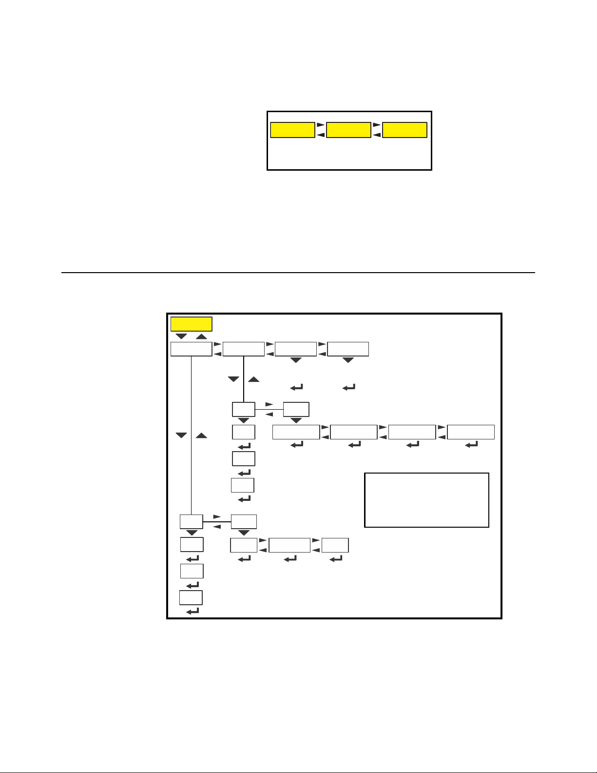
Page 31

6 ADMIN level menus
See page 17 See page 20 See page 24See page 25See page 31
Setup Diag User About Audit
See page 32 See page 38 See page 46 See page 54
Setup
Calib Scale System Ports
Input
Output
See page 60 See page 61
The ADMIN level (password 3088) is the same as the DIAG level except it adds the
Setup menu. The ADMIN level is shown in Figure 6.1.
6.1 Setup menu
In the Setup menu there are various submenus available to configure specific sections
of the scale operation. The top level items in the Setup menu are shown in Figure 6.2.
6.1 Setup menu
Figure 6.1 ADMIN level
Figure 6.2 Setup menu (password 3088)
Each of the items in the Setup menu are explained in the following sections.
ZK830 Counting Scale Service Manual 31
Page 32

6 ADMIN level menus
Calib
Span Linear Gravity
Pt2
G-fact
Lat
Alt
Calc
Display
Cal.Unit
LB
1000g
View
live weight
(F1 to stop)
Print
Port 1 Port 2
Calculates
gravity
factor
Enter
altitude
Enter
latitude
View or
enter
G-factor
Enter
Pt 2 test
weight
Live weight
displayed.
Place Pt 2
weight on
scale.
Live weight
displayed.
Pt3
Enter
Pt 3 test
weight
Live weight
displayed.
Place Pt 3
weight on
scale.
Live weight
displayed.
Pt4
Enter
Pt 4 test
weight
Live weight
displayed.
Place Pt 4
weight on
scale.
Live weight
displayed.
View or
enter new
span
Live weight
displayed.
Place span
weight on
scale.
Live weight
displayed.
Live weight
displayed.
Remove
all weight.
Live weight
displayed.
Zero
Cal.Zero
Scale 1 Scale 2
gram
Current
weight assigned
as temp
Cal. Zero
Temp
Last acquired
zero used
as
Cal. Zero
Last
Input
Zero
Span
Counts
mV
Counts
mV
6.2 Calibration Procedure
Use the Calib menu to perform Zero and Span calibration, add Linearity correction
points, manually input calibration para meters for Zero and Span, manually input
Gravitational correction values, view the live weight, set the calibration unit of measure
and print out a calibration report. Follow the menu in Figure 6.3 and the steps that
follow.
Figure 6.3 Calibrate menu
Access the calibration procedure directly using the calibration password, 2580, or
6.2.1 Scale 1-2
access it through the Setup menu, password 3088. See
(without optional keypad) on page 13
Select the scale to be calibrated, Scale 1 or Scale 2. The Number of Scales on page
must be set to 2 to access Scale 2 settings.
53
.
32 ZK830 Counting Scale Service Manual
Numeric entry procedure
Page 33

6.2.2 Zero Procedure
Zero
displayed.
Remove
all weight.
displayed.
Cal.Zero
Current
weight assigned
as temp
Cal. Zero
Temp
Last acquired
zero used
as
Cal. Zero
Last
ZEro Access the scale zeroing process.
On the initial zero calibration of the indicator to a new scale, the zero cal counts may
appear unstable. Continue to the span calibration and when completed the condition
should correct itself.
6.2 Calibration Procedure
cAL.ZEro Use this to record the zero point. Follow the menu above to
complete the zero calibration. A
c on the display denotes the
fact you are in the calibration procedure.
tEmP This is an alternate zeroing procedure. Use this when the
product weight on the scale, such as in a tank or vessel,
appears to be inaccurate but cannot be re moved to establish
a no-load condition.
Enter the calibration procedure and select
Temp. zero. The
current weight on the scale will be temporarily assigned as the
Cal Zero value. Continue to the SPAN procedure, key in the
value of the test weights and place them on the scale and
complete the SPAN procedure. The original Cal Zero is
restored after exiting the span procedure and the current
product weight will now be correctly represented.
Due to factors that created the original inaccuracy, it may be
necessary to re-zero the scale when the tank or vessel is
empty.
LASt This is an alternate zeroing procedure. Use this if certified test
weights placed on the scale display a slightly inaccurate
value. Be sure that the scale is at zero before the test weights
are added and enter the calibration procedure and select
Last
zero. The last acquired zero value will be assigned as the new
Cal Zero value.
Continue to the SPAN procedure without removing the test
weights. Key in the value of the test weights on the scale and
complete the SPAN procedure. The test weights will now read
accurately.
ZK830 Counting Scale Service Manual 33
Page 34

6 ADMIN level menus
SPAn To set the Span Calibration point press the DOWN
arrow
key and XXXX is displayed with a flashing
right digit. This is the current span weight.
Press
ZERO to accept the displayed span weight or
key in your span weight (not to exceed the
configured capacity) and press
ZERO.
c xxx is displayed. This is the current weight on the
scale.
Place the span weight on the scale and pres s
ZERO.
buSy is briefly displayed and then c XXXX is
displayed, which should be the same as the span
weight you keyed in. Press
ZERO and SPAn is
displayed.
Span
View or
enter new
span
displayed.
weight on
scale.
displayed.
Linear
Pt2
Enter
Pt 2 test
weight
displayed.
Place Pt 2
weight on
scale.
displayed.
Pt3
Enter
Pt 3 test
weight
Live weight
displayed.
Place Pt 3
weight on
scale.
Live weight
displayed.
Pt4
Enter
Pt 4 test
weight
Live weight
displayed.
Place Pt 4
weight on
scale.
Live weight
displayed.
6.2.3 Span Procedure
6.2.4 Linearity Procedure
Perform the linearity procedure only if test weights applied to the scale between the
zero and span calibration points are showing slight inaccuracies, such as ± a few
divisions. If large inaccuracies are recorded, this indicates a possible mechanical
problem or possible loadcell failure which linearity calibration may not be able to
correct.
34 ZK830 Counting Scale Service Manual
LinEAr Add up to thre e additional calibration points to improve the linearity
performance of the scale.
Page 35

Linearity points are cleared if a new span calibration is performed.
Input
Zero
Span
Counts
mV
Counts mV
6.2.5 Input procedure
6.2 Calibration Procedure
Pt2-Pt4 The points are numbered 2 through 4 because, internally, the
zero reference point is point 1 and the span point is point 5.
Follow the same steps as described in the SPAN procedure to
enter each linearity point.
ZEro Use this to enter a value for the zero point.
CountS Use this to enter a zero point using ADC counts.
mV Use this to enter a zero point using a mV/V value.
SPan Accept the flashing displayed span weight (XXXX) or key in the span
weight that corresponds with the span ADC or mV/V value.
CountS Use this to enter a span using ADC counts.
mV Use this to enter a span using a mV/V value.
The BSQ base only allows entry of Counts for Zero or Span points
The Span value is the differenti al valu e of th e actual Ca libration Zero and Sp an count
(or mV/V) values.
ZK830 Counting Scale Service Manual 35
Page 36

6 ADMIN level menus
Gravity
G-fact
Lat Alt Calc
Calculates
gravity
factor
Enter
altitude
Enter
latitude
View or
enter
G-factor
6.2.6 Gravity Factor Procedure
grAvitY Use this item to key in a gravity constant value. If the scale has been
calibrated at a different location that has a significantly different
gravitational factor than the installation site, and it is not possible to recalibrate with known test weights, the scale can be adjusted using this
gravity factor.
g-FACt If you know the local gravitation factor (allowable range is
9.70000 to 9.90000), key it in here
OR
If you do not know the local gravitation factor but can
determine the approximate latitude and altitude of the
installation site, then the indicator can calculate the gravity
factor from these two values.
LAt This stands for latitude. Key in the latitude for the installation
site. The valid range is 0 to 90. A positive value works for north
or south of the equator.
ALt This stands for altitude. Key in the altitude for the installation
site. The valid range is 0 to 30,000 ft. (10000 m).
CALC This stands for calculate . Th e indica to r ca lcu lates the gravity
factor and loads this value as the gravity factor.
Be sure to save the changes when you exit the menu and test the accuracy with a
known weight.
CAUTION: Verify with local agencies if adjusting the gravity factor is accepted
in your area. It may be required that calibration be done with certified weights.
36 ZK830 Counting Scale Service Manual
Page 37

6.2.7 Display
diSPLAY Use this item to view live scale weight while in the
calibration menu.
Display
View
live weight
CAL.unit Us e this item to set t he unit o f
measure of the weights used
during calibration. Choices are
Lb,
1000g or gr.
Cal.Unit
LB 1000g gram
Print Use this print function to print a calibration report
through
Port 1, Port 2 or to USB. This
information can be used in the future to restore
calibration.
See
Calibration report on page 75 to view a
representation of the printed report.
Print
Port 1 Port 2
Use the ZERO key to zero the indicator so you can add test weights to validate the
accuracy of the scale.
6.2.8 Calibration Unit
6.2 Calibration Procedure
6.2.9 Print calibration report
This completes the Calib menu. To exit the menu, see Exiting the menus on page 15.
ZK830 Counting Scale Service Manual 37
Page 38

6 ADMIN level menus
Scale 2 only
Scale
Capacty
Dvision Units Stable AZT Filter
Key in
scale capacity
Avg
Const
T-hold
Div
Time
Unit 1
Unit
Unit 2
Lb 1000 g
Oz
Gr Lb-oz Cust 1
Ranges Type
CAP 1
CAP 2
Div 1
Div 2
M.range
0-rnge
O-cap G-zero
Key in %
of scale
capacity
Key in
0 to 10000
div.
Basis
Percent
Div
O-Load
U-Load
Key in value
based on Basis
chosen
2,3,Range
Key in
CAP 2
capacity
Key in
CAP 1
capacity
Key in
value
1 thru 10
Key in
value
Key in
value
Key in
time
Div
Time
Key in
value
Key in
time
0.000001
10
to
0.001
1to0.001
1
to
Analog
Lb Off1000 g
Off
0.000002 0.000005
20 50
Custom
Cust 1
Ratio1
String 1
Key in ratio Enter string
Scale 1 Scale 2
Appears only if
Num Scl = 2
6.3 Scale
CAUTION: Be sure you follow all local weights and measures regulations.
Some parameters may be set automatically by your choice of SitE in the
System menu item.
Use the Scale menu to configure the scale operating parameters such as capacity and
division size, available units of measure, motion and auto zero tracking values, filtering
parameters, range of operation for zeroing the scale, over and underload conditions
and the return to gross zero region or band. Refer to the menu in Figure 6.4 and the
steps that follow.
.
Access the Scale menu. See Numeric entry procedure (without optional keypad) on
page 13
38 ZK830 Counting Scale Service Manual
Figure 6.4 Scale menu
Page 39

6.3.1 Scale 1-2
ScALE 1-2 Select the scale to setup, ScALE 1 or
ScALE 2.
Scale 2 appears only if a second scale is
installed and the Num Scl menu item in the
SYSTEM menu, on page 53 must be set to
2.
Scale 1 Scale 2
Only if a 2nd
scale installed
cAPActY Key in a new capacity or accept the displayed
capacity.
Capacty
Key in
Dvision
0.000001
10
to
0.000002 0.000005
20 50
6.3.2 Capacity
6.3 Scale
The capacity that you enter should never exceed the rated cap acity of the scale that is
connected.
6.3.3 Division
dViSion This stands for division size.
Choices are
0.0001, 0.0002, 0.0005, 0.001, 0.002, 0.005, 0.01, 0.02, 0.05, 0.1, 0.2, 0.5,
1, 2, 5, 10, 20, 50, 100, 200 and 500. The default value is 0.001.
Division sizes for other units of measure are automatically calculated by the indicator.
0.000001, 0.000002, 0.000005, 0.00001, 0.00002, 0.00005,
ZK830 Counting Scale Service Manual 39
Page 40

6 ADMIN level menus
Units
Unit 1
Unit
Unit 2
Lb 1000 g
Oz
Gr
Lb-oz
Cust 1
Lb
Off
1000 g
Off
Custom
Cust 1
Ratio1
String 1
Key in ratio Enter string
Stable
Div
Time
Key in
value
Key in
time
6.3.4 Units
unit From this item you can choose which units of measure are available when
the user presses the
to two units for viewing. They are listed as:
be LB, 1000 g or Off. Unit 2 can be any of the following units of measure:
lb, 1000g, oz, gr, lb-oz, cuSt 1, or oFF.
UNITS key during normal weighing. You can have up
unit 1 and unit 2. Unit 1 can
cuStoM This stands for custom unit. To use a custom unit you must first create
them by entering a ratio and a string to define it.
cuSt 1 You can set up a custom unit using these parameters:
rAtio The ratio is the number you divide into the
calibration unit of measure to create the custom
unit. Example: Ratio would equal 2000 if you
wanted to convert pounds to tons.
String Use this to enter a string label for the custom unit.
This is only used when data is transmitted out one
of the communication ports.
6.3.5 Stable
40 ZK830 Counting Scale Service Manual
StAbLE Use this parameter to set the stability window for the scale. Set a division
window and a time window which will be used to determine when the
stability icon will be displayed.
diV Set the division window size to define stability.
Page 41

6.3.6 AZT
AZT
Div
Time
Key in
value
Key in
time
Filter
Avg
Const
T-hold
Key in
value
1 thru 10
Key in
value
6.3 Scale
timE Set the time window in seconds to define stability. Set both
diV and timE to 0 to disable stability.
The StAbLE time value is used during normal operation as the length of time the
indicator will continue to check for a ‘motion stable’ condition after the ZERO, TARE
or PRINT button is pressed. If the intended operation can not be completed befo re the
timeout, cAnt is displayed and the key request is ignored.
AZt This stands fo r Automatic Zero Tracking. The diV value defines a ± range
around zero. When scale weight is not at the center of zero but inside this
range for the time value entered, ½ of the weight will be subtracted. This
process is repeated until weight is inside the center of zero region.
6.3.7 Filter
diV Set the AZT window size to define stability. 3 divisions is the
default value. Set
timE Set the time window in seconds. 1 second is the default value.
0 to disable AZT.
Set to
In certain applications, such as when adding product slowly onto the scale, it may
require disabling AZT or changing the default values to reduce the effect.
FiLtEr Use this to filter out vibrations affecting the scale. Under this item you have
the following three parameters to set.
diV to 0 to disable AZT.
AVg This stands for average. 10 is t he defa u l t value .
conSt This stands for constant. 1 is t h e d e fault v a l ue.
ZK830 Counting Scale Service Manual 41
Page 42

6 ADMIN level menus
t-hoLd This stands for threshold. 0.1 is the default value. When 0 is
the threshold value, filtering is always on.
To find the best settings for your filter needs, follow steps 1 to 7.
Default settings are:
AVG = 1 0
Const = 1
t-hold = 0.1
These values will provide the best weight response for the majority of scale
installations. In adverse conditions, where wind, vibration or other conditions are
affecting the stability of the weight displayed, refer to the following instructions to
improve the performance of the indicator.
If you are using Ztools to configure your scale it will attempt to calculate
filtering based upon your capacity and division size used.
1. Using the Threshold setting is only recommend ed if the items to be weighed are
similar in weight. If the item weights vary considerably then set the threshold
value to 0 and proceed to step 2.
To determine the threshold value first set
t-hoLd to 0.0, conSt to 0, and AVg to
1.0. Return to weigh mode and, with a typical item on the scale, observe the
weight swings. Record the difference between the highest and lowest displaye d
weight values. Add 30 to 50% to this value. This is a good starting value for the
t-hoLd setting. Do not set your indicator to this value until told to in step 7.
2. Setting
To do this: Set
AVg to higher values increases the filtering effect.
t-hoLd to 0.0, conSt to 0, and AVg to 10. Check the stability of
the scale by exiting to normal weigh mode, remove all weight from the scale
and/or press
ZERO and observe the Center of Zero annunciator. If it is on all
the time your scale is stable. If the Center of Zero light blinks, more filtering is
required. Go to step 3.
3. Repeat step 2 but increase
AVg by 10.
Keep repeating steps 2 and 3 until the scale is stable or you’ve tried an
Average value up to 80. If the scale is still not stable go to step 4.
4. Setting the
To do this: Set
conSt to higher values increases the filtering effect.
t-hoLd to 0.0, conSt to 1, and AVg to 80. Check the stability of
the scale by exiting to normal weight mode and observe the Center of Zero
annunciator. If it is on all the time your scale is stable. If the Center of Zero light
blinks, more filtering is required. Go to step 5.
5. Repeat step 4 but increase the
conSt by 1. Keep repeating steps 4 and 5 until
the scale is stable or you’ve tried the entire range of Constant (10). If the scale
is still not stable, decrease your display update rate and start over at step 1
using the new, slower display rate.
6. After the
conSt value is established you may wish to lower the AVg value to
improve display response time.
42 ZK830 Counting Scale Service Manual
Page 43

6.3 Scale
Ranges
0-rnge
O-cap G-zero
Key in %
of scale
capacity
Key in
0 to 10000
div.
Basis
Percent Div
O-Load
U-Load
Key in value
based on Basis
chosen
7. After a final value for t-hoLd, conSt and AVg has been set, ente r the t-hoLd
value established in step 1. If this value is too small your scale will act as if the
filtering is off or not working.
6.3.8 Ranges
Increase the
t-hoLd value until your scale stabilizes.
If the Threshold value is too high, your scale will react slowly to weight
changes.
When filtering is properly adjusted the scale will be stable at zero and will
rapidly display a stable test weight value.
rAngES Use this to set the following ranges.
0-rngE Use this to set the percentage of capacity which can be
zeroed off the scale by pressing the
o-cAP This stands for over capacity. Use this to configure the over/
under capacity function of the scale. See the items below.
bASis Use this to cho ose what the o ver and und er
o-LoAd This stands for overload. Once you’ve picked the
u-LoAd This stands for underload. Use this item to se t the
g-ZEro Use this to configure the gross zero band. This is a parameter
used to perform the tare clear function and set the Return to
Zero range for Autoprint, Acccumulate, Checkweighing,
Counting and Batch functions. You can enter a value between
0 and 10000 divisions.
ZERO key.
capacity function is based on.
PErcEnt Use this to choose to base over/
under capacity on a percent.
diV Use this to choose to base over/
under capacity on number of
divisions.
basis for an over capacity condition, use this item
to set the value that triggers the overload
condition.
value that triggers the underload condition.
ZK830 Counting Scale Service Manual 43
Page 44

6 ADMIN level menus
CAP 1 CAP 2 Div 1 Div 2
M.range
2,3,Range
Key in
CAP 2
capacity
Key in
CAP 1
capacity
0.001
1
to
0.001
1
to
6.3.9 2,3,Range
The indicator can be setup for dual or triple ranging operation using mu lti-range or
multi-interval type division size switching
CAP 1 CAP 1 is used for both dual and triple range operation. In dual range
operation (and increasing weight) values between 0 and
DiV 1 as the division size and values above CAP 1 will use the division size
entered in
Division on page 39.
CAP 1 will use
CAP 2 CAP 2 is used for triple ranging operation only. In triple range operation
(and increasing weight) values between 0 and the
the division size, values between
division size, and values above
Division on page 39.
DIV 1 This is the division size for the 1st weight range.
DIV 2 This is the division size for the 2nd weight range.
tYPE Use this to choose between Multi Range or Multi Interval. The Type setting
CAP 1 and CAP 2 will use DiV 2 as the
CAP 2 will use the division size entered in
CAP 1 will use DiV 1 as
determines the condition for switching to a new division size when weight
is removed.
M.rAngE Multi-range - the division size will change as it enters a new weight range
on increasing weight but will not change back to the smaller division size
until the display returns to Zero. This is the default setting.
M.intrVL Multi-interval - the division size will change immediately as it enters a new
weight range.
Multi-range is not approved for legal-for- trade operation.
44 ZK830 Counting Scale Service Manual
Page 45

6.3.10 Type
Scale 2 only
Type
Analog
6.3 Scale
tYPE This appears only if a second scale is enabled and installed. Use this to
select what type of scale it is.
This completes the Scale menu.
ZK830 Counting Scale Service Manual 45
Page 46

6 ADMIN level menus
System
Site
Gross
Tar e Net G total N total T total C total Trancnt Count Pc Wt
A2D Cnt
Print
Units Select Tare Zero Sample
Off On Off On Off On Off On Off On Off On Off On Off On Off On Off On
Off
On
Off
On
Off
On
Display Buttons D-vals Tar e
USA GB CAN EU CHINA INDIA
Dec.Pt Update M-dash C-zero
0.25
0.50
Off
On
1 2 5
10
Decimal
Comma
20
Off
On
Pushbt
Enter
Off
On
OffOnOffOnOffOnOffOnOff
On
Reset
Config
Key in time
in minutes
Key in
new PW
Enable
On
Time
Z-Lock
Off
Calib
Key in 1st four
digits of serial
number of indicator
Serial
Key in
new PW
Key in
new PW
Passwd
Admin Diag
Key in
last digits
App
General Count
Tar ecl
Off
On
AllConfig Cal
HiRes
Percent
Off
On
On
Off
On
Off
On
Off
Check
Beeper
Off
On
Key in the
scale number
Num Scl
6.4 System
Use the System menu to configure system parameters such as loading default s for the
country of operation, setting available display modes and tare functions, selection of
the scale application mode, and several other functions that will be described. Refer to
Figure 6.5 as you setup the items of the System menu.
6.4.1 Default Values
Capacity 70 35 35 35 35 35
Division .001 0.0005 0.0005 0.0005 0.0005 0.0005
Unit of measure lb kg kg kg kg kg
Unit of measure 2 kg g g g g g
Cal unit lbkgkgkgkgkg
Cal wt 70 35 35 35 35 35
Zero Range 100 2 2 2 2 2
46 ZK830 Counting Scale Service Manual
Figure 6.5 System menu
Items in bold boxes and text are default values.
Each area of the world has different requirements for ind icator configuration. The tab le
below shows all the default values listed for all the different sites covered by the
indicator.
USA GB CAN EU CHINA INDIA
Page 47

6.4 System
USA GB CAN EU CHINA INDIA
Over Basis Percent Division Percent Division Division Division
Separator decimal decimal decimal comma decimal decimal
Date Format MM-DD-4Y DD-MM-YY DD-MM-YY DD-MM-YY DD-MM-YY DD-MM-YY
Time Format 12 Hr AP 24 24 24 24 24
Filter Threshold 0.1 0.05 0.05 0.05 0.05 v
Under Cap. Div. 250 20 250 250 250 250
AZT Time 1.51.511
AZT Div. 113133
Default settings may need to be changed to meet local agency requirements
ZK830 Counting Scale Service Manual 47
Page 48

6 ADMIN level menus
Site
USA GB CAN
EU
CHINA
INDIA
Display
Dec.Pt Update M-dash C-zero
0.25
0.50
Off
On
1
2 5
10
Decimal
Comma
20
6.4.2 Site
SitE Choose your area of operation of the indicator. Choices are: uSA, gb,
cAn, Eu, chinA and indiA. This sets the defaults needed for your area
when the indicator is reset. See
CAUTION: Be sure you follow all local weights and measures regulations.
To reset the default settings affected by the Site selection, choose an alternate Site
selection and press ZERO, then re-select the original Site selection.
Default Values on page 46..
6.4.3 Display
diSPLAy Use this to set the following parameters for the display.
dEc.Pt This configures whether a decimal point or comma is used to
separate whole and fractional numbers.
uPdAte This configure s th e number of display refreshes per second.
Choices are
1, 2, 5, 10 and 20.
48 ZK830 Counting Scale Service Manual
Lowering the update rate can sometimes improve stability of the display in noisy
environments, e.g. vibration or wind.
m-dASh If enabled, the display will show dashes during motion.
Page 49

6.4.4 Buttons
Print
Units Select Tare Zero
Sample
Off
On
Buttons
Off
On
Off
On
Off
On
Off
On
Off
On
Gross Tare Net G total N total T total
Off On Off On Off On Off On Off On Off On Off On
D-vals
Count Pc Wt A2D Cn t
Off On Off On Off On Off On Off On Off On
HiRes Percent
C total
Trancnt
6.4 System
c-ZEro Choose the center-of-zero window size to be 0.25 or 0.50
division. If the weight is within this window, the zero
annunciator on the display will be lit.
tot-ScL Use this to enable display of the total of both scale weights if
two scales are installed and enabled. If enabled ON on a
ZK830 use the
total of both. The ZK830 requires the application to determine
the method of selecting the active scale or total.
buttonS Use this item to configure each button (key) on or oFF. This allows you to
limit the front panel function to suit your situation. Follow the same
procedure for each key to turn it on or off.
buttons.
SCALE key to toggle between Scale 1, 2 or
on is the default value for all the
6.4.5 Display values
d-VALS This stands for the displayable active values. In normal weighing mode,
SELECT to scroll through all enabled values. Activate the ones in
press
the following list that you want the ability to view during normal weighing
mode.
groSS Activate this to see the gross weight value.
tArE Activate this to see the tare weight value.
nEt Activate this to see the net weight value.
ZK830 Counting Scale Service Manual 49
g totAL Activate this to see the gross total weight value.
n totAL Activate this to see the net total weight value.
t totAL Activate this to see the tare total weight value.
Page 50

6 ADMIN level menus
Tare
Pushbt
Enter
Off
On
Tarecl
Off
On
Off
On
6.4.6 Tare
c totAL Activate this to see the count total value.
trAncnt Activate this to see the transaction count value.
count Activate this to see the count value.
Pc Wt Activate this to see the piece weight value.
A2d cnt Activate this to see the A to D count value.
HirES Activate this to see the high resolution weight value.
PErcEnt Activate this to see the percent value.
Pushbutton and keyboard entry tare can both be set to on simult aneo usly. The TARE
key must be enabled in the Button menu.
tArE Use this item to set the ty pe of tare entry and the tare a utoclear functions.
PuShbt This stands for pushbutton tare. Enable this to use the TARE
key to tare weight from the scale.
EntEr This stands for keypad entry tare. Enable this and you ca n
key in a tare value and press
normal weighing mode.
oFF is the default. This item does not
on is the default value.
TARE to activate it during
appear in the ZK830 model.
tArEcl This stands for automatic tare clear. Enable this to
automatically clear a tare after a weighment when the weight
falls into the gross zero band.
oFF is the default value.
50 ZK830 Counting Scale Service Manual
Page 51

6.4.7 Config
Reset
Config
AllConfig Cal
Key in 1st four
digits of serial
Serial
Key in
last digits
App
General Count
On
Off
On
Off
On
Off
Check
6.4.8 Serial
6.4 System
conFig Use this to reset the configuration or calibration to factory defaults.
rESEt Under this item you can choose to reset the conFig (factory
default settings) and
or choose
once.
ALL to reset both config and cal factory defaults at
cAL (factory default calibration) memory
6.4.9 App
SEriAL Use this to record the serial number of the indicator. The serial number is
located on the label attached to the indicator.
Use this to activate the application you require. Choices are General W eighing, Count,
and Checkweighing.
ZK830 Counting Scale Service Manual 51
Page 52

6 ADMIN level menus
Key in
new PW
Calib
Key in
new PW
Key in
new PW
Passwd
Admin Diag
Key in time
in minutes
Enable
On
Time
Z-Lock
Off
Beeper
Off
On
6.4.10 Password
If the ADMIN password is changed, be sure to keep a record of it available for service
personnel or they may not be able to perform required maintenance when necessary.
6.4.11 Z-Lock
PASSWd Use this to change the password for the AdMin, diAg and cALib menus.
6.4.12 Beeper
Z-LocK This stands for zero lock. Use this to enable and configure the zero lock
feature during an automated weighing process. When enabled, if the scale
does not achieve a stable, gross zero condition some time within X
minutes (the time you configure), then the indicator locks up and displays
a message in three, one second displays:
operator must press
EnAbLE oFF or on. oFF is the default.
timE Use this to set the time value, in minutes, for this function. 60
minutes is the default
bEEPEr Use this to enable or disable the beeper sound when you press keys. on
is the default.
ZERO to unlock the indicator.
Z-LocK PrESS ZEro. The
52 ZK830 Counting Scale Service Manual
Page 53

6.4.13 Number of Scales
Key in the
Num Scl
nuM ScL Use this to key in the number of scales attached to the scale. To access
This completes the System menu.
settings for Scale 2 and to use the
is 1.
6.4 System
SCALE key this must be to 2. Default
ZK830 Counting Scale Service Manual 53
Page 54

Ports
Port1 Port2
E-net Protcl
DHCP
Serial
Baud
Parity S-Bits
None Odd
Even
1200 2400 4800
9600
19200
1
2
D-bits
8 7
Prot 1 Prot 2
Type x
Prnft
Inhib Rate
Address
Enq
Key in
0-255
(5 def.)
Key in
0-255
(0 def.)
1
2
5
10
Port 1
Port 2 Enet 1
Print
ENQ
SMA B-Cast
None
Off
On
Key in
Print
Format
Off
On
IP Addr
GatewaySubnet
1 xx
2 xx
3 xx
4 xx
1 xx
2 xx
3 xx
4 xx
1 xx
2 xx
3 xx
4 xx
Conn.No
Port 1
Key in
1 thru
65535
E-net 1
38400 57600
115200
Type 1
Off
Client
Prot 3
Attr x
P.F. Edit
PrnFt1 PrnFt10
Create Print
Formats
Prn RTZ
InterL
OffOnPercent
Print
Accum
Auto
Key in
% of
capacity
OffOnOff
On
Host 1
Server
Enter
host
address
PC Prot
6 ADMIN level menus
6.5 Ports
Use the Ports menu to configure the scale communication port s and protocols for
connection to external devices. Detailed descriptions are provided in each section
below. Refer to Figure 6.6.
54 ZK830 Counting Scale Service Manual
Figure 6.6 Ports menu
Items in bold boxes and text are default values
Page 55

6.5.1 Serial
Port1 Port2
Serial
Baud
Parity S-Bits
None Odd Even
1200 2400 4800 9600 19200
1
2
D-bits
8 7
38400
57600
115200
E-net
DHCP
Off
On
IP Addr
GatewaySubnet
1 xx
2 xx
3 xx
4 xx
1 xx
2 xx
3 xx
4 xx
1 xx
2 xx
3 xx
4 xx
Conn.No
Port 1
Key in
1 thru
65535
E-net 1
Type 1
Off
Client
Host 1
Server
Enter
host
address
6.5 Ports
SEriAL Use this to set the serial communica tion parameters. Choose Port 1or Port
2 to begin.
bAud Set the baud rate from the available choices. 9600 is the
default value.
d-bitS Choose 7 or 8 data bits. 8 is the defau lt.
PAritY Choose nonE, odd or EVEn. nonE is the default.
S-bitS Choose 1 or 2 stop bits. 1 is the default.
6.5.2 Ethernet
E-nEt Use these menu items to setup the Ethernet port.
ZK830 Counting Scale Service Manual 55
Page 56

6 ADMIN level menus
iP Addr Use this to key in the static IP address of the indicator.
The IP address is the unique address for a device which is part
of an Ethernet network. IPv4 is supported by this indicator.
The address is a numeric entry in four parts or octets (###.
###. ###. ###).
The DHCP setting is oFF by default so the indicator will use the entered IP address
for connecting directly to a PC or other static IP address devices.
If DCHP setting is on the Ethernet settings must be assigned by the network DHCP
server
Key in each octet and press
ZERO to accept it.
Typically devices within a network share the same address for the first three octets
(network address) and each device will have a unique setting or value for the fourth
octet (device address).
SubnEt The Subnet Mask address is used to divide a network into
smaller subnets. The address is a numeric entry in fo ur parts
or octets (###. ###. ###. ###).
T ypically the subnet mask addr ess is set to 255,255,255,0 which means the first three
octets in the device network are the same and only the fourth octet of the IP ad dress
is unique for each device.
Key in each octet and press
ZERO to accept it.
gAtEWAy The Gateway address allows one network a gateway to
another network. The address is a numeric entry in four parts
or octets (###. ###. ###. ###).
In most simple networks a gateway address is not used and is set to 0,0,0,0. If the
indicator is part of a network that uses an access point to another network, then a
gateway address may be required. (Consult the site IT specialist)
Key in each octet and press
ZERO to accept it.
dhcP Use this to enable or disable DHCP capability. This allows a
DHCP server to automatically set the indicator IP, subnet and
gateway addresses. Choices are
(disabled). Default is
oFF.
on (enabled) or oFF
If DHCP is enabled on, the above settings for the IP, Subnet and Gateway are set by
the network server. In applications where the indicator Ethernet port is connected
directly to a PC, laptop, printer or other non-DHCP device, you must set DHCP to
OFF.
56 ZK830 Counting Scale Service Manual
Page 57

6.5.3 Protocol
Protcl
Prot 1 Prot 2
Type x
Prnft
Inhib Rate
Address
Enq
Key in
0-255
(5 def.)
Key in
0-255
(0 def.)
1
2
5
10
Port 1
Port 2 Enet 1
Print
ENQ
SMA B-Cast
None
Off
On
Key in
Print
Format
Prot 3
Attr x
PC Prot
6.5 Ports
con.no This stands for connection number. Under this is E-Net 1. T his
is the Ethernet port.
E-Net 1 Choices available:
Port 1 This stands for Remote Port. You need to pick the
remote port number to send messages to and
receive messages from. Key in a port number
from 1 to 65535.
Type 1 Use this to set the type of connection; Off,
cLiEnt, Server.
HoSt 1 Enter the host address.
ProtcL Use this to configure up to three communication protocols. These
protocols define the information sent to and from specific types of
communication equipment.
For each protocol you set the type, the binding and the attributes,
described below.
Which Attributes and Bindings apply to the selected Type will be described in the
detailed descriptions below.
Type x - Choose the method to send and receive data for Protocol x,
where x = 1 to 10.
ZK830 Counting Scale Service Manual 57
nonE Choose this to disable the selected protocol.
Page 58

6 ADMIN level menus
Print Choose this when you want to press the PRINT
key or when using Autoprint to send the data
through the selected binding (Port) using the
associated attributes.
Enq, Choose this to send data when the indicator
receives the configured enquire code from an
external device. The information will be sent
through the selected binding using the associated
attributes. See
and response protocols on page 66
ENQ, Print & B-Cast command
.
SMA Choose this to send and receive data when
using the SMA (Scale Manufacturers
Association) protocol. See
page 62
. The information will be sent through the
SMA Protocol on
bound port using attributes that are predefined
by the SMA protocol.
b-cASt Choose this to sen d data continuo usly through
the selected binding using the associated
attributes. Typical use is for remote
scoreboards, displays and the Analog output
option if installed. See
command and response protocols on page 66
ENQ, Print & B-Cast
.
Pc Prot Choose this to send and receive data when
using the PC Protocol. See
responses on page 69
Commands and
. The information will be
sent through the bound port using attributes that
are predefined by the PC protocol.
Bind x - In this item you choose the physical connection, or hardware,
for the communication for Protocol x:
Port 1-2, EnEt 1. Some
Bindings will not apply for certain Type selections.
Attr x- In this item you choose the print format and other properties
that are required for the Type and Binding selected for
Protocol x. Some attributes will not apply for certain Types or
Binding combinations.
PrnFt, Choose a print format from the documented list.
Key in the format number. Print format
1 is the
default.
inhib This is motion inhibit. Choose on to enable or
oFF to disable. If enabled, data transmission or
file creation will be inhibited until there is no
motion on the scale or until the process times
oFF is the default.
out.
rAtE This is the transmit rate associated with
broadcast type. Choices are
1, 2, 5 or 10 Hz.
AddrESS Key in the node address if using an RS-485
option in a multidrop network. Choices are
0 to
255. 0 is default.
58 ZK830 Counting Scale Service Manual
Page 59

6.5.4 P.F.Edit
P.F. Edit
PrnFt1 PrnFt10
Create Print
Formats
P.F.Edit This stands for print format editor. Please
refer to the section
Print formatting on page
76
for the procedures to edit or create print
formats.
Prn RTZ
InterL
Off
On
Percent Print Accum
Auto
Key in
% of
capacity
Off
On
Off
On
6.5.5 Interlock
6.5 Ports
Enq Key in the enquire character used to request a
print function to occur from the communications
port. Choices are
(ASCII ENQ character).
0 to 255. 5 is the default value
ZK830 Counting Scale Service Manual 59
This stands for Interlock. Under this item you can setup autoprint and print-return-tozero parameters which are interlocked with weight value s.
Auto This is the autoprint parameter. Under this parameter you can key in a
scale capacity percentage (0.0-100.0), above which the indicator will
perform a print function. You can also enable or disable this function.
The displayed weight must drop below the Autoprint percentage to re-arm
the Autoprint operation.
Type = Print must be selected in the Protocol menu for Autoprint to
function.
Print Use this to enable or disable autoprinting. Choices are on or oFF. If
enabled and a percentage is set in the other parameter, autoprinting will
occur. If disabled, autoprinting will not occur even if a percentage is
entered.
AccUm Use this to enable or disable auto-accumulation. Choices are on or oFF.
If enabled and a percentage is set in the other parameter, autoaccumulation will occur. If disabled, auto-accumulation will not occur even
if a percentage is entered.
Page 60

6 ADMIN level menus
Reference Accessing the menus on page 15
Input
In 1 In 2 In 3
On
Off
6.6 Input
Prn rtZ This stands for Print - Return to Zero. If set to on, the weight on the scale
must fall into the gross zero band before the next weighment can be
printed.
gross zero band, neither Print nor Accum will work.
There are three inputs in the indicator. Use this menu to enable or disable each input.
Figure 6.7 shows the Inputs menu.
oFF is the default value. If set to on, when weight is within the
Figure 6.7 Inputs menu
in 1
, 2, 3 Choose oFF or on (default) for each input.
The function of an input that is ON is defined in the Supervisor menu. Refer to the
User manual for instructions.
Inputs 1, 2, & 3 are defaulted (ON) enabled and are configured for PBzero, PBtare,
and Print respectively.
60 ZK830 Counting Scale Service Manual
Page 61

6.7 Output
Reference Accessing the menus on page 15
Output
Out 1 Out 2 Out 3
On
Off
6.7 Output
There are three outputs in the indicator. Use this menu to enable or disable each
output. Figure 6.8 shows the Outputs menu.
Figure 6.8 Outputs menu
Outputs are defaulted OFF. This disables the physical output and also the SP
annunciator on the display. If connecting external relays, lights or other control
devices to the indicator you must enable these ON.
, 2, 3 Choose to turn the output oFF or on (default).
out 1
This completes the service menus for the ZK830 indicator. See
page 15
to save the setup and return to normal weigh mode.
Exiting the menus on
ZK830 Counting Scale Service Manual 61
Page 62

7 Communication port protocols
7 Communication port protocols
7.1 SMA Protocol
The ZK30 only offers SMA over Ethernet Raw Socket or a serial connection (Type =
SMA).
7.1.1 Level 1 and 2 Commands
Sent Action Response
<LF>W<CR> Weight of the current scale is return. Standard response (displayed weight)
<LF>P<CR> Indicator attempts to capture a stable weight on the
current scale.
<LF>Z<CR> Indicator attempts to zero the current scale. Standard response (displayed weight)
<LF>T<CR> Indicator attempts to tare the current scale. Standard response (displayed weight)
<LF>T<xxxxxx.xxx><CR> The indicator attempts to set the current scale’s tare
weight to the value that was sent.
<LF>M<CR> The indicator returns the current scale’s Tare weight. Standard response (tare weight)
<LF>C<CR> The indicator sets the current scale’s Tare weight to
zero.
<LF>U<CR> The indicator will cycle the unit of measure on the
current scale
<LF>U<uuu><CR> The indicator will set the unit of measure to <uuu> on
the current scale.
<LF>D<CR> The indicator will return a diagnostic message. <LF><r><e><c><m><CR>
<LF>A<CR> The indicator will respond with the first line of the
About data.
<LF>B<CR> The indicator will respond with the rest of the About
data.
<LF>I<CR> The indicator will respond with the first line of the scale
Information data. (for the current scale)
<LF>N<CR> The indicator will respond with the rest of the scale
Information data. (for the current scale)
<ESC> The indicator will reboot itself None
Standard response (displayed weight).
Weight is returned as center dashes < ------ >
if a stable weight cannot be established.
Standard response (displayed weight)
Standard response (gross weight)
Standard response (displayed weight)
Standard response (displayed weight)
<r> = ‘R’ (RAM error) or
‘ ‘ (space) (RAM ok)
See “About Command Response” (below)
See “About Command Response” (below)
See “Scale Information Command Response”
(below)
See “Scale Information Command Response”
(below)
SMA protocol is maintained by an external organization. For definitive and current
details on this protocol go to www.scalemanufacturers.org.
62 ZK830 Counting Scale Service Manual
Page 63

7.1.2 Standard Scale Response Message
<LF><s><r><n><m><f><xxxxxx.xxx><uuu><CR>
<LF> Line feed Start of the response message.
<s> Scale Status ‘Z’ Center of Zero
‘O’ Over Capacity
‘U’ Under Capacity
‘E’ Zero Error
‘T’ Tare Error
<space> None of the above conditions.
<r> range Multi-interval range. Always ‘1’ if multi-interval is
disabled.
<n> gross/net status ‘G’ = Gross weight
‘T’ = Tare weight
‘N’ = Net weight
<m> Motion status ‘M’ = scale is in motion
<space> = scale is stable
<f> Future use <space> = always a space.
7.1.3 Unrecognized Command Response
7.1 SMA Protocol
<LF>?<CR>
7.1.4 About Command Response
The ‘A’ and ‘B’ commands are used together to get all of the scale abou t data. The ‘A’
command will always return the 1st response below. The ‘B’ command must be sent
multiple times to get the 2nd, 3rd, and 4th responses. Once the 4th response is
received, the next ‘B’ command will return an Unrecognized Command Response. At
this point you would have to send anothe r ‘A ’ command to get the 1st response again.
<LF><xxx>:<yyyyy><CR>
1st response: <xxx> = “SMA”
<yyyyy> = compliance level/revision
2nd response: <xxx> = “MFG”
<yyyyy> = manufacturer
3rd response: <xxx> = “MOD”
<yyyyy> = software part number
4th response: <xxx> = “REV”
<yyyyy> = software revision
ZK830 Counting Scale Service Manual 63
Page 64

7 Communication port protocols
7.1.5 Scale Information Command Response
The ‘I’ and ‘N’ commands are used together to get all of the scale information data. The
‘I’ command will always return the 1st response below. The ‘N’ command must be sent
multiple times to get the 2nd, 3rd, 4th, 5th, and 6th responses. Once the 6th response
is received, the next ‘N’ command will return an Unrecognized Command Response.
At this point you would have to send another ‘I’ command to get the 1st response aga in.
<LF><xxx>:<yyyyy><CR>
1st response: <xxx> = “SMA”
<yyyyy> = compliance level/revision
2nd response: <xxx> = “TYP”
<yyy> = ‘S’
3rd response: <xxx> = “CAP”
<yyyyy> = uuu:ccc:n:d where
uuu = unit of measure
ccc = capacity of the range lower range (capacity of the scale
is multi-interval is disabled)
n = least significant count-by digit for this range
d = decimal point position for this range
‘0’ = none
‘1’ = xxxx.x
‘2’ = xxx.xx
etc.
4th response: <xxx> = “CAP”
<yyyyy> = uuu:ccc:n:d where
uuu = unit of measure
ccc = capacity of the range upper range (4th response will not
be sent if multi-interval is disabled)
n = least significant count-by digit for this range
d = decimal point position for this range
‘0’ = none
‘1’ = xxxx.x
‘2’ = xxx.xx
etc.
5th response: <xxx> = “CMD”
<yyyyy> = “PTMCU” list of supported SMA commands.
Level 1 commands are not included in the list.
6th response: <xxx> = “END”
<yyyyy> = nothing
7th & more responses: Subsequent N commands will return a ‘?’ response. Unrecognized
Command Response
64 ZK830 Counting Scale Service Manual
Page 65

7.1.6 Avery Weigh-Tronix Extended SMA Commands
AWT Extended SMA command/response protocol allows use of the App tokens on
page 96.
<LF>XVS<n>:<value><CR> The indicator will set the <value> of the variable
specified by the Network token. A valid XVS
command will receive a response of
<LF>xvs<CR>. To verify an XVS command was
successful requires sending the XVG command
to confirm the value of the variable.
To set the piece weight value to 10.5 lb, send
<LF>XVS1056:10.5<CR>
<LF>XVG<n><CR> The indicator will get or return the value of the variable
specified by the network token. A valid response is in the
form of
<LF><value><CR>.
7.1 SMA Protocol
To get the piece weight value, send
<LF>XVG1056<CR>
10.500000 will be returned. Integer type variables will return integer values.
When used with weight based values the XVS command uses the active unit of
measure. The XVG command returns the value that was entere d or sent using an
XVS command regardless of the current active unit of measure
If the protocol is configured with an address attribute that is not zero, the address is
added.
If multiple indicators are connected on a RS485 multi-drop network, each will have a
unique address. The network device can use SMA pr ot oc ol to co mm u nic at e to
individual indicators by adding the indicator address <addr> following the initial <LF>
character to any of the SMA commands. As an example the standard weight
command would be <LF><addr>W<CR>. The response will also include the indicator
address value following the initial <LF><addr>... See Standard Scale Response
Message on page 63 for details.
ZK830 Counting Scale Service Manual 65
Page 66

7 Communication port protocols
7.2 ENQ, Print & B-Cast command and response protocols
7.2.1 Scanner commands and responses
If using a scanner, the following tab le shows the commands used to control the sca le.
These commands may also be sent in on a serial port by any serial device (i.e. PC,
another scale indicator or scanner, etc.)
A ACCUM command “If ACCUM APP is active this command will generate an accumulation transaction, but it does not
perform the print function”
P PRINT command “Performs same function as pressing the PRINT key. All Ports that are binded with PRINT type will
transmit the assigned print format”
S SELECT command Performs same function as pressing the SELECT key
T TARE command Performs same function as pressing the TARE key
U UNITS command Performs same function as pressing the UNITS key
Z ZERO command Performs same function as pressing the ZERO key
F F1 command Performs same function as pressing the F1
Yxxxxxx<CR Sets tare xxxxxx as the current active tare weight value
Wxxxxxx<CR> Sets piece weight xxxxxx as the current active piece weight value
Qnn<CR> Sets PLU nn as the current active plu number (1-40)
(SAMPLE) key
Upper or lower case characters will perform the same function.
66 ZK830 Counting Scale Service Manual
Page 67

7.2.2 Scanner bar codes
The following bar codes, when scanned by the scanner, will perform the function listed
below the image.
7.2 ENQ, Print & B-Cast command and response protocols
ZK830 Counting Scale Service Manual 67
Page 68

7 Communication port protocols
68 ZK830 Counting Scale Service Manual
Page 69

7.3 Commands and responses
7.3 Commands and responses
COMMAND RESPONSE DESCRIPTION
A<CR> Accumulate function
AR<CR> ar_xxxxx<CR> Request accumulator count
AW<CR> aw_x.xx_U<CR> Request accumulator weight with units
AT<CR> at_xxx<CR> Request accumulator transaction count
AZ<CR> Clear accumulator & transaction counter
CA<CR> Clear custom sample size
CC<CR> cc_xxxxxxx<CR> Request count value
CP<CR> cp_x.xx_U<CR> Request piece weight value
CM<CR> none Switch to count mode
DIxxxxxxx<CR> none Display Message xxxx (message is 7 characters max)
F<CR> F1 key function
IC<CR> Reboots the scale
ID<CR> id_ssssssss<CR> Requests stored PLU ID# (1-40)
LT<CR> lt_xxxxxx<CR> Requests stored part number (3-7 digit ID number)
P<CR> Print function
PSssssssss<CR> Enter part number or PLU ID
PWx.xx_U<CR> Enter piece weight
Qnnn<CR> nnn is the PLU number (Active PLU)
S<CR> SELECT key function
T<CR> Tare the scale (TARE key function)
TR<CR> tr_x.xx_U<CR> Request tare value
TZ<CR> Clear current tare value
U<CR> Changes unit of measure (UNITS key function)
WD<CR> wd_x.xx<CR> Request net weight
WE<CR> we_x.xx_U<CR> Request net weight with units
WG<CR> wg_x.xx_U<CR> Request gross weight with units
WM<CR> none Switch to weight mode
WR<CR> wr_x.xx<CR> Request net weight (unrounded in current unit of meas.)
WS<CR> ws_HML<CR> Request scale status
WZ<CR> Zero the scale
Wxxxxx<CR> xxxxx is the piece weight
W<CR> w_x.xx_U_HML<CR> Request net weight with units and status
ZK830 Counting Scale Service Manual 69
Page 70

7 Communication port protocols
‘_’ ASCII space character
‘U’ units of measure characters:
“LB” for pounds
“KG” for kilograms
“GM” for grams
<CR> ASCII carriage return character
HML represents the three bytes of scale status information as described on the next page.
x.xx represents a floating point ASCII string value that can have a varying number of digits to
the left and right of the decimal point location. Also there may be a leading ‘-’ (minus
sign) character to indicate negative polarity.
s alphanumeric characters
70 ZK830 Counting Scale Service Manual
Page 71

7.3 Commands and responses
ZK830 Counting Scale Service Manual 71
Page 72

8 Option cards
Connector pins on
bottom of the card.
Stackable cards plug
into this connector.
8 Option cards
The ZK830 has two option cards available. Only one card can be installed in the
indicator. This chapter covers the description and installation of these cards:
l Wireless Ethernet communication (802.11g) card on page 73
l Analog Scale Input Option with 5VDC Excitation on page 74
Below is an example of an option card. The option cards connect to the main board or
can be stacked on top of another option card. Pins on the bottom of the optio n card
connect to the connector at terminal J4 on the main board. Stacked cards connect at
the terminal shown at the top of the photo in Figure 8.1. Screws, at the four locations
noted by the arrows, hold the board in place. Standoffs are needed between stacked
cards.
Figure 8.1 Option card example
72 ZK830 Counting Scale Service Manual
Page 73

8.1 Wireless Ethernet communication (802.11g) card
S1 switch settings must
all be OFF to operate.
8.1 Wireless Ethernet communication (802.11g) card
Figure 8.2 shows the Wireless Ethernet communication 802.11g card. This provides
wireless Ethernet connectivity via the 802.11g protocol.
Figure 8.2 802.11g wireless communication option ca rd
Figure 8.3 802.11g wireless communication antenna and c onnec tion poin t
ZK830 Counting Scale Service Manual 73
Page 74

8 Option cards
SENSE Excitation Jumpers
l 4 wire load cells requre
jumpers to be ON the
pins.
l 6 wire load cells require
jumpers to be OFF the
pins.
TB1
Pin Function
1 -EXC (0V)
2 +EXC (+5V)
3 -SEN
4 +SEN
5-SIG
6+SIG
7SHLD
S1 switch settings must
all be OFF to operate.
8.2 Analog Scale Input Option with 5VDC Excitation
This card allows you to connect a second analog scale with 5VDC excitation.
8.2.1 Error code
74 ZK830 Counting Scale Service Manual
Figure 8.4 5VDC Excitation Analog Scale Input option card
The error code ERR 260 means the analog scale card is missing or bad. Check th e
wiring for the analog base.
Page 75

9 Printed reports
Below is an example of a Calibration report.
9.1 Calibration report
CALIBRA TI ON REP OR T
Paramete r V al ue
SCALE_1_ZERO_COUNT S Val ue = 25 50 37
SCALE_1_LIN_FACTOR_1_WT Value = 0.00000000
SCALE_1_LIN_FACTOR_1_CN T Val ue = 0
SCALE_1_LIN_FACTOR_2_WT Value = 0.00000000
SCALE_1_LIN_FACTOR_2_CN T Val ue = 0
SCALE_1_LIN_FACTOR_3_WT Value = 0.00000000
SCALE_1_LIN_FACTOR_3_CN T Val ue = 0
SCALE_1_SPAN_FACTO R Val ue = 0.0 000 09 09
SCALE_1_GRAVIT Y Val ue = 9. 80 43
SCALE_1_ZERO_M V Val ue = 0.3 800 35 10
SCALE_1_SPAN_M V Val ue = 1.6 376 98 78
SCALE_1_ALTITUD E Val ue = 0.0 000 00 00
SCALE_1_LATITUD E Val ue = 0.0 000 00 00
SCALE_1_SPAN_COUNT S Val ue = 109 90 40
SCALE_1_CAL_WEIGH T Val ue = 10. 000 00 00
UNIT SERIAL NUMBE R Val ue = 2 012 01 11
9.1 Calibration report
ZK830 Counting Scale Service Manual 75
Page 76

10 Print formatting
10 Print formatting
10.1 Print Format Editor
The Print Format Editor creates custom print formats by letting you insert ASCII
characters, scale tokens and variables into a print string. See
and default print formats on page 90
variables that can be used.
When you use scale tokens or variables, you must append a function number to the
token or variable. The function number used depends on whether you want to print the
Value, Name or Data Type of the token. The most common function usage is to print
the token Value but in certain situations you may want to print the token Name. The
token Data Type is reserved for special application usage.
You can also append optional parameters to a token or variable to modify the default
behavior . For example, the optional parameters allow you to change the printed format
such as the number of digits or characte rs, or use leading zeros instead of spaces, etc.
The token that is selected will determine what optional parameters are available. See
Print tokens, parameters and default print formats on page 90 for a list of the optional
parameter tables.
Print tokens, parameters
for the ASCII characters, scale tokens and
Action TARE SELECT ZERO PRINT UNITS F1
Momentary Key Press
Long Key Press
Action TARE SELECT ZERO PRINT UNITS F1
Single Key Press
Long Key Press
The ZM series indicator also supports the UTF-8 Unicode character set wh ich is use d
for numerical HTML Coding values and to support many foreign language character
sets.
l Following are tables showing the key functions in the string indexing and
character editing modes. Use them for reference .
Table 1: Key Action When In The String Index Select Mode
Selects the index
Deletes current
character
Deletes current
character
After you select the index number, use the T able 2 key actions to edit the character for
that index number.
Increments the
flashing digit by
1
Move flashing
digit left
character for editing
using the key actions in
Table 2
Inserts new character
before this point.
Default character
added is 32 (space)
Table 2: Key Action When In The Character Edit Mode
Decrements
the flashing
digit by 1
Move flashing
digit right
EXIT
EXIT
Enter
Enter
Moves left one
position in the
index
Page Up
(Decrements
index by 10)
Delete flashing
digit
Delete the
entire entry
Moves right
one position in
the index
Page Down
(Increments
index by 10)
Add Digit ESC/Abort
Does nothing ESC/Abort
Escape Edit
mode and
Abort all
changes
Escape Edit
mode and
Abort all
changes
76 ZK830 Counting Scale Service Manual
Page 77

10.2 Editing an existing print string
Number of characters to insert
Text, etc. to insert
Decimal value to enter
A
1
65
B
2
66
C
3
67
Sp
4
32
C
5
67
o
6
111
m
7
109
p
8
112
a
9
97
n
10
110
y
11
121
12
Cr
13
13
Lf
10
Here is an example of how to edit an existing print string.
10.2 Editing an existing print string
1. In the Admin menu, under
displayed, press
SELECT …
PrnFt 1 is displayed. This is Print Format 1.
2. Press
UNITS or PRINT to scroll until the display shows the print format number
you want to edit.
In this example we’ll use a simple gross, tare and net printout as format
1 and add a company name as the header or first line of the printout.
Refer to
Default print formats on page 99 to view the default settings for
print format number 1
3. So from
PRNFT1 press SELECT …
The first character in the print format will be displayed:
Since we want to add a header to the beginning of the printout we will
want to insert in front of string index number 1. If you wanted to add
characters or tokens in a different area of the printout then you would
scroll using the
UNITS key until the string index number you want to
insert in front of is displayed.
Setup>Ports you will find P.F.Edit. With P.F.Edit
For this example let’s add the company name
ABC Company. Start by
adding up the number of characters in the company name including any
spaces. Then add to this number the carriage return and line feed if
necessary. For this example that would be 13 characters. (example of
adding up the 13 characters)
To center the company name on a printed ticket, you must add spaces in
front of the company name. This will add to the total count of characters
to insert.
ZK830 Counting Scale Service Manual 77
Page 78

10 Print formatting
10.2.1 Inserting characters
1. To insert characters into a print string, press and hold the SELECT key. After
you hold the
automatically increment by 1 about every second as Spaces (dec 32) are
inserted into the print string. You will still see the current string character on the
right side of the display but the string index number will increment as spaces are
inserted in front of this character. So for this example, press and hold
until the display shown below appears, then release the
SELECT key for about 3 seconds the Index number will start to
SELECT
SELECT key …
2. To start the entry of the company name press the
PRINT key to scroll
backwards until string index number 1 is again displayed, as shown below.
3. Press
SELECT and the display will show the center bar segments flashing as
well as the right digit. This shows you are in the editing mode.
4. Using the numeric keypad enter 65, the decimal value for
A and press ZERO
5. Press UNITS to advance to the next string index number and press
SELECT …
X, 32 is displayed, where X is the next string index number
6. Enter the decimal value for the next letter in the company name and press
ZERO.
7. Repeat steps 5 and 6 until the last character is entered. In this example that
would be
78 ZK830 Counting Scale Service Manual
13, 10 for the line feed.
Page 79

10.2 Editing an existing print string
Gross 3000 lb
Tare 1000 lb
Net 2000 lb
8. Press the ZERO to accept the new characters into the print string.
Do not forget step 8 or the changes will not be entered into the print string
9. Press
TARE or F1 until SAVE NO is displayed. Then press UNITS and
SAVEYES is displayed. Press ZERO to save.
10. After the indicator reboots press the PRINT key to test the results.
10.2.2 Deleting characters
In this example let’s use format 1 (Gross, Tare and Net printout) and delete the Tare
weight so that only the Gross and Net weight are printed. Refer to
parameters and default print formats on page 90
to view the current default settings
for print format number 1.
1 2 3 4 5 6 7 8 9 10 11 12 13 14 15 16 17 18 19 20
#SP #SP #SP #SP #SP G r o s s #SP T.GWT 1 #SP T.UNIT 1 #CR #LF #SP #SP
32 32 32 32 32 71 114 111 115 115 32 t1 49 32 t9 49 13 10 32 32
21 22 23 24 25 26 27 28 29 30 31 32 33 34 35 36 37 38 39 40
#SP #SP #SP #SP T a r e #SP T.SAT 1 #SP T.UNIT 1 #CR #LF #SP #SP #SP #SP
32 32 32 32 84 97 114 101 32 t2 49 32 t9 49 13 10 32 32 32 32
41 42 43 44 45 46 47 48 49 50 51 52 53 54 55 56 57 58 59 60
#SP #SP #SP N e t #SP T.NWT 1 #SP T.UNIT 1 #CR #LF
32 32 32 78 101 116 32 t3 49 32 t9 49 13 10 END
Print tokens,
ZK830 Counting Scale Service Manual 79
1. From
2. Press
P.F.Edit press SELECT …
PrnFt1 is displayed.
SELECT …
The first character in the print format will be displayed:
Page 80

10 Print formatting
Gross 272.04 lb
Net 176.16 lb
3. To move the string index position to the start of the Tare weight output
(SP character 32), press the
UNITS key until the display shows …
4. Y ou need to delete all characters from index position 25 through 36 to remove
the entire Tare weight line. Press an d hold the
TARE key for two seconds to
delete the displayed character. The remaining characters shift to this index
position. Repeatedly press and hold the
TARE key until the display shows …
5. This is the start of the Net weight output (SP character 32, see current index
position 37).
6. Press the
changes and return to
7. Press
ZERO key when finished with the edit process to accept these
PrnFt1 display.
TARE or F1 until …
SAVE no is displayed.
8. Press UNITS …
SAVEYES is displayed.
9. Press
After the indicator reboots press the
ZERO to save.
PRINT key to test the results. The following should
be printed:
At any time during a string edit you can press F1 to abort the print format editor
without affecting the existing print string. This allows for an ESCAPE if you think you
may have made an error during the editing process.
80 ZK830 Counting Scale Service Manual
Page 81

10.3 Inserting tokens, etc.
To insert tokens, application variables or optional parameters to add to an existing
token there are special characters available to use during character editing. When you
are at the string index position where you wish to insert a token or variable, press and
SELECT to insert a space (32). Then press PRINT to return to the index position
hold
and press
SELECT. With the 32 displayed, press the C key. This will be displayed:
10.3 Inserting tokens, etc.
Now press the
] - (Closing bracket) End an optional parameter. Added automatically when a
[
- (Opening bracket) Start an optional parameter. When [ is selected a ] is
A - (Application variable) For Macros the application number is tied to the variable
t - (Token) See Firmware tokens on page 9 1 for available print
When a token t (or APP variable A) is selected, a decimal 49 is automatically added to
indicate printing of the value. If you want to print the name of the token (or APP
variable) then change (edit) the 49 to a 50.
SELECT key to scroll through the following special characters …
Start parameter opening bracket [ is inserted. See the
ASCII characters on page 97
automatically added to the string for your benefit.
number. In a LUA program you must configure the
variable to an application token.
tokens that can be selected to print.
Token entry example
If the token for Time is to be in serted , press the SELECT key until a t is flashing, then
enter 200 (decimal value for Time) and press
print string at the selected location. Add appropriate spacing in front or af ter as needed
for proper alignment in the printed data.
ZERO. This will insert the Time into the
The value 1 in the above screen will be whatever index value you started from.
ZK830 Counting Scale Service Manual 81
Page 82

10 Print formatting
Identifies
Scale Token
Scale Token
number 1 -
Gross
This ASCII number identifies the type of scale
token. In this case it identifies the token as the word
Gross
See Firmware tokens on
page 91
.
More scale token examples
Above is a typical example of using a scale token. Upon creating the token, t1 for Gross
weight, the indicator automatically appends an additional number in the next character
location. The value of the number in this next location identifies what function of the
token is being used.
Decimal 1 = 49 is the actual Gross weight value.
Decimal 2 = 50 is the token name, “Gross”, applied to that token
82 ZK830 Counting Scale Service Manual
Page 83

10.4 Other scale tokens
The above token and function will output the text “Gross”
The above token and function will output the Gross weight value.
Characters 5 to 8 will remove the decimal point from the weight transmitted using an attribute
parameter. You may need to refer to the ASCII characters on page 97 for more detail on
necessary character values.
In addition to the above, you can examine the tokens available and do much more with
the data. For example suppose the Customer’s PC can’t cope with decimal point in the
weight value from the scale. We can add optional param eters after the Gross weight
token to remove the decimal point. This print format character sequence would look like
this …
10.4 Other scale tokens
[ = t501 indicates the start of an optional parameter
68 = D for decimal point parameter
50 = 2 for hide decima l point
] = t502 indicates the end of the optional parameter
ZK830 Counting Scale Service Manual 83
Page 84

10 Print formatting
The above token and function will output the text “Gross”
The above token and function will output the Gross weight value.
Characters 5 to 8 will add the leading zeros to the weight transmitted using an optional
parameter. You may need to refer to
ASCII characters on page 97 for more detail on
necessary character values.
10.5 Transmitting leading zeroes
A Customer may wish to have the data transmitted with leading zero s and not space s.
The print format sequence would look like this …
[ = t501 indicates the start of an optional parameter
90 = Z for leading zero parameters
49 = 1 for use leading zeros
] = t502 indicates the end of the optional parameter
84 ZK830 Counting Scale Service Manual
For more examples of editing formats consult
print formats on page 90
.
Print tokens, parameters and default
Page 85

10.6 Print format errors
Error Description
1 Print format number out of range
2 Parser error - no memory
3 A or T token character not found
4 Token Delimiter is missing.
5 Print token invalid range
6 Application variable invalid range
7 Aspect data invalid, codepoint is NOT 1, 2 or 3
8 Invalid UTF8 string
9 Left parameter bracket not found
10 Right parameter bracket not found
11 Dot separator not found
12 Token tag string is invalid
13 UTF8 codepoint to large
14 Token to large
15 Error within optional parameter
10.6 Print format errors
ZK830 Counting Scale Service Manual 85
Page 86

10 Print formatting
86 ZK830 Counting Scale Service Manual
Page 87

11 Application Notes
VDC
Mechanical
Input
Indicator
GND
V
bus
V
bus
VDC
GND
Digital
Input
+5VDC to 0 Logic Signal
Low signal activated
Common ground between devices
PLC/HMI device digital I/ O
Switch
Indicator
This chapter contains general information about varying topics that can assist or
educate users who are new to Avery Weigh-Tronix systems.
11.1 I/O interfaces
I/O interfacing to the indicator must be tested before the indicator is sealed. Before you
attempt to connect external devices to the indicator, you must fully understand what
these interfaces are expected to do, as follows:
• Is it possible?
• Are they electrically compatible with our I/O, voltage, current, and so on?
• Are there any drawings available?
• Details of internal connections on Avery Weigh-Tronix equipment.
Consult an electrician during the connec tio n an d te stin g process.
11.1 I/O interfaces
11.1.1 Inputs
Here are the things you need to do:
l Identified the terminal numbers in the indicator (for example: TB1, TB2, etc.)
l Determine if the inputs are mechanical or digital logic inputs. See note b elow.
Mechanical (remote switch) inputs receive their voltage from the identified indicator
terminal.
Digital logic inputs change st ate base d on a se condary or remote interfa ce (such as a
PLC or HMI, human-machine interface).
Figure 11.1 Typical input wiring
ZK830 Counting Scale Service Manual 87
Page 88

11 Application Notes
Relay
Relay
Volta ge IN
Output #
1, 2, or 3
System Gr ound
External
DC Power Source
+ 5V to 40VDC
for output control
Indicator
Max Current
250 mA
11.2 Outputs
There are a variety of interfaces for output control:
Relay Electro-mechanical switching device capable of switching multiple
voltages or currents
Opto module Solid state switching device capable of switching multiple voltages
or currents
Transistor Low voltage/low current switching device , typically n ot more than
5VDC or 100mA
You must determine, from the customer, the voltage and current that will be switched.
Be sure the indicator capabilities match the customer need.
Below is an example of output wiring.
11.2.1 Relays
11.2.2 Opto module
88 ZK830 Counting Scale Service Manual
Figure 11.2 Transistor output driving an external relay
Relay Power IN signal provides protection for the transistor circuit against power
supply spikes.
There are many types of relays. Match the customer need to the relay types available.
Opto modules are available in a variety of types. Make sure that the opto in the m achine
is compatible with the customer’s voltage. There are AC optos, DC optos and optos
with reed relay contacts. As well as optos of various voltage ratings, they may be
polarity dependant.
Page 89

11.2.3 Transistor outputs
Y o u must be cautions when you work with transistor output s as they usually be have in
either common emitter or common collector arrangements.
Transistor outputs usually switch low voltages and they are limited in voltage and
current so you must not exceed their values. There may be a diode for back EMF
protection (CR8 in the circuit shown in Figure 1 1.2) available. It is also possible that the
0 volts line is not isolated. Transistor outputs would have difficulty operating in a circuit
where they are expected to switch positive voltages.
11.3 Diagnostics
After you have wired up the I/O use the indicator’s diagnostics to confirm that the
operation of the I/O is correct.
WARNING: AFTER YOU HAVE FINISHED THE WIRING, THERE MAY BE HIGH
VOLTAGES PRESENT IN THE INDICATOR FROM CUSTOMER’S EQUIPMENT.
TREAT IT WITH CAUTION
11.3 Diagnostics
WARNING: MAKE SURE THAT DURING TESTING STAGES THE I/O CANNOT
DISCHARGE ANY PRODUCT, OR CAUSE ANY ACCIDENTS.
WARNING: WHATEVER TYPE OF OUTPUTS YOU ARE WORKING WITH,
ALWAYS TRY AND INSTALL A SYSTEM THAT IS FAILSAFE. THIS MEANS THAT
IF THE INDICATOR IS SWITCHED OFF, FOR ANY REASON, THE STATE OF THE
OUTPUTS WILL BE IN A POSITION TO PREVENT ANY UNWANTED MOTION.
ZK830 Counting Scale Service Manual 89
Page 90

12 Print tokens, parameters and default print formats
12.1.1 Explanation of width syntax for WEIGHT (integers)
Description of Value (T.x.1) represents the system value. The width of the printed value by default is base d on co nfiguratio n
items like capacity and division size used. By using syntaxes you can contro l the number of digit s printed, leading zeroes or
spaces, left or right justification and much more.
12.1.2 Explanation of width syntax for WEIGHT (strings)
Name V alue (T.x.2) represents the string shown. The width of the printed value by default is the entire string shown. By using
the (W) width syntax you can control the number of characters used.
For example {GWT.2} prints
Gross and if you use the width syntax like this {GWT.2[W1]} it would print only G because you
limited the value to 1 character.
12.1.3 Explanation of width syntax for UNITS OF MEASURE (strings)
Description of Value (T.x.1) represents the system value. The width of the printed value by default is base d on co nfiguratio n
items. Units of measure are as shown below without the width syntax all custom units you define are defaulted to a 2-letter
width. By using the (W) width syntax you can control the number of digits printed. When offering your own custom unit of
measure like TONS you will need to use the WIDTH syntax as follows to have all 3 letters printed to spell TON { T.UNIT .1[W3]}
DEFAULTS:
Pounds = lb
Kilograms = kg
Grams = g
Ounces = oz
Pounds/Ounces = lb-oz
Custom = (first 2 letters)
12.1 Notes on width syntax
90 ZK830 Counting Scale Service Manual
Page 91

Token Token Description of Value Name Value Data Type Parameter Name Optional Parameter Available Values
T.x T.x.1 T.x.2 T.x.3
12.2 Firmware tokens
1 GWT Gross Weight Gross
2 SAT Semi Automatic Tare Weight Tare
3 NWT Net Weight Net
10 PGW Peak Gross Weight Peak Max
11 PNW Peak Net Weight Peak Min
13 PCE Piece Weight Piece Weight
16 ACT Active Displayed Value Spelled Active Value
19 PMAX Peak Maximum Weight Peak Max
20 PMIN Peak Minimum Weight Peak Min
35 GWTHR High Resolution Gross Weight GrossHiRes
36 NWTHR High Resolution Net Weight NetHiRes
104 GAT Accumulated Gross Weight Total Gross Total
105 TAT Accumulated Tare Weight Total Tare Total
106 NAT Accumulated Net Weight Total Net Total
WEIGHT
1 = Show minus (default)
Show sign p
Width W
Precision P
Leading Zero Z
Multiplier m
Decimal Point D
Justification J
u
(Never use ‘u’ and ‘r’
together in the same weight
Unit of Measure
Rounded Unit of Measure
Binary Output B
Binary Conversion c
Polarity Character v Just a "+" or "-" character.
syntax)
(This syntax should only be
used with weight tokens #2,
#35 and #36.)
r
(Never use ‘u’ and ‘r’
together in the same weight
syntax)
(This syntax should only be
used with weight tokens #2,
#35 and #36.)
2 = Show plus
3 = Show both
4 = Hide both
1 - 127 Characters
Default is Configuration Dependent
0 - 127 Characters
Default is Configuration Dependent
0 = None (default)
1 = Leading Zeros
2 = Leading Spaces
3 = Show All
4 = Hide All
0 = None or *1 (default)
1 = Multiply *10
2 = Multiply *100
3 = Multiply *1000
1 = Show decimal (default)
2 = Hide Decimal
1 = Right (default)
2 = Left
1 = Current displayed Unit of measure (default)
2 = Calibration Unit
3 = Rounded Current Unit
4 = Rounded Calibration Unit
5 = lb
6 = kg
7 = oz
8 = g
9 = lb-oz
10 = Custom Unit 1
11 = Custom Unit 2
12 = Custom Unit 3
13 = Custom Unit 4
1 = Truncate to 1-Byte Integer
2 = Truncate to 2-Byte Integer
3 = Truncate to 4-Byte Integer
4 = 4-Byte Floating Point
1 = As Binary (High Byte First)
2 = As Comma Separated Decimal in ASCII Format (High Byte First)
3 = As HEX in ASCII Format (High Byte First)
ZK830 Counting Scale Service Manual 91
Page 92

Token Token Description of Value Name Value Data Type Parameter Name Optional Parameter Available Values
T.x T.x.1 T.x.2 T.x.3
0 = As Configured (default)
Time Format F
1 = HH:MM:SS (12hr)
2 = HH:MM AM/PM
3 = HH:MM:SS (24hr)
0 = As Configured (default)
1 = Hide Seconds
Seconds Format S
2 = Seconds Since Midnight
3 = Both 1 and 2
4 = Number of seconds since Jan. 1, 1970. (unixtime)
200 TIM Time Time TIME
Width W
1 - 127 Characters
Default is Configuration Dependent
1 = None
2 = Comma (,)
3 = Period or Decimal Point (.)
Time Separator s
4 = Backslash (\)
5 = Space ( )
6 = Forward Slash (/)
7 = Colon (:) (default)
8 = Dash (-)
0 = As Configured (default)
1 = MM-DD-YY
2 = MM-DD-YYYY
3 = DD-MM-YY
4 = DD-MM-YYYY
5 = YY-MM-DD
6 = YYYY-MM-DD
Format F
7 = DD-YY-MM
8 = DD-YYYY-MM
9 = YY-DD-MM
10 = YYYY-DD-MM
11 = WW-YY
12 = WW-YYYY
13 = YY-WW
201 DAT Date Date DATE
14 = YYYY-WW
Show Day of Week d d = day of the week spelled out (MON, TUES, etc.)
Day of the year j j = number of days since beginning of the year
Spelled Date S S = month spelled out (MAY, JUNE, etc.)
Width W
1 - 127 Characters
Default is Configuration Dependent
1 = None
2 = Comma (,)
3 = Period or Decimal Point (.)
Separator s
4 = Backslash (\)
5 = Space ( )
6 = Forward Slash (/)
7 = Colon (:)
8 = Dash (-) (default)
92 ZK830 Counting Scale Service Manual
Page 93

Token Token Description of Value Name Value Data Type Parameter Name Optional Parameter Available Values
T.x T.x.1 T.x.2 T.x.3
4 MOTN Motion Motion
6 OVER Overload Overload
7 UNDER Underload Underload
8 CZ Center of Zero Center of Zero
12 CNT Count Count
107 CAT Accumulated Count Value Total Count Total
250 OUT1 Output 1 State: 0 = Not Active, 1 = Active OUT1
251 OUT2 Output 2 State: 0 = Not Active, 1 = Active OUT2
252 OUT3 Output 3 State: 0 = Not Active, 1 = Active OUT3
300 RTN Transaction Count Transaction Count
301 CON Consecutive Number (See note in far right column) Consecutive Number
303 PLA Current Scale Number Current Scale Number
304 B2H Binary to Hexadecimal Bin2Hex
305 B2A Binary to ASCII Bin2Asc
313 DIS
302 CKSM Checksum Checksum
Status Byte
See Additional token tables on page 95
Status
INTEGER
Show Sign p
Leading Zero Z
Width W
Justification J
Mode (Applies to tokens
304 and 305 only)
Binary Output B
Binary Conversion c
Mode
Applies to token 302 only
1 = Show - (default)
2 = Show +
3 = Show All
4 = Hide All
0 = None (default)
1 = Leading Zeros
2 = Leading Spaces
1 - 127 Characters
Default is Configuration Dependent
1 = Right (default)
.2 = Left
Syntaxes for CON only:
Lower case [i] increments the number
Lower case [d] decrements the number
Upper case [R] resets the number to zero
M
M
1 = Stop (default)
2 = Start
1 = Truncate to 1-Byte Integer
2 = Truncate to 2-Byte Integer
3 = Truncate to 4-Byte Integer
4 = 4-Byte Floating Point
1 = As Binary (High Byte First)
2 = As Comma Separated Decimal in ASCII Format (High Byte First)
3 = As HEX in ASCII Format (High Byte First)
1 = Stop
2 = Transmit LSB First
3 = Transmit MSB First
4 = Send CRC 7-Bit
50 = Start CCITT
51 = Start SDLC / HDLC
52 = Start CRC 16 (0000)
53 = Start CRC 12
54 = Start IRCC 16
55 = Start IRCC 8
56 = Start Xmodem
57 = Start Sum 16
58 = Start Sum 8
59 = Start CRC 16 (FFFF)
60 = Start Inverse IRCC 8
61 = Start Sum 16 (W/O Twos)
62 = BCC
ZK830 Counting Scale Service Manual 93
Page 94

Token Token Description of Value Name Value Data Type Parameter Name Optional Parameter Available Values
T.x T.x.1 T.x.2 T.x.3
1 = Current (default)
2 = Calibration
3 = lb
4 = kg
5 = oz
6 = g
7 = lb-oz
9 UNIT Unit of Measure Type Unit
Unit of Measure
Applies to token 9 only
U
8 = Custom Unit 1
9 = Custom Unit 2
10 = Custom Unit 3
11 = Custom Unit 4
5WST
15 WSTAT
Motion = M
Stable or no motion = S
Weight Status
See Additional token tables on page 95
sMotion
Weight Status
STRING
28 HEX Prints HEX value of a ASCII Decimal Value Hexadecimal
Applies to token 28 only.
309 SITE Site ID Site ID
310 SN Serial Number Serial Number Justification J
311 LK Condec Units = L or K Condec Units
312 STAT
Condec Status = “ “ (space = stable)
“M” = motion
Condec Status
Width W 1 - 127 Characters
“O” = out of range
500 NULL Null NULL
501 SOP Start Optional Parameters SOP [
502 EOP End Optional Parameters EOP ]
600 TEXT Print Data is Text Data Type Text “<ESC>txt”
650 BOLD Print Format Bold Format Bold “<ESC><ESC>B”
651 ITAL Print Format Italic Format Italic “<ESC><ESC>I”
Undefined
652 UNDR Print Format Underline Format Underline “<ESC><ESC>U”
653 LAND Print Format Landscape Format Landscape “<ESC><ESC>L”
654 FF Print Format Form feed Format Form Feed “<ESC><ESC>F”
655 WRAP Print Format Line Wrap Format Line Wrap “<ESC><ESC>W”
non-optional parameter
[hXX]
0 through 255
1 = Right (default)
2 = Left
94 ZK830 Counting Scale Service Manual
Page 95

12.2.1 Additional token tables
DIS token table: AWTX Status Byte format
Byte 1 Byte 2 Byte 3
Bit 0 1 = Under or OverLoad 1 = Center Zero 0
Bit 1 0 1=Gross 1
Bit 2 1=kg 1=Net 1=Overload
Bit 3 1=lb 0 1=Motion
Bit 4 1 1 1
Bit 5 1 1 1
Bit 6 0 0 0
Bit 7 0 0 0
WSTAT token table
"O" Overload
"U" Underload
"M" Motion
"S" Stable
"E" Cal error
TSAT token table
"NT" no tare active
"T" pushbutton tare
active
"PT" preset or enter
tare active
Example: Stable and valid gross weight in lb unit of measure would return "822"
The WSTAT and TSAT token default length is 6 characters.
ACT Token Table: Name Values
Gross
Tare
Net
Gross Total
Net Total
Tare Total
Count Total
Transaction Total
A/D Counts
Piece Weight
Percentage
ZK830 Counting Scale Service Manual 95
Page 96

12.3 App tokens
App Token SMA Value Variable Value Description Name Value Data Type ZK830
A.x A.x.1 A.x.2 A.x.3 Gen Check Count
17 1017 Scanner Value Scanner Value Description Integer X X X
52 1052 Checkweigh Minimum Value Minimum Float X
53 1053 Checkweigh Target Lo Value Target Lo Float X
54 1054 Checkweigh Target Hi Value Target Hi Float X
55 1055 Checkweigh Tolerance Lo Value Tolerance Lo Float X
56 1056 Checkweigh Tolerance Hi Value Tolerance Hi Float X
56 1056 PieceWeight PieceWeight Float X
57 1057 Checkweigh Target Value Target Float X
58 1058 Checkweigh Under Division Value Under Divisions Integer X X
59 1059 Checkweigh Over Division Value Over Divisions Integer X X
60 1060 Checkweigh Maximum Value Maximum Float X
62 1062 Checkweigh Over Division per Segment Value Over Divisions per Segment Integer X
63 1063 Under/ Accept/ Over Value Spelled UAO Float X
64 1064 Reject/ Accpet/ Reject Value Spelled RAR Float X
65 1065 XR4500 Traffic Light Control (Green/ Red) XR4500 Light String X
71 1071 PLU Channel PLU Channel Integer X X X
72 1072 PLU Number PLU Number Integer X X X
73 1073 PLU Low Target Value Target Lo Float X
74 1074 PLU High Target Value Target Hi Float X
84 1084 PLU Under Weighment Count Under Count Integer X
86 1086 PLU Over Weighment Count Over Count Integer X
88 1088 PLU Unit of Measure Spelled UoM String X X X
96 ZK830 Counting Scale Service Manual
Page 97

12.4 ASCII characters
0
01
02
03
04
05
06
07
08
09
010
011
012
013
014
015
016
017
018
019
020
021
022
023
024
025
026
027
028
029
030
031
032
033
034
035
036
037
038
039
040
041
042
043
044
045
046
047
048
049
050
051
052
053
054
055
056
057
058
059
060
061
062
063
064
065
066
067
068
069
070
071
072
073
074
075
076
077
078
079
080
081
082
083
084
085
086
087
088
089
090
091
092
093
094
095
096
097
098
099
0100
0101
0102
0103
0104
0105
0106
0107
0108
0109
0110
0111
0112
0113
0114
0115
0116
0117
0118
0119
0120
0121
0122
0123
0124
0125
0126
0127
0128
0129
0130
0131
0132
0133
0134
0135
0136
0137
0138
0139
0140
0141
0142
0143
0144
0145
0146
0147
0148
0149
0150
0151
0152
0153
0154
0155
0156
0157
0158
0159
0160
0161
0162
0163
0164
0165
0166
0167
0168
0169
0170
0171
0172
0173
0174
0175
0176
0177
0178
0179
0180
0181
0182
0183
0184
0185
0186
0187
0188
0189
0190
0191
0192
0193
0194
0195
0196
0197
0198
0199
0200
0201
0202
0203
0204
0205
0206
0207
0208
0209
0210
0211
0212
0213
0214
0215
0216
0217
0218
0219
0220
0221
0222
0223
0224
0225
0226
0227
0228
0229
0230
0231
0232
0233
0234
0235
0236
0237
0238
0239
0240
0241
0242
0243
0244
0245
0246
0247
0248
0249
0250
0251
0252
0253
0254
0255
Code Cont. Print Hex
# Char. Char.
Code Cont. Print Hex
# Char. Char.
Code Cont. Print Hex
# Char. Char.
NUL
SOH
STX
ETX
EOT
ENG
ACK
BEL
BS
HT
LF
VT
FF
CR
S0
S1
DLE
DC1
DC2
DC3
DC4
NAK
SYN
ETB
CAN
EM
SUB
ESC
FS
GS
RS
US
SP
!
"
#
$
%
&
'
(
)
*
+
,
00
01
02
03
04
05
06
07
08
09
0A
0B
0C
0D
0E
0F
10
11
12
13
14
15
16
17
18
19
1A
1B
1C
1D
1E
1F
20
21
22
23
24
25
26
27
28
29
2A
2B
2C
2D
2E
2F
30
31
32
33
34
35
36
37
38
39
3A
3B
3C
3D
3E
3F
40
41
42
43
44
45
46
47
48
49
4A
4B
4C
4D
4E
4F
50
51
52
53
54
55
56
57
58
59
5A
5B
5C
5D
5E
5F
60
61
62
63
64
65
66
67
68
69
6A
6B
6C
6D
6E
6F
70
71
72
73
74
75
76
77
78
79
7A
7B
7C
7D
7E
7F
.
/
0
1
2
3
4
5
6
7
8
9
:
;
<
=
>
?
@
A
B
C
D
E
F
G
H
I
J
K
L
M
N
O
P
Q
R
S
T
U
V
W
X
Y
Z
[
\
]
^
_
`
a
b
c
d
e
f
g
h
i
j
k
l
m
n
o
p
q
r
s
t
u
v
w
x
y
z
{
|
}
~
DEL
NA
NA
NA
NA
NA
NA
NA
NA
NA
NA
NA
NA
NA
NA
NA
NA
NA
NA
NA
NA
NA
NA
NA
NA
NA
NA
NA
NA
NA
NA
NA
NA
NA
NA
NA
NA
NA
NA
NA
NA
NA
NA
NA
NA
NA
NA
NA
NA
NA
NA
NA
NA
NA
NA
NA
NA
NA
NA
NA
NA
NA
NA
NA
NA
NA
NA
NA
NA
NA
NA
NA
NA
NA
NA
NA
NA
NA
NA
NA
NA
NA
NA
NA
NA
NA
NA
NA
NA
NA
NA
NA
NA
NA
NA
NA
NA
NA
NA
NA
NA
NA
NA
NA
NA
NA
NA
NA
NA
NA
NA
NA
NA
NA
NA
NA
NA
NA
NA
NA
NA
NA
NA
NA
NA
NA
NA
NA
NA
Ú
Û
Ü
Ý
Þ
ß
à
á
â
ã
ä
å
æ
ç
è
é
ê
ë
ì
í
î
ï
ð
ñ
ò
ó
ô
õ
ö
÷
ø
ù
ú
û
ü
ý
þ
ÿ
®
¯
°
±
²
³
´
µ
¶
·
¸
¹
º
»
¼
½
¾
¿
À
Á
Â
Ã
Ä
Å
Æ
Ç
È
É
Ê
Ë
Ì
Í
Î
Ï
Ð
Ñ
Ò
Ó
Ô
Õ
Ö
×
Ø
Ù
€
‚
ƒ„…†‡ˆ‰Š‹ŒŽ‘’“”•–—˜™š›œžŸÊ¡
¢
£
¤
¥
¦§¨
©
ª
«
¬
Z
[
\
]
^
_
`
a
b
c
d
e
f
g
h
i
j
k
l
m
n
o
p
q
r
s
t
u
v
w
x
y
z
{
|
}
~
.
/
0
1
2
3
4
5
6
7
8
9
:
;
<
=
>
?
@
A
B
C
D
E
F
G
H
I
J
K
L
M
N
O
P
Q
R
S
T
U
V
W
X
Y
LF
FF
CR
4
3
ø
Ø
ß
§
—
—
—
5
6
!
"
#
$
%
&
'
(
)
*
+
,
Code Cont. Print Hex
# Char. Char.
Code Cont. Print Hex
# Char. Char.
Code Cont. Print Hex
# Char. Char.
80
81
82
83
84
85
86
87
88
89
8a
8b
8c
8d
8e
8f
90
91
92
93
94
95
96
97
98
99
9a
9b
9c
9d
9e
9f
a0
a1
a2
a3
a4
a5
a6
a7
a8
a9
aa
ab
ac
ad
ae
af
b0
b1
b2
b3
b4
b5
b6
b7
b8
b9
ba
bb
bc
bd
be
bf
c0
c1
c2
c3
c4
c5
c6
c7
c8
c9
ca
cb
cc
cd
ce
cf
d0
d1
d2
d3
d4
d5
d6
d7
d8
d9
da
db
dc
dd
de
df
e0
e1
e2
e3
e4
e5
e6
e7
e8
e9
ea
eb
ec
ed
ee
ef
f0
f1
f2
f3
f4
f5
f6
f7
f8
f9
fa
fb
fc
fd
fe
ff
ZK830 Counting Scale Service Manual 97
Page 98

12.5 Control codes
ASCII Control Code Description Control
1 Start of Heading #SOH
2 Start of Text #STX
3 End of Text #ETX
4 End of Transmission #EOT
5 Enquiry #ENQ
6 Acknowledge #ACK
7Bell #BEL
8 Backspace #BS
9 Horizontal Tab #TAB
10 Line Feed (New Line) #LF
11 Veriticle Tab #VT
12 Form Feed (New Page) #FF
13 Carriage Return #CR
14 Shift Out #SO
15 Shift In #SI
16 Data Link Escape #DLE
17 Device Control 1 #DC1
18 Device Control 2 #DC2
19 Device Control 3 #DC3
20 Device Control 4 #DC4
21 Negative Acknowledge #NAK
22 Synchronous Idle #SYN
23 End of Block #ETB
24 Cancel #CAN
25 End of Medium #EM
26 Substitute #SUB
27 Escape #ESC
28 File Separator #FS
29 Group Separator #GS
30 Record Separator #RS
31 Unit Separator #US
98 ZK830 Counting Scale Service Manual
Page 99

Num Description Tokenized Format Example Print Format Editor Position
GROSS WT: 4.410 lb
COUNT: 4009
PIECE WT: 0.00110 lb
PLU # 12
Trans # 2
Count Total 4009
Net Total 4.410 lb
09:11 am 03-25-2017
Gross: 2.136 lb
Net: 0.800 lb
Tare: 1.336 lb
1 2 3 4 5 6 7 8 9 10 11 12 13 14 15 16 17 18 19 20
G R O S S #SP W T : #SP T.GWT 1 #SP T.UNIT 1 #CR #LF C O U
71 82 79 83 83 32 87 84 58 32 t001 49 32 t009 49 13 10 67 79 85
21 22 23 24 25 26 27 28 29 30 31 32 33 34 35 36 37 38 39 40
N T : #SP #SP #SP #SP #SP T.CNT 1 #CR #LF P I E C E #SP W T
78 84 58 32 32 32 32 32 t012 49 13 10 80 73 69 67 69 32 87 84
1 Count Active
GROSS WT: {T.GWT.1}
{T.UNIT.1}#CR#LF
COUNT: {T.CNT.1}#CR#LF
PIECE WT: {T.PCE.1[P6]}
{T.UNIT.1}#CR#LF#LF
41 42 43 44 45 46 47 48 49 50 51 52 53 54 55 56 57 58 59 60
: #SP T.PCE 1 [ P 6 ] #SP T.UNIT 1 #CR #LF #LF
58 32 t013 49 t501 80 54 t502 32 t009 49 13 10 10 End
1 2 3 4 5 6 7 8 9 10 11 12 13 14 15 16 17 18 19 20
#SP #SP #SP #SP #SP #SP P L U #SP TAB # #SP A.71 1 #CR #LF #CR #LF #SP
32 32 32 32 32 32 80 76 85 32 9 35 32 A071 49 13 10 13 10 32
21 22 23 24 25 26 27 28 29 30 31 32 33 34 35 36 37 38 39 40
#SP #SP #SP T r a n s #SP # #SP T.RTN 1 #CR #LF #CR #LF T.CAT 2 #SP
32 32 32 84 114 97 110 115 32 35 32 t300 49 13 10 13 10 t107 50 32
41 42 43 44 45 46 47 48 49 50 51 52 53 54 55 56 57 58 59 60
2 Count Total
PLU ## {A.71.1}#CR#LF
Trans ## {T.RTN.1}#CR#LF
{T.CAT.2} {T.CAT.1}#CR#LF
{T.NAT.2} {T.NAT.1}
{T.UNIT.1}#CR#LF#LF
T.CAT 1 #CR #LF #CR #LF T.NAT 2 #SP #SP #SP T.NAT 1 #SP T.UNIT 1 #CR #LF #LF
t107 49 13 10 13 10 t106 50 32 32 32 t106 49 32 t009 49 13 10 10 End
12.6 Default print formats
3 General Active
{T.TIM.1[F2]}
{T.DAT.1[F2]}#CR#LF
{T.GWT.2[W6]}: {T.GWT.1}
{T.UNIT.1}#CR#LF
{T.NWT.2[W6]}: {T.NWT.1}
{T.UNIT.1}#CR#LF
{T.SAT.2[W6]}: {T.SAT.1}
{T.UNIT.1}#CR#LF
1 2 3 4 5 6 7 8 9 10 11 12 13 14 15 16 17 18 19 20
T.TIM 1 [ F 2 ] #SP #SP #SP #SP T.DAT 1 [ F 2 ] #CR #LF #CR #LF
t200 49 t501 70 50 t502 32 32 32 32 t201 49 t501 70 50 t502 13 10 13 10
21 22 23 24 25 26 27 28 29 30 31 32 33 34 35 36 37 38 39 40
T.GWT 2 [ W 6 ] : #SP T.GWT 1 #SP T.UNIT 1 #CR #LF #CR #LF T.NWT 2 [
t001 50 t501 87 54 t502 58 32 t001 49 32 t009 49 13 10 13 10 t003 50 t501
41 42 43 44 45 46 47 48 49 50 51 52 53 54 55 56 57 58 59 60
W 6 ] : #SP T.NWT 1 #SP T.UNIT 1 #CR #LF #CR #LF T.SAT 2 [ W 6 ]
87 54 t502 58 32 t003 49 32 t009 49 13 10 13 10 t002 50 t501 87 54 t502
61 62 63 64 65 66 67 68 69 70 71 72 73 74 75 76 77 78 79 80
: #SP T.SAT 1 #SP T.UNIT 1 #CR #LF
58 32 t002 49 32 t009 49 13 10 End
ZK830 Counting Scale Service Manual 99
Page 100

Num Description Tokenized Format Example Print Format Editor Position
PLU# 2
Trans # 4
Gross Total 7.190 lb
Net Total 4.790 lb
OVER: 2.620 lb
1 2 3 4 5 6 7 8 9 10 11 12 13 14 15 16 17 18 19 20
#SP #SP #SP #SP #SP #SP P L U #SP # #SP A.71 1 #CR #LF #CR #LF #SP #SP
32 32 32 32 32 32 80 76 85 32 35 32 A071 49 13 10 13 10 32 32
21 22 23 24 25 26 27 28 29 30 31 32 33 34 35 36 37 38 39 40
PLU ## {A.71.1}#CR#LF
Trans ## {T.RTN.1}#CR#LF
4
General or
Checkweigher
{T.GAT.2} {T.GAT.1}
{T.UNIT.1}#CR#LF
{T.NAT.2} {T.NAT.1}
{T.UNIT.1}#CR#LF#LF
#SP #SP T r a n s #SP # #SP T.RTN 1 #CR #LF #CR #LF T.GAT 2 #SP #SP
32 32 84 114 97 110 115 32 35 32 t300 49 13 10 13 10 t104 50 32 32
41 42 43 44 45 46 47 48 49 50 51 52 53 54 55 56 57 58 59 60
#SP T.GAT 1 #SP T.UNIT 1 #CR #LF #CR #LF #SP #SP T.NAT 2 #SP #SP #SP T.NAT 1 #SP
32 t104 49 32 t009 49 13 10 13 10 32 32 t106 50 32 32 32 t106 49 32
61 62 63 64 65 66 67 68 69 70 71 72 73 74 75 76 77 78 79 80
T.UNIT 1 #CR #LF #LF
t009 49 13 10 10 End
1 2 3 4 5 6 7 8 9 10 11 12 13 14 15 16 17 18 19 20
5
Checkweigher
Active
{A.63.2}: {A.63.1}
{T.UNIT.1}#CR#LF
A.63 2 : #SP A.63 1 #SP T.UNIT 1 #CR #LF
A063 50 58 32 A063 49 32 t009 49 13 10 End
1 2 3 4 5 6 7 8 9 10 11 12 13 14 15 16 17 18 19 20
F R “ Z K 8 3 0 P F 6 “ #CR #LF #CR #LF ? #CR #LF #CR
70 82 34 90 75 56 51 48 80 70 54 34 13 10 13 10 63 13 10 13
21 22 23 24 25 26 27 28 29 30 31 32 33 34 35 36 37 38 39 40
FR"ZK830PF6"#CR#LF
?#CR#LF
{T.SAT.1} {T.UNIT.1} T#CR#LF
{T.CNT.1}#CR#LF
{T.NWT.1} {T.UNIT.1} N#CR#LF
6
Count Label
2.25 X 4 INCH
{T.TIM.1} {T.DAT.1}#CR#LF
PW{T.PCE.1[P6]}
{T.UNIT.1}#CR#LF
{T.GWT.1} {T.UNIT.1} G#CR#LF
{T.PCE.1[P6]} {T.UNIT.1}#CR#LF
PW#CR#LF
P1#CR#LF
#LF T.SAT 1 #SP T.UNIT 1 #SP T #CR #LF #CR #LF T.CNT 1 #CR #LF #CR #LF T.NWT 1
10 t002 49 32 t009 49 32 84 13 10 13 10 t012 49 13 10 13 10 t003 49
41 42 43 44 45 46 47 48 49 50 51 52 53 54 55 56 57 58 59 60
#SP T.UNIT 1 #SP N #CR #LF #CR #LF T.TIM 1 #SP #SP #SP T.DAT 1 #CR #LF #CR #LF
32 t009 49 32 78 13 10 13 10 t200 49 32 32 32 t201 49 13 10 13 10
61 62 63 64 65 66 67 68 69 70 71 72 73 74 75 76 77 78 79 80
P W T.PCE 1 [ P 6 ] #SP T.UNIT 1 #CR #LF #CR #LF T.GWT 1 #SP T.UNIT 1
80 87 t013 49 T501 80 54 T502 32 t009 49 13 10 13 10 t001 49 32 t009 49
81 82 83 84 85 86 87 88 89 90 91 92 93 94 95 96 97 98 99 100
#SP G #S P #LF #CR #LF T.PCE 1 [ P 6 ] #SP T.UNIT 1 #CR #LF #CR #LF P
32 71 32 10 13 10 t013 49 T501 80 54 T502 32 t009 49 13 10 13 10 80
101 102 103 104 105 106 107 108 109 110 111 112 113 114 115 116 117 118 119 120
W #CR #LF #CR #LF P 1 #CR #LF
87 13 10 13 10 80 49 13 10 End
100 ZK830 Counting Scale Service Manual
 Loading...