

Page 1
Model ZG110
Impact Printer
User Instructions
AWT 35-500728 Issue AA July 2011
Page 2

© Avery Weigh-Tronix, LLC 2011. All rights reserved.
No part of this publication may be reproduced, stored in an electronic retrieval system, or transmitted in any form
or by any means, electronic, mechanical, photocopying, recording or otherwise without the prior written consent of
the copyright owner, or as permitted by law or under license. Full acknowledgment of the source must be given.
Avery Weigh-Tronix is a registered trade mark of the Avery Weigh-Tronix, LLC. This publication was correct at the
time of going to print however, Avery Weigh-Tronix, LLC reserves the right to alter without notice the specification,
design, price or conditions of supply of any product or service at any time.
All third party brands and product names used within this document are trademarks or registered trademarks of
their respective holders.
ZG110_u_en_500728.book
Page 3

Table of Contents
Chapter 1 General Information and Warnings ........................................................................................ 5
About this Manual ..............................................................................................................5
Special Messages .............................................................................................................. 5
Electrical Installation ..........................................................................................................6
Pluggable Equipment ......................................................................................................... 6
Wet Conditions ................................................................................................................... 6
Routine Maintenance ......................................................................................................... 6
Installation .......................................................................................................................... 6
Power Supply Details ......................................................................................................... 6
Alternative Power Supply Arrangements ..................................................................... 7
Printer Firmware Revisions ................................................................................................ 7
Copyright Notice and Disclaimer ........................................................................................ 7
EMC Caution ...................................................................................................................... 7
Chapter 2 Getting Started ......................................................................................................................... 8
Connections and EMC Precautions ................................................................................... 8
Printer View (backside) ............................................................................................... 8
Connector Details ........................................................................................................ 8
PSU Jack Socket Detail .............................................................................................. 9
Connecting to a PC ............................................................................................................ 9
Application Program .................................................................................................. 10
Chapter 3 Modes of Operation ............................................................................................................... 11
Idle Mode ......................................................................................................................... 11
Paper Feed Button ........................................................................................................... 11
LED Indications ................................................................................................................11
Alternative LED Pattern Set ...................................................................................... 11
Printing Method ................................................................................................................12
Dot Addressable Graphics ............................................................................................... 12
Data Buffer ....................................................................................................................... 13
Serial Interface (standard RS-232 version) ...................................................................... 13
Chapter 4 Control Code Tables .............................................................................................................. 14
Codes Received by the ZG110 ........................................................................................ 14
Chapter 5 Paper and Ribbons ................................................................................................................ 16
Loading Paper ..................................................................................................................16
Paper Low Sensor ........................................................................................................... 16
Removing Paper or Clearing a Jam ................................................................................. 16
Changing the Ink Ribbon Cartridge .................................................................................. 17
ZG110 Impact Printer User Instructions 3
Page 4

4 ZG110 Impact Printer User Instructions
Page 5
1 General Information and Warnings
1.1 About this Manual
This manual consists of user instructions to be used as a guide for printer installation
and operation. Be sure to read all instructions before making any connections.
The manual is divided into chapters by the chapter number and the large text at the top
of a page. Subsections are labeled as shown by the 1 and 1.1 headings shown above.
The manual name and page numbers appear at the bottom of the pages.
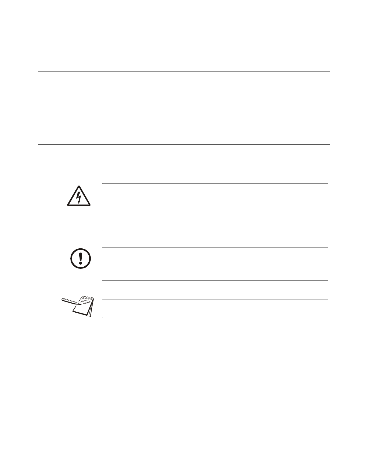
1.2 Special Messages
Examples of special messages you will see in this manual are defined below. The
signal words have specific meanings to alert you to additional information or the relative
level of hazard.
ELECTRICAL WARNING!
THIS IS AN ELECTRICAL WARNING SYMBOL.
ELECTRICAL WARNINGS MEAN THAT FAILURE TO FOLLOW SPECIFIC PRACTICES OR PROCEDURES MAY RESULT IN ELECTROCUTION, ARC BURNS, EXPLOSIONS OR OTHER HAZARDS THAT MAY
CAUSE INJURY OR DEATH.
CAUTION!
This is a Caution symbol.
Cautions give information about procedures that, if not observed, could result
in damage to equipment or corruption to and loss of data.
NOTE: This is a Note symbol. Notes give additional and important information, hints
and tips that help you to use your product.
ZG110 Impact Printer User Instructions 5
Page 6
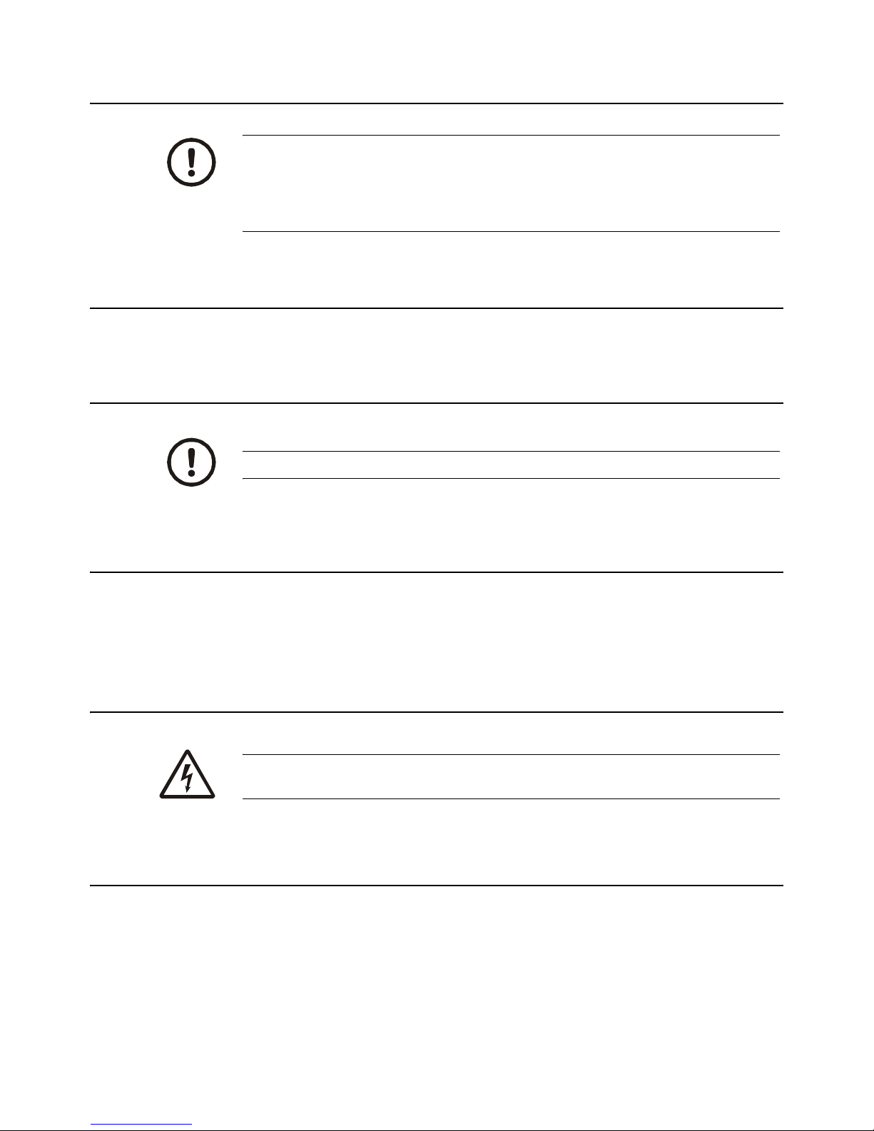
1.3 Electrical Installation
CAUTION: The power cable must be connected to an earth-grounded electrical
outlet. The electrical supply must have a circuit breaker with an appropriate
rating to protect from over-current conditions.
IF IN DOUBT SEEK ADVICE FROM A QUALIFIED ELECTRICIAN.
1.4 Pluggable Equipment
Pluggable equipment must be installed near an easily accessible socket outlet.
1.5 Wet Conditions
The Model ZG110 printer is not a washdown unit. Do not install near water!
1.6 Routine Maintenance
Always turn off the ZG110 and isolate from the power supply before starting any routine
maintenance to avoid the possibility of electric shock.
Make sure that it is placed securely on a flat and level surface.
1.7 Installation
DANGER: RISK OF ELECTRICAL SHOCK. NO USER SERVICEABLE
PARTS. REFER TO QUALIFIED SERVICE PERSONNEL FOR SERVICE.
1.8 Power Supply Details
The ZG110 is directly powered through the power jack at the rear of the printer.
AC Operation
An optional universal power supply may be purchased, part number AWT05-505594.
6 ZG110 Impact Printer User Instructions
Page 7

DC Operation
The printer is designed for direct connection to a +12V or +24V vehicle battery.
Alternatively, the user may make their own power supply arrangements as described
below.
1.8.1 Alternative Power Supply Arrangements
The ZG110 is designed to be operated from a 9V to 36V voltage source that is capable
of supplying the primary power for the printer.
The electrical specification for the power supply input of the ZG110 printer is:
Input Voltage Range: +9V to +36V internal over voltage at 37V and reversal protection
The recommended power supply input is either a 12V or 24V vehicle battery, this allows
the printer to perform at its best. However, the printer will automatically accommodate
any DC input voltage in the range 9V to 36V.
1.9 Printer Firmware Revisions
The manufacturer reserves the right to modify and improve the firmware in its printer
products at any time. Every effort is made to ensure backward compatibility, however,
no guarantee in this respect is given or implied.
1.10 Copyright Notice and Disclaimer
Copyright subsists in the manufacturer's intellectual property, including controller
firmware (embedded software) and circuit diagrams, pin connection lists and
application data. No warranty in respect of patent rights of the manufacturer or of third
parties is given. Unauthorized reproduction or amendment of controller firmware may
result in prosecution.
EPSON is a registered mark of its owner Seiko Epson Corporation. References to this
or other owners' marks in this document are for illustrative purposes only.
The manufacturer does not assume responsibility for interchangeable functionality of
other parties' command sets.
1.11 EMC Caution
System EMC compliance remains the responsibility of the system designer. It is
recommended that screened cables are used; earthing arrangements will depend on
the application.
ZG110 Impact Printer User Instructions 7
Page 8

2 Getting Started
2.1 Connections and EMC Precautions
2.1.1 Printer View (backside)
Power Supply Connector
(PSU Jack Socket)
2.1.2 Connector Details
A single socket on the rear of the printer combines all data and charger functions.
Printer side: Hosiden TCS7167 6-way Socket (mini-DIN style)
User side: Hosiden TCP7160 6-way Plug & Cable or equivalent
RS-232 Connector
(Mini-DIN)
Figure 2.1 Connector view from rear of printer
8 ZG110 Impact Printer User Instructions
Page 9

2.1.3 PSU Jack Socket Detail
Pin Function
1 TxD Data Output
2 BUSY Output
3 RxD Data Input
4 Optional Baud Select
5 Ground (0V)
6 No Connection
Pin Dimension (mm) Function
Inner Inside Ø 2.1 Positive 9-36 VDC Input
Outer Outside Ø 5.5 Negative / 0V Common
The maximum insertion length is 12 mm.
RS232 Data Cable Configuration (9 pin)
A D-9 Female socket with the following pinout:
D-9 Pin Name Function (refers to PC) ZG110 Pin
Shell FGND Frame Ground Screen
6 & 8 CTS & DSR Busy Input 2
2.2 Connecting to a PC
1. Make hardware connections.
1a. Be sure the PC has a D-type serial connector; otherwise, a serial to USB
converter will need to be used.
2. Use one of the two serial ports for the ZG110, whichever is free.
3 TxD Serial Data Output 3
2 RxD Serial Data Input 1
5 SGND Signal Common 0V 5
3. Check that the printer wakes up when the paper feed button is pressed, and
that it produces a Self Test print.
4. Set up the computer's serial port to match the printer
ZG110 Impact Printer User Instructions 9
Page 10

4a. Your proposed application program may have a way of doing this, or you can
get to the DOS prompt [eg C:\>] and type the following command line
(assuming you have connected the printer to COM1:):
MODE COM1:9600,N,8,1 [ENTER]
4b. This will set up the port (COM1:) to 9600 baud, No parity, 8 data bits, and 1
stop bits which is the default setting for the ZG110.
5. Send some data to the printer from your computer
5a. An easy way to do this from the DOS prompt is to type:
DIR >COM1: [ENTER]
This should send a directory listing to the printer. The lines will probably overflow, but
it will at least show that the communication between the computer and the printer is
working.
You can also send data from QBASIC, for example:
OPEN "COM1:9600,N,8,1" FOR RANDOM AS #1
PRINT#1, "Hello"
Alternatively, in Windows, use the terminal (Hyper terminal) program to send some text
to the printer.
2.2.1 Application Program
Once communications between your computer and the printer have been established,
you can try driving the printer from your application program.
10 ZG110 Impact Printer User Instructions
Page 11

3 Modes of Operation
The ZG110 has two operating modes:
l Idle Mode - Awake and ready to accept data, but no data is in the buffer
awaiting printing, and the printer motor is not running
l Printing Mode - Data received into the buffer is printed out
Operational status is indicated by color combinations on the front-panel LED. These
can indicate charger/battery status, paper status and so on.
3.1 Idle Mode
In idle mode, the printer is ready to receive data, which will be printed as soon as
complete lines or graphics patterns are decoded. It responds to the paper feed button
by fast feeding paper.
3.2 Paper Feed Button
As the ZG110 does not have an external power switch so additional functions have
been assigned to the paper feed button.
l In Idle Mode, the Paper Feed Button advances paper at the Fast Feed rate
l In Printing Mode, the Paper Feed Button is ignored
3.3 LED Indications
The LED indicator at the front of the ZG110 provides status information by a number of
color combinations.
3.3.1 Alternative LED Pattern Set
The ZG110 is supplied with an alternative LED pattern set optimized for use with a
direct power pack. This can be summarized as follows:
Steady Green Running OK
Steady Orange Running Low
Pattern Power Pack Paper
No light Not Running N/A
ZG110 Impact Printer User Instructions 11
Page 12

3.4 Printing Method
The ZG110 has the following characteristics:
Printer Type Mech
ZG110 M-190 24 144 0.33 mm 0.37 mm 2.5 Line/s 6.0 mm/s
Characters are 5 dots wide with a 1 dot space between adjacent characters, and most
are 7 dots high. A few (e.g. 'p' or 'q') contain descenders and are 8 dots high. To
optimize throughput the 8th dot line is skipped if no descenders are present in a text
line. Every text line is followed by a 3 dotline space. Text lines may be printed in double
width, double height, or inverted.
During printing the paper is automatically fed by one dot line (0.37mm) each head
cycle. The mechanism can also advance the paper by three dot lines (1.11 mm) in a
single head cycle. This fast feeding is used between text lines, for the Fast Feed
command, and when the paper feed button is pressed.
It is not possible to print partial lines in isolation: if such a line remains in the buffer, it
will not be printed until flushed out by a line terminator or some following data. Any
following data will be printed on the next line. The paper may only be fed through the
printer in the forward direction.
The character set is the standard International IBM® character set, except that it
includes the Euro symbol ('€') at position 80H (128 Decimal), in place of the usual
capital C with cedilla ('Ç').
Characters
per Line
Dots Per
Line
Dot Width
Dot
Height
Print
Speed
Fast Feed
Speed
3.5 Dot Addressable Graphics
Graphics patterns are built up as a succession of complete dot lines across the paper,
rather like a TV picture. Complete dot lines must be specified at a time. The data for
each dot line of graphics should be encoded as shown:
ESC, 02H, d1…d24 (a total of 26 bytes per dot line)
Bits 5 through 0 of each data byte (d
individual dots on the paper, where 1 represents a dot, and 0 represents a space. Bits
7 and 6 are ignored.
Large areas of solid dots are not recommended, as they may cause overheating and
shorten the ribbon life: try shading.
If multiple dot lines of graphics are required to be contiguous, care must be taken to
ensure that the data rate is high enough to allow continuous printing. This is because
the mechanism inserts an additional dot line of space each time the motor stops and
restarts. In order for this effect to be avoided the data for each dot line of graphics must
be ready and waiting in the printer's buffer by the time the previous dot line has been
completed.
through d24 or d40) are interpreted as encoding
1
12 ZG110 Impact Printer User Instructions
Page 13

3.6 Data Buffer
The ZG110 has a nominal 8k byte buffer which enables data to be received while
previous lines are being printed. The state of the data buffer is reported to the host by
both hardware and software handshaking.
The hardware busy line is asserted when 512 bytes of space remains; and incoming
data are no longer passed to the buffer when 48 bytes remain. The hardware busy line
goes ready again when 528 bytes become free.
The ZG110 transmits software handshaking codes when the buffer status changes, as
follows:
XON 11H Start transmission
Meaning: The buffer is ready to receive data.
Transmitted after a reset, or when the data buffer empties to only 1/4 full.
XOFF 13H Stop transmission
Meaning: The buffer is not ready to receive data.
Transmitted when the data buffer becomes 3/4 full.
3.7 Serial Interface (standard RS-232 version)
Two versions are available which offer a default serial interface format is 9,600 baud,
8 data bits, 1 or 2 stop bits, and no parity or 1200 baud, 8 data bits, 1 or 2 stop bits, and
no parity.
Serial data is expected on RxD in RS-232C format with -12V meaning 'mark' or logical
'1', and +12V meaning 'space' or logical '0', with reference to the common ground. The
serial data output line, TxD, transmits XON/XOFF to the host at the same baud rate and
format as the serial data input. The hardware busy line, Busy, is true (nominally -12V)
when busy.
Some host equipment use a constant space condition (+12V) to indicate a reset
condition or wait state. Some battery powered host equipment present the same output
signal when they go to sleep. By default the ZG110 will ignore this condition, but this
type of host behavior may result in one or more spurious characters being received by
the ZG110.
ZG110 Impact Printer User Instructions 13
Page 14

4 Control Code Tables
Codes from 20H to FFH are printable characters. Codes from 00H to 1FH which are
not listed below are ignored. Codes forming part of an ESC sequence are exceptions
to these rules and may be any value.
All control codes, except the 'CAN' code, are executed when they fall through the data
buffer at printing time.
4.1 Codes Received by the ZG110
LF 0AH Line Feed (Line Terminator)
Works in an either/or way with CR: CR/LF pairs are treated as
a single line terminator. Line terminators immediately following
full print lines are ignored.
VTAB 0BH Vertical TAB
Exactly equivalent to the command ESC,2AH.
Fast feed of 30 (10x3) dot line pitches.
CR 0DH Carriage Return (Line Terminator)
Works in an either/or way with LF. CR/LF pairs are treated as a
single line terminator.
CAN 18H (Real time) Abort printing and Reset
Executed immediately when received. Printing may be interrupted part way through a line.
All Print Mode settings are cleared. The ZG110 is actually RESET when the CAN code is
received, so any data sent immediately following the CAN code will be lost. The printer
transmits an XON character when it is ready to receive data again.
14 ZG110 Impact Printer User Instructions
Page 15

ESC,n 1BH,n Self Test, Fast Feed, Graphics and Print Mode Selection
Note: All ESC sequences should appear at the start of a logical line. If one is received within a
normal printable line a line terminator will automatically be inserted before it.
If n is an ESC character (1BH): [ Self Test Print ]
m A self test print is produced. This consists of a line reporting the firmware
version number, and a single dump of the entire character set.
Otherwise, if bit 5 of n is set: [ Fast Feed Command ]
m The least significant 5 bits of n (bits 4 through 0) are used as a binary count for
a fast feed operation, encoding the number of 3 dot pitches the paper to be
fed.
Otherwise, if bit 1 of n is set: [ Dot Addressable Graphics Mode ]
m The following 24 or 40 bytes are interpreted as graphics patterns. .
Otherwise: [ Print Mode Selection ]
n is interpreted as follows:
Bit 0 Select(1) or Clear(0) Inverted Print Mode
Bit 1 Must be zero
Bit 2 Select(1) or Clear(0) Double Width Mode
Bit 3 Select(1) or Clear(0) Double Height Mode
Bit 4 Ignored
Bit 5 Must be zero
Bit 6 Ignored
Bit 7 Ignored
Print Modes may be combined as required, but affect entire print lines. It is not possible, for
example, to mix Double Width and Normal Width text on the same print line.
Each of these Print Modes remains in force until actively cancelled.
ZG110 Impact Printer User Instructions 15
Page 16

5 Paper and Ribbons
The ZG110 is normally supplied with a separate paper roll and fitted with a black ribbon.
Paper rolls must be 57.5 ±0.5mm, and of maximum diameter 60mm.
Alternative paper roll sizes, alternative paper roll types (e.g. two-part paper, 'action'
paper, etc) and commodity packs, containing several standard paper rolls and ribbons,
are all available.
5.1 Loading Paper
A paper roll is normally supplied separately to avoid unrolling or damage in transit.
To load a new roll of paper:
1. Discard a few turns of paper in case of glue or damage.
2. Mount the roll between the bosses in the paper holder area: the right-hand
boss is on a sprung support. The paper should flow from the bottom of the roll.
3. Prepare the end of the paper into a clean edge at right-angles, and introduce
into the rear of the mechanism while pressing the paper feed button: the target
point is just above a bright metal strip. The paper should be straight, and
pointing forwards into the printer.
4. Once the mechanism grips the paper, allow enough to feed through for good
alignment, thread the paper through the exit slot and close the lid.
5. Check that it still advances properly, and tear off any excess by pulling the
paper sharply towards you across the serrated edges.
5.2 Paper Low Sensor
A mechanical/optical paper sensor acts on the left-hand face of the paper roll, and is
activated when only a few metres of paper remain. When this sensor becomes active,
the LED indicates solid flashes orange.
To avoid spurious 'paper low' reports, ensure that the roll is correctly located on the
bosses, and that the right-hand paper support has returned to the vertical position.
5.3 Removing Paper or Clearing a Jam
If some paper remains in the printer when a new roll is required or a paper jam has
occurred, do not to pull the paper out of the printer in a reverse direction.
Do not pull paper in the reverse direction out of the printer. This can cause
permanent damage to the mechanism.
16 ZG110 Impact Printer User Instructions
Page 17

When it is necessary to remove the paper from the mechanism, for example when
replacing the paper before the end of a roll, or to clear a paper jam, proceed as follows:
1. Tear off any paper coming out of the paper exit slot.
2. Open the printer cover, and carefully remove the paper roll, allowing it to
unroll.
3. Cut the paper straight across between the roll and the mechanism.
4. Using the paper feed button, advance the remaining paper until it is completely
out of the mechanism; or, if the mechanism and paper are jammed, carefully
pull the paper by hand in the normal feeding direction, taking care not to tear
the paper or apply excessive force to any part of the mechanism.
5. Press the paper feed button to exercise the printer for a few cycles and ensure
that it is running freely.
6. Load a new roll of paper as described above.
5.4 Changing the Ink Ribbon Cartridge
The ink ribbon cartridge can be removed and refitted either with or without paper in the
mechanism. The exposed part of the ink ribbon must lie between the front side of the
paper (facing the operator) and the mechanism.
To change the ink ribbon cartridge:
1. Open the printer cover, and snap out the old cartridge by pressing down on the
right-hand end (marked "PUSH"). Carefully lift the cartridge so that the ribbon
comes away from between the paper (if fitted) and the mechanism.
2. Check that the exposed part of the ribbon spans the new cartridge tightly; if
not, wind it up using the small knurled knob.
3. Fit the new cartridge, ensuring that the ink ribbon lies neatly between the
mechanism and the paper. If the paper is already in place, it will be necessary
to thread the paper through the loop of the ribbon.
4. Press the paper feed button to advance some paper and check that the paper
and ribbon are moving freely. Allow enough to feed the paper through the exit
slot, and close the lid. Tear off any excess by pulling the paper sharply towards
you across the serrated edges.
5. If possible, perform a test print to ensure that all is well.
ZG110 Impact Printer User Instructions 17
Page 18

Page 19

Avery Weigh-Tronix USA
1000 Armstrong Dr.
Fairmont MN 56031 USA
Tel:507-238-4461
Fax:507-238-4195
Email: usinfo@awtxglobal.com
www.wtxweb.com
Avery Weigh-Tronix UK
Foundry Lane,
Smethwick, West Midlands,
England B66 2LP
Tel:+44 (0) 8453 66 77 88
Fax: +44 (0)121 224 8183
Email: info@awtxglobal.com
www.averyweigh-tronix.com
 Loading...