

Page 1

XLR Agricultural Remote Display
XLR-6, XLR-8 AND XLR-12 Models
Installation and Technical Instructions
AWT35-500576
Issue AF
Page 2

Avery Weigh-Tronix is a trademark of the Illinois Tool Works group of companies whose ultimate parent company is
Illinois Tool Works Inc (“Illinois Tool Works”). Copyright © 2015 Illinois Tool Works. All rights reserved.
No part of this publication may be reproduced by making a facsimile copy, by the making of a copy in three dimensions of a two-dimensional
work and the making of a copy in two dimensions of a three-dimensional work, stored in any medium by electronic means, or transmitted in
any form or by any means, including electronic, mechanical, broadcasting, recording or otherwise without the prior written consent of the
copyright owner, under license, or as permitted by law.
This publication was correct at the time of going to print, however Avery Weigh-Tronix reserves the right to alter without notice the
specification, design, price or conditions of supply of any product or service at any time.
XLR6_8_12_i_en_500576.book
Page 3

Table of Contents
Chapter 1 General Information and Warnings ........................................................................................ 5
About this Manual ..............................................................................................................5
Text Conventions ........................................................................................................5
Special Messages .......................................................................................................5
Installation ....................................... .................................... ...................................... .........6
Routine Maintenance .........................................................................................................6
Cleaning the Machine ........................................................................................................6
Training ..................................... ................................................................ .........................6
Sharp Objects .............................................................................. .... ... ... ............................6
Declaration of Conformity (CE approval) ........................................................................... 7
FCC and EMC Declarations of Compliance .......................................................................8
Technical Support ..............................................................................................................8
Chapter 2 Introduction .............................................................................................................................. 9
Chapter 3 Installation .............................................................................................................................. 10
Mounting Brackets ...........................................................................................................10
Adapter Mounting Plate ..................... .... ... ... ... .... .............................................................11
Stainless Steel Shield ......................................................................................................11
Connecting the Display to Your Equipment .....................................................................12
XLR-8 / XLR-12 Connections ....................................................................................12
XLR-6 Connections ...................................................................................................13
Cables ....................................................................................................................... 14
Stainless Steel Shield Installation ....................................................................................15
Setup of AWT Ag Indicators for Use With XLR Displays .................................................16
Setup for 640 Series Indicators .................................................................................16
Setup for 1040 and 2040 Series Indicators ...............................................................17
Setup for 2060 Indicators ..........................................................................................17
Setup for 3060 Touch Screen Indicators ...................................................................18
Using two XLR's with 2060 or 3060 Indicators ..........................................................18
Setup for Digi-Star Indicators ....................................................................................19
Chapter 4 Communicating With the Remote Display .............................................................. ............. 20
Computer Control Protocol ..............................................................................................20
Transmit a Weight String ...........................................................................................21
Transmit Status Characters .......................................................................................21
Transmit an Alphanumeric Message / Data String ....................................................21
Control Commands ...................................................................................................22
Sample Data Strings Sent to the Display ..................................................................22
Connector Pin outs ................................................... ... .... ... ... ... ... ....................................23
Chapter 5 Learn a New Transmitter Code (channel 1) ......................................................................... 24
Chapter 6 Specifications and Parts Lists .............................................................................................. 25
Specifications .................................. .................................... ...................................... .......25
Service Parts List ...... ...................................... .... ... ....................................... ... ... ... ..........26
Accessory Parts List ........................................................................................................27
XLR-6, XLR-8 and XLR-12 Installation Instructions 3
Page 4

4 XLR-6, XLR-8 and XLR-12 Installation Instructions
Page 5
1 General Information and Warnings
1.1 About this Manual
This manual is divided into chapters by the chapter number and the large text at the top
of a page. Subsections are labeled as shown by the 1 and 1.1 headings shown above.
The names of the chapter and the next subsection level appe ar at the top of alternating
pages of the manual to remind you of where you are in the manual. The manu al name
and page numbers appear at the bottom of the pages.
1.1.1 Text Conventions
Key names are shown in bold and reflect the case of the key being described. This
applies to hard keys and onscreen or soft keys.
Displayed messages appear in bold italic type and reflect the case of the displayed
message.
1.1.2 Special Messages
Examples of special messages you will see in this manual are defined below. The
signal words have specific meanings to alert you to additional inform ation or the relative
level of hazard.
ELECTRICAL WARNING!
THIS IS AN ELECTRICAL WARNING SYMBOL.
ELECTRICAL WARNINGS MEAN THAT FAILURE TO FOLLOW
SPECIFIC PRACTICES OR PROCEDURES MAY RESULT IN
ELECTROCUTION, ARC BURNS, EXPLOSIONS OR OTHER HAZARDS
THAT MAY CAUSE INJURY OR DEATH.
WARNING!
This is a Warning symbol.
Warnings mean that failure to follow specific practices and procedures may
have major consequences such as injury or death.
CAUTION!
This is a Caution symbol.
Cautions give information about procedures that, if not observed, could result
in damage to equipment or corruption to and loss of data.
NOTE: This is a Note symbol. Notes give additional and important information, hints
and tips that help you to use your product.
XLR-6, XLR-8 and XLR-12 Installation Instructions 5
Page 6

1.2 Installation
DANGER: RISK OF ELECTRICAL SHOCK. NO USER SERVICEABLE
PARTS. REFER TO QUALIFIED SERVICE PERSONNEL FOR SERVICE.
1.3 Routine Maintenance
Always turn off the machine and isolate from the power supply before starting any
routine maintenance to avoid the possibility of electric shock.
Make sure that it is placed securely on a flat and level surface.
1.4 Cleaning the Machine
Table 1.1 Cleaning DOs and DON’Ts
DO DO NOT
Wipe down the outside of standard products
with a clean cloth, moistened with water and
a small amount of mild detergent
Spray the cloth when using a proprietary
cleaning fluid
1.5 Training
Do not attempt to operate or complete any procedure on a machine unless you have
received the appropriate training or read the instruction books.
1.6 Sharp Objects
Do not use sharp objects such as screwdrivers or long fingernails to operate the keys.
Attempt to clean the inside of the machine
Use harsh abrasives, solvents, scouring cleaners or
alkaline cleaning solutions
Spray any liquid directly on to the display windows
6 XLR-6, XLR-8 and XLR-12 Installation Instructions
Page 7
1.7 Declaration of Conformity (CE approval)
The following XLR-6, XLR-8, and XLR-12 part numbers are CE approved:
Model Part Number
XLR-6 AWT05-508584
XLR-8 AWT05-507376
XLR-12 AWT05-507377
XLR-6, XLR-8 and XLR-12 Installation Instructions 7
Page 8

1.8 FCC and EMC Declarations of Compliance
United States
This equipment has been tested and found to comply with the limits for a Class A digital device, pursuant to Part 15 of the FCC Rules.
These limits are designed to provide reasonable protection against harmful interference when the equipment is operated in a
commercial environment. This equipment generates, uses, and can radiate radio frequency energy and, if not installed and used in
accordance with the instruction manual, may cause harmful interference to radio communications. Operation of this equipment in a
residential area is likely to cause harmful interference in which case the user will be required to correct the interference at his own
expense.
Canada
This digital apparatus does not exceed the Class A limits for radio noise emissions from digital apparatus set out in the Radio
Interference Regulations of the Canadian Department of Communications.
Le présent appareil numérique n’émet pas de bruits radioélectriques dépassant les limites applicables aux appareils numériques de
la Classe A prescrites dans le Règlement sur le brouillage radioélectrique edicté par le ministère des Communications du Canada.
European Countries
WARNING: This is a Class A product. In a domestic environment, this product may cause radio interference in which the user may be
required to take adequate measures.
1.9 Technical Support
24/7 Customer Support
Avery Weigh-Tronix is dedicated to customer service. W e under sta nd downtim e is not
an option for AG producers and we're ready to help anytime. The technical suppo rt
team for all Avery Weigh-Tronix agri-business scales is available 24 hours a day 7 days
a week.
Ag Technical Support GroupUSA and Canada:
Toll free Phone: (800) 458 - 7062
Outside USA: (507) 238-8261
Tech Support Phone 7:00 am to 5:00 pm CST (800) 458-7062 Ext. 8261
Tech Support Phone/ after hours answering 5:00 pm to 7:00 am CST (800) 458-7062
Service e-mail:
usservice@awtxglobal.com
8 XLR-6, XLR-8 and XLR-12 Installation Instructions
Page 9
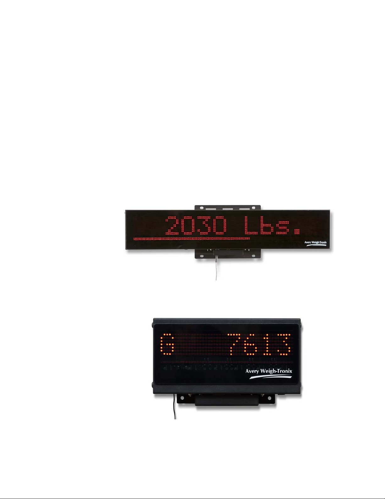
2 Introduction
The XLR-6, XLR-8 and XLR-12 remote displays incorporate the most features and
highest performance standards of any agricultural weighing display; making them the
best choice for remote viewing applications.
The XLR series features:
l Scrolling 8 or 12 character full Alphanumeric Display.
l Ultra wide viewing angles up to 120 degrees.
l Multi interface support including: Avery Weigh-Tronix, Digi-Star and RS-232
Computer interfaces.
l Quad (single for XLR-6) LED digits offering bold and easy to read digits in
direct sunlight.
l Dedicated bar graph assists in loading of ingredients.
l Large G and N annunciator for clear Gross/Net indication.
l Built-in standard Radio Clicker for ingredient advancement.
l Auto brightness control dims the display for ease of readin g dis pla y at night
time (XLR-8 and XLR-12 only).
l Easy to use communication protocol for custom applications.
l Same installation bracket and bolt pattern across all 3 models.
Figure 2.1 XLR-8 and XLR-12 Remote Display
Figure 2.2 XLR-6 Remote Display
NOTE: Remove the protective film on the XLR display. If the film is left on, it will
bake on the display over a period of time and decrease visibility.
XLR-6, XLR-8 and XLR-12 Installation Instructions 9
Page 10

3 Installation
3.1 Mounting Brackets
The XLR-6, XLR-8 and XLR-12 all have the same mounting bracket options and bolt
pattern.
The display is to be mounted on a solid mounting bracket or surface. The antenna wire
at the bottom right side of the unit should never be cut or pinched during installation.
The XLR remote display is equipped to support equipment that already has a
preexisting rail mount type bracket which is commonly used ( refer to section 3.2). The
display can alternatively be mounted using 4 mounting holes shown below. Use
minimum 3/8-16 UNC, 3/4" bolts or equivalent to mount.
Figure 3.1 Standard Mounting Bracket
Figure 3.2 Rail Mount Bracket
10 XLR-6, XLR-8 and XLR-12 Installation Instructions
Page 11

3.2 Adapter Mounting Plate
When utilizing the Rail Mount bracket (refer to Figure 3.2), there is an adapter mounting
plate (PN AWT20-504460), see Figure 3.3.
Weld or mount the plate to a surface. You can use hose clamps through the slots
marked with a A in Figure 3.3 to mount it to a pole or post.
There must be a 1/2 space between the plate and the mountin g surface to allow room
for the XLR to fit over the mounting plate.
Slip the mounting plate up into the slot on the back of the XLR and use bolts to attach
the XLR to the mounting plate through the bottom, mating holes marked with the letter
B in Figure 3.3.
The other holes are used to mount various other Avery We igh-tronix V -mount bracket s
and objects.
Figure 3.3 Adaptor Mounting Plate
3.3 Stainless Steel Shield
It is highly recommended to use the optional S t ainless S teel Shield with the XLR series
remote display. The Stainless Steel shield will help keep dust and moisture off of the
display to improve viewing quality.
Part Number Description
AWT20-508532 Protective Stainless Steel Shield XLR-6
AWT20-504832 Protective Stainless Steel Shield XLR-8
AWT20-504833 Protective Stainless Steel Shield for XLR-12
XLR-6, XLR-8 and XLR-12 Installation Instructions 11
Page 12

3.4 Connecting the Display to Your Equipment
All connections are made at the bottom of the unit using Amphenol 8-pin RS-232
circular connectors. All power and communications goes through a single cable.
NOTE: The XLR remote never needs to be opened for wiring. There are no switch
settings or internal adjustments required.
CAUTION: Never pressure wash your display as water may be forced through
the connectors causing electrical problems.
3.4.1 XLR-8 / XLR-12 Connections
If you are connecting to Avery Weigh-Tronix or equipment that uses RS-232
communications, then you will be connecting to connector A (8 pin male). If you are
using Digi-Star equipment then connect to connector B (8 pin female). Use only
supplied cable assemblies from the manufacturer.
Figure 3.4 XLR-8 / XLR-12 Connector Configuration
12 XLR-6, XLR-8 and XLR-12 Installation Instructions
Page 13

3.4.2 XLR-6 Connections
If you are connecting to Avery Weigh-Tronix or equipment that uses RS-232
communications, then you will be connecting to connector B (8 pin male). If you are
using Digi-Star equipment then connect to connector A (8 pin female). Use only
supplied cable assemblies from the manufacturer.
Figure 3.5 XLR-6 Connector Configuration
XLR-6, XLR-8 and XLR-12 Installation Instructions 13
Page 14

3.4.3 Cables
Part Number Description
Remote Display Cable with Power Supply
Part Number Description
AWT25-500473 10 ft / 3.1 m Cable Assembly, Serial RD with power
AWT25-500477 30 ft / 9.2 m Cable Assembly, Serial RD with power
Extension Cable
AWT25-501728 10 ft / 3.1 m extension cable to use with Serial RD cable assembly. This creates a
disconnect point between the indicator in the cab's cable and the remote display's
cable. Very useful when connecting and disconnecting mixer wagon to tractor.
Digi-Star Remote Display Cables
Part Number Description
AWT25-500928 15 ft / 4.6 m Cable Assembly, Interface to Digi-Star
AWT25-500929 30 ft / 9.2 m Cable Assembly, Interface to Digi-Star
14 XLR-6, XLR-8 and XLR-12 Installation Instructions
Page 15

3.5 Stainless Steel Shield Installation
without shield
with shield
without shield
1. Loosen the screws (two on each side) on both ends of the XLR remote display.
Refer to Figure 3.6 for screw location.
2. Slide the shield in place so that the 4 slots in the shield ends slide over the
screws.
3. Tighten the screws to secure the shield.
Figure 3.6 XLR-6 Protective Shield Installation
Figure 3.7 XLR-8 Protective Shield Installation
XLR-6, XLR-8 and XLR-12 Installation Instructions 15
Page 16

Figure 3.8 XLR-12 Protective Shield Installation
without shield
with shield
3.6 Setup of AWT Ag Indicators for Use With XLR Displays
Following are the instructions you need to setup an Avery Weigh-Tronix AG indicator
(Models: 640 Series; 640M, 640, 640XL, 1040/2040, 2060 and 3060) for use with an
XLR remote display
3.6.1 Setup for 640 Series Indicators
When using an XLR series remote display with an 640 Series indicator, an RS-232
serial port is required for the communication. Please verify that the 640 Series has one
free serial port before continuing through the setup steps. See the illustration of the port
connection in Figure 3.9.
Figure 3.9 RS-232 port Connection
To configure to communicate with th e XLR remote display, use the settings spelled out
in the list below. You may need to reference the 640 Series Service manual or contact
your Avery Weigh-Tronix provider for support. Multiple ports are available on the 640
Series, either Port1 or Port2 supports the XLR.
16 XLR-6, XLR-8 and XLR-12 Installation Instructions
Page 17

640 RS-232 Port Settings for XLR Series Remotes
l Baud = 9600
l Parity = None
l Data = 8
l Hand = None
l Layout = Remote
When these settings are used, the XLR remotes will show the same information that is
shown on the display of the 640 Series indicator. The XM60 transmitter is standard in
the XLR remote. When used, it will perform a programmable function for Input 2 in the
640 Series. Changing this function is done in the 640 Series menus and can be
changed by referencing the 640 Series service manual.
3.6.2 Setup for 1040 and 2040 Series Indicators
When using the XLR Series remotes with the 1040 or 2040 indicators, a serial port is
also required. This is the same connection as used in the 640 Series. Please r eference
the port connection shown in Figure 3.9 for reference whe n verifying the 1040/2040 has
the required ports.
1040 and 2040 RS-232 Port Settings for XLR Series Remotes
l Baud = 9600
l Parity = None
l Data = 8
l Hand = None
l Layout = RD40RF
All of the messages and weights that are show on the display of the indicator will be
shown on the XLR remote. The XM60 Transmitter is standard in the XLR remote
displays. When used with the 1040, it will advance to the next ingredient in the recipe.
3.6.3 Setup for 2060 Indicators
All 2060 indicators come standard with two Serial port s. Com port 1 is set as the default
remote display port. Com port 1 is always the serial port closest to the Weigh Bar
connectors.
2060 RS-232 Port Settings for XLR Series Remotes
l Baud = 9600
l Data (D-Bits) = 8
l Parity = None
l S-Bits = 1
l Hand (C-trol) = None
XLR-6, XLR-8 and XLR-12 Installation Instructions 17
Page 18

3.6.4 Setup for 3060 Touch Screen Indicators
From Indicator
From Power Supply
To XLR with Active Transmitter
To XLR with Inactive Transmitter
RS-232 Com port 2 or Com port 3 can run the XLR. If Feed Foreman is loaded on th e
3060, Com port 3 must be used.
3060 touch screen RS-232 Port Settings for XLR Series Remotes
l Baud = 9600
l Parity = None
l Data = 8
l Stop Bits = 1
l Hand = None
l Power = On
3.6.5 Using two XLR's with 2060 or 3060 Indicators
In order to run two XLR remotes with the 2060 or 3060, PN AWT05-505541 (XLR
Series Junction box) will be needed. Decide which XLR will have the active XM60
transmitter. In this setup one XLR will simply display weight and a second will also be
synced to a transmitter. Refer to Figure 3.10 for connection details.
18 XLR-6, XLR-8 and XLR-12 Installation Instructions
Figure 3.10 RS-232 Junction Box Connections
Page 19

3.6.6 Setup for Digi-Star Indicators
When using the XLR Series remotes with Digi-Star indicators:
1. Connect the XLR to the J-903 Remote port on the EZ-III indicator models (XLR
series is not compatible with EZ-II indicator models.)
Use the AWT Digi-Star interface cable from Avery Weigh-Tronix (PN
AWT25-500928 or AWT25-500929) or the standard cable supplied by
Digi-Star.
2. Follow instructions below based on the Digi-Star model of indicator you are
interfacing to.
Avery Weigh-Tronix XLR series cables for inte rfacing to Dig i-Star
indicators
l AWT25-500928 15 ft / 4.6 m Cable Assembly, Interface to Digi-Star
l AWT25-500929 30 ft / 9.2 m Cable Assembly, Interface to Digi-Star
EZ3 Indicators with full alpha and alph anumeric keypad (GT460, NT460,
EZ4600, EZ3600V, EZ3400VL, and EZ3400)
1. Enter 234 and press Select.
2. Press Select until EZ3MUX is displayed.
3. Press Enter.
EZ3 Indicators with alphanumeric keypad (EZ2500V, EZ2400V, EZ400,
and GT400)
1. Press Net/Gross first and then press On and hold them both down at the same
time until scrolling message "Press Select or Net…." appears.
2. Press Select until Menu2 appears and press On.
3. Press On until RMDisp appears then the current selection appears (EZ3MUX
or EZ2).
4. Press Select until EZ3MUX appears then press On.
5. Cycle power by turning the indicator off then back on or press On until you get
into weighing mode.
XLR-6, XLR-8 and XLR-12 Installation Instructions 19
Page 20

4 Communicating With the Remote Display
The XLR display automatically selects which type of communications protocol is being
used. When connecting to Avery Weigh-T ronix or Digi-Star equipment, the display will
automatically translate the display information correctly. No configuring of the display
is required. There are no adjustable settings for this display.
When transmitting weights to the display the annunciator character located on the left
hand side of the display will clearly display a G for gross weight or N for net weight. For
Digi-Star equipment the annunciator character will also flash L when loading
ingredients.
When the display is displaying alpha numeric text messages, the annunciator character
is not displayed.
The bar graph located across the bottom indicat es how clo se yo u ar e to target when
loading product. This is displayed as % of target weight.
4.1 Computer Control Protocol
If the display information is sent from alternate equipment using RS-232, then the
equipment’s baud rate must be set to 9600 no parity and 1 stop bit (9600 N81).The
display will attempt to analyze and display the weight information automatically.
NOTE: When connecting to non-A very Weig h-Tronix equipment, 12V must be applied
to the remote power pin 7 on the connector.
Custom applications may communicate to the display using a simple command
protocol that allows applications to make full use of all of the displays features.
All commands sent to the display must terminate with a CR character ASCII 13.
20 XLR-6, XLR-8 and XLR-12 Installation Instructions
Page 21

4.1.1 Transmit a Weight String
Use numeric ASCII characters followed by a <CR> character. Weights are displayed
from right to left.
Example:
l To display “1000”, transmit: 1000<CR>
4.1.2 Transmit Status Characters
Status characters may be embedded anywhere in the weight string to control the
annunciator characters ‘G’ or ‘N’. Status characters may be upper or lowercase, and in
any order, before or after the weight.
STATUS COMMAND ASCII DEC
GROSS weight G or g 71 or 103
NET weight N or n 78 or 110
Example:
l To display 1000 lb gross, transmit: 1000G<CR> -or- g1000<CR>
If no gross/net character is sent to the XLR, the “G” annunciator will be displayed by
default.
4.1.3 Transmit an Alphanumeric Message / Data String
The XLR can display the entire printable ASCII character set and supports scrolling
messages. When an alphanumeric data string is longer than the unit’s number of
display characters, the message will scroll (right to left).The maximum data string
length is 40 characters.
Alphanumeric message data strings must be preceded by the “ character (decimal 34)
and followed by a Carriage Return <CR> character (decimal 13) to differentiate them
from weight strings. Characters are displayed from left to right.
Example:
l To display the message Mixing transmit: “Mixing<CR>
XLR-6, XLR-8 and XLR-12 Installation Instructions 21
Page 22

4.1.4 Control Commands
Control commands are ASCII characters (preceded by @ and followed by <CR>) that
are transmitted to the display to control modes of operation. Numeric parameters
(when needed) follow the command character before <CR>.
CONTROL COMMAND ASCII DEC
Turn ON flashing display ( 40
Turn OFF flashing display ) 41
FLASH display 3 times ! 33
Scroll speed (1-3) 1=fast, 2=medium, 3=slow (default is 2) = 61
Bar Graph (0 – 100) ^ 94
Control Commands must be transmitted alone. Do not transmit Control Commands
within a WEIGHT data string or an alphanumeric message data string.
4.1.5 Sample Data Strings Sent to the Display
DATA STRING DISPLAY
0<CR> “G 0”
1000 <CR> “G 1000”
N 1234 <CR> “N 1234”
1234 g <CR> “G 1234”
“COTTON<CR> “ COTTON”
“Pen 12<CR> “ Pen 12”
“HOLD!<CR>@!<CR> “ HOLD!” flashing 3 times
“Avery Weigh-Tronix<CR> “Avery Weigh-Tronix” scrolling
@=3<CR>“Next Pen Number<CR> “Next Pen Number” slow scroll
@^50<CR> Bar graph = 50%
22 XLR-6, XLR-8 and XLR-12 Installation Instructions
Page 23

4.2 Connector Pin outs
When using Connector A, 12V must be supplied to Pin 7 for the unit to turn on.
Avery Weigh-Tronix RS-232 (8 pin male)
Pin 1 Not used
Pin 2 RS232 Tx
Pin 3 Not used
Pin 4 RS232 Rx
Pin 5 GND
Pin 6 GND
Pin 7 PWR ON
Pin 8 +12V
Digi-Star (8 pin female)
Pin 1 +12V
Pin 2 +12V
Pin 3 Clicker
Pin 4 Data
Pin 5 Clock
Pin 6 GND
Pin 7 Not used
Pin 8 GND
XLR-6, XLR-8 and XLR-12 Installation Instructions 23
Page 24

5 Learn a New Transmitter Code (channel 1)
1. Press the mode switch, pointed out in Figure 5.1.
The green LED will start to flash quickly.
Figure 5.1 Mode button on the remote receiver (PN AWT25-500927)
2. While the green LED is flashing quickly (approximately 15 seconds), press the
button on the remote transmitter shown in Figure 5.2.
The green LED will flash once and then turn off to show that the button
was learned.
Figure 5.2 Remote button (AWT15-501088)
3. Repeat steps 1 and 2 to learn more buttons into ch annel 1.
24 XLR-6, XLR-8 and XLR-12 Installation Instructions
Page 25

6 Specifications and Parts Lists
6.1 Specifications
Power
Supply Voltage: 11V to 24V DC
XLR-6 Max 3A (all LEDs on)
Typically >1A at 12V
XLR-8 Max 3.5A (all LEDs on)
Typically >1.5A at 12V
XLR-12 Max 4.5A (all LEDs on)
Typically >2.5A at 12V
Input Protection: Reverse Polarity with Thermal Fuse
Display
Display color: RED
Display Viewing Angle: 120 degrees
Number of Characters: 8 (XLR-6), 8 (XLR-8) and 12 (XLR-12)
Longest scrolling message displayable: 40 characters
Bargraph: 48 segments
Dimensions
Width: 13.25” (336.5 mm)
Height: 10.250” (260.4 mm)
Depth: 2.580” (65.5 mm)
Weight:
7lbs (3.2 kg)
Communication
Avery Weigh-Tronix Connector:
Voltage levels: RS-232
Input protocol: Avery Weigh-Tronix and Computer Control
Baud Rate: 9600 N81
Remote power ON signal pin 7: 5V -12V DC
Digi-Star Connector:
Voltage Levels: 5V Synchronous Clocked Data
Input Protocol: Digi-Star Remote display
Remote Clicker output: Transistor Open Collector to GND
Environment
Operating Temperature: -20° F to 140° F (-30° C to 60° C)
Agencies
FCC: CFR47 Part 15
Industry Canada: ICES-003 Issue 5
CE Approved
Warranty:
Three years
XLR-6, XLR-8 and XLR-12 Installation Instructions 25
Page 26

6.2 Service Parts List
AWTX Part # AWTX Description
XLR-6 Remote Display
AWT05-508244 Complete Remote Display, XLR-6 LED
AWT25-501915 Digit Board, 8 digit x 2”, XLR-6
AWT20-508551 Enclosure, Rear XLR-6 LED Remote
AWT20-508552 Enclosure, Front XLR-6 LED Remote
AWT20-508553 Lens Assy, Non-Glare XLR-6 (adh. gasket inc.)
AWT20-508554 Gasket, XLR-6 Remote
AWT20-508550 Cover, connector, XLR-6
AWT20-508532 Protective Stainless Steel Shield XLR-6
XLR-8 Scoreboard Remote Display
AWT05-503508 Complete Remote Display, XLR-8 LED
AWT20-504260 Enclosure, Rear XLR-8 LED Remote
AWT20-504261 Enclosure, Front XLR-8 LED Remote
AWT20-504262 Lens Assy, Non-Glare XLR-8 (adh. gasket inc.)
AWT20-504263 Gasket, XLR-8 Remote
AWT20-508548 Cover, connector, XLR-8
AWT20-504832 Protective Stainless Steel Shield XLR-8
AWT20-504269 Display Card, 4 Digit XLR Series
XLR-12 Scoreboard Remote Display
AWT05-503509 Complete Remote Display, XLR-12 LED
AWT20-504264 Enclosure, Rear XLR-12 LED Remote
AWT20-504265 Enclosure, Front XLR-12 LED Remote
AWT20-504266 Lens Assy, Non-Glare XLR-12 (adh. gasket inc.)
AWT20-504267 Gasket, XLR-12 Remote
AWT20-508549 Cover, connector, XLR-12
AWT20-504833 Protective Stainless Steel Shield for XLR-12
AWT20-504269 Display Card, 4 Digit XLR Series
XLR Common Parts
AWT20-504268 Controller Board, XLR Series
AWT25-501916 Wiring Harness, male conn., XLR
AWT25-501917 Wiring Harness, female conn., XLR
AWT15-501088 Remote Transmitter
AWT25-500927 Remote Receiver
26 XLR-6, XLR-8 and XLR-12 Installation Instructions
Page 27

6.3 Accessory Parts List
Part Number Description
AWT25-500473 10 ft / 3.1 m Cable Assembly, Serial RD with power
AWT25-500477 30 ft / 9.2 m Cable Assembly, Serial RD with power
AWT25-501728 10 ft / 3.1 m extension cable to use with Serial RD cable assembly. This creates
a disconnect point between the indicator in the cab's cable and the remote
display's cable. Very useful when connecting and disconnecting mixer wagon to
tractor.
AWT25-500928 15 ft / 4.6 m Cable Assembly, Interface to Digi-Star
AWT25-500929 30 ft / 9.2 m Cable Assembly, Interface to Digi-Star
AWT20-508532 Protective Stainless Steel Shield XLR-6. Helps keep dust and moisture off
display to improve viewing quality.
AWT20-504832 Protective Stainless Steel Shield XLR-8. Helps keep dust and moisture off
display to improve viewing quality.
AWT20-504833 Protective Stainless Steel Shield for XLR-12. Helps keep dust and moisture off
display to improve viewing quality.
AWT15-50188 Extra XM60 Remote Transmitter
AWT20-504460 XLR Mounting Plate Adapter
AWT05-505541 2 Remote Splitter Box for connecting 3060 with Feed Foreman to 2 XLR remote
displays (2nd separate Amp power source is needed for J-box)
XLR-6, XLR-8 and XLR-12 Installation Instructions 27
Page 28

28 XLR-6, XLR-8 and XLR-12 Installation Instructions
Page 29

Page 30

To access manuals on
Avery Weigh-Tronix USA
1000 Armstrong Dr.
Fairmont MN 56031 USA
Tel: 507-238-4461
Fax: 507-238-4195
Email: usinfo@awtxglobal.com
www.agscales.com
Avery Weigh-Tronix UK
Foundry Lane,
Smethwick, West Midlands,
England B66 2LP
Tel: +44 (0) 8453 66 77 88
Fax: +44 (0)121 224 8183
Email: info@awtxglobal.com
www.averyweigh-tronix.com
 Loading...