

Avery Weigh-Tronix HP420C, HP620C, HP2200C, HP4200C, HP6200C User Instructions
...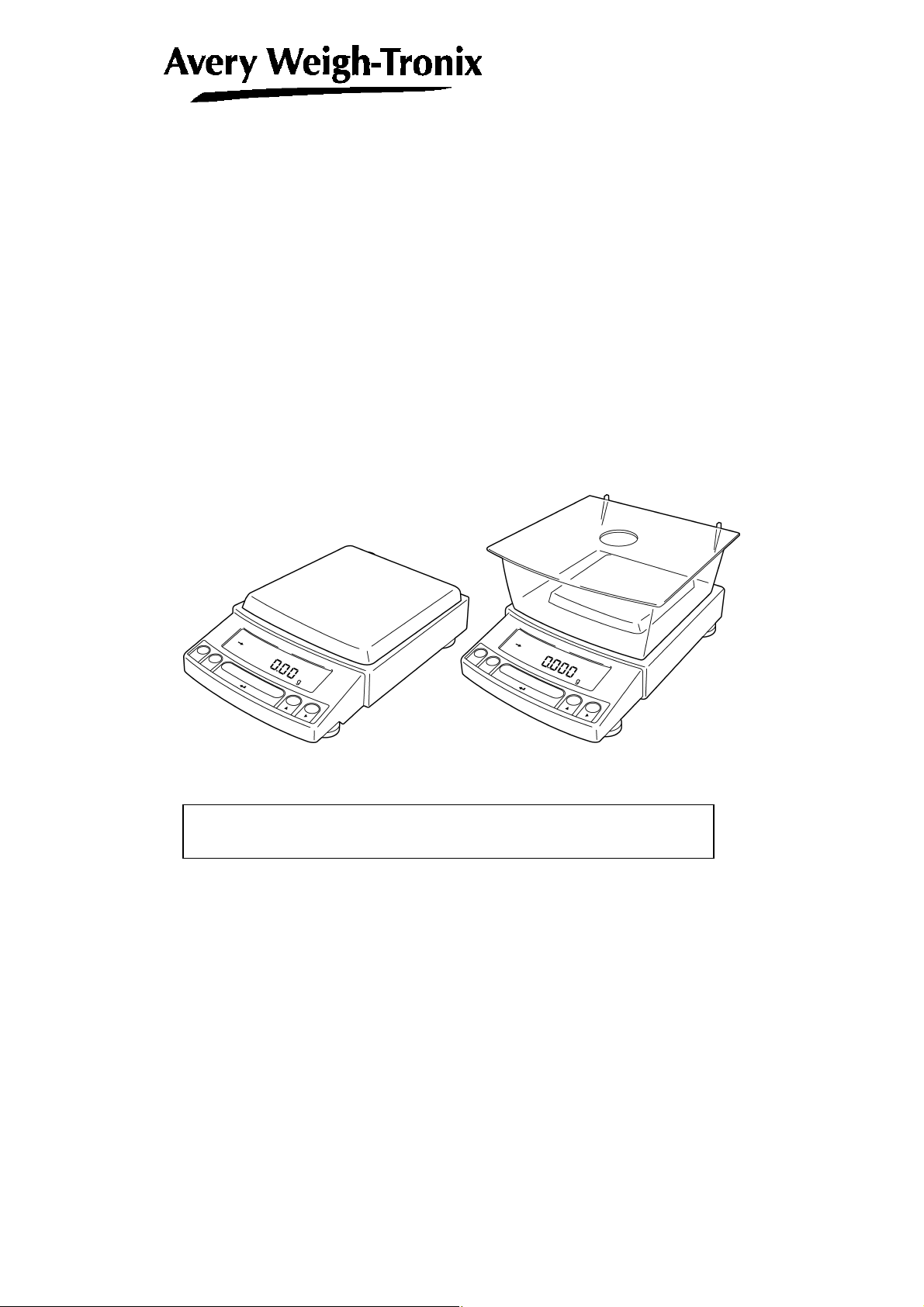
Electronic Balance
User Instructions
Reflex HP Series
Precision Balances
READ AND UNDERSTAND THIS MANUAL BEFORE OPERATION.
76103-918 Issue 1 16-03-2004
English
*76103-918*
dNo.
Notation Conventions
Note
This instruction manual uses the following notation conventions to
indicate Safety Precautions and additional information.
Caution
Note
Indicates a potentially hazardous situation that may
result in injury to personnel or equipment damage.
Provides additional information needed to properly
use the balance.
Other conventions used in this manual include:
Item Description
1, 2, 3 .... Indicates the step number in a procedure or a sequence of changes in the balance display.
[ ] key Indicates the operation key on the balance. See 2.2.
mass display
NO.
Indicates that the balance is in the weighing mode and mass is displayed in one of the weighing
units.
These sections include information to make using the balance more convenient.
Indicates the menu item to be selected.
The number in the is the number of the menu item on the Menu Map. See 7.2 “ Menu Map”.
Notes on the use of verified balances as legal measuring instruments
Important notes about the use of verified balances as legal measuring
instruments in the EU are highlighted with the shadow.
Examples:
Using a verified balance as a legal measuring instrument in the EU:
Not applicable to a verified balance as a legal measuring
instrument in the EU:
There are special requirements on using a verified balance as a legal
measuring instrument in the EU. With the verified balances, some of
the functions are either unavailable or restricted.
"EU" includes the signatories of the European Economic Area
agreement.
- I -
Safety Precautions
Caution
To ensure safe and proper operation of the balance, observe the
following precautions.
• Do not use the balance in hazardous areas.
This includes areas where the balance is exposed to dust or
flammable gases and liquids.
• Use the AC adapter specified by Avery Weigh-Tronix.
To prevent electric shock, never disassemble the AC adapter.
The AC adapter is designed for indoor use. Do not use the AC
adapter in exterior environments or where it may be splashed by
water.
Ensure that the power supply voltage meets the indicated range of
the AC adapter.
• Handle the balance carefully.
The balance is a precision instrument of solid design.
• Do not connect peripheral devices other than those
recommended by Avery Weigh-Tronix.
The balance may not operate properly if peripheral devices other
than those specified in this manual are used. The specifications of
the RS-232C/AUX connector are described in Section 7.6.1.
Connect the peripheral devices according to the methods described
in this instruction manual.
• Do not disassemble the balance, accessories, or peripheral unit.
- II -
Declaration of Conformity
Manufacturer Avery Weigh-Tronix
Type REFLEX MODEL NOs
HPxxxCT
No. of EC type approval certificate T 6426
corresponds to the requirements of the following EC directives:
Non-Automatic Weighing
90/384/EEC1
Instruments
EMC Directive 89/336/EEC
Low Voltage Directive 73/23/EEC
The applicable harmonised
standards are:
EN60950, EN45501, EN55022,
EN55024, EN61000-3
Note 1 : This declaration is only valid if the non–automatic weighing
instrument was verified by the manufacturer or with a certificate
of conformity issued by a notified body.
A copy of the original signed declaration for this instrument is available
from:
Avery Weigh-Tronix, Foundry Lane, Smethwick, West Midlands B66 2LP England
- III -
Declaration of Conformity
Manufacturer Avery Weigh-Tronix
Type REFLEX MODEL NOs
HPxxx/HPxxxC
corresponds to the requirements of the following EC directives:
EMC Directive 89/336/EEC
Low Voltage Directive 73/23/EEC
The applicable harmonised
standards are:
EN60950, EN45501, EN55022,
EN55024, EN61000-3
A copy of the original signed declaration for this instrument is available
from:
Avery Weigh-Tronix, Foundry Lane, Smethwick, West Midlands B66 2LP England
- IV -

Avery Weigh-Tronix Balances and 21 CFR Part 11
21 CFR Part 11
21 CFR Part 11, Electronic Records, Electronic Signatures, Final Rule (often referred to as Part 11)
is the United States Food and Drug Administration (FDA) regulation affecting computer resources
and electronic records that are used for any document that is required to be kept and maintained by
FDA regulations.
Requirements concerning computer resources security are key elements in Part 11.
The controls implemented as a result of security related requirements are intended to result in
trusted records.
Avery Weigh-Tronix CLASS-Balance Agent
Avery Weigh-Tronix provides a means for compliance with 21 CFR Part 11 with Avery Weigh-Tronix
CLASS-Balance Agent software, part of a comprehensive laboratory data management system,
Avery Weigh-Tronix CLASS Agent.
Ask your Avery Weigh-Tronix representative about it.
Avery Weigh-Tronix WindowsDirect
When Avery Weigh-Tronix balances are integrated with laboratory software by means of our
WindowsDirect function, no communication software is required or used.
The Avery Weigh-Tronix balance functions as a primary device in the system, just as a keyboard,
mouse or other data entry hardware does.
For this reason, system validation and compliance may be greatly simplified with the use of Avery
Weigh-Tronix balances.
Two-way Communication
Avery Weigh-Tronix balances have always been computer friendly and they can be set up for
bi-directional communication as part of a fully automated production system or LIMS.
This manual includes the command codes and information needed by programmers to integrate
Avery Weigh-Tronix balances with their software.
- V -

Notation Conventions
Safety Precautions
Declaration Of Conformity
Contents
1. Introduction
・・・・・・・・・・・・・・・・・・・・・・・・・・・・・・・・・・・・・・・・・・・・・・・・・・・・・・
2. Components, Names and Functions
2.1 Components
2.2 Key Panel and Operation
2.3 Balance Display and Functions
・・・・・・・・・・・・・・・・・・・・・・・・・・・・・・・・・・・・・・・・・・・・・・・・・・・・・・・・・・・・・・・・
・・・・・・・・・・・・・・・・・・・・・・・・・・・・・・・・・・・・・・・・・・・・・・・・・・・・・
・・・・・・・・・・・・・・・・・・・・・・・・・・・・・・・・・・・・・・・・・・・・・・・・
・・・・・・・・・・・・・・・・・・・・・・・・・・・・・・・・
3. Specifications
・・・・・・・・・・・・・・・・・・・・・・・・・・・・・・・・・・・・・・・・・・・・・・・・・・・・
4. Installation
4.1 Choosing the Installation Site
4.2 Unpacking and Delivery Inspection
4.3 Installation
4.4 Turning On the Power
4.5 Span Calibration
・・・・・・・・・・・・・・・・・・・・・・・・・・・・・・・・・・・・・・・・・・・・・・・・・・・・・・・
・・・・・・・・・・・・・・・・・・・・・・・・・・・・・・・・・・・・・・・・・・・・・・・・・
・・・・・・・・・・・・・・・・・・・・・・・・・・・・・・・・・・・・・・・・・・・・・
・・・・・・・・・・・・・・・・・・・・・・・・・・・・・・・・・・・・・・・・・・・・・・・・・・・・・・・・・・・・・・・・・・
・・・・・・・・・・・・・・・・・・・・・・・・・・・・・・・・・・・・・・・・・・・・・・・・・・・・・・・・
・・・・・・・・・・・・・・・・・・・・・・・・・・・・・・・・・・・・・・・・・・・・・・・・・・・・・・・・・・・・・
5. Basic Operation ---Read up to this chapter for basic but correct weighing
5.1 Weighing
5.2 Changing the default Unit Display
6. WindowsDirect Function
6.1 Introduction: Experience it!
6.2 Set Up WindowsDirect
6.2.1 Setting Up the Balance
6.2.2 Cable Connection
6.2.3 Setting Up the Computer
6.2.4 Start and Checking Operation
6.3 Troubleshooting
6.4 Notes on WindowsDirect
7. Menu Item Selection
7.1 What is the Menu?
7.2 Menu Map
・・・・・・・・・・・・・・・・・・・・・・・・・・・・・・・・・・・・・・・・・・・・・・・・・・・・・・・・・・・・・・・・・・・
・・・・・・・・・・・・・・・・・・・・・・・・・・・・・・・・・・・・・・・・・・・・・・
・・・・・・・・・・・・・・・・・・・・・・・・・・・・・・・・・・・・・・・・・・
・・・・・・・・・・・・・・・・・・・・・・・・・・・・・・・・・・・・・・・・・・・・・・・・・・・・
・・・・・・・・・・・・・・・・・・・・・・・・・・・・・・・・・・・・・・・・・・・・・・・・・・・・・・・
・・・・・・・・・・・・・・・・・・・・・・・・・・・・・・・・・・・・・・・・・・・・・・・・
・・・・・・・・・・・・・・・・・・・・・・・・・・・・・・・・・・・・・・・・・・・・・・・・・・・・
・・・・・・・・・・・・・・・・・・・・・・・・・・・・・・・・・・・・・・・・・・・・・・
・・・・・・・・・・・・・・・・・・・・・・・・・・・・・・・・・・・・・・・・・・
・・・・・・・・・・・・・・・・・・・・・・・・・・・・・・・・・・・・・・・・・・・・・・・・・・・・・・・・・・・・・
・・・・・・・・・・・・・・・・・・・・・・・・・・・・・・・・・・・・・・・・・・・・・・・・・・・・・
・・・・・・・・・・・・・・・・・・・・・・・・・・・・・・・・・・・・・・・・・・・・・・
・・・・・・・・・・・・・・・・・・・・・・・・・・・・・・・・・・・・・・・・・・・・・・・・・・・・・・・・・・・
・・・・・・・・・・・・・・・・・・・・・・・・・・・・・・・・・・・・・・・・・・・・・・・・・・・・・・・・・・・・・・・・・・
- i -
・・・・・・・・・
1-1
2-1
2-1
2-2
2-3
3-1
4-1
4-1
4-3
4-4
4-7
4-8
5-1
5-1
5-2
6-1
6-1
6-1
6-1
6-2
6-2
6-4
6-5
6-7
7-1
7-1
7-1

7.3 Menu Item Selection Procedure
7.4 Setting Numeric Values
7.5 Related Useful Functions
7.5.1 Last Menu Recall
7.5.2 Returning to the Default Settings (menu reset)
7.5.3 Menu Lock
7.6 Navigating the Menu Map
7.6.1 Specifications of the RS-232C Connector
7.6.2 Table of Unit Conversion Information
・・・・・・・・・・・・・・・・・・・・・・・・・・・・・・・・・・・・・・・・・・・・・・・・・・・・・・
・・・・・・・・・・・・・・・・・・・・・・・・・・・・・・・・・・・・・・・・・・・・・・・・・・・・・・・・・・
・・・・・・・・・・・・・・・・・・・・・・・・・・・・・・・・・・・・・・・・・・・・・・・
・・・・・・・・・・・・・・・・・・・・・・・・・・・・・・・・・・・・・・・・・・・・・・・・・・・・・
・・・・・・・・・・・・・・・・・・・・・・・・・・・・・・・・・・・・・・・・・・・・・・・・・・・・・
・・・・・・・・・・・・・・・・・・・・・・・・・・・・・・・・・・・・・・・・・・・・・・・・・・・・・
8. Built-in Clock Set-up
8.1 Date
8.2 Time
8.3 Setting Display During Stand-by
・・・・・・・・・・・・・・・・・・・・・・・・・・・・・・・・・・・・・・・・・・・・・・・・・・・・・・・・・・・・・・・・・・・・・・・
・・・・・・・・・・・・・・・・・・・・・・・・・・・・・・・・・・・・・・・・・・・・・・・・・・・・・・・・・・・・・・・・・・・・・・・
・・・・・・・・・・・・・・・・・・・・・・・・・・・・・・・・・・・・・・・・・・・・・・
・・・・・・・・・・・・・・・・・・・・・・・・・・・・・・・・・・・・・・・・・・・・・・・
9. Display Settings
9.1 Bar graph display
9.2 Changing the Minimum Display Digit (10d:1d)*
・・・・・・・・・・・・・・・・・・・・・・・・・・・・・・・・・・・・・・・・・・・・・・・・・・
・・・・・・・・・・・・・・・・・・・・・・・・・・・・・・・・・・・・・・・・・・・・・・・・・・・・・・・・・・・・
10. Calibration
10.1 What is calibration?
10.2 Calibration Execution
10.2.1 Span Calibration Using the Built-in Weight (HPxxxC Series Only)
10.2.2 Calibration Check Using the Built-in Weight (HPxxxC Series Only)*
10.2.3 Span Calibration Using External Weights*
10.2.4 Calibration Check Using External Weights*
10.3 Calibration Setting
10.3.1 Selecting the Calibration Type*
10.3.2 PSC Fully-automatic Calibration (HPxxxC series only)
10.3.3 Clock-CAL Fully-automatic Calibration (HPxxxC series only)
10.3.4 PCAL: Calibration of the Built-in Weight (HPxxxC series only)*
10.3.5 PCAL Password Setting (HPxxxC series only)*
10.4 For GLP/GMP/ISO Conformance
10.4.1 Calibration Report Setting
10.4.2 Balance ID Setting
・・・・・・・・・・・・・・・・・・・・・・・・・・・・・・・・・・・・・・・・・・・・・・・・・・・・・・・
・・・・・・・・・・・・・・・・・・・・・・・・・・・・・・・・・・・・・・・・・・・・・・・・・・・・・・・・・・
・・・・・・・・・・・・・・・・・・・・・・・・・・・・・・・・・・・・・・・・・・・・・・・・・・・・・・・・
・・・・・・・・・・・・・・・・・・・・・・・・・・・・・・・・・・・・・・・・・・・・・・・・・・・・・・・・・・・
・・・・・・・・・・・・・・・・・・・・・・・・・・・・・・・・・・・・・・・・・・・・・・
・・・・・・・・・・・・・・・・・・・・・・・・・・・・・・・・・・・・・・・・・・・・・
・・・・・・・・・・・・・・・・・・・・・・・・・・・・・・・・・・・・・・・・・・・・・・・・・・・
11. Environment
11.1 Overview
11.2 Stability and Response (Averaging)
11.3 Stability Detection Band
・・・・・・・・・・・・・・・・・・・・・・・・・・・・・・・・・・・・・・・・・・・・・・・・・・・・・
・・・・・・・・・・・・・・・・・・・・・・・・・・・・・・・・・・・・・・・・・・・・・・・・・・・・・・・・・・・・・・・・・・・
・・・・・・・・・・・・・・・・・・・・・・・・・・・・・・・・・・・・・・・・・・・・
・・・・・・・・・・・・・・・・・・・・・・・・・・・・・・・・・・・・・・・・・・・・・・・・・・・・・・
・・・・・・・・・・・・・・・・・・・・・・・・・・・
・・・・・・・・・・・・・・・・・・・・・・・・・・・・・・・
・・・・・・・・・・・・・・・・・・・・・・・・・・・・・・・・・・・
・・・・・・・・・・・・・・・・・・・・・・・・・・・・・・・・・・
・・・・・・・・・・・
・・・・・・・・・
・・・・・・・・・・・・・・・・・・・・・・・・・・・・・・・
・・・・・・・・・・・・・・・・・・・・・・・・・・・・・・
・・・・・・・・・・・・・・・・・・・・・・・・・・・・・・・・・・・・・・・・・
・・・・・・・・・・・・・・・・・・・・
・・・・・・・・・・・・・・・
・・・・・・・・・・・・・
・・・・・・・・・・・・・・・・・・・・・・・・・・・
7-2
7-4
7-5
7-5
7-5
7-6
7-7
7-12
7-13
8-1
8-1
8-1
8-2
9-1
9-1
9-1
10-1
10-1
10-2
10-2
10-3
10-4
10-5
10-6
10-6
10-6
10-7
10-8
10-9
10-10
10-10
10-10
11-1
11-1
11-1
11-2
- ii -

11.4 Tracking
・・・・・・・・・・・・・・・・・・・・・・・・・・・・・・・・・・・・・・・・・・・・・・・・・・・・・・・・・・・・・・・・・・・・
12. Units
12.1 Unit Display Set-up
12.2 Percentage (%) Conversion
・・・・・・・・・・・・・・・・・・・・・・・・・・・・・・・・・・・・・・・・・・・・・・・・・・・・・・・・・・・・
・・・・・・・・・・・・・・・・・・・・・・・・・・・・・・・・・・・・・・・・・・・・・・・・・・・・・・・・・・
・・・・・・・・・・・・・・・・・・・・・・・・・・・・・・・・・・・・・・・・・・・・・・・・・・・
13. Enhancing Productivity
13.1 Checkweighing and Target Display
13.1.1 Checkweighing (Comparator) Display Type 1
13.1.2 Checkweighing (Comparator) Display Type 2
13.1.3 Target Mode
13.2 Piece Counting (PCS)
13.3 Auto Print
13.4 Auto Zero*
13.5 Zero Range
13.6 Taring/Printing at Stability*
13.7 Pretaring Value*
・・・・・・・・・・・・・・・・・・・・・・・・・・・・・・・・・・・・・・・・・・・・・・・・・・・・・・・・・・・・・・・・・・・
・・・・・・・・・・・・・・・・・・・・・・・・・・・・・・・・・・・・・・・・・・・・・・・・・・・・・・・・・・・・・・・・・・
・・・・・・・・・・・・・・・・・・・・・・・・・・・・・・・・・・・・・・・・・・・・・・・・・・・・・・・・・・・・・・・・・
・・・・・・・・・・・・・・・・・・・・・・・・・・・・・・・・・・・・・・・・・・・・・・・・・・・・・・・・・・・・・
14. Application Functions
14.1 Solid Specific Gravity Measurement
14.2 Liquid Density Measurement
14.3 Peak Hold*
14.4 Interval Timer*
14.5 Auto-Memory and Zeroing*
14.6 Animal Weighing*
・・・・・・・・・・・・・・・・・・・・・・・・・・・・・・・・・・・・・・・・・・・・・・・・・・・・・・・・・・・・・・・・・
・・・・・・・・・・・・・・・・・・・・・・・・・・・・・・・・・・・・・・・・・・・・・・・・・・・・・・・・・・・・・・
・・・・・・・・・・・・・・・・・・・・・・・・・・・・・・・・・・・・・・・・・・・・・・・・・・・・・・・・・・・・
・・・・・・・・・・・・・・・・・・・・・・・・・・・・・・・・・・・・・・・・・・・
・・・・・・・・・・・・・・・・・・・・・・・・・・・・・・・・・・・・・・・・・・・・
・・・・・・・・・・・・・・・・・・・・・・・・・・・・・・・・・・・・・・・・・・・・・・・・・・・・・・・・・
・・・・・・・・・・・・・・・・・・・・・・・・・・・・・・・・・・・・・・・・・・・・・・・・・・・・・・・・
・・・・・・・・・・・・・・・・・・・・・・・・・・・・・・・・・・・・・・・・・・・・・・・・・・・・
・・・・・・・・・・・・・・・・・・・・・・・・・・・・・・・・・・・・・・・・・・・・・
・・・・・・・・・・・・・・・・・・・・・・・・・・・・・・・・・・・・・・・・・・・・
・・・・・・・・・・・・・・・・・・・・・・・・・・・・・・・・・・・・・・・・・・・・・・・・・・
・・・・・・・・・・・・・・・・・・・・・・・・・・・・・・・・・・・・・・・・・・・・・・・・・・・
15. Connecting Peripheral Instruments
15.1 Electronic Printer
15.2 Personal Computer - RS-232C -
15.2.1 Connecting the Cable
15.2.2 Data Format
15.2.3 Using Command Codes
15.2.4 Multi-Connection Mode
15.3 Communication Setting
15.3.1 Overview
15.3.2 Handshaking
15.3.3 Format
15.3.4 Communication Speed
15.3.5 Parity / Bit Length
15.3.6 Stop Bit
15.3.7 Delimiter
・・・・・・・・・・・・・・・・・・・・・・・・・・・・・・・・・・・・・・・・・・・・・・・・・・・・・・・・・・・・
・・・・・・・・・・・・・・・・・・・・・・・・・・・・・・・・・・・・・・・・・・・・・・・
・・・・・・・・・・・・・・・・・・・・・・・・・・・・・・・・・・・・・・・・・・・・・・・・・
・・・・・・・・・・・・・・・・・・・・・・・・・・・・・・・・・・・・・・・・・・・・・・・・・・・・・・・・・
・・・・・・・・・・・・・・・・・・・・・・・・・・・・・・・・・・・・・・・・・・・・・・・
・・・・・・・・・・・・・・・・・・・・・・・・・・・・・・・・・・・・・・・・・・・・・・・
・・・・・・・・・・・・・・・・・・・・・・・・・・・・・・・・・・・・・・・・・・・・・・・・・・・・・・・
・・・・・・・・・・・・・・・・・・・・・・・・・・・・・・・・・・・・・・・・・・・・・・・・・・・・・・・・・・・・
・・・・・・・・・・・・・・・・・・・・・・・・・・・・・・・・・・・・・・・・・・・・・・・・・・・・・・・・
・・・・・・・・・・・・・・・・・・・・・・・・・・・・・・・・・・・・・・・・・・・・・・・・・・・・・・・・・・・・・・
・・・・・・・・・・・・・・・・・・・・・・・・・・・・・・・・・・・・・・・・・・・・・・・・
・・・・・・・・・・・・・・・・・・・・・・・・・・・・・・・・・・・・・・・・・・・・・・・・・・・・
・・・・・・・・・・・・・・・・・・・・・・・・・・・・・・・・・・・・・・・・・・・・・・・・・・・・・・・・・・・・・
・・・・・・・・・・・・・・・・・・・・・・・・・・・・・・・・・・・・・・・・・・・・・・・・・・・・・・・・・・・・
・・・・・・・・・・・・・・・・・・・・・・・・・・・・
・・・・・・・・・・・・・・・・・・・・・・・・・・・・
・・・・・・・・・・・・・・・・・・・・・・・・・・・・・・・・
11-2
12-1
12-1
12-2
13-1
13-1
13-2
13-2
13-3
13-4
13-5
13-6
13-6
13-7
13-8
14-1
14-1
14-3
14-5
14-6
14-7
14-8
15-1
15-1
15-2
15-2
15-3
15-4
15-9
15-12
15-12
15-12
15-13
15-13
15-13
15-13
15-14
- iii -

16. Maintenance and Transportation
16.1 Maintenance
16.2 Moving the Balance
17. Troubleshooting
17.1 General Display
17.2 Error Display
17.3 Troubleshooting
17.4 LCD (Liquid Crystal Display) Check
・・・・・・・・・・・・・・・・・・・・・・・・・・・・・・・・・・・・・・・・・・・・・・・・・・・・・・・・・・・・・・・・
・・・・・・・・・・・・・・・・・・・・・・・・・・・・・・・・・・・・・・・・・・・・・・・・・・・・・・・・・・
・・・・・・・・・・・・・・・・・・・・・・・・・・・・・・・・・・・・・・・・・・・・・・・・・・
・・・・・・・・・・・・・・・・・・・・・・・・・・・・・・・・・・・・・・・・・・・・・・・・・・・・・・・・・・・・・
・・・・・・・・・・・・・・・・・・・・・・・・・・・・・・・・・・・・・・・・・・・・・・・・・・・・・・・・・・・・・・・・
・・・・・・・・・・・・・・・・・・・・・・・・・・・・・・・・・・・・・・・・・・・・・・・・・・・・・・・・・・・・・
・・・・・・・・・・・・・・・・・・・・・・・・・・・・・・・・・・・
・・・・・・・・・・・・・・・・・・・・・・・・・・・・・・・・・・・・・・・・・・・・
16-1
16-1
16-1
17-1
17-1
17-2
17-3
17-3
- iv -

1. Introduction
The Avery Weigh-Tronix Reflex HP series of precision balances give you high performance, fast
response, and durability. Features available include multiple units of measure, piece counting,
checkweighing functions, auto print, and GLP/GMP/ISO output including date and time data from a
built-in clock.
The Reflex HP series also features Avery Weigh-Tronix’s WindowsDirect communication, which
requires no software installation to quickly integrate balances with laboratory or business software. This
function eliminates data input errors and offers extensive flexibility for application development without
compromising compliance or data security.
The Reflex HP series balance incorporates a motor-driven built-in calibration weight that can
automatically calibrate sensitivity without the use of external weights.
Read this manual carefully before using this instrument and keep it with the balance for future reference.
This manual refers to the different types of Reflex HP series balance as follows:
HPxxx
HPxxxC
HPxxxCT
Where: xxx indicates capacity of balance (g)
C indicates built in calibration
T indicates EC Type Approval
The type of balance is classified as “large pan” or “small pan” depending on the size of the pan.
Large pan type: Balance model with a capacity of 2200g or more.
Small pan type: Balance model with a capacity of 820g or less.
1 - 1

© Avery Berkel Limited 2004. All rights reserved.
The information contained herein is the property of Avery Berkel Limited and is supplied without liability
for errors or omissions. No part may be reproduced or used except as authorised by contract or other
written permission. The copyright and the foregoing restriction on reproduction and use extend to all
media in which the information may be embodied.
Trademarks and acknowledgements
Avery, Avery Berkel, Avery Weigh-Tronix are registered trademarks in certain jurisdictions and owned
and registered by companies within the Avery Weigh-Tronix Group.
All brands and product names used within this document are trademarks or registered trademarks of
their respective holders.
IMPORTANT
When programming or configuring the equipment you must ensure that you comply with all relevant
standards and legislation. The example settings given in this book may not be legal for trade with the
public.
1 - 2
2. Components, Names & Functions
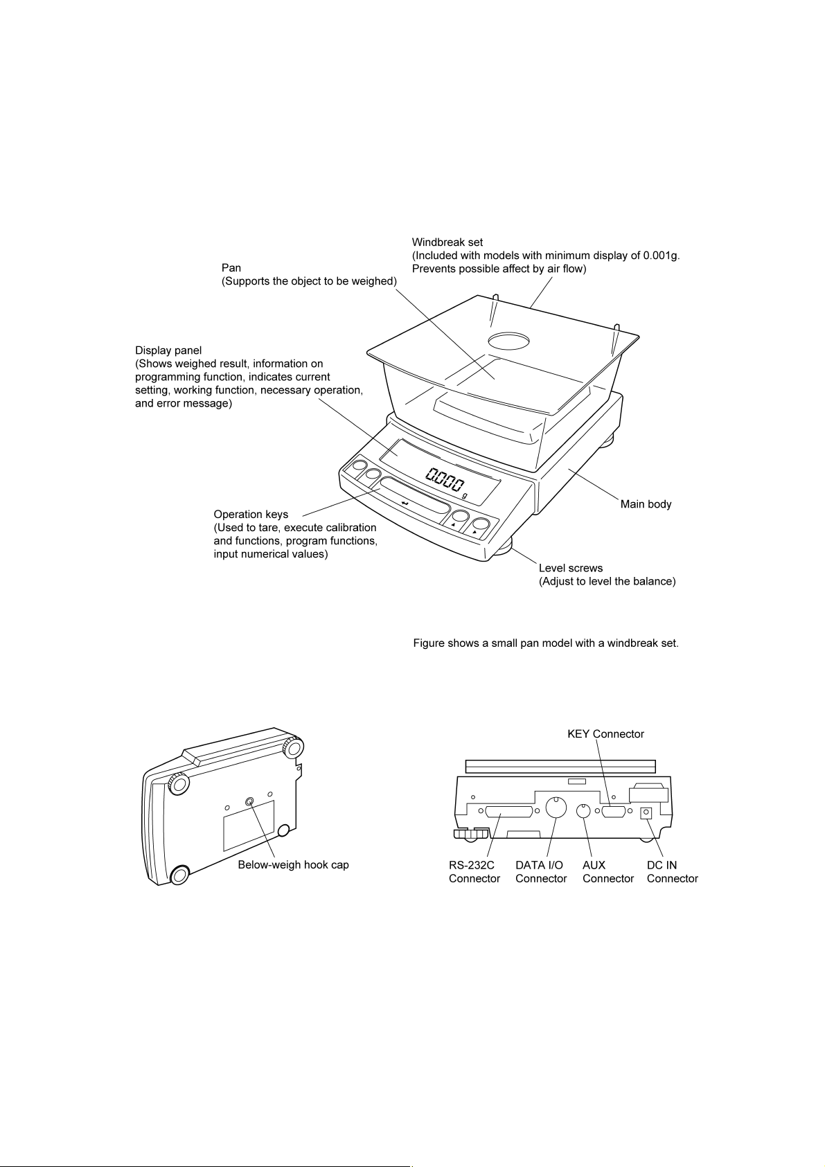
2.1 Components
2 - 1
(Connectors on the back)
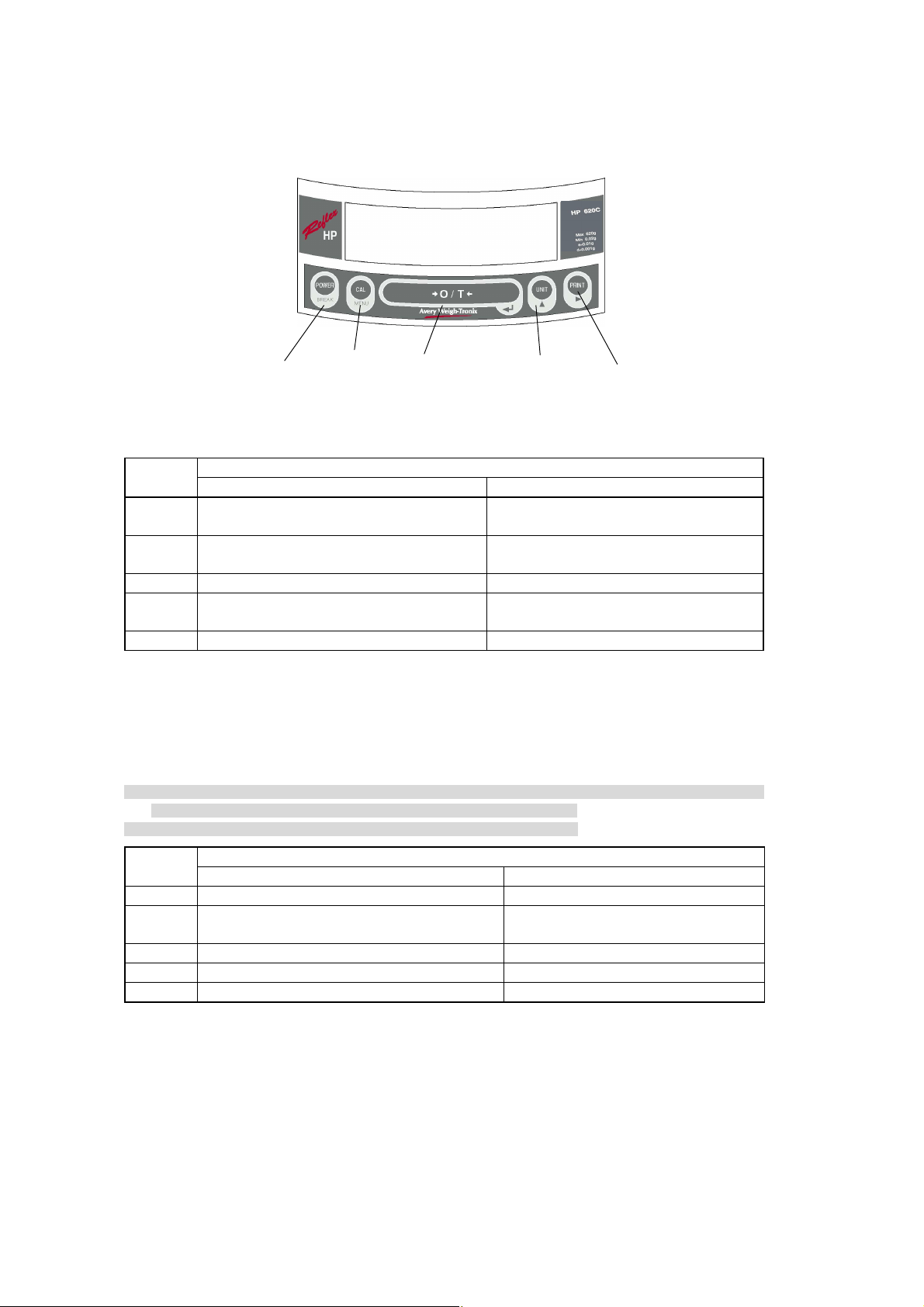
2.2 Key Panel and Operation
[POWER] key [CAL] key [O/T] key [UNIT] key [PRINT] key
Function of the keys
Key
[POWER]
[CAL]
[O/T] Tares the balance. (Displays zero.) (*2)(*5) Displays the Pretare value.(*6)
[UNIT]
[PRINT] Sends the displayed value to a peripheral device. Sends the date and time to a peripheral device.
*1 This key is used to set values when percent (%), number (PCS), solid specific gravity (▼d), or liquid specific
gravity (d) are displayed.
*2 When a Pretare value is set, zero is not displayed and [- Pretare value] is displayed.(*6)
*3 Units other than “g” must be set up before they can be used for measurement. Only gram (g), percent (%), and
piece counting (PCS) are set-up before shipment. To set up other units or specific gravity measurement, refer to
section 12., or 14.1, 14.2.
*4 When the unit is set to 10d, the resolution of the minimum display is decreased by one decimal place.
*5 Either "Taring" (at a weight exceeding 2.5% of the capacity) or "Zeroing" (at a weight within 2.5% of the capacity)
takes place with a verified balance as a legal measuring instrument in the EU.
*6 Not applicable to a verified balance as a legal measuring instrument in the EU.
Key
[POWER] Returns to the previous menu level Returns to the mass display.
[CAL] Moves to the next menu item.
[O/T] Selects and sets the currently displayed menu item. No operation.
[UNIT] Increases the numeric value of the blinking digit by 1. No operation.
[PRINT] Moves to the next digit during numeric value entry. No operation.
Switches between the operation and standby
modes.
Enters span calibration or menu item selection.
(*1)
Changes the weighing unit or selects specific
gravity measurement. (*3)
Press Once and Release Press and Hold for About 3 Seconds
Press Once and Release Press and Hold for About 3 Seconds
During Weighing
Exits the application function and returns to the
mass display.
Displays the last menu item that was set.
(Last menu recall)
Switches between the 1d and 10d display. (*4)
(*6)
During Menu Item Selection
Displays the last menu item that was set.
(Last Menu Recall)
2 - 2
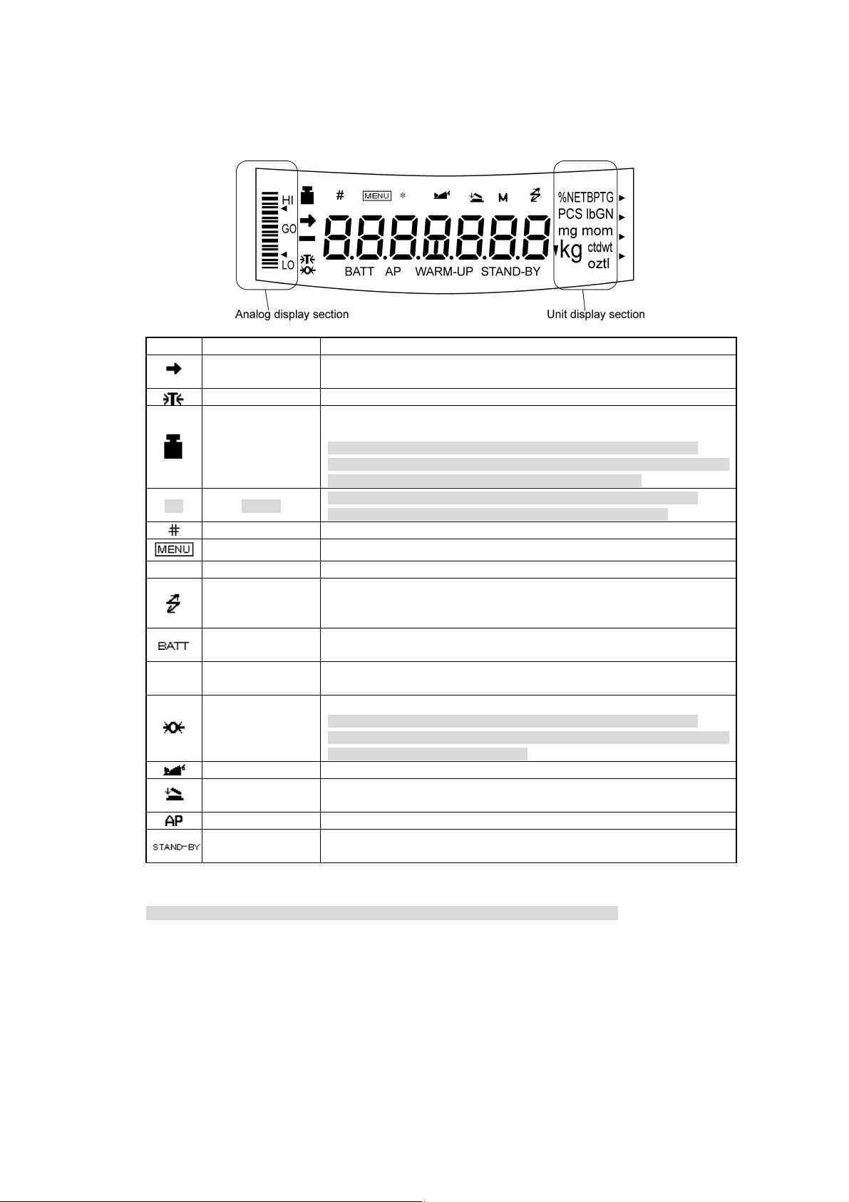
2.3 Balance Display and Functions
Display Name Description
Stability mark
[ ] Bracket
Number symbol Indicates numeric value entry.
* Asterisk Indicates that the displayed numeric value is not a mass value.
▼ inverse triangle symbol
Zero symbol
Animal symbol Indicates the set-up of Animal Weighing function.(*2)
Auto Print symbol Indicates the set-up of Auto Print function.
*1 Stability symbol
The displayed value may change while the stability symbol remains illuminated if the load is changing slowly or if
the stability detection band has been set to a large value.
Tare symbol Indicates that a Pretare value has been set.(*2)
Weight symbol
Menu symbol Indicates that the menu lock is on. Illuminates during menu item selection.
Communication
symbol
Battery symbol
Auto-Memory &
Zeroing symbol
Stand-by symbol
Indicates that the weighed value is stable. (*1) In menu item selection, indicates
currently selected item.
Illuminates during span calibration. In menu selection, indicates setting related
to calibration. Blinks before automatic span calibration starts.
Note: Using a verified balance as a legal measuring instrument in the EU:
When automatic span calibration is not activated, operator must carry out span
calibration with the built-in weight upon blinking of this symbol.
Note: Using a verified balance as a legal measuring instrument in the EU:
The figure bordered by the bracket is the auxiliary indicating device.
Illuminates during communication to external equipment through the RS-232C
or DATA I/O connector. In menu selection, indicates setting related to
communication.
When the balance is operated with the optional battery pack, this symbol
illuminates to indicate that the battery voltage has dropped.
Indicates the set-up of solid specific gravity measurement. Used as a substitute
for the decimal point.
Indicates the set-up of Auto Zero function.(*2)
Note: Using a verified balance as a legal measuring instrument in the EU:
Indicates that the balance is set exactly to "Zero" with the zero-setting function
(+-0.25e: e = verification scale interval).
Indicates the set-up of Auto-Memory and Zeroing.(*2)
Illuminates when the balance power is in the standby mode.
Also illuminates when the application function has entered the standby mode.
*2 Not applicable to a verified balance as a legal measuring instrument in the EU
2 - 3
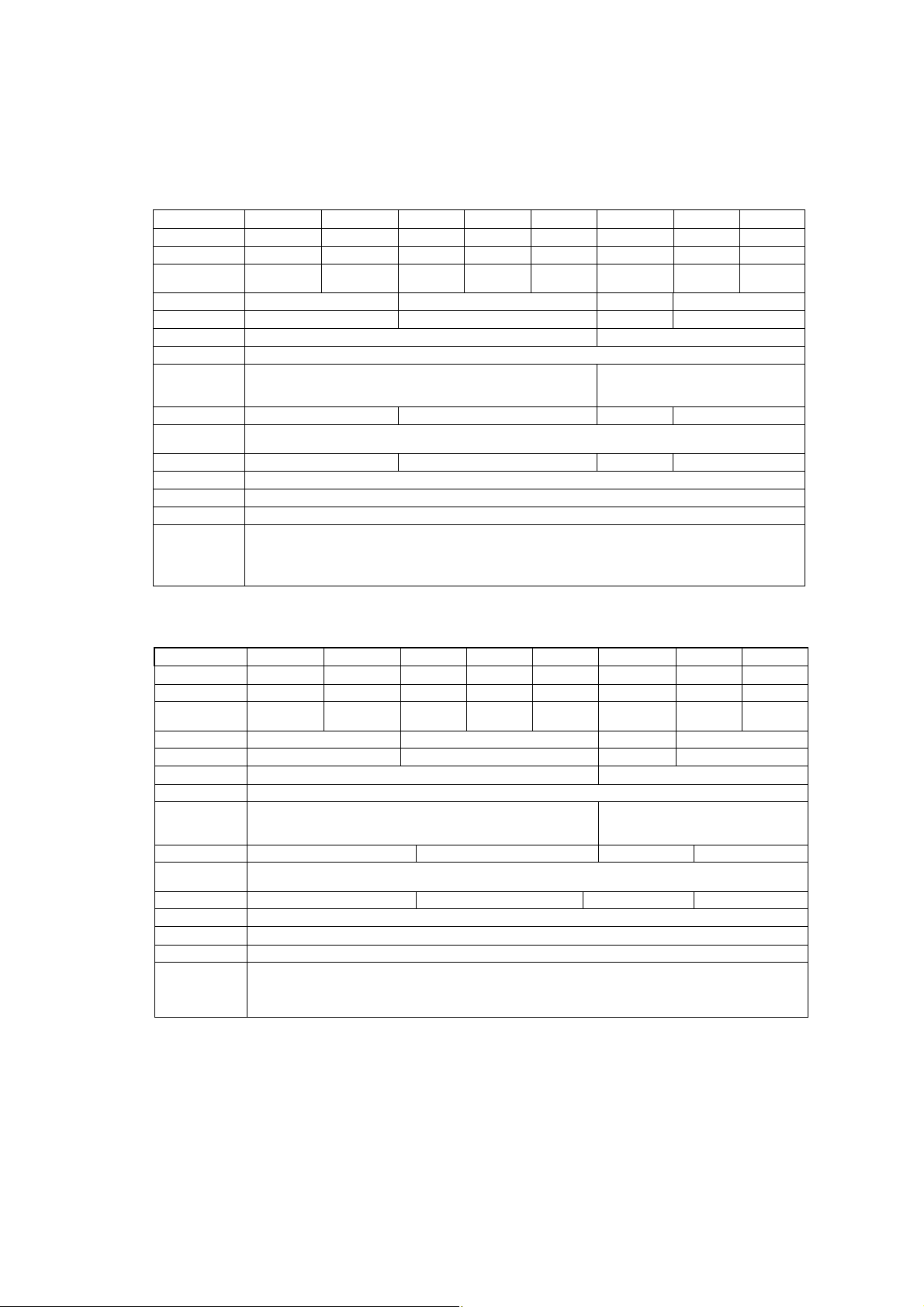
3. Specifications
Reflex HP Series with internal Calibration
HP Series Model HP420C HP620C HP2200C HP4200C HP6200C HP820C HP4200SC HP8200C
Capacity 420g 620g 2200g 4200g 6200g 820g 4200g 8200g
Minimum display 0.001g 0.001g 0.01g 0.01g 0.01g 0.01g 0.1g 0.1g
Calibration range
with external weights
Repeatability (σ) ≤0.001g ≤0.01g ≤0.008g ≤0.08g
Linearity ±0.002g ±0.02g ±0.01g ±0.1g
Response time (s) 1.5 - 2.5 0.7 - 1.2
Ambient temperature (°C)
Temperature coefficient
of sensitivity (ppm/°C)
(10 - 30°C)
Pan size (mm) approx.
Main body dimensions
(mm) approx.
Weight (kg) approx. 3.4 4.6 3.4 4.6
Display LCD with backlight
Power requirement 12V 1A
Data I/O RS-232C
100 - 420g 100 - 620g 1000 - 2200g 1000 - 4200g 1000 - 6200g 100 - 820g 1000 - 4200g 1000 - 8200g
5 - 40
±3 ±5
108×105 170×180 108×105 170 X 180
190W×317D×78H
Features
WindowsDirect, Clock-CAL, GLP/GMP/ISO conformance, Analog display, % display, PCS, User unit, Animal weighing,
Specific gravity measurement S/W, Checkweighing
Reflex HP Series with external Calibration
HP Series Model HP420 HP620 HP2200 HP4200 HP6200 HP820 HP4200S HP8200
Capacity 420g 620g 2200g 4200g 6200g 820g 4200g 8200g
Minimum display 0.001g 0.001g 0.01g 0.01g 0.01g 0.01g 0.1g 0.1g
Calibration range
with external weights
Repeatability (σ) ≤ 0.001g ≤0.01g ≤0.008g ≤0.08g
Linearity ± 0.002g ±0.02g ±0.01g ±0.1g
Response time (s) 1.5 - 2.5 0.7 - 1.2
Ambient temperature (°C)
Temperature coefficient
of sensitivity (ppm/°C)
(10 - 30°C)
Pan size (mm) approx. 108 × 105 170 × 180 108×105 170×180
Main body dimensions
(mm) approx.
Weight (kg) approx. 2.7 2.9 2.7 2.9
Display LCD with backlight
Power requirement 12V 1A
Data I/O RS-232C
Features
100 - 420g 100 - 620g 1000 - 2200g 1000 - 4200g 1000 - 6200g 100 - 820g 1000 - 4200g 1000 - 8200g
5 - 40
±3 ±5
190W × 317D × 78H
WindowsDirect, GLP/GMP/ISO conformance, Analog display, % display, PCS, User unit, Animal weighing,
Specific gravity measurement S/W, Checkweighing
3 - 1
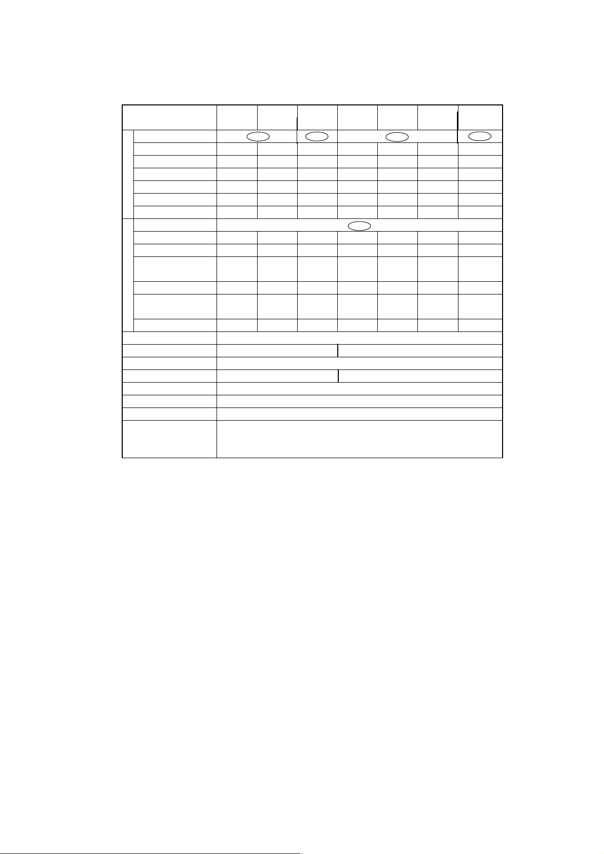
Reflex HP Series – EC Trade approved
with internal Calibration
Reflex HP Series
Trade Approved Models
Accuracy class Ⅱ Ⅰ Ⅱ Ⅰ
Capacity 820g 420g 620g 8200g 2200g 4200g 6200g
Verification scale interval (e) 0.1g 0.01g 0.01g 1g 0.1g 0.1g 0.1g
g
Number of verification scale interval
Scale interval (d) 0.01g 0.001g 0.001g 0.1g 0.01g 0.01g 0.01g
Range of use 0.5g-820g 0.02g-420g 0.02g-620g 0.1g-8220g 5g-2200g 0.5g-4200g 0.5g-6200g
Tare range (by subtraction) -820g -420g -620g -8200g -2200g -4200g -6200g
Accuracy class Ⅱ
Capacity N/A 2100ct 3100ct N/A 11000ct 21000ct 31000ct
Verification scale interval (e) N/A 0.1ct 0.1ct N/A 1ct 1ct 1ct
Number of verification scale
ct
interval
Scale interval (d) N/A 0.01ct 0.01ct N/A 0,1ct 0.1ct 0.1ct
Range of use
Tare range (by subtraction) N/A -1100ct -3100ct N/A -11000ct -21000ct -31000ct
Ambient operating temperature(°C) 10 - 30
Pan size (mm) approx. 108 × 105 170x180
Main body dimensions (mm) approx. 190W × 317D × 78H
Weight (kg) approx. 3.4 4,6
Display LCD with backlight
Power consumption DC12V, 1A
Data I/O RS-232C
HP820CT HP420CT HP620CT HP8200CT HP2200CT HP4200CT HP6200CT
8200 42000 62000 8200 22000 42000 62000
N/A 21000 31000 N/A 11000 21000 31000
N/A
0.2ct-2100ct 0.2ct-3100ct
N/A
N/A
5ct-11000ct 5ct-21000ct 5ct-31000ct
N/A
Features
WindowsDirect, PSC, Clock-CAL, GLP/GMP/ISO conformance, Analog display, % display, PCS,
Specific gravity measurement S/W, Checkweighing
3 - 2

4. Installation
4.1 Choosing the Installation Site
(1) Power supply
• Select an installation site that is near a power source to ensure that the attached AC adapter is
used properly. If this is not possible, an optional battery pack is available as a special accessory.
• Verify that the supply power voltage conforms to that indicated on the AC adapter.
(2) Installation site
Caution
Avoid sites where the balance will be exposed to the following:
• Air flow from air-conditioner, open window, or
ventilator
• Vibration
• Direct sunlight
4 - 1
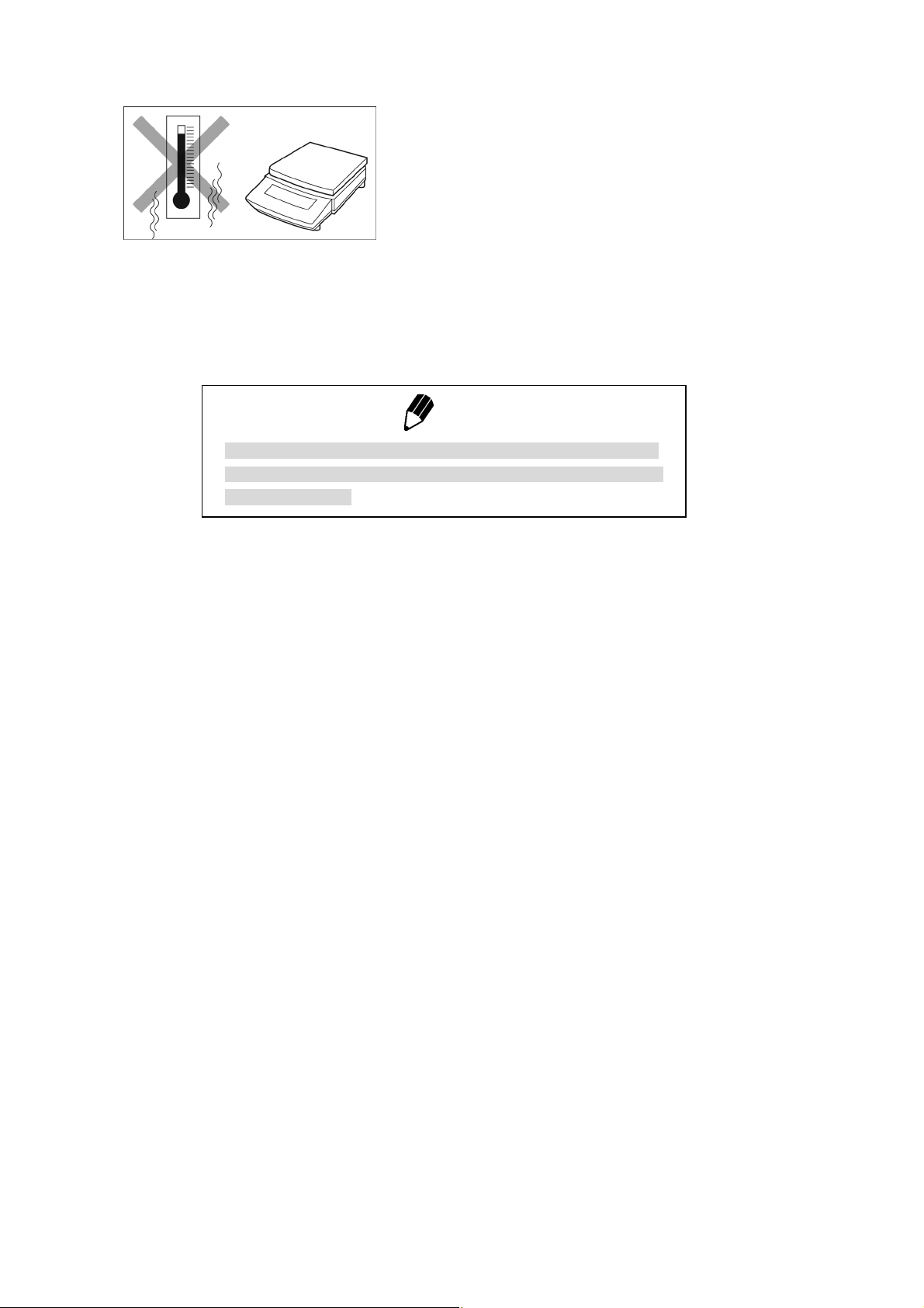
• Extreme temperature, temperature changes or
humidity
• Corrosive or flammable gasses
´ • Dust,wind, electromagnetic waves, or magnetic
fields fields
Note
Using a verified balance as a legal measuring instrument in the EU:
The balance must be used within the temperature range indicated on
the verification label.
4 - 2
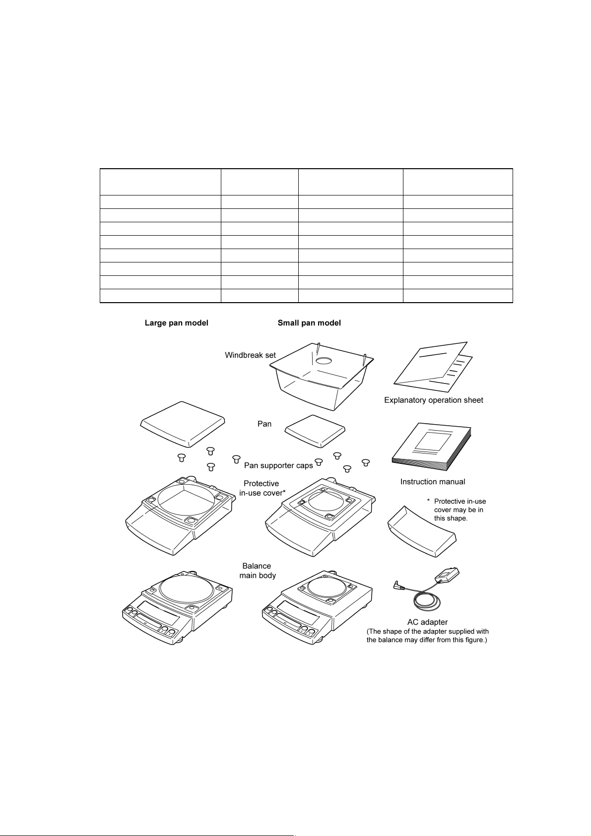
4.2 Unpacking and Delivery Inspection
Unpack and remove all the items from the delivery box. Check if all the listed items are present and
nothing has been damaged. Contact your local sales representative in case of damaged or missing
items.
Standard Packing List (Number of item)
Large pan model
Balance main body 1 1 1
Pan support cap 4 4 4
Pan 1 1 1
AC adapter 1 1 1
Protective in-use cover 1 1 1
Windbreak set 0 0 1
Instruction manual 1 1 1
Explanatory operation sheet 1 1 1
Small pan model
(Minimum display 0.01g)
Small pan model
(Minimum display 0.001g)
4 - 3
4.3 Installation
(Start at step 3 when installing a HP (external calibration) series balance. You will need a Pozidrive
screw driver for a HPxxxC (internal calibration) series balance.)
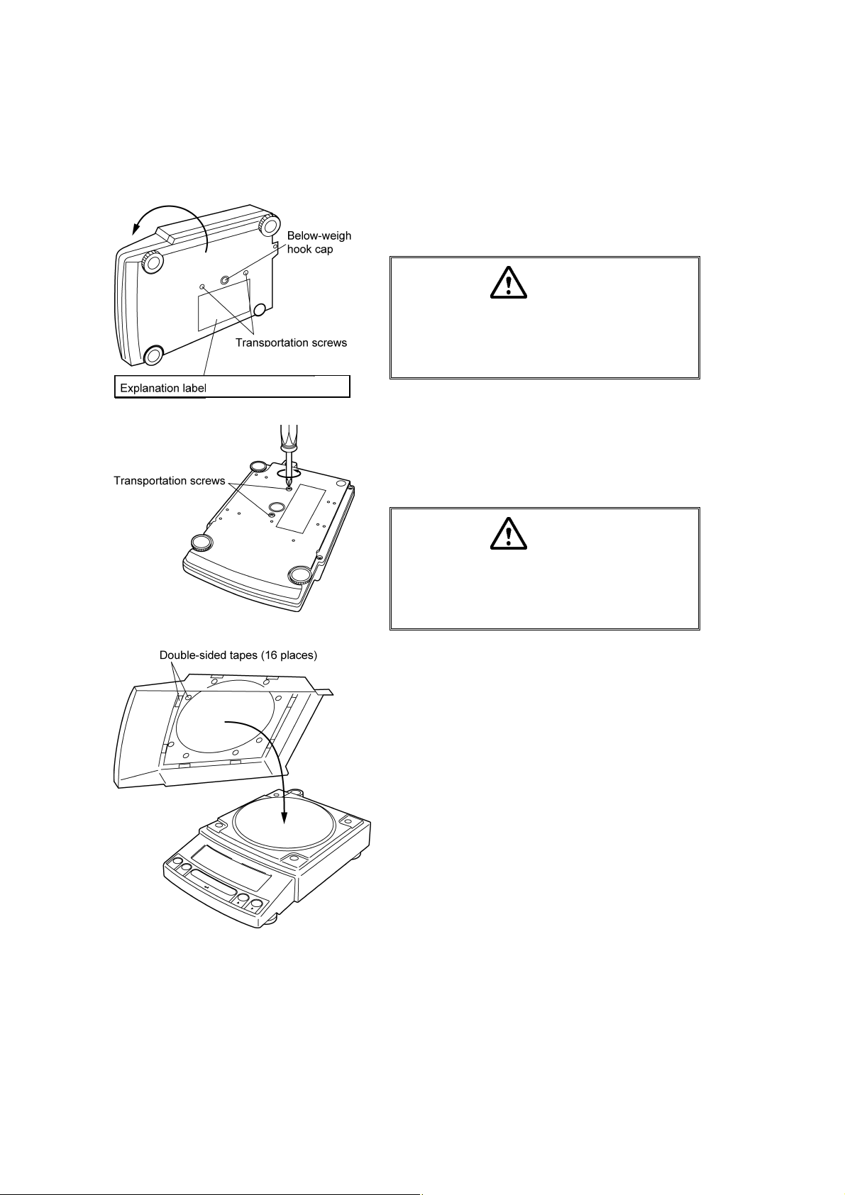
1 Place the balance main body upside down.
(HPxxxC only)
only for HPxxxC series
(only for HPxxxC series)
Caution
Do not operate step 2 with the balance placed
on its side.
Place the balance on a smooth surface.
2 Referring to the explanation label on the bottom of
the balance, turn the two transportation screws
counterclockwise until they tighten again. (HPxxxC
only)
Caution
When moving the balance again, turn the two
transportation screws clockwise until they
tighten. (HPxxxC only)
3 If you install the protective in-use cover, remove the
paper to expose the double-sided tapes on it and
place it on the balance main body. Press firm so
that the cover does not touch the pan.
[Large pan model]
[The shape of the protective in-use cover may be
different (See 4.2).]
4 - 4
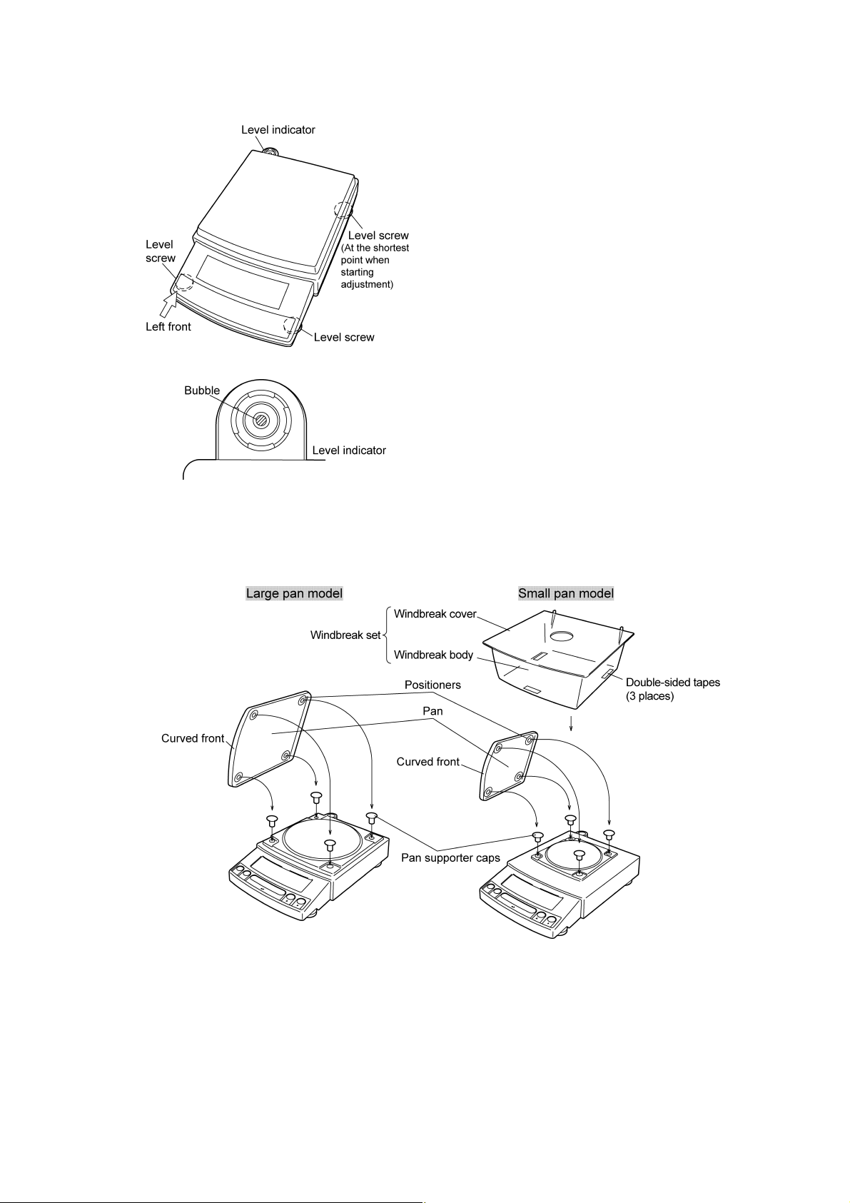
4 Adjust the level.
This balance has four feet, three of which are
adjustable. For efficient level adjustment, follow the
procedure below.
(1) First, verify that all three leveling screws are at
their shortest point.
(2) While lightly pressing down on the left front of the
balance, turn both of the front leveling screws to
bring the air bubble into the center circle of the
level indicator.
(3) Finally, while still pressing down on the front of
the balance, adjust the leveling screw at the right
rear of the balance until the balance is stable.
5 Insert the four pan supporter caps into the holes in
the top of the balance. Place the pan on top of them.
Positioners of the pan must fit pan supporter caps in
this operation.
6 Before mounting the windbreak, remove the paper
to expose the double-sided tapes on it. Attach the
windbreak to the top of the balance. The windbreak
is a standard accessory for models with a minimum
display of 0.001g.
4 - 5

Note
Using a verified balance as a legal measuring instrument in the EU:
Legal regulations require a verified balance to be sealed. This control
seal is a self-destructive adhesive label. If you attempt to remove it, this
seal is irreparably damaged thereby invalidating the verification. The
balance must then be re-verified before it is used for legal
measurements.
4 - 6
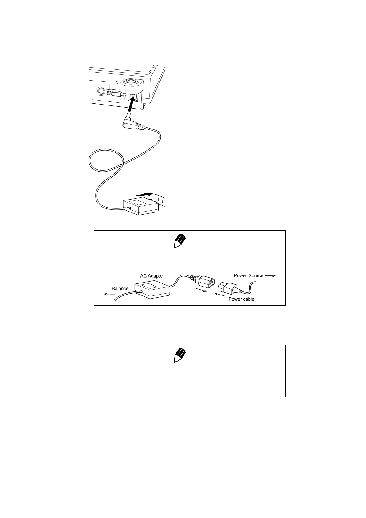
4.4 Turning On the Power
1 Insert the plug of the AC adapter into the DC IN
connector on the rear of the balance.
2 Insert the AC adapter into the power source. The
balance self-check is activated and the following
messages are displayed in the order indicated.
[HELLo], [CHE 5], [CHE 4], [CHE 3], [CHE2],
[CHE1], [CHE0], whole lighting, [oFF] ([CHE 5] and
[CHE 4] are not displayed for the HPxxx series).
Note
A power cable may be necessary to connect the AC adapter to the
power source, depending on the type of the AC adapter.
3 Press [POWER] key. The whole display illuminates
Note
When using the optional battery pack (special accessory), connect the
fully charged battery pack to the DC IN connector of the balance using
the cable attached to the battery pack.
and then the display changes to indicate the
gram-display. The backlight is illuminated.
4 - 7
4.5 Span Calibration
Using a verified balance as a legal measuring instrument in the EU:
Span calibration must be performed once the balance is installed and
before using the balance as a legal measuring instrument in the EU.
Span calibration must be performed with the internal calibration weight
to maintain the verification valid. The balance must be connected to
power and warmed up for at least 2 hours prior to span calibration and
use as a legal measuring instrument.
It is necessary to calibrate the balance after it is moved.
Verify that the balance is stable before performing the span calibration. To achieve a very stable state,
ensure that the balance has been turned on with the gram-display for at least two hours, that the
temperature is constant, that there are no breezes or vibrations and that the balance is in an area
isolated from the normal traffic flow.
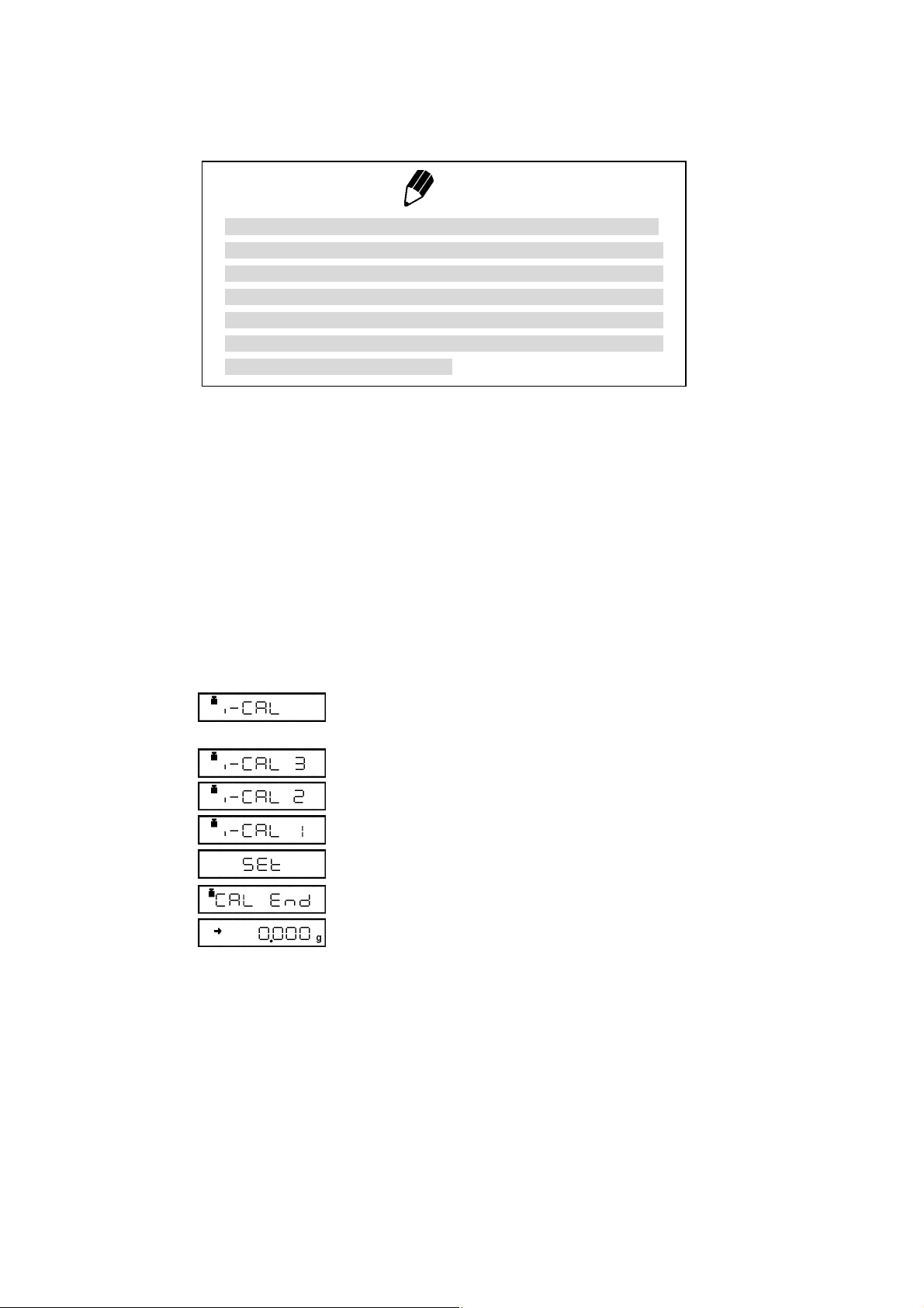
HPxxxC series [Span Calibration Using the Built-in
Weight]
1 Verify that the balance is in gram-display and that
Note
the pan is empty.
2 Press the [CAL] key once. “i-CAL” displayed.
3 Press the [O/T] key. After “i-CAL3” ... “i-CAL1”,
“Set”, “CALEnd” are displayed indicating the
completion of span calibration, the gram-display will
appear.
This is the standard calibration type. Refer to 10.3.1 for use of external weights.
4 - 8
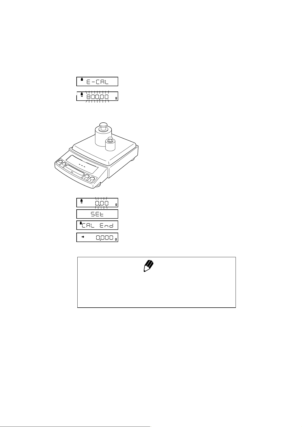
(Example)
HP series [Span Calibration Using External Weights]
1 Verify that the balance is in gram-display and
unload the sample from the pan.
2 Press the [CAL] key once. “E-CAL” is displayed.
3 Press the [O/T] key.
The value of the correct calibration weight to be
loaded is displayed and blinks.
4 Load the indicated calibration weight and press the
[O/T] key.
5 When the zero display blinks, unload the weight
from the pan and press the [O/T] key. “Set” is
displayed briefly to indicate completion of span
calibration. Then the gram-display will return.
Span calibration is required again :
when the location of the balance is changed,
•
when the room temperature changes considerably,
•
periodically, according to the quality control plan of the user.
•
Note
4 - 9
5. Basic Operation
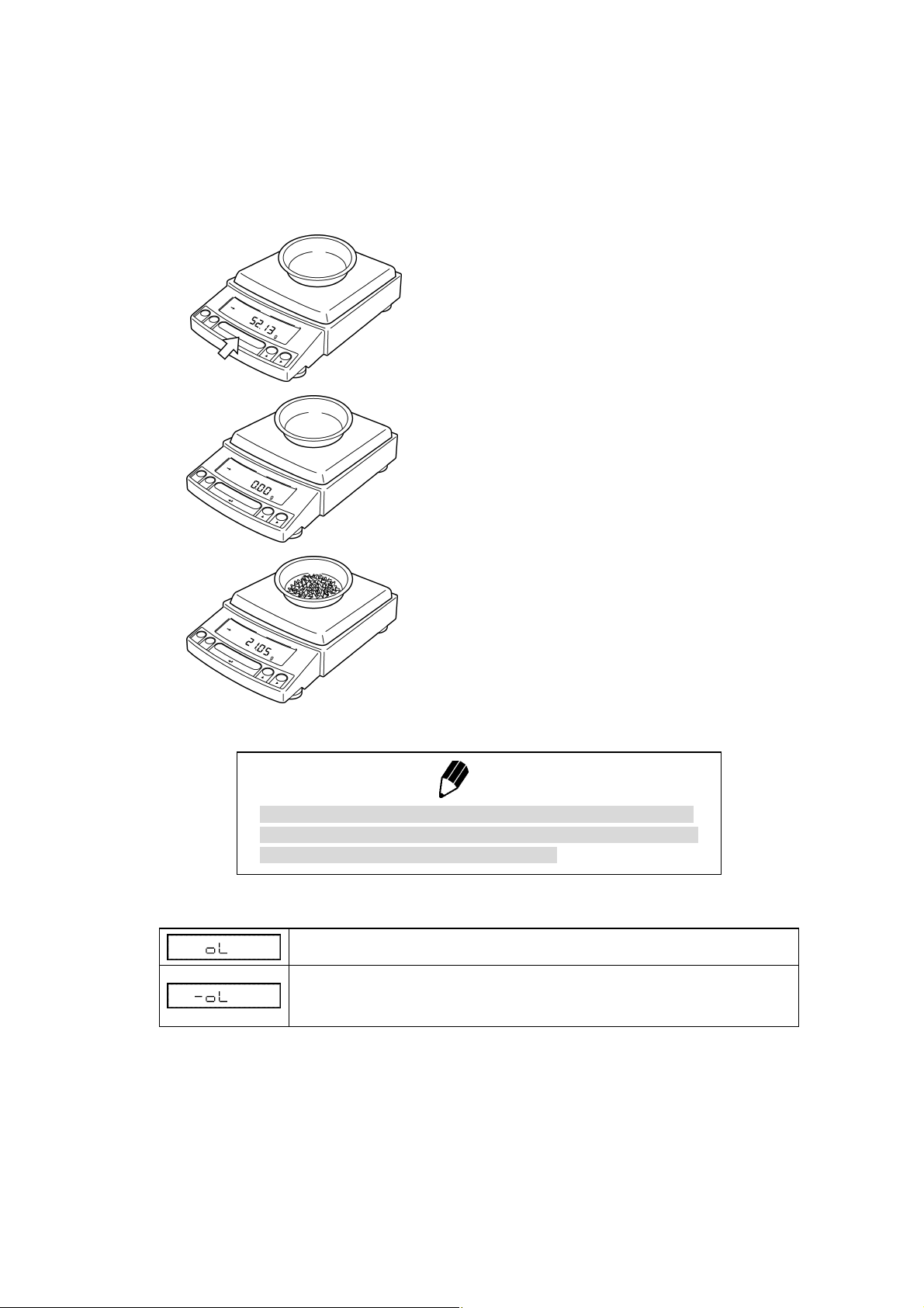
5.1 Weighing
1 If a weighing vessel (tare) is used, place it on the
pan and wait for the stability mark to illuminate.
2 Press the [O/T] key to zero the display. (This
operation is called “taring”.)
3 Place the object to be weighed on the pan.
Using a verified balance as a legal measuring instrument in the EU:
Indicates that the balance is set exactly to “Zero” with the zero-setting
function (+-0.25e: e = verification scale interval).
Error Displays During Weighing
Overload: Weighing capacity has been exceeded.
Negative Overload: The load on the balance is too light.
The pan is not adjusted properly.
4 Read the displayed value after the stability mark is
displayed.
Note
5 - 1
5.2 Changing the default Unit Display
Every time the [UNIT] key is pressed, the unit display changes sequentially among those set-up in 12.1
Unit Display Set-up. Gram, %, and PCS have been set-up as default units before delivery.
Notes
• Before a unit can be displayed it must be registered in 12.1 Unit Display Set-up.
• The registered units are displayed sequentially according to the order of the 12.1 Unit
Display Set-up.
Using a verified balance as a legal measuring instrument in the EU:
The balance must be used within the temperature range indicated on the verification
label.
When PSC (refer to 10.3.2), fully-automatic span calibration, is not activated, operator
must carry out span calibration with the built-in weight (refer to 4.5) upon blinking of the
Weight Symbol.
Note
5 - 2
6. WindowsDirect Function
6.1 Introduction: Experience it!
The Reflex HP series balance can transfer data directly to a personal computer running Lotus 1-2-3,
Excel, or other applications running on a Windows* operating system, as if the displayed value were
typed from the keyboard. This function is called WindowsDirect. Because this function directly accesses
the Windows operating system, communication software-installation troubles are eliminated. A cable
and a few simple settings are all that is needed to enable data transmission from the balance.
6.2 Set Up WindowsDirect
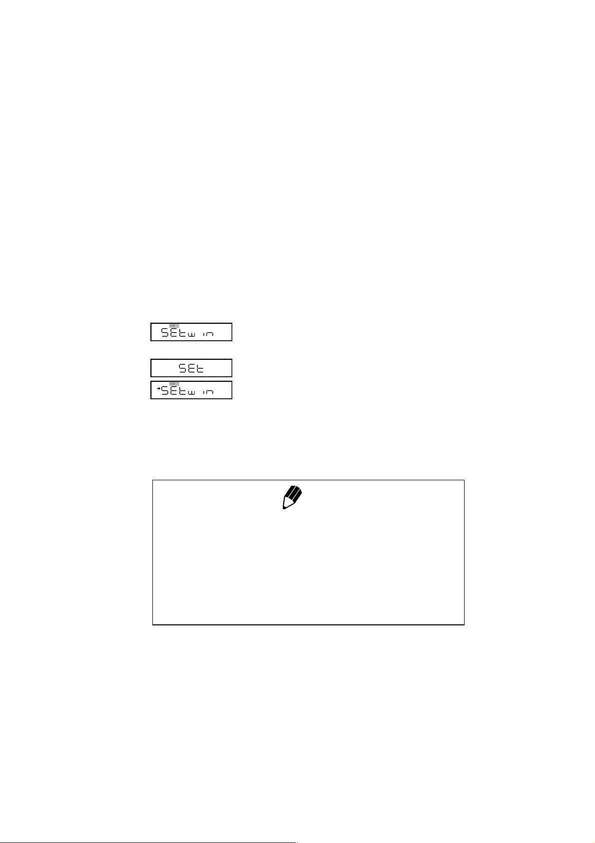
6.2.1 Setting Up the Balance
1 Press the [CAL] key twice from the gram-display.
“Setwin” appears.
2 Press the [O/T] key. Verify the stability mark is
illuminated with “Setwin” displayed. All the
communication settings for WindowsDirect have
been made.
3 Go to “STAND-BY” by pressing the [POWER] key
several times and unplug the AC adapter from the
balance. Unpluging the balance once is necessary
after the above setting.
Note
“Setwin” selects all the communication settings to enable
WindowsDirect function. However, the stability (arrow) mark at the
“Setwin” display is linked to the delimiter setting only. If any of the other
communication settings have been changed after the last set-up for
WindowsDirect, access the “Setwin” display and press [O/T] key to
cancel the stability mark once, then, repeat the setting up with “Setwin”
newly for WindowsDirect.
6 - 1
6.2.2 Cable Connection
6.2.3 Setting Up the Computer
(leave the balance unplugged)
1 Verify the balance display is “STAND-BY”.
2 Turn off the computer and disconnect the power
cord from the balance.
3 Connect the RS-232C cable to the balance.
4 Connect the RS-232C cable to the computer.
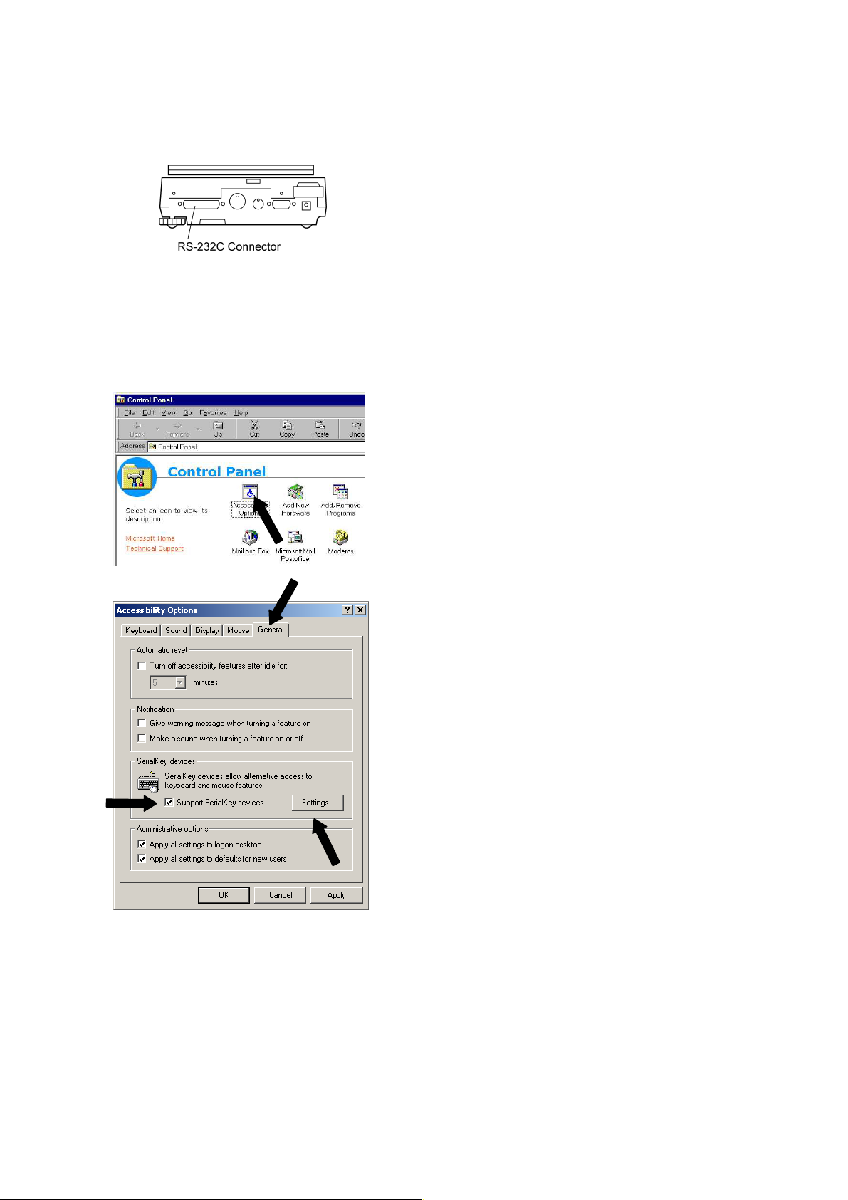
1 Turn ON the power to the computer and start
Windows*.
2 Click Start, choose Settings and Control Panel.
3 Select Accessibility Options.
4 Verify that there are no check marks for any items
on tabs including General.
5 Put a check mark at Support Serialkey device in
the General tab. This should be the only check
mark on all the tabs of Accessibility Options unless
Administrative options appears in the General
tab. Put check marks at both the items of
Administrative options to maintain the settings
even after restarting Windows.
6 Open Settings.
6 - 2
 Loading...