

Page 1
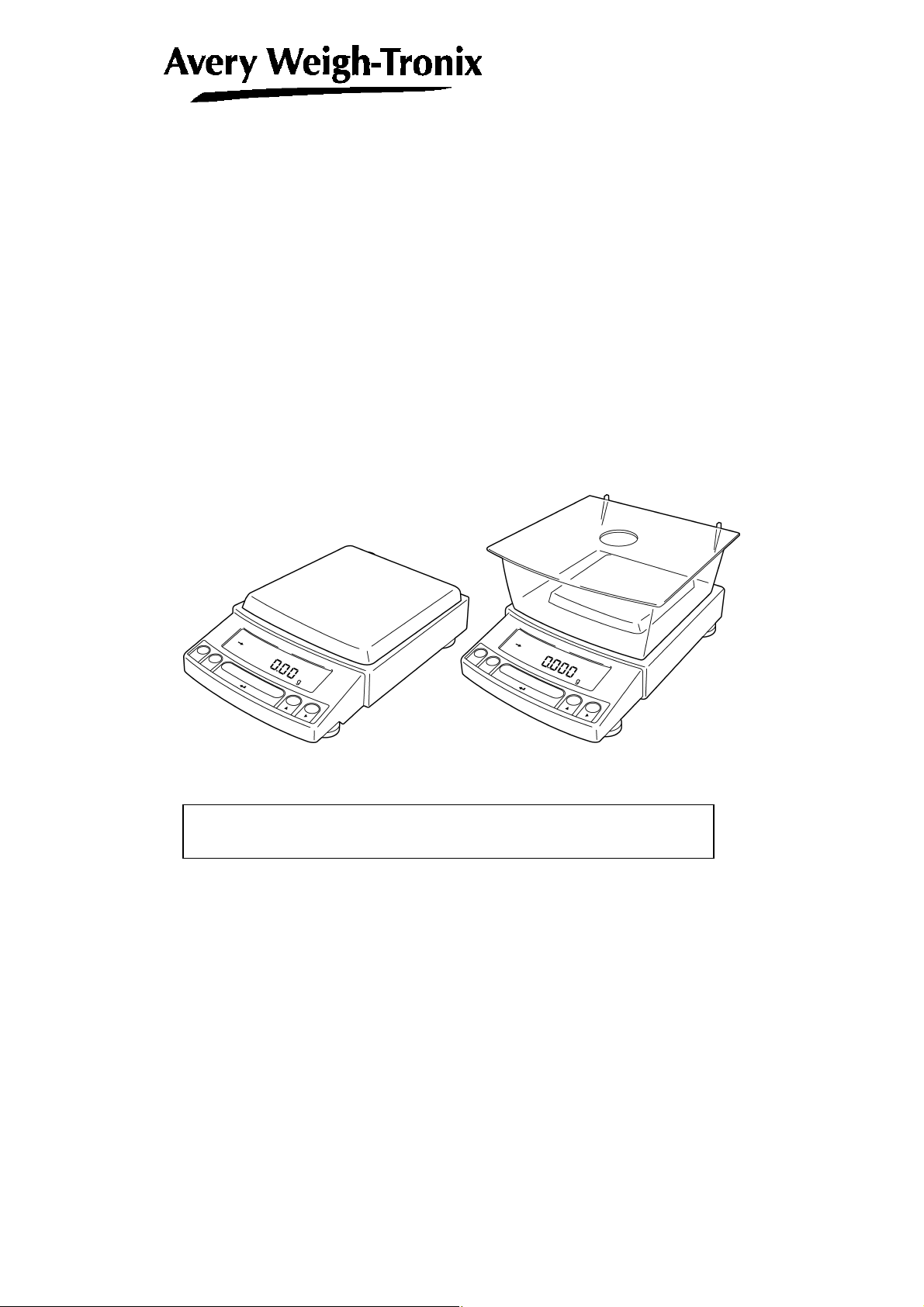
Electronic Balance
User Instructions
Reflex HP Series
Precision Balances
READ AND UNDERSTAND THIS MANUAL BEFORE OPERATION.
76103-918 Issue 1 16-03-2004
English
*76103-918*
Page 2
dNo.
Notation Conventions
Note
This instruction manual uses the following notation conventions to
indicate Safety Precautions and additional information.
Caution
Note
Indicates a potentially hazardous situation that may
result in injury to personnel or equipment damage.
Provides additional information needed to properly
use the balance.
Other conventions used in this manual include:
Item Description
1, 2, 3 .... Indicates the step number in a procedure or a sequence of changes in the balance display.
[ ] key Indicates the operation key on the balance. See 2.2.
mass display
NO.
Indicates that the balance is in the weighing mode and mass is displayed in one of the weighing
units.
These sections include information to make using the balance more convenient.
Indicates the menu item to be selected.
The number in the is the number of the menu item on the Menu Map. See 7.2 “ Menu Map”.
Notes on the use of verified balances as legal measuring instruments
Important notes about the use of verified balances as legal measuring
instruments in the EU are highlighted with the shadow.
Examples:
Using a verified balance as a legal measuring instrument in the EU:
Not applicable to a verified balance as a legal measuring
instrument in the EU:
There are special requirements on using a verified balance as a legal
measuring instrument in the EU. With the verified balances, some of
the functions are either unavailable or restricted.
"EU" includes the signatories of the European Economic Area
agreement.
- I -
Page 3
Safety Precautions
Caution
To ensure safe and proper operation of the balance, observe the
following precautions.
• Do not use the balance in hazardous areas.
This includes areas where the balance is exposed to dust or
flammable gases and liquids.
• Use the AC adapter specified by Avery Weigh-Tronix.
To prevent electric shock, never disassemble the AC adapter.
The AC adapter is designed for indoor use. Do not use the AC
adapter in exterior environments or where it may be splashed by
water.
Ensure that the power supply voltage meets the indicated range of
the AC adapter.
• Handle the balance carefully.
The balance is a precision instrument of solid design.
• Do not connect peripheral devices other than those
recommended by Avery Weigh-Tronix.
The balance may not operate properly if peripheral devices other
than those specified in this manual are used. The specifications of
the RS-232C/AUX connector are described in Section 7.6.1.
Connect the peripheral devices according to the methods described
in this instruction manual.
• Do not disassemble the balance, accessories, or peripheral unit.
- II -
Page 4
Declaration of Conformity
Manufacturer Avery Weigh-Tronix
Type REFLEX MODEL NOs
HPxxxCT
No. of EC type approval certificate T 6426
corresponds to the requirements of the following EC directives:
Non-Automatic Weighing
90/384/EEC1
Instruments
EMC Directive 89/336/EEC
Low Voltage Directive 73/23/EEC
The applicable harmonised
standards are:
EN60950, EN45501, EN55022,
EN55024, EN61000-3
Note 1 : This declaration is only valid if the non–automatic weighing
instrument was verified by the manufacturer or with a certificate
of conformity issued by a notified body.
A copy of the original signed declaration for this instrument is available
from:
Avery Weigh-Tronix, Foundry Lane, Smethwick, West Midlands B66 2LP England
- III -
Page 5
Declaration of Conformity
Manufacturer Avery Weigh-Tronix
Type REFLEX MODEL NOs
HPxxx/HPxxxC
corresponds to the requirements of the following EC directives:
EMC Directive 89/336/EEC
Low Voltage Directive 73/23/EEC
The applicable harmonised
standards are:
EN60950, EN45501, EN55022,
EN55024, EN61000-3
A copy of the original signed declaration for this instrument is available
from:
Avery Weigh-Tronix, Foundry Lane, Smethwick, West Midlands B66 2LP England
- IV -
Page 6

Avery Weigh-Tronix Balances and 21 CFR Part 11
21 CFR Part 11
21 CFR Part 11, Electronic Records, Electronic Signatures, Final Rule (often referred to as Part 11)
is the United States Food and Drug Administration (FDA) regulation affecting computer resources
and electronic records that are used for any document that is required to be kept and maintained by
FDA regulations.
Requirements concerning computer resources security are key elements in Part 11.
The controls implemented as a result of security related requirements are intended to result in
trusted records.
Avery Weigh-Tronix CLASS-Balance Agent
Avery Weigh-Tronix provides a means for compliance with 21 CFR Part 11 with Avery Weigh-Tronix
CLASS-Balance Agent software, part of a comprehensive laboratory data management system,
Avery Weigh-Tronix CLASS Agent.
Ask your Avery Weigh-Tronix representative about it.
Avery Weigh-Tronix WindowsDirect
When Avery Weigh-Tronix balances are integrated with laboratory software by means of our
WindowsDirect function, no communication software is required or used.
The Avery Weigh-Tronix balance functions as a primary device in the system, just as a keyboard,
mouse or other data entry hardware does.
For this reason, system validation and compliance may be greatly simplified with the use of Avery
Weigh-Tronix balances.
Two-way Communication
Avery Weigh-Tronix balances have always been computer friendly and they can be set up for
bi-directional communication as part of a fully automated production system or LIMS.
This manual includes the command codes and information needed by programmers to integrate
Avery Weigh-Tronix balances with their software.
- V -
Page 7

Notation Conventions
Safety Precautions
Declaration Of Conformity
Contents
1. Introduction
・・・・・・・・・・・・・・・・・・・・・・・・・・・・・・・・・・・・・・・・・・・・・・・・・・・・・・
2. Components, Names and Functions
2.1 Components
2.2 Key Panel and Operation
2.3 Balance Display and Functions
・・・・・・・・・・・・・・・・・・・・・・・・・・・・・・・・・・・・・・・・・・・・・・・・・・・・・・・・・・・・・・・・
・・・・・・・・・・・・・・・・・・・・・・・・・・・・・・・・・・・・・・・・・・・・・・・・・・・・・
・・・・・・・・・・・・・・・・・・・・・・・・・・・・・・・・・・・・・・・・・・・・・・・・
・・・・・・・・・・・・・・・・・・・・・・・・・・・・・・・・
3. Specifications
・・・・・・・・・・・・・・・・・・・・・・・・・・・・・・・・・・・・・・・・・・・・・・・・・・・・
4. Installation
4.1 Choosing the Installation Site
4.2 Unpacking and Delivery Inspection
4.3 Installation
4.4 Turning On the Power
4.5 Span Calibration
・・・・・・・・・・・・・・・・・・・・・・・・・・・・・・・・・・・・・・・・・・・・・・・・・・・・・・・
・・・・・・・・・・・・・・・・・・・・・・・・・・・・・・・・・・・・・・・・・・・・・・・・・
・・・・・・・・・・・・・・・・・・・・・・・・・・・・・・・・・・・・・・・・・・・・・
・・・・・・・・・・・・・・・・・・・・・・・・・・・・・・・・・・・・・・・・・・・・・・・・・・・・・・・・・・・・・・・・・・
・・・・・・・・・・・・・・・・・・・・・・・・・・・・・・・・・・・・・・・・・・・・・・・・・・・・・・・・
・・・・・・・・・・・・・・・・・・・・・・・・・・・・・・・・・・・・・・・・・・・・・・・・・・・・・・・・・・・・・
5. Basic Operation ---Read up to this chapter for basic but correct weighing
5.1 Weighing
5.2 Changing the default Unit Display
6. WindowsDirect Function
6.1 Introduction: Experience it!
6.2 Set Up WindowsDirect
6.2.1 Setting Up the Balance
6.2.2 Cable Connection
6.2.3 Setting Up the Computer
6.2.4 Start and Checking Operation
6.3 Troubleshooting
6.4 Notes on WindowsDirect
7. Menu Item Selection
7.1 What is the Menu?
7.2 Menu Map
・・・・・・・・・・・・・・・・・・・・・・・・・・・・・・・・・・・・・・・・・・・・・・・・・・・・・・・・・・・・・・・・・・・
・・・・・・・・・・・・・・・・・・・・・・・・・・・・・・・・・・・・・・・・・・・・・・
・・・・・・・・・・・・・・・・・・・・・・・・・・・・・・・・・・・・・・・・・・
・・・・・・・・・・・・・・・・・・・・・・・・・・・・・・・・・・・・・・・・・・・・・・・・・・・・
・・・・・・・・・・・・・・・・・・・・・・・・・・・・・・・・・・・・・・・・・・・・・・・・・・・・・・・
・・・・・・・・・・・・・・・・・・・・・・・・・・・・・・・・・・・・・・・・・・・・・・・・
・・・・・・・・・・・・・・・・・・・・・・・・・・・・・・・・・・・・・・・・・・・・・・・・・・・・
・・・・・・・・・・・・・・・・・・・・・・・・・・・・・・・・・・・・・・・・・・・・・・
・・・・・・・・・・・・・・・・・・・・・・・・・・・・・・・・・・・・・・・・・・
・・・・・・・・・・・・・・・・・・・・・・・・・・・・・・・・・・・・・・・・・・・・・・・・・・・・・・・・・・・・・
・・・・・・・・・・・・・・・・・・・・・・・・・・・・・・・・・・・・・・・・・・・・・・・・・・・・・
・・・・・・・・・・・・・・・・・・・・・・・・・・・・・・・・・・・・・・・・・・・・・・
・・・・・・・・・・・・・・・・・・・・・・・・・・・・・・・・・・・・・・・・・・・・・・・・・・・・・・・・・・・
・・・・・・・・・・・・・・・・・・・・・・・・・・・・・・・・・・・・・・・・・・・・・・・・・・・・・・・・・・・・・・・・・・
- i -
・・・・・・・・・
1-1
2-1
2-1
2-2
2-3
3-1
4-1
4-1
4-3
4-4
4-7
4-8
5-1
5-1
5-2
6-1
6-1
6-1
6-1
6-2
6-2
6-4
6-5
6-7
7-1
7-1
7-1
Page 8

7.3 Menu Item Selection Procedure
7.4 Setting Numeric Values
7.5 Related Useful Functions
7.5.1 Last Menu Recall
7.5.2 Returning to the Default Settings (menu reset)
7.5.3 Menu Lock
7.6 Navigating the Menu Map
7.6.1 Specifications of the RS-232C Connector
7.6.2 Table of Unit Conversion Information
・・・・・・・・・・・・・・・・・・・・・・・・・・・・・・・・・・・・・・・・・・・・・・・・・・・・・・
・・・・・・・・・・・・・・・・・・・・・・・・・・・・・・・・・・・・・・・・・・・・・・・・・・・・・・・・・・
・・・・・・・・・・・・・・・・・・・・・・・・・・・・・・・・・・・・・・・・・・・・・・・
・・・・・・・・・・・・・・・・・・・・・・・・・・・・・・・・・・・・・・・・・・・・・・・・・・・・・
・・・・・・・・・・・・・・・・・・・・・・・・・・・・・・・・・・・・・・・・・・・・・・・・・・・・・
・・・・・・・・・・・・・・・・・・・・・・・・・・・・・・・・・・・・・・・・・・・・・・・・・・・・・
8. Built-in Clock Set-up
8.1 Date
8.2 Time
8.3 Setting Display During Stand-by
・・・・・・・・・・・・・・・・・・・・・・・・・・・・・・・・・・・・・・・・・・・・・・・・・・・・・・・・・・・・・・・・・・・・・・・
・・・・・・・・・・・・・・・・・・・・・・・・・・・・・・・・・・・・・・・・・・・・・・・・・・・・・・・・・・・・・・・・・・・・・・・
・・・・・・・・・・・・・・・・・・・・・・・・・・・・・・・・・・・・・・・・・・・・・・
・・・・・・・・・・・・・・・・・・・・・・・・・・・・・・・・・・・・・・・・・・・・・・・
9. Display Settings
9.1 Bar graph display
9.2 Changing the Minimum Display Digit (10d:1d)*
・・・・・・・・・・・・・・・・・・・・・・・・・・・・・・・・・・・・・・・・・・・・・・・・・・
・・・・・・・・・・・・・・・・・・・・・・・・・・・・・・・・・・・・・・・・・・・・・・・・・・・・・・・・・・・・
10. Calibration
10.1 What is calibration?
10.2 Calibration Execution
10.2.1 Span Calibration Using the Built-in Weight (HPxxxC Series Only)
10.2.2 Calibration Check Using the Built-in Weight (HPxxxC Series Only)*
10.2.3 Span Calibration Using External Weights*
10.2.4 Calibration Check Using External Weights*
10.3 Calibration Setting
10.3.1 Selecting the Calibration Type*
10.3.2 PSC Fully-automatic Calibration (HPxxxC series only)
10.3.3 Clock-CAL Fully-automatic Calibration (HPxxxC series only)
10.3.4 PCAL: Calibration of the Built-in Weight (HPxxxC series only)*
10.3.5 PCAL Password Setting (HPxxxC series only)*
10.4 For GLP/GMP/ISO Conformance
10.4.1 Calibration Report Setting
10.4.2 Balance ID Setting
・・・・・・・・・・・・・・・・・・・・・・・・・・・・・・・・・・・・・・・・・・・・・・・・・・・・・・・
・・・・・・・・・・・・・・・・・・・・・・・・・・・・・・・・・・・・・・・・・・・・・・・・・・・・・・・・・・
・・・・・・・・・・・・・・・・・・・・・・・・・・・・・・・・・・・・・・・・・・・・・・・・・・・・・・・・
・・・・・・・・・・・・・・・・・・・・・・・・・・・・・・・・・・・・・・・・・・・・・・・・・・・・・・・・・・・
・・・・・・・・・・・・・・・・・・・・・・・・・・・・・・・・・・・・・・・・・・・・・・
・・・・・・・・・・・・・・・・・・・・・・・・・・・・・・・・・・・・・・・・・・・・・
・・・・・・・・・・・・・・・・・・・・・・・・・・・・・・・・・・・・・・・・・・・・・・・・・・・
11. Environment
11.1 Overview
11.2 Stability and Response (Averaging)
11.3 Stability Detection Band
・・・・・・・・・・・・・・・・・・・・・・・・・・・・・・・・・・・・・・・・・・・・・・・・・・・・・
・・・・・・・・・・・・・・・・・・・・・・・・・・・・・・・・・・・・・・・・・・・・・・・・・・・・・・・・・・・・・・・・・・・
・・・・・・・・・・・・・・・・・・・・・・・・・・・・・・・・・・・・・・・・・・・・
・・・・・・・・・・・・・・・・・・・・・・・・・・・・・・・・・・・・・・・・・・・・・・・・・・・・・・
・・・・・・・・・・・・・・・・・・・・・・・・・・・
・・・・・・・・・・・・・・・・・・・・・・・・・・・・・・・
・・・・・・・・・・・・・・・・・・・・・・・・・・・・・・・・・・・
・・・・・・・・・・・・・・・・・・・・・・・・・・・・・・・・・・
・・・・・・・・・・・
・・・・・・・・・
・・・・・・・・・・・・・・・・・・・・・・・・・・・・・・・
・・・・・・・・・・・・・・・・・・・・・・・・・・・・・・
・・・・・・・・・・・・・・・・・・・・・・・・・・・・・・・・・・・・・・・・・
・・・・・・・・・・・・・・・・・・・・
・・・・・・・・・・・・・・・
・・・・・・・・・・・・・
・・・・・・・・・・・・・・・・・・・・・・・・・・・
7-2
7-4
7-5
7-5
7-5
7-6
7-7
7-12
7-13
8-1
8-1
8-1
8-2
9-1
9-1
9-1
10-1
10-1
10-2
10-2
10-3
10-4
10-5
10-6
10-6
10-6
10-7
10-8
10-9
10-10
10-10
10-10
11-1
11-1
11-1
11-2
- ii -
Page 9

11.4 Tracking
・・・・・・・・・・・・・・・・・・・・・・・・・・・・・・・・・・・・・・・・・・・・・・・・・・・・・・・・・・・・・・・・・・・・
12. Units
12.1 Unit Display Set-up
12.2 Percentage (%) Conversion
・・・・・・・・・・・・・・・・・・・・・・・・・・・・・・・・・・・・・・・・・・・・・・・・・・・・・・・・・・・・
・・・・・・・・・・・・・・・・・・・・・・・・・・・・・・・・・・・・・・・・・・・・・・・・・・・・・・・・・・
・・・・・・・・・・・・・・・・・・・・・・・・・・・・・・・・・・・・・・・・・・・・・・・・・・・
13. Enhancing Productivity
13.1 Checkweighing and Target Display
13.1.1 Checkweighing (Comparator) Display Type 1
13.1.2 Checkweighing (Comparator) Display Type 2
13.1.3 Target Mode
13.2 Piece Counting (PCS)
13.3 Auto Print
13.4 Auto Zero*
13.5 Zero Range
13.6 Taring/Printing at Stability*
13.7 Pretaring Value*
・・・・・・・・・・・・・・・・・・・・・・・・・・・・・・・・・・・・・・・・・・・・・・・・・・・・・・・・・・・・・・・・・・・
・・・・・・・・・・・・・・・・・・・・・・・・・・・・・・・・・・・・・・・・・・・・・・・・・・・・・・・・・・・・・・・・・・
・・・・・・・・・・・・・・・・・・・・・・・・・・・・・・・・・・・・・・・・・・・・・・・・・・・・・・・・・・・・・・・・・
・・・・・・・・・・・・・・・・・・・・・・・・・・・・・・・・・・・・・・・・・・・・・・・・・・・・・・・・・・・・・
14. Application Functions
14.1 Solid Specific Gravity Measurement
14.2 Liquid Density Measurement
14.3 Peak Hold*
14.4 Interval Timer*
14.5 Auto-Memory and Zeroing*
14.6 Animal Weighing*
・・・・・・・・・・・・・・・・・・・・・・・・・・・・・・・・・・・・・・・・・・・・・・・・・・・・・・・・・・・・・・・・・
・・・・・・・・・・・・・・・・・・・・・・・・・・・・・・・・・・・・・・・・・・・・・・・・・・・・・・・・・・・・・・
・・・・・・・・・・・・・・・・・・・・・・・・・・・・・・・・・・・・・・・・・・・・・・・・・・・・・・・・・・・・
・・・・・・・・・・・・・・・・・・・・・・・・・・・・・・・・・・・・・・・・・・・
・・・・・・・・・・・・・・・・・・・・・・・・・・・・・・・・・・・・・・・・・・・・
・・・・・・・・・・・・・・・・・・・・・・・・・・・・・・・・・・・・・・・・・・・・・・・・・・・・・・・・・
・・・・・・・・・・・・・・・・・・・・・・・・・・・・・・・・・・・・・・・・・・・・・・・・・・・・・・・・
・・・・・・・・・・・・・・・・・・・・・・・・・・・・・・・・・・・・・・・・・・・・・・・・・・・・
・・・・・・・・・・・・・・・・・・・・・・・・・・・・・・・・・・・・・・・・・・・・・
・・・・・・・・・・・・・・・・・・・・・・・・・・・・・・・・・・・・・・・・・・・・
・・・・・・・・・・・・・・・・・・・・・・・・・・・・・・・・・・・・・・・・・・・・・・・・・・
・・・・・・・・・・・・・・・・・・・・・・・・・・・・・・・・・・・・・・・・・・・・・・・・・・・
15. Connecting Peripheral Instruments
15.1 Electronic Printer
15.2 Personal Computer - RS-232C -
15.2.1 Connecting the Cable
15.2.2 Data Format
15.2.3 Using Command Codes
15.2.4 Multi-Connection Mode
15.3 Communication Setting
15.3.1 Overview
15.3.2 Handshaking
15.3.3 Format
15.3.4 Communication Speed
15.3.5 Parity / Bit Length
15.3.6 Stop Bit
15.3.7 Delimiter
・・・・・・・・・・・・・・・・・・・・・・・・・・・・・・・・・・・・・・・・・・・・・・・・・・・・・・・・・・・・
・・・・・・・・・・・・・・・・・・・・・・・・・・・・・・・・・・・・・・・・・・・・・・・
・・・・・・・・・・・・・・・・・・・・・・・・・・・・・・・・・・・・・・・・・・・・・・・・・
・・・・・・・・・・・・・・・・・・・・・・・・・・・・・・・・・・・・・・・・・・・・・・・・・・・・・・・・・
・・・・・・・・・・・・・・・・・・・・・・・・・・・・・・・・・・・・・・・・・・・・・・・
・・・・・・・・・・・・・・・・・・・・・・・・・・・・・・・・・・・・・・・・・・・・・・・
・・・・・・・・・・・・・・・・・・・・・・・・・・・・・・・・・・・・・・・・・・・・・・・・・・・・・・・
・・・・・・・・・・・・・・・・・・・・・・・・・・・・・・・・・・・・・・・・・・・・・・・・・・・・・・・・・・・・
・・・・・・・・・・・・・・・・・・・・・・・・・・・・・・・・・・・・・・・・・・・・・・・・・・・・・・・・
・・・・・・・・・・・・・・・・・・・・・・・・・・・・・・・・・・・・・・・・・・・・・・・・・・・・・・・・・・・・・・
・・・・・・・・・・・・・・・・・・・・・・・・・・・・・・・・・・・・・・・・・・・・・・・・
・・・・・・・・・・・・・・・・・・・・・・・・・・・・・・・・・・・・・・・・・・・・・・・・・・・・
・・・・・・・・・・・・・・・・・・・・・・・・・・・・・・・・・・・・・・・・・・・・・・・・・・・・・・・・・・・・・
・・・・・・・・・・・・・・・・・・・・・・・・・・・・・・・・・・・・・・・・・・・・・・・・・・・・・・・・・・・・
・・・・・・・・・・・・・・・・・・・・・・・・・・・・
・・・・・・・・・・・・・・・・・・・・・・・・・・・・
・・・・・・・・・・・・・・・・・・・・・・・・・・・・・・・・
11-2
12-1
12-1
12-2
13-1
13-1
13-2
13-2
13-3
13-4
13-5
13-6
13-6
13-7
13-8
14-1
14-1
14-3
14-5
14-6
14-7
14-8
15-1
15-1
15-2
15-2
15-3
15-4
15-9
15-12
15-12
15-12
15-13
15-13
15-13
15-13
15-14
- iii -
Page 10

16. Maintenance and Transportation
16.1 Maintenance
16.2 Moving the Balance
17. Troubleshooting
17.1 General Display
17.2 Error Display
17.3 Troubleshooting
17.4 LCD (Liquid Crystal Display) Check
・・・・・・・・・・・・・・・・・・・・・・・・・・・・・・・・・・・・・・・・・・・・・・・・・・・・・・・・・・・・・・・・
・・・・・・・・・・・・・・・・・・・・・・・・・・・・・・・・・・・・・・・・・・・・・・・・・・・・・・・・・・
・・・・・・・・・・・・・・・・・・・・・・・・・・・・・・・・・・・・・・・・・・・・・・・・・・
・・・・・・・・・・・・・・・・・・・・・・・・・・・・・・・・・・・・・・・・・・・・・・・・・・・・・・・・・・・・・
・・・・・・・・・・・・・・・・・・・・・・・・・・・・・・・・・・・・・・・・・・・・・・・・・・・・・・・・・・・・・・・・
・・・・・・・・・・・・・・・・・・・・・・・・・・・・・・・・・・・・・・・・・・・・・・・・・・・・・・・・・・・・・
・・・・・・・・・・・・・・・・・・・・・・・・・・・・・・・・・・・
・・・・・・・・・・・・・・・・・・・・・・・・・・・・・・・・・・・・・・・・・・・・
16-1
16-1
16-1
17-1
17-1
17-2
17-3
17-3
- iv -
Page 11

1. Introduction
The Avery Weigh-Tronix Reflex HP series of precision balances give you high performance, fast
response, and durability. Features available include multiple units of measure, piece counting,
checkweighing functions, auto print, and GLP/GMP/ISO output including date and time data from a
built-in clock.
The Reflex HP series also features Avery Weigh-Tronix’s WindowsDirect communication, which
requires no software installation to quickly integrate balances with laboratory or business software. This
function eliminates data input errors and offers extensive flexibility for application development without
compromising compliance or data security.
The Reflex HP series balance incorporates a motor-driven built-in calibration weight that can
automatically calibrate sensitivity without the use of external weights.
Read this manual carefully before using this instrument and keep it with the balance for future reference.
This manual refers to the different types of Reflex HP series balance as follows:
HPxxx
HPxxxC
HPxxxCT
Where: xxx indicates capacity of balance (g)
C indicates built in calibration
T indicates EC Type Approval
The type of balance is classified as “large pan” or “small pan” depending on the size of the pan.
Large pan type: Balance model with a capacity of 2200g or more.
Small pan type: Balance model with a capacity of 820g or less.
1 - 1
Page 12

© Avery Berkel Limited 2004. All rights reserved.
The information contained herein is the property of Avery Berkel Limited and is supplied without liability
for errors or omissions. No part may be reproduced or used except as authorised by contract or other
written permission. The copyright and the foregoing restriction on reproduction and use extend to all
media in which the information may be embodied.
Trademarks and acknowledgements
Avery, Avery Berkel, Avery Weigh-Tronix are registered trademarks in certain jurisdictions and owned
and registered by companies within the Avery Weigh-Tronix Group.
All brands and product names used within this document are trademarks or registered trademarks of
their respective holders.
IMPORTANT
When programming or configuring the equipment you must ensure that you comply with all relevant
standards and legislation. The example settings given in this book may not be legal for trade with the
public.
1 - 2
Page 13
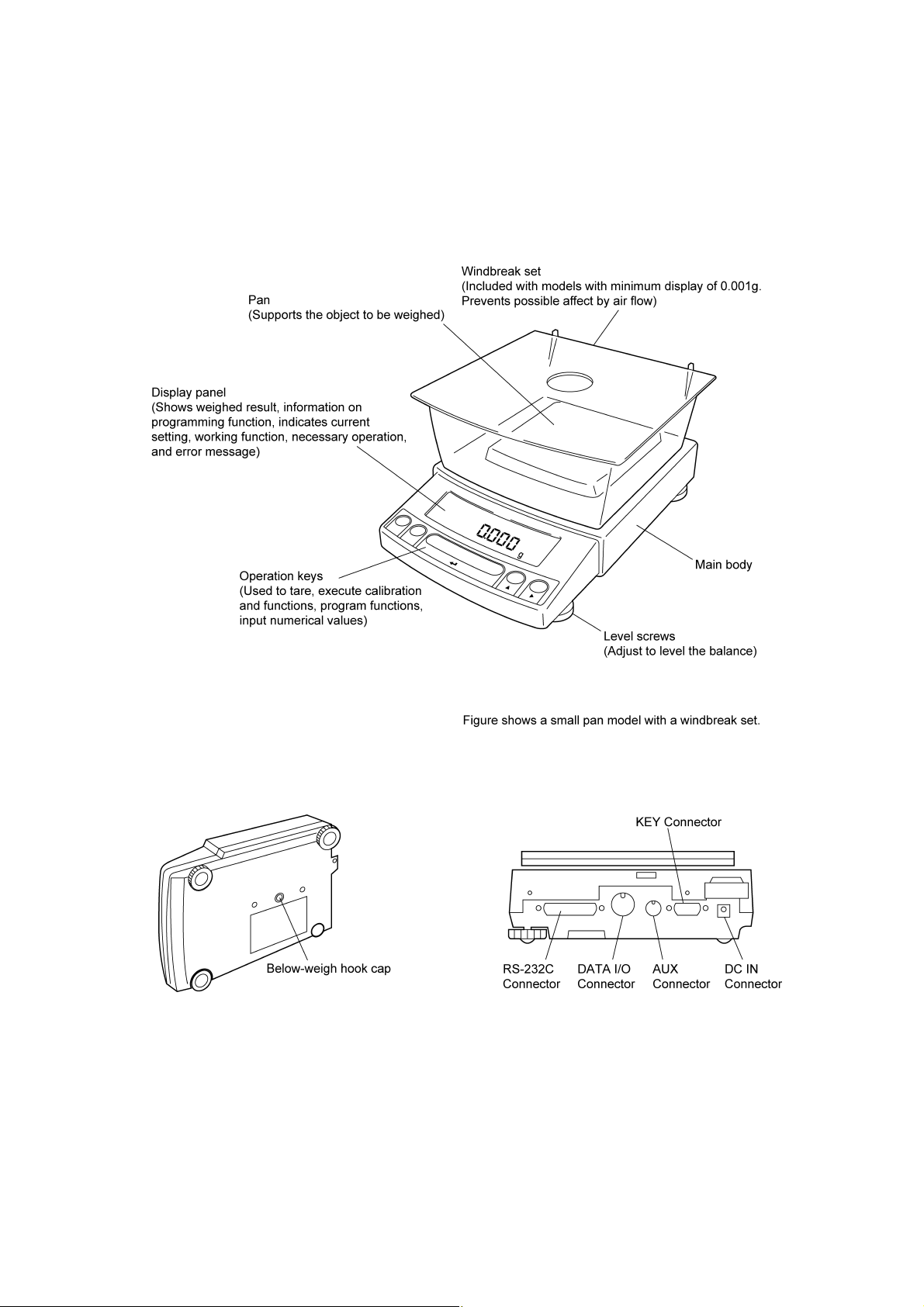
2. Components, Names & Functions
2.1 Components
2 - 1
(Connectors on the back)
Page 14
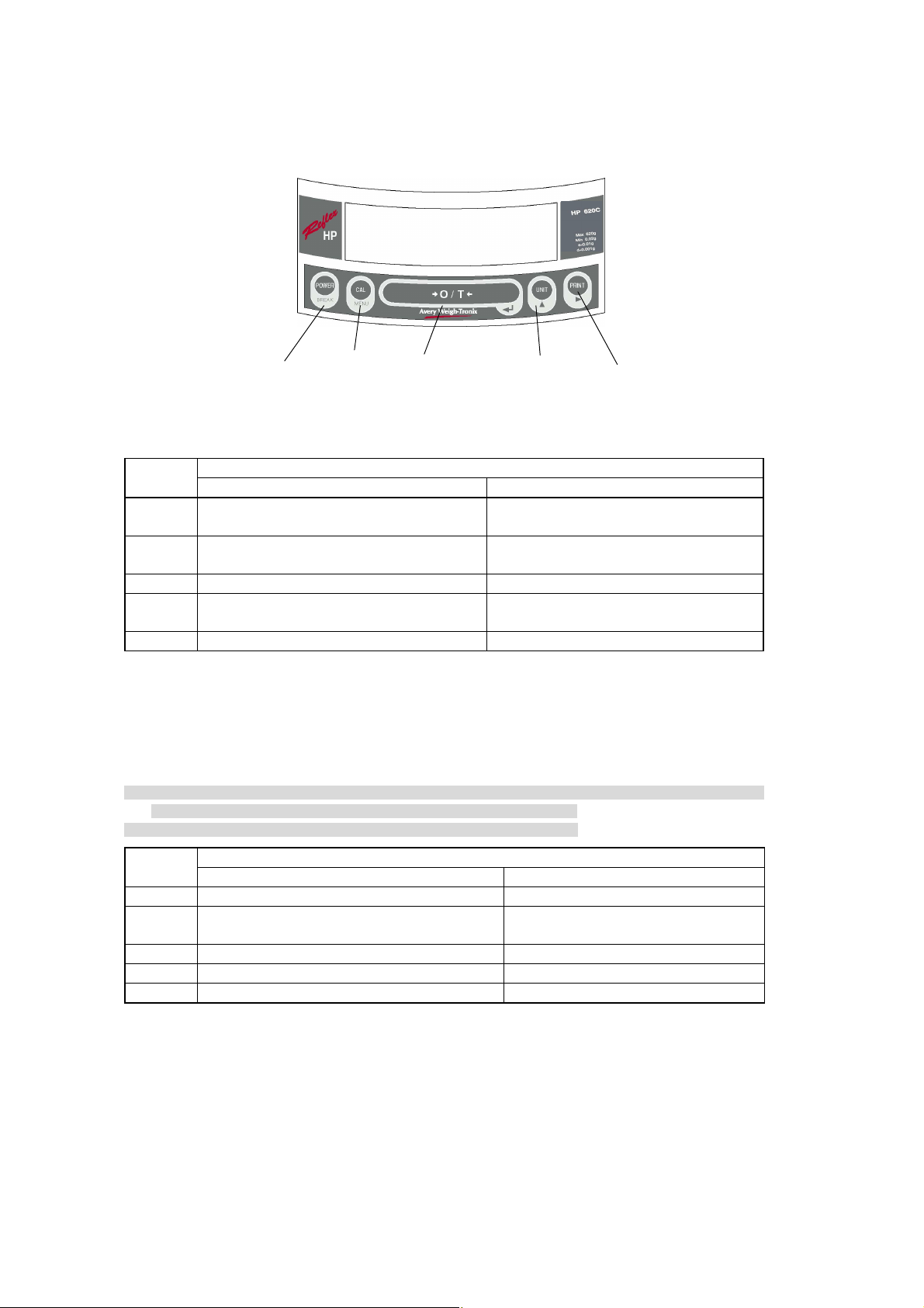
2.2 Key Panel and Operation
[POWER] key [CAL] key [O/T] key [UNIT] key [PRINT] key
Function of the keys
Key
[POWER]
[CAL]
[O/T] Tares the balance. (Displays zero.) (*2)(*5) Displays the Pretare value.(*6)
[UNIT]
[PRINT] Sends the displayed value to a peripheral device. Sends the date and time to a peripheral device.
*1 This key is used to set values when percent (%), number (PCS), solid specific gravity (▼d), or liquid specific
gravity (d) are displayed.
*2 When a Pretare value is set, zero is not displayed and [- Pretare value] is displayed.(*6)
*3 Units other than “g” must be set up before they can be used for measurement. Only gram (g), percent (%), and
piece counting (PCS) are set-up before shipment. To set up other units or specific gravity measurement, refer to
section 12., or 14.1, 14.2.
*4 When the unit is set to 10d, the resolution of the minimum display is decreased by one decimal place.
*5 Either "Taring" (at a weight exceeding 2.5% of the capacity) or "Zeroing" (at a weight within 2.5% of the capacity)
takes place with a verified balance as a legal measuring instrument in the EU.
*6 Not applicable to a verified balance as a legal measuring instrument in the EU.
Key
[POWER] Returns to the previous menu level Returns to the mass display.
[CAL] Moves to the next menu item.
[O/T] Selects and sets the currently displayed menu item. No operation.
[UNIT] Increases the numeric value of the blinking digit by 1. No operation.
[PRINT] Moves to the next digit during numeric value entry. No operation.
Switches between the operation and standby
modes.
Enters span calibration or menu item selection.
(*1)
Changes the weighing unit or selects specific
gravity measurement. (*3)
Press Once and Release Press and Hold for About 3 Seconds
Press Once and Release Press and Hold for About 3 Seconds
During Weighing
Exits the application function and returns to the
mass display.
Displays the last menu item that was set.
(Last menu recall)
Switches between the 1d and 10d display. (*4)
(*6)
During Menu Item Selection
Displays the last menu item that was set.
(Last Menu Recall)
2 - 2
Page 15
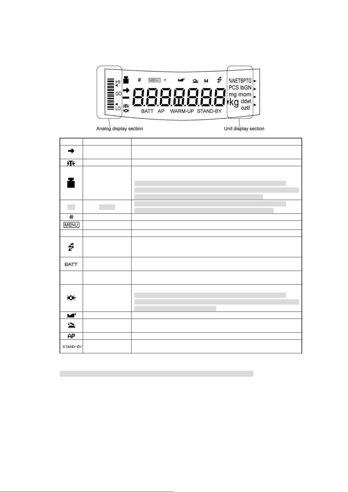
2.3 Balance Display and Functions
Display Name Description
Stability mark
[ ] Bracket
Number symbol Indicates numeric value entry.
* Asterisk Indicates that the displayed numeric value is not a mass value.
▼ inverse triangle symbol
Zero symbol
Animal symbol Indicates the set-up of Animal Weighing function.(*2)
Auto Print symbol Indicates the set-up of Auto Print function.
*1 Stability symbol
The displayed value may change while the stability symbol remains illuminated if the load is changing slowly or if
the stability detection band has been set to a large value.
Tare symbol Indicates that a Pretare value has been set.(*2)
Weight symbol
Menu symbol Indicates that the menu lock is on. Illuminates during menu item selection.
Communication
symbol
Battery symbol
Auto-Memory &
Zeroing symbol
Stand-by symbol
Indicates that the weighed value is stable. (*1) In menu item selection, indicates
currently selected item.
Illuminates during span calibration. In menu selection, indicates setting related
to calibration. Blinks before automatic span calibration starts.
Note: Using a verified balance as a legal measuring instrument in the EU:
When automatic span calibration is not activated, operator must carry out span
calibration with the built-in weight upon blinking of this symbol.
Note: Using a verified balance as a legal measuring instrument in the EU:
The figure bordered by the bracket is the auxiliary indicating device.
Illuminates during communication to external equipment through the RS-232C
or DATA I/O connector. In menu selection, indicates setting related to
communication.
When the balance is operated with the optional battery pack, this symbol
illuminates to indicate that the battery voltage has dropped.
Indicates the set-up of solid specific gravity measurement. Used as a substitute
for the decimal point.
Indicates the set-up of Auto Zero function.(*2)
Note: Using a verified balance as a legal measuring instrument in the EU:
Indicates that the balance is set exactly to "Zero" with the zero-setting function
(+-0.25e: e = verification scale interval).
Indicates the set-up of Auto-Memory and Zeroing.(*2)
Illuminates when the balance power is in the standby mode.
Also illuminates when the application function has entered the standby mode.
*2 Not applicable to a verified balance as a legal measuring instrument in the EU
2 - 3
Page 16
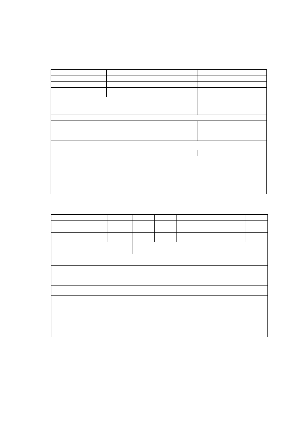
3. Specifications
Reflex HP Series with internal Calibration
HP Series Model HP420C HP620C HP2200C HP4200C HP6200C HP820C HP4200SC HP8200C
Capacity 420g 620g 2200g 4200g 6200g 820g 4200g 8200g
Minimum display 0.001g 0.001g 0.01g 0.01g 0.01g 0.01g 0.1g 0.1g
Calibration range
with external weights
Repeatability (σ) ≤0.001g ≤0.01g ≤0.008g ≤0.08g
Linearity ±0.002g ±0.02g ±0.01g ±0.1g
Response time (s) 1.5 - 2.5 0.7 - 1.2
Ambient temperature (°C)
Temperature coefficient
of sensitivity (ppm/°C)
(10 - 30°C)
Pan size (mm) approx.
Main body dimensions
(mm) approx.
Weight (kg) approx. 3.4 4.6 3.4 4.6
Display LCD with backlight
Power requirement 12V 1A
Data I/O RS-232C
100 - 420g 100 - 620g 1000 - 2200g 1000 - 4200g 1000 - 6200g 100 - 820g 1000 - 4200g 1000 - 8200g
5 - 40
±3 ±5
108×105 170×180 108×105 170 X 180
190W×317D×78H
Features
WindowsDirect, Clock-CAL, GLP/GMP/ISO conformance, Analog display, % display, PCS, User unit, Animal weighing,
Specific gravity measurement S/W, Checkweighing
Reflex HP Series with external Calibration
HP Series Model HP420 HP620 HP2200 HP4200 HP6200 HP820 HP4200S HP8200
Capacity 420g 620g 2200g 4200g 6200g 820g 4200g 8200g
Minimum display 0.001g 0.001g 0.01g 0.01g 0.01g 0.01g 0.1g 0.1g
Calibration range
with external weights
Repeatability (σ) ≤ 0.001g ≤0.01g ≤0.008g ≤0.08g
Linearity ± 0.002g ±0.02g ±0.01g ±0.1g
Response time (s) 1.5 - 2.5 0.7 - 1.2
Ambient temperature (°C)
Temperature coefficient
of sensitivity (ppm/°C)
(10 - 30°C)
Pan size (mm) approx. 108 × 105 170 × 180 108×105 170×180
Main body dimensions
(mm) approx.
Weight (kg) approx. 2.7 2.9 2.7 2.9
Display LCD with backlight
Power requirement 12V 1A
Data I/O RS-232C
Features
100 - 420g 100 - 620g 1000 - 2200g 1000 - 4200g 1000 - 6200g 100 - 820g 1000 - 4200g 1000 - 8200g
5 - 40
±3 ±5
190W × 317D × 78H
WindowsDirect, GLP/GMP/ISO conformance, Analog display, % display, PCS, User unit, Animal weighing,
Specific gravity measurement S/W, Checkweighing
3 - 1
Page 17
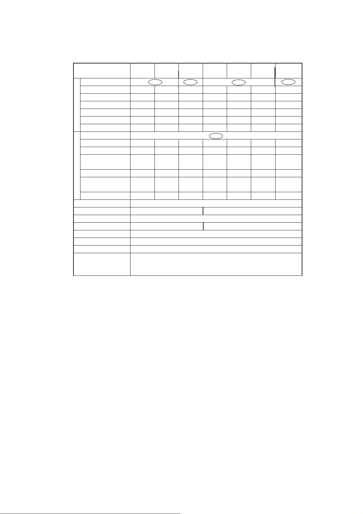
Reflex HP Series – EC Trade approved
with internal Calibration
Reflex HP Series
Trade Approved Models
Accuracy class Ⅱ Ⅰ Ⅱ Ⅰ
Capacity 820g 420g 620g 8200g 2200g 4200g 6200g
Verification scale interval (e) 0.1g 0.01g 0.01g 1g 0.1g 0.1g 0.1g
g
Number of verification scale interval
Scale interval (d) 0.01g 0.001g 0.001g 0.1g 0.01g 0.01g 0.01g
Range of use 0.5g-820g 0.02g-420g 0.02g-620g 0.1g-8220g 5g-2200g 0.5g-4200g 0.5g-6200g
Tare range (by subtraction) -820g -420g -620g -8200g -2200g -4200g -6200g
Accuracy class Ⅱ
Capacity N/A 2100ct 3100ct N/A 11000ct 21000ct 31000ct
Verification scale interval (e) N/A 0.1ct 0.1ct N/A 1ct 1ct 1ct
Number of verification scale
ct
interval
Scale interval (d) N/A 0.01ct 0.01ct N/A 0,1ct 0.1ct 0.1ct
Range of use
Tare range (by subtraction) N/A -1100ct -3100ct N/A -11000ct -21000ct -31000ct
Ambient operating temperature(°C) 10 - 30
Pan size (mm) approx. 108 × 105 170x180
Main body dimensions (mm) approx. 190W × 317D × 78H
Weight (kg) approx. 3.4 4,6
Display LCD with backlight
Power consumption DC12V, 1A
Data I/O RS-232C
HP820CT HP420CT HP620CT HP8200CT HP2200CT HP4200CT HP6200CT
8200 42000 62000 8200 22000 42000 62000
N/A 21000 31000 N/A 11000 21000 31000
N/A
0.2ct-2100ct 0.2ct-3100ct
N/A
N/A
5ct-11000ct 5ct-21000ct 5ct-31000ct
N/A
Features
WindowsDirect, PSC, Clock-CAL, GLP/GMP/ISO conformance, Analog display, % display, PCS,
Specific gravity measurement S/W, Checkweighing
3 - 2
Page 18

4. Installation
4.1 Choosing the Installation Site
(1) Power supply
• Select an installation site that is near a power source to ensure that the attached AC adapter is
used properly. If this is not possible, an optional battery pack is available as a special accessory.
• Verify that the supply power voltage conforms to that indicated on the AC adapter.
(2) Installation site
Caution
Avoid sites where the balance will be exposed to the following:
• Air flow from air-conditioner, open window, or
ventilator
• Vibration
• Direct sunlight
4 - 1
Page 19
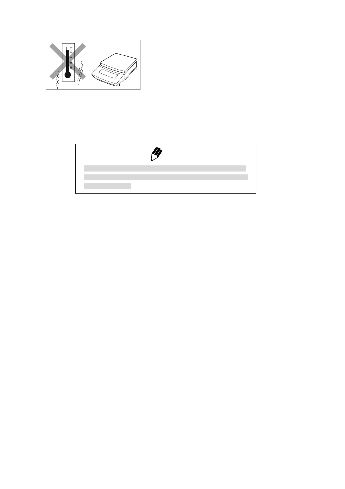
• Extreme temperature, temperature changes or
humidity
• Corrosive or flammable gasses
´ • Dust,wind, electromagnetic waves, or magnetic
fields fields
Note
Using a verified balance as a legal measuring instrument in the EU:
The balance must be used within the temperature range indicated on
the verification label.
4 - 2
Page 20
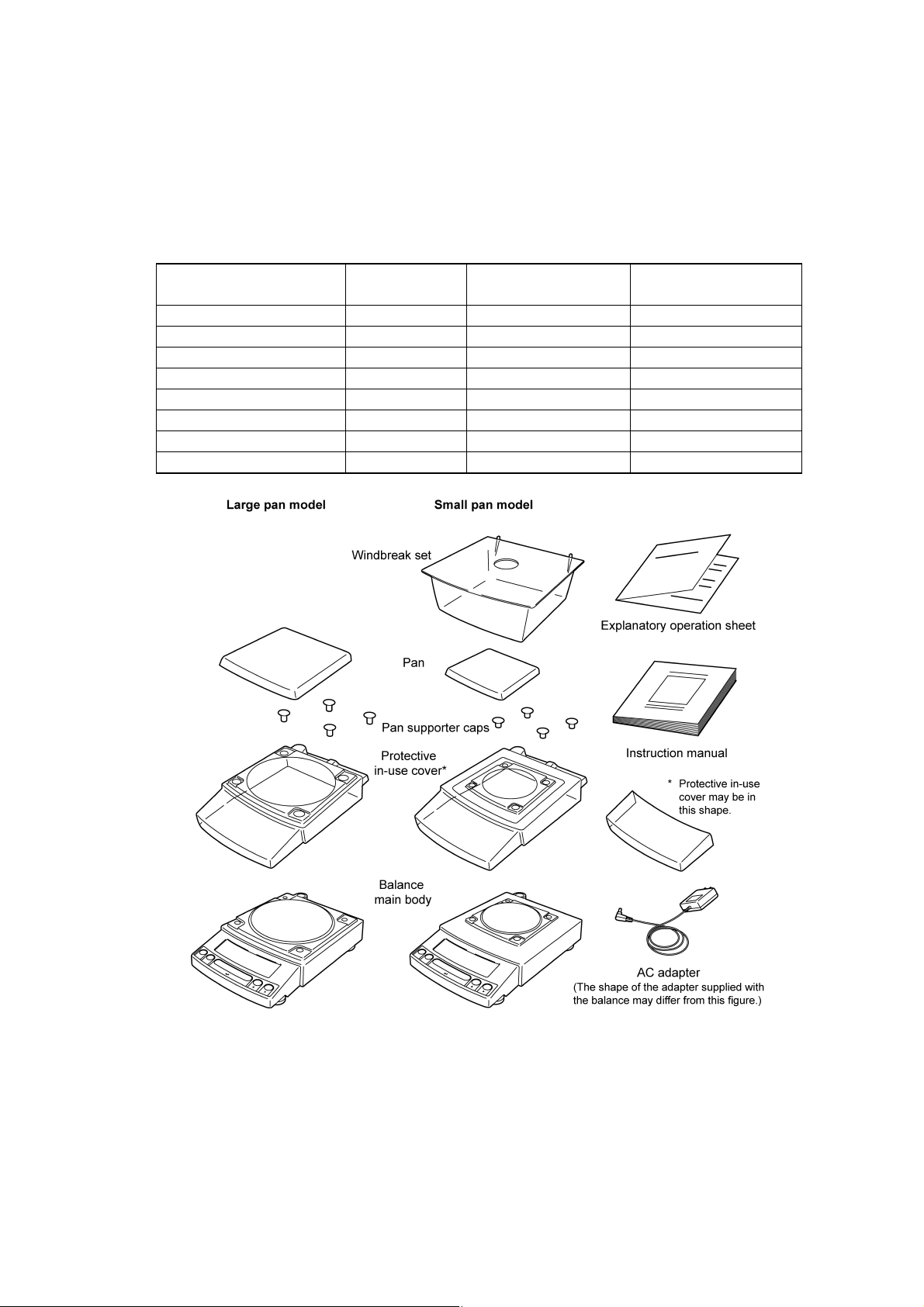
4.2 Unpacking and Delivery Inspection
Unpack and remove all the items from the delivery box. Check if all the listed items are present and
nothing has been damaged. Contact your local sales representative in case of damaged or missing
items.
Standard Packing List (Number of item)
Large pan model
Balance main body 1 1 1
Pan support cap 4 4 4
Pan 1 1 1
AC adapter 1 1 1
Protective in-use cover 1 1 1
Windbreak set 0 0 1
Instruction manual 1 1 1
Explanatory operation sheet 1 1 1
Small pan model
(Minimum display 0.01g)
Small pan model
(Minimum display 0.001g)
4 - 3
Page 21
4.3 Installation
(Start at step 3 when installing a HP (external calibration) series balance. You will need a Pozidrive
screw driver for a HPxxxC (internal calibration) series balance.)
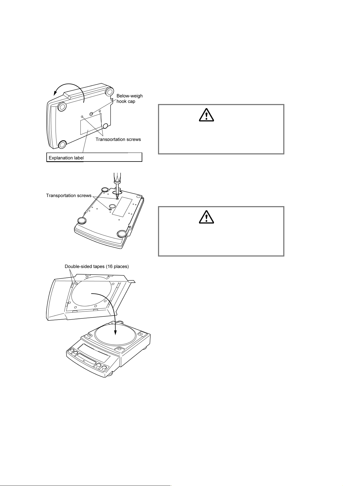
1 Place the balance main body upside down.
(HPxxxC only)
only for HPxxxC series
(only for HPxxxC series)
Caution
Do not operate step 2 with the balance placed
on its side.
Place the balance on a smooth surface.
2 Referring to the explanation label on the bottom of
the balance, turn the two transportation screws
counterclockwise until they tighten again. (HPxxxC
only)
Caution
When moving the balance again, turn the two
transportation screws clockwise until they
tighten. (HPxxxC only)
3 If you install the protective in-use cover, remove the
paper to expose the double-sided tapes on it and
place it on the balance main body. Press firm so
that the cover does not touch the pan.
[Large pan model]
[The shape of the protective in-use cover may be
different (See 4.2).]
4 - 4
Page 22
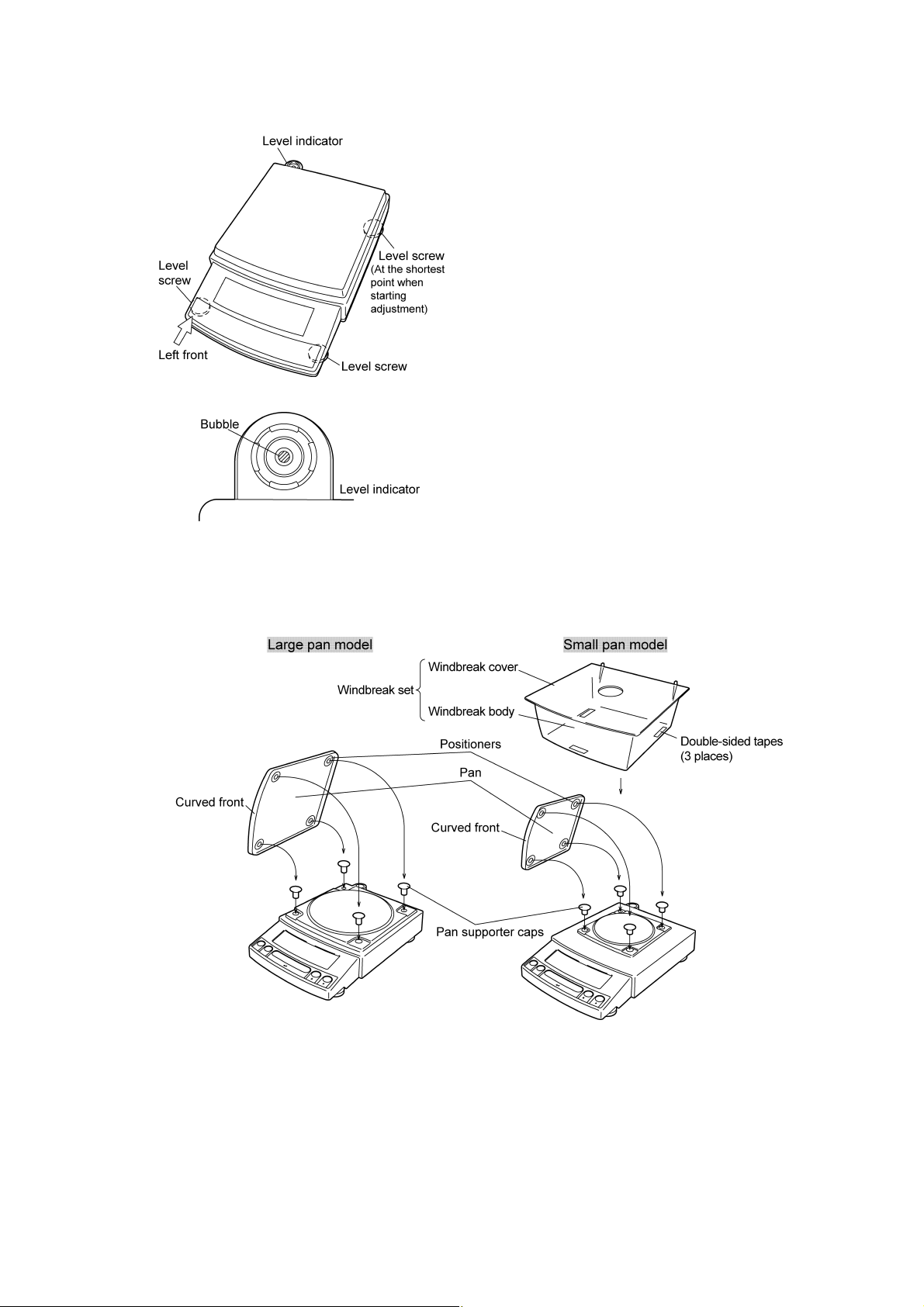
4 Adjust the level.
This balance has four feet, three of which are
adjustable. For efficient level adjustment, follow the
procedure below.
(1) First, verify that all three leveling screws are at
their shortest point.
(2) While lightly pressing down on the left front of the
balance, turn both of the front leveling screws to
bring the air bubble into the center circle of the
level indicator.
(3) Finally, while still pressing down on the front of
the balance, adjust the leveling screw at the right
rear of the balance until the balance is stable.
5 Insert the four pan supporter caps into the holes in
the top of the balance. Place the pan on top of them.
Positioners of the pan must fit pan supporter caps in
this operation.
6 Before mounting the windbreak, remove the paper
to expose the double-sided tapes on it. Attach the
windbreak to the top of the balance. The windbreak
is a standard accessory for models with a minimum
display of 0.001g.
4 - 5
Page 23

Note
Using a verified balance as a legal measuring instrument in the EU:
Legal regulations require a verified balance to be sealed. This control
seal is a self-destructive adhesive label. If you attempt to remove it, this
seal is irreparably damaged thereby invalidating the verification. The
balance must then be re-verified before it is used for legal
measurements.
4 - 6
Page 24
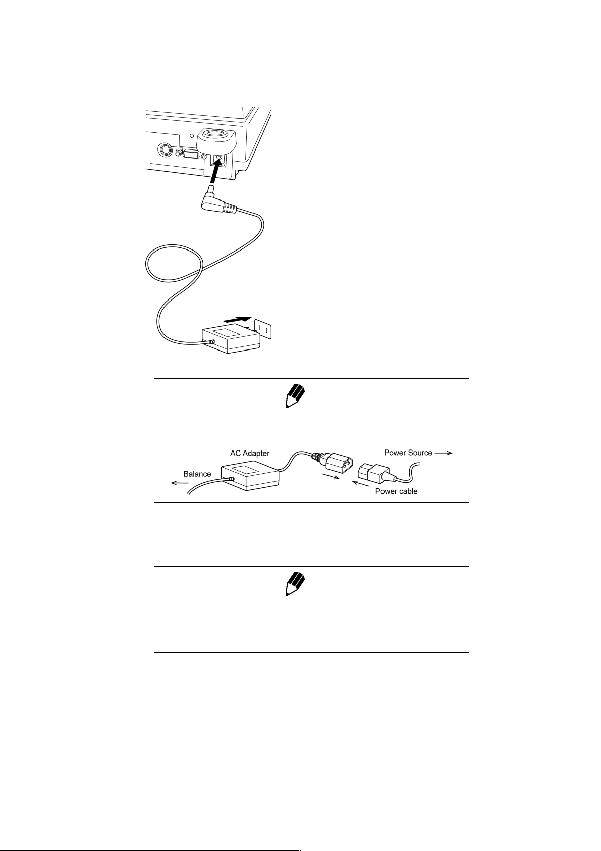
4.4 Turning On the Power
1 Insert the plug of the AC adapter into the DC IN
connector on the rear of the balance.
2 Insert the AC adapter into the power source. The
balance self-check is activated and the following
messages are displayed in the order indicated.
[HELLo], [CHE 5], [CHE 4], [CHE 3], [CHE2],
[CHE1], [CHE0], whole lighting, [oFF] ([CHE 5] and
[CHE 4] are not displayed for the HPxxx series).
Note
A power cable may be necessary to connect the AC adapter to the
power source, depending on the type of the AC adapter.
3 Press [POWER] key. The whole display illuminates
Note
When using the optional battery pack (special accessory), connect the
fully charged battery pack to the DC IN connector of the balance using
the cable attached to the battery pack.
and then the display changes to indicate the
gram-display. The backlight is illuminated.
4 - 7
Page 25
4.5 Span Calibration
Using a verified balance as a legal measuring instrument in the EU:
Span calibration must be performed once the balance is installed and
before using the balance as a legal measuring instrument in the EU.
Span calibration must be performed with the internal calibration weight
to maintain the verification valid. The balance must be connected to
power and warmed up for at least 2 hours prior to span calibration and
use as a legal measuring instrument.
It is necessary to calibrate the balance after it is moved.
Verify that the balance is stable before performing the span calibration. To achieve a very stable state,
ensure that the balance has been turned on with the gram-display for at least two hours, that the
temperature is constant, that there are no breezes or vibrations and that the balance is in an area
isolated from the normal traffic flow.
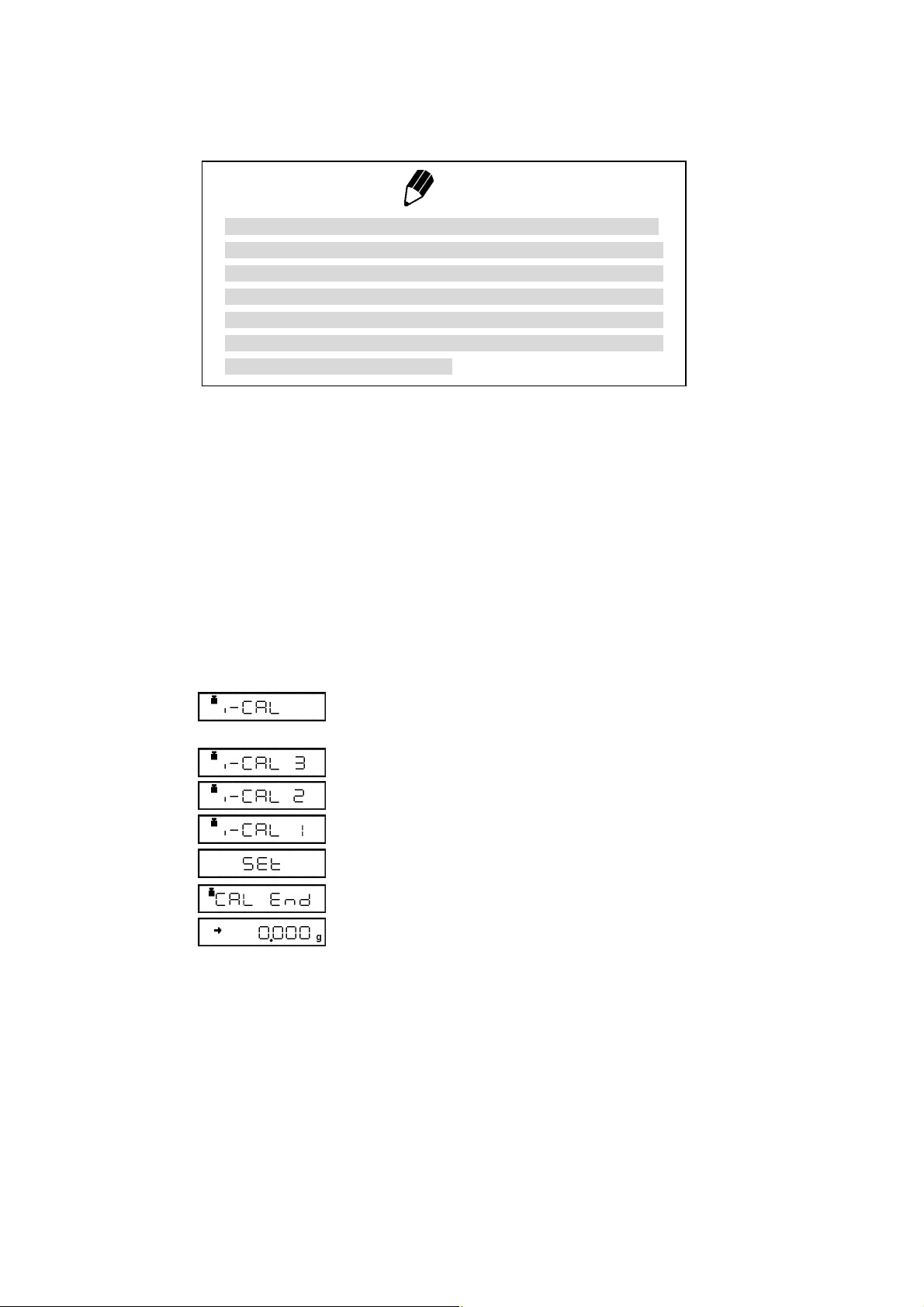
HPxxxC series [Span Calibration Using the Built-in
Weight]
1 Verify that the balance is in gram-display and that
Note
the pan is empty.
2 Press the [CAL] key once. “i-CAL” displayed.
3 Press the [O/T] key. After “i-CAL3” ... “i-CAL1”,
“Set”, “CALEnd” are displayed indicating the
completion of span calibration, the gram-display will
appear.
This is the standard calibration type. Refer to 10.3.1 for use of external weights.
4 - 8
Page 26
(Example)
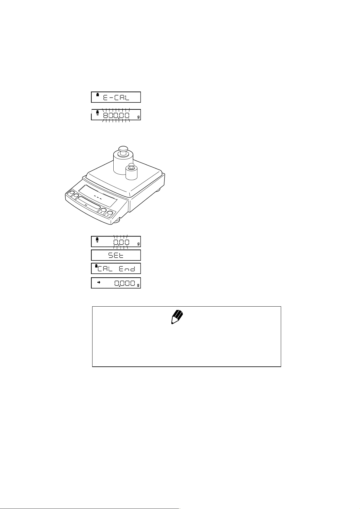
HP series [Span Calibration Using External Weights]
1 Verify that the balance is in gram-display and
unload the sample from the pan.
2 Press the [CAL] key once. “E-CAL” is displayed.
3 Press the [O/T] key.
The value of the correct calibration weight to be
loaded is displayed and blinks.
4 Load the indicated calibration weight and press the
[O/T] key.
5 When the zero display blinks, unload the weight
from the pan and press the [O/T] key. “Set” is
displayed briefly to indicate completion of span
calibration. Then the gram-display will return.
Span calibration is required again :
when the location of the balance is changed,
•
when the room temperature changes considerably,
•
periodically, according to the quality control plan of the user.
•
Note
4 - 9
Page 27
5. Basic Operation
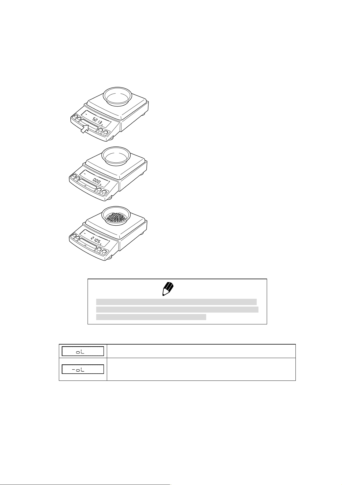
5.1 Weighing
1 If a weighing vessel (tare) is used, place it on the
pan and wait for the stability mark to illuminate.
2 Press the [O/T] key to zero the display. (This
operation is called “taring”.)
3 Place the object to be weighed on the pan.
Using a verified balance as a legal measuring instrument in the EU:
Indicates that the balance is set exactly to “Zero” with the zero-setting
function (+-0.25e: e = verification scale interval).
Error Displays During Weighing
Overload: Weighing capacity has been exceeded.
Negative Overload: The load on the balance is too light.
The pan is not adjusted properly.
4 Read the displayed value after the stability mark is
displayed.
Note
5 - 1
Page 28
5.2 Changing the default Unit Display
Every time the [UNIT] key is pressed, the unit display changes sequentially among those set-up in 12.1
Unit Display Set-up. Gram, %, and PCS have been set-up as default units before delivery.
Notes
• Before a unit can be displayed it must be registered in 12.1 Unit Display Set-up.
• The registered units are displayed sequentially according to the order of the 12.1 Unit
Display Set-up.
Using a verified balance as a legal measuring instrument in the EU:
The balance must be used within the temperature range indicated on the verification
label.
When PSC (refer to 10.3.2), fully-automatic span calibration, is not activated, operator
must carry out span calibration with the built-in weight (refer to 4.5) upon blinking of the
Weight Symbol.
Note
5 - 2
Page 29
6. WindowsDirect Function
6.1 Introduction: Experience it!
The Reflex HP series balance can transfer data directly to a personal computer running Lotus 1-2-3,
Excel, or other applications running on a Windows* operating system, as if the displayed value were
typed from the keyboard. This function is called WindowsDirect. Because this function directly accesses
the Windows operating system, communication software-installation troubles are eliminated. A cable
and a few simple settings are all that is needed to enable data transmission from the balance.
6.2 Set Up WindowsDirect
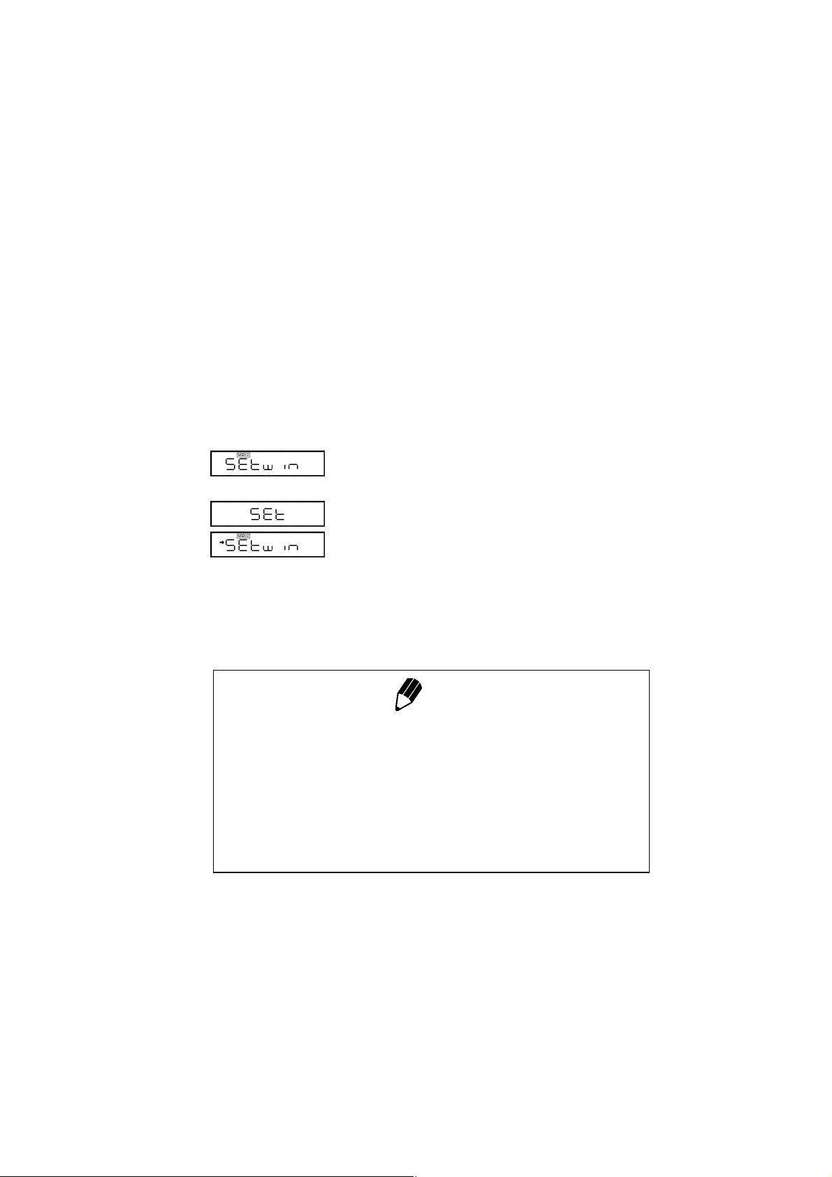
6.2.1 Setting Up the Balance
1 Press the [CAL] key twice from the gram-display.
“Setwin” appears.
2 Press the [O/T] key. Verify the stability mark is
illuminated with “Setwin” displayed. All the
communication settings for WindowsDirect have
been made.
3 Go to “STAND-BY” by pressing the [POWER] key
several times and unplug the AC adapter from the
balance. Unpluging the balance once is necessary
after the above setting.
Note
“Setwin” selects all the communication settings to enable
WindowsDirect function. However, the stability (arrow) mark at the
“Setwin” display is linked to the delimiter setting only. If any of the other
communication settings have been changed after the last set-up for
WindowsDirect, access the “Setwin” display and press [O/T] key to
cancel the stability mark once, then, repeat the setting up with “Setwin”
newly for WindowsDirect.
6 - 1
Page 30
6.2.2 Cable Connection
6.2.3 Setting Up the Computer
(leave the balance unplugged)
1 Verify the balance display is “STAND-BY”.
2 Turn off the computer and disconnect the power
cord from the balance.
3 Connect the RS-232C cable to the balance.
4 Connect the RS-232C cable to the computer.
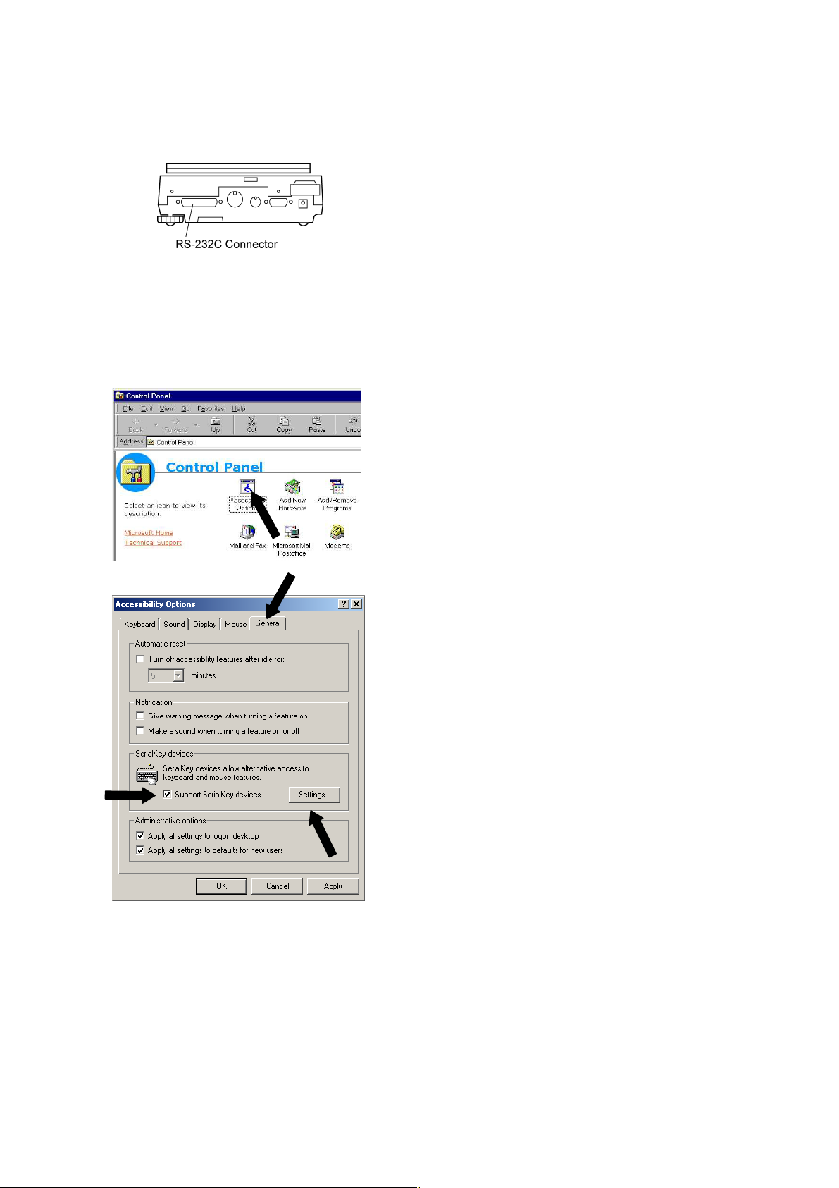
1 Turn ON the power to the computer and start
Windows*.
2 Click Start, choose Settings and Control Panel.
3 Select Accessibility Options.
4 Verify that there are no check marks for any items
on tabs including General.
5 Put a check mark at Support Serialkey device in
the General tab. This should be the only check
mark on all the tabs of Accessibility Options unless
Administrative options appears in the General
tab. Put check marks at both the items of
Administrative options to maintain the settings
even after restarting Windows.
6 Open Settings.
6 - 2
Page 31

7 Select the serial port corresponding to the RS-232C
port of your personal computer. (Serial port: any
one of COM1 to 4. Usually, COM1)
8 Select a Baud rate of 300.
9 Click OK.
10 Click Apply and wait.
11 Click OK.
12 Click Start, point to Shut Down then select Restart
the computer?.
It is not necessary to perform the Windows control
panel setting operation every time.
6 - 3
Page 32

6.2.4 Start and Checking Operation
1 Start Windows.
2 After Windows has completely started, connect
power cable from the AC adapter to the balance.
When the display shows “off”, press the [POWER]
key to show the mass display.
Note
Turning on the balance before Windows is completely activated may cause incorrect
operation.
3 Open the “Note pad” accessory in Windows
(or start the application you wish to use).
4 Press the [PRINT] key of the balance.
Verify that the numeric value displayed on the
balance appears at the cursor position on the
screen of computer.
5 Test combination with Auto Print function, if you
wish to use it.
6 End the operation using the standard close or exit
procedure.
Windows* = Windows 95, Windows 98, Windows Me, Windows 2000, Windows XP, and higher.
6 - 4
Page 33

6.3 Troubleshooting
Notes
• This function may not operate on a computer on which a normal U.S.
version of Microsoft Windows* does not operate. Some types of
personal computers may not be able to use this function or some
features may be limited. Avery Weigh-Tronix does not guarantee that
this function can be used on all computers without any problems
currently or in the future.
• Avery Weigh-Tronix is not liable for any direct or indirect problems
caused by this function. It is recommended that important data or
programs on your computer be backed-up before using this function.
For the operation of Windows or the computer, refer to commercial
tutorials or the appropriate instruction manual.
• It is necessary to have the “Accessibility Options” function of
Windows* installed on the PC. To install “Accessibility Options”, select
“Start”→“Setting”→“Control panel”→“Add/Remove Programs” and
open the “Windows Setup” tab. Place a check mark on “Accessibility
Options.” For more information, see the Windows* instruction manual.
• When “Support Serialkey device” is selected in Accessability
Options, software which uses the same RS-232C port on that
computer does not operate correctly, until Serialkey support is
discontinued. If another device (an external modem, plotter or etc.) is
to be connected, remove the check mark placed on “Support
Serialkey device” and re-activate Windows after the balance is
disconnected.
When the WindowsDirect Function Does Not Operate At All:
• For some notebook computers, it is possible to shut off the RS-232C port for energy saving
purposes. Set the computer so that the RS-232C port can be used.
• Try different COM port settings from 1 to 4. Re-start Windows after each setting change.
• Verify that the correct RS-232C cable is being used.
For Windows 98 and higher, try setting the computer again without restarting.
For Windows 95 Version 4.00.950B, see A-7., “Compatibility Notification Regarding Linking of
“WindowsDirect” Function with WindowsR95 Version 4.00.950B.”.
Communication through LAN by other applications may interfere with Serialkey device set-up. Try
without LAN connection.
Windows*= Windows 95, Windows 98, Windows Me, Windows 2000, Windows XP, and higher.
6 - 5
Page 34

When the WindowsDirect Function Intermittently Malfunctions:
• Use a communication speed of 300bps. Depending on the processing ability of the computer, this
function may operate incorrectly if communication speed is too high.
• Send the next data only after the current one is displayed on the screen. Depending on the
processing ability of the PC, this function may operate incorrectly if the interval of data transmission
is too short.
• Do not touch the keyboard or the mouse while the balance is transmitting data.
• Stop the data transmission and confirm that no data is entering the computer before touching the
keyboard or the mouse.
Notes
• This function may generate incorrect data when the displayed value
is not a weight value (i.e. error code or time).
• The unit designation is not transmitted. The balance display unit
selected and the unit required by the application should be set the
same.
• This function may operate incorrectly depending on the settings of
various lock keys of the keyboard such as the NUMLOCK or cursor
key lock. Change the state of the lock and function keys on the
computer keyboard.
• Peripheral devices connected to the DATA I/O such an Electronic
Printer cannot be used with this function.
• When this function is used, a command cannot be sent from the
peripheral device or computer to the balance.
• Set the data formats, such as decimal places and units, according to
each application.
6 - 6
Page 35

6.4 Notes on WindowsDirect
Compatibility Notification Regarding Linking of “WindowsDirect” Function with Windows 95
Version 4.00.950B
Microsoft Corporation announces that, when a personal computer’s SerialKey Devices are set up, an OE
error may occur, depending on the Windows 95 version.
Before setting up your personal computer for “Linking with Windows
Weigh-Tronix´s balances, be sure to check your Windows 95 version and take appropriate precautionary
measures according to this instruction, whenever required.
95” function of Avery
Caution
This information is provided only for the benefit of Avery
1
Weigh-Tronix customers. It is the responsibility of the customers to
take these precautionary measures on their own. Avery
Weigh-Tronix as well as Microsoft Corporation does not have any
responsibility for anything caused by the precautionary measures
here.
If you have attempted to setup SerialKey Devices without taking these
2
precautionary measures and Windows 95 will not start normally, follow
the procedure below:
• Restart your personal computer.
• While “Starting Windows
press
• Select [Control Panel] > [Accessibility Options] > [General] and
remove the check mark on the [Support SerialKey devices] check box.
• Restart Windows
1. Confirmation of the Windows 95 Version
• Click [Start] > [Settings] > [Control Panel].
• Double-click [System].
• Read the [General] tab's system information.
If it is:
go to “2. Precautionary Measures.”
If not, perform setup according to the instruction manual of your balance without taking
precautionary measures written here.
key and then select “3 Safe mode” to start up the system.
[F8]
95.
Microsoft Windows 95
4.00.950B
95...” is being displayed on the screen,
6 - 7
Page 36

2. Precautionary Measures
For Microsoft Windows
95 ver. 4.00.950B only.
1. Close all of active software applications.
2. Select [Start], designate the file name, and click on [Run...].
3. Enter “regedit” in the “Open:” field via the keyboard.
4. Click [OK], and the Registry Editor will start up.
5. Double-click “HKEY_LOCAL_MACHINE”
6. Double-click [System]/
7. Double-click [CurrentControlSet].
8. Double-click [Service].
9. Double-click [Vxd].
10. Double-click [VCOMM].
11. Double-click “EnablePowerManagement” located on the right window.
12. Edit “0000 01 00 00 00” to “0000 00 00 00 00.”
13. Click [OK].
14. Click [Registry], then choose [Exit Registry Editor].
15. Select [Start] > [Shut Down...] > “Restart the computer?” then click [Yes].
The precautionary measures are complete. Perform setup according to the instruction manual for the
balance.
This precautionary measure is effective automatically, whenever the Windows 95 system is restarted.
You will be required to perform the precautionary measure again if your Windows 95 system is
re-installed.
3. Reference
Microsoft Corporation provides information on this problem at the following site:
http://premium.microsoft.com/support/kb/articles/q170/8/45.asp/
6 - 8
Page 37

7. Menu Item Selection
7.1 What is the Menu?
The Reflex HP series balance has many functions that can be selected to meet the requirements of the
user. Menu Item selection is used to program these functions.
7.2 Menu Map
The menu of the Reflex HP balance consists of seven groups and four levels. The Menu Map shows the
structure clearly with menu item numbers to help access the desired function. Refer to the Menu Map on
the operation explanatory sheet or at the end of this section when programming the functions in Chapter 8
through 15.
7 - 1
Page 38

7.3 Menu Item Selection Procedure
This instruction manual identifies each menu item by a number. For example, the menu items of
“Stability Detection Band” of “section 11. Environment” are through . These numbers are also
shown on the Menu Map in section 7.6 and on the pull out Explanatory Operation Sheet.
Find the function to be programmed in the Menu Map, referring to the item number in square, .
To reach the item, operate the keys on the balance.
(1) Press the [CAL] key to access the menu.
(2) Press the [CAL] key to scroll to the next item on a menu level.
(3) Press the [O/T] key to select the current item, or to move to the next menu level.
(4) Press the [POWER] key to move back one menu level.
(5) Press and hold the [POWER] key to return to the gram-display.
3327
No.
Note
The symbol is displayed during Menu Item selection.
Example : To select Stability Detection Band, 4 Counts (item on the menu Map).
Note
Before entering the menu, set the balance to the gram-display using
the
weighing units involving no further setting with the
key. It is also possible to enter the menu from other
[UNIT]
1 Press the [CAL] key 5 times from the gram-display.
2 Press the [O/T] key. “E” is selected and “A” of
29
key.
[UNIT]
“Std:EAUS” and some symbols are displayed and
“E” flashes.
“E-AbtP8” flashes.
3 Press the [CAL] key to make “b” flashes.
4 Press the [O/T] key. “b” is selected and “Eb-1” is
displayed. The stability mark is lit if Eb-1 is the
currently set option.
5 Press the [CAL] key twice. “Eb-4” is displayed.
7 - 2
Page 39

6 Press the [O/T] key to select this item. “SEt” is
displayed and the stability mark now appears with
“Eb-4”.
7 Return to the desired menu by pressing the
[POWER] key. If pressed and held, it returns to the
gram-display.
Once the menu items have been set based on the installation environment and weighing purpose, it is
not necessary to select the menu items each time the balance is used. Once the contents of the menu
are set, they are stored even if the balance is turned OFF or if the power is disconnected.
Major Menu Description
Menu Group
1
2 (Graphic display) Analog display, checkweighing, and target weighing
3 E Installation environment and taring
4 A Application measurements and automatic output
Symbol that flashes at
beginning of menu
Calibration
Menu Items Included
5 U Unit conversion and specific gravity measurement
6 S Clock set-up and calibration record
7
Communication with computer and external devices.
7 - 3
Page 40

7.4 Setting Numeric Values
Some of Reflex HP series balance menu items require numeric value setting.
For example, external calibration weight input, thresholds for checkweighing, and reference density in
specific gravity measurements (see 10.2, 10.3, 13.1, 13.5, 14.1, 14.2, 14.4 for detail of each item.)
The values can be set using the balance keys.
In a menu used to set numeric values,
flashes.
…
and are both illuminated and the digit to be input
1 Press the [UNIT] key to increase the value of the
flashing digit by one. (0.....9, 0)
2 Press the [PRINT] key to move the flashing digit
one place to the right.
3 Press the [O/T] key to store the displayed value in
the balance memory.
“SEt” is displayed when the value has been
successfully saved.
“Err” is displayed when the balance failed to save
the value.
4 Press the [POWER] key to stop numeric entry.
“Abort” is displayed briefly and the display returns to
the menu, one level up.
Notes: Setting a Decimal Point
A decimal point is only used when setting units for solid density weighing,
liquid density weighing or when setting the multiplier for the user-defined
unit. Set the decimal point while setting numerical values as follows.
Press the
・
Press the
mode. The ▼ symbol or current decimal point flashes.
Press the
・
a time to the desired position.
Press the
・
“SEt” is displayed briefly to indicate that the setting is completed.
[PRINT]
[PRINT]
[UNIT]
[O/T]
key repeatedly until the last digit is blinking.
key once more to initiate decimal point setting
key to move the blinking decimal point one digit at
key to set the decimal point position.
7 - 4
Page 41

7.5 Related Useful Functions
7.5.1 Last Menu Recall
This function is convenient when an application requires frequent changes to a specific menu item.
During mass display or menu selection, press and hold the [CAL] key for approximately three seconds.
The last menu item that was changed or set is displayed.
7.5.2 Returning to the Default Settings (menu reset)
The procedure below describes how to reset the menu and return to the default settings.
Default settings are indicated with the ∗ symbol in the Menu Map.
Select menu item to reset the menu.
72
1 In the gram-display, press the [CAL] key repeatedly
until the “S” of “Std:EAUS” flashes.
2 Press the [O/T] key. The Menu Group 6 is selected.
3 Press the [CAL] key repeatedly until the “r” in
“S-dtSCr” is blinking.
4 Press the [O/T] key to display “rESEt?” (“?” without
the dot).
5 Press the [O/T] key again. “rESEt” is displayed to
indicate menu reset completion.
6 Press the [POWER] key several times (or hold it for
approximately 3 seconds) to return to the
gram-display.
7 - 5
Page 42

7.5.3 Menu Lock
The Reflex HP series balances have a “Menu Lock” function that locks the menu selections to avoid
accidental changes. WindowsDirect setting (6.2.1) is also locked.
The menu lock is toggled ON and OFF by pressing the [CAL] key during “oFF” display that appears after
power is supplied to the balance.
1 Connect the balance to the power.
2 Press the [CAL] key during “oFF” display.
“LoCKEd” is displayed to indicate that the menu is
locked.
Menu access is denied and “Err 22” is displayed when the user attempts to select a menu.
Use the following procedure to turn off the menu lock function and restore access to the menus.
1 Disconnect power from the balance and wait 10
seconds. Reconnect power to the balance.
2 When “oFF” is displayed, press the [CAL] key.
3 “rELEASE” is displayed to indicate that the menu
lock has been turned off.
7 - 6
Page 43

NAVIGATING THE MENU MAP
g
7.6 Menu Map
• Press the [CAL] key to access the menu.
• Press the [CAL] key to scroll to the next item on a menu level.
• Press the [O/T] key to select the current item, or to move to the next menu level.
• Press the [POWER] key to move back one menu level.
• Press and hold the [POWER] key to return to the gram-display.
• The text on the left of the menu map.
flashing
flashing
flashing
flashing
flashin
flashing
*Not applicable to a verified balance as a legal measuring instrument in the EU
Continued
No. : Menu item number
# : Default settings
7 - 7
Page 44

g
g
g
g
g
g
g
g
g
flashin
flashin
flashin
flashin
flashin
flashin
flashin
flashin
flashin
Continued
No. : Menu item number
# : Default settings
*Not applicable to a verified balance as a legal measuring instrument in the EU
7 - 8
Page 45

g
g
g
g
g
flashin
flashin
flashin
flashin
flashin
Continued
No. : Menu item number
# : Default settings
*Not applicable to a verified balance as a legal measuring instrument in the EU
7 - 9
Page 46

g
g
g
flashin
flashin
flashin
Continued
No. : Menu item number
# : Default settings
*Not applicable to a verified balance as a legal measuring instrument in the EU
7 - 10
Page 47

g
g
g
g
g
flashin
flashin
flashin
flashin
flashin
flashing
Returns to flashing
No. : Menu item number
# : Default settings
7 - 11
Page 48

7.6.1 Specifications of the RS-232C Connector
Pin number Use Name Function Remarks
1 RS FG Frame ground
2 RS TXD Data output
3 RS RXD Data input
4 RS RTS Internal connection with CTS
5 RS CTS Internal connection with RTS
6 RS DSR Handshake (receiving)
7 RS SG Signal grounding
8 NC NC Blank
9 Foot switch TARE External TARE To GND
10 NC NC Blank
11 NC NC Blank
12 NC NC Blank
13 Spare EXT Extension input Connection is prohibited
14 NC NC Blank
15 NC NC Blank
16 NC NC Blank
17 NC NC Blank
18 NC NC Blank
19 NC NC Blank
20 RS DTR Handshake (transmission)
21 NC NC Blank
22 NC NC Blank
23 NC NC Blank
24 NC NC Blank
25 Foot switch PRINT External PRINT To GND
7 - 12
Page 49

7.6.2 Table of Unit Conversion Information
Displayed during weighing
Displayed during Unit Display Set-up (See 12.1)
Display
Menu item
number
54 U- kg none kg* 0.001 0.00001
55 U- mg none mg* 1000 10
56 U- % none percentage ______ ______
57 U- pcs none piece counting ______ 1
58 U- ct none carat 5 0.1
59 U- mom none momme* 0.266667 0.005
60 U- ▼ d none solid specific gravity ______ ______
61 U- d none liquid density ______ ______
61a U- lb none Lb (pound)* 0.00220462 0.00005
61b U- oz none Oz (ounce)* 0.035274 0.0005
61c U- ozt none Ozt (troy ounce)* 0.0321507 0.0005
61d U-HK tl 1 Hong Kong tael* 0.0267165 0.001
61e U-HK tl 2,3,4
61f U-SPorE tl 2 Singapore tael* 0.0264554 0.001
61g U-twn tl 3 Taiwan tael* 0.0266667 0.001
61h U-twn tl 1,2,4 Taiwan tael* 0.0266667 0.0002
61i U- mAL tl 4 Malaysia tael* 0.0264600 0.0005
61j U-CHinA tl none China tael* 0.0266071 0.0005
61k U-CHinA tl 1,2,3,4 China tael* 0.0266071 0.001
61l U- dwt none dwt (pennyweight)* 0.643015 0.01
61m U- GN none GN (Grain)* 15.4324 0.2
61n U- t none tola* 0.0857339 0.001
62 U-USEr 4 User unit* ______ ______
Center section
(segmented
character
display)
Unit
display
section
Illuminated
triangular symbols in
the right end row of
the display;
numbered from 1 to 4
from the top.
Unit
Hong Kong
tael (jewel) *
Conversion
Coefficient
(1g=)
0.0267173 0.001
*Not applicable to a verified balance as a legal measuring instrument in the EU
Minimum
display in the unit
(models with
minimum display
of 0.01g, as
examples)
7 - 13
Page 50

8. Built-in Clock Set-up
The built-in clock has to be set up in advance if a calibration record is to be produced or Clock-CAL
function is to be used.
8.1 Date
(Example)
The built-in clock corrects for the leap year automatically.
・
The moment the [O/T] key is pressed to finish setting, seconds are
・
set to zero. If the date is set after setting the time, the second value
will be incorrect. It is important to set the Date first and then the
time, or to correct the seconds value using the ± second correcting
function described in section 8.3.
8.2 Time
1 Select menu item and set the last two figures of
the year, month and day, using the [UNIT] and
[PRINT] keys.
Example: May 15
Example: February 29
2 Then press the [O/T] key.
Notes
63
th
, 2002, set as “02.05.15”
th
, 2004, set as “04.02.29”
(Example)
The moment the
Select menu item and set the time in the 24
hour system using the [UNIT] and [PRINT] keys,
then press the [O/T] key.
Example: 1:23 in the afternoon, is set as “13:23”.
Note
key is pressed seconds are set to 00.
[O/T]
8 - 1
64
Page 51

8.3 Setting Display During Stand-by
Determine what is to be displayed during stand-by.
To display the time during stand-by, select menu item .
To display the date during stand-by, select menu item .
To display neither during stand-by, select menu item .
65
66
67
Notes
Convenient Functions of Time Display
The following functions are available when the time is displayed during
stand-by.
Seconds display function:
・
Press the
±30 seconds correction function:
・
Press the
between 00 - 29 seconds, the seconds are rounded down to zero. If
the value is between 30 - 59 seconds, the value is rounded up one
minute and 00 is displayed for seconds.
key to enable the display/non-display of seconds.
[UNIT]
key while seconds are displayed. If the value is
[CAL]
8 - 2
Page 52

9. Display Settings
9.1 Bar graph display
The relative amount of the load on the pan is displayed in the bar graph. This feature helps to prevent
errors due to OL (overload) status. This is called Full Scale mode. This display can not be used with the
Checkweighing or Target mode.
Select the menu item to set up Full Scale mode.
(Example)
To display no bar graph, select menu item .
9.2 Changing the Minimum Display Digit (10d:1d)
(1)
11
(2)
A bar displayed in the lower areas of the scale
indicates that the load on the pan is small. (1)
A bar displayed up to the upper areas of the scale
indicates that the load on the pan is close to the
weighing capacity. (2)
21
Not applicable to a verified balance as a legal measuring instrument in the EU
It is possible to decrease the resolution of the minimum balance display by one decimal place if
necessary.
1 Press and hold the [UNIT] key for approximately
three seconds. “- 10d -” is displayed and the display
is decreased by one decimal place.
2 Press and hold the [UNIT] key for approximately
three seconds. “- 1d -” is displayed and the display
returns to the original number of decimal places.
Note
The location of the decimal point in the display does not shift. In the
“10d” display, the last digit is empty.
9 - 1
Page 53

10. Calibration
10.1 What is calibration?
Calibration is required to accurately weigh items with an electronic balance. Calibration should be
performed:
• When the location of the balance is changed, even within the same room.
• When the room temperature changes considerably.
• Periodically, according to the quality control plan of the user.
Terms used in this manual:
Span Calibration: Adjustment of the balance to specifications using two weight values;
zero and an appropriate value for the balance capacity.
Calibration Check: Comparing the current calibration weight reading to the calibration
weight reading after the last span calibration.
Calibration: Pertains to both span calibration and calibration check.
Caution
Never turn off the balance when the following messages are displayed.
“i-CAL x”, “i-tESt x”, “wAit”, “Abort”, “CAL E x”(“x” represents a number).
With Reflex HPxxxC series, displaced built-in weight may cause
damage to the mechanism.
10 - 1
Page 54

10.2 Calibration Execution
10.2.1
Notes
• Setting before shipment is as the following:
Reflex HPxxxC series: Span calibration using the built-in weight
Reflex HPxxx series : Span calibration using external weights
The type of calibration can be changed (See 10.3).
• Calibration will not be performed when the weight on the pan is not
near zero, or the balance is not stable.
Span Calibration Using the Built-in Weight (Reflex HPxxxC
Series Only)
1 Verify that the balance is in mass display and that
the pan is empty.
2 Press the [CAL] key once. “i-CAL” is displayed.
(If “i-CAL” is not displayed, return to mass display
…
and select menu item .)
3 Press the [O/T] key.
After “i-CAL3”, “i-CAL2”, “i-CAL1”, “Set”, “CALEnd”
the mass display will appear indicating the
completion of span calibration.
1
10 - 2
Page 55

10.2.2
Series only)
Not applicable to a verified balance as a legal measuring instrument in the EU
Calibration Check Using the Built-in Weight (Reflex HPxxxC
1 Verify that the balance is in mass display and that
the pan is empty.
2 Press the [CAL] key once to display “i-tESt”.
(If “i-tESt” is not displayed, return to mass display
and select menu item .)
3 Press the [O/T] key.
The display changes sequentially from “i-tESt 2” to
the “d xxx” display. (xxx indicates a numeric value)
This “d” value indicates the difference between the
current calibration weight reading and the
calibration weight reading at the last span
calibration.
4 To perform span calibration, change the “d” value to
zero, by pressing the [CAL] key.
--Otherwise, Press the [O/T] key to avoid changing
the “d” value to zero. (Pressing the [POWER] key
interrupts calibration and does not change this
value to zero.)
“CALEnd” is displayed, indicating the completion of
the calibration check.
2
Note
Changing the “d” value to zero is equivalent to performing span calibration.
Notes
• Examples for interpreting the results of a Calibration Check:
“d” Value Actual Mass Displayed Mass
-0.3 3000g 2999.7(3200g/0.1g balance)
+0.21 400g 400.21(420g/0.01g balance)
• Error codes that may be displayed:
“d ouEr” (d OVER) indicates that the “d” value is 1000 counts or more.
“d UndEr” indicates that the “d” value is -1000 counts or less.
10 - 3
Page 56

10.2.3 Span Calibration Using External Weights
Not applicable to a verified balance as a legal measuring instrument in the EU
1 Verify that the balance is in mass display and that
the pan is empty.
2 Press the [CAL] key once. “E-CAL” is displayed.
(If “E-CAL” is not displayed, return to mass display
and select menu item .)
(Example)
Changing the Calibration Weight to be Used
Pressing the [CAL] key allows changes to the weight value. Modify the
value using the [UNIT] key and [PRINT] key, then press the [O/T] key.
To interrupt modification, press the [POWER] key.
3 Press the [O/T] key.
The value of the correct calibration weight to be
loaded is displayed and blinks.
4 Load the indicated calibration weight and press the
[O/T] key.
3
5 Shortly, zero display blinks. Unload the weight from
the pan and press the [O/T] key.
“SEt” is displayed briefly to indicate completion of
span calibration.
Note
OIML Class E2 or F1 calibration weight is recommended for calibration,
depending on your accuracy demand.
10 - 4
Page 57

10.2.4 Calibration Check Using External Weights
Not applicable to a verified balance as a legal measuring instrument in the EU
1 Verify that the balance is in mass display and that
the pan is empty.
2 Press the [CAL] key once to display “E-tESt”.
(If “E-tESt” is not displayed, select menu item .)
4
(Example)
Changing the Calibration Weight to be Used
Pressing the [CAL] key allows changes to the weight value. Modify the
value using the [UNIT] key and [PRINT] key, then press the [O/T] key.
To interrupt modification, press the [POWER] key.
Otherwise, press the [O/T] key to avoid changing the “d” value to zero. (Pressing the [POWER] key
interrupts calibration and does not change this value to zero.)
“CALEnd” is displayed, indicating the completion of the calibration check.
3 Press the [O/T] key.
The value of the correct calibration weight to be
loaded is displayed and blinks.
4 Load the indicated calibration weight and press the
[O/T] key.
The zero display blinks.
5 Unload the weight from the pan and press the [O/T]
key.
The display changes to the “d xxx” display.
(xxx indicates a numeric value)
6 To perform span calibration, change the “d” value to
zero by pressing the [CAL] key.
Note
Changing the “d” value to zero is equivalent to performing span
calibration. Refer to 10.2.2. for interpreting the results of a Calibration
Check.
10 - 5
Page 58

10.3 Calibration Setting
10.3.1 Selecting the Calibration Type
Not applicable to a verified balance as a legal measuring instrument in the EU
Set the calibration type that will be used in Calibration Execution.
To set up “Span calibration using the built-in weight”,(HPxxxC only) Select menu item .
To set up “Calibration check using the built-in weight”,(HPxxxC only) Select menu item .
To set up “Span calibration using external weights”, Select menu item .
To set up “Calibration check using external weights”, Select menu item .
1
2
3
4
10.3.2 PSC Fully-automatic Calibration (HPxxxC series only)
With the PSC function, span calibration is performed automatically using the built-in calibration weight
when the balance detects a temperature change that would affect weighing accuracy.
1 To turn ON the PSC function, Select menu item .
2 To turn OFF the PSC function, Select menu item .
Notes
• Blinking calibration symbol indicates an automatic calibration is
about to start.
• If PSC starts while the balance is in use, press the
abort that cycle.
[POWER]
key to
5
6
Notes
Using a verified balance as a legal measuring instrument in the EU:
When PSC, fully-automatic span calibration, is not activated, operator
must carry out span calibration with the built-in weight (refer to 10.2.1)
upon blinking of the Weight Symbol.
10 - 6
Page 59

10.3.3
Clock-CAL Fully-automatic Calibration (HPxxxC series
only)
Span calibration is performed automatically using the built-in calibration weight at up to 3 specific, preset
times during each day. The user selects the times. This function is named Clock-CAL.
It is possible to set up to three specific times for Clock-CAL (“ACALt1”, “ACALt2”, and “ACALt3”). Use
the 24 hour system to set menu items , , and . Setting to “00:00” releases the function.
To execute Clock-CAL, all of the following conditions must be satisfied at
the set time. If these conditions are not satisfied within one minute, the
automatic span calibration is not executed and that cycle is skipped.
• The balance must be in mass display or the standby mode.
• The balance must be stable.
(The stability symbol must be illuminated during mass display.)
• Load on the pan should be near zero.
• The balance should not already be in the process of span calibration.
Example: Setting “ACAL t1”to twelve noon.
7 8
9
Notes
1 Select menu item . 7
2 Set the desired time. (Refer to 7.4 for numerical
(Example)
Skipping Clock-CAL
If Clock-CAL starts while the balance is in use, press the [POWER] key to abort that cycle.
Turning Off Clock-CAL Function
When all three Clock-CAL times are set to “00:00”, the function is off.
input.)
3 Press the [O/T] key. The set time will be stored.
4 Proceed to next time setting by the [MENU] key, or
return by the [POWER] key.
10 - 7
Page 60

10.3.4
only)
Not applicable to a verified balance as a legal measuring instrument in the EU
PCAL is used to calibrate the built-in weight to a standard calibration weight that is correctly adjusted,
traceable and/or certified. The PCAL procedure is password protected. The administrator should set this
password (refer to 10.3.5).
PCAL: Calibration of the Built-in Weight (HPxxxC series
(Example)
Caution
Use a correctly controlled, precise calibration weight for this procedure.
If it is performed without a correct calibration weight, span calibration
and calibration checks using the built-in mass may not be correct in
subsequent operations.
1 Unload the sample from the pan and verify a zero
mass display.
2 Select the menu item .
“PAS: 0000” is displayed.
3 Enter the PCAL password using the [UNIT] and
[PRINT] keys, then press the [O/T] key.
The default password is 9999, set at shipment or
upon menu reset.
After “PCAL 3” is displayed, the value of the
standard weight to be loaded blinks.
4 Load the standard weight displayed, and press the
[O/T] key.
Soon, zero is displayed and blinks.
10
5 Unload the weight and press the [O/T] key.
The display proceeds to “PCAL 0”. When the mass
display appears, calibration is complete.
10 - 8
Page 61

Notes
• “SEt” is displayed during the process. Leave the balance in a stable
state until the mass display appears as in step 5.
• In PCAL, the value of the “weight to be loaded” cannot be changed.
• Set the PCAL password using menu item .
71
10.3.5 PCAL Password Setting (HPxxxC series only)
Not applicable to a verified balance as a legal measuring instrument in the EU
This password is necessary to access the PCAL function.
It is recommended that the balance administrator set this password to prevent an unauthorized person
from incorrectly calibrating the built-in calibration weight.
Select menu item . The numerical setting display appears.
Enter a 4-digit number from “0000” to “9999”
Refer to 7.4 for numerical input.
71
Note
When the menu is reset, the PCAL password is reset to “9999”.
10 - 9
Page 62

10.4 For GLP/GMP/ISO Conformance
These settings should be made by the administrator.
10.4.1 Calibration Report Setting
Calibration report setting turns function ON/OFF. Use this to generate and output a calibration report as
for GLP, GMP, or ISO9000. An electronic printer (optional accessory) is required to print the report.
To create calibration report, Select menu item .
To turn off calibration report function, Select menu item .
68
69
10.4.2 Balance ID Setting
Individual balances can be identified by the serial number on the main body of the balance. The user can
add a four-digit ID number to the calibration report.
Select menu item . Set a 4-digit number from “0000” to “9999”.
70
10 - 10
Page 63

11. Environment
11.1 Overview
Settings on the balance can be changed to compensate for the installation environment such as the
degree of vibration or air movement or for the purpose of weighing a solid, liquid or powder.
11.2 Stability and Response (Averaging)
It is possible to match the stability of the display and the degree of response with the requirements of
specific applications or the installation environment. One of five modes can be selected. Note that
adjustments for stability and response conflict with each other, although the Reflex HP series is
designed to meet both.
Auto mode: Select menu item .
The balance automatically performs optimum averaging dynamically while
observing the load data. This is the recommended setting and should be used
unless special circumstances exist.
Pouring mode: Select menu item .
This mode is only suitable for constant volume weighing of liquids or fluids.
This mode is very sensitive to wind and vibration.
Standard mode: Select menu item .
This mode is suitable for weighing in a normal environment. Averaging is fixed
and does not change dynamically as in the Auto mode.
Anti-vibration mode: Select menu item .
Use this mode when the balance is used in a location where there are large
vibrations and the display fluctuates in the Auto mode.
Response is deteriorated at small mass amount changes.
Anti-wind mode: Select menu item .
Use this mode when the balance is used in a location where it is exposed to
airflow that causes the display to fluctuate in the Auto mode.
Response deteriorates further than the Anti-vibration mode, but weighing is
comparatively stabilized.
22
23
24
25
26
Note
If weighing cannot be performed efficiently even with the Anti-wind
mode, change the installation site of the balance or use the optional
windbreak (large).
11 - 1
Page 64

11.3 Stability Detection Band
*Not applicable to a verified balance as a legal measuring instrument in the EU
The conditions for indicating balance stability can be selected. If “1 count” is selected, when the display
has remained constant (within one display count), the balance is regarded as stable and the stability
mark illuminates. Stability detection band settings can be selected from 2 to 64 counts.
Select menu item for “1 count”. for 2 counts, for 4, for 8, for 16*, for 32*, and
menu item to set the band as 64* counts.
33
32 31302928 27
Note
Use “16 counts” to “64 counts” only when the Auto Print function is used
and it is therefore required that the sensitivity to vibration be reduced to
allow the balance to be regarded as stable and print the measurement
value.
The balance may not operate properly if these settings are selected
under normal use conditions and environment.
11.4 Tracking
Tracking is the function that will maintain the current displayed value as long as possible.
To turn ON this function, Select menu item .
To turn OFF this function, Select menu item .
Zero Tracking Function
When the display is zero, tracking functions as “zero tracking” to keep the
zero display as long as possible. “Zero tracking” automatically cancels
small zero drift.
It is recommended to set tracking off when measuring slight mass change
such as in the process of drop addition or liquid evaporation.
34
35
Note
Using a verified balance as a legal measuring instrument in the EU:
Even when Tracking is ON, the range where it works is restricted to the
vicinity of the zero, and it is subjected to conditions, according to the
regulations.
11 - 2
Page 65

12. Units
12.1 Unit Display Set-up
Note
Using a verified balance as a legal measuring instrument in the EU:
Only g (gramme=gram), ct (carat) weighing units, percentage conversion
and piece counting are available for use. Carat is not available for
HP820CT and HP8200CT models.
The Reflex HP series balance can display weighed results in various weighing units. Refer to 7.6.2 for
details.
1 It is possible to display units other than “g”. Press
(Example)
When menu item (carat)
has been selected.
58
2 Before weighing, set the display units to be used.
the [UNIT] key in mass display to sequentially
change the selected units.
Gramme, %, and PCS (piece counting) are set up
before shipment. Set up the desired units by
selecting menu from to .
For details of PCS and specific gravity measurement,
refer to 13.2 and 14.1 to 14.2.
54 62
Notes
Error Display
For the unit names, refer to the menu map.
• In the unit setting menu, the stability symbol is illuminated to indicate
the currently set units.
• Set or release the unit by pressing the
displayed. Gram cannot be released.
User unit (menu item ): A numeric value (multiplier) is
62
key when the unit is
[O/T]
multiplied by the gram (g) weight of the unit.
Display Overload: This display appears if the mass display exceeds 7 digits
due to the choice of unit.
12 - 1
Page 66

12.2 Percentage (%) Conversion
1 Set the % unit with menu item if it is not set up.
The % unit is set before shipment.
2 Press the [UNIT] key several times in the mass
display until the % unit is displayed.
Setting the 100% reference
1 Press the [O/T] key to tare the balance.
2 Load the reference sample that corresponds to the
100% value. This value must be equivalent to 100
counts or more in the “g” unit.
3 When the stability mark illuminates, press the
[CAL] key.
“SEt” is displayed briefly and the reference sample
weight is displayed as 100%.
The weights of subsequent samples are displayed
as a percentage of the reference sample weight.
56
Note
The numbers of digits displayed in the % unit and rounding off of the
minimum digit vary depending on the mass value of the reference
sample and the balance model. It is not possible to obtain resolution
greater than that in the “g” unit.
12 - 2
Page 67

13. Enhancing Productivity
Functions that are useful mainly in production sites are described in this chapter.
Only one of the functions in the menu group 4 (Refer to 7.3) ( to ) can be used at a time. When
one of the functions in menu group 4 is to be used with a weighing unit other than gram, select the
function from the gram-display first. Then, change to the other unit with the [UNIT] key. To release this
function, use the [POWER] key. For returning to the previous function, Last Menu Recall function is
convenient. There are some other combinations of functions that can be used together. Some functions
employ the value set in Zero Range setting (refer to 13.5).
13.1 Checkweighing and Target Display
41 53
The Reflex HP series balance has an analog bar graph located on the left side of the display. This graph
can be conveniently used for checkweighing or cumulative weighing.
The graphic display functions include the two display modes of checkweighing, the target mode, and full
scale mode. Only one of them can be used at a time. Refer to 9.1 for the full scale mode and the no bar
graph display.
Upon selection of either the checkweighing mode or the target mode, the numerical value for threshold
or target is requested. Numeric values are memorized independently for each graphic display mode.
When one of the checkweighing modes is selected, a signal corresponding to HI, GO, or LO in
thegraphic display can be transmitted via the RS-232C/AUX connector.
Target, limit, upper, and lower values are set as numeric values only. Set the correct numerical value for
the unit that will be used for weighing.
• In weighing mode, changing the displayed unit does NOT change the target, limit, upper, or lower
numeric values. For example, when the upper limit has been set at 10g, switching the unit from “g”
to “kg” does not change the limit to 10kg. It will be 0.01kg.
The decimal point is invisible in the value setting display. Determine its position based on the resolution
of the balance. For example, if the balance’s minimum display is 0.01g, 150g must be set by inputting
“15000” in the display.
13 - 1
Page 68

13.1.1 Checkweighing (Comparator) Display Type 1
This is the best mode to determine pass or failure judgment based on the sample weight.
Displays in use
Determination as follows:
Sample weight
Lower threshold
Sample weight
Upper threshold HI
>
Sample weight ≤ Upper threshold GO
≤
Lower threshold LO
<
1 Select menu map item .
2 Set the upper threshold value, which corresponds
to the upper triangle mark, with menu item .
3 Set the lower threshold value, which corresponds to
the lower triangle mark, with menu item .
Note
15
16
17
13.1.2 Checkweighing (Comparator) Display Type 2
Use this mode for classification based on the sample weight. The display looks like a bar graph, but also
includes a checkweighing function.
Displays in use
Sample weight > Upper threshold HI
Lower threshold ≤ Sample weight ≤ Upper threshold GO
Sample weight < Lower threshold LO
1 Select menu map item .
2 Set the upper threshold value, which corresponds
to the upper triangle mark, with menu item .
3 Set the lower threshold value, which corresponds to
the lower triangle mark, with menu item .
13 - 2
18
19
20
Page 69

13.1.3 Target Mode
This mode is useful for constant amount weighing of liquid or judgment of excess and shortage.
The target value is the numeric value that is the desired amount in the unit that is used for weighing. The
limit value is the numeric amount above or below the target value that is acceptable. The target will be
indicated as the center line in the analog display. The limits will be indicated as triangle marks. A moving
bar represents the current weight on the pan.
Display examples in use
← target →
Without load With a load within
the limit range
1 Select the Target mode with menu item .
2 Set the “target” value, which corresponds to the
center line of the graphic display, with menu
13
item .
3 Set the “limit” value, which corresponds to the
distance between the center line and upper or lower
triangle marks, with menu item .
14
12
13 - 3
Page 70

13.2 Piece Counting (PCS)
(Example)
1 Set up the PCS with menu item if it is not set.
(The PCS unit is set before shipment.)
2 Press the [UNIT] key several times in the mass
display until the PCS is displayed.
3 Load the container and press the [O/T] key to tare
the balance.
4 Count exactly five pieces (or 10, 20, 50, 100, or 200
pieces) of sample to be measured and load them on
the pan.
5 Press the [CAL] key.
6 Every time the [CAL] key is pressed, the display
sequentially changes as
“Ld 5pcs”.... “Ld 200pcs”, “Ld 5pcs”...
The default setting is “Ld 10pcs”.
Press the [O/T] key when the display is equivalent
to the number of loaded pieces.
Example: If 50 pieces are loaded, press the [O/T]
key when “Ld 50pcs” is displayed. This
determines the unit weight or average
weight per piece.
As sample is added or removed, the
piece count (number of pieces) is
displayed.
57
Note
Repeat steps 3 through 6 above when the sample or manufacturing lot
is changed.
Piece Count Menu Display at Next Setting
In this example, when the [CAL] key is pressed in the next PCS menu,
display starts from “Ld 50pcs”.
13 - 4
Page 71

13.3 Auto Print
Auto Print function allows output of the data automatically without pressing the [PRINT] key for each
sample. The “Auto-Print” symbol is illuminated when the Auto Print function is activated.
Six types of Auto Print are possible. See 13.5 for Zero Range setting.
Print on loading: Select menu item .
Load the sample when the value displayed is within the Zero Range. When the stability
symbol has illuminated and the positive displayed value is more than 5 times the Zero Range,
data is automatically output.
The next data output is not performed unless the display has returned to a value within the
Zero Range by unloading the sample or pressing the [O/T] key.
Print on loading and unloading: Select menu item .
Load or unload the sample when the displayed value is within the Zero Range. When the
stability symbol has illuminated and the displayed positive or negative value is more than 5
times the Zero Range, data is automatically output.
The next data output is not performed unless the display has returned to a value within the
Zero Range by unloading the sample or pressing the [O/T] key.
Print on loading and on zero: Select menu item .
Load the sample when the value displayed is within the Zero Range. When the stability
symbol has illuminated and the positive displayed value is more than 5 times the Zero Range,
data is automatically output.
Unload the sample or press the [O/T] key. When the displayed value is within the Zero Range
and the stability symbol has illuminated, data is output again.
Print on loading, unloading, and on zero: Select menu item .
Load the sample when the value displayed is within the Zero Range. When the stability
symbol has illuminated and the displayed positive or negative value is more than 5 times the
Zero Range, data is automatically output.
Unload the sample or press the [O/T] key. When the displayed value is within the Zero Range
and the stability symbol has illuminated, data is output again.
42
43
44
45
Print continuously: Select menu item .
Not applicable to a verified balance as a legal measuring instrument in the EU
By pressing the [PRINT] key while the Auto-Print symbol and Stand-by symbol are lit, the
Stand-by symbol goes out, the Communication symbol lights and the displayed data is
continuously output.
Continuous output stops temporarily when the [PRINT] key is pressed.
46
13 - 5
Page 72

Notes
• During continuous output, the Communication symbol may appear to
remain lit. If the transfer speed of the data output is slow, the display
may flash. Increase the transfer speed as much as possible and set
the handshake off (menu item ).
• Pretaring Value (13.7) function cannot be used with Auto Print
functions.
73
Print on “GO” judge of checkweighing: Select menu item .
When the graphic display is in one of the checkweighing modes and the stability symbol lights
in the GO range, the data is output once.
The next data output is executed after the displayed value is within the Zero Range.
47
For automatic outputs at preset intervals, see 14.4 Interval Timer.
13.4 Auto Zero
Not applicable to a verified balance as a legal measuring instrument in the EU
When the displayed value is within the Zero Range and the stability mark has been illuminated, zeroing
occurs automatically. The Zero symbol appears in the display when the Auto Zero function is active.
Other keys function as expected with the Auto Zero function activated.
Select menu item to activate it.
41
13.5 Zero Range
The “Zero Range” value is used in some of the application functions as a reference to identify whether
the sample is loaded.
If the display is within the Zero Range, the balance determines that a sample is not loaded. If the display
goes more than five times the Zero Range it determines that a sample is loaded. Application functions
which involves judgment of whether a sample is loaded or not work in accordance with the Zero Range
setting.
Set the “Zero Range” value in menu item using the number of counts displayed in gram-display.
The setting range is 01 to 99 with 01 being the default value. Even when weighing will be done in
another unit, Zero Range setting is made by only gram value.
48
13 - 6
Page 73

Note
When a Pretare value is set, the value to determine that there is “no
load” becomes “- Pretare ± Zero Range” during gram-display. The Zero
Range function works as expected when attempting to weigh and Auto
Print the mass of a bottled sample during gram-display.
13.6 Taring/Printing at Stability
Not applicable to a verified balance as a legal measuring instrument in the EU
Determine if the balance should wait for stability before printing when the [PRINT] key is pressed or
displaying the zero point when the [O/T] key is pressed.
To print or tare without waiting for stability: (Immediately mode)
Select menu item .
To have printing or taring take place after the stability is detected: (Waiting for stabilization)
Select menu item .
39
40
Notes
While the balance is waiting for stabilization, ---- is displayed.
• When the
“---” is displayed. At this occasion, press the
desire to disable this function and abort taring.
• When the
Once the communication symbol and the Stand-by symbol are lit,
then stability mark is waited. The data will be output after the stability
mark is lit. If the
balance is brought to stand-by. The data will be printed upon stability
in the next weighing.
key has been pressed,
[O/T]
[PRINT]
key has been pressed,
[POWER]
[POWER]
key is pressed during the waiting, the
key if you
13 - 7
Page 74

13.7 Pretaring Value
Not applicable to a verified balance as a legal measuring instrument in the EU
Notes
• If the weight of the tare (container) varies, accurate measurement
with Pretaring Value function cannot made.
• Pretaring Value function cannot be used with Peak Hold,
Auto-Memory and Zeroing, Animal Weighing, or Auto function.
This function is used to weigh the mass of a sample packed in a container such as a bottle or
bag without opening the container. Pretare function should be used only if the mass of each
container does not vary from sample to sample. Instead of zero, the pretare value is displayed
(as a negative value) when the [O/T] key is pressed. The pretare value is then subtracted
from the total load on the balance pan to display the weight of the sample.
1 Select menu item .
2 Set the Pretare value. Refer to 7.4 for numerical
Pretare Value
Cancel the Pretare value by setting the value to zero.
When a Pretare value other than zero has been set, the Tare symbol
illuminates.
The Pretare value is set using the “g” unit. The maximum value is the
weighing capacity of the balance.
Check the Pretare value by pressing and holding the [O/T] key for
approximately 3 seconds during weighing.
36
value input.
13 - 8
Page 75

14. Application Functions
Application measurement functions are described in this chapter.
Only one of the functions in the menu group 4 (Refer to 7.3) ( to ) can be used at a time. When
one of the functions in menu group 4 is to be used with a weighing unit other than gram, select the
function from the gram-display first. Then, change to the other unit with the [UNIT] key. To release this
function, use the [POWER] key. For returning to the previous function, Last Menu Recall function is
convenient. There are some other combinations of functions that can be used together. Some functions
employ the value set in Zero Range setting (refer to 13.5).
14.1 Solid Specific Gravity Measurement
Solid specific gravity measurement refers to the measurement of the sample (solid) weight in the air and
in a liquid of known specific gravity (or density) and the calculation of the sample specific gravity (or
density).
The ▼d symbol is used to represent the solid specific gravity in this balance. The data output unit is DS.
41 53
Note
Use of the optional
Measurement Kit
using the SMK-101 or SMK-102, refer to the instruction manual of the
kit. Follow the instruction below when a hanging pan and a tank are
prepared by the user.
SMK-101, or SMK-102 Specific Gravity
is recommended for efficient measurements. When
1 Select menu item in advance.
Note
Enter the value of the specific gravity (or density (g/cm3)) of the liquid
(water, alcohol etc.) in which the sample is immersed. Refer to 7.4 for
numerical value input. To cancel the set-up, set the value to zero.
2 Remove the below-weigh hook cap from the bottom
60
of the balance to expose the below-weigh hook.
14 - 1
Page 76

3 Hook the hanging pan, and then immerse the
hanging pan in the tank filled with the liquid of
known specific gravity (or density).
4 From mass display, press the [UNIT] key several
times until ▼d (inverse triangle and “d”) is
displayed.
5 Press the [O/T] key.
6 Load the sample on the balance pan (or in the
hanging pan in air).
7 After the stability mark illuminates, press the [CAL]
key.
“dSP oL” may be displayed but this does not
indicate a malfunction.
8 Load the sample on the hanging pan immersed in
the liquid. The specific gravity (or density) of the
sample is displayed.
9 Repeat steps 5 through 8 for each additional
sample.
Notes
• Up to four decimal places are displayed for specific gravity. When it
is not possible to stabilize the balance in all 4 decimal places, use
the 1d/10d switching function.
• When loading the sample on the pan in the liquid, ensure that the
entire sample is immersed in the liquid.
• The balance does not re-zero when the
function.
key is pressed in this
[O/T]
14 - 2
Page 77

14.2 Liquid Density Measurement
Liquid density measurement refers to the measurement of the weight of a reference solid of a known
volume in air and in the sample liquid. Density of the liquid is calculated from these two values.
The display unit for liquid density is “d”. The data output unit is DL.
Note
Use of the optional
Measurement Kit
using the SMK-101 or SMK-102, refer to the instruction manual of the
kit. Follow the instruction below when a hanging pan and a tank are
prepared by the user.
SMK-101, or SMK-102 Specific Gravity
is recommended for efficient measurements. When
1 Select menu item in advance.
Note
Enter the value for the volume (cm3) of the reference weight. Refer to 7.4
for numerical value input. To cancel the set-up, set the value to zero.
2 Remove the below-weigh hook cap from the bottom
3 Hook the hanging pan, and then immerse the
61
of the balance to expose the below-weigh hook.
hanging pan in a tank containing the sample liquid.
4 From mass display, press the [UNIT] key several
times until “d” is displayed.
5 Press the [O/T] key.
6 Load the reference weight on the pan of the
balance.
7 After the stability mark illuminates, press the [CAL]
key.
“dSP oL” may be displayed but this does not
indicate a malfunction.
14 - 3
Page 78

8 Load the reference weight on the hanging pan and
immerse it in the sample liquid. The density of the
sample liquid is displayed.
9 Repeat steps 5 through 8 for each additional
sample.
Notes
• Up to four decimal places are displayed for density. When it is not
possible to stabilize the balance in all 4 decimal places, use the
1d/10d switching function.
• When loading the reference weight on the pan in the liquid, ensure
that the entire weight is immersed in the liquid.
14 - 4
Page 79

14.3 Peak Hold
Not applicable to a verified balance as a legal measuring instrument in the EU
Measures the displayed peak value. The “P” symbol (“P” of Auto-Print symbol) is illuminated when the
Peak Hold function is activated. “Peak value” is the highest or lowest stable value displayed after the
display has changed beyond five times the Zero Range.
Select menu item in advance.
49
1 In the peak detection standby state with the “P”
symbol and the Stand-by symbols illuminated,
press the [O/T] key to tare the display.
2 Press the [PRINT] key.
The Stand-by symbol disappears and peak value
detection starts.
3 The “P” symbol and Asterisk are simultaneously
displayed after the peak value is detected, and the
data is output. This display will not change
regardless of the load on the pan.
4 Press the [POWER] key.
The balance returns to the peak detection standby
state in step 1).
Notes
• Press the
initiate the power standby state.
• Press the
peak detection standby state.
• Polarity of the peak value displayed is “polarity of the displayed
value of the first change by five times or more of Zero Range from
the display within Zero Range.”
• Usually the peak value is easily measured by selecting menu
item (Pouring mode). Depending on the weighting conditions
and the sample type, this setting may not always be suitable.
• Pretaring Value (13.7) function cannot be used with Peak Hold
function.
[POWER]
[POWER]
23
key in the peak detection standby state to
key during detection of the peak to return to the
14 - 5
Page 80

14.4 Interval Timer
Not applicable to a verified balance as a legal measuring instrument in the EU
Automatically outputs the displayed value at preset intervals. The “T” symbol (“T” of the Tare symbol) is
illuminated when the Interval Timer is activated.
1 Select menu item and set the output interval
(00:01 = 1 sec to 99:59 = 99 minutes 59 seconds).
2 In the interval timer standby state when the “T” and
the Stand-by symbols are both illuminated, press
the [PRINT] key.
The first data is output. Data will be automatically
output at the set time intervals thereafter.
3 To stop output, press the [POWER] key.
The balance returns to the interval timer standby
state in step 1).
Notes
• Use the
• Pressing the
the power supply standby state.
• To release the interval timer function, keep pressing the
key. This does not reset the interval timer function to zero.
• Using the interval timer function to record data over a long period
may cause data error due to balance drift.
• Some instruments receiving the data may not operate normally if the
set time interval is short. To correct this, set the time interval to a
longer period. When the set time interval is short and the instrument
connected to DATA I/O is unknown, it is recommended to set the
handshake to a setting other than “H-tm” .
key to erase the tare or zero the balance at any time.
[O/T]
[POWER]
key in the interval timer standby state brings
76
50
[POWER]
14 - 6
Page 81

14.5 Auto-Memory and Zeroing
Not applicable to a verified balance as a legal measuring instrument in the EU
Used to weigh a large number of individual samples. The “Auto-Memory and Zeroing” symbol is
illuminated when this function is active.
Select menu item .
52
1 Load the weighing vessel and press the [O/T] key
in the Auto-Memory and Zeroing standby state
(The “Auto-Memory and Zeroing” and the Stand-by
symbols are lit).
Zeroing occurs.
2 Press the [PRINT] key.
The Stand-by symbol disappears, and Auto-Memory
and Zeroing measurement starts.
3 Load the first sample. Each time the stability symbol
is lit and the display is a value five times or more the
Zero Range or when the [PRINT] key is pressed,
the displayed value is output and zeroing occurs.
4 For the next sample, additional weighing is
performed without pressing the [O/T] key.
5 Press the [POWER] key.
The balance returns to the Auto-Memory and
Zeroing standby state and total mass on the pan
without the tare is displayed.
Press the [PRINT] key to print this value.
Notes
• When the stability symbol is illuminated and the displayed value is
within the Zero Range, zeroing occurs automatically.
• When the
than five times the Zero Range, zeroing occur after data output.
(Manual loading)
• When the
standby state, the power supply standby state is initiated.
• Pretaring Value (13.7) function cannot be used with Auto-Memory
and Zeroing function.
[PRINT]
[POWER]
key is pressed and the displayed value is less
key is pressed in the Auto-Memory and Zeroing
14 - 7
Page 82

14.6 Animal Weighing
Not applicable to a verified balance as a legal measuring instrument in the EU
Designed for weighing animals. The Animal symbol is illuminated when the Animal Weighing mode is active.
Select menu item .
53
1 Load the weighing vessel and press the [O/T] key.
Note
Data may be output when the weighing vessel is loaded. This is not a
malfunction.
2 Load the sample (animal etc.) with a mass more
3 When the weighed value is relatively stable, the
4 Press the [O/T] key or unload the sample.
5 When the displayed value is stable and less than 10
than 50 times the Zero Range.
value is automatically output.
times the Zero Range, automatic zeroing occurs.
Any residue remaining on the pan (excrement or
fur) is automatically canceled and zeroing occurs. If
zeroing does not occur, increase the value of the
Zero Range (13.5).
14 - 8
Page 83

Notes
• Standby state is not available in the Animal Weighing mode.
• Press the
• On the premise of weighing animated objects, the stability detection
band is automatically extended in the Animal Weighing mode.
Reproducibility of the measurement data is slightly less than with
other modes.
• When the animal being weighed cannot be controlled and the
automatic printing does not occur, press the
the displayed value. Then unload the animal. Even if the stability
symbol lights before the animal is removed, data is not printed again.
• By setting a larger stability detection band in the menu, the stability
symbol will light more readily.
• If the balance is slow to return to the zero point, set a larger Zero
Range value.
• Pretaring Value (13.7) function cannot be used with Animal Weighing
function.
[POWER]
key to initiate the power supply standby state.
[PRINT]
key to output
14 - 9
Page 84

15.
A variety of peripheral instruments are available for use with the Reflex HP series balance, such as an
electronic printer, keyboard or personal computer.
This chapter describes how to connect and communicate with peripheral instruments.
The details of the balance's communication settings are described in 15.3.
Connecting Peripheral Instruments
(For WindowsDirect, refer to 6. “WindowsDirect Function”)
15.1 Electronic Printer
1 For the balance, select the default communication
settings.
Menu item
number
Setting
76
Handshaking,
Timer
77 83 89 92 94
Format,
EB type
Baud Rate,
1200 bps
2 Disconnect the power to the balance and Electronic
Printer.
3 Connect the DATA I/O connector of the balance to
the printer using the optional cable of the printer.
4 First turn ON the power to the balance, then turn
ON the power to the printer.
Parity, None Stop bit, 1 bit Delimiter, CR
15 - 1
Page 85

15.2 Personal Computer - RS-232C -
∼
15.2.1 Connecting the Cable
Caution
Signals other than RS-232C are also output by the Reflex HP series
balances through the RS-232C/AUX connector. If these signal lines are
incorrectly connected, damage may occur to the personal computer or
balance. Correctly connect an appropriate cable for communication
between the balance and personal computer.
Some types of personal computers may not operate normally when
connected with the optional RS-232C cable according to the diagram.
(1) IBM PC/AT and compatible personal computer (D-sub 9-pin)
Personal computer side Balance side
1 1
2 2
3 3
4 4
5 5
6 6
7 7
8 8
9
20
22
FRAME
(2) IEEE Standard (D-sub 25-pin)
Personal computer side Balance side
1 1
2 2
3 3
4 4
5 5
6 6
7 7
20 20
SHIELD
FRAME
(This wiring cable is not always necessary.)
15 - 2
Page 86

15.2.2 Data Format
The following explanation is applied when menu item (Format EB type) is selected.
For other formats, refer to the data corresponding to the compatible machine.
indicates space code and <delimiter> indicates delimiter code.
(1) For the measured value
First character: Minus: '-' Non-minus: space
2nd to 11th characters: Numeric values or “ [“, ”]” are flushed right. The position of the decimal
point varies depending on the type of instrument.
12th to 13th characters: Unit such as g
14th to 15th characters: Delimiter
• When the delimiter is CR or LF (menu item or is selected)
the 13th character is not present.
• When printing stability information, the following characters are put
in front of the first character mentioned above.
Stable time: S
Unstable time: D
• When menu item or is selected for Delimiter, the special
format is used instead of that described above.
97
98
77
Note
or kg
Notes
95
94
(2) For “oL” or “-oL”
“oL”
“-oL” −
OL
OL
<Delimiter>
<Delimiter>
15 - 3
Page 87

15.2.3 Using Command Codes
Note
If communication conditions are incorrectly set, a communication error
message “ComErr” is displayed.
(1) Commands that end with a number, character, or symbol other than [=]: Transmit to the balance
with a delimiter for each command code.
Example 1: PRINT<CR> ... The same operation as pressing the [PRINT] key
(2) Commands that end with a [=]: Transmit the number to the balance with a delimiter.
Example 2: TIME=1234 <CR> .. 12:34 is set as the current time.
Example 3: P.TARE=1.23 <CR> (example of type of the second decimal place).
...1.23g is set as a Pretare value.
Example 4: P.TARE=0.00 <CR> (example of the second decimal place)
...Clears (cancels) the Pretare value.
Example 5: MENU=4630 <CR> (4-digit number after [=])
This is the same in the following operation.
.. from mass display, press the [CAL] key five times, then press the [O/T] key
once and the press the [CAL] key six times. This returns to the same display as
if the [CAL] key was never pressed.
Press the [O/T] key once, then [CAL] key three times, and the [O/T] key once
more.
This example indicates that menu item (Anti-vibration mode) is selected.
25
Notes
• If there is 0 in the four-digit number, the setting is complete at that
point and menu selection is ended.
• The result of this command varies depending on the type of the balance.
Example 6: #=2.56 <CR>
15 - 4
Page 88

Example 7: #=12.345.67 <CR>
A personal computer can instruct the weighing and display a specific number on
the balance.
With the commands in Example 6 &7, [#2.56] and [#12.345.67] are displayed on
the balance. When the operator presses the [PRINT] key, the character string
'2-56<CR>' and '12-345-67<CR> are output from the balance.
(3) Echo back command
The balance again transmits the character strings of N pieces included between an echo back
command ‘{‘ or ’}’ and the delimiter.
An unprocessed echo back command is not left in the receiving buffer of the balance, N ≤ 30.
Example 8: ABCDEFG12345<CR>
... After receiving this command, the balance outputs ABCDEFG12345<CR>.
The printer can print this character string.
Note
Only capital alphabets and a part of symbols (decimal point, symbol
etc.) can be used when printing with an electronic printer. A maximum
of 15 characters per line.
(4) Command codes for Format EB type (menu item ) and Format Old EB type (menu item )
(i) Commands related to output
D01 Continuous output *
D03 Continuous output with stability information *
D05 Single output
D06 Auto Print setting (type of Auto Print is set separately)
D07 Single output with stability information *
D09 Release of continuous output and Auto Print
*Not applicable to a verified balance as a legal measuring instrument in the EU
77 78
15 - 5
Page 89

(ii) Commands related to operation keys
POWER Equivalent to the [POWER] key.
Q Equivalent to the [POWER] key.
MENU Equivalent to the [CAL] key.
TARE Equivalent to the [O/T] key.
T Equivalent to the [O/T] key.
UNIT Equivalent to the [UNIT] key.
PRINT Equivalent to the [PRINT] key.
POWER+ Equivalent to holding the [POWER] key for approximately 3 seconds.
MENU+ Equivalent to holding the [CAL] key for approximately 3 seconds.
UNIT+ Equivalent to holding the [UNIT] key for approximately 3 seconds.
PRINT+ Equivalent to holding the [PRINT] key for approximately 3 seconds.
RECALC option unavailable
C option unavailable.
(iii) Commands related to application measurement
PEAK Sets the Peak Hold mode. *
AZERO Sets the Auto Zero mode ON. *
INTERVAL Sets the Interval Timer mode. *
ADDON Sets the Auto-Memory and Zeroing mode. *
+ Immediately operates after setting the Auto-Memory and Zeroing mode. *
A Sets the Animal Weighing mode. *
ANIMAL Sets the Animal Weighing mode. *
R Releases the Application weighing mode.
(iv) Commands related to unit conversion
g Switches to “g” unit.
kg Registration of “kg” unit and switching. *
mg Registration of “mg”unit and switching. *
PERCENT Registration of “%” unit and switching.
% Sets 100% when display is in “%” unit.
G g ← → % switching.
PCS Registration of “PCS” unit and switching.
CT Registration of “carat” unit and switching.
MOM Registration of “momme” unit and switching. *
SDENSE Registration of “solid density” unit and switching.
LDENSE Registration of “liquid density” unit and switching.
CU Switches to “user” unit (Set the conversion coefficient beforehand.). *
RSTUNIT Returns the default units.
*Not applicable to a verified balance as a legal measuring instrument in the EU
15 - 6
Page 90

(v) Readout commands of set value
TARGET Readout of target set value.
LIMIT Readout of limit set value.
G.LO Readout of lower limit set value in Checkweighing Display 1.
G.LO Readout of upper limit set value in Checkweighing Display 1.
L.LO Readout of lower limit set value in Checkweighing Display 2.
L.UP Readout of upper limit set value in Checkweighing Display 2.
UW Readout of unit weight set value.
G/PCS Equivalent to g/PCS key.
CALWT Readout of external weights set value for span calibration. *
ACALT1 Readout of Clock-CAL time 1.
ACALT2 Readout of Clock-CAL time 2.
ACALT3 Readout of Clock-CAL time 3.
P.TARE Readout of Pretare set value. *
ZRNG Readout of Zero Range set value.
USER Readout of user unit conversion coefficient. *
VOL Readout of reference weight set value.
DENSE Readout of surrounding liquid density set value.
I.TIME Readout of Interval Timer set value. *
(vi) Commands for numeric value setting
CALWT= Sets external weights value for span calibration. *
ACALT1= Sets Clock-CAL time 1.
ACALT2= Sets Clock-CAL time 2.
ACALT3= Sets Clock-CAL time 3.
P.TARE= Sets Pretare value. *
ZRNG= Sets Zero Range value.
UW= Sets unit weight.
USER= Sets user unit conversion coefficient. *
VOL= Sets volume of reference weight.
SDENSE= Sets surrounding liquid density.
I.TIME= Sets interval timer value. *
DATE= Sets the date.
TIME= Sets the time.
TARGET= Sets the target value.
LIMIT= Sets the limit value.
G.LO= Sets the lower limit value of Checkweighing Display 1.
G.UP= Sets the upper limit value of Checkweighing Display 1.
L.LO= Sets the lower limit value of Checkweighing Display 2.
L.UP= Sets the upper limit value of Checkweighing Display 2.
PCS= Sets the arbitrary loading piece.
#= option unavailable.
ID= Sets ID.
PASSSET= Sets PCAL password. *
PASS= Inputs PCAL password. *
*Not applicable to a verified balance as a legal measuring instrument in the EU
15 - 7
Page 91

(vii) Commands of special functions
CAL Enters Span Calibration mode.
C18 Enters Span Calibration mode.
LOCK Sets menu lock.
RELEASE Releases menu lock.
TIME Readout of date and time.
ADJCLK Adjusts ± 30 seconds.
RSTMN Menu reset.
MENU= Sets arbitrary menu.
{ Echo back.
} Echo back.
[α] Sets to Multi-Connection mode. (α represents a lower-case alphabet character.)
Note
For Multi-Connection mode, refer to Section 15.2.4 “Multi-Connection
Mode”.
15 - 8
Page 92

15.2.4 Multi-Connection Mode
A maximum of 26 Reflex HP series balances can be connected to one personal computer at the same
time. This is called “Multi-Connection mode.” To use the balance in this mode, prepare RS-232C cables
in the number of balances connected, and the optional IFB-102A RS-232C Interface.
Connecting Method
Example for connecting 10 units of Reflex HP series balances to one personal computer is shown in the
diagram below.
Assignment of Identification Name
In this example (10 balances connected to one computer), assign the identification name in lower-case
alphabets.
Since 10th character of alphabet is “j,” assign “j” to the balance closest to the personal computer, “i” to
next closest balance, and so on, back to “a.”
Setting to Multi-Connection Mode
Personal computer IFB IFB
Reflex HP
] ] ]
Reflex HP Reflex HP
1 Adjust the communication menu settings of all the
balances to the specification of the personal
computer, and then, turn off the power to all
balances.
2 Start supplying the power to the whole system. Wait
until all balances display OFF.
3 Send “[α] <delimiter>” from the personal computer.
α is the name of the balance next to the personal
computer. In the example above, lower-case “j.”
This command is valid only one time after turning
the power ON.
Respective balances automatically enter the
Multi-Connection mode and the mass is displayed.
On this process, the name smaller than the sent
command by one, i.e. “[i] <delimiter>”, is returned.
15 - 9
Page 93

4 This procedure completes the setting to the
Multi-Connection mode.
BALANCE (No) Command (PC) RETURN DATA (PC)
a [a] PRINT [a] PRINT
0.0g
b [b] PRINT [b] PRINT
0.0g
c [c] PRINT [c] PRINT
0.0g
d [d] PRINT 0.0g
(nearest to PC) (No Data)
Command Codes in the Multi-Connection Mode
Only the commands shown below are valid in the Multi-Connection mode.
(α is the name of the balances.)
[α]TARE Same as the operation of pressing the [O/T] key of the balance “α”.
[α]T Same as the operation of pressing the [O/T] key of the balance “α”.
[α]POWER Same as the operation of pressing the [POWER] key of the balance “α”.
[α]Q Same as the operation of pressing the [POWER] key of the balance “α”.
[α] PRINT Same as the operation of pressing the [PRINT] key of the balance “α”.
[α]D05 Same as the operation of pressing the [PRINT] key of the balance “α”.
[α]D07 Same as sending the D07 command to the balance “α”.
[α]UNIT Same as the operation of pressing the [UNIT] key of the balance “α”.
[α]CAL Same operation as sending the CAL command to the balance “α”.
[α]UNIT+ Same as the state of holding down the [UNIT] key of the balance “α”.
Format of Output Data from the Balance
The output data from the balance “α” is performed with the following format.
“[α]” data <delimiter>
Format of the load data is the same as the normal output form (Format EB type).
Operation is not guaranteed for the data containing characters, such as printing of date, time, and
calibration document etc.
15 - 10
Page 94

Restricted Items in the Multi-Connection Mode
• Multi-Connection mode is not designed for each balance to independently send the data.
This mode is for sampling the data by control of multiple balances with one PC. This is not the function
to support multiple balances for sending the data separately.
When multiple number of data and commands exist on the system at the same time, the balance may
not operate normally. For example, multiple data may exist simultaneously on the system when using
multiple balances in the Application Measurement mode such as Auto Print or Continuous Output, or
pressing the [PRINT] key. Normal operation cannot be guaranteed.
• Peripheral instruments connected to the DATA I/O or IFB-102A connector, such as an Electronic
Printer, cannot be used.
• The communication formats can only be used with “Format EB type”. Delimiters cannot be used with
menu items or (setting for WindowsDirect).
• It will take an average 0.05×N seconds for the data from the personal computer to reach balance unit
N, even at setting of 38400 bps. Also, it will take almost the same time for the data from the balance in
the Nth position to reach the personal computer.
97 98
Cancellation of Multi-Connection mode
Multi-Connection mode cannot be canceled unless the power for all balances is turned OFF.
15 - 11
Page 95

15.3 Communication Setting
15.3.1 Overview
This menu is used to set the specifications for communication between the balance and a personal
computer or electronic printer.
Note
This menu affects both the RS-232C and DATA I/O at the same time.
For the instrument to be connected to the DATA I/O connector such as
an electronic printer, select the communication setting of the balance to
the default settings, which are menu items , , , , , .
76
77 89 92 94
83
15.3.2 Handshaking
Handshaking determines whether the peripheral equipment can receive communication data from the
balance. This function does not relay the status of the balance to the peripheral equipment.
The balance is able to receive as long as there is space in the receiving buffer of the balance. This
function operates once “oFF” is displayed, operation in other states is not guaranteed.
When the balance output is retained by handshaking, the display of the balance is locked. Determine the
specifications for handshaking.
To have software handshaking not performed, select menu item .
To have software handshaking performed as the following, select menu item .
After the balance receives X-OFF (13H), the balance output is retained.
After the balance receives X-ON (11H), the balance output is initiated.
73
74
To have hardware handshaking performed as the following, select menu item .
When DTR is OFF, the output from the balance is retained.
When DTR is ON, the output from the balance is initiated.
To have timed hardware handshaking performed, select menu item .
76
75
15 - 12
Page 96

15.3.3 Format
Set the balance output data format.
The standard format for the Avery Weigh-Tronix balance: Select menu item .
Note
In this format, the number of the lowest place of menu item is
assigned to identify the balance.
70
15.3.4 Communication Speed
Select the communication speed (300, 600, 1200, 2400, 4800, 9600, 19200, or 38400 bps).
Number of “b-xxx” shows bps (bits/second). Baud rate and bps are the same value.
88
Select one of the menu items to .
81
15.3.5 Parity / Bit Length
77
Select the parity and bit length.
No parity, 8-bit length: Select menu item .
Odd number parity, 7-bit length: Select menu item .
Even number parity, 7-bit length: Select menu item .
15.3.6 Stop Bit
Select the number of stop bits.
Stop bit 1: Select menu item .
Stop bit 2: Select menu item .
89
90
91
92
93
15 - 13
Page 97

15.3.7 Delimiter
The “delimiter” is used to separate individual pieces of data or commands. Set the delimiter as follows:
Set to CR(0DH): Select menu item .
Set to LF(0AH): Select menu item .
Set to CR+LF(0D0AH): Select menu item .
Transfers the data directly to Microsoft Windows. This is equivalent to pressing the Enter
key of the personal computer: Select menu item .
Transfers the data directly to Microsoft
cursor key of the personal computer: Select menu item .
Settings for “WindowsDirect” (menu items and .)
When these menu items are selected, it is not possible to send
commands to the balance from the peripheral instruments. The personal
computer and electronic printer cannot be used at the same time.
Windows. This is equivalent to pressing the right
Note
97 98
94
95
96
97
98
15 - 14
Page 98

16. Maintenance and Transportation
16.1 Maintenance
Use a soft damp cloth containing a neutral detergent to clean the balance.
Avoid using organic solvents, chemicals, or dusting sprays as they may damage the coatings of the
balance or the display panel.
Attach the protective in-use cover (standard accessory) when the balance is used in an environment
where it is susceptible to being soiled.
The pan can be removed and washed with water. Verify that the pan is completely dry before replacing it
on the balance.
16.2 Moving the Balance
To carry the balance, hold the balance firmly with both hands.
To transport the balance, use the shipping carton used to deliver the balance.
For Reflex HPxxxC balances: Before placing the balance into the shipping carton, remove the pan and
pan supporter caps and verify that the transportation screws in the
bottom of the balance have been tightened clockwise until they stop.
Refer to 4.3.
For Reflex HPxxx balances: Remove the pan and pan supporter caps and place the balance in the
packing case as it was shipped.
Caution
Failure to tighten the transportation screws, placing the balance on its side when
turning the transportation screws, or failing to remove pan supporter caps before
placing the balance upside down may cause serious damage to the mechanism.
Notes
Using a verified balance as a legal measuring instrument in the EU:
Span calibration must be newly performed with the built-in calibration weight after the
balance has been moved and re-installed, before using the balance as a legal
measuring instrument in the EU.
16 - 1
Page 99

17. Troubleshooting
17.1 General Display
Display Description of message
Wait for next display.
Minimum display resolution is decreased by one decimal place. *
Minimum display digit is returned to original state. *
Date and time are being output.
Operation was aborted.
Application Measurement was released.
Calibration check detects too large error. (Contact your Avery Weigh-Tronix
representative.)
Calibration check detects too large error. (Contact your Avery Weigh-Tronix
representative.)
Menu lock is applied.
Menu lock is released.
Menu was reset.
Contents of new setting and coefficient were stored.
Reset by power failure.
Built-in weight is moving. Wait.
All numerals blinking Place the displayed calibration weight.
*Not applicable to a verified balance as a legal measuring instrument in the EU
17 - 1
Page 100

17.2 Error Display
Error display Description Countermeasure
Trouble in weight loading mechanism Check transportation screws.
The load on the pan is unstable at
calibration.
The drift of zero point is large at
calibration.
The drift is large at the time of PCAL. Use correct weight.
The drift is large at span calibration. Use correct weight.
Calibration weight is wrong. Use correct weight.
Failure in the balance
(Stops when this is displayed)
Received command code is not
correct.
Integer of the displayed unit exceeded
7 digits.
Failure in the balance. *
PCAL password error. Check the password.
Attempted to set improper numeric
value.
[CAL] key was pressed during menu
lock.
Supply voltage is abnormal. Check the supply voltage.
Avoid wind and vibration.
Empty the pan.
*
Check delimiter etc.
Decrease the load.
Review the numeric value and decimal
places.
Release menu lock.
17 - 2
* Contact your Avery Weigh Tronix
representative.
 Loading...