

Page 1
High Capacity Electronic Balance
Reflex HC Series
HC12000, HC32000, HC52000
User Instructions
ENGLISH
76103-920 Issue 1 09.03.2004
C
Page 2
$YHU\%HUNHO/LPLWHG$OOULJKWVUHVHUYHG
The information contained herein is the property of Avery Berkel Limited and is supplied
without liability for errors or omissions. No part may be reproduced or used except as
authorised by contract or other written permission. The copyright and the foregoing
restriction on reproduction and use extend to all media in which the information may be
embodied.
Avery Weigh-Tronix is a trading name of Avery Berkel Limited
7UDGHPDUNVDQGDFNQRZOHGJHPHQWV
Avery, Avery Berkel, Avery Weigh-Tronix are registered trademarks in certain jurisdictions
and owned and registered by companies within the Avery Weigh-Tronix Group.
All brands and product names used within this document are trademarks or registered
trademarks of their respective holders.
,03257$17
When programming or configuring the equipment you must ensure that you comply with all
relevant standards and legislation. The example settings given in this book may not be
legal for trade with the public.
Page 3
Declaration of Conformity
Manufacturer : Avery Weigh-Tronix
Type: HC
corresponds to the requirements of the following EC directives:
EMC Directive 89/336/EEC
Low Voltage Directive
The applicable harmonised
standards are:
A copy of the original signed declaration for this instrument is available from:
Avery Weigh-Tronix, Foundry Lane, Smethwick, West Midlands B66 2LP England
73/23/EEC
EN60950, EN45501,
EN55022, EN55024, EN61000-3
Reflex HC Series
3
Page 4
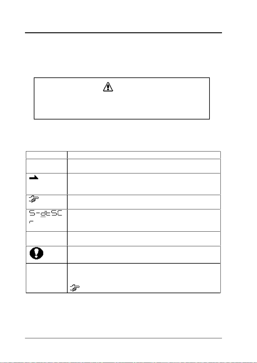
Notation Conventions
This instruction manual uses the following notation conventions to
indicate Safety Precautions.
CAUTION
Indicates a potentially hazardous situation that may result in
injury to personnel or equipment damage.
Note: Provides additional information needed to properly use the
balance.
Other conventions used in this manual include:
ITEM DESCRIPTION
1) 2) 3)…
etc.
mass display Indicates the balance is in the weighing mode and
Indicates the step number in a procedure or a
sequence of changes in the balance display.
Indicates the display change or action sequence
performed by the balance after an operation has been
initiated.
Refer to the recommended sections for further
information on a specific topic.
Indicates the balance display status.
Underlined portions (_) indicate that the character is
flashing.
mass is displayed in one of the weighing units.
These sections include information to make using the
balance more convenient.
Menu Map
item [1]
4
Indicates the Menu Map item to be selected.
The number inside the [ ] is the number of the item on
the Menu Map.
See Section 2.3 "Menu Map."
Reflex HC Series
Page 5
SAFETY PRECA UTIONS
To ensure safe and proper operation of the balance, observe
the following precautions.
Do not use the balance in hazardous areas.
This includes areas where the balance is exposed to dust or
flammable gases and liquids.
Use the AC adapter specified by Avery Weigh-Tronix.
To prevent electric shock, never disassemble the AC adapter.
The AC adapter is designed for indoor use. Do not use the
AC adapter in exterior environments or where it may be
splashed by water.
Ensure that the power supply voltage meets the indicated
range of the AC adapter.
Handle the balance carefully.
The balance is a precision instrument of solid design.
Do not connect peripheral devices other than those
recommended by Avery Weigh-Tronix.
The balance may not operate properly if peripheral devices
other than those specified in this manual are used. The
specifications for the RS-232C/AUX connector are described
in Section 3.2 "Personal Computer - RS-232C". Connect the
peripheral devices according to the methods described in this
instruction manual.
DO NOT disassemble the balance, accessories, or peripheral
unit.
Reflex HC Series
5
Page 6
Contents
Declaration of Conformity.......................................................3
1 Basic Operation...................................................................10
1.1 Balance Components ....................................................10
1.1.1 Operations of the Keys on the Main Unit ...............................11
1.1.2 Symbol Display .......................................................................... 13
1.2 Installation .....................................................................14
1.2.1 Choosing the Installation Site................................................... 14
1.2.2 Balance Installation.................................................................... 15
1.3 Turning the Power ON...................................................16
1.4 Adjusting the Built-in Clock ...........................................17
1.5 Span Calibration............................................................17
1.6 Weighing .......................................................................17
1.6.1 Changing the Unit Display........................................................ 18
1.6.2 Changing the Minimum Display Digit
1.7 Maintaining and Transporting the Balance....................18
1.7.1 Cleaning the Balance................................................................18
1.7.2 Transporting the Balance .........................................................19
1.8 Specifications ................................................................20
2 Menu Item Selection ...........................................................20
2.1 Introduction....................................................................20
2.2 Procedure of Menu Item Selection................................21
2.3 Menu Map .....................................................................22
2.4 General Menu Operations .............................................31
2.4.1 Setting Numeric Values ............................................................31
2.4.2 Setting a Decimal Point............................................................. 31
2.4.3 Menu Lock ..................................................................................32
2.4.4 Last Menu Recall....................................................................... 32
2.4.5 Returning to the Default Settings (menu reset)..................... 33
2.5 Calibration Execution Menu ..........................................33
2.5.1 Calibration ...................................................................................33
2.5.2 Span Calibration Using External Weights
2.5.3 Calibration Check Using External Weights
2.6 Graphic Display Menu
2.6.1 Overview .....................................................................................36
: .......................36
............... 18
.......... 34
.. 35
6
Reflex HC Series
Page 7
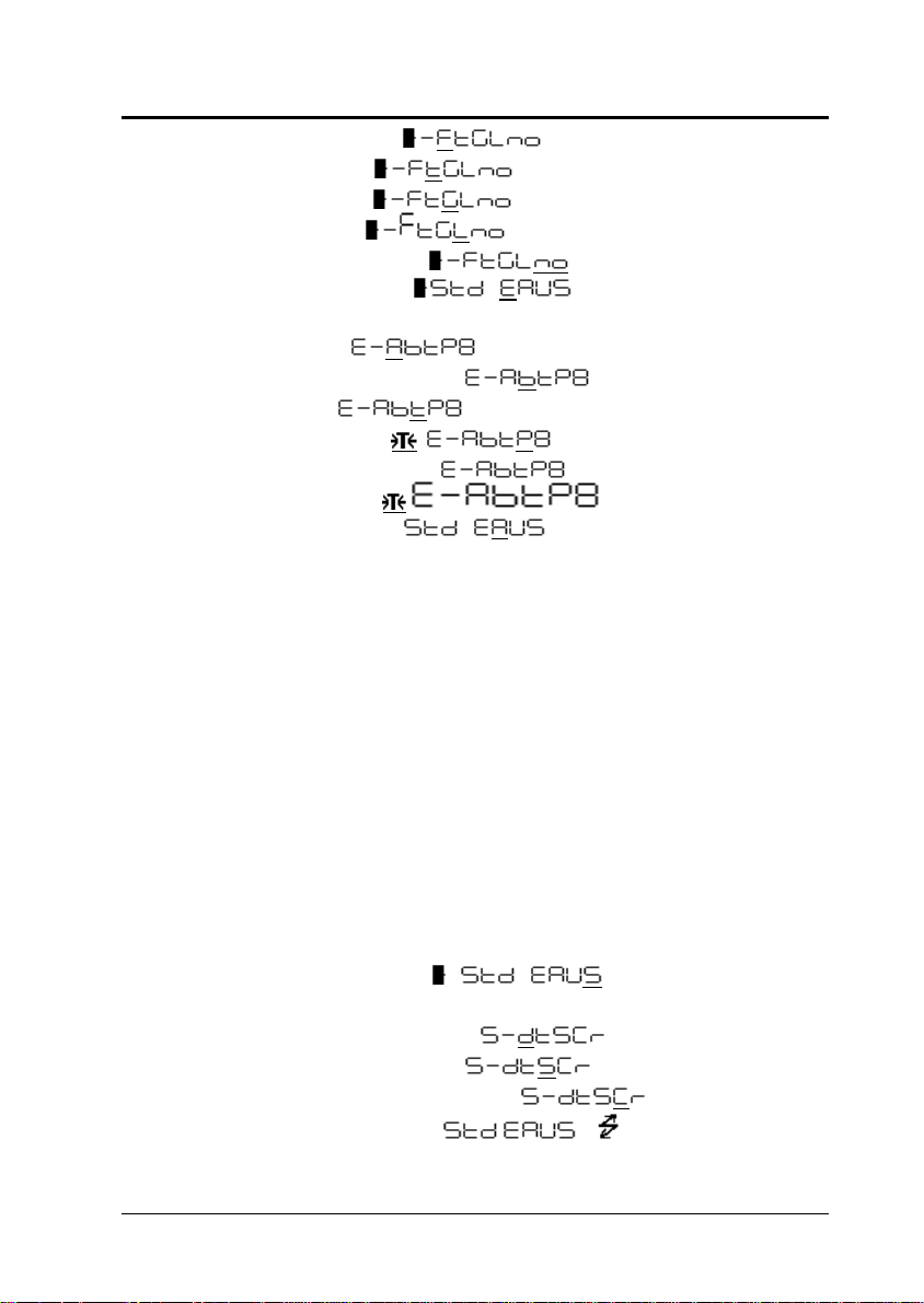
2.6.2 Full Scale Mode ..........................................37
2.6.3 Target Mode ................................................37
2.6.4 Group Mode .................................................37
2.6.5 Level Mode ..................................................38
2.6.6 No Graphic Display .....................................38
2.7 Environment Menu : ............................38
2.7.1 Overview......................................................................................38
2.7.2 Averaging
........................................................39
2.7.3 Stability Detection Band ................................40
2.7.4 Tracking ...........................................................40
2.7.5 Pretaring Value ........................................40
2.7.6 Whole Lighting Mode .....................................41
2.7.7 Taring/Printing ..............................42
2.8 Application Menu : ................................42
2.8.1 Overview......................................................................................42
2.8.2 Zero Range .................................................................................43
2.8.3 Auto Zero.....................................................................................43
2.8.4 Auto Print .....................................................................................44
2.8.5 Peak Hold....................................................................................45
2.8.6 Interval Timer ..............................................................................46
2.8.7 Auto-Memory and Zeroing .......................................................47
2.8.8 Animal Weighing ........................................................................48
2.9 Unit Registration Menu and Unit Change .....................49
2.9.1 Unit Registration Menu..............................................................49
2.9.2 % Conversion .............................................................................50
2.9.3 Piece Counting ...........................................................................50
2.9.4 Solid Specific Gravity Measurement.......................................51
2.9.5 Liquid Specific Gravity Measurement.....................................53
2.10 System Setting Menu
: .......................54
2.10.1 Date for the Built-in Clock..........................................................54
2.10.2 Time for the Built-in Clock
............................55
2.10.3 Display During Standby ................................55
2.10.4 Measurement Control System ....................56
2.11 Communication Menu ( flashing).....56
2.11.1 Overview......................................................................................56
Reflex HC Series
7
Page 8
2.11.2 Handshaking - ............................................ 57
2.11.3 Format ....................................................... 57
2.11.4 Communication Speed .......................... 58
2.11.5 Parity / Bit Length - ....................................... 58
2.11.6 Stop Bit ........................................................ 58
2.11.7 Delimiter ....................................................58
3 Connecting Peripheral Instruments..................................59
3.1 Electronic Printer ...........................................................59
3.2 Personal Computer - RS-232C - ...................................59
3.2.1 Connecting the Cable ............................................................... 59
3.2.2 Data Format................................................................................ 60
3.2.3 Using Command Codes .......................................................... 61
3.2.4 Windows Direct Function.......................................................... 67
3.2.5 Multi-Connection Mode............................................................. 70
3.3 Foot Switches................................................................73
3.4 Hook for Below-Balance Weighing................................73
4 APPENDIX............................................................................75
4.1 Table of Unit Conversion Constants .............................75
4.2 Specifications for the RS-232C/AUX Connector...........76
4.3 Error Display List ...........................................................77
4.3.1 General Display.......................................................................... 77
4.3.2 Error Display ...............................................................................77
8
Reflex HC Series
Page 9

INTRODUCTION
Thank you for purchasing this medium-sized electronic
balance, the Avery Weigh-Tronix Reflex HC series.
In addition to its ability to make rapid mass measurements, the
Reflex HC series is also well-equipped with a four-mode
analog display, clock function, various application
measurement functions and a unit conversion function.
Furthermore, it is a high performance, multi-functional balance
which can be used in a great variety of applications when
connected to peripherals. Before using the balance read this
instruction manual carefully to ensure long and fruitful use of
the Reflex HC series.
Reflex HC Series
9
Page 10
1 Basic Operation
10
1 Basic Operation
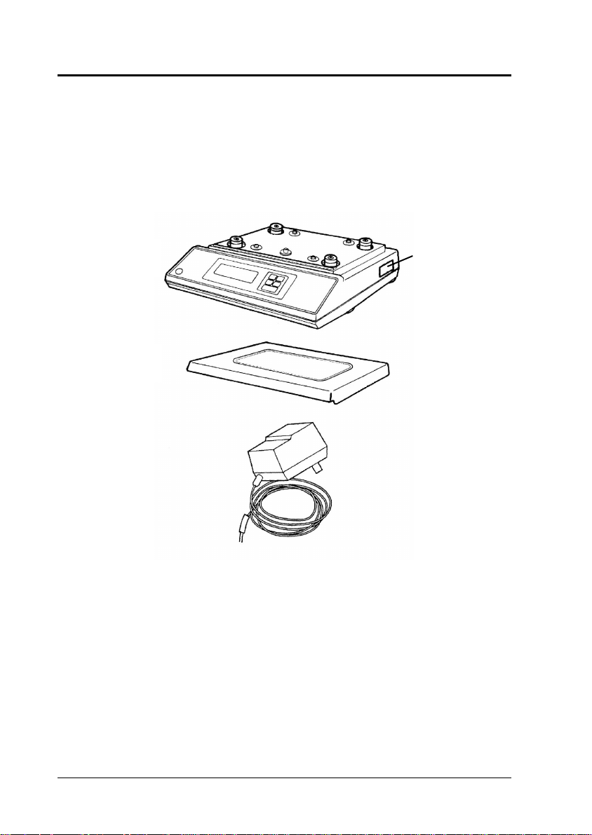
1.1 Balance Components
[ Name ]
Balance unit
Pan
AC adaptor
[ Appearance ]
[ Notes ]
The serial
number of the
balance is stated
on this
nameplate
Reflex HC Series
Page 11
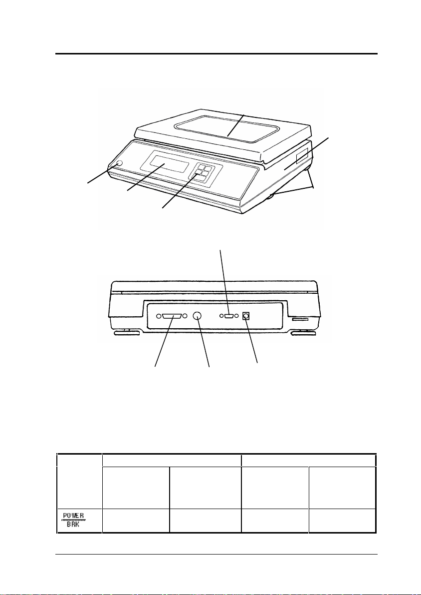
C
Pan
1 Basic Operation
Balance unit
Level
Display
panel
Key
Level screws
switch
KEY Connector
RS-232C
Connector
DATA I/O
DCIN
Connector
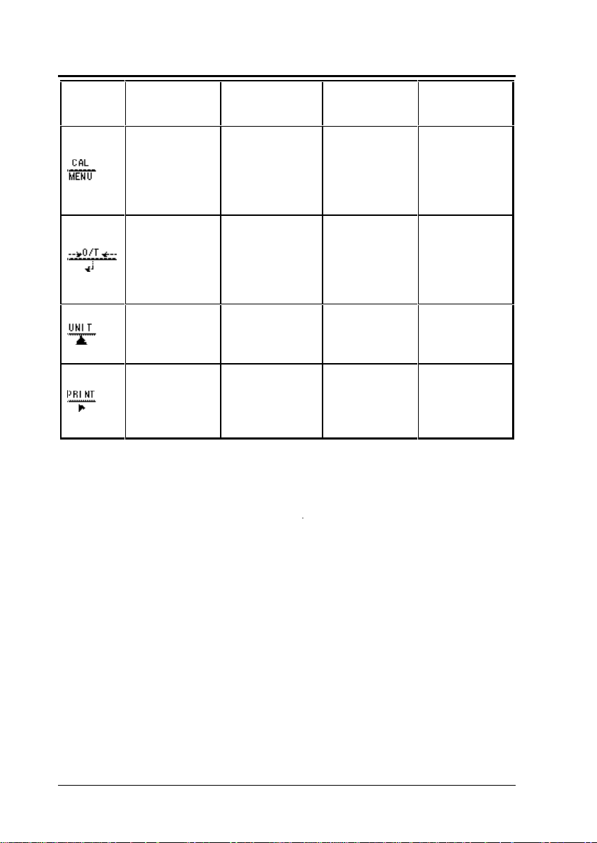
1.1.1 Operations of the Keys on the Main Unit
The functions of the keys found on the front of the balance are
described in the table below.
During Weighing During Menu Selection
Key
Pressing
Once and
Releasing
Switches
between the
Pressing and
Holding for
About 3
Seconds
Exits the
Application
Pressing
Once and
Releasing
Returns to
the previous
Pressing and
Holding for
About 3
Seconds
Returns to the
mass display.
(*1)
Reflex HC Series
11
Page 12
1 Basic Operation
operation and
standby
modes.
Enters span
calibration or
menu
selection.
Tares the
balance.
(Displays
zero.)
(*3)
Changes the
selected unit.
(*4)
Sends the
displayed
value to a
peripheral
device.
(*2)
Measurement
function.
Displays the
last Menu Map
item that was
set.
(Last menu
recall)
Displays the
Pretare value.
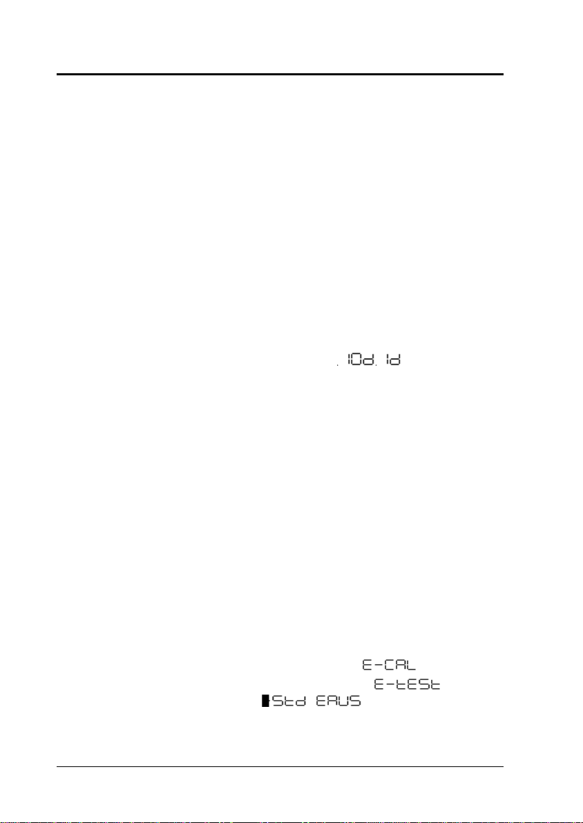
Switches
between the 1d
and 10d
display.
Sends the date
and time to a
peripheral
device.
(*5)
menu.
Moves to the
next Menu
Map item.
Selects and
sets the
currently
displayed
Menu Map
item.
Increases the
numeric value
of the flashing
digit by 1.
Moves to the
next digit
during
numeric value
entry.
Displays the
last Menu
Map item that
was set.
(Last menu
recall)
No operation.
No operation.
No operation.
*1 Refer to Section 2. “MENU SELECTION.”
*2 This key is used to set values when percent (%), number
(PCS), solid specific gravity (
d), or liquid specific gravity (d)
units are displayed.
*3 When a Pretare value is set, zero is not displayed and the [-
Pretare value] is displayed.
*4 Units other than “kg” must be registered and set before they
can be used for measurement. Kilogram (kg) is the only unit
registered before shipment. To register other units, refer to
Section 2.10. “REGISTRATION, RELEASE, AND SELECTION
OF MEASUREMENT UNITS”.
*5 When the unit is set to 10d, the resolution of the minimum
display is decreased by one decimal place.
12
Reflex HC Series
Page 13
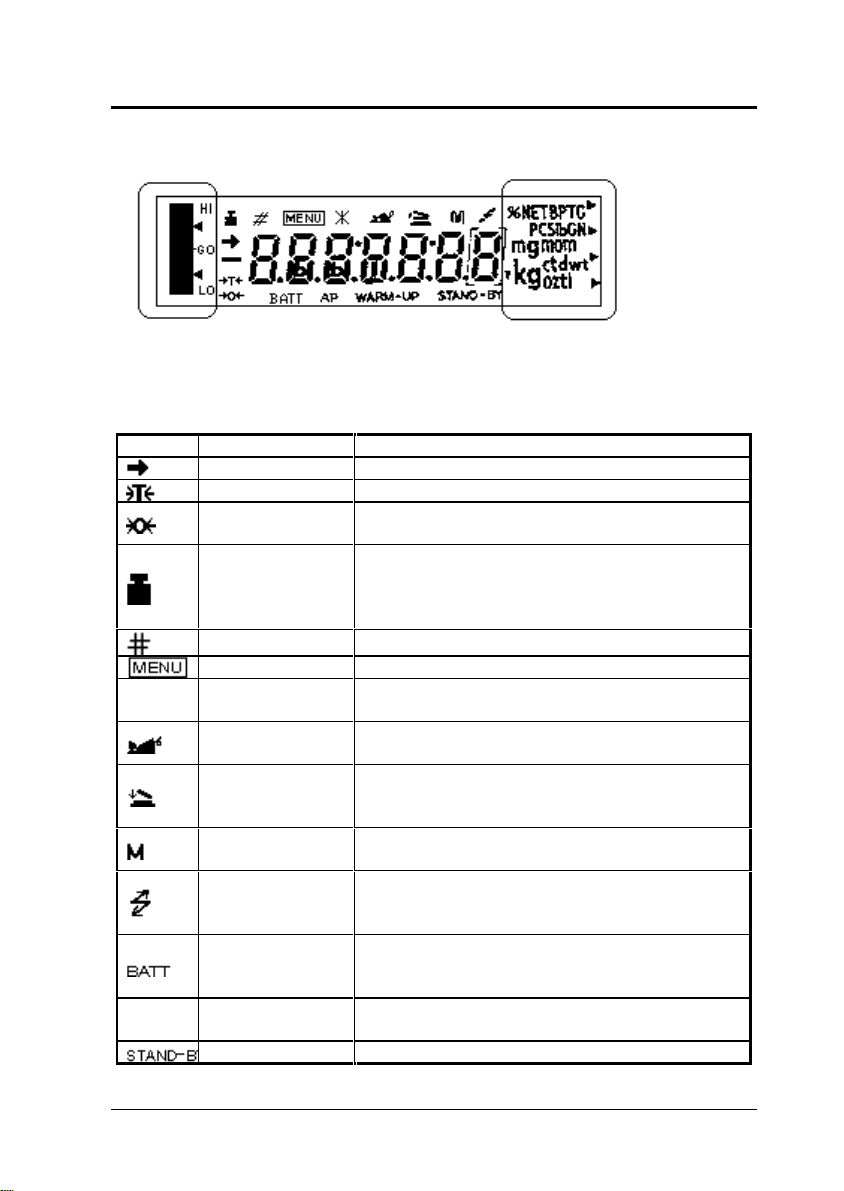
1.1.2 Symbol Display
Graphic display Unit display
An example of “whole lighting” display.
Display Name Description
Stability symbol Indicates that the balance is stable. (*1)
Tare symbol Indicates that a Pretare value has been set.
Zero symbol Indicates that Auto Zero is ON for the
Application Measurement function.
Weight symbol Flashes when span calibration is necessary.
This symbol continues to flash until either a
manual or automatic span calibration has been
made.
Number symbol Indicates numeric value entry.
Menu symbol Indicates that the menu lock is on.
*
AP
Asterisk Indicates that the displayed numeric value is
not a mass value.
Animal symbol Illuminates when Animal Weighing is ON for
the Application Measurement function.
Auto-Memory &
Zeroing symbol
Memory symbol Indicates that Net Total Weighing is ON for the
Communication
symbol
Battery symbol When the balance is operated with the optional
Auto Print
symbol
Stand-by symbol Illuminates when the balance power is in the
Illuminates when Auto-Memory and Zeroing
are ON for the Application Measurement
function.
Application Measurement function.
Illuminates during communication to external
equipment through the RS-232C or DATA I/O
connector.
battery pack, this symbol illuminates to indicate
that the battery voltage has dropped.
Indicates that Auto Print is ON for the
Application Measurement function.
1 Basic Operation
Reflex HC Series
13
Page 14
1 Basic Operation
standby mode.
This symbol also illuminates when the
Application Measurement function has entered
the standby mode.
Inverse triangle
•
symbol
Illuminates when the solid specific gravity unit
is used. This symbol is also used as a
substitute for the decimal point.
*1 Stability symbol
The displayed value may change while the stability symbol
remains illuminated if the load is changing slowly or if the
stability detection band has been set to a large value.
1.2 Installation
1.2.1 Choosing the Installation Site
(1) Power supply
CAUTION
• Select an installation site that is near a power source to
ensure that the attached AC adapter is used properly.
• Verify that the supply power voltage conforms to that
indicated on the AC adapter.
14
(2) Installation site
CAUTION
Choose an installation site where the balance will be
protected from the following:
• corrosive or flammable gasses.
• dust, wind, vibration, electromagnetic waves, or
magnetic fields.
• direct sunlight.
• extreme temperature or humidity.
• rain or the possibility of being splashed with water.
Large capacity balances should be installed on a sturdy
floor and table that can withstand the total load of the
balance AND object to be weighed.
Reflex HC Series
Page 15
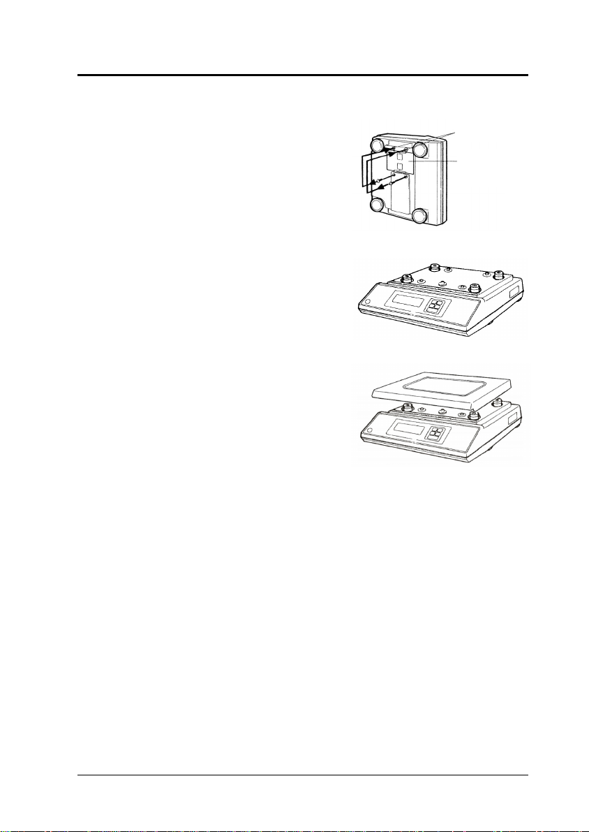
1.2.2 Balance Installation
1 Basic Operation
(1) Put the balance onto its
side and unscrew the 2
transportation screws in
accordance with the
instruction label on the
bottom of the balance.
Screw these into the
“Release” hole.
(2) Place the balance unit as
shown in the diagram on
the right. If intending to fit
the vinyl cover, fix it at this
stage of the procedure.
Refer to “Fitting the Vinyl
Cover”, mentioned later.
(3) Place the pan on the
balance.
(4) Adjust the level of the
balance.
Note: Turn the level
screws to adjust it so that the air bubble in the level
rests inside the red circle. Check that the balance is
steady when adjustment is complete.
Release hole
Instruction label
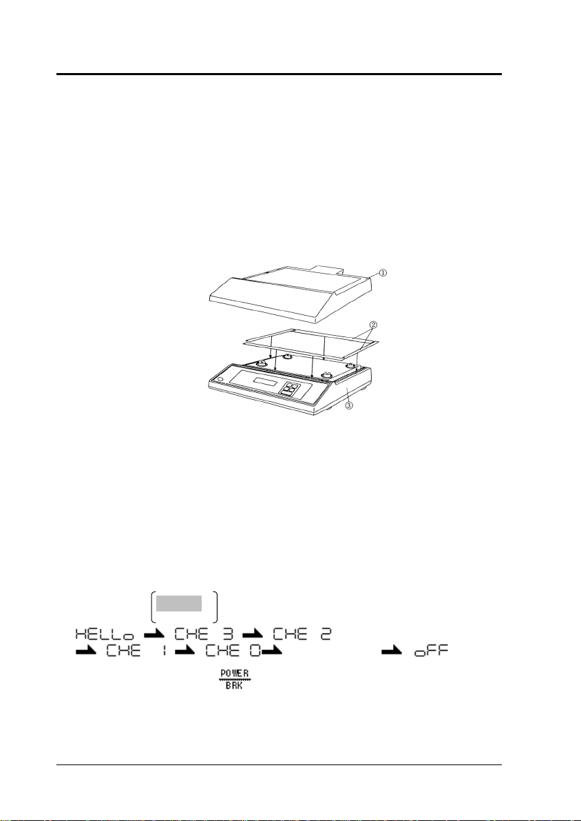
Fitting the Vinyl Cover
When using the balance in a location where it is likely to get
dirty, refer to the diagram below and fit the vinyl cover by
following the procedure below. Remove the pan first if fitting
the vinyl cover after the balance has been assembled.
Reflex HC Series
Note: Adjusting the level can be done with ease if all 4
level screws are at first grounded equally. Next, adjust
the front and the back using the 2 front feet, and then
adjust left and right using either of the 2 feet on the left
and right.
15
Page 16
1 Basic Operation
16
(1) Cut the supplied tape (2) and stick it onto the 4 points
on the case (3) (refer to the diagram below).
(2) Fix the vinyl cover (1) onto the double-sided tape (2),
ensuring that there are no creases.
(3) Fit the pan.
(4) Place a weight onto the pan which is close to the
weighing capacity to check that the pan and vinyl cover
are not touching. Accurate measurements cannot be
made if there is contact between the two items. If this is
the case, re-fit the vinyl cover.
Note: The vinyl cover (1) is folded up when it is in the packaging.
1.3 Turning the Power ON
(1) Insert the plug of the AC adapter into the DC IN
connector on the rear of the balance, then insert the AC
adapter into the power source.
(2) The balance self-check is activated and the following
messages are displayed in the order indicated.
Ver. No.
•• • • • •
•• • • • • Whole lighting
(3) Press the
then the display changes to indicate the kilogram-
display.
key. The whole display illuminates and
Reflex HC Series
Page 17
Note: If ENVIRONMENT menu 37
been selected, the display stops in the whole lighting
state. In this case, press the
lighting to change the display to the kilogram-display.
1.4 Adjusting the Built-in Clock
The Reflex HC series of balances have a built-in battery driven
clock. After unpacking and installing the balance, adjust this
clock to the appropriate date and time.
See Section 2.10.1 Date for the Built-in Clock
See Section 2.10.2 Time for the Built-in Clock
1.5 Span Calibration
It is necessary to calibrate the balance after it is moved, or
when the ambient temperature has changed.
Verify that the balance is stable before performing the span
calibration. To achieve a very stable state, ensure that the
balance has been turned on for at least one hour, that the
temperature is constant, that there are no breezes or
vibrations and that the balance is in an area isolated from the
normal traffic flow.
1 Basic Operation
has
key during whole
Refer to Section 2.5.2 “Span Calibration Using the External
Weights” for more information on the Span Calibration
procedure.
1.6 Weighing
(1) Place the weigh vessel (tare) on the pan.
(2) Press the
Note: If a Pretare value is set, the
illuminated and zeroing of the display does not occur.
(3) Place the object to be weighed on the pan, and read the
displayed value after the stability symbol is displayed.
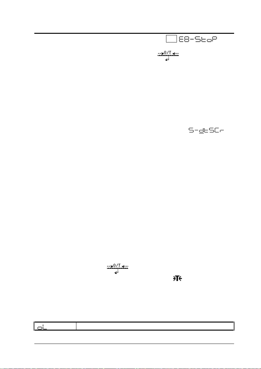
Errors Displayed During Weighing
Reflex HC Series
key to zero the display.
Overload: Weighing capacity has been exceeded.
symbol is
17
Page 18
1 Basic Operation
18
Negative Overload: The load on the balalnce is too
light.
The pan is not adjusted properly.
Display Overload: This display appears if the mass
display exceeds 7 digits due to the choice of unit.
May appear after the
solid specific gravity (
units are used.
key is pressed while the
•d)or liquid specific gravity (d)
1.6.1 Changing the Unit Display
Every time the key is pressed, the unit display changes
sequentially among those registered in the UNIT
REGISTRATION menu.
Note: Before a unit can be displayed it must be registered in
the UNIT REGISTRATION menu. Refer to “2.10 Unit
Registration Menu and Unit Change” for information on how to
register units.
The unit is displayed sequentially according to the order of the
UNIT REGISTRATION menu.
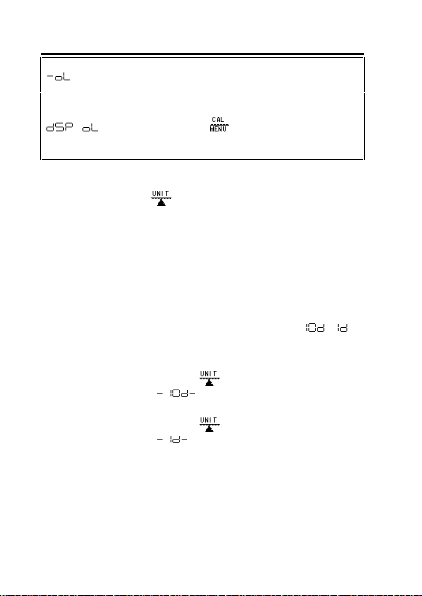
1.6.2 Changing the Minimum Display Digit• •
It is possible to decrease the resolution of the minimum
balance display by one decimal place if necessary.
(1) Press and hold the
seconds.
decreased by one decimal place.
key for approximately three
is displayed and the display is
(2) Press and hold the
seconds.
the original number of decimal places.
is displayed and the display returns to
key for approximately three
1.7 Maintaining and Transporting the Balance
1.7.1 Cleaning the Balance
Use a soft damp cloth containing a pH neutral detergent to
clean the balance.
Reflex HC Series
Page 19

Avoid using organic solvents, chemicals, or dusting sprays as
they may damage the coatings of the balance or the display
panel.
Attach the in-use balance cover (standard accessory) when
the balance is used in an environment where it is susceptible
to being soiled.
The pan can be removed and washed with water. Verify that
the pan is completely dry before replacing it on the balance.
1.7.2 Transporting the Balance
To carry the balance, hold the balance firmly with both hands.
To transport the balance, use the shipping carton used to
deliver the balance.
Before placing the balance into the shipping carton, verify that
the transportation screws at the bottom of the balance have
been tightened until they stop.
1 Basic Operation
Reflex HC Series
19
Page 20
2 Menu Item Selection
20
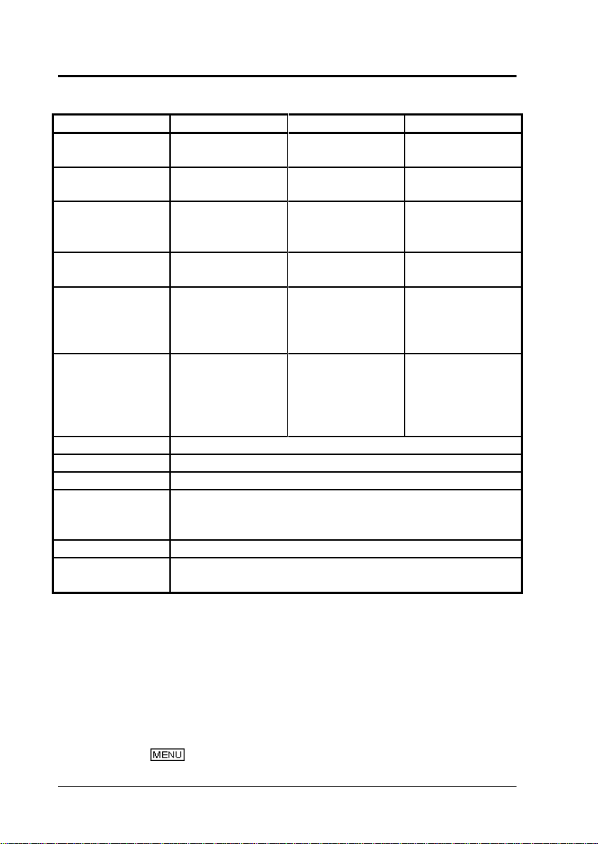
1.8 Specifications
Type HC12000 HC32000 HC52000
Weighing
Capacity (kg)
Minimum
Display (g)
Standard
Deviation
(
•)g
Linearity
±g
Range of the
External
Calibration
Weight (kg)
Temperature
coefficient of
sensitivity
Pan size (mm) Approx.345 W x 250 D
Dimensions Approx.360 W x 355 D x 125 H
Weight (kg) Approx 10.5kg
Operating
Temperature
Range
Power Supply AC adapter (AC110 V – 240 V)
I/O Connector for RS-232C
12 32 52
0.1 0.1 1
0.1 0.12 0.6
0.2 0.2 1
10 30 50
± 4ppm/°C ± 5ppm/°C
(Range of
temperature
compensation:
10 to 30°C)
5 - 40°C
for Electronic Printer
± 4ppm/°C
2 Menu Item Selection
2.1 Introduction
The HC series balance has many functions that can be
selected to meet the requirements of the user. Menu Item
selection is used to program these functions.
The
symbol is displayed during Menu Item selection.
Reflex HC Series
Page 21
Once the menu items have been set based on the installation
environment and weighing purpose, it is not necessary to
select the menu items each time the balance is used. Once
the contents of the menu are set, they are stored even if the
balance is turned OFF or if the power is disconnected.
2.2 Procedure of Menu Item Selection
The menu of the HC Series balance consists of four levels.
2 Menu Item Selection
(1) Press the
menu level.
( in the table below)
(2) Press the
move to the next menu level.
( in the table below)
(3) Press the
(4) Press and hold the
display.
(5) This instruction manual identifies each menu item by a
number. For example,
mode” is identified as [25].
(6)
Press the
to enter the associated menu.
Refer to Section 2.3 "Menu Map" or the attached
operation explanatory sheet.
Symbols in the : Display
(Calibration) = Enters the menu related to
(Graphic display) = Enters the menu related to
(Environment) = Enters the menu related to
key to cycle through the items within a
key to choose the current item or
key to move back one menu level.
key to return to the mass
, “Anti-Vibration
key when the following symbols are flashing
span calibration.
the graphic display, target
and check weighing.
the installation
Reflex HC Series
21
Page 22
2 Menu Item Selection
(Application) = Enters the menu related to
(Unit) = Enters the menu related to
(System) = Enters the menu related to
(Communication) = Enters the menu related to
The stability symbol in the
that
2.3 Menu Map
To enter the Menu Map:
Turn the balance on.
environment and general
operation of the balance.
applications and printing.
unit conversion.
the system (clock, reports,
and passwords).
communication with a
computer and software.
: display indicates
, , and are set.
22
Press the
(This menu CAN NOT be entered from %, PCS,
displays.)
The selected span calibration type is displayed. The possible
displays are:
Press the key again to display the first menu level: :
Press the key repeatedly to cycle through the items or
press the
Mass Weighing Display
: Selects the flashing item.
key during mass display.
• , and
#
key to select the flashing item.
# Performs selected standard span
calibration.
Reflex HC Series
Page 23

Moves to the next item
# Default settings
symbol flashes.
2 Menu Item Selection
Calibration Menu
Sets type of span calibration.
flashing Sets I-CAL. (Span
calibration using
the external weight) # [3]
flashing Sets I-TEST. (Calibration
check using the external
weight) [4]
go to next page
# Default settings
Reflex HC Series
23
Page 24
2 Menu Item Selection
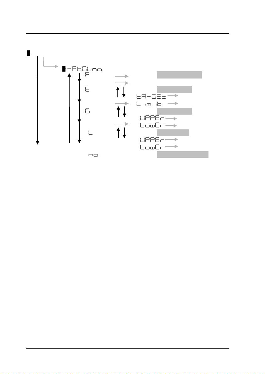
Graphic Display Menu
Graphic display flashing
go to next page
# Default settings
flashing Full Scale mode #
[11]
flashing Target mode [12]
Target value [13]
Limit value [14]
flashing Group mode [15]
Upper threshold [16]
Lower threshold [17]
flashing Level mode [18]
Upper threshold [19]
Lower threshold [20]
flashing No graphic display [21]
24
Reflex HC Series
Page 25

Environment Menu
flashing
go to next page
2 Menu Item Selection
flashing Averaging
Auto # [22]
Pouring [23]
Standard [24]
Anti-vibration [25]
Anti-wind [26]
flashing Stability detection
band
1 count # [27]
2 count [28]
4 count [29]
8 count [30]
16 count [31]
32 count [32]
64 count [33]
flashing Tracking
ON # [34]
OFF [35]
and flashing Pretare with all lighting
at start [36]
flashing
Stops. [37]
Does not stop #. [38]
flashing Taring/Print
Immediately # [39]
Waiting for
stabilization [40]
# Default settings
Reflex HC Series
25
Page 26

2 Menu Item Selection
Applications Menu
flashing
go to next page
symbol flashing Auto Zero On/Off
[41]
symbol flashing Auto Print
at + value [42]
at - value and
+ value [43]
at 0 and +
value [44]
at - value, 0,
and + value [45]
Continuous
Output [46]
Stability with
GO [47]
flashing : Zero Range [48]
flashing Peak Holding
On/Off [49]
flashing Interval Timer
PRINT
: : Time interval [50]
symbol flashing Memory
Weighing On/Off [51]
symbol flashing Auto-Memory and
Zeroing [52]
symbol flashing Animal Weighing
On/Off [53]
# Default Setting
26
Reflex HC Series
Page 27

Unit Registration Menu
f
flashing
go to next page
2 Menu Item Selection
g Gram (g) [54]
mg Miligram (mg) [55]
% Percent # (% [56]
pcs Number # (PC) [57]
ct Carat (CT) [58]
mom Momne (MO) [59]
G Immersion liq. density
Solid density(DS) [60]
d Reference wt. volume
Liquid density(DL)
[61]
Lb Pound [61a]
Oz Ounce [61b]
Ozt Troy Ounce
[61c]
Hong Kong’s tael
[61d]
Singapore tael
[61e]
Taiwanese tael [61f]
Malaysia tael [61g]
Chinese tael [61h]
dwt Pennyweight [61i]
GN Grain [61j]
m Mesghal
[61k]
b Bahts [61l]
t Tola
[61m]
During
measurement,
these items are
distinguished by
the position o
the symbol.
o Parts Pounds
Set the Multiplier for User
unit (US) [62]
Reflex HC Series
27
Page 28

2 Menu Item Selection
28
System Setting Menu
flashing
go to next page
flashing Current date setting [63]
flashing Current time setting [64]
flashing Display during standby
setting
Time [65]
Data [66]
No
display# [67]
flashing Report and control setting
CAL report
creating
Create [68]
Not create
# [69]
Balance ID
: [70]
PCAL
Password
: [71]
flashing
Menu reset
to default [72]
# Default settings
Reflex HC Series
Page 29

flashing
2 Menu Item Selection
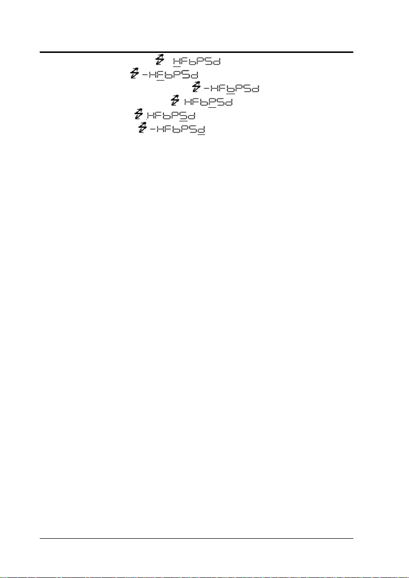
Communication Settings Menu
flashing Handshaking
No handshake [73]
Software [74]
Hardware [75]
Timer # [76]
flashing Data Format
EB type # [77]
Old EB type [78]
PR type [79]
IPS type [80]
flashing Baud Rate (Bits/sec)
300 bps [81]
600 bps [82]
1200 bps # [83]
2400 bps [84]
4800 bps [85]
9600 bps [86]
19200 bps [87]
38400 bps [88]
flashing Parity & bit length
None (8 bits) # [89]
Odd (7 bits) [90]
Even (7 bits) [91]
flashing Stop bit
1 bit # [92]
2 bits
flashing Delimiter
CR # [94]
LF [95]
CR+LF [96]
Reflex HC Series
WindowsDirect down [97]
WindowsDirect right [98]
29
Page 30

2 Menu Item Selection
30
# Default settings
Returns to flashing symbol.
Reflex HC Series
Page 31

2.4 General Menu Operations
2.4.1 Setting Numeric Values
Numeric values may be used to set the threshold of the
comparator with the Reflex HC series balances.
In a menu used to set numeric values,
illuminated and the digit to be input flashes.
• Press the key to increase the value of the
flashing digit by one.
•
Press the key to move the flashing digit one
place to the right.
• Press the key to store the displayed value in
the balance memory.
• is displayed when the value has been
successfully saved.
• is displayed when the balance failed to save the
value.
• Press the key to stop numeric entry. is
displayed briefly and the display returns to the menu,
one level up.
• … • •
2 Menu Item Selection
and are both
2.4.2 Setting a Decimal Point
• A decimal point is only used when setting units for
solid density weighing, liquid density weighing or when
setting the multiplier for the user defined unit. Set the
decimal point while setting numerical values as
follows.
• Press the key repeatedly until the last digit is
flashing. Press the
decimal point setting mode.
• The V\PERORUFXUUHQWGHFLPDOSRLQWIODVKHV
• Press the key to move the flashing decimal point
one digit at a time to the desired position.
Reflex HC Series
key once more to initiate
31
Page 32

2 Menu Item Selection
• Press the key to set the decimal point
position.
• is displayed briefly to indicate that the setting is
completed.
2.4.3 Menu Lock
The Reflex HC series of balances have a "Menu Lock"
function that locks the menu selections to avoid changes being
made by mistake.
The menu lock is toggled ON and OFF by pressing the
key during display that appears after power is supplied
to the balance.
is displayed when the menu is locked.
is displayed when the menu lock is turned off.
Menu lock is on. Menu lock is off.
Note: Access is denied and is displayed when the
user attempts to select a locked menu.
Use the following procedure to turn off the menu lock function
and restore access to the menus.
(1) Disconnect power from the balance and wait 10
seconds. Reconnect power to the balance.
(2) When
(3)
has been turned off.
is displayed, press the key.
is displayed to indicate that the menu lock
2.4.4 Last Menu Recall
This function is convenient when an application requires
frequent changes to a specific Menu Map item.
During mass display or menu selection, press and hold the
•
32
key for approximately three seconds. The last Menu Map
item that was changed or set is displayed.
Reflex HC Series
Page 33

2 Menu Item Selection
2.4.5 Returning to the Default Settings (menu reset)
The procedure below describes how to reset the menu and
return to the default settings.
Default settings are indicated with the # symbol in the Menu
Map. (
Select Menu Map item [72] to reset the menu.
Section 2.3 "Menu Map").
(1) In the mass display, press the
of : flashes.
the
(2) Press the key.
(3) The system setting menu is selected
(4) Press the
(5) Press the
means "?").
(6) Press the
(7)
completion.
(8) Press the
approximately 3 seconds) to return to the mass display.
key repeatedly until the
is flashing.
key to display (" "
key again.
is displayed to indicate menu reset
key several times (or hold it for
2.5 Calibration Execution Menu
2.5.1 Calibration
key repeatedly until
.
in
Calibration is required to accurately weigh items with an
electronic balance. Calibration should be performed:
y When the location of the balance is changed, even
y When the room temperature changes considerably.
y Periodically, according to the quality control plan of the
Terms used in this manual:
Reflex HC Series
within the same room.
user.
33
Page 34

2 Menu Item Selection
Span Calibration: Adjustment of the balance to specifications
using two weight values; zero and an
appropriate value for the balance capacity.
Calibration Check: Comparing the current calibration mass
reading to the calibration mass reading after
the last span calibration.
Factory Default Settings
Reflex HC series Calibration using the external weight.
(
The settings for the type of calibration can be changed with
menu selection.
Section 2.6.1 "Selecting Standard Calibration Type."
Note: The following displays may appear in the situations
listed.
When it takes too much time to stabilize the
balance.
When the zero point of the balance appears to
have changed greatly.
When the balance calibration appears to have
changed greatly or the wrong weight is loaded on the pan
during calibration.
In all of these situations, span calibration or calibration check
is not performed.
Refer to Section 4.4.2 “Error Display.
)
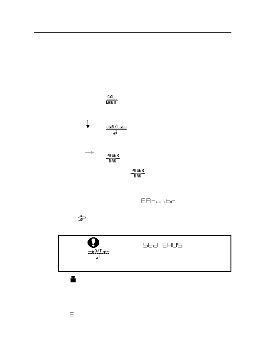
2.5.2 Span Calibration Using External Weights
(1) Verify that the balance is in mass display and unload the
sample from the pan.
(2) Press the
(3) (If
and select Menu Map item [3].)
Press the
The value of the correct calibration mass to be loaded is
displayed and flashes.
34
key once. is displayed.
is not displayed, return to mass display
key.
Reflex HC Series
Page 35

2 Menu Item Selection
Changing the Calibration Mass to be Used
Pressing the
Modify the value using the
the
(4) Load the indicated calibration weight and press
the
(5) Shortly, zero display flashes. Unload the weight from
the pan and press the
calibration.
key allows changes to the weight value.
key and key, then press
key. To interrupt modification, press the key.
key.
key.
is displayed briefly to indicate completion of span
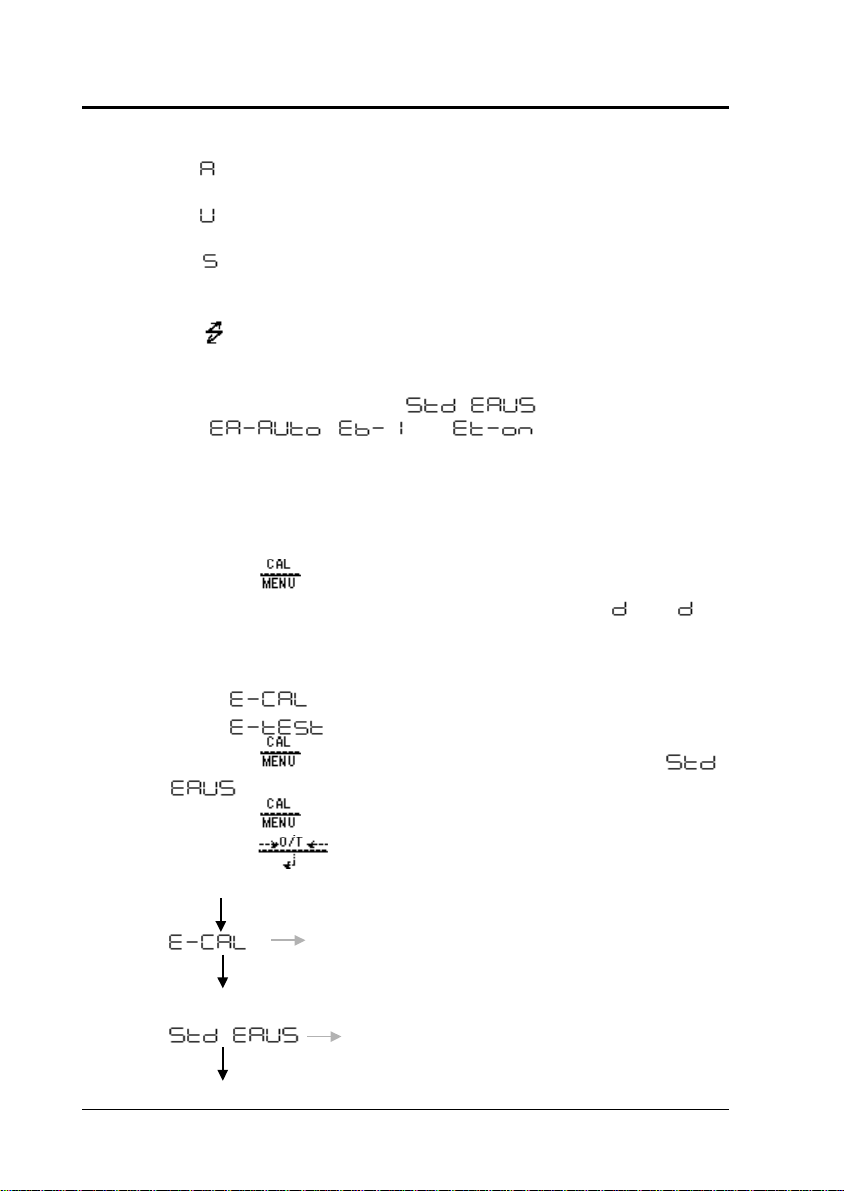
2.5.3 Calibration Check Using External Weights
(1) Verify that the balance is in mass display and unload the
sample from the pan.
(2) Press the
(3) (If
[4].)
key once to display .
is not displayed, select Menu Map item
(4) Press the
(5) The value of the correct calibration mass to be loaded is
displayed and flashes.
Changing the Calibration Mass to be Used
Pressing the
the value using the
key. To interrupt modification, press the key.
Reflex HC Series
key allows changes to the weight value. Modify
key.
key and key, then press the
35
Page 36

2 Menu Item Selection
36
(1) Load the indicated calibration mass and press the
(2) The zero display flashes.
(3) Unload the weight from the pan and press the
key.
key.
(4) The display changes to the
a numeric value)
(5) To change the
(6) Press the
zero. Pressing the
does not change this value to zero.
Note: Changing the
performing span calibration.
value to zero, press the key.
key to avoid changing the value to
value to zero is equivalent to
xxx display. (xxx indicates
key interrupts calibration and
2.6 Graphic Display Menu :
2.6.1 Overview
The Reflex HC series balance has a bar graph located on the
left side of the display. This graph can be conveniently used
for liquid weighing and pass or failure judgment (comparator
function) of the sample.
The graphic display functions include the Full Scale mode,
Target mode, Group mode, Level mode, and no graphic
display mode.
Note: Target, limit, upper, and lower values are set as numeric
values only. Set the correct numeric value for the unit that will
be used for weighing.
y In weighing mode, changing the displayed unit does
NOT change the target, limit, upper, or lower numeric
values. For example, when the upper limit has been set
at 10g, switching the unit from “g” to “kg” does not
change the limit to 10kg. It will be 0.01kg.
y The decimal point is invisible in the value setting display.
Determine its position based on the resolution of the
balance. For example, if the balance’s minimum display
Reflex HC Series
Page 37

is 0.01g, 150g must be set by inputting “15000” in the
display.
y Numeric values are memorized independently for each
graphic display mode.
y The graphic display mode can be selected without
setting numeric values.
2.6.2 Full Scale Mode
The relative amount of the load on the pan is displayed in the
bar graph. This feature helps to prevent errors due to OL
(overload) status.
Use Menu Map item [11] to select the Full Scale mode.
A bar displayed in the lower areas of the scale indicates that
the load on the pan is small.
A bar displayed in the upper areas of the scale indicates that
the load on the pan is close to the weighing capacity.
2.6.3 Target Mode
Target mode is useful for filling applications or for quality check
by weight.
The
amount in the unit that is used for weighing. The
value is the numeric amount above or below the target value
that is acceptable.
This mode is useful for constant amount weighing of liquid or
judgment of excess and shortage.
Menu Map item [12] selects the Target mode.
Menu Map item [13] sets the
Menu Map item [14] sets the
value is the numeric value that is the desired
2 Menu Item Selection
value, which
corresponds to the center line of the
graphic display.
value, which
corresponds to the distance between
the center line and upper or lower
triangles.
2.6.4 Group Mode
This is the best mode to determine pass or failure judgment
based on the sample weight.
Reflex HC Series
37
Page 38

2 Menu Item Selection
38
Menu Map item [15] selects the Group mode.
Menu Map item [16] sets the upper threshold value, which
corresponds to the upper triangle.
Menu Map item [17] sets the lower threshold value, which
corresponds to the lower triangle.
Note: Determination as follows:
Display
< Sample weight HI
< Sample weight < GO
Sample weight < LO
2.6.5 Level Mode
Use this mode for classification based on the sample weight.
The display looks like a bar graph, but also includes a
comparator function.
Menu Map item [18] selects the Level mode.
Menu Map item [19] sets the upper threshold value, which
corresponds to the upper triangle.
Menu Map item [20] sets the lower threshold value, which
corresponds to the lower triangle.
Note: Determination as follows:
Display
< Sample weight HI
< Sample weight < GO
Sample weight < LO
2.6.6 No Graphic Display
Menu Map item [21] turns off the graphic display.
2.7 Environment Menu :
2.7.1 Overview
Settings on the balance can be changed to compensate for
the installation environment such as the degree of vibration
etc. or for the purpose of weighing a solid, liquid or powder.
Reflex HC Series
Page 39

2.7.2 Averaging
It is possible to match the stability of the display and the
degree of response with the requirements of specific
applications.
2 Menu Item Selection
Menu Map item [22]
AUTOmatic)
The balance automatically performs optimum averaging
dynamically while observing the load data. This is the
recommended setting and should be used unless special
circumstances exist.
Menu Map item [23]
POURing)
This mode is only suitable for constant volume weighing of
liquids etc. This mode is very sensitive to wind and vibration.
Menu Map item [24]
STaNDard)
This mode is suitable for weighing in a normal environment.
Averaging is fixed and does not change dynamically as in
.
Menu Map item [25]
VIBRation)
Use this mode when the balance is used in a location where
there are large vibrations and the display fluctuates in the
mode.
Response time is deteriorated by small mass amount
changes.
Menu Map item [26]
(Environment/Averaging-
(Environment/Averaging-
(Environment/Averaging-
(Environment/Averaging-
(Environment/Averaging-WIND)
Use this mode when the balance is used in a location where it
is exposed to airflow that causes the display to fluctuate in the
Response time deteriorates further than
weighing is comparatively stabilized.
Reflex HC Series
mode.
, but
39
Page 40

2 Menu Item Selection
40
Note: If weighing cannot be performed efficiently even with
, change the installation site of the balance or
use the deluxe windbreak or large pan windbreak.
2.7.3 Stability Detection Band
Menu items [27] to [33] are used to determine the conditions
for indicating balance stability.
(Environment/Band-1):
When the display has remained constant (within one display
count), the balance is regarded as stable and the stability
symbol illuminates. Stability detection band settings can be
selected from
to .
Note: Use
function is used and it is therefore required that the sensitivity
to vibration be reduced to allow the balance to be regarded as
stable and print the measurement value.
The balance may not operate properly if these settings are
selected under normal use conditions and environment.
to only when the Auto Print
2.7.4 Tracking
Tracking is the function that will maintain the current displayed
value as long as possible.
Menu Map item [34]
Menu Map item [35]
Zero Tracking Function
When the display is zero,
keep the zero display as long as possible. "Zero tracking" automatically
cancels small zero drift.
It is recommended to set to
change such as in the process of drop addition or liquid evaporation.
menu functions as "zero tracking" to
when measuring slight mass
Turns ON this function.
Turns OFF this function.
2.7.5 Pretaring Value
This function is used to weigh the mass of a sample packed in
a container such as a bottle or bag without opening the
container. Pretare function should be used only if the mass of
the containers does not vary from sample to sample. Instead
of zero the pretare value is displayed (as a negative value)
Reflex HC Series
Page 41

2 Menu Item Selection
when the key is pressed. The pretare value is then
subtracted from the load on the balance pan to determine the
weight of the sample.
(1) Menu Map item [36] opens the Pretare setting screen.
(2) Set the Pretare value using the
and press the
Pretare Value
Cancel the Pretare value by setting the value to zero.
When a Pretare value other than zero has been set,
illuminates.
The Pretare value is set using the "kg" unit. The maximum
value is dependant on the weighing capacity of the balance.
Check the Pretare value by pressing and holding the
key for approximately 3 seconds during weighing.
2.7.6 Whole Lighting Mode
Press the key to switch from the standby mode to the
mass display. The entire display is illuminated. This function
sets whether the display automatically proceeds to mass
display or waits for a
has been set to
because the display remains illuminated.
Menu Map item [37]
key and key,
key.
key command. When the mode
, it is easier to check the display
Display stops at whole lighting. Press the key to
proceed to the mass display.
Menu Map item [38]
After the whole lighting display has appeared for
approximately 0.5 sec, the display automatically proceeds to
the mass display.
Reflex HC Series
41
Page 42

2 Menu Item Selection
2.7.7 Taring/Printing
Determine if the balance should wait for stability before
printing when the
point when the
When the Application Measurement function is selected, the
key does not wait for stability.
Menu Map item [39]
Print and tare operate without waiting for stabilization.
Menu Map item [40]
Print and tare operate after the stability symbol illuminates.
Note: When the balance is in the
waiting for stability to be determined, ---- is displayed when the
key is pressed.
Press the
executed after the
Once the
and symbol has illuminated and the balance is stable. Data is
output only after the stability symbol is lit.
key to disable this function. Taring is not
key is pressed, data is not output until the
key is pressed or displaying the zero
key is pressed.
key is pressed.
2.8 Application Menu :
2.8.1 Overview
mode and
42
The Application Measurement function is the generic name of
the functions used to perform measurement work using the
balance in more efficient ways. Only one Application
Measurement function can be used at a time. When the power
is turned ON, the balance will begin in the function mode that
was last set.
Cancellation of Application Measurement
To cancel the Application Measurement, press the
while in the mass display and hold it until
displayed.
is
Reflex HC Series
key
Page 43

2 Menu Item Selection
To use the Application Measurement function that was just
canceled, use the last menu recall function by pressing and
holding the
Using the Application Measurement Function with a
Select the Application Measurement function while in the mass
display, and select the unit of weighing with the
Because the operation of the
normal mass display, the Application Measurement function
cannot be selected while %, PCS, or specific gravity units are
displayed.
2.8.2 Zero Range
The "Zero Range" value is used in the Application
Measurement function as a reference to identify whether the
sample is loaded.
For example, if the display is within the Zero Range, the
balance determines that a sample is not loaded. If the display
is more than five times the Zero Range it determines that a
sample is loaded. Application Measurement functions which
involves judgment of whether a sample is loaded or not work
in accordance with the Zero Range setting.
In Menu Map item [48], the "Zero Range" value is set using
the number of counts displayed in kilogram-display.
The setting range is 01 to 99 with 01 being the default value.
Even when weighing will be done in another unit, Zero Range
setting is made by only gram value.
Note: When a Pretare value is set, the value to determine that
there is "no load" becomes
"- Pretare ± Zero Range" during mass display. For example,
the Zero Range function works as expected when attempting
to weigh and Auto Print the mass of a bottled sample during
mass display.
key for 3 seconds in the mass display.
Unit Other Than "kg"
key.
differs from the one in
2.8.3 Auto Zero
Select Menu Map item [41].
Reflex HC Series
43
Page 44

2 Menu Item Selection
When the displayed value is within the Zero Range and the
stability symbol has illuminated, zeroing occurs automatically.
The
function is active.
Other keys function as expected with the Auto Zero function
activated.
symbol appears in the display when the Auto Zero
2.8.4 Auto Print
Auto Print function allows output of the data automatically
without pressing the
is illuminated when the Auto Print function is activated.
Six types of Auto Print are possible.
Menu Map item [42]
Load the sample when the value displayed is within the Zero
Range. When the stability symbol has illuminated and the
positive displayed value is more than 5 times the Zero Range,
data is automatically output.
The next data output is not performed unless the display has
returned to a value within the Zero Range by unloading the
sample or pressing the
Menu Map item [43]
Load or unload the sample when the displayed value is within
the Zero Range. When the stability symbol has illuminated and
the displayed positive or negative value is more than 5 times
the Zero Range, data is automatically output.
The next data output is not performed unless the display has
returned to a value within the Zero Range by unloading the
sample or pressing the
Menu Map item [44]
Load the sample when the value displayed is within the Zero
Range. When the stability symbol has illuminated and the
positive displayed value is more than 5 times the Zero Range,
data is automatically output.
key for each sample. The symbol
(on positive load)
key.
(on positive or negative load)
key.
(on positive load and on zero)
44
Unload the sample or press the
displayed value is within the Zero Range and the stability
symbol has illuminated, data is output again.
Menu Map item [45]
and on zero)
(on positive or negative load
key. When the
Reflex HC Series
Page 45

2 Menu Item Selection
Load the sample when the value displayed is within the Zero
Range. When the stability symbol has illuminated and the
displayed positive or negative value is more than 5 times the
Zero Range, data is automatically output.
Unload the sample or press the
displayed value is within the Zero Range and the stability
symbol ha illuminated, data is output again.
Menu Map item [46]
By pressing the
are lit, the
the displayed data is continuously output.
Continuous output stops temporarily when the
pressed.
Note: During continuous output, the
remain lit. If the transfer speed of the data output is slow, the
display may flash. Increase the transfer speed as much as
possible and set the handshake to
Menu Map item [47]
When the graphic display is in Comparator mode (Group mode
or Level mode) and the stability symbol lights in the GO range,
the data is output once.
The next data output is executed after the displayed value is
within the Zero Range.
2.8.5 Peak Hold
Menu Map item [49] measures the displayed peak value. The
symbol is illuminated when the Peak Hold function is
activated.
"Peak value" is the highest or lowest stable value displayed
after the display has changed beyond five times the Zero
Range.
key. When the
(on /continue)
key while the and symbols
symbol goes out, the symbol lights and
key is
symbol may appear to
.
(on / go)
(1) In the peak detection standby state with the
Reflex HC Series
and
symbols illuminated, press the key to
tare the display.
45
Page 46

2 Menu Item Selection
46
(2) Press the key.
The
detection starts.
symbol disappears and peak value
(3)
(4) Press the
Note: Press the
to initiate the power standby state.
Press the
the peak detection standby state.
Polarity of the peak value displayed is "polarity of the
displayed value of the first change by five times or more of
Zero Range from the display within Zero Range."
Usually the peak value is easily measured by setting to
the sample type, this setting may not always be successful.
and * are simultaneously displayed after the peak
value is detected, and the data is output. This display
will not change regardless of the load on the pan.
The balance returns to the peak detection standby state
in step 1).
key during detection of the peak to return to
[23]. Depending on the weighting conditions and
2.8.6 Interval Timer
Automatically outputs the displayed value at preset intervals.
The
symbol is illuminated when the Interval Timer is
activated.
(1) Using Menu Map item [50], set the output interval (00:01
= 1 sec to 99:59 = 99 minutes 59 seconds).
key.
key in the peak detection standby state
(2) In the interval timer standby state when the
symbols are both illuminated, press the
key.
The first data is output. Data is automatically output at
the set time intervals.
(3) To stop output, press the
The balance returns to the interval timer standby state in
step 1).
key.
Reflex HC Series
and
Page 47

Notes:
2 Menu Item Selection
y Use the
balance at any time.
y Pressing the
standby state causes the power supply standby state to
be initiated.
y To release the interval timer function, keep pressing the
key. This does not reset the interval timer function
to zero.
y Using the interval timer function to record data over a
long period may cause data error due to balance drift.
y Some instruments receiving the data may not operate
normally if the set time interval is short. To correct this,
set the time interval to a longer period. When the set
time interval is short and the instrument connected to
DATA I/O is unknown, it is recommended to set the
handshake to a setting other than
[76].
key to erase the tare or zero the
key while in the interval timer
2.8.7 Auto-Memory and Zeroing
Use Menu Map item [51].
(1) This menu is used to weigh a large number of individual
samples. The
illuminated when this function is active.
(Auto-Memory and Zeroing) symbol is
(2) Press the
(3) Load the first sample. Each time the stability symbol is
Reflex HC Series
Load the weighing vessel and press the
the Auto-Memory and Zeroing standby state (
symbols are lit).
Zeroing occurs.
key.
The
and Zeroing measurement starts.
lit and the display is a value five times or more the Zero
Range or the
output and zeroing occurs.
symbol disappears, and Auto-Memory
key is pressed, the displayed value is
key in
and
47
Page 48

2 Menu Item Selection
48
(4) For the next sample, additional weighing is performed
without pressing the
(5) Press the
The balance returns to the Auto-Memory and Zeroing
standby state and total mass on the pan without the tare
is displayed.
Press the
Notes:
y When the stability symbol is illuminated and the
displayed value is within the Zero Range, zeroing
occurs automatically.
y When the
is five times the Zero Range, zeroing occurs after data
output. (Manual loading)
y When the
Zeroing standby state, the power supply standby state is
initiated.
2.8.8 Animal Weighing
Set with Menu Map item [53].
This function is suitable for weighing animals.
symbol is illuminated when the Animal Weighing mode is
active.
key.
key.
key to print this value.
key is pressed and the displayed value
key is pressed in the Auto-Memory and
(animal)
(1) Load the weighing vessel and press the
Note: Data may be output when the weighing vessel is
loaded. This is not a malfunction.
(2) Load the sample (animal etc.) with a mass more than 50
times the Zero Range.
(3) When the weighed value is relatively stable, the value is
automatically output.
(4) Press the
(5) When the displayed value is stable and less than 10
times the Zero Range, automatic zeroing occurs.
Any residue remaining on the pan (excrement or fur) is
key or unload the sample.
Reflex HC Series
key.
Page 49

2 Menu Item Selection
automatically canceled and zeroing occurs. If zeroing
does not occur, increase the value of the Zero Range.
Notes:
y Standby state is not available in the Animal Weighing
mode.
y Press the
state.
y On the premise of weighing animated objects, the
stability detection band is automatically extended in the
Animal Weighing mode. Reproducibility of the
measurement data is slightly less than with other
modes.
y When the animal being weighed cannot be controlled
and Auto Print will not activate, press the
output the displayed value. Then unload the animal.
Even if the stability symbol lights before the animal is
removed, data is not printed again.
y By setting a larger stability detection band in the menu,
the stability symbol will light more readily.
y If the balance is slow to return to the zero point set a
larger Zero Range value.
key to initiate the power supply standby
2.9 Unit Registration Menu and Unit Change
•
2.9.1 Unit Registration Menu
Press the key in mass display to sequentially change the
registered units. It is possible to display units other than "kg"
with the Reflex HC series of balances. Before weighing, set
the display units to be used with the unit setting menu [54] to
[62]. (Unit kg, %, number (PCS) were set before shipment.)
Note:
y In the unit setting menu, the stability symbol is
illuminated to indicate the currently set units.
key to
y Set or release the unit by pressing the
Functional Units:
Reflex HC Series
key
when the unit is displayed.
49
Page 50

2 Menu Item Selection
50
Solid specific gravity unit (•d): Density of the liquid in which the
sample is immersed.
Liquid specific gravity unit (d): Volume of the reference weight
to be immersed in the sample.
unit ( Numeric value (multiplier)
multiplied by the gram (g) weight of the unit.
To register Functional Units, set the constant to something
other than 0. Setting the constant to 0 turns the function off.
For the unit names, refer to
2.9.2 % Conversion
(1) Set the % unit with Menu Map item [56].
The % unit is set before shipment.
Section 2.3 "Menu Map."
(2) Press the
until the % unit is displayed.
Setting the 100% reference
Press the key to tare the balance.
Load the reference sample that corresponds to the
100%value. This value must be equivalent to 100 counts or
more in the "kg" unit.
When the stability symbol illuminates, press the
is displayed briefly and the reference sample weight is
displayed as 100%.
Note: The numbers of digits displayed in the % unit and
rounding off of the minimum digit vary depending on the mass
value of the reference sample and the balance model. It is not
possible to obtain resolution greater than that in the “g” unit.
The weight of subsequent samples are displayed as a
percentage of the reference sample weight.
2.9.3 Piece Counting
(1) Register the PCS unit with Menu Map item [57].
(The PCS unit is registered before shipment.)
key several times in the mass display
key.
Reflex HC Series
Page 51

2 Menu Item Selection
(2) Press the key several times in the mass display
until the PCS unit is displayed.
(3) Load the container and press the
balance.
(4) Count exactly five pieces (or 10, 20, 50, 100, or 200
pieces) of sample to be measured and load them on the
pan.
(5) Press the
(6) Every time the
sequentially changes as
(7)
(Piece menu).
The default setting is
Press the
number of loaded pieces.
Example: If 50pcs. are loaded, press the
average weight per piece.
As sample is added or removed, the piece count (number of
pieces) is displayed.
Note: Repeat steps 3 through 6 above when the sample or
manufacturing lot is changed.
pcs pcs pcs ...
pcs is displayed. This determines the unit weight or
key.
key is pressed, the display
pcs.)
key when the display is equivalent to the
key to tare the
key when
Piece Count Menu Display Next Setting
In this example, when the
menu, display starts from
key is pressed in the next PCS
pcs.
2.9.4 Solid Specific Gravity Measurement
Solid specific gravity measurement refers to the measurement
of the sample (solid) weight in the air and in a liquid of known
density and the calculation of the sample density.
Reflex HC Series
51
Page 52

2 Menu Item Selection
The GV\PEROLVXVHGWRUHSUHVHQWWKHVROLGGHQVLW\XQLWLQ
this balance. The data output unit is DS.
(1) Set Menu Map item [60].
Note: Enter the value for the density (g/cm
3
) of the
liquid (water, alcohol etc.) in which the sample is
immersed.
(2) Attach the optional weighing hook to the bottom of the
balance, attach the hanging pan, and then immerse the
hanging pan in the tank filled with the liquid of known
density.
(3) Press the
(4) Press the
key until •d is displayed.
key.
(5) Load the sample on the balance pan or in the hanging
pan in air.
(6) After the stability symbol illuminates, press the
key.
may be displayed but does not indicate a
malfunction.
(7) Load the sample on the hanging pan immersed in the
liquid. The density of the sample is displayed.
(8) Repeat steps 4 through 7 for each additional sample.
Note:
y Up to four decimal places are displayed for specific
gravity. Since it may not be possible to stabilize the
balance using all 4 places, 1d/10d switching is possible.
y When loading the sample on the pan in the liquid,
ensure that the entire sample is immersed in the liquid.
52
y The balance does not re-zero when the
key is
pressed in this unit display.
y When the optional Specific Gravity kit is used, refer to
the Instructional Manual of the Specific Gravity kit for
the procedure.
y Return the balance to kg display mode first before
performing the next menu operation.
Reflex HC Series
Page 53

2 Menu Item Selection
2.9.5 Liquid Specific Gravity Measurement
Liquid specific gravity measurement refers to the
measurement of the weight of a reference solid of a known
volume in air and in the sample liquid.
The display unit for liquid specific gravity is "d." The data
output unit is DL.
(1) Set Menu Map item [61].
Note: Enter the value for the volume (cm
3
) of the
reference weight.
(2) Attach the optional weighing hook to the bottom of the
balance, attach the hanging pan, and then immerse the
hanging pan in a tank containing the sample liquid.
(3) Press the
(4) Press the
key until "d" is displayed.
key.
(5) Load the reference weight on the pan of the balance.
(6) After the stability symbol is illuminated, press the
key.
may be displayed but does not indicate a
malfunction.
(7) Load the reference weight on the hanging pan and
immerse it in the sample liquid. The specific gravity of
the sample liquid is displayed.
(8) Repeat steps 4 through 7 for each additional sample.
Reflex HC Series
53
Page 54

2 Menu Item Selection
Note:
y Up to four decimal places are displayed for specific
gravity. Since it may not be possible to stabilize the
balance using all 4 places, 1d/10d switching is possible.
y When loading the sample on the pan, immerse the
entire sample in the liquid.
y T release the
zero.
y When the optional Specific Gravity kit is used, refer to
the Instructional Manual of the Specific Gravity kit for
the procedure.
•d, d or units, set the value to
2.10 System Setting Menu :
The SYSTEM SETTING menu is used to set the items that
pertain to or are controlled by the balance.
2.10.1 Date for the Built-in Clock
(1) Select Menu Map item [63].
54
(2) Press the
(3) Set the last two figures of the year, month and day,
using the
key.
Example:
February 1st, 1997 Set as
February 29th, 2004 Set as . .
Note:
y The built-in clock corrects for the leap year
automatically.
y The moment the
above, seconds are set to zero. If the date is set after
setting the time, the second value will be incorrect. It is
important to set the date first and then the time, or to
correct the seconds value using the ± second correcting
function described later.
key.
and keys. Then press the
. .
key is pressed in step 2
Reflex HC Series
Page 55

2.10.2 Time for the Built-in Clock
(1) Select Menu Map item [64].
2 Menu Item Selection
(2) Press the
(3) 3) Use the
in the 24 hour system, then press the
Example: 1 o'clock 23 minutes in the afternoon Set as
:
Note: The moment the key is pressed is 00 seconds.
key.
key and keys to set the time
2.10.3 Display During Standby
Determine what is to be displayed during a power supply
standby.
Menu Map item [65]
standby.
Menu Map item [66]
standby.
Menu Map item [67]
standby.
key.
Displays the time during
Displays the date during
Displays nothing during
Reflex HC Series
55
Page 56

2 Menu Item Selection
56
The following functions are available when the time is
displayed during standby.
Seconds display function:
Convenient Functions of Time Display
Press the
seconds value.
key to enable the display/non-display of the
2.10.4 Measurement Control System
Items related to the calibration of the balance and those set by
the administrator are summarized in this menu.
Calibration Report
Turns the calibration report function on/off. Use this to
generate a calibration report as for GLP, GMP, or ISO9000. An
electronic printer (optional accessory) is required to print the
report.
Menu Map item [68]
created.
Menu Map item [69]
created.
Balance ID
Individual balances can be identified by the serial number on
the main body of the balance. The user can add a four-digit ID
number to the calibration report.
Set with Menu Map item [70]. Use a 4-digit number from
to .
Calibration report is
Calibration report is not
2.11 Communication Menu ( flashing)
2.11.1 Overview
This menu is used to set the specifications for communication
between the balance and a personal computer or electronic
printer.
Note: This menu affects both the RS-232C and DATA I/O at
the same time. For the instrument to be connected to the
DATA I/O connector of an electronic printer set the
Reflex HC Series
Page 57

specifications for communication of the balance to the default
settings, which are
[89], [92], and [94].
2.11.2 Handshaking -
Handshaking determines whether the peripheral equipment
can receive communication data from the balance. This
function does not relay the status of the balance to the
peripheral equipment.
The balance is able to receive as long as there is space in the
receiving buffer of the balance. This function operates once
is displayed, operation in other states is not guaranteed.
When the balance output is retained by handshaking, the
display of the balance is locked. Determine the specifications
for handshaking.
Menu Map item [73]
is not performed.
Menu Map item [74]
is performed.
After the balance receives X-OFF (13H), the balance output is
retained.
After the balance receives X-ON (11H), the balance output is
initiated.
Menu Map item [75]
is performed.
When DTR is OFF, the output from the balance is retained.
When DTR is ON, the output from the balance is initiated.
Menu Map item [76]
handshaking is performed.
2 Menu Item Selection
[76], [77], [83],
Software handshaking
Software handshaking
Hardware handshaking
Timed hardware
2.11.3 Format
Set the balance output format.
Menu Map item [77]
Avery Weigh-Tronix electronic balance.
Note: In this format, the number of the lowest place of Menu
Map item [70]
Available commands, functions and responses are limited.
Reflex HC Series
The standard format for the
is assigned to identify the balance.
57
Page 58

2 Menu Item Selection
58
2.11.4 Communication Speed
Select the communication speed (300, 600, 1200, 2400, 4800,
9600, 19200, or 38400 bps).
Number of
bps are the same value.
Set with Menu Map items [81] to [88].
xxx shows bps (bits/second). Baud rate and
2.11.5 Parity / Bit Length -
Select the parity and bit length.
Menu Map item [89]
Menu Map item [90]
length
Menu Map item [91]
bit length
2.11.6 Stop Bit •
Select the number of stop bits.
Menu Map item [92]
Menu Map item [93]
2.11.7 Delimiter
No parity, 8-bit length
Odd number parity, 7-bit
Even number parity, 7-
Stop bit 1.
Stop bit 2.
The "delimiter" is used to separate individual pieces of data or
commands. Set the delimiter as follows:
Menu Map item [94]
Menu Map item [95]
Menu Map item [96]
Menu Map item [97]
directly to Microsoft Windows. This is equivalent to pressing
the Enter key of the personal computer.
Menu Map item [98]
directly to Microsoft Windows. This is equivalent to pressing
the right cursor key of the personal computer.
Note:
Section 3.2.4 "Windows Direct".
When these Menu Map items are set, it is not possible to send
commands to the balance from the peripheral instruments.
The personal computer and electronic printer cannot be used
at the same time.
•
Set to CR(0DH).
Set to LF(0AH).
Set to CR+LF(0D0AH).
Transfers the data
Transfers the data
Reflex HC Series
Page 59

3 Connecting Peripheral Instruments
3 Connecting Peripheral Instruments
A variety of peripheral instruments can be used with the Reflex
HC series balance, such as an electronic printer, or personal
computer.
This chapter describes how to connect and use peripheral
instruments.
3.1 Electronic Printer
(1) Use the default communication settings for the balance
listed below.
Menu [76] [77] [83] [89] [92] [94]
(2) Disconnect the power to the balance and Electronic
Printer.
(3) Connect the DATA I/O connector of the balance to the
printer using the cable of the printer.
(4) First turn ON the power to the balance, then to the
Electronic Printer.
3.2 Personal Computer - RS-232C -
3.2.1 Connecting the Cable
Signals other than RS-232C are also output by the Reflex HC
series balances through the RS-232C/AUX connector. If these
signal lines are incorrectly connected, damaged may occur to
the personal computer or balance.
Correctly connect an appropriate cable for communication
between the balance and personal computer.
All types of personal computers may not operate normally
when connected with the optional RS-232C cable according to
the diagram.
Reflex HC Series
Caution
59
Page 60

3 Connecting Peripheral Instruments
60
(1) IBM PC/AT and its compatible personal computers (Dsub 9-pin)
Personal computer side Balance side
1 1
2 2
3 3
4 4
5 5
6 6
7 7
8 8
9
FRAME SHIELD FRAME
(2) IEEE Standard (D-sub 25-pin)
Personal computer side Balance side
11
23
32
45
54
620
77
20 6
~
20
22
(This wiring cable is not
always necessary.)
3.2.2 Data Format
The following explanation is applied when is selected.
For other formats, refer to the data corresponding to the
compatible machine.
Note:
delimiter code.
LQGLFDWHVVSDFHFRGHDQGGHOLPLWHU!LQGLFDWHV
(1) For the measured value`
First character: Minus: '-' Non-minus: space
2nd to 11th characters: Numeric values or " [", "]" are
flushed right. The position of the decimal point varies
Reflex HC Series
Page 61

depending on the type of instrument.
12th to 13th characters: Unit such as g
14th to 15th characters: Delimiter
Note: When the delimiter is
character is not present.
When printing stability information, the following characters are
put in front of the first character mentioned above.
Stable time: S
Unstable time:D
When the delimiter is
format is used instead of that described above.
(2) For of
OL <Delimiter>
-OL <Delimiter>
or
3.2.3 Using Command Codes
Note: If communication conditions are incorrectly set, a
communication error
(1) Commands that end with a number, character, or
symbol other than [=]: Transmit to the balance with a
delimiter for each command code.
Example 1: PRINT<CR> ... The same operation as
3 Connecting Peripheral Instruments
RUNJ
or , the 13th
or , the special
is displayed.
(2) Commands that end with a [=]: Transmit the number to
Reflex HC Series
pressing the
the balance with a delimiter.
Example 2: TIME=1234 <CR> .. 12:34 is set as the
current time.
Example 3: P.TARE=1.23 <CR> (example of type of the
second decimal place).
…1.23g is set as a Pretare value.
Example 4: P.TARE=0.00 <CR> (example of the
second decimal place)
…Clears (cancels) the Pretare value.
Number of digits after the decimal point is as follows:
key
61
Page 62

3 Connecting Peripheral Instruments
S-type and H-type: Use the same number of decimal
places as in the gram-display.
This restriction does not apply to USER=, SOLID=, and
LIQUID=.
Example 5: MENU=4630 <CR> (4-digit number after
[=])
This is the same in the following operation.
... from mass display, press the
the press the
key six times. This returns to the same display as if the
key was never pressed.
Press the
times, and the
This example indicates that
Note: If there is 0 in the four-digit number, the setting
is complete at that point and menu selection is ended.
The result of this command varies depending on the
type of the balance.
Example 6: #=2.56 <CR>
Example 7: #=12.345.67 <CR>
key four times,
key once and the press the
key once, the key three
key once more.
is selected.
62
A personal computer can instruct the weighing and
display a specific number on the balance.
With the commands in Example 6 &7, [#2.56] and
[#12.345.67] are displayed on the balance. When the
operator presses the
key, the character string '256<CR>' and '12-345-67<CR> are output from the
balance.
(3) Echo back command
The balance again transmits the character strings of N
pieces included between an echo back command '{' or
'}' and the delimiter.
An unprocessed echo back command is not left in the
receiving buffer of the balance, N
≤30.
Example 8: ABCDEFG12345<CR>
Reflex HC Series
Page 63

3 Connecting Peripheral Instruments
... After receiving this command, the balance outputs
ABCDEFG12345<CR>. The printer can print this
character string.
Note: Only capital alphabets and a part of symbols
(decimal point, symbol etc.) can be used when printing
with an electronic printer. A maximum of 15 characters
per line.
(4) Command codes for
and
(i) Commands related to output
D01 Continuous output
D03 Continuous output with stability information
D05 Single output
D06 Auto Print setting (type of Auto Print is set
separately)
D07 Single output with stability information
D09 Release of continuous output and Auto Print
(ii) Commands related to operation keys
POWER Equivalent to the
Q Equivalent to the
MENU Equivalent to the
TARE Equivalent to the
T Equivalent to the
RANGE Equivalent to the
B Equivalent to the
UNIT Equivalent to the
PRINT Equivalent to the
POWER+ Equivalent to holding the
approximately 3 seconds.
MENU+ Equivalent to holding the
approximately 3 seconds.
UNIT+ Equivalent to holding the
approximately 3 seconds.
PRINT+ Equivalent to holding the
approximately 3 seconds
.
(iii) Commands related to Application Measurement
key
key
key
key
key
key
key
key
key
key for
key for
key for
key for
Reflex HC Series
63
Page 64

3 Connecting Peripheral Instruments
PEAK Sets the Peak Hold mode.
AZERO Sets the Auto Zero mode ON.
INTERVAL Sets the Interval Timer mode.
MEMORY Sets the Memory mode.
M Immediately operates after setting the
ADDON Sets the Auto-Memory and Zeroing
+ Immediately operates after setting the
A Sets the Animal Weighing mode.
ANIMAL Sets the Animal Weighing mode.
R Releases the Application weighing
(iv) Commands related to unit conversion
g Switches to "g" unit
kg Registration of "kg" unit and switching
mg Registration of "mg" unit and switching
PERCENT Registration of "%" unit and switching
% Sets 100% when display is in "%" unit.
G kg <- -> % switching
PCS Registration of "PCS" unit and switching
CT Registration of "karat" unit and
switching
MOM Registration of "monme" unit and
SDENSE Registration of "solid density" unit and
LDENSE Registration of "liquid density" unit and
CU Switches to "user" unit (Set the
RSTUNIT Returns the default units.
Memory mode,.
mode.
Auto-Memory and Zeroing mode,.
mode.
switching
switching
switching
conversion coefficient beforehand.)
64
(v) Readout commands of set value
TARGET Readout of target set value
Reflex HC Series
Page 65

3 Connecting Peripheral Instruments
LIMIT Readout of limit set value
G.LO Readout of lower limit set value in
Group mode
G.UP Readout of upper limit set value in
Group mode
L.LO Readout of lower limit set value in Level
mode
L.UP Readout of upper limit set value in Level
mode
UW Readout of unit weight set value
G/PCS Equivalent to g/PCS key
CALWT Readout of external weights set value
for span calibration
ACALT1 Readout of ACAL time 1
ACALT2 Readout of ACAL time 2
ACALT3 Readout of ACAL time 3
P.TARE Readout of Pretare set value
ZRNG Readout of Zero Range set value
USER Readout of user unit conversion
coefficient
VOL Readout of reference weight set value
DENSE Readout of surrounding liquid density
set value
I.TIME Readout of Interval Timer set value
Note: The command to read out the numerical value
settings can only be given by the personal computer.
Reflex HC Series
(vi) Commands for numeric value setting
CALWT= Sets external weights value for span
calibration.
ACALT1= Sets ACAL time 1.
ACALT2= Sets ACAL time 2.
ACALT3= Sets ACAL time 3.
P.TARE= Sets Pretare value.
ZRNG= Sets Zero Range value.
UW= Sets unit weight.
USER= Sets user unit conversion coefficient.
VOL= Sets volume of reference weight.
65
Page 66

3 Connecting Peripheral Instruments
66
SDENSE= Sets surrounding liquid density.
I.TIME= Sets interval timer value.
DATE= Sets the date.
TIME= Sets the time.
TARGET= Sets the target value.
LIMIT= Sets the limit value.
G.LO= Sets the lower limit value of Group
G.UP= Sets the upper limit value of Group
L.LO= Sets the lower limit value of Level
L.UP= Sets the upper limit value of Level
PCS= Sets the arbitrary loading piece.
ID= Sets ID.
PASSSET= Sets PCAL password.
PASS= Inputs PCAL password.
(vii) Commands of special functions
CAL Enters Span Calibration mode.
C18 Enters Span Calibration mode.
LOCK Sets menu lock.
RELEASE Releases menu lock.
TIME Readout of date and time
ADJCLK Adjusts ± 30 seconds.
RSTMN Menu reset
MENU= Sets arbitrary menu.
{ Echo back
} Echo back
[@ Sets to Multi-Connection mode.
Note: For Multi-Connection mode, refer to Section
3.3.5 "Multi-Connection Mode"."
Display mode.
Display mode.
Display mode.
Display mode.
(
UHSUHVHQWVDORZHUFDVHDOSKDEHW
character.)
Reflex HC Series
Page 67

3 Connecting Peripheral Instruments
3.2.4 Windows Direct Function
Note: For Windows95 Version 4.00.950B, see page 69
“Compatibility Notification Regarding Linking of “Windows
Direct” Function with Windows95 Version 4.00.950B.”
The Reflex HC series balance can transfer data directly to a
personal computer running Lotus 1-2-3, Excel, or other
applications of Windows*.
Preparation (Installation)
Install according to the procedure described below.
(1) Turn on power to the balance and set the condition for
communication as follows:
Menu [74] [77] [81] [89] [92]
Menu [97] [98]
(2) Keep pressing the key and complete selection of
the balance menu.
(3) Disconnect the power to the personal computer and
balance.
(4) Connect the personal computer to the balance with the
(5) Turn ON the power to the personal computer only and
(6) Click "Start", choose "Settings" and "Control Panel" then
(7) Confirm that there are no check marks for any items on
(8) Put a check mark at "Support Serialkey device" in the
(9) Open "Settings."
Reflex HC Series
RS-232C cable.
start Windows*.
select "Accessibility Options."
tabs including "General."
"General" tag. This is the only check mark on all the
tabs.
67
Page 68

3 Connecting Peripheral Instruments
68
(10) Select the serial port corresponding to the RS-232C port
of your personal computer. (Serial port: any one of
COM1 to 4. Normally, COM1)
(11) Select a "Baud rate" of 300.
(12) Click "OK."
(13) Click "Apply."
(14) Click "Start", point to "Shut Down" then click "Restart the
computer?".
(15) After Windows* has completely started, turn on the
power supply to the balance.
(16) It is not necessary to perform the Windows* control
panel setting operation every time.
Checking Operations
(1) Open the "Note pad" attached to Windows* (or the
application in use).
(2) Press the
key on the balance.
(3) Verify that the numeric value displayed on the balance
is displayed on the screen of personal computer.
(4) End the operation using the standard ending procedure.
Windows* = Windows 95, Windows 98, Windows Me,
Windows 2000
Activate Windows
To ensure correct operation, activate Windows* using the
following procedure.
Procedure
(1) Disconnect the balance power supply.
(2) Activate Windows* and wait until activation is complete.
(3) Plug the AC adapter into the outlet and turn ON the
balance.
Reflex HC Series
Page 69

3 Connecting Peripheral Instruments
Note: Turning ON the balance before Windows* is completely
activated may cause incorrect operation.
Note: This function may not operate on a PC on which a
normal U.S. version of Microsoft Windows* does not operate.
Some types of personal computers may not be able to use this
function or some features may be limited. Avery Weigh-Tronix
does not guarantee that this function can be used on all the
PCs without any problems currently or in the future.
y Avery Weigh-Tronix is not liable for any direct or indirect
problems caused by this function. It is recommended
that important data or programs on your PC be backedup before using this function. For the operation of
Windows* or the PC, refer to commercial tutorials or the
appropriate instruction manual.
y It is necessary to have the "Accessibility Options"
function of Windows* installed on the PC. To install
"Accessibility Options", select "Start" -> "Setting" ->
"Control panel" -> "Add /Remove Programs" and open
the "Windows Setup" tag. Place a check mark on
"Accessibility Options." For more information, see the
Windows* instruction manual.
y Once the serial key device is made effective, software
which uses the RS-232C port on that PC does not
operate correctly, unless it is made ineffective again. If
an external modem, plotter or etc. is connected, remove
the check mark placed on "Using the serial key device"
and re-activate the OS after connection to the balance
is terminated.
Troubleshooting
When the Function Does Not Operate At All:
y For some notebook PCs, it is possible to exclude the
y Change the settings of COM 1 to 4. Re-start Windows*
y Verify that the correct RS-232C cable is being used.
Reflex HC Series
RS-232C port for energy saving purposes. Set the PC
so that the RS-232C port can be used.
after the changes are complete.
69
Page 70

3 Connecting Peripheral Instruments
70
Windows* = Windows 95, Windows 98, Windows Me,
Windows 2000
When the Function Intermittently Malfunctions:
y Use a communication speed of 300bps. Depending on
the processing ability of the PC, this function may
operate incorrectly if communication speed is too high.
y Send the next data only after the current one is
displayed on the screen. Depending on the processing
ability of the PC, this function may operate incorrectly if
interval of data transmission is too short.
y Do not touch the keyboard or the mouse while the
balance is transmitting data.
y Stop the data transmission and confirm that no data is
entering the PC before touching the keyboard or the
mouse.
y This operation may be incorrect when the displayed
value is not a weight value (i.e. error code or time).
y The unit designation is not transmitted.
y This function may operate incorrectly depending on the
settings of various lock keys of the keyboard such as
the NUMLOCK or cursor key lock. Change the state of
the lock and function keys on the PC keyboard.
y The peripheral devices connected to the DATA I/O such
as Electric Printer EP-50 cannot be used with this
function.
y When this function is used, a command cannot be sent
from the peripheral device to the balance.
y Set the data formats, such as decimal places and units,
in each application.
3.2.5 Multi-Connection Mode
A maximum of 26 Reflex HC series balances can be
connected to one personal computer at the same time.
This is called "Multi-Connection mode." To use the balance in
this mode, prepare RS-232C cables in the number of balances
connected, and the optional IFB-102A RS-232C Interface.
Reflex HC Series
Page 71

3 Connecting Peripheral Instruments
Connecting Method
Example for connecting 10 units of Reflex HC series balances
to one personal computer is shown in the diagram below.
Personal computer IFB IFB
HC [j] HC [i] HC [a]
Assignment of Identification Name
In this example (10 balances connected to one computer),
assign the identification name in lower-case characters.
Since 10th character of alphabet is "j," assign "j" to the
balance closest to the personal computer, "i" to next closest
balance, and so on, back to "a."
Setting to Multi-Connection Mode
(1) Adjust the communication menu settings of all the
balances to the specification of the personal computer,
and then, turn off the power to all balances.
(2) Start supplying the power to the whole system. Wait
until all balances display OFF.
(3) Send "[
(4) This procedure completes the setting to the Multi-
Command Codes in the Multi-Connection Mode
Reflex HC Series
α] <delimiter>" from the personal computer.
α is the name of the balance next to the personal
computer. In the example above, lower-case "j."
This command is valid only one time after turning the
power ON.
Respective balances automatically enter the MultiConnection mode and the mass is displayed.
On this process, the name smaller than the sent
command by one, i.e. "[i] <delimiter>", is returned.
Connection mode.
71
Page 72

3 Connecting Peripheral Instruments
Only the commands shown below are valid in the MultiConnection mode.
(
α is the name of the balances.)
[
α]TARE Same as the operation of pressing the
key of the balance "α."
α]T Same as the operation of pressing the
[
key of the balance "α."
[
α]POWER Same as the operation of pressing the key
of the balance "
α]Q Same as the operation of pressing the key
[
of the balance "
[
α] PRINT Same as the operation of pressing the key
of the balance "
α]D05 Same as the operation of pressing the key
[
of the balance "
[
α]D07 Same as sending the D07 command to the
balance "
[
α]UNIT Same as the operation of pressing the key
of the balance "
[
α]RANGE Same as the operation of pressing the
of the balance "
[
α]CAL Same operation as sending the CAL command
to the balance "
α."
α."
α."
α."
α."
α."
key
α."(Valid only for D-type)
α."
[
α]UNIT+ Same as the state of holding down the key
of the balance "
α."
Format of Output Data from the Balance
The output data from the balance "α" is performed with the
following format.
"[
α]" data <delimiter>
Format of the load data is the same as the normal output form
(
).
Operation is not guaranteed for the data containing characters,
such as printing of date, time, and calibration document etc.
Restricted Items in the Multi-Connection Mode
72
Reflex HC Series
Page 73

3 Connecting Peripheral Instruments
Multi-Connection mode is not designed for each balance to
independently send the data.
This mode is for sampling the data by control of multiple
balances with one PC. This is not the function to support
multiple balances for sending the data separately.
When multiple number of data and commands exist on the
system at the same time, the balance may not operate
normally. For example, multiple data may exist simultaneously
on the system when using multiple balances in the Application
Measurement mode such as Auto Print or Continuous Output,
or pressing the
guaranteed.
Peripheral instruments connected to the DATA I/O or IFB-102A
connector, such as an Electronic Printer, cannot be used.
The communication formats can only be used with
Delimiters cannot be used with
It will take an average 0.05 x N seconds for the data from the
personal computer to reach balance unit N, even at setting of
38400 bps. Also, it will take almost the same time for the data
from the balance in the Nth position to reach the personal
computer.
Cancellation of Multi-Connection mode
Multi-Connection mode cannot be canceled unless the power
for all balances is turned OFF.
key. Normal operation cannot be
.
or .
3.3 Foot Switches
A foot switch is convenient when the operator must work with
both hands. Two types of foot switches are available.
FSB-102T has the same operation as the
the balance
FSB-102P has the same operation as the
balance
Note: Either one of the foot switches can be connected at a
time.
3.4 Hook for Below-Balance Weighing
This hook is useful for conducting measurements with the
sample suspended beneath the balance, such as in specific
gravity measurement.
Reflex HC Series
key of
key of the
73
Page 74

3 Connecting Peripheral Instruments
Attachment method
Attach the below-balance weighing fitting by screwing the
supplied screws into the screw holes for the transportation
screws on the bottom of the balance (2 places), as shown in
the diagram on the right, until the screws cannot be tightened
anymore.
Note:
Be careful to ensure that no undue force is applied to the
fitting when putting down the balance while the fitting is
attached.
Otherwise, the balance may not operate correctly. In particular,
do not put down the balance in a location where there is no
hole for below-balance weighing.
74
Reflex HC Series
Page 75

4 APPENDIX
4 APPENDIX
4.1 Table of Unit Conversion Constants
Conversion
SCROLL
ORDER MENU UNIT
[54] U-kg kg 0.001
[55] U-mg mg 1000
[56] U-% %
[57] U-pcs Pcs
[58] U-ct ct 5
[59] U-mom Mom 0.266667
[60] U-dDS
[61] U-d DL
[61a] U-Lb Lb 0.00220462
[61b] U-Oz Oz 0.0352740
[61c] U-Ozt Ozt 0.0321507
[61d] U-HK TL-HK 0.0267165
[61e] U-HK
[61f] U-SporE TL-S’pore 0.0264554
[61g] U-tiwAn TL-Taiwan 0.0266667
[61h] U-tiwAn TL-Taiwan 0.0266667
[61i] U-mal
[61j] U-ChinA TL-China 0.0266071
[61k] U-ChinA TL-China 0.0266071
[61l] U-dwt dwt 0.643015
[61m] U-GN GN 15.4324
[61n] U-t t 0.0857339
62 U-USEr Set by user
TLHK(Jwl)
TLMalaysia
coefficient
(g=)
0.0267173
0.0264600
Note
(display)
A triangle symbol
displays
Three triangle
symbols display
A triangle symbol
displays
Three triangle
symbols display
A triangle symbol
displays
Three triangle
symbols display
Reflex HC Series
75
Page 76

4 APPENDIX
76
4.2 Specifications for the RS-232C/AUX Connector
Pin
number
1FG
2TXD
3RXD
4RTS
5CTS
6DSR
7SG
8NCBlank
9NCBlank
10 NC Blank
11 NC Blank
12 NC Blank
13 NC Blank
14 NC Blank
15 NC Blank
16 NC Blank
17 NC Blank
18 NC Blank
19 NC Blank
20 DTR Handshake
21 NC Blank
22 NC Blank
23 NC Blank
24 NC Blank
25 NC Blank
Note: NC= No connection within the balance.
Name Function Remarks
Frame ground
Data output
Data input
Internal connection with
CTS
Internal connection with
RTS
Handshake (receiving)
Signal grounding
(receiving)
•
Reflex HC Series
Page 77

4.3 Error Display List
4.3.1 General Display
Display Description of message
Wait for next display.
Minimum display resolution is decreased by one decimal
place.
Minimum display digit is returned to original state.
Date and time are being output.
Operation was aborted.
Application Measurement was released.
Calibration check detects too large error.
Calibration check detects too large error.
Menu lock is applied.
Menu lock is released.
Menu was reset.
Contents of new setting and coefficient were stored.
Reset by power failure.
Built-in weight is moving. Wait.
All numerals
flashing
Place the displayed calibration mass.
4 APPENDIX
4.3.2 Error Display
Error display Description Countermeasure
The load on the pan is unstable at
calibration.
Only one of the calibration levers
is working.
The drift of zero point is large at
calibration.
The drift is large at the time of
PCAL.
The drift is large at span
calibration.
Weight is wrong. Use correct weight.
Stops when this is displayed. *
•
Received command code is not
correct.
Reflex HC Series
Avoid wind and vibration.
Empty the pan.
Use correct weight.
Use correct weight.
Check delimiter etc.
77
Page 78

4 APPENDIX
78
•
*Contact your Avery Weigh-Tronix representative.
Integer of the displayed unit
Decrease the load.
exceeded 7 digits.
Failure in the balance. *
PCAL password error.
“___“ is displayed after the error.
Check the password.
Press the
key and
return the balance to
mass display mode.
Attempted to set improper
numeric value.
Review the numeric
value and decimal
places.
Necessary conditions and
numeric values are not set.
key was pressed during
Check graphic display
mode.
Release menu lock.
menu lock.
Mode for operation is different. Check graphic display
mode.
Cannot be stored, as the supply
voltage is abnormal.
Check the supply
voltage.
Reflex HC Series
Page 79

Page 80

The address of your Avery Weigh-Tronix centre is:
This document contains a general guide only of the product and shall not form part of any contract unless specifically
agreed by Avery Berkel Limited in writing in each case on the Order Acknowledgement. The specification of the products
described herein may vary from time to time and may be altered without notice Avery Weigh-Tronix is a trading name of
Avery Berkel Limited
Foundry Lane,
Smethwick West Midlands,
England B66 2LP
Tel : +44 (0) 870 903 4343
Fax : +44 (0) 121 224 8183
Email: info@awtxglobal.com
Internet: http://www.averyweigh-tronix.com
 Loading...