

Page 1
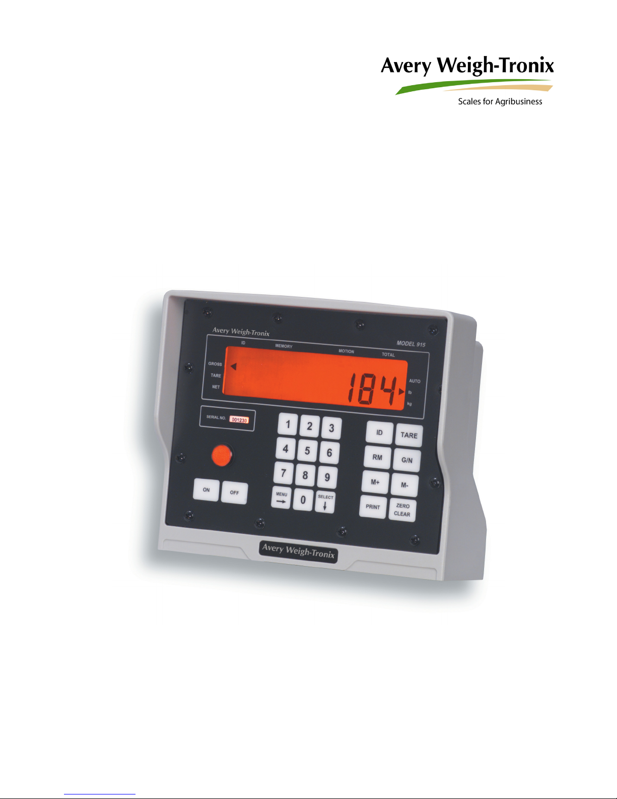
Model 915A
Indicator
User Instructions
29748-0014 Issue AE April 2013
Page 2

© Avery Weigh-Tronix, LLC 2013 All rights reserved.
No part of this publication may be reproduced, stored in an electronic retrieval system, or transmitted in any form
or by any means, electronic, mechanical, photocopying, recording or otherwise without the prior written consent of
the copyright owner, or as permitted by law or under license. Full acknowledgment of the source must be given.
Avery Weigh-Tronix is a registered trade mark of the Avery Weigh-Tronix, LLC. This publication was correct at the
time of going to print however, Avery Weigh-Tronix, LLC reserves the right to alter without notice the specification,
design, price or conditions of supply of any product or service at any time.
All third party brands and product names used within this document are trademarks or registered trademarks of
their respective holders.
915A_u_en_29591_0012.book
Page 3

Table of Contents
Chapter 1 General information and warnings ......................................................................................... 3
About this manual ..............................................................................................................3
Text conventions ......................................................................................................... 3
Special messages ....................................................................................................... 3
Customer Service Information ........................................................................................... 3
Chapter 2 Specifications ........................................................................................................................... 4
Chapter 3 Options ...................................................................................................................................... 5
Chapter 4 Introduction .............................................................................................................................. 6
Keys ................................................................................................................................... 6
Chapter 5 Cable Connections and Power Requirements ...................................................................... 8
Chapter 6 Indicator Operation .................................................................................................................. 9
Gross Weighing .................................................................................................................9
ID Number Entry ................................................................................................................9
View Current ID ........................................................................................................... 9
Clear Current ID .......................................................................................................... 9
Animal Weighing .............................................................................................................. 10
How to View Individual Animal Weights .................................................................... 10
How to View the Animal Statistics ............................................................................. 11
Printing Reports ...............................................................................................................12
Clear all Statistics from Memory ...................................................................................... 12
Setting Auto-LOC ............................................................................................................. 13
Viewing and Setting the Time .......................................................................................... 13
Viewing and Setting the Date ........................................................................................... 13
Checking Battery Voltage ................................................................................................ 14
Diagnostic Tests .............................................................................................................. 14
Chapter 7 Troubleshooting ..................................................................................................................... 16
Power-On Failure ............................................................................................................. 16
Stalled Display Following Power-On ................................................................................ 17
Indicator Lock-Up ............................................................................................................. 18
Inaccurate Weight Readings ............................................................................................ 18
Alarm Light Function ........................................................................................................ 19
Measuring Supply Battery Voltage ................................................................................... 19
Service Repairs ................................................................................................................19
Display Messages ............................................................................................................ 20
Chapter 8 Miscellaneous Information .................................................................................................... 21
Mounting the Model 915A ................................................................................................ 21
RD 912 Remote Display .................................................................................................. 22
Optional Radio Remote Transmitters (XM710-L and XM910) and Receiver ................... 22
Chapter 9 User’s Menu ............................................................................................................................ 23
Chapter 10 Appendix A: Customizing Printouts ................................................................................... 24
Layout 1 - 5 ...................................................................................................................... 24
ASCII ................................................................................................................................ 25
To Delete All ASCII Characters ................................................................................. 26
Enabling Auto-Print .......................................................................................................... 26
Model 915A Indicator User Manual 1
Page 4

2 Model 915A Indicator User Manual
Page 5

1 General information and warnings
1.1 About this manual
This manual is divided into chapters by the chapter number and the large text at the top
of a page. Subsections are labeled as shown by the 1 and 1.1 headings shown above.
The names of the chapter and the next subsection level appear at the top of alternating
pages of the manual to remind you of where you are in the manual. The manual name
and page numbers appear at the bottom of the pages.
1.1.1 Text conventions
Key names are shown in bold and reflect the case of the key being described. This
applies to hard keys and onscreen or soft keys.
Displayed messages appear in b
message.
Screen labels and labels within screens appear in italic type
displayed label.
old italic type and reflect the case of the displayed
1.1.2 Special messages
Here are examples of messages you will see in this manual.
NOTE: This is a Note symbol. Notes give additional and important information, hints
and tips that help you to use your product.
1.2 Customer Service Information
24 hours a day 7 days a week Customer Support
Avery Weigh-Tronix is dedicated to customer service. We understand downtime is not
an option for AG producers and we're ready to help anytime. The technical support
team for all Avery Weigh-Tronix agri-business scales is available 24 hours a day 7 days
a week.
and reflect the case of the
Ag Technical Support Group
USA and Canada Toll free Phone: (800) 458 - 7062
Outside USA: (507) 238-8261
Tech Support Phone 7:00 am to 5:00 pm CST (800) 458-7062 Ext. 8261
Tech Support Phone/ after hours answering 5:00 pm to 7:00 am CST (800) 458-7062
Service e-mail: u
Model 915A Indicator User Manual 3
Page 6

2 Specifications
Indicator Enclosure Impact, dust, and water resistant - structural polycarbonate
Display 8 digit, seven segment LCD, 1.0 inch high characters, 10
Display Rate One, two, or five times per second
Accuracy +/- 0.1% of applied load or +/- one division, whichever is greater
Linearity +/- .01 % of capacity
Repeatability +/- .01% of capacity, +/- one division, whichever is greater
Power Requirements Typical: 12 VDC @ 95 mA (1.14 watts)
Environment -20° F to 140° F (-29° C to 60° C) to 95% non-condensing humidity
enclosure stands up to inclement weather and high vibration mobile
farm applications. Standard Weigh-Tronix mounting bracket.
(Dimensions: 8.75 high x 10.5 wide x 6.5 deep)
annunciators*, and fiber optic back-lighting. * annunciatorsGROSS, TARE, NET, ID, MEMORY, MOTION, TOTAL, AUTO, LB,
and KG
12VDC @ 180 mA (2.16 watts) for 5-pin 4 weigh-bars
Range: 10 DVC @ 89 mA (0.9 watts) to 18 VDC @ 555 mA (10
watts). Negative ground system.
Weigh Bar® Drive Capacity Ten 350 ohm Weigh Bars
Calibration Front panel calibration and spanning for all types of weigh bars and
load cell applications up to 999999 lb. or kg.
Divisions .01, .02, .05, .1, .2, .5, 1, 2, 5, 10, 50, 100, 200, 500 lb. or kg.
Zero Balance Range +/- 1 mV/V via front panel push button
Analog Span 0.20 mV/V to 1.0 mV/V (full scale)
Automatic Zero Tracking OFF, +/-0.5, 1.0, 2.0, 3.0, 5.0, 10.0 divisions
Motion Detection Window OFF, +/-0.5, 1.0, 2.0, 3.0, 5.0, 10.0 divisions
Motion Filtering Normal, intermediate, and high
Alarm Output Comes on standard in the Auto Accumulate/Print mode when Auto-
Accumulating takes place.
4 Model 915A Indicator User Manual
Page 7

3 Options
RS232 serial output Includes battery backed up time and date
Baud rate selectable: 9600, 4800, 2400, 1200, 600 and 300
xon/xoff, 8 data bits, one stop bit, no parity
Initiate serial transmission through- print button, enquire characters, and auto
print after accumulate and after motion ceases.
Two format selectable printouts along with single line programmable (40)ASCII
characters.
Remote Display Output To be used with the RD912 remote display.
Remote (XM710-L, XM910) Includes optional remote radio receiver, and transmitter.
Two separate inputs on the M915A will each be programmable to function as
Zero, Tare, G/N, RM, M+, M-, or Print.
Frequency: 303 MHz
Frequency on by key switch, causes activation of Input-1 or Input-2
Model 915A Indicator User Manual 5
Page 8
4 Introduction
ID
GROSS
TARE
NET
MEMORY MOTION TOTAL
AUTO
lb
kg
SERIAL NO.
ON OFF
1
2
5
4
0
8
7
3
6
9
ID
PRINT
SELECT
MENU
TARE
ZERO
M+
CLEAR
G/N
RM
M-
The Model 915A is a general purpose animal weight indicator designed to operate at
12VDC. It has a companion remote display called the RD912. The indicator can record
1000 animal weighments and give statistics on count, total weight, average weight,
highest weight and lowest weight.
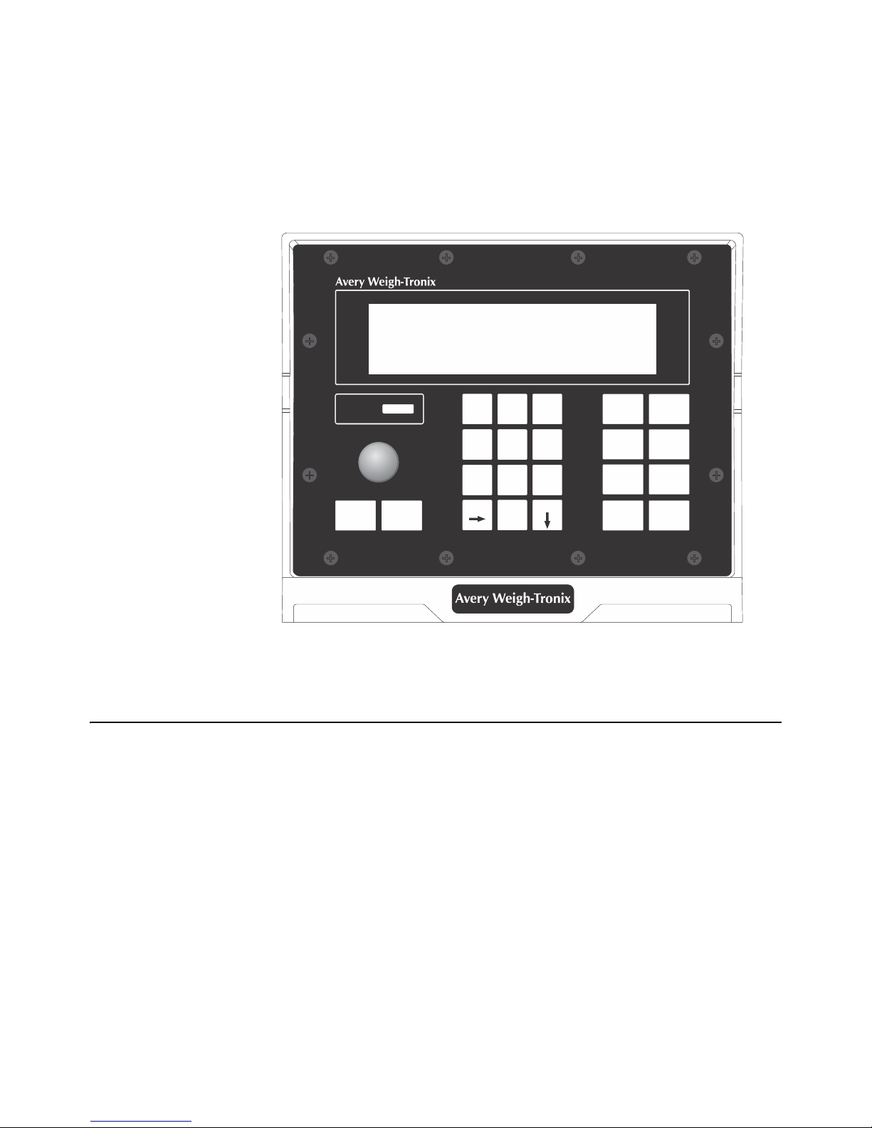
Figure 4.1 shows the Model 915A front panel.
4.1 Keys
The front panel consists of the digital display window with annunciators, numeric
keypad and the following keys:
ON Use this key to power up the 915A indicator
OFF Use this key to power down the 915A indicator
MENU Use this key to access the menus and scroll right in the menu structure
SELECT Use this key to make selections in the menus and to scroll down in the menu
ID Use this key to access the ID function
TARE Disabled
RM Use this key to recall a weight stored in memory
structure
Figure 4.1 Model 915A Indicator
6 Model 915A Indicator User Manual
Page 9

G/N Use this key to escape back to the gross weight
M+ Use this key to record/add a displayed weight to the memory
M- Use this key to delete the last recorded weight in memory
PRINT Use this key to output displayed information to a peripheral device
ZERO/CLEAR Use this key to zero the scale or clear a keyed in value from the display
Model 915A Indicator User Manual 7
Page 10
5 Cable Connections and Power Requirements
FUSE FUSE
Remote Display/
RS-232 Connector
(Optional)
Weigh Bar Connector
(7 pin)
Power Fuse
Power Connector
Alarm Connector
Alarm Fuse
Pin A = +12 VDC
Pin B = Ground
FUSE FUSE
Remote Display/
RS-232 Connector
(Optional)
Weigh Bar Connectors
(4 or 5 pins)
Power Fuse
Power Connector
Alarm Connector
Alarm Fuse
Pin A = +12 VDC
Pin B = Ground
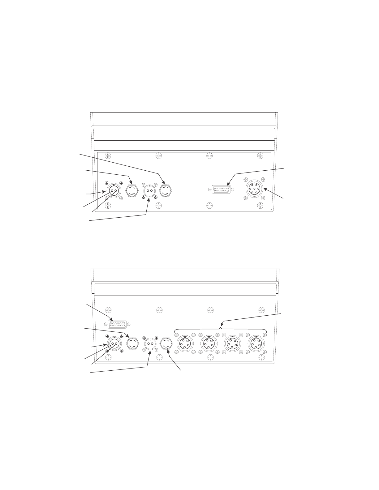
Make sure all cables are connected as shown in Figure 5.1 and Figure 5.2.
Voltage to the Model 915A must be 10-18 volts DC, negative ground only. If voltage is
be
tween 8-10 volts, Lo-bAt is displayed on the indicator. Dropping below eight volts will
cause the Model 915A to automatically shut itself off, protecting the battery from being
completely drained. Consult the Model 915A Service Manual for instructions on
disabling the automatic shut-off.
8 Model 915A Indicator User Manual
Figure 5.1 Indicator with One Weigh Bar Connector
Figure 5.2 Indicator with Four Weigh Bar Connectors
Page 11

6 Indicator Operation
6.1 Gross Weighing
1. Power up the indicator by pressing ON.
Indicator powers up in mode that was active prior to turning off.
2. Verify the scale is empty and zero the scale by pressing ZERO.
0
is displayed. Zeroing can only occur if there is no motion on the scale.
3. Place weight on the scale.
Gross weight is displayed.
6.2 ID Number Entry
You may enter an 8 digit numerical ID number to be included in the printouts.
1. From the gross weighing mode use the keypad and enter the ID number.
2. Press ID.
6.2.1 View Current ID
If no ID is currently programmed, then ID key displays “no Id” for 2 sec., and returns to
the Gross mode.
1. Press ID.
6.2.2 Clear Current ID
1. Press ID to display current ID.
ID number is shown on the display.
The ID ann
then returns to the gross mode.
Current ID is shown for two seconds and then returns to the gross mode.
unciator is turned on. ID number is displayed for 2 seconds,
2. Press ZERO/CLEAR wh
Model 915A Indicator User Manual 9
Current ID is displayed.
ile ID is displayed.
ID is cleared, and returns to gross mode.
Page 12

6.3 Animal Weighing
You can perform animal weighing with Auto-LOC on or off. See the section Configuring
Auto-Loc.
NOTE: Layout #3, shown in Printing Reports, will be printed if you press M+ with
Auto-Print enabled. It will also be printed if Auto-Loc is enabled.
With Auto-LOC on:
As the animal walks on the scale and the weight s
for two seconds and the weight is automatically stored in the first available record (1-
1000).
The display will show the record
by 20% or more. At this point the display returns to live gross weighing and the alarm
light turns off.
In this mode the M+/M- keys are disabled.
With Auto-LOC off:
After the animal walks on the
The memory channel and weight will remain displayed and the alarm light will come on
for two seconds. You cannot record the weight again until the weight drops by 20%. If
you try, the display will show Can’t.
If you want to erase a weight you recorded in error, press the M- key
show the count with the new locked-on weight. This can be done with or without the
animal on the scale.
number and the locked weight until the weight drops
scale, you must press the M+ key to record the weight.
6.3.1 How to View Individual Animal Weights
Follow these steps to view each animal’s weight:
1. From gross weighing mode, press the RM key
tabilizes, the alarm light comes on
. The display will
.
2. Press the M+ or M- key to scro
To scroll more rapidly through the list, press and hold the M+ or M- key.
3. Press the G/
10 Model 915A Indicator User Manual
The last recorded weight and channel number is displayed.
ll through the list of animals and their weights.
N key to return to gross weighing mode.
Page 13

6.3.2 How to View the Animal Statistics
Once you have recorded a series of animal weights you can view the results by
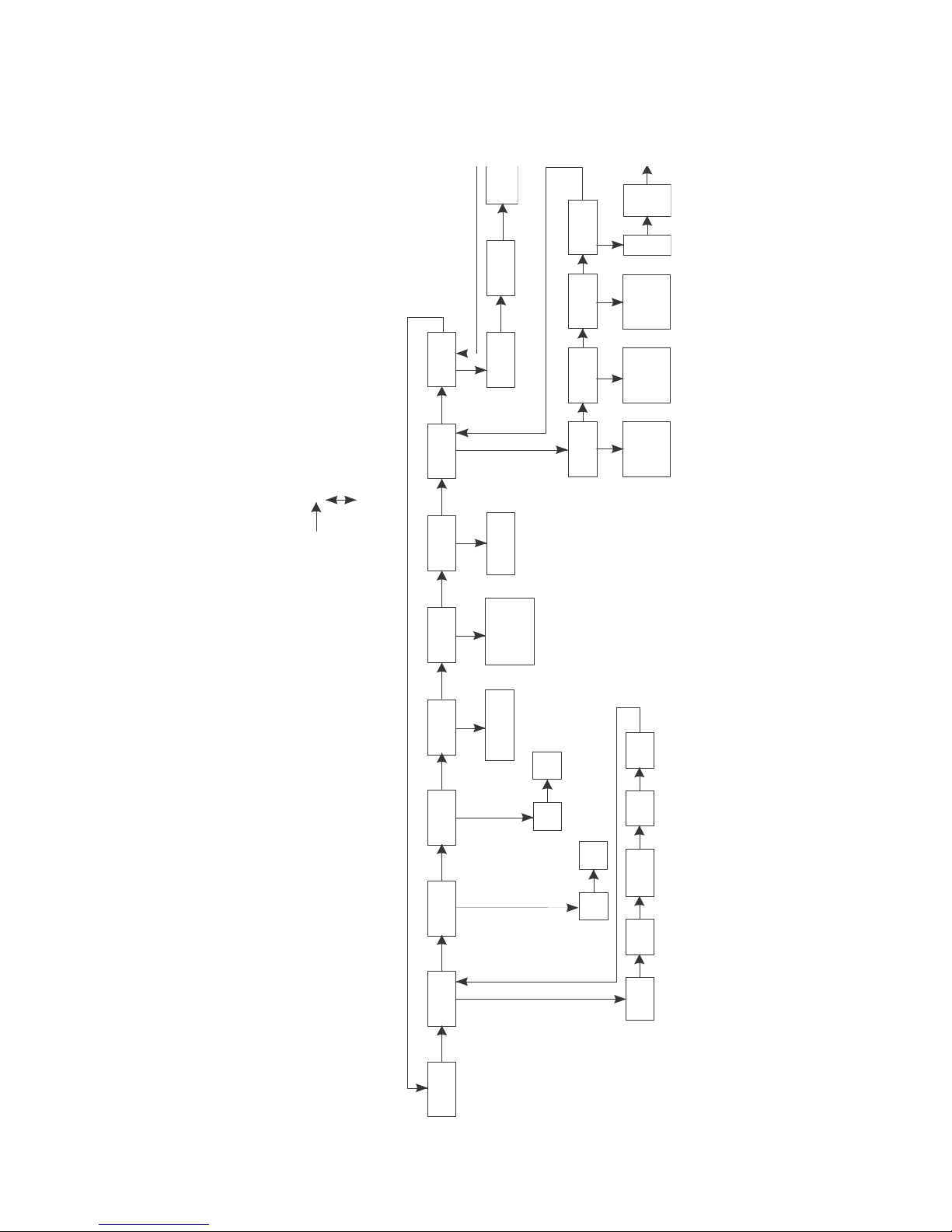
entering the StAts item in the user menu. See Figure 6.
Under STATS you can view the following by using the SELECT and MENU keys:
l total count of animals weighed
l total weight of all animals weighed
l average weight of all animals weighed
l highest recorded animal weight
l lowest recorded animal weight
1. From gross mode press MENU and...
StAts is displayed.
2. Press SELECT
The first stat, Count, is displayed.
3. Press SELECT to see the total number of animals weighed.
4. Press SELECT again to return to the StAts display.
5. Press MENU to go to the next stat. Repeat steps 3-5 to see all the stats.
6. Press G/N to return to the gross weighing mode.
Model 915A Indicator User Manual 11
Page 14
6.4 Printing Reports
Layout #1
Layout #2
Layout #3
Layout #4
Layout #5
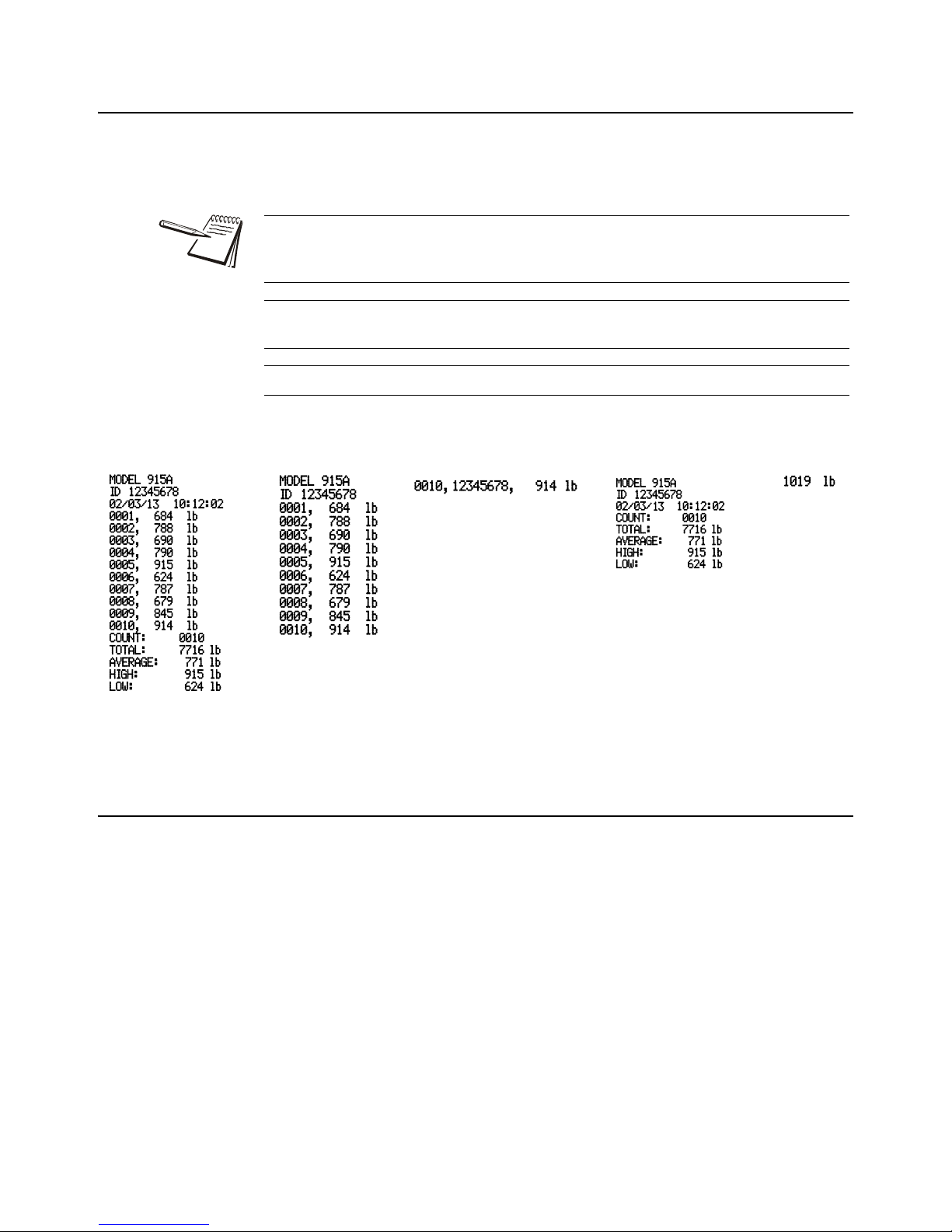
To print out a report, press the PRINT key. One of the following layouts will be printed
depending on which you have chosen through the configuration menu. See Appendix
A for instructions on choosing a layout.
NOTE: If AUTO-PRINT is enabled (see your Appendix A) and AUTO-LOC is on,
Layout #3, shown at right, is printed as soon as an animal’s weight is stable. if AutoLoc is off when pressing M+, Layout #3 is automatically printed.
You can customize the first line in the examples shown below (Model 915A). See
Appendix A.
ID will only be printed if an ID is entered.
Figure 6.1 Print Layouts
6.5 Clear all Statistics from Memory
Follow these steps to remove all the statistics from memory.
1. From gross mode repeatedly press MENU un
Clr-StAt is disp
2. Press SELECT
yes or
no is displayed.
3. Use the MENU key to toggle between the choices. Press SELECT when the
choice yo
4. Press the G/N key to return to gross weighing mode.
u want is displayed.
Stats are cleared or not depending on your choice.
layed.
til
12 Model 915A Indicator User Manual
Page 15

6.6 Setting Auto-LOC
Follow these steps to turn Auto-LOC on or off.
1. From gross mode repeatedly press MENU until Auto-LOC is displayed.
2. Press SELECT.
ON or OFF is displayed.
3. Press MENU to toggle between the choices. Press SELECT when the choice
you want is displayed.
Auto-LOC is displayed.
4. Press the G/N key to return to gross weighing mode.
6.7 Viewing and Setting the Time
1. From gross mode repeatedly press MENU until Hour is displayed.
2. Press SELECT.
The time will be displayed in hours, minutes and seconds.
3. Enter the correct time allowing spaces for hours, minutes and seconds.
For example, 1:59 would be entered as 15900.
4. Press SELECT.
Hour is redisplayed.
5. Press G/N to return to gross weighing mode.
6.8 Viewing and Setting the Date
1. From gross mode repeatedly press MENU until Date is displayed.
2. Press SELECT.
The date is displayed in month, day, year. (For kg: day, month, year)
3. To change the date, key in the new numbers.
4. Press SELECT.
Date is redisplayed.
5. Press G/N to return to gross weighing mode.
Model 915A Indicator User Manual 13
Page 16

6.9 Checking Battery Voltage
1. From gross/net mode repeatedly press MENU until battErY is displayed.
2. Press SELECT.
The input voltage of the battery or power source will be displayed.
Voltage to the Model 915A must be 10-18 volts DC. If voltage is between
8-10 volts, Lo-bAt is displayed on the indicator. Dropping below eight
volts will cause the Model 915A to automatically shut itself off, protecting
the battery from being completely drained.
6.10 Diagnostic Tests
There are four tests available to assist troubleshooting in these areas:
l display
l buttons
l serial
l relay
1. From gross/net mode repeatedly press MENU until tESt is displayed.
2. Press SELECT.
diSPlAY is displayed. This is the display test.
3a. Press SELECT to perform a test of the display segments and annunciators …
The display alternately lights all the display segments and annunciators.
Press SELECT to end the test
OR
3b. Press MENU twice to go to the next test.
buttonS is displayed. This is the buttons test.
4a. Press SELECT to perform a test of the front panel buttons.
When you press any key, that key name will appear in the display. Press
MENU to stop the test. Display will show SEriAl.
OR
4b. Press MENU to go to the next test.
SEriAl is displayed.
5. SEriAl is the serial test. This will tell you if pins 2 and 3 are connected. If they
are connected loop is displayed when you press SELECT.
no loop is displayed when you press SELECT if pins 2 and 3 are not
connected.
6. Press MENU to go to the next test.
14 Model 915A Indicator User Manual
rELAY is displayed. Use this test to check alarm light function.
Page 17

7. Press SELECT.
OFF is displa
yed.
You can press SELECT at any time to return to the rELAY display.
8. Press MENU on
FLASH is displa
8a. Press MENU ag
ce to cause the light to flash on and off.
yed.
ain to cause the light to stay on.
on is displayed.
8b. Press MENU ag
OFF is displa
ain to shut off the light.
yed.
9. Press SELECT.
rELAY i
s displayed.
10. Press MENU.
tESt is displa
yed.
11. Press MENU.
SoFt is d
isplayed. This lets you see the part number and revision level of
the software.
12. Press SELECT.
First part of the software number is displayed.
13. Repeatedly press MENU to scroll throu
and return to the SoFt display.
14. Press MENU on
e more time and you are back in the gross/net mode.
gh the part number and revision level
Model 915A Indicator User Manual 15
Page 18

7 Troubleshooting
If you experience problems in the operation of your system, read through these
troubleshooting steps and perform those which are appropriate. This information may
help you to correct the following operational difficulties without calling your supplier or
sending your equipment in for repair:
l Power-on
l Stalled Display Following Power-on
l Indicator Lock-up
l Inaccurate Weight Readings
l Alarm Light Malfunction
l Measuring the Supply Battery Voltage
Instructions for sending an indicator in for repair are provided in the last section under
Service Repairs.
7.1 Power-On Failure
If your indicator doesn’t power-on, check the following possible problem sources in the
order given. Attempt to power-on after trying each of these four troubleshooting steps:
1. Check Battery Voltage. Required voltage is 10-18 volts DC negative ground. If
the voltage is between 8-10 volts, the indicator will display Lo-bAt. The indicator
will automatically turn off if the incoming voltage drops below 8 volts or rises
above 18 volts.
2. Disconnect and Check Power Cable Connector at the vehicle or AC to DC
converter, clean if necessary, and reconnect.
3. Replace Fuses. Sometimes, a bad fuse can be recognized by an obvious
break in the wire filament. However, such a break is not always observable,
and getting a successful power-on after changing a fuse is often the only way
of knowing that the fuse was indeed defective.
Make sure new fuses are the proper size and have a current rating of five
amperes. Using a fuse with too high a current rating can cause costly damage
to the indicator and will void your warranty. The same is true for substituting
wire, a nail, or any other object in place of a fuse.
Place nothing in the fuse connector except a proper fuse.
Change one fuse at a time (see instructions below). Try to power-on after
changing the first fuse; if unsuccessful, change the second fuse and try to
power on again. If changing the second fuse fails to allow successful poweron, proceed to the next trouble shooting step.
16 Model 915A Indicator User Manual
Page 19

To replace a fuse, first locate fuse caps on the bottom panel of the indicator.
Then:
1. Turn cap counterclockwise and lift out fuse & cap assembly.
2. Remove old fuse from cap and insert new fuse.
3. Replace fuse & cap assembly in fuse connector.
4. Test Indicator and Cables to isolate the source of the problem.
a. Disconnect all cables on bottom panel of Indicator except for power
®
cable. Do disconnect Weigh Bar
cables, and, if present, alarm cable
and printer/remote display cable.
b. Now try powering-on. If this is not successful, your problem is in the
indicator and you should contact your supplier.
c. If you are able to power-on with only the power cable connected, your
problem is most likely not in the indicator; continue troubleshooting.
d. With power still on, plug in cables, one at a time — Weigh Bar cables
first, then alarm cable, then printer/remote display cable — until plugging
in one of the cables causes the indicator to shut off. That cable is the bad
one and needs to be repaired or replaced.
7.2 Stalled Display Following Power-On
This category of problems can exhibit any one of the following symptoms:
l An illegible display that cannot be zeroed and from which you cannot exit;
l A legible display, such as HELLO, that cannot be zeroed and from which you
cannot exit;
l An illuminated backlight with no characters displayed and allowing no exit.
l If the red illumination on the display is visible, telling you the indicator has
power (on a sunny day you may have to shade the display), you can
possibly restore the display function by doing a reinitialization (explained
below).
To Reinitialize a Stalled Indicator:
If the display says Hl instead of HELLO following a reinitialization poweron, your indicator has a potential problem and should be checked. Contact
your supplier.
1. Press OFF.
2. Press ZERO/CLEAR and hold in, while you
3. Press and release ON.
4. Then release ZERO/CLEAR.
Model 915A Indicator User Manual 17
Page 20

7.3 Indicator Lock-Up
A locked up indicator is represented by an illuminated alarm light and a display of Error.
1. Shut off the alarm by pressing any key.
2. Test the Weigh Bar cables to isolate the source of the lock up problem, as
follows:
a. Disconnect all Weigh Bars.
b. Try to zero the indicator by pressing GROSS and ZERO/CLEAR.
l If you are unable to zero the indicator with the Weigh Bars disconnected, the
problem is in the indicator and you should contact your supplier.
l If you are able to zero your indicator with the Weigh Bars disconnected, then
the problem is probably in the cabling or the Weigh Bars and you should
continue troubleshooting.
3. Reconnect all Weigh Bars. You will see Error displayed again.
4. If your Weigh Bar connectors have the four-pin configuration, disconnect one
Weigh Bar and connect an adapter plug in its place.
If your Weigh Bar connectors have the five-pin configuration, disconnect one
Weigh Bar. No adapter plug is necessary.
5. Try to zero the indicator.
Repeat Steps 4 and 5 with each Weigh Bar cable, making sure each time that
all cables are connected except the one you removed (for five-pin connector)
or replaced with an adapter plug (for four-pin connector).
A defective Weigh Bar may be easily recognized with this method — when a
defective bar is replaced with an adapter plug (for four-pin connector), or
removed (for five-pin connector), the indicator will zero properly.
7.4 Inaccurate Weight Readings
First: Visually inspect the scale system for apparent problems and improper installation:
1. Check each cable, from source to indicator, for stress, cuts, breaks, or
abrasions.
2. Unplug and reconnect each connector at the indicator to verify that it is tight
and making good contact.
3. Check between supporting structure and weighing structure for debris that
might restrict Weigh Bar movement.
4. Make sure the supporting structure and weighing structure do not touch each
other at any point except at the Weigh Bars.
Next: Compare weight readings for all Weigh Bars:
Position a person or heavy object on the platform above each Weigh Bar, one bar at a
time, and compare weight readings for the same person or same object.
18 Model 915A Indicator User Manual
Page 21

For each weighing, the weight itself will be off-center, favoring a single Weigh Bar;
therefore, none of the readings will be accurate.
However, your readings obtained by weighing the same person or object above each
Weigh Bar should be nearly identical to each other. A single Weigh Bar reading that is
significantly different from the others is probably defective.
7.5 Alarm Light Function
If your external alarm works properly but the alarm light fails to illuminate when it
should, a problem exists with the alarm light. Please send in the indicator for repair.
7.6 Measuring Supply Battery Voltage
To check input voltage to indicator (battery voltage):
1. Press MENU …
tArE is displayed.
2. Press MENU repeatedly until …
3. Press SELECT …
4. Press SELECT …
5. Press G/N to return to weighing mode.
7.7 Service Repairs
If you find the indicator or one or more of the Weigh Bars to be defective, contact your
supplier, or send your equipment back to the factory for repair, postage prepaid.
Include the following information:
1. Your name and address
2. Supplier name and address
3. Date of purchase
4. Important: An informal note describing symptoms of the problem.
battErY is displayed.
Incoming battery voltage is displayed.
battErY is displayed.
Model 915A Indicator User Manual 19
Page 22

7.8 Display Messages
H E L L O Indicator is being reinitialized. Message is displayed briefly at time
— — — — Indicator is in state of over-capacity.
— — — — Indicator is in state of under-capacity.
E r r o r System is not functioning properly. Weight is not being calculated
P r i n t Indicator is transmitting data. Appears after pressing the PRINT
CAn’t Displayed when attempting to tare when a gross weight is
of power-on.
because scale weight is too high or too low. (Refer to information
on “Indicator Lockup” in Troubleshooting section of manual.)
key when printing all memory channels.
negative or when motion is occurring.
20 Model 915A Indicator User Manual
Page 23

8 Miscellaneous Information
8.1 Mounting the Model 915A
The Model 915A mounts on a quick-detach bracket. Weld or bolt the quick-detach
bracket into place, as follows:
1. Choose a mounting location that is
l convenient for operation of the indicator, and
l protected from moving parts or from other moving machinery.
2. Hold the indicator at the proposed mounting location, and verify that the
display is legible and the controls accessible.
3. Positioning the quick-detach bracket with the wider end at the top, mark the
desired mounting location. If bolting, use the quick-detach bracket as a
template and mark and drill holes.
4. Weld or bolt the quick-detach bracket at the appropriate location. If bolting,
use double nuts or self-locking nuts to protect both indicator and machinery.
5. Insert the indicator bracket into the quick-detach bracket and push it down into
place.
6. For mobile applications, wrap and twist a strong wire around the indicator
bracket and the quick-detach bracket to stabilize the mounting.
Model 915A Indicator User Manual 21
Page 24
8.2 RD 912 Remote Display
ID
GROSS
TARE
NET
MEMORY MOTION TOTAL
AUTO
lb
kg
SERIAL NO.
XM710-L
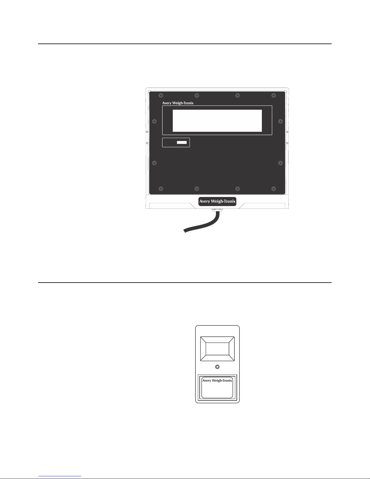
The RD912 is a remote display that is compatible with the Model 915A. (An RD912
output option is required on the Model 915A for interfacing.) The interface cable plugs
directly into the bottom of the Model 915A (refer back to Figure 5.1. When using the
remote display, any data displayed on the Model 91
5A is also displayed on the RD912.
Figure 8.1 Model 912 Remote Display
8.3 Optional Radio Remote Transmitters (XM710-L and XM910)
and Receiver
An optional radio remote transmitter and receiver can be installed.
This option lets the user configure the XM710 to act as a ZE
TARE or G/N key and work at up to 100 feet away, It can be installed in either the Model
915A or the RD912..
Figure 8.2 Radio Remote
RO, PRINT, M+, M-, RM,
22 Model 915A Indicator User Manual
Page 25
9 User’s Menu
CLr-Stat
NO
ON
YES
OFF
Hour Date
Te st
HH MM SS
MM DD YYorDD MM YY
Display
Display
segment
test
Serial
key
Loop or
no loop
Press MENU
Units configured
for kgs, use
DD MM YY
soft
xxxxx- -xxxx
Auto-Loc
Relay
Gross Stats
Count
Average
Total High Light
Press and
hold MENU
Press the key to scroll in the menu.
Press the key to move in the menu
MENU
SELECT
leve
Revisi
Press MENU
Flash
Off
Buttons
Battery
Input voltage
Press any
Model 915A Indicator User Manual 23
Page 26

10 Appendix A: Customizing Printouts
10.1 Layout 1 - 5
The hidden E key is between the 9 and the M+ keys on the indicator
Below are the steps to choosing Layout 1 - 5.
1. Key in 91
2. Press hidden E key an
3. Press SELECT .
4. Press MENU r
5. Press SELECT.
6. Press MENU r
7. Press SELECT.
8. Press MENU un
9. Press MENU to scro
5.
915 i
s displayed.
915 E is displayed.
ConF is
bAUd is disp
1 - 5 is
That layout is now active.
displayed.
epeatedly until SEriAl is displayed.
layed.
epeatedly until LAYoUt is displayed.
displayed.
til the layout you want is displayed, then press SELECT.
ll to next desired option or G/N to exit.
d hold for two seconds.
24 Model 915A Indicator User Manual
Page 27

10.2 ASCII
The ASCII parameter lets you customize the first line of Layouts #1, 2 and 4. You key
in the ASCII code number for the character you want to print. You can use up to 40
characters in the line. The ASCII codes are shown in Table 1.
1. Key in 915.
s displayed.
915 i
2. Press hidden E key an
915 E is displayed.
3. Press SELECT.
ConF is
4. Press MENU r
5. Press SELECT.
bAUd is disp
6. Press MENU r
7. Press SELECT.
1 _ is d
insert.
8. Key in the control code from Table 6 and press MENU.
2 _ i
Following is an example of how to enter Mo
Enter the following control codes.
displayed.
epeatedly until SEriAl is displayed.
epeatedly until ASCII is displayed
s displayed.
d hold for two seconds.
layed.
isplayed. The 1 refers to the first of the 40 characters you can
del 915A, <CR><LF>:
Sequence # Control Code # Control Character
01 #77 M
02 #79 O
03 #68 D
04 #69 E
05 #76 L
06 #32 SPACE
07 #57 9
08 #49 1
09 #53 5
10 #65 A
11 #13 Carriage Return
12 #10 Line Feed
To edit an existing sequence, display the sequence number you want to change, key
in the new ASCII code number and press
Press the G/N key when you are done.
9. Repeat step 8 until all control codes are entered, and press SE
ASCII is displayed.
SELECT to return to the ASCII display.
LECT.
Model 915A Indicator User Manual 25
Page 28

10. Press G/N key to exit programming mode and return to the gross weighing
mode.
10.2.1 To Delete All ASCII Characters
1. Access Serial-ASCII in the configuration menu.
ASCII is displayed.
2. Press the ZERO/CLEAR key.
ASCII blinks and all the control codes are cleared.
10.3 Enabling Auto-Print
1. Key in 915.
915 is displayed.
2. Press hidden E key and hold for two seconds.
915 E is displayed.
3. Press SELECT.
ConF is displayed.
4. Press MENU repeatedly until SEriAl is displayed.
5. Press SELECT.
bAUd is displayed.
6. Press MENU repeatedly until Auto is displayed
7. Press SELECT.
8. Press MENU to display either OFF or ON
9. Press SELECT.
Depending on your choice, auto print is now either on or off.
10. Press MENU to scroll to next desired option or G/N to exit.
26 Model 915A Indicator User Manual
Page 29
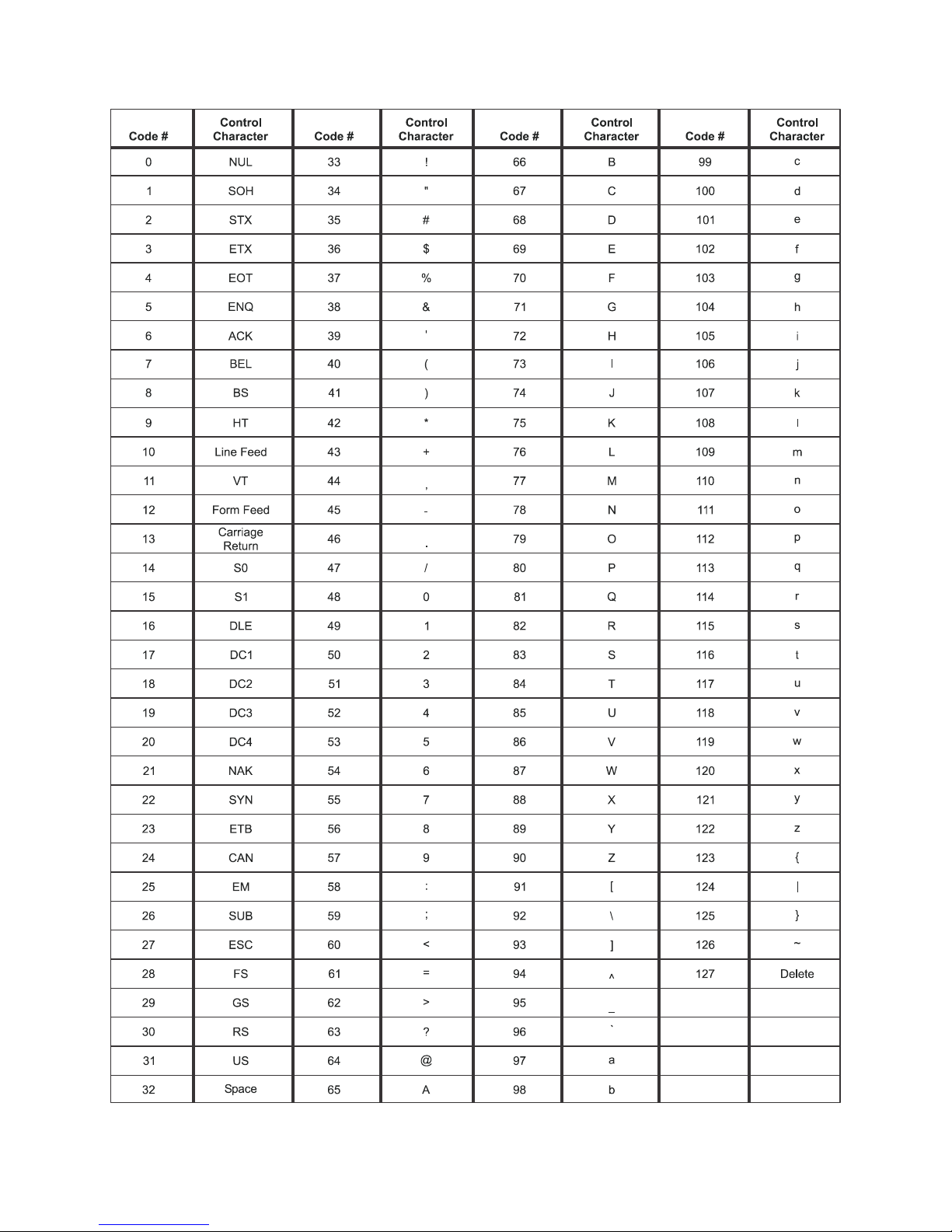
Table 10.1 Table 1 ASCII Control Codes
Model 915A Indicator User Manual 27
Page 30

28 Model 915A Indicator User Manual
Page 31

Page 32
To access manuals on
the Ag website
Avery Weigh-Tronix USA
1000 Armstrong Dr.
Fairmont MN 56031 USA
Tel:507-238-4461
Fax:507-238-4195
Email: [email protected]
www.agscales.com
Avery Weigh-Tronix UK
Foundry Lane,
Smethwick, West Midlands,
England B66 2LP
Tel:+44 (0) 8453 66 77 88
Fax: +44 (0)121 224 8183
Email: [email protected]
www.averyweigh-tronix.com
 Loading...