

Page 1
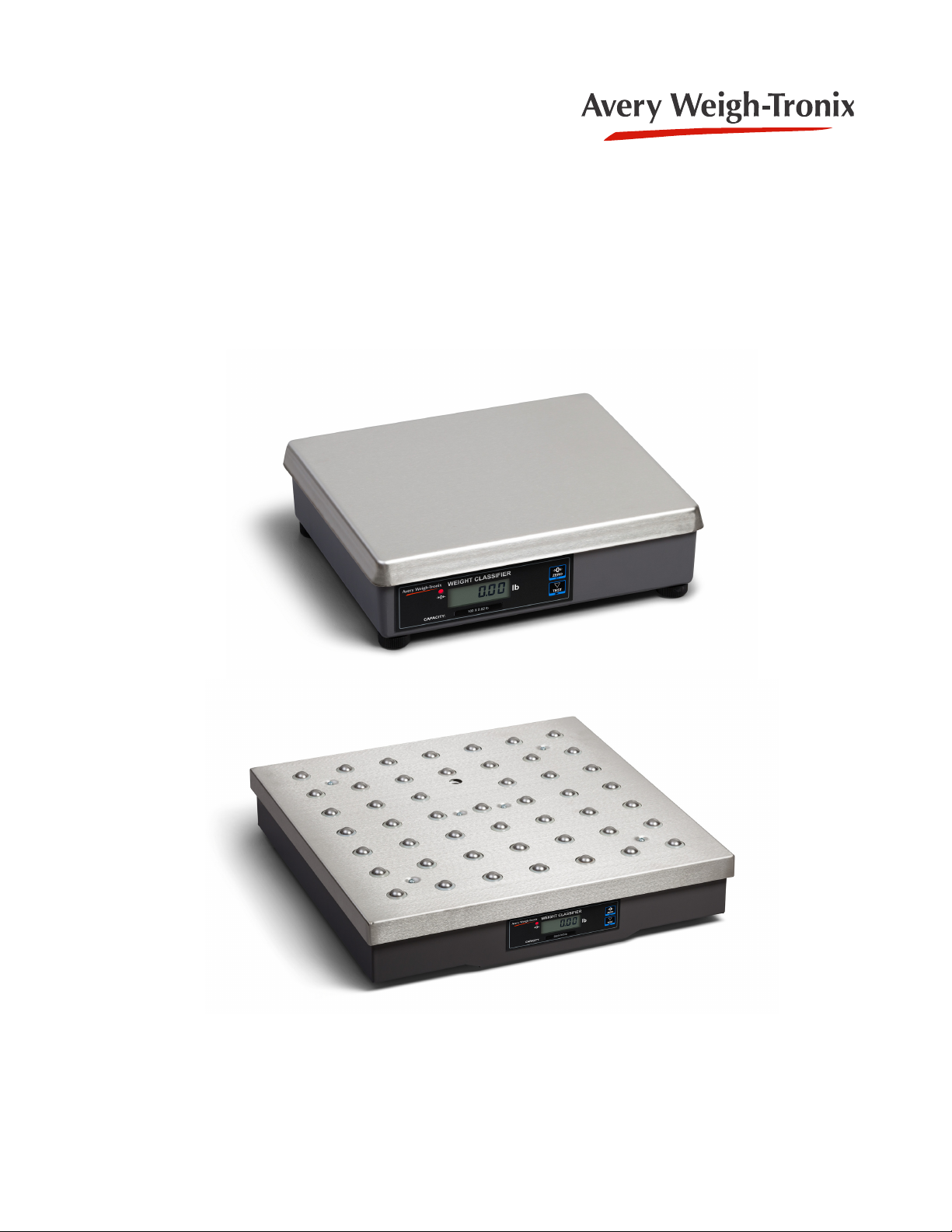
Model 7821
User Instructions
AWT35-501542
Issue AA
Page 2

Avery Weigh-Tronix is a trademark of the Illinois Tool Works group of companies whose ultimate parent company is
Illinois Tool Works Inc (“Illinois Tool Works”). Copyright © 2016 Illinois Tool Works. All rights reserved.
No part of this publication may be reproduced by making a facsimile copy, by the making of a copy in three dimensions of a two-dimensional
work and the making of a copy in two dimensions of a three-dimensional work, stored in any medium by electronic means, or transmitted in
any form or by any means, including electronic, mechanical, broadcasting, recording or otherwise without the prior written consent of the
copyright owner, under license, or as permitted by law.
This publication was correct at the time of going to print, however Avery Weigh-Tronix reserves the right to alter without notice the
specification, design, price or conditions of supply of any product or service at any time.
7821_u_en_501542.book
Page 3

Table of Contents
page
Table of Contents ...................................................................................................................................... 3
Chapter 1 General information and warnings ......................................................................................... 5
About this manual ..............................................................................................................5
Text conventions ......................................................................................................... 5
Special messages ....................................................................................................... 5
Installation .......................................................................................................................... 6
Electrical installation .......................................................................................................... 6
Pluggable equipment ................................................................................................... 6
Wet conditions ............................................................................................................. 6
Routine maintenance ......................................................................................................... 7
Cleaning the machine ........................................................................................................ 7
Training .............................................................................................................................. 7
FCC and EMC declarations of compliance ........................................................................ 8
Chapter 2 Specifications ........................................................................................................................... 9
Chapter 3 Unpacking and Installing the Scale ...................................................................................... 10
Chapter 4 Operation ................................................................................................................................ 11
Power Up Test Sequence ................................................................................................ 11
Performing a Normal Weighment ..................................................................................... 11
Chapter 5 Modes of Operation ............................................................................................................... 12
Accessing the Menu ......................................................................................................... 12
Zero and Units Key .................................................................................................... 12
Display ....................................................................................................................... 13
Remote Display ......................................................................................................... 13
Gravity Adjustment ........................................................................................................... 13
Alternative Calibration Span Points ........................................................................... 15
Baud Rate and Parity Options ................................................................................... 15
Scale lb/kg Capacity and Count-by Choices ............................................................. 16
Diagnostics Mode ............................................................................................................ 16
Step-by-Step Instructions for DIAG Mode ................................................................. 17
Configuration Mode .......................................................................................................... 19
Step-by-Step Instructions for CONF Mode ................................................................ 19
Calibration Mode .............................................................................................................. 20
Step-by-Step Instructions for CAL Mode ................................................................... 20
Gravity Mode .................................................................................................................... 22
Chapter 6 Communication ...................................................................................................................... 23
Interface Cable ................................................................................................................. 23
Serial Communications Protocol ...................................................................................... 24
NCI Communications Protocol ......................................................................................... 25
Chapter 7 Error Codes and Troubleshooting ........................................................................................ 27
Troubleshooting ............................................................................................................... 28
Chapter 8 Spare parts ............................................................................................................................. 30
7821 User Instructions 3
Page 4

4 7821 User Instructions
Page 5
1 General information and warnings
1.1 About this manual
This manual is divided into chapters by the chapter number and the large text at the top
of a page. Subsections are labeled as shown by the 1.1 and 1.1.1 headings. The
names of the chapter and the next subsection level appear at the top of alternating
pages of the manual to remind you of where you are in the manual. The manual name
and page numbers appear at the bottom of the pages.
1.1.1 Text conventions
Key names are shown in bold and reflect the case of the key being described. This
applies to hard keys and on-screen or soft keys.
Displayed messages appear in bold italic type and reflect the case of the displayed
message.
1.1 About this manual
1.1.2 Special messages
Examples of special messages you will see in this manual are defined below. The
heading words have specific meanings to alert you to additional information or the
relative level of hazard.
ELECTRICAL WARNING!
THIS IS AN ELECTRICAL WARNING SYMBOL.
ELECTRICAL WARNINGS MEAN THAT FAILURE TO FOLLOW
SPECIFIC PRACTICES OR PROCEDURES MAY RESULT IN
ELECTROCUTION, ARC BURNS, EXPLOSIONS OR OTHER HAZARDS
THAT MAY CAUSE INJURY OR DEATH.
CAUTION!
This is a Caution symbol.
Cautions give information about procedures that, if not observed, could result
in damage to equipment or corruption to and loss of data.
NOTE: This is a Note symbol. Notes give additional and important information, hints
and tips that help you to use your product.
7821 User Instructions 5
Page 6
General information and warnings
1.2 Installation
DANGER: RISK OF ELECTRICAL SHOCK. NO USER SERVICEABLE
PARTS. REFER TO QUALIFIED SERVICE PERSONNEL FOR SERVICE.
CAUTION: Installation, configuration, and servicing are only to be done by
qualified service personnel as authorized by Avery Weigh-Tronix.
1.3 Electrical installation
CAUTION: The socket-outlet shall be installed near the equipment and shall
be easily accessible.
The electrical supply must have a circuit breaker with an appropriate rating to
protect from over-current conditions.
For your protection, all electrical (110V or 230V) equipment used out of doors
or in wet or damp conditions should be supplied from a correctly fused power
source and protected by an approved ground fault protection device (RCD,
GFCI etc.)
IF IN DOUBT SEEK ADVICE FROM A QUALIFIED ELECTRICIAN.
1.3.1 Pluggable equipment
Pluggable equipment must be installed near an easily accessible socket outlet.
1.3.2 Wet conditions
Under wet conditions, the plug must be connected to the final branch circuit via an
appropriate socket / receptacle designed for washdown use.
Installations within the USA should use a cover that meets NEMA 3R specifications
as required by the National Electrical Code under section 410-57. This allows the unit
to be plugged in with a rain tight cover fitted over the plug.
Installations within Europe must use a socket which provides a minimum of IP56
protection to the plug / cable assembly. Care must be taken to make sure that the
degree of protection provided by the socket is suitable for the environment.
6 7821 User Instructions
Page 7
1.4 Routine maintenance
IMPORTANT: This equipment must be routinely checked for proper operation
and calibration.
Application and usage will determine the frequency of calibration required for
safe operation.
Always turn off the machine and isolate from the power supply before starting any
routine maintenance to avoid the possibility of electric shock.
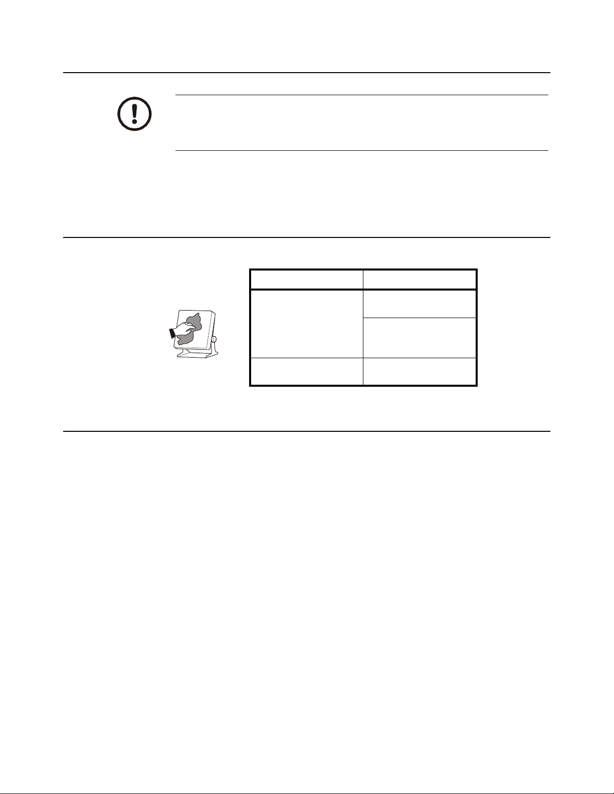
1.5 Cleaning the machine
Table 1.1 Cleaning DOs and DON’Ts
1.4 Routine maintenance
DO DO NOT
1.6 Training
Wipe down the outside of
standard products with a
clean cloth, moistened with
water and a small amount of
mild detergent
Spray the cloth when using a
proprietary cleaning fluid
Do not attempt to operate or complete any procedure on a machine unless you have
received the appropriate training or read the instruction books.
To avoid the risk of RSI (Repetitive Strain Injury), place the machine on a surface which
is ergonomically satisfactory to the user. Take frequent breaks during prolonged usage.
Attempt to clean the inside of
the machine
Use harsh abrasives,
solvents, scouring cleaners
or alkaline cleaning solutions
Spray any liquid directly on to
the display windows
7821 User Instructions 7
Page 8
General information and warnings
1.7 FCC and EMC declarations of compliance
United States
This equipment has been tested and found to comply with the limits for a Class A digital
device, pursuant to Part 15 of the FCC Rules. These limits are designed to provide
reasonable protection against harmful interference when the equipment is operated in a
commercial environment. This equipment generates, uses, and can radiate radio frequency
energy and, if not installed and used in accordance with the instruction manual, may cause
harmful interference to radio communications. Operation of this equipment in a residential
area is likely to cause harmful interference in which case the user will be required to correct
the interference at his own expense.
Canada
This digital apparatus does not exceed the Class A limits for radio noise emissions from
digital apparatus set out in the Radio Interference Regulations of the Canadian Department
of Communications.
Le présent appareil numérique n’émet pas de bruits radioélectriques dépassant les limites
applicables aux appareils numériques de la Classe A prescrites dans le Règlement sur le
brouillage radioélectrique edicté par le ministère des Communications du Canada.
European Countries
WARNING: This is a Class A product. In a domestic environment, this product may cause
radio interference in which the user may be required to take adequate measures.
8 7821 User Instructions
Page 9

2 Specifications
Capacity/Resolution
Model Capacity (lb) Capacity (kg) Divisions
7821-70 150 x 0.05 lb
7821-75 150 x 0.02 lb
7821-100 200 x 0.05 lb
60 x 0.02 kg
70 x 0.02 kg
75 x 0.02 kg
75 x 0.01 kg
-
100 x 0.02 kg
3000d
3500d
3750d
7500d
4000d
5000d
Approvals
Model 7821-70, 7821-75 and 7821-100
USA: NTEP COC #95-070
Canada: Ministry of Industry #AM5076
Zero Window
Initial automatic zero setting is ±10% of maximum capacity—active at power up.
Manual zero setting range is ±2% of maximum capacity—active using the ZERO key.
Transformer Voltage
Input: 120 VAC +10%, -15% Standard 3 wire w/ground
Output: 15 VDC @.3 Amps DC minimum
Frequency
60 Hz Standard
Power Requirements
0.1 amp maximum
7821 User Instructions 9
Page 10

Unpacking and Installing the Scale
3 Unpacking and Installing the Scale
Unpacking the Scale
1. Remove contents of the shipping container.
2. Inspect the scale for evidence of shipping damage. Immediately report any
damage to the shipper.
Installing the Scale
Mount the scale on a stable, level surface that is free from air currents and vibration.
Be sure the scale platter does not touch any adjacent surfaces.
Cutout Dimensions
To install the scale surface flush with a countertop, use these dimensions to guide your
construction:
7821 Platform Minimum Cutout
Dimensions
14" (35.6cm) W x 14.75" (37.5cm) W x
12.5" (31.7cm) L 13.25" (33.7cm) L
4.1" (10.4cm) Min Ht.
adjustable to 4.6" (11.7cm)
Dimensions
Attaching VelcroTM Fasteners (optional)
For the optional remote display, attach Velcro™ fasteners to both the back of the
display and to the surface where the display is to be mounted. To attach the Velcro
fasteners, clean the mounting areas thoroughly and press the Velcro into place. The
adhesive adheres best to a smooth, clean surface.
Velcro is a registered trademark of Velcro USA, Inc.
10 Product Name Manual Type
Page 11

4 Operation
4.1 Power Up Test Sequence
When the scale is first powered up, it will perform a test sequence. During this
sequence, the display will show the following:
l The model number and software revision level
l A numeric counting test for all segments of the display
If everything is OK, the display will show zero weight and the scale is ready for use. If
an error was detected, it will be reported by an error code as described in the section
Error Codes. If the scale is outside the ± 10% zero window, center dashes are displayed
- - - - -. Recalibration may be required.
4.2 Performing a Normal Weighment
1. With the scale powered on, make sure the scale platter is empty and the display is
at zero. If it not, press the
ZERO key …
4.1 Power Up Test Sequence
0.00 is displayed.
2. Place an item to be weighed on the scale platter …
The scale will display the gross weight.
3. Remove the item from the scale platter.
7821 User Instructions 11
Page 12

Modes of Operation
1
1
2
2
OPEN
OPEN
3
3
4
4
N/A
Internal/External Keys
Gravity Setting
Menu
Top view of 7821 with
platter removed.
5 Modes of Operation
5.1 Accessing the Menu
The 7821 powers up in normal weighing mode ready for weighing operations. Access
the Menu Mode by setting Switch 1 shown in Figure 5.1 to the OPEN or MENU Mode
position.
There are three modes available to you with Switch 1 in the MENU Mode or OPEN
position. They are as follows:
Diagnostic Mode Used to test areas of the scale’s function
Configuration ModeUsed to configure the scale for your application
Calibration Mode Used when calibrating the scale
The structure for these menus is shown in Figure 5.2. The following pages have specific
information about each mode and step-by-step instructions for accessing them.
5.1.1 Zero and Units Key
The ZERO key zeros the scale, and UNITS key changes the unit of measure between
lb and kg.
Figure 5.1 7821 Switch Location
12 7821 User Instructions
Page 13

5.1.2 Display
CAPACITY:
POSTAL WEIGHT CLASSIFIER
lb/oz
ZERO
RANGE IN US E
W1
W2
lb
UNITS
5.1.3 Remote Display
The NCI 7821 bench scale has an optional remote display. Typically, the remote display
is used to display weight only (i.e., the
Alternatively, it is possible to have operable
but in so doing, the keys must be disabled on the local (or internal) display. To activate
ZERO and UNITS keys on the remote display, set dip Switch 3 to the OPEN position.
the
5.2 Gravity Adjustment
5.2 Gravity Adjustment
ZERO and UNITS keys are not operable).
ZERO and UNITS keys on the remote display,
With Switch 2 set to OPEN, you can adjust the local gravity value. Press the ZERO key
to increase the value or press the
UNITS key to decrease the value. See Gravity Mode
on page 22 for details.
7821 User Instructions 13
Page 14

Modes of Operation
Norm al W eighing
Mode
Set Switch 1 to
the OPEN Position
Set Switch 2 to
the O PEN P osition
Menu Mode
DIAG CONF
9.xxxx
FILT
SLO
DISP RA RO I/0 HRESA HRE SN LOC-G DONE
BAUD
Performs a
display test
Performs a
te st o f R AM
Performs a
te st o f R OM
Pe rfo rm s a
input/output
te s t
Performs a
division test
w/AZT
CAL-G
Dis plays the
c alib ration
gravity value
Performs a
division test
w/o AZT
Displays the
current
gravity v alue
CAL
LBS
U ON
FAST
1000G
U OF F
CLASS
Scale capac it y is prompt ed.
See Table 5. 1 f or t he list of
alternat ive weight available
for dif ferent capacit ies .
If scale is placed in noisy
envir onment , set slow
filter to minimize the effects.
SCALE
LOAD 0
LOAD
(CAP)
DONE
To increas e local gr avit y set t ing,
press and hold key .ZERO
To decreas e value, press and
hold the key .UNITS
Return S wit c h 2 t o CLO S ED posit ion when done.
150-1
60.02
150-2
70.02
150-3
75.02
150-4
75.01
200 lb
kg
100. 02
PROT
8213 3835NCI
DONE
Choose f r om a list
of 12 baud and
parit y opt ions
See Table 5. 2
Indicates Factory
Default Settings
Press the key to move in the menuZERO
Press the key to move in the menuUNIT S
Af t er making a selec t ion, t he display generally
moves t o the next paramet er in t he lis t .
Af t er choosing done, t he dis play s hows DIAG .
The NCI 7821 bench scale allows calibration of the scale using less than full capacity
weights. The following tables show alternative weights that can be used to calibrate the
scale at its designated capacity. See Table 1 for alternate calibration span loads.
Figure 5.2 Menu structure
14 7821 User Instructions
Page 15

5.2.1 Alternative Calibration Span Points
Table 5.1 Alternative Calibration Span Points
5.2 Gravity Adjustment
Alternative
Capacity lbs
150 x 0.05 lb 10, 50, 150
150 x 0.02 lb 10, 50, 150 75 x 0.01 kg 10, 30, 75
200 x 0.05 lb 10, 100, 200 100 x 0.02 kg 10, 50, 100
Calibration
Weights (lbs)
5.2.2 Baud Rate and Parity Options
Table 5.2 Baud Rate and Parity
Options
Display Baud Parity
12 E 1200 Even
48 E 4800 Even
*96 E 9600 Even
192 E 19,200 Even
12 o 1200 Odd
48 o 4800 Odd
96 o 9600 Odd
192 o 19,200 Odd
12 n 1200 None
48 n 4800 None
96 n 9600 None
192 n 19,200 None
Capacity (kg)
60 x 0.02 kg
70 x 0.02 kg
75 x 0.02 kg
Alternative
Calibration
Weights (kg)
10, 30, 60
10, 30, 70
10, 30, 75
*Factory Default Setting
7821 User Instructions 15
Page 16

Modes of Operation
5.2.3 Scale lb/kg Capacity and Count-by Choices
Table 5.3 Scale lb/kg Capacity and Count-by
Choices
Capacity (lb) Capacity (kg)
150 - 1 150 x 0.05 60 x 0.02
150 - 2 150 x 0.05 70 x 0.02
150 - 3 150 x 0.05 75 x 0.02
150 - 4 150 x 0.02 75 x 0.01
200 200 x 0.05 100 x 0.02
5.3 Diagnostics Mode
The Diagnostic (DIAG) Mode menu lets you test specific areas of the scale’s function.
These areas are:
Display (DISP)
Shows the version and revision of the software, followed by a display segment test.
RAM (RA)
Performs a nondestructive test of RAM in the processor. Displays PASS or FAIL.
ROM (RO)
Performs a checksum of all locations of ROM in the processor. Displays PASS or FAIL.
Input/Output (I/O)
Data is output by the scale, and through the use of a loopback connector, the data is
immediately read back into the receive channel and verified against what was sent.
PASS or FAIL is displayed. Requires a jumper (short) between transmit and receive
data lines.
Division, Test w/AZT (HRESA)
Weight data is normalized to 100,000 counts of displayed resolution. AZT is enabled.
Typically used by service technicians.
Division, Test w/o AZT (HRESN)
Weight data is normalized to 100,000 counts of displayed resolution. AZT is disabled.
Typically used by service technicians.
16 7821 User Instructions
Page 17

5.3.1 Step-by-Step Instructions for DIAG Mode
Press the ZERO key to scroll through lists of selections.
Press the UNITS key to make a selection.
If you want to skip a test, press the ZERO key to scroll to the next test.
DIAG will flash every 10 seconds during the high resolution test to remind you that
you are doing a test and not seeing normal weight readings.
Follow these steps to access the tests in the DIAG menu.
1. From normal weighing mode, move Switch 1 to the MENU Mode or OPEN
position. (See Figure 1).
DIAG is displayed.
2. Press the UNITS key …
DISP is displayed. This stands for display.
5.3 Diagnostics Mode
3. Press the UNITS key to perform the display test described earlier …
Display test is performed and the display shows DISP after the test is
completed.
4. Press the ZERO key …
RA is displayed. This stands for the RAM test.
5. Press the UNITS key to perform the RAM test …
PASS or FAIL is displayed briefly, then DISP. If the test fails, contact
your local Avery Weigh-Tronix distributor for service.
6. Press the ZERO key to scroll to the ROM test …
RO is displayed. This stands for the ROM test.
7. Press the UNITS key to perform the ROM test …
PASS or FAIL is displayed. If the test fails, contact your local Avery
Weigh-Tronix distributor for service.
8. Press the ZERO key to scroll to the I/O test …
I/O is displayed. This stands for the Input/Output test.
9. With a loopback connector in place, press the UNITS key to perform the I/O
test …
PASS or FAIL is displayed. If the test fails, check your connections and/
or contact your local Avery Weigh-Tronix distributor for service.
10. Press the ZERO key …
HRESA is displayed. This stands for the high resolution test with AZT
enabled.
7821 User Instructions 17
Page 18

Modes of Operation
11. Press the UNITS key to perform this test …
The display shows the weight on the scale at a resolution of 100,000
counts.
12. Press the UNITS key to stop the test …
HRESA is displayed.
13. Press the ZERO key …
HRESN is displayed. This stands for the high resolution test without AZT
enabled.
14. Press the UNITS key to perform this test …
The display shows the weight on the scale at a resolution of 100,000
counts.
15. Press UNITS key to stop the test …
HRESN is displayed.
16. Press the ZERO key …
LOC-G is displayed. This stands for local gravity or current gravity
setting.
17. Press the UNITS key …
The local or current gravity setting is displayed.
18. Press the ZERO key …
CAL-G is displayed. This stands for calibration gravity setting.
19. Press the UNITS key …
The calibration gravity setting is displayed.
20. When you are finished, press the ZERO key, which displays DONE, and press
the UNITS key, DIAG is displayed, or place Switch 1 back to the closed
position to return back to normal weighing mode.
18 7821 User Instructions
Page 19

5.4 Configuration Mode
The Configuration (CONF) Mode menu allows configuration of the scale to the specific
application need. The items you can configure are as follows:
Filtering (FILT)
Choose between FAST and SLO filtering. Slow should be chosen in areas susceptible
to vibration. Choose FAST filtering for more stable conditions.
Baud (BAUD)
Choose a baud and parity from table.
Protocol (PROT)
Select the communication protocol to be used on the RS-232 or USB VCP port. Only
one protocol & port can be used at a time.
NCI - Ref. 8408-14788-01
W, S, Z, H, U, M Only)
8213 - Ref. 8408-14788-03
3835 - Ref. 8408-14788-12
5.4 Configuration Mode
5.4.1 Step-by-Step Instructions for CONF Mode
Follow these steps to access and configure the items in the CONF menu. Refer to
Figure 5.2.
1. From the normal weighing mode, move Switch 1 to Menu Mode or OPEN
position, then press the ZERO key repeatedly until …
CONF is displayed.
2. Press the UNITS key …
FILT is displayed. This stands for filtering.
3. Press the UNITS key …
The current setting, FAST or SLO, is displayed.
4. Use the ZERO key to toggle between the two choices. Press the UNITS key
when the choice you want is displayed …
The choice is accepted and the display shows FILT.
5. Press the ZERO key …
BAUD is displayed.
6. Press the UNITS key …
The current baud and parity choice is displayed.
7. Use the ZERO key to scroll the choices found in Table 5.2. When the choice
you want is displayed, press the UNITS key …
The choice is accepted and the display shows BAUD.
7821 User Instructions 19
Page 20

Modes of Operation
8. Press the ZERO key …
9. Press the UNITS Key …
10. Use the ZERO key to scroll between the three protocol choices. When the
protocol you want is displayed, press the UNITS key …
11. When finished configuring the scale, press the ZERO key, which displays
DONE, then press the UNITS key, DIAG is displayed, or place Switch 1 back
to the closed position to return back to normal weighing mode.
5.5 Calibration Mode
The Calibration (CAL) Mode menu allows scale calibration. The items in the Calibration
menu are as follows:
PROT is displayed.
The current protocol is displayed.
The choice is accepted and the display shows PROT.
Pounds/Kilograms (lb or 1000G)
Selects the unit of measure of your calibration test weights.
Scale or Class
When calibrating the scale for lb, calibrate the unit as a SCALE or as a CLASS (weight
classifier/postal rounding).
U On / U Off
When configured for U ON, the scale will allow switching between lb/kg using the
UNITS key.
Capacity (100, etc.)
Selects the capacity of the scale.
5.5.1 Step-by-Step Instructions for CAL Mode
Follow these steps to calibrate the scale. Refer to Figure 5.2.
1. From normal weighing mode, move Switch 1 to the Menu Mode or OPEN
position …
DIAG is displayed. Press the ZERO key until CAL is displayed.
20 7821 User Instructions
Page 21

5.5 Calibration Mode
2. 2.Press the UNITS key to start calibration …
LBS or 1000G (kg) is displayed.
WARNING! Entering this mode can erase the calibration already saved. Special
calibration weights are needed to use calibration mode.
3. Press the ZERO key to toggle between the choices of unit of measure (lb or
kg). When the choice you want is displayed, press the UNITS key to accept …
The choice is accepted and U ON is displayed.
4. Press the ZERO key to toggle between the choices U ON or U OFF. Once your
choice is displayed, press the UNITS key. See above for the definitions of
calibrating the scale using U ON or U OFF.
5. If LB was chosen for calibration, the scale will display SCALE. Press the
ZERO key to toggle between SCALE and CLASS. Press the TEST key. If kg
was chosen, this step is skipped. The scale then prompts one of the capacities
from Table 5.3.
6. Press the ZERO key to toggle between the capacity choices. When the choice
you want is displayed, press the UNITS key …
The scale prompts LOAD 0.
7. Clear all weight from the scale platter and press the UNITS key …
After a brief pause, LOAD xxx is displayed
(xxx = Span Weight).
Alternate calibration points can be chosen using the TEST key to toggle
between choices (see Table 5.1).
If no span weight is applied, calibration will be aborted. CAL ERROR ABORT will be
displayed.
8. Place chosen span calibration weight on the scale and press the UNITS key …
After a brief pause, DONE is displayed. The scale then prompts DIAG.
9. Remove all calibration weights from scale.
10. Return Switch 1 to the closed position …
The scale returns to normal weighing mode.
The scale is now tested, configured and calibrated. It is ready for use in your
application.
7821 User Instructions 21
Page 22

Modes of Operation
5.6 Gravity Mode
The Gravity Mode feature provides a means of adjusting the scale’s internal calibration
factors to compensate for variations in acceleration due to gravity at different
geographic locations. These differences can cause a given mass to indicate a slightly
different weight at an end-user’s (local) site than it did at the Calibration (CAL) site.
WARNING: Using this feature in “sealed” applications may be subject to
approval by the appropriate governing agency at the end-users site.
Gravity value roles over at 9.8400 and rolls under at 9.7700.
To make the adjustment, you must know the value of the gravity constant for the local
site. This value is expressed in meters per second, per second (i.e., m/s2). It is not
necessary to calibrate the scale, therefore, no calibration weights are needed to make
this adjustment.
The scale maintains two gravity setting values. The first is the “calibration-site” value
known as CAL-G. The second is the end-user or “local-site” value and is known as
LOC-G. When the scale was originally calibrated at the factory, the CAL-G and LOC-G
values were both set to 9.8040 which is the gravity constant for the manufacturing site.
To adjust the displayed weight value to accurately reflect an applied test weight, you
can either recalibrate the scale or adjust the local gravity setting.
To view the calibration or local gravity values, you must access the DIAG menu and
scroll to LOC-G or CAL-G message and press the UNITS key.
To view or adjust the Local Gravity value, set Switch 2 to the OPEN position. The
display will indicate the current “local” gravity value. Press the ZERO key to increment
the value or the UNITS key to decrement the value. The gravity value will change in
steps of .0002. When the correct value is displayed, return Switch 2 to the CLOSED
position. The scale will now use this new relationship between calibration and local
gravity for its weight calculations.
22 7821 User Instructions
Page 23

6 Communication
RS232
USB HID
Remote Display
USB VCP
6.1 Interface Cable
The 7821 scale comes factory configured with one communication port, however the
data can be transfered out of the base using one of the following interface devises:
1 serial RS232, 1 USB VCP or 1 USB HID
Only one of these interface devises can be used from the scale at a time.
6.1 Interface Cable
RS232
There is one 9-pin DE type female connector accessible at the rear of the unit. The
functional pinout of this cable is that of a standard PC which is as follows:
DE-9 Female Scale DE-9 Male Host
Pin Name Direction Pin Name Direction
1. JMP 1 - 1. DCD IN
2. TXD OUT 2. RXD IN
3. RXD IN 3. TXD OUT
4. JMP 1 - 4. DTR OUT
5. SG - 5. GRD -
6. JMP 1 - 6. DSR IN
7. JMP 2 - 7. RTS OUT
8. JMP 2 - 8. CTS IN
9. NC - 9. RI IN
Scale baud and parity needs to be set to the default setting 96E (baud 9600, Parity:
even) as shown in Baud Rate and Parity Options on page 19.
7821 User Instructions 23
Page 24

Communication
USB VCP
Allows the base to connect directly to PC using the USB port connection.
PC USB port still needs to be setup to match scale b aud rate communications.
Scale baud and parity needs to be set to the default setting 96E (baud 9600, Parity:
even) as shown in Baud Rate and Parity Options on page 15.
Driver required when connected to a PC. Download driver from the password
protected portion of www.averyweigh-tronix.com.
USB HID
Used to connect to a dedicated PC terminal where the Avery Weigh-Tronix OPOS or
UPOS (POS.NET) drivers have been integerated into a 3
Once a computer is connected to the USB HID port, the RS232 and USB VCP ports
will be inactive until the computer is disconnected and power is cycled on the scale.
rd
party software application.
The Baud should be set to 9600, Even Parity and the Protocol needs to be set to NCI.
6.2 Serial Communications Protocol
For command/response descriptions, please refer to the following Avery Weigh-Tronix
NCI Serial Communications Documents:
NCI Standard Protocol: 8408-14788-01 (W, S, Z, H, U, M only)
8213 Protocol: 8408-14788-03
NCI 3835 Protocol: 8408-14788-12
24 7821 User Instructions
Page 25

6.3 NCI Communications Protocol
This standard is used by all NCI bench scale products.
SYMBOL KEY:
<ETX> End of text character (Ø3 hex)
<LF> Line feed character (ØA hex)
<CR> Carriage return character (ØD hex)
<SP> Space (2Ø hex)
x Character from display including minus sign.
hh Two status bytes
uu Unit of measure (lb, kg, oz, g, etc. using ANSI standard abbreviations)
W<CR>
Scale Response
<LF>xxxx.xxuu<CR>
<LF>hh...<CR><ETX>
Results
Returns decimal weight, units, plus scale status
6.3 NCI Communications Protocol
S<CR>
Scale Response
<LF>hh…<CR><ETX>
Results
Returns scale status.
Z<CR>
Scale Response
<LF>hh…<CR><ETX>
Results
Scale is zeroed, returns status.
H<CR>
Scale Response
<LF>xxxx.xxuu<CR>
<LR>hh...<CR><ETX>
Results
Returns decimal weight in 10x with units plus scale status.
7821 User Instructions 25
Page 26

Communication
U<CR>
Scale Response
<LF>uu<CR><ETX>
Results
Changes unit of measure, returns new units.
M<CR>
Scale Response
<LF>xxxxxxxMM<CR>
<LF>hh...<CR><ETX>
Results
Returns normalized raw counts and count status.
All other commands
Scale Response
<LF>?<CR><ETX>
Results
Unrecognized command
26 7821 User Instructions
Page 27

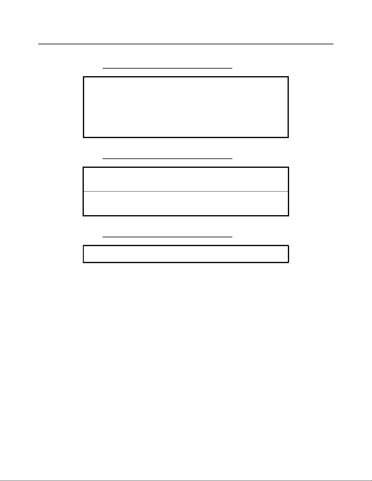
7 Error Codes and Troubleshooting
842 1
Calibra tio n e rror (E-01
ROM error (E-02)
RAM error (E-04)
Se rial EE (E-08)
842 1
Rese rved for
Future Use
Any system errors detected by the scale will be displayed as the letter E followed by a
two-digit error code. Press the UNITS key to continue operation. If a calibration error
occurs, the only way to clear it is by recalibrating the scale.
The error codes are broken down into two hexadecimal numbers, with each bit defining
a single error condition. The error codes are defined as follows:
7821 User Instructions 27
Page 28

Error Codes and Troubleshooting
7.1 Troubleshooting
Perform the following steps in the order presented until the described problem is
corrected. If the problem cannot be corrected, contact your Avery Weigh-Tronix service
provider.
No Power (Display is Blank)
1. Check that the primary side of the cord is plugged into the AC outlet, and the
secondary side is properly connected to the power jack on the back of the scale.
2. Replace the power supply.
Missing or extra segments on display
1. Replace the display board.
Scale will not return to zero, or incorrect weight is displayed
1. Press the ZERO key.
2. Check for interference of weighing platform.
3. Power off, remove all items from the platter, and then power on the scale.
4. Recalibrate the scale.
Display shows unrecognized characters
1. Power down, then power up the scale.
2. Check software PROM for proper insertion.
3. Check display cables for the proper connection.
Display shows under _ _ _ _ _ dashes
(Indicates that the scale is below zero or under capacity.)
1. Verify that weigh platter is on the scale.
2. Verify that nothing is interfering with or rubbing against the weighing surface.
3. Press the ZERO key.
4. Power down, then power up the scale.
5. Recalibrate the scale.
28 7821 User Instructions
Page 29

Display shows center - - - - - dashes
(Indicates that the scale is outside zero capacity of ±2%.)
1. Verify that weigh platter is on the scale.
2. Press the ZERO key.
3. Power down, then power up the scale.
4. Recalibrate the scale.
7.1 Troubleshooting
Display shows upper
(Indicates the scale is over capacity.)
1. Remove all items from the scale.
2. Press the ZERO key.
3. Power down, then power up the scale.
4. Recalibrate the scale.
_ _ _ _
dashes
Scale is not transmitting data to the host device
1. Check cable connection at both the rear of the scale and the host device.
2. Check communication setting and baud rate on both scale and software.
3. Perform I/O loopback test.
4. Replace the main PC board.
The ZERO key and the UNITS key do not function
1. Replace the display panel.
2. Replace the display PCB.
3. Replace the main PCB.
7821 User Instructions 29
Page 30

Spare parts
8 Spare parts
Description Part Number
Keyboard Panel AWT25-501980
Display PCB 7405-15465
Loadcell (100kg) 7154-16335-100
Main PCB 7405-14704-2
Power Supply 1148-15536
RS-232 Cable 1140-13842
30 7821 User Instructions
Page 31

Page 32

Avery Weigh-Tronix USA
1000 Armstrong Dr.
Fairmont MN 56031 USA
Tel: 507-238-4461
Fax: 507-238-4195
Email: usinfo@awtxglobal.com
www.averyweigh-tronix.com
Avery Weigh-Tronix UK
Foundry Lane,
Smethwick, West Midlands,
England B66 2LP
Tel: +44 (0) 8453 66 77 88
Fax: +44 (0)121 224 8183
Email: info@awtxglobal.com
www.averyweigh-tronix.com
 Loading...