

Page 1

Model 7800 Family
Weight Classifiers
User Instructions
AWT35-501540
Issue AA
Page 2

Avery Weigh-Tronix is a trademark of the Illinois Tool Works group of companies whose ultimate parent company is
Illinois Tool Works Inc (“Illinois Tool Works”). Copyright © 2016 Illinois Tool Works. All rights reserved.
No part of this publication may be reproduced by making a facsimile copy, by the making of a copy in three dimensions of a two-dimensional
work and the making of a copy in two dimensions of a three-dimensional work, stored in any medium by electronic means, or transmitted in
any form or by any means, including electronic, mechanical, broadcasting, recording or otherwise without the prior written consent of the
copyright owner, under license, or as permitted by law.
This publication was correct at the time of going to print, however Avery Weigh-Tronix reserves the right to alter without notice the
specification, design, price or conditions of supply of any product or service at any time.
7800family_u_en_501540.book Issue Draft of AA
Page 3

Table of Contents
page
Table of Contents ...................................................................................................................................... 3
Chapter 1 General information and warnings ......................................................................................... 5
About this manual ..............................................................................................................5
Text conventions ......................................................................................................... 5
Special messages ....................................................................................................... 5
Installation .......................................................................................................................... 6
Electrical installation .......................................................................................................... 6
Pluggable equipment ................................................................................................... 6
Wet conditions ............................................................................................................. 6
Routine maintenance ......................................................................................................... 7
Cleaning the machine ........................................................................................................ 7
Training .............................................................................................................................. 7
FCC and EMC declarations of compliance ........................................................................ 8
Chapter 2 Specifications ........................................................................................................................... 9
Chapter 3 Initial Setup ............................................................................................................................. 12
Unpacking the Scale ........................................................................................................ 12
Installing the Scale ...........................................................................................................12
Chapter 4 Operation ................................................................................................................................ 14
Power Up Test Sequence ................................................................................................ 14
Performing a Normal Weighment ..................................................................................... 14
Operation Controls ........................................................................................................... 15
Chapter 5 Accessing the Menu Mode .................................................................................................... 16
Accessing the Gravity Mode ............................................................................................ 16
Menu Mode ......................................................................................................................16
Gravity Mode .................................................................................................................... 18
Alternative Calibration Points ........................................................................................... 18
Baud Rate and Parity Options ......................................................................................... 19
Diagnostic (DIAG) Mode .................................................................................................. 19
Configuration Mode .......................................................................................................... 23
Print Modes ...................................................................................................................... 25
Calibration Mode .............................................................................................................. 26
Step-by-Step Instructions for CAL Mode ................................................................... 26
Gravity Mode .................................................................................................................... 27
Re-Calibration Mode ........................................................................................................ 28
Step-by-Step Instructions for RE-CAL mode ............................................................. 28
Review/Test Scale Settings ............................................................................................. 29
Chapter 6 Communication ...................................................................................................................... 31
Communications Enabled ................................................................................................ 32
Interface Cable Specifications ......................................................................................... 33
NCI Serial Communications Protocol ............................................................................... 33
Standard Commands ....................................................................................................... 33
Optional Commands ........................................................................................................ 34
Chapter 7 Error Codes and Troubleshooting ........................................................................................ 35
Troubleshooting ............................................................................................................... 35
Chapter 8 Spare parts ............................................................................................................................. 38
7800 Family User Instructions 3
Page 4

4 7800 Family User Instructions
Page 5

1 General information and warnings
1.1 About this manual
This manual is divided into chapters by the chapter number and the large text at the top
of a page. Subsections are labeled as shown by the 1.1 and 1.1.1 headings. The
names of the chapter and the next subsection level appear at the top of alternating
pages of the manual to remind you of where you are in the manual. The manual name
and page numbers appear at the bottom of the pages.
1.1.1 Text conventions
Key names are shown in bold and reflect the case of the key being described. This
applies to hard keys and on-screen or soft keys.
Displayed messages appear in bold italic type and reflect the case of the displayed
message.
1.1 Text conventions
1.1.2 Special messages
Examples of special messages you will see in this manual are defined below. The
heading words have specific meanings to alert you to additional information or the
relative level of hazard.
ELECTRICAL WARNING!
THIS IS AN ELECTRICAL WARNING SYMBOL.
ELECTRICAL WARNINGS MEAN THAT FAILURE TO FOLLOW
SPECIFIC PRACTICES OR PROCEDURES MAY RESULT IN
ELECTROCUTION, ARC BURNS, EXPLOSIONS OR OTHER HAZARDS
THAT MAY CAUSE INJURY OR DEATH.
CAUTION!
This is a Caution symbol.
Cautions give information about procedures that, if not observed, could result
in damage to equipment or corruption to and loss of data.
NOTE: This is a Note symbol. Notes give additional and important information, hints
and tips that help you to use your product.
7800 Family User Instructions 5
Page 6
1.2 Installation
DANGER: RISK OF ELECTRICAL SHOCK. NO USER SERVICEABLE
PARTS. REFER TO QUALIFIED SERVICE PERSONNEL FOR SERVICE.
CAUTION: Installation, configuration, and servicing are only to be done by
qualified service personnel as authorized by Avery Weigh-Tronix.
1.3 Electrical installation
CAUTION: The power cable must be connected to an earth-grounded electrical
outlet. The electrical supply must have a circuit breaker with an appropriate
rating to protect from over-current conditions.
For your protection, all electrical (110V or 230V) equipment used out of doors or
in wet or damp conditions should be supplied from a correctly fused power
source and protected by an approved ground fault protection device (RCD,
GFCI etc.)
IF IN DOUBT SEEK ADVICE FROM A QUALIFIED ELECTRICIAN.
1.3.1 Pluggable equipment
Pluggable equipment must be installed near an easily accessible socket outlet.
1.3.2 Wet conditions
Under wet conditions, the plug must be connected to the final branch circuit via an
appropriate socket / receptacle designed for washdown use.
Installations within the USA should use a cover that meets NEMA 3R specifications
as required by the National Electrical Code under section 410-57. This allows the unit
to be plugged in with a rain tight cover fitted over the plug.
Installations within Europe must use a socket which provides a minimum of IP56
protection to the plug / cable assembly. Care must be taken to make sure that the
degree of protection provided by the socket is suitable for the environment.
6 7800 Family User Instructions
Page 7
1.4 Routine maintenance
IMPORTANT: This equipment must be routinely checked for proper operation
and calibration.
Application and usage will determine the frequency of calibration required for
safe operation.
Always turn off the machine and isolate from the power supply before starting any
routine maintenance to avoid the possibility of electric shock.
Make sure that it is placed securely on a flat and level surface.
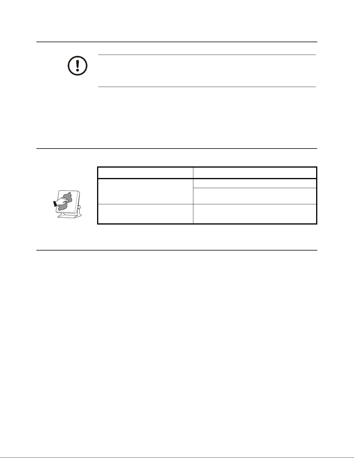
1.5 Cleaning the machine
Table 1.1 Cleaning DOs and DON’Ts
DO DO NOT
1.4 Wet conditions
1.6 Training
Wipe down the outside of standard products
with a clean cloth, moistened with water and
a small amount of mild detergent
Spray the cloth when using a proprietary
cleaning fluid
Do not attempt to operate or complete any procedure on a machine unless you have
received the appropriate training or read the instruction books.
To avoid the risk of RSI (Repetitive Strain Injury), place the machine on a surface which
is ergonomically satisfactory to the user. Take frequent breaks during prolonged usage.
Attempt to clean the inside of the machine
Use harsh abrasives, solvents, scouring cleaners or
alkaline cleaning solutions
Spray any liquid directly on to the display windows
7800 Family User Instructions 7
Page 8
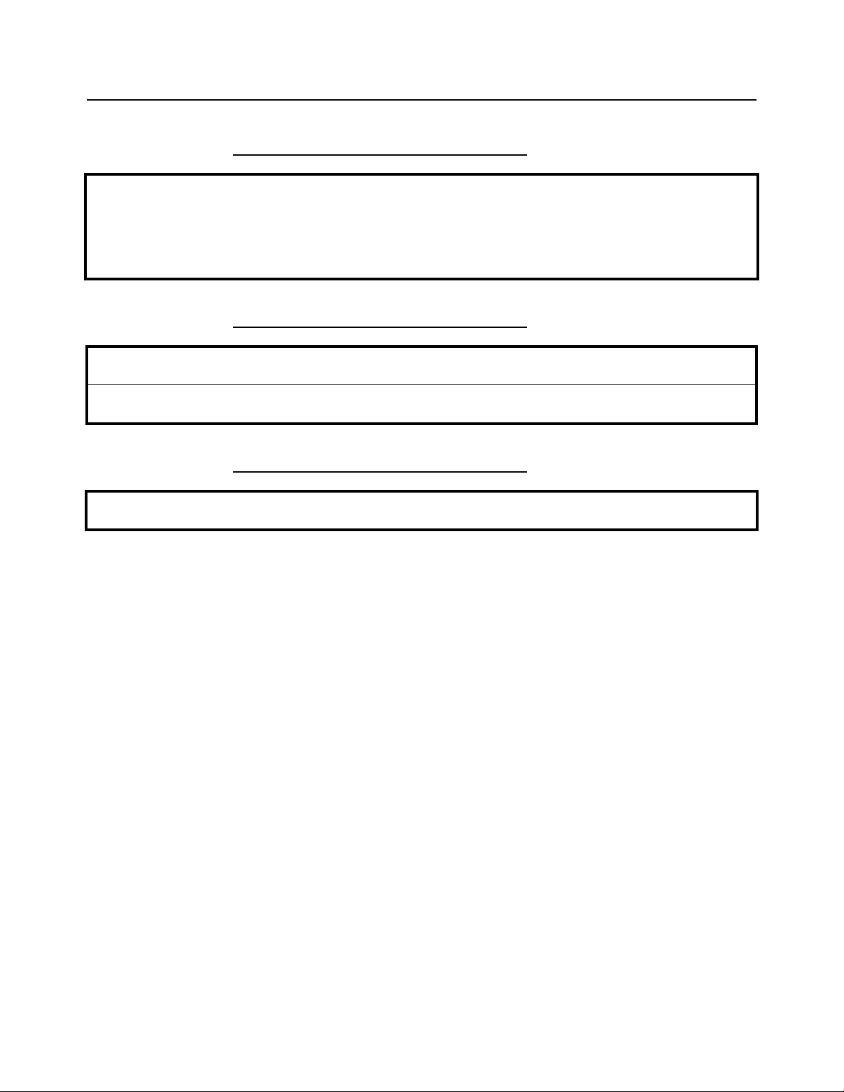
1.7 FCC and EMC declarations of compliance
United States
This equipment has been tested and found to comply with the limits for a Class A digital device, pursuant to Part 15 of the FCC Rules.
These limits are designed to provide reasonable protection against harmful interference when the equipment is operated in a
commercial environment. This equipment generates, uses, and can radiate radio frequency energy and, if not installed and used in
accordance with the instruction manual, may cause harmful interference to radio communications. Operation of this equipment in a
residential area is likely to cause harmful interference in which case the user will be required to correct the interference at his own
expense.
Canada
This digital apparatus does not exceed the Class A limits for radio noise emissions from digital apparatus set out in the Radio
Interference Regulations of the Canadian Department of Communications.
Le présent appareil numérique n’émet pas de bruits radioélectriques dépassant les limites applicables aux appareils numériques de
la Classe A prescrites dans le Règlement sur le brouillage radioélectrique edicté par le ministère des Communications du Canada.
European Countries
WARNING: This is a Class A product. In a domestic environment, this product may cause radio interference in which the user may be
required to take adequate measures.
8 7800 Family User Instructions
Page 9

2 Specifications
Description
The NCI 7800 models are digital electronic parcel bench scales specifically designed
for shipping applications and are Legal-for-Trade. The scales have built-in intelligence
that enables them to be easily interfaced with a computer or other data-processing
device.
Capacity/Resolution
Model Capacity (lb) Capacity (kg) n(max)
7820-50
7820-70
7820-75
7880-50
7880-75
7880-125
7880-150
7885-75 150 x 0.05 lb 75 x 0.02 kg 3750d
7829-125 250 x 0.05 lb 100 x 0.02 kg 5000d
7840-125
7840-150
7824-125
7824-150
100 x 0.02 lb
150 x 0.05 lb
150 x 0.02 lb
100 X 0.02 lb
150 x 0.05 lb
250 x 0.05 lb
300 x 0.1 lb
250 x 0.05 lb
300 x 0.1 lb
250 x 0.05 lb
300 x 0.1 lb
50 x 0.01 kg
60 x 0.02 kg
75 x 0.01 kg
50 x 0.01 kg
75 x 0.02 kg
100 x 0.02 kg
150 x 0.05 kg
100 x 0.02 kg
150 x 0.05 kg
100 x 0.02 kg
150 x 0.05 kg
5000d
3000d
7500d
5000d
3750d
5000d
3000d
5000d
3000d
5000d
3000d
Agency Certificates of Conformance
If unit is to be used as a commercial device, all local reporting and registration
requirements must be followed.
Model 7820
United States: NTEP #95-070
Canada: Ministry of Industry #AM-5076
For use as a Class III device from +5°C through +40°C
Model 7885
United States: NTEP #02-069
Canada: Ministry of Industry (#AM-5507)
For use as a Class III device from +5°C through +40°C
Models 7824, 7829, 7840, 7880
United States: NTEP #95-121
Canada: Ministry of Industry #AM-5099
For use as a Class III device from +5°C through +40°C
7800 Family User Instructions 9
Page 10

Dimensions
Model 7820: 14" L x 12.5" W x 4.1" H
Model 7880: 18" L x 18" W x 4.6" H
Model 7885: 18" L x 18" W x 3.0" H
Model 7829: 20" L x 20" W x 5.3" H
Model 7840: 18" L x 24" W x 4.6" H
Model 7824: 24" L x 24" W x 4.6" H
Power Supply
UL/CSA approved in-line power supply with 6’ line cord. (7885 uses wallmount style)
Input:120 VAC +10%-15%, Standard 3 wire w/ground
Output:15 VDC @.3 Amps DC
Frequency
60 Hz Standard
Power Requirements
0.1 amp maximum
Operating Temperature
42ºF – 104ºF (5ºC – 40ºC)
10% to 95% RH (non-condensing)
Construction
Model 7820: Die cast aluminum base with a stainless steel weigh platter.
Overload protection: Adjustable center stop, fixed corner stops.
Model 7885: Painted mild steel base with stainless steel weigh platter.
Overload protection: Fixed center and corner stops.
Models 7824, 7829, 7840, 7880: Painted mild steel base with stainless steel weigh
platter. Overload protection: Adjustable center and corner stops.
Display
½" high, six-digit LCD. Internal display standard on all models except 7885 (remote
only)
Key panel with ZERO and TEST keys.
Optional remote display with 7 ft. cable.
Scale Leveling
Level bubble located under weigh platter. Adjustable feet in each corner to level the
scale.
10 7800 Family User Instructions
Page 11

Zero Window
Initial automatic zero setting is ±10% of maximum capacity—active at power up.
Manual zero setting range is ±2% of maximum capacity—active using the ZERO key.
Under Capacity Limits
Under capacity indication will be given with dashes appearing on the bottom line of the
display whenever the display is more than 2 percent below the initial zero value.
Over Capacity Limits
Over capacity indication will be given with dashes appearing in the upper line of the
display whenever the weighed item exceeds 9 divisions over the rated capacity of the
unit. The scale will use the Initial zero value for reference for over capacity
determination.
Sealing
Access to the calibration switch can be secured with a lead wire or pressure sensitive
security seal. The remote and primary indicators have no metrological features that
require the use of a security seal.
Internal Counts
The scale has 100,000 internal counts.
Dynamic Response
The time from when weight is applied to the scale until a stable weight display is
displayed:
0–1000d 1.5 seconds
1000d+ 2.0 seconds
maximum mean average
Communications
Factory default settings: 9600 baud, 7 data bits, even parity, 1 stop bit.
Standard 9-pin pass through RS232 interface cable included. Not a null modem.
RS232 bidirectional, configurable 1200 to 19.2K baud. Transmits weight and scale
status whenever ASCII “W” <CR> is sent by a remote device.
USB VCP
USB HID
Only one of these three interface devises (RS232, USB VCP or USB HID) can be used
from the scale at a time.
7800 Family User Instructions 11
Page 12

3 Initial Setup
3.1 Unpacking the Scale
1. Remove contents of the shipping container.
2. Inspect the scale for evidence of shipping damage. Immediately report any
damage to the shipper.
3.2 Installing the Scale
1. Mount the scale on a stable, level surface that is free from air currents and
vibration. Be sure the scale platter does not touch any adjacent surfaces.
2. To install the scale surface flush with a countertop, use the dimensions on the
following page to guide construction.
Model 7820
Scale Dimensions Min. Cut-Out Dimensions
D 12.5 in. (31.7 cm)13.25 in. (33.7 cm)
W 14 in. (35.6 cm)14.75 in. (37.5 cm)
H 4.1 in. (10.4 cm)*
*Adjustable to 4.6 in. (11.7 cm)
Model 7880
Scale Dimensions Min. Cut-Out Dimensions
D 18 in. (45.7 cm)18.75 in. (47.6 cm)
W 18 in. (45.7 cm)18.75 in. (47.6 cm)
H 4.6 in. (11.6 cm)*
*Adjustable to 5.1 in. (12.9 cm)
Model 7885 (RS232 only)
Scale Dimensions Min. Cut-Out Dimensions
D 18 in. (45.7 cm)18.75 in. (47.6 cm)
W 18 in. (45.7 cm)18.75 in. (47.6 cm)
H 3.0 in. (7.6 cm)*
*Adjustable to 3.5 in. (8.9 cm)
Model 7829
Scale Dimensions Min. Cut-Out Dimensions
D 20 in. (50.8 cm)20.75 in. (52.7 cm)
W 20 in. (20.8 cm)20.75 in. (52.7 cm)
H 5.3 in. (13.5 cm)*
*Adjustable to 5.8 in. (14.7 cm)
12 7800 Family User Instructions
Page 13

3.2
Model 7840
Scale Dimensions Min. Cut-Out Dimensions
D 24 in. (61.0 cm)24.75 in. (62.9 cm)
W 18 in. (45.7 cm)18.75 in. (47.6 cm)
H 4.6 in. (11.7 cm)*
*Adjustable to 5.1 in. (12.9 cm)
Model 7824
Scale Dimensions Min. Cut-Out Dimensions
D 24 in. (61.0 cm)24.75 in. (62.9 cm)
W 24 in. (61.0 cm)24.75 in. (62.9 cm)
H 4.6 in. (11.7 cm)*
*Adjustable to 5.1 in. (12.9 cm)
3. Loosen the collars or jam nuts on the leveling feet. Level the scale by using the
level bubble under the scale platter as a guide. Be sure all four feet are in firm
contact with the counter, then tighten all collars and jam nuts.
4. Make sure all power cords, remote display cables, etc., are not touching the
live weighing surface.
5. Plug the unit into an appropriate voltage outlet that is properly grounded.
7800 Family User Instructions 13
Page 14

4 Operation
4.1 Power Up Test Sequence
If RAM or ROM error is reported, you must press the TEST key to acknowledge the
condition. See Error Codes and Troubleshooting on page 35.
When the scale is first powered on, it will perform a test sequence. During this
sequence, the display will show the following:
l The model number and the software revision level.
l A numeric counting test for all segments of the display. During this test, a
test of Random Access Memory (RAM) and a test of Read Only Memory
(ROM) is performed.
4.2 Performing a Normal Weighment
When first powered on, if the scale is outside the ± 10% zero window, center dashes
are displayed, - - - -
If necessary, reapply power to reset the initial zero setting. Refer to Error Codes and
Troubleshooting on page 35 if the problem persists.
If everything is OK, the display will show zero weight and the scale is ready for use.
1. With the scale powered on, make sure the scale platter is empty and the display
is at zero. If it is not, press the ZERO key …
0.00 is displayed.
2. Place an item to be weighed on the scale platter …
The scale will display the gross weight.
3. Remove the item from the scale platter.
14 7800 Family User Instructions
Page 15

Figure 4.1 7815 and 7820 display
CAPACITY:
WEIGHT CLASSIFIER
lb
0
TES T
ZER O
CAPACITY:
WEIGHT
lb
0
TES T
ZER O
kg
lb
WEIGHT
TES T
ZERO
CAPACITY:
0
4.3
4.3 Operation Controls
ZERO Key The ZERO key will zero the scale if weight is stable, and acts as the NO or
SCROLL key in the Menu Mode and as the INCREASE key in the Gravity
Mode.
TEST Key The TEST key can be used to perform the initial power-up test sequence,
recall diagnostic routines, or view the configuration information. This key
also functions as YES or ACCEPT in the Menu Mode and as the
DECREASE key in the Gravity Mode.
Figure 4.2 7824, 7829, 7840 and 7880 display
Figure 4.3 Optional Remote Display
All NCI 7800 bench scales, except the 7885, can have an optional remote display. If a
remote display with keyboard is used, then Switch 3 (shown in Figure 1) determines
which display keyboard is functional.
Switch 3 Settings:
Closed= internal display keys operational
Open= external display keys operational
7800 Family User Instructions 15
The remote display must be connected to the RJ45 port (DISPLAY) prior to power up
to operate properly.
Page 16

5 Accessing the Menu Mode
1
1
2
2
OPEN
OPEN
3
3
4
4
N/A
Internal/External Keys
Gravity Setting
Menu
Top view of 7820 with
platter removed.
12
OPEN
34
The 7800 models power up ready for weighing operations. Access the Menu mode by
setting Switch 1 shown in Figure 5.1 or Figure 5.2 to the OPEN or Menu mode position.
5.1 Accessing the Gravity Mode
Access the Gravity setting mode by setting Switch 2, shown in Figure 5.1 and Figure
5.2, to the OPEN or Gravity mode position.
5.2 Menu Mode
Figure 5.1 7820 switch location
Figure 5.2 7824, 7829, 7840, 7880, 7885 switch location
With Switch 1 in the Menu mode or OPEN position, there are four modes available to
you. They are as follows:
DIAG (Diagnostic Mode) To test areas of the scale’s function
CONF (Configuration Mode) To configure the scale for your application
16 7800 Family User Instructions
CAL (Calibration Mode) To calibrate the scale
RE-CAL (Recalibration Mode) To change resolution and rounding type
Page 17

5.2
Norm al W eighing
Mode
Set Switch 1 to
the OPEN Position
Set Switch 2 to
the O PEN Posit ion
Menu Mode
See not e 1
See not es
See not es
See Note 5
Press keyTEST
DIAG CONF
9.xxxx
FILT
SLO
DISP PROTRA
BAUD
RO
CAP
I/0
TYPE
DIV-A
UNITS LOC-G R
DIV-N
PRT OUT CAL-G R
FILT
DONE
BAUD
Performs a
display test
Displays protocl
s ele ction
Performs a
te st o f R AM
Performs a
te s t of R O M
Displays
capac ity /
resolution
selection
Displays
baud/parity
selection
Pe rfo rm s a
input/output
te s t
Displays
rounding
ty pe
Performs a
division test
w/AZT
Displays
unit of
measure
Displays
th e l oc a l
gravity value
Pe rfo rm s a
division test
w/o AZT
Displays
output print
fo rm at
selection
Displays
the calibration
gravity value
Dis pla y s filter
s ele ction
CAL
LBS
FA ST
1000G
CLASS
Scale capac it y is pr ompt ed.
See Table 1 f or t he list of
alternat ive weight available
for dif ferent capacit ies .
Returns to DIAG mode
If sc ale is placed in nois y
environment , set slow
filt er to minim ize t he ef f ec t s.
SCALE
LOAD 0
LOD
(CAP)
DONE
RE-CAL
ROUNDRESO
150. 02
75.02
150.05
75.01
lb selections
kg selections
CLASS
Indicates Factory
Default Settings
Press the key to move in the menuZERO
Press the key to move in the menuTEST
Af t er making a selec t ion, t he display generally
moves t o the next param et er in t he list .
Af t er choosing done, t he display s hows DIAG .
Notes:
1) T he 're- calibrat ion' values displayed
will be the sam e as those of the
original 'c alibrat ion' unit s of meas ure.
2) W ill f lash if originally CAN'T
calibrat ed f or a non-s wit c hing kg
capacity/resolution
3) W ill f lash if originally CAN'T
calibrat ed f or a non-s wit c hing lb
capacit y/ resolut ion
4) W hen pr ot oc ol is c onf igur ed
for m anual print (i. e. Print ) , all s erial
input com mands will be ignor ed.
5) To change t he loc al gravit y set t ing
Press and hold t he key t oZERO
increase t he v alue, or press and
hold the key t o decrease t heTEST
value. W hen done set S wit ch 2 back
to t he CLO SED pos it ion.
50.01
100.02
60.02
150.02
75.01
150.05
75.02
250.05
100.02
300.1
150.05
PROT
8213 3835 SMA AUT O-1
AUTO-2
PRINT
NCI
PRT OUT DONE
DONE
SCALE
Choose f r om a list
of 15 baud and
parit y opt ions
See Table 5. 2
Choose f r om a list of 8
output f or mat s. See Table 5. 3
The structure for these menus is shown in Figure 5.3. Specific information about each
mode followed by step-by-step instructions for accessing them are described in the
following pages.
7800 Family User Instructions 17
Figure 5.3 Menu
Page 18

5.3 Gravity Mode
With Switch 2 in the Gravity Mode or OPEN position, you may increase the local gravity
value by pressing the ZERO key, or decrease the value by pressing the TEST key.
5.4 Alternative Calibration Points
The NCI 7800 bench scales allow calibration using less than full capacity weights. See
Table 5.1 for alternative weights that can be used to calibrate your scale for its
designated capacity.
Table 5.1 Alternative Calibration Points
Capacity
100 x .02 lb
50 x .01 kg
150 x .05 lb
60 x .02 kg
150 x .02 lb
75 x .01 kg
75 x .02 kg
250 x .05 lb
100 x .02 kg
300 x .1 lb
150 x .05 kg
Alternative
Calibration Weights
10, 50, 100 lb
10, 25, 50 kg
10, 50, 150 lb
10, 30, 60 kg
10, 50, 150 lb
10, 50, 75 kg
10, 50, 75 kg
50, 100, 250 lb
10, 50, 100 kg
50, 100, 300 lb
10, 50, 150 kg
18 7800 Family User Instructions
Page 19

5.5 Baud Rate and Parity Options
The databits and stop bits default values are 7 data bits and 1 stop bit. These are not
configurable.
Table 5.2 Baud Rate and Parity Options
Display Baud Parity
12 E 1200 Even
24 E 2400 Even
48 E 4800 Even
*96 E 9600 Even
19.2 E 19.2K Even
12 o 1200 Odd
24 o 2400 Odd
48 o 4800 Odd
96 o 9600 Odd
19.2 o 19.2K Odd
12 n 1200 None
48 n 4800 None
96 n 9600 None
19.2 n 19.2K None
5.5
*Default Factory Settings
5.6 Diagnostic (DIAG) Mode
Quickly and easily gain access to the Diagnostic mode directly from the front panel
without opening the scale or setting switches as follows:
Press and hold the TEST key. The display will flash 78--, the program version, and
then _ _ _ _. Now release the TEST key.
To exit the Diagnostic mode press the ZERO key until DONE is displayed, then press
the TEST key to return to normal weighing mode.
IMPORTANT: Internal rocker switches will be ignored until you exit this special mode
or power reset the scale.
The Diagnostic (DIAG) Mode menu allows testing of specific areas of the scale’s
function and viewing of current configuration settings. Areas to test the scale’s function
are:
DISPLAY (DISP) – Shows the version and revision of the software, followed by a
display segment test.
7800 Family User Instructions 19
Page 20

RAM (RA) – Performs a non-destructive test of RAM in the processor. Displays PASS
or FAIL.
ROM (RO) – Performs a checksum of all locations of ROM in the processor. Displays
PASS or FAIL .
INPUT/OUTPUT (I/O) – Data is output by the scale and through the use of a loopback
connector. The data is immediately read back into the receive channel and verified
against what was sent. PASS or FAIL is displayed. Requires a jumper (short) between
transmit and receive data lines.
DIVISION TEST, w/AZT (DIV-A) – Weight data is normalized to 100,000 counts of
displayed resolution. AZT is enabled.
DIVISION TEST, w/o AZT (DIV-N) – Weight data is normalized to 100,000 counts of
displayed resolution. AZT is disabled.
Areas to view current configuration settings are: Filter, Protocol, Baud, Capacity, Type,
Units, Prtout and Gravity Setting.
Follow these steps to access the tests in the DIAG menu.
If you encounter any failure in these tests, contact your local Avery Weigh-Tronix
dealer.
1. From normal weighing mode, move Switch 1 to the MENU Mode or OPEN
position. (See Figure 5.1 or Figure 5.2).
DIAG is displayed.
2. Press the TEST key …
DISP is displayed. This stands for display.
3. Press the TEST key to perform the display test described earlier …
Display test is performed and the display shows DISP after the test is
completed.
4. Press the ZERO key …
RA is displayed. This stands for the RAM test.
5. Press the TEST key to perform the RAM test …
PASS or FAIL is displayed briefly; then RA.
Press the ZERO key to scroll through lists of selections.
20 7800 Family User Instructions
Page 21

5.6
69
51
6. Press the ZERO key …
RO is displayed. This stands for the ROM test.
Press the TEST key to make a selection.
To skip a test, press the ZERO key to scroll to the next test.
7. Press the TEST key to perform the ROM test …
PASS or FAIL is displayed briefly; then RO.
8. Press the ZERO key …
I/O is displayed. This stands for the INPUT/OUTPUT test.
9. With a loopback connector (see illustration below) in place, press the TEST
key to perform the I/O test …
PASS or FAIL is displayed briefly, then I/O.
10. Press the ZERO key …
DIV-A is displayed. This stands for the high resolution DIVISION TEST
W/ AZT enabled.
DIAG will flash every 15 seconds during the high resolution test as a reminder that
you are doing a test and not seeing normal weight readings.
11. Press the TEST key to perform this test …
The display shows the weight on the scale at a resolution of 100,000
counts.
12. Press the TEST key to stop the test …
DIV-A is displayed.
7800 Family User Instructions 21
13. Press the ZERO key …
DIV-N is displayed. This stands for the high resolution DIVISION TEST
w/o AZT enabled.
14. Press the TEST key to perform this test …
The display shows the weight on the scale at a resolution of 100,000
counts.
Page 22

15. Press the TEST key to stop the test …
DIV-N is displayed.
The remaining selections are for viewing current settings only. You can scroll through
the menu to verify the settings, but to make changes, you must enter configuration or
calibration.
16. Press the ZERO key …
FILT is displayed. This stands for filtering.
17. Press the TEST key …
The current filter setting, FAST or SLO, is displayed.
18. Press the ZERO key …
PROT is displayed. This stands for protocol.
19. Press the TEST key …
The current serial protocol selection is displayed.
20. Press the ZERO key …
BAUD is displayed. This stands for baud rate.
21. Press the TEST key …
The current baud rate and parity selection is displayed.
22. Press the ZERO key …
CAP is displayed. This stands for capacity.
23. Press the TEST key …
The current capacity/resolution selection is displayed.
24. Press the ZERO key …
TYPE is displayed. This stands for rounding type (classifier or scale).
25. Press the TEST key …
The current rounding type, SCALE for standard rounding or CLASS for
classifier rounding, is displayed.
26. Press the ZERO key …
UNITS is displayed. This stands for unit-of-measure.
27. Press the TEST key …
The current unit-of-measure LBS (for pounds) or 1000G (for kilograms),
is displayed.
28. Press the ZERO key …
PRTOUT is displayed. This stands for output print format.
29. Press the TEST key …
The current output print format is displayed. See Table 3 for details.
22 7800 Family User Instructions
Page 23

30. Pres the ZERO key …
LOC-GR is displayed. This stands for local gravity.
31. Press the TEST key …
The current local gravity setting is displayed.
32. Press the ZERO key …
CAL-GR is displayed. This stands for calibration gravity.
33. Press the TEST key …
The current calibration gravity settings is displayed.
34. When you are finished, press the ZERO key, until DONE is displayed, then
press the TEST key to return to the top menu level …
DIAG is displayed.
Or close Switch 1 to return to normal weighing mode.
5.7 Configuration Mode
5.7
The Configuration (CONF) mode menu allows scale configuration for your specific
application needs. The items you can configure are as follows:
FILTERING (FILT) Choose between FAST and SLO filtering. SLO should be chosen
in areas susceptible to vibration. Choose FAST filtering for more
stable conditions.
Baud (BAUD) Choose a baud and parity from Table 5.2 on page 19.
Protocol (PROT) Select the communication protocol to be used on the RS232 or
USB VCP port. Only one protocol and port can be used at a time.
NCI NCI standard
8213 8213 compatible (Mettler-Toledo)
3835 NCI 3835
SMA Scale Manufacturing Association
AUTO-1 Auto print operation (Type-1)
AUTO-2 Auto print operation (Type -2)
PRINT Manual print operation
PRTOUT Choose an output data format from Table 3 for use with AUTO-1,
AUTO-2 or PRINT protocol selection.
Access the menu mode as described in Accessing the Menu Mode on page 16.
1. From the DIAG display, press the ZERO key until CONF is displayed, or from
the normal weighing mode, move Switch 1 to the Menu Mode or the OPEN
position; then press the ZERO key until CONF is displayed.
2. Press the TEST key …
FILT is displayed.
7800 Family User Instructions 23
Page 24

3. Press the TEST key …
The current setting, FAST or SLO, is displayed.
4. Use the ZERO key to toggle between the two choices. Press the TEST key
when the choice you want is displayed. The choice is accepted and the display
shows FILT.
5. Press the ZERO key …
BAUD is displayed.
6. Press the TEST key …
The current baud and parity choice is displayed.
7. Use the ZERO key to scroll the choices found in Table 5.2. When the choice
you want is displayed, press the TEST key …
The choice is accepted, and the display shows BAUD.
8. Press the ZERO key until …
PROT is displayed.
9. Press the TEST key …
The current RS232 communication protocol is displayed.
See “Print Modes” for a description of the available autoprint and manual print
modes of operation.
10. Press the ZERO key to scroll through the choices. When the choice you want
is displayed, press the TEST key …
The choice is accepted and the display shows PROT.
The PRTOUT configuration selection (in the CONF menu) allows you to select the
format of the data string that is transmitted during autoprint (AUTO-1 or AUTO-2) or
the manual print (PRINT) modes. This does not apply to the other protocol modes.
11. Press the ZERO key …
PRTOUT is displayed. This stands for printout.
12. Press the TEST key …
The current printout format is displayed.
24 7800 Family User Instructions
Page 25

5.8
13. Press the ZERO key to scroll through the choices. When the choice you want
is displayed, press the TEST key …
Your choice is accepted and the display shows PRTOUT.
Table 5.3 Output Print Formats
Selection
Formatted Output Data String
<LF> WWW.WW uu <CR> <LF> LFuuLF*
<LF> WWW.WW uu <CR> LFuu—
<LF> WWW.WW <CR> <LF> LF—LF
<LF> WWW.WW <CR> LF——
WWW.WW uu <CR> <LF> —uuLF
WWW.WW uu <CR> —uu—
WWW.WW <CR> <LF> ——LF
WWW.WW <CR> ———
*Default factory setting
Display
Where:<LF> Represents the line feed character (ØA hex)
14. When finished configuring your scale, press the ZERO key until DONE is
5.8 Print Modes
The 78XX provides three options for transmitting displayed weight without requiring a
remote device to initiate the request for weight to the scale. These options are
selectable in the CONF setup menu PROT and are as follows:
AUTO-1:
Weight is automatically transmitted after weight is removed from the scale platform.
The last “stable” weight prior to removing the item will be “sent,” as soon as the
displayed weight returns to within five display divisions (i.e. 5d). This option is normally
used in applications where items are added to a box already placed on the scale, but
where only one weight data transaction is to occur. See note below.
W Represents a weight digit character
uu Represents the unit-of-measure characters (lb or kg)
<CR> Represents the carriage return character (ØD hex)
displayed; then press the TEST keys, or close Switch 1 to return to the normal
weighing mode.
To avoid potential erroneous weight values from being transmitted, create enough
instantaneous motion on the platform to avoid a recapture of a stable weight that
might occur if the item were removed slowly.
7800 Family User Instructions 25
Page 26

AUTO-2:
Weight is automatically transmitted when the item is placed on the scale and the weight
stabilizes. This option is normally used in an application where the item placed on the
scale is sealed and ready for the shipment weight to be registered. The minimum stable
weight required to trigger an auto SEND is set at five display divisions (i.e. 5d).
PRINT:
Weight is transmitted only when the TEST button on the display panel is pressed. The
TEST button is redefined as a SEND key when in the normal weight mode only. See
Note 2 below. On some specially modified units, the serial port connector or an
additional internal connection to the display TEST button can also be used for a remote
push button to initiate the manual send sequence.
NOTES:
1. The output print formats for AUTO-1, AUTO-2 and manual print operation are
defined in Table 5.3 and set in the PRTOUT setting of the CONF menu.
2. The TEST button will retain its test function (i.e. will not be redefined as a
SEND key) when displayed weight is at zero as indicated when the CenterZero indicator is on.
3. While in AUTO-1, AUTO-2, or manual print modes, scale will not respond to
external serial commands.
5.9 Calibration Mode
The Calibration (CAL) Mode menu lets you calibrate your scale. The items in the
calibration menu are as follows:
POUNDS/KILOGRAMS (LBS or 1000 Gr) – Selects the unit of measure of your
calibration test weights (lb or kg).
SCALE or CLASS – Selectable only when calibrated in LBS (lb) mode. Selection of
SCALE rounds weight at 0.5 divisions. Selection of CLASS sets device up as a weight
classifier rounding at 0.9 divisions.
5.9.1 Step-by-Step Instructions for CAL Mode
CAPACITY (100.02, 150.05, 250.05, 300.1, etc.) – Select the capacity of the scale.
Follow these steps to calibrate the scale. Refer to the Menu on page 17.
1. From the DIAG display, press the ZERO key until CAL is displayed, or from the
normal weighing mode, move Switch 1 to the Menu mode or OPEN position.
Press the ZERO key until CAL is displayed.
2. Press the TEST key …
LBS (lb) or 1000G (kg) is displayed.
26 7800 Family User Instructions
Page 27

5.10 Step-by-Step Instructions for CAL Mode
3. Press the ZERO key to toggle between the choices. When the choice you want
is displayed, press the TEST key to accept …
The choice is accepted.
If LBS (lb) was selected, the scale will display CLASS.
If 1000G (kg) was selected, scale displays the present capacity setting.
Proceed to Step 5.
4. Press the ZERO key to toggle between SCALE and CLASS. When the choice
you want is displayed, press the TEST key …
That choice is accepted and a scale capacity is displayed.
Example: 100.02
If a different capacity selection is desired, press the ZERO key to scroll
through the choices.
The capacity selected must correlate with the rated capacity of the scale noted on the
serial tag.
5. When the desired capacity is displayed, press the TEST key …
That choice is accepted and LOAD 0 is displayed.
6. Clear all weight from the scale platter and press the TEST key …
After a brief wait LOAD xx is displayed. Alternate calibration points can
be chosen using the ZERO key to scroll between choices (see Table 1).
If this procedure is attempted without any calibration weights applied, the scale will
abort the process and retain the original calibration data.
7. Place the appropriate calibration weights on the scale and press the TEST
key. After a brief wait …
DONE is displayed.
8. Remove all calibration weights from scale.
9. Press the TEST key …
DIAG is displayed, or return Switch 1 to the closed position. The scale
returns to normal weighing mode. The scale is now tested, configured,
and calibrated. It is ready for use in your application.
5.10 Gravity Mode
The Gravity Mode feature provides a means of adjusting the scale’s internal calibration
factors to compensate for variations in acceleration due to gravity at different
geographic locations. These differences can cause a given mass to indicate a slightly
different weight at an end-user’s (local) site than it did at the Calibration (CAL) site.
7800 Family User Instructions 27
Page 28

To make the adjustment, you must know the value of the gravity constant for the local
site. This value is expressed in meters per second, per second (i.e., m/s2). It is not
necessary to calibrate the scale, therefore, no calibration weights are needed to make
this adjustment.
The CAL-GR and LOC-GR values may be viewed anytime. See Review/Test Scale
Setting section.
Warning: Using this feature in “sealed” applications may be subject to approval by
the appropriate governing agency at the end-users site.
Gravity value roles ‘over’ at 9.8400 and rolls ‘under’ at 9.7700.
The scale maintains two gravity setting values. The first is the “calibration-site” value
known as CAL-GR. The second is the end-user or “local-site” value and is known as
LOC-Gr. When the scale was originally calibrated at the factory, the CAL-GR and LOCGR values were both set to 9.8040 which is the gravity constant for the manufacturing
site.
To adjust the displayed weight value, you must enter the local gravity value.
To enter the Gravity Mode, set Switch 2 to the OPEN position. The display will indicate
the current “local” gravity value. Press the ZERO key to increment the value or the
TEST key to decrement the value. The gravity value will change in steps of .0002.
When the correct value is displayed, simply return Switch 2 to the CLOSED position.
The scale will now use this new relationship between calibration and local gravity for its
weight calculations.
5.11 Re-Calibration Mode
The re-calibration RE-CAL mode menu lets you change the scale resolution (150lb /
75kg capacities only) or rounding method without using any calibration weights. If you
want to change the unit of measure operation, you must perform a full calibration using
test weights.
For a scale originally calibrated in the lb. mode, you may also change rounding
methods (i.e., scale or classifier).
5.11.1 Step-by-Step Instructions for RE-CAL mode
Follow these steps to re-configure your scale (without weights). Refer to the Menu on
page 17.
10. From the normal weighing mode, move Switch 1 to the Menu mode or OPEN
position …
DIAG is displayed.
Return to normal operating mode by pressing the SW-1 switch.
28 7800 Family User Instructions
Page 29

5.12 Step-by-Step Instructions for RE-CAL mode
11. Press the ZERO key until …
RE-CAL is displayed.
12. Press the TEST key …
ROUND is displayed.
To change the weight rounding method, press the TEST key. The
current rounding method is displayed.
13. Press the ZERO key to toggle between SCALE and CLASS.
14. When the choice you want is displayed, press the TEST key.
15. To change the capacity/resolution, press the ZERO key until RESO is
displayed.
16. Press the TEST key. The current capacity/resolution setting is displayed.
17. Press the ZERO key until desired capacity/ resolution is displayed.
18. Press the TEST key to select a new capacity/resolution.
19. Close Switch 1 to return to normal weighing mode.
5.12 Review/Test Scale Settings
The TEST key located on the front panel lets you perform some basic system
diagnostics, as well as review the current system settings without having to access
switches inside the scale.
If you press and release the TEST key, the display will show the scales model number,
version-revision, and performs a display test. To review the current system settings,
press and hold the TEST key until the display shows, - - - - -.
7800 Family User Instructions 29
Page 30

Operating
Mode
and hold
DISP
RA
RO
I/O
DIVA
DIVN
FILT
PROT
BAUD
CAP
TYPE
UNITS
LOC-GR
PRTOUT
CAL -GR
Displays the scal es model number, program,
version-revision, and performs a display test.
Performs a test of RAM (run time memory)
Performs a test of ROM (program memory)
Performs a serial I/O loopback test
(See diagnostics secti on for further details)
Performs an A/D count test wAZT enabled
Performs an A/D count test w/AZT disabled
Displays current averaging fil ter setting
Di spl a ys curre n t seri a l p rot o co l se t t i n g
Displays current baud rate/parity setting.
Di spl a ys curre n t capa ci ty/reso l uti o n sett i ng
Displays current rounding-type setting
Di spl a ys curre n t uni ts-o f-m e asur e set t i ng
Displays the Auto-1, Auto-2, or Manual Print Configuratio
Di spl a ys the l ocal gra vi t y se tti ngs
Di spl a ys the cal ib ra t i on g ravi ty setti ng
Press the ZERO key to move to the next item in the menu
Press the TEST key to select the displayed item to run or view.
IMPORTANT: Internal rocker switches will be ignored until you exit this special mode
or power reset the scale.
When finished running tests or viewing the settings, press the ZERO key until DONE
is displayed. Then press the TEST key to return to normal (i.e., weighing) mode of
operation.
30 7800 Family User Instructions
Page 31

6 Communication
7820 7880
RS232
USB HID
USB HID
USB VCP
Remote Display
USB VCP
Remote
Display
RS232
The 7800 family scales come factory configured with one communication port, however
the data can be transfered out of the base using one of the following interface devises:
1 serial RS232, 1 USB VCP or 1 USB HID
Only one of these interface devises can be used from the scale at a time.
Below are the connections present on a 7820 and a 7880. Other models will have one
of these two layouts except for the 7885, which does not have either of the USB
connectors.
Due to height restrictions on the low profile 7885, this model only comes with one
RS232 interface device.
RS232
There is one 9-pin DE type female connector accessible at the rear of the unit. The
functional pinout of this connector is compatible with a standard PC with a pass through
cable.
Scale baud and parity needs to be set to the default setting 96E (baud 9600, Parity:
even) as shown in
Baud Rate and Parity Options on page 19.
USB VCP
Allows the base to connect directly to PC using the USB port connection.
PC USB port still needs to be setup to match scale baud rate communications.
7800 Family User Instructions 31
Page 32

Scale baud and parity needs to be set to the default setting 96E (baud 9600, Parity:
even) as shown in
Driver required when connected to a PC. Download driver from the password
protected portion of www.averyweigh-tronix.com.
Baud Rate and Parity Options on page 19.
USB HID
Used to connect to a dedicated PC terminal where the Avery Weigh-Tronix OPOS or
UPOS (POS.NET) drivers have been integerated into a 3
Once a computer is connected to the USB HID port, the RS232 and USB VCP ports
will be inactive until the computer is disconnected and power is cycled on the scale.
The Baud should be set to 9600, Even Parity and the Protocol needs to be set to NCI.
6.1 Communications Enabled
rd
party software application.
Serial commands will be responded to only when the scale is in the normal operating
mode and Switch 1 on the main board is in the CLOSED position.
32 7800 Family User Instructions
Page 33

6.2 Interface Cable Specifications
JMP 1 Pins 1, 4 and 6, and JMP 2 Pins 7 and 8 are internally jumpered inside the scale.
DE-9 Female Scale DE-9 Male Host
Pin Name Direction Pin Name Direction
1. JMP 1 - 1. DCD IN
2. TXD OUT 2. RXD IN
3. RXD IN 3. TXD OUT
4. JMP 1 - 4. DTR OUT
5. SG - 5. GRD -
6. JMP 1 - 6. DSR IN
7. JMP 2 - 7. RTS OUT
8. JMP 2 - 8. CTS IN
9. NC - 9. RI IN
6.2
6.3 NCI Serial Communications Protocol
SYMBOL KEY:
<ETX> End of text character (Ø3 hex)
<LF> Line feed character (ØA hex)
<CR> Carriage return character (ØD hex)
<SP> Space (2Ø hex)
x Character from display including minus sign.
hh Two status bytes
uu Unit of measure (lb, kg, oz, g, etc. using ANSI standard abbreviations)
6.4 Standard Commands
W<CR>
Scale Response
<LF>xxxx.xxuu<CR>
<LF>hh<CR><ETX>
Results
Returns decimal weight with units plus scale status.
S<CR>
Scale Response
<LF>hh<CR><ETX>
Results
Returns to scale status.
7800 Family User Instructions 33
Page 34

Z<CR>
Scale Response
<LF>hh<CR><ETX>
Results
Scale is zeroed, returns status.
6.5 Optional Commands
H<CR>
Scale Response
<LF>xxxx.xxxuu<CR>
<LF>hh<CR><ETX>
Results
Returns decimal wt in 10x with units plus scale status.
d<CR> (for factory diagnostics only)
Scale Response
xxxxxx (div-A) <CR>
or
xxxxxx (div-n) <CR>
Results
Returns weight normalized to 100,000 division with AZT on/off. Protocol must be set
for NCI and the scale must be in the “DIAG” (diagnostics) sub-menu.
Otherwise, the scale will respond with the unrecognized command response.
All other commands
Scale Reponse
<LF>?<CR><ETX>
Results
Unrecognized command
Contact Customer Service for protocol details or visit our website at www.averyweigh-tronix.com.
34 7800 Family User Instructions
Page 35

7 Error Codes and Troubleshooting
8844221
1
Reserved for
Future Use
Calib ra tio n e rro r (E -0 1
ROM e rror (E-02)
RAM error (E-04)
Not used
Any system errors detected by the scale will be displayed as the letter E followed by a
two-digit error code. Press the TEST key to continue operation. If a calibration error
occurs, the only way to clear it is by recalibrating the scale.
The error codes are broken down into two hexadecimal numbers, with each bit defining
a single error condition. The error codes are defined as follows:
7.1
7.1 Troubleshooting
Perform the following steps in the order presented until the described problem is
corrected. If the problem cannot be corrected, contact your Avery Weigh-Tronix service
provider.
No Power (Display is Blank)
1. Check that the primary side of the cord is plugged into the AC outlet, and the
2. Replace the power supply.
3. Replace the display board.
4. Replace the main board.
Missing or extra segments on display
1. Replace the display board.
2. Replace the main board.
secondary side is properly connected to the power jack on the back of the scale.
7800 Family User Instructions 35
Page 36

Scale will not return to zero, or incorrect weight is displayed
1. Press the ZERO key.
2. Check for interference of weighing platform.
3. Power off, remove all items from the platter, and then power on the scale.
4. Recalibrate the scale.
5. Replace the load cell.
6. Replace the main board.
Display shows unrecognized characters
1. Check software PROM for proper insertion.
2. Check display cables for the proper connection.
3. Replace PROM.
4. Replace the display board.
5. Replace the main board.
Display shows under _ _ _ _ _ dashes
(Indicates that the scale is below zero or under capacity.)
1. Verify that weigh platter is on the scale.
2. Press the ZERO key.
3. Power off, remove any items from the platter, and then power on the scale.
4. Recalibrate the scale.
5. Replace the load cell.
6. Replace the main board.
Display shows center - - - - - dashes
(Indicates that the scale is outside zero capacity of ±2%.)
1. Verify that weigh platter is on the scale.
2. Press the ZERO key.
3. Power off, remove any items from the platter, and then power on the scale.
4. Recalibrate the scale.
5. Replace the load cell.
6. Replace the main board.
36 7800 Family User Instructions
Page 37

7.1
Display shows upper
(Indicates the scale is over capacity.)
1. Remove all items from the scale.
2. Press the ZERO key.
3. Power off, and then power on the scale.
4. Recalibrate the scale.
5. Replace the load cell.
6. Replace the main board.
_ _ _ _
dashes
Scale is not transmitting data to the host device
1. Check cable connection at both the rear of the scale and the host device.
2. Check communication setting and baud rate on both scale and software.
3. Perform I/O loopback test.
4. Replace the cable.
5. Replace the main board.
The ZERO key and the TEST key do not function
1. Open display enclosure and verify that the keypad cable is still installed
correctly.
2. Verify internal/external switch setting. See
3. Replace the display panel.
4. Replace the display PCB.
5. Replace the display cable.
6. Replace the main PCB.
Operation Controls on page 15.
7800 Family User Instructions 37
Page 38

8 Spare parts
DESCRIPTION PART NUMBER
7820 Keyboard Panel AWT25-501978
7824, 7829, 7840, 7880 Keyboard Panel AWT25-501979
Display PCB 7405-15465
PCB ASSY Main RS232 USB Option AWT25-501295
PCB ASSY, 78XX 2X USB Option AWT25-501976
Power Supply - in-line 1148-15536
Power Supply - wallmount (7885 only) 1148-15535
RS232 Cable 1140-13842
7820-50 Loadcell 7154-16335-50
7820-70 Loadcell 7154-16333-100
7820-75 Loadcell 7154-16335-100
7880-50 Loadcell 7154-16365-75
7880-75 Loadcell 7154-16365-100
7885-75 Loadcell 7154-16335-100
7880-125, 150 Loadcell 7154-16365-150
7829-125 Loadcell 7154-16365-150
7840-125, 150 Loadcell 7154-16365-150
7824-125, 150 Loadcell 7154-16365-150
Kit, Remote Display, 6 digit, 7’ cable AWT05-508631
Kit, Remote Display, 6 digit, 1’ post AWT05-508632
7820 Feet 7075-15475-02
7880, 29, 40, 24, 85 Feet 7075-13082
38 7800 Family User Instructions
Page 39

Page 40

Avery Weigh-Tronix USA
1000 Armstrong Dr.
Fairmont MN 56031 USA
Tel: 507-238-4461
Fax: 507-238-4195
Email: usinfo@awtxglobal.com
www.averyweigh-tronix.com
Avery Weigh-Tronix UK
Foundry Lane,
Smethwick, West Midlands,
England B66 2LP
Tel: +44 (0) 8453 66 77 88
Fax: +44 (0)121 224 8183
Email: info@awtxglobal.com
www.averyweigh-tronix.com
 Loading...