

Page 1
RD712 & RD712XL
Remote Displays
Model 615 / 615XL Indicator
Service Manual
Page 2

This page left intentionally blank.
2
Model 615/615XL Indicator Service Manual
Page 3

Table of Contents
Introduction ................................................................................................................................................... 5
Using the Hidden Keys .................................................................................................................................. 5
Entering Data with Hidden Arrow Keys .......................................................................................................... 6
Viewing the Current Configuration Code ....................................................................................................... 6
Entering a New Configuration Code .............................................................................................................. 8
Determining Axle Sizes ................................................................................................................................. 9
Determining a Configuration Code ................................................................................................................ 9
Table 1: A Sample Set of Configuration Choices & Its Corresp. Config. Code) ..................................... 9
Table 2. Configuration Code Chart for Weigh-Tronix Weigh Bars ....................................................... 11
Table 3: Valid Numbers for the Configuration Code ............................................................................. 12
Table 4: Model 615/XL Calibration Table ............................................................................................. 12
Determining the Custom Sensitivity Rating ................................................................................................. 13
Table 5: Row Numbers for Custom Capacity x Increment Size ........................................................... 14
Keying in the Custom Sensitivity Rating ............................................................................................... 14
Calibrating with a Known Weight ................................................................................................................. 15
Getting Ready to Calibrate with a BLH Model 625 Calibrator ............................................................... 16
Table 6: Calibrator Connections and Calibration Tables ...................................................................... 16
Calibrating with a BLH Model 625 Calibrator ....................................................................................... 17
Viewing the Internal Raw Counts Display .................................................................................................... 18
Viewing and Selecting Overcapacity ........................................................................................................... 18
Selecting Continuous Serial Output ............................................................................................................. 19
Viewing the Software Release Number ....................................................................................................... 19
Circuit Descriptions ..................................................................................................................................... 20
Power Supply ....................................................................................................................................... 20
Analog to Digital Circuitry ............................................................................................................................ 21
Microprocessor Circuitry ............................................................................................................................. 22
Display Circuitry .......................................................................................................................................... 23
Technical Illustrations, Parts Lists, and Schematics .................................................................................... 25
Programming Appendix: Using the Eaton and J-Star Configuration Code Charts ......................... Appendix 1
Table 7: Eaton: A Sample Set of Configuration Choices (& Corresp. Contig. Code) .............. Appendix 1
Table 8: J-Star: A Sample Set of Configuration Choices (& Corresp. Config. Code) ............. Appendix 1
Standard and Optional Procedures for Accessing Optional Setup Modes ............................. Appendix 2
Table 9: Eaton Configuration Code Chart .............................................................................. Appendix 3
Table 10: J-Star Configuration Code Chart ............................................................................ Appendix 4
Pages are numbered consecutively beginning with the cover page.
Model 615/615XL Indicator Service Manual
3
Page 4

Illustrations
Figure 1: Hidden Keys on the Front Panel of the Model 615/XL Farm Indicator.......................................... 5
Figure 2: Programming Flow Chart ............................................................................................................. 7
Model 615/615XL Indicator System Block Diagram ................................................................................. 25
Model 615 Indicator Parts and Assembly ................................................................................................. 26
Model 615 Keypad Overlay and Schematic.............................................................................................. 27
Model 615 Main PC Board A/D and Component Parts List ...................................................................... 28
Model 615 Main PC Board A/D Schematic .............................................................................................. 29
Model 615XL Parts and Assembly ........................................................................................................... 30
Model 615XL Keypad Board Assembly and Schematic ........................................................................... 31
Model 615XL Main PC Board A/D and Component Parts List ................................................................. 32
Model 615XL Main PC Board Assembly Schematic................................................................................. 33
Model 615XL Display PC Board Component Parts List and Schematic ................................................... 34
Model 615XL Weigh Bar Panel Assembly and Cable/Connector Schematics ......................................... 35
RD712/712XL Remote Display Parts List and Assembly ......................................................................... 36
RD712 Remote Display PC Board, Component Parts List and Schematic .............................................. 37
RD712XL Remote Display PC Board, Component Parts List and Schematic .......................................... 38
XM710-L Wireless Remote Installation .................................................................................................... 39
4
Model 615/615XL Indicator Service Manual
Page 5
Introduction
The Model 615/XL Farm Indicator allows front-panel programming through a
configuration mode and a calibration mode. Instructions for configuration
and calibration are provided as follows:
Using the Hidden Keys
• Using the Hidden Keys .............................................................Pg. 1
• Entering Data with Hidden Arrow Keys .....................................Pg. 2
• Viewing the Current Configuration Code ..................................Pg. 2
• Entering a New Configuration Code .........................................Pg. 4
• Determining Axle Sizes .............................................................Pg. 5
• Determining a Configuration Code ...........................................Pg. 5
• Determining a Custom Sensitivity Rating.................................. Pg. 9
• Keying in the Custom Sensitivity Rating ................................. Pg. 10
• Calibrating with a Known Weight ...........................................Pg. 11
• Getting Ready to Cal. w/ BLH Mdl. 625 Cal. ...........................Pg. 12
• Calibrating with BLH Model 625 Calibrator ............................. Pg. 13
• Viewing the Internal Raw Counts Display ............................... Pg. 14
• Viewing and Selecting Overcapacity ....................................... Pg. 14
• Selecting Continuous Serial Output ........................................Pg. 15
• Viewing the Software Release Number .................................. Pg. 15
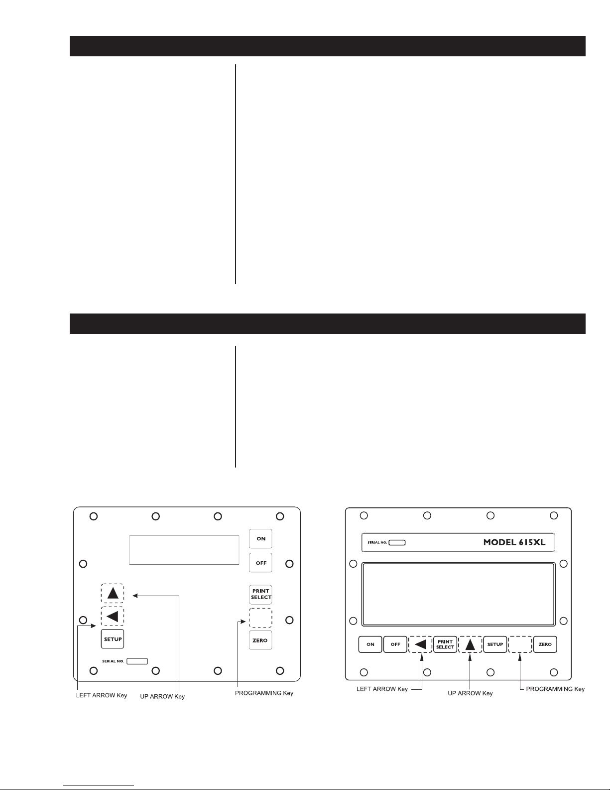
Configuration and calibration programming is entered with three hidden
keys—keys not intended for end-user access. A hidden programming key
accesses the set-up modes, and two hidden arrow keys select and enter
data within the set-up modes. The hidden keys also access the internal raw
counts value and the software release number. Figure 1 below shows the
locations of the hidden keys on the Model 615/XL.
The three hidden keys are touch-sensitive, as are all the keys on the Model
615/XL. However, unlike other keys, the three hidden keys do not have key
faces. These keys are hidden from end users because access to the set-up
modes is intended only for trained technicians who use this service manual.
Hidden Keys on the Front Panel of the Model 615/XL Farm Indicator
Figure 1
Model 615/615XL Indicator Service Manual
5
Page 6

Entering Data with Hidden Arrow Keys
The hidden arrow keys are used only for data entry. You will use this keying
procedure to enter two kinds of numeric data with the hidden arrow keys: a
configuration code and a custom sensitivity rating. The configuration code
and the custom sensitivity rating are each treated separately in sections
If at any time you enter an
incorrect number, press CLEAR
to delete the number, then rekey.
following this one. Refer to this section when you need to enter a number or
numbers. (See Figure 2: Programming Flow Chart.)
Example: To key in the number 5121
1. Press the ⇑ key repeatedly until the 5 appears on the display.
2. Press the ⇐ key once to move the 5 one space to the left.
3. Press the ⇑ key until 1 appears.
4. Press the ⇐ key once to move the 51 one space to the left.
5. Press the ⇑ key until the 2 appears.
6. Press the ⇐ key once to move the 512 one space to the left.
7. Press the ⇑ key until 1 appears.
8. After your desired number has been entered, press PRINT/SELECT to
display ConF. You may now:
a. Continue through the setup cycle by pressing SETUP (See Fig.
2: Programming Flow Chart)
or b. Return to the weigh mode by pressing ZERO.
Viewing the Current Configuration Code
A configuration code is a four- or five-digit number that configures the
indicator for the following operational parameters:
Parameter: Represented by:
Axle Size 1st & 2nd digits
Capacity x Increment Size 3rd digit
Auto Zero Tracking 4th digit
Units of Measure and Capture Mode 5th digit
Refer to Figure 2: Programming Flow Chart.
1. Press the hidden PROGRAMMING key for five seconds to display the
configured transducer trade name: [ 6 1 5 ] Weigh-Tronix Weigh Bar
2. Press SETUP to display [ C o n f ].
3. Press PRINT/SELECT to display the current configuration code.
[ E A t n ] Eaton Weight Transducer
[ J S t r ] J-Star Weight Transducer
4. Press PRINT/SELECT to redisplay [ C o n f ].
5a. Access the next programming display by pressing SETUP.
5b. Return to weighing mode by pressing ZERO.
6
Model 615/615XL Indicator Service Manual
Page 7

7
Model 615/615XL Indicator Service Manual
Figure 2
Programming Flow Chart for the Model 615/XL Farm Indicator
Page 8

Entering a New Configuration Code
Refer to Figure 2: Programming Flow Chart.
1. Determine an appropriate configuration code for your weighing system.
To do so, consult the following two sections:
• Determining Axle Sizes, and
• Determining a Configuration Code.
Refer also to:
• Table 2: Configuration Code Chart, and
• Table 3: Valid Numbers for the Configuration Code.
Study the text and tables listed above and carefully follow all accompanying
instructions to construct a unique four-digit or five-digit configuration code
for your weighing system. Use the following blanks to write out your configuration code for quick reference as you key in the code in step 5 below. Digit
place #1 is to be used only if you construct a five-digit configuration code. A
four-digit configuration code uses digit places #2, #3, #4, and #5, but not #1.
Your configuration code: ____ ____ ____ ____ ____
Digit place #s: #1 #2 #3 #4 #5
2a. Press the hidden PROGRAMMING key for five seconds to view the
transducer trade name display: [ 615] Weigh-Tronix Weigh Bar
[ E A t n ] Eaton Weight Transducer
[ J S t r] J-Star Weight Transducer
2b. Press the hidden PROGRAMMING key for five more seconds to change
the transducer trade name display. Repeat as needed to cycle through
all three trade names.
3. Press SETUP to display [ C o n f ].
4. Press PRINT/SELECT to display the current configuration code.
5. Key in the configuration code for your weighing system according to
previous instructions entitled Entering Data with Hidden Arrow Keys.
6. Press PRINT/SELECT to redisplay [ C o n f ].
7a. Access the next programming display by pressing SETUP.
7b. Return to the weighing mode by pressing ZERO.
8
Model 615/615XL Indicator Service Manual
Page 9

Determining Axle Sizes
To use the configuration code chart in Table 2 for determining an appropriate configuration code for your weighing system, you must first know the
calibration axle size of the Weigh Bar(s) or alternative weight transducer(s).
Physical axle size (the measured diameter of a bar) and calibration axle size
(the measurement marked on a bar) are not the same for some Weigh Bars.
Read about the following combinations of physical axle sizes and calibration
axle sizes, and follow the guideline that applies to your bar(s):
• If your weight transducer measures five-eighths inch (5/8") in diameter,
but is marked with a calibration axle size of 2-1/4" D (Dual), use data
shown in Table 2 for a five-eighths-inch (5/8") bar.
• If your weight transducer measures one inch (1") in diameter, but is
marked with a calibration axle size of 2-1/8", use data shown in Table 2
for a one-inch (1") bar.
• For weight transducers which have a physical axle size of either fiveeighths inch (5/8") or one inch (1"), but which are marked with a
calibration axle size other than 2-1/4" D or 2-1/8" respectively, use data
shown in Table 2 for Custom Sensitivity and Capacity x Increment.
• For all other weight transducers: Whether the physical axle size of the
bar and the calibration axle size marked on the bar do or do not match,
use data shown in Table 2 for the calibration axle size marked on the
bar.
Determining a Configuration Code
Table 1 is an example of a set of configuration choices for a Model 615/XL
weighing system. Table 1 shows you how selections for the Model 615/XL’s
configurable parameters would be represented by a configuration code of
5121, according to the configuration code chart in Table 2. You can see that
each digit in the code represents a parameter, and the value of each digit
represents a selection for that parameter as shown in Table 2.
A Sample Set of Configuration Choices
Its Corresponding Configuration Code (5121)
Parameter Represented Selection Config.
Axle size 2nd digit 2-1/8" 5
Capacity X increment size 3rd digit 20k x 2 1
Auto zero tracking 4th digit ±1.0 division 2
Units of measure and
Capture mode 5th digit Ib/On 1
Configuration code 5121 uses only the
2nd, 3rd, 4th and 5th of five available digits.
Table 1
and
by Code
Model 615/615XL Indicator Service Manual
9
Page 10

The sample configuration code, shown in bold type in Table 1, may be
written horizontally, with digit places numbered, as follows:
Sample configuration code: 51 2 2
Digit place #s: 1 2 3 4 5
Remember, a four-digit configuration code uses digit places #2, #3, #4, and
#5, but not #1. Digit place #1 is to be used only if the configuration code has
five digits. Five digits are required only for bars with calibration axle sizes of
3-1/8 inches and 4 inches and when custom sensitivity (with capacity x
increment) is appropriate (See Table 2).
10
Model 615/615XL Indicator Service Manual
Page 11
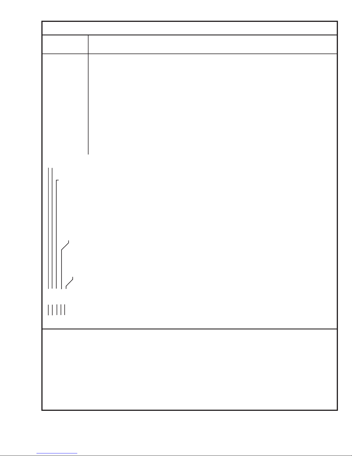
Table 2 Configuration Code Chart for Weigh-Tronix Weigh Bars
CALIBRATION
AXLE SIZE+ CAPACITY x INCREMENT SIZE
0: 5/8"* 200 x 0.01 200 x 0.02 200 x 0.05 2K x 0.1 2K x 0.2 2K x 0.5
1: 1"* 2K x 0.1 2K x 0.2 2K x 0.5 20K x 1 20K x 2 20K x 5
2: 1-1/4" 2K x 0.1 2K x 0.2 2K x 0.5 20K x 1 20K x 2 20K x 5
3: 1-7/8" 20K x 1 20K x 2 20K x 5 200K x 10 200K x 20 200K x 50
4: 2" 20K x 1 20K x 2 20K x 5 200K x 10 200K x 20 200K x 50
5: 2-1/8 20K x 1 20K x 2 20K x 5 200K x 10 200K x 20 200K x 50
6: 2-1/4" 20K x 1 20K x 2 20K x 5 200K x 10 200K x 20 200K x 50
7: 2-1/4"D 20K x 1 20K x 2 20K x 5 200K x 10 200K x 20 200K x 50
8: 2-1/4"D-P 200K x 10 200K x 20 200K x 50 200K x 100 200K x 200 200K x 500
9: 2-1/2 20K x 1 20K x 2 20K x 5 200K x 10 200K x 20 200K x 50
10: 3-1/8" 200K x 10 200K x 20 200K x 50 200K x 100 200K x 200 200K x 500
11: 4" 200K x 10 200K x 20 200K x 50 200K x 100 200K x 200 200K x 500
12: CC-20 20K x 1 20K x 2 20K x 5 200K x 10 200K x 20 200K x 50
13: Alley Weigh 2K x 0.1 2K x 0.2 2K x 0.5 20K x 1 20K x 2 20K x 5
19: Custom Sensitivity and Capacity x Increment (See text: Configuring Custom Sensitivity with Capacity x Increment Size.)
➤
➤
➤
Column
Numbers 0 1 2 3 4 5
➤
AZT (Divisions)
0: OFF
1: ±.5
2: ±1.0
3: ±3.0
4: ±10.0
➤
UNITS CAPTURE
0: lb Off
1: lb On
2: kg Off
3: kg On
➤
➤
➤
➤
➤
{
{
{
{
{
{
_ 5 1 2 1 is the Configuration Code number representing selections cited in USING TABLE 1: CONFIGURATION CODE EXAMPLE.
➤
➤
➤
➤
➤
➤
➤
➤
➤
➤
1 2 3 4 5 are place numbers for each digit in Configuration Code.
+ Axle size determines Weigh Bar sensitivity in mV/V. Refer to Table 4 to relate axle sizes to exact sensitivity
values.
K = Multiply by 1000
* If physical axle size of your Weigh Bar equals 5/8" or 1", but differs from its identifying calibration axle size,
see text: AXLE SIZES.
D-P =Dual Platform: Eight 350-ohm Weigh Bars and junction box with span pots.
D =Dual: double-ended Weigh Bar
Model 615/615XL Indicator Service Manual
11
Page 12
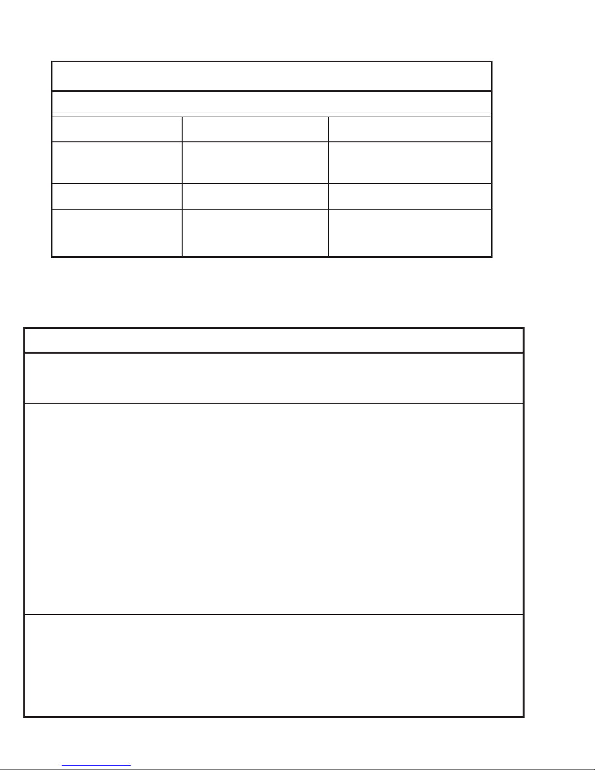
Table 3: Valid Numbers for the Configuration Code
PARAMETERS VALID #'S INVALID #'S
Axle Size 0 - 13, 19 14 - 18
Capacity x Increment Size 0 - 5 Any number greater than 5 will be
recognized as a 5.
Warning Alarm Factor 0 - 9
Units and Auto Hold 0 - 3 Any number greater than 3 will be
recognized as a 3.
Table 4: Model 615/XL Calibration Table
Calibration
Axle Scale Number of
Size Capacity Weigh Bars mV/V Calibration
5/8"* 200 lb 4 0.2 180.039 lb
1"* 2,000 lb 4 0.5 1,831.03 lb
1-1/4" 2,000 lb 4 0.2 1,742.58 lb
Alley Weigh 2,000 lb 2 1.0 1,913.8 lb
1-7/8" 20,000 lb 4 0.7 17,965.8 lb
2" 20,000 lb 4 0.6 19,143.8 lb
2-1/8" 20,000 lb 4 0.5 18,310.3 lb
2-1/4" 20,000 lb 4 0.4 18,003.9 lb
2-1/4"D 20,000 lb 4 0.2 18,003.9 lb
2-1/2" 20,000 lb 4 0.3 18,811.4 lb
2-1/4"D 200,000 lb 4 1.0 90,019.3 lb
2-1/4"D-P 200,000 lb 8/350 1.0 186,816.0 lb
3-1/8" 200,000 lb 4 1.0 126,402.0 lb
* If physical axle size of your Weigh Bar equals 5/8" or 1", but differs from its identifying calibration axle size,
see previous text: AXLE SIZES.
D-P is Dual Platform: Eight 350-ohm Weigh Bars and junction box with span pots.
D is Dual: double-ended Weigh Bar.
12
Model 615/615XL Indicator Service Manual
Page 13

Determining the Custom Sensitivity Rating
This procedure allows you to configure a sensitivity rating for a weight
transducer that is not referenced in Table 2. You may configure another
manufacturer’s weight transducer for interface with the Model 615/XL.
Before starting the keying procedure for configuring custom sensitivity, you
must verify three facts about the transducer(s) being used:
• Trade name of the transducer
• Sensitivity rating of the transducer
• Capacity x increment size of the transducer
Trade Name of the Transducer
To configure custom sensitivity for Weigh-Tronix Weigh Bars, see the next
subsection, Sensitivity Rating of the Transducer.
To configure for transducers from manufacturers other than Weigh-Tronix,
refer now to instructions located in the Programming Appendix. If you find
that custom configuration of sensitivity is required for your transducer(s),
return to this section and proceed to the next topic.
Sensitivity Ratings of the Transducer
1. Determine the sensitivity rating, that is, the mV/V output at full capacity,
for the weight transducer(s) you are using. You will probably find this
information stamped or printed on the transducer.
2. Call the factory at 1-800-458-7062 for help in determining the Model 615/
XL sensitivity rating for your transducer(s). Because a number of
different types of bars are used by various manufacturers of weight
transducers, it is impossible to provide generic instructions on determining Model 615/XL sensitivity ratings for all the weight transducers
available.
3. Write down your calculated sensitivity rating here using the following format:
n. nnnnnnn = your sensitivity rating
1 2345678 = digit places
You may key in a mV/V value of up to eight digits. Selection range for
sensitivity is from 0.075 to 6.0 mV/V. Keep your notation handy for entry
in steps 5, 6, 7, and 8 of the following keying procedure.
Capacity x Increment Size of the Transducer
4. Refer to Table 5 and locate a capacity x increment size combination that
is appropriate for your Model 615/XL.
5. Look on the right end of Table 5, and identify the number of the row in
which your selected capacity x increment size is located. Then write
down that row number here: __________________
You will need this row number in step 11 of Keying In the Custom
Sensitivity Rating.
Model 615/615XL Indicator Service Manual
13
Page 14

Table 5: Row Numbers for Custom Capacity x Increment Size
Column Numbers: Row
012345#’s
200K x 10.0 200K x 20.0 200K x 50.0 200K x 100.0 200K x 200.0 200K x 500.0 0
20K x 1.0 20K x 2.0 20K x 5.0 200K x 10.0 200K x 20.0 200K x 50.0 1
2K x .1 2K x .2 2K x .5 20K x 1.0 20K x 2.0 20K x 5.0 2
200 x .01 200 x .02 200 x .05 2K x .1 2K x .2 2K x .5 3
Keying In the Custom
Sensitivity Rating
Refer to Figure 2: Programming Flow Chart.
1. Press the hidden programming
key for five seconds... [ 6 15 ] is displayed.
2. Press SETUP twice... [ C u S t ] is displayed.
3. Press PRINT/SELECT... [ U P P r ], which stands for “upper,”
is displayed.
U P P r announces the next display and is an arbitrary label for the first
four digits of the eight-digit custom sensitivity rating (from step 3 of the
previous section, Determining the Custom Sensitivity Rating).
4. Press PRINT/SELECT again... the first four digits of the currently
configured eight-digit custom
sensitivity rating are displayed.
5. Use the UP ARROW and
LEFT ARROW keys (see
Entering Data with Hidden Arrow
Keys) to enter the first four digits
of the custom configuration
rating appropriate for your
Model 615/XL (from step 3 of
Determining the Custom
Sensitivity Rating).
6. Press PRINT/SELECT after
7. Press SETUP... [ L o ], which stands for “lower,” is
8. Press PRINT/SELECT to display
9. Then use the UP ARROW and
14
Model 615/615XL Indicator Service Manual
entering your first four digits... [ U p p r ] is redisplayed.
displayed.
L o announces the next display and is an arbitrary label for the final four
digits of your custom sensitivity rating.
the final four digits of the
currently configured eight-digit
custom sensitivity rating.
LEFT ARROW keys (See
Entering Data with Hidden Arrow
Keys) to key in the final four
digits of your custom
configuration rating.
Page 15

10. Press PRINT/SELECT after
entering your final four digits... [ L o ] is redisplayed.
11. Press SETUP... [ C A P ], which indicates the capac-
ity value, will be displayed.
12. With [ C A P ] displayed, press
PRINT/SELECT to display the
currently configured capacity.
13. Then use UP ARROW and
LEFT ARROW keys to enter the
row number that you noted in
step 5 of Determining the
Custom Sensitivity Rating.
14. Press PRINT/SELECT... [C A P ] is redisplayed.
15. Press SETUP... [ C u S t ] is displayed.
16. You now have two choices:
(See Figure 2: Programming
Flow Chart):
16a. Continue through the setup
cycle to the SPAn (span)
display by pressing SETUP,
and refer to the appropriate
calibration instructions in
this manual, OR
16b. Return to the weigh mode
by pressing ZERO.
Calibrating with a Known Weight
Use a reliable known calibration weight equal to or greater than the maximum weight of material that will be weighed.
1. Empty and zero the scale.
2. Press the hidden
PROGRAMMING key for five
seconds to display [ 6 1 5 ].
3. Press SETUP, repeating two
or three times. . . Display shows [ S P A n ].
4. Press PRINT/SELECT... Zero weight value should be dis-
5. Place a known calibration weight
on the scale.
played before you continue. If rezeroing is necessary, press ZERO.
Model 615/615XL Indicator Service Manual
15
Page 16

6. Adjust the span, using the
UP ARROW key and the
LEFT ARROW key until the value
of the known calibration weight is
displayed...
• To increase the displayed span value, press UP ARROW.
• To decrease the displayed span value, press LEFT ARROW.
• To return to the factory calibration value, press the hidden PROGRAM-
MING key.
7. Press PRINT/SELECT to redisplay
[ S P A n ] indicating that
calibration is complete.
8. You now have two choices below: (See Figure 2: Programming Flow
Chart).
A. Continue in the setup cycle to the internal raw counts display by
pressing SETUP ([ I n t r ] appears), and proceed to the section
Viewing the Internal Raw Counts Display, OR
B. Return to the weighing mode by pressing ZERO.
Getting Ready to
Calibrate with a BLH
Model 625 Calibrator
Table 6: Calibrator Connections and Calibration Tables
Number of Weigh Bars and Instructions for Connecting Indicator Calibration Tables
Type of Connector with E3LH Calibrator
Calibrating with a BLH Model 625 Calibrator is a procedure intended only for
trained technicians using specialized equipment in a controlled environment.
1. Refer to Table 6 and follow the appropriate instruction shown in Table 6
to connect the BLH Model 625 Calibrator to the Model 615/XL Indicator.
2. Using the appropriate calibration table as referenced in Table 6, find the
highest mV/V reading on that calibration table for the Weigh Bars on
your scale system. The mV/V readings are categorized on the calibration table according to Weigh Bar size and scale capacity.
3. In this blank, , write down your highest mV/
V reading. You will use this mV/V reading in step 6 of the next set of
instructions, Calibrating with a BLH Model 625 Calibrator.
Four Weigh Bars w/ 5-Pin Connectors Connect single cable from BLH Calibrator Use W-T Spec P/N 24375 Model 700
Four Weigh Bars w/ 4-Pin Connectors Connect four cables from modified BLH Use W-T Spec P/N 14599 Farm Scale
One Weigh Bar w/ 7-pin Connector Connect single cable from BLH Calibrator Use W-T Spec P/N 24375 Model 700
16
to one of the 5-pin Weigh Bar connectors. Calibration Tables
Calibrator to all four 4-pin Weigh Bar connectors Calibration Tables.
to the single 7-pin Weigh Bar Connector Calibration Tables
Model 615/615XL Indicator Service Manual
Page 17

Calibrating with a BLH
Model 625 Calibrator
1. Dial the BLH calibrator to zero
mV/V.
2. Press the ZERO key to zero the
indicator.
3. Press the hidden
PROGRAMMING key for 5
seconds [ 6 15 ] is displayed.
4. Press SETUP, repeating as
necessary (either two or three
times) [ S P A n ] is displayed.
5. Press PRlNT/SELECT... Zero weight value should be dis-
played.
If zeroweight is not displayed,
press ZERO.
6. Turn the dial to the highest mV/V
setting for this system, as
determined in step 2 and noted
in step 3 of Getting Ready to
Calibrate with a BLH Model 625
Calibrator... The value displayed by the indicator
is the scale’s gross weight reading
for the known weight prior to calibra-
tion and may be inaccurate.
7. Adjust the span, using the
UP ARROW key and the
LEFT ARROW key until the
value of the known calibration
weight is displayed.
· To increase the displayed span value, press UP ARROW.
· To decrease the displayed span value, press LEFT ARROW.
· To return to the factory calibration value, press the hidden
PROGRAMMING key.
8. Press PRINT/SELECT... [ S P A n ] is redisplayed, indicating
that calibration is complete.
(See Figure 2: Programming Flow
Chart):
A. Continue in the setup cycle
to the internal raw counts
displayby pressing SETUP... [ I n t r ] is displayed.
and referring to the
instructions, Viewing the
Internal Raw Counts Display.
OR
B. Return to the weighing mode
by pressing ZERO.
Model 615/615XL Indicator Service Manual
17
Page 18

Viewing the Internal Raw Counts Display
1. Press the hidden
PROGRAMMING key for five
seconds... [ 6 1 5] is displayed.
2. Press SETUP until... [I n t r] is displayed.
3. Press PRINT/SELECT... The internal raw count value is
You May Adjust Absolute
Zero if your scale system
includes a junction box
4. Press PRINT/SELECT again... [I n t r] is displayed.
5. You now have two choices: 5a or 5b (See Figure 2: Programming Flow
Chart):
a. Continue in the setup cycle to view and adjust the over range by
pressing SETUP [O V E r], and referring to instructions, Viewing the
Software Version Number, OR
b. Return to the weighing mode by pressing ZERO.
displayed. At 1.0 mV/V, the display
will always read 10,955 counts.
Viewing and Selecting Overcapacity
1. Press the hidden
PROGRAMMING key for five
seconds... [ 6 1 5] is displayed.
2. Press SETUP until... [O V E r] is displayed.
3. Press PRINT/SELECT... [ - - - - ] is displayed, representing
4a. With the correct capacity
displayed, press PRINT/SELECT
and proceed to Step 5... [O V E r] is displayed.
4b. If the incorrect capacity is
displayed, key in a new value
using the hidden arrow keys (see
Entering Data with Hidden Arrow
keys on page 2)... New amount is displayed.
5. You now have two choices: 5a or 5b (See Figure 2: Programming Flow
Chart):
20,000 capacity.
18
Model 615/615XL Indicator Service Manual
a. Continue in the setup cycle to the continuous serial output selection
by pressing SETUP [b r d], and referring to instructions, Selecting
Continuous Serial Output, OR
b. Return to the weighing mode by pressing ZERO.
Page 19

Selecting Continuous Serial Output
1. Press the hidden PROGRAMMING
key for five seconds... [ 6 1 5] is displayed.
2. Press SETUP until... [b r d] is displayed.
3. Press PRINT/SELECT... [O F F] or [o n] is displayed.
4. Press SETUP to toggle between
the two options.
4. Press PRINT/SELECT with the
chosen option displayed... [b r d] is displayed.
5. You now have two choices:
5a or 5b (See Figure 2:
Programming Flow Chart):
a. Continue in the setup cycle to
the software version display by
pressing SETUP [S o F t], and
referring to instructions,
Viewing the Software Version
Number, OR
b. Return to the weighing mode
by pressing ZERO.
Viewing the Software Release Number
1. Press the hidden PROGRAMMING
key for five seconds... [6 1 5] is displayed.
2. Press SETUP several times to
display... [S o F t].
3. Press PRINT/SELECT... the software release number for the
4. You now have two choices: 4a or 4b (See Figure 2: Programming Flow
Chart):
a. Continue in the setup cycle to
the transducer trade name
display by pressing SETUP,
OR
version of software installed in your
indicator is displayed.
b. Return to the weighing mode
by pressing ZERO.
Model 615/615XL Indicator Service Manual
19
Page 20

Circuit Descriptions
Main Printed Circuit Card
This printed circuit card contains the
• Power Supply
• Analog-To-Digital Circuitry
• Microprocessor Circuitry
• Display Circuitry.
Power Supply
To prevent the unit from turning
off below 10 volts, remove CR5
and C36. When configured this
way, the unit will return to the
Gross mode if it loses power.
This indicator, which is energized by 10 to 18 vdc in reference to a NEGATIVE GROUND utilizes one five amp fuse mounted on the bottom of the
chassis for current protection. (Systems with a positive ground are modified
by cutting jumpers from E11 to E12 and E9 to E10. Then install jumpers
from E9 to E12 and E10 to E11.)
The circuit card receives power from the fuse at P2 and is protected against
high voltage transients with varistor RV1.
Input voltage is monitored by 16 volt zener diode VR2. If the voltage across
VR2 exceeds 16 vdc, Q3 will turn “ON” holding the power circuitry in the
“OFF” condition. In addition, if the input voltage drops below 10 volts DC,
PA7 disables the power circuitry by outputting a low signal.
A “Power On” command is generated when the ON key is pressed. This
turns Q5 on and provides a low signal to +8v regulator (u18) pin1 enable
input. When the power is turned off, the Q5 turns off, the Q4 turns on and a
high signal disables (U18) the +8 regulator and turns it off.
20
Model 615/615XL Indicator Service Manual
Page 21

The -7.5 vdc supply voltage is established by U7, a voltage convertor. This
device inverts the input voltage to a -7.5 vdc level.
The +5 vdc voltage is provided by U8, a 7805 regulator.
As soon as the +8 volt power supply voltage is present, Q2 turns on which
turns on the DS2 and DS3 LEDS
Analog to Digital
Circuitry
The analog-to-digital circuitry consists of two weight voltage amplifiers (U1
and U2), a reference amplifier (U3), an analog switch (U4), switch control
logic gate (U14C), a dual slope integrator (U5), and a comparator (U6).
An 8 vdc excitation voltage is supplied to the weight sensors from P1 pins 1
and 6. The millivolt signal received back from the weight sensors enters the
analog-to-digital circuitry at P1, pins 3 and 4.
This millivolt signal is amplified and filtered by U1 and U2 to establish the
amplified weight voltage (0 to +9 vdc) at U2 pin 6. This weight voltage is
then provided to U4 pin 5. A logic low during the weight voltage interval at
U4 pin 1 enables the amplified weight voltage to be received by the dual
slope integrator (U5). Starting at zero volts, the integrator capacitor (C20)
charges at ramp angle directly proportional to the amplified weight voltage
but of opposite polarity. As the amplified weight voltage increases, the
integrator output ramps more in the negative direction.
The voltage received from the sense lines enters the analog-to-digital
circuitry at P1 pins 2 and 5. This sense voltage establishes a reference
voltage of -9 vdc at U3 pin 6. The reference voltage is applied to U4 pin 10.
After the integrator capacitor has been charged for a fixed period of time,
the Weight Voltage Interval, U4 pin 1 goes high. U14 applies a logic low to
pin 14 of U4 which allows the reference voltage to be applied to the integrator. Since the reference voltage (-9 vdc) is of opposite polarity to the amplified weight voltage, it causes the integrator output to ramp back toward zero.
(This period of time is known as the Reference Voltage Interval.)
While the integrator output is ramping back to zero, the comparator (U6)
signals the microprocessor to record this period of time in clock pulses. The
microprocessor uses this number of pulses to calculate the amount of
weight on the scale.
When the integrator reaches zero, the comparator output goes low which
triggers U14C to remove the logic low at U4 pin 14 completing one analogto-digital cycle.
This analog-to-digital conversion repeats at a frequency of 30 hertz.
Model 615/615XL Indicator Service Manual
21
Page 22

Microprocessor
Circuitry
The Microprocessor Circuitry consists of a Motorola MC68HC11A1 8-bit
microprocessor IC (u11), a 74HC573 tristate latch (U12), a 27C128 EPROM
(U13), and various other components.
The microprocessor features on chip memory 256 bytes of RAM, 512 bytes
of EEPROM, along with a Computer Operating Properly (COP) watch dog
system.
A 2 MHZ internal clock is contained in the microprocessor and is controlled
by an external crystal (Y1). Output (ECLK) from this clock provides timing
reference for the EPROM (U13), and input to voltage monitoring circuit U9.
The microprocessor communicates with Analog-to-Digital switch control
logic gate U14 through ports PA2 and PA6. Through U14, the timing reference for the Reference Voltage Interval and Weight Voltage Interval are
provided.
The switches on the front panel receive a signal from ports PD2-PD5 on the
microprocessor and they are monitored for an electrical change by ports
PE0PE3 on the microprocessor.
As signals are received by the microprocessor, it will send them to the
EPROM (U13) on the address lines A0-A15. The signals will be translated
and held by U12. Once all translating is completed, the microprocessor will
enable U12 to return the new information on data lines D0-D7 to the microprocessor. Then, the appropriate device will receive a signal from the
microprocessor.
The Computer Operating Properly (COP) watch dog system in the microprocessor detects errors introduced by electromagnetic interference. If an error
is detected, the microprocessor is reset and operation continues. When the
indicator is powered up, the momentary displayed "hi" message, indicates
the watch dog system is active.
If a "hi" message is displayed, the indicator will perform correctly, but will not
be guarded by the COP watch dog system. This may happen when a new
microprocessor IC is installed. The COP watch dog system can be activated
by following this procedure:
• Turn the indicator OFF jumper P7-1 to P7-2 and P6-1 to P6-2
• Turn the Model 615/XL ON for a few seconds
• Turn the Model 615/XL OFF
• Remove the jumpers
22
Model 615/615XL Indicator Service Manual
Page 23

Display Circuitry
The six digit liquid crystal display (DS1) features black segments against a
silver transflective background.
Liquid crystal display driver U15 requires a +5 vdc power supply and two
signal inputs from the microprocessor to function: (1) a 33-bit serial data
input and (2) a microprocessor controlled input. When both of these conditions have been met, the display driver will energize the appropriate segments on the display.
Optional RS-232 or Remote
Circuitry
To Install Remote Receiver
Additional circuitry required to provide either an RS-232 communications
interface or a remote display interface requires R49-57, C48-51, U16, U10,
and P6 connector.
The RS-232 transmitter/receiver (U10) internally generates +10v and -10 v
supplies and meets all EIA RS-232C specifications. Through U10, the
microprocessor communicates with peripherals which will accept the following protocol: baud rate 1200, 1start bit, 8 data bits, no parity, and one stop
bit. The RS-232 communications port supports X-on (HEX 11), X-off (HEX
13_) handshake and responds to an inquire character (HEX 05) print
request.
The invertor/buffer gates (U16) are used in the remote clock, remote data,
remote zero, and remote print lines to provide isolation and assure proper
logic; levels to and from the remote display.
P6 connector provides external access to power supply voltages, RS-232
data lines, remote display drive lines, remote zero lines, and remote print
lines.
After installing PC board assembly P/N 27643-0030 as shown in assembly
section, plug 3 pin cable assembly into P8. This enables user to have
remote zero capabilities within the Model 615/XL. Be sure to match dip
switch selections between receiver card and transmitter.
Model 615/615XL Indicator Service Manual
23
Page 24

24
Model 615/615XL Indicator Service Manual
Page 25

MODEL 615 / 615XL INDICATOR 12VDC
SYSTEM BLOCK DIAGRAM
25
Page 26

MODEL 615 INDICATOR 12VDC
PARTS AND ASSEMBLY
26
ITEM
NO. DESCRIPTION W-T P/N QTY
1 MOUNTING BRACKET 11899-0043 1
2 RUBBER MOUNT 17807-0058 4
3 NEOPRENE WASHER 27357-0010 4
4 ENCLOSURE 47017-0010 1
5 MAIN PC BOARD 47301-0049 1
6 MAIN PC BOARD W/ RS-232, R/D 47301-0056 1
7 “REMOTE ZERO” RECEIVER KIT (OPTIONAL) 27643-0030 1
8 BEZEL 21356-0014 1
9 SCREW, #10-32 x .75"L 18087-0073 12
10 KEYPAD ASS'Y 47697-0017 1
11 SCREW, #10-32 x .31"L 14473-0348 8
12 XM710, HAND HELD REMOTE (OPTIONAL) 27809-0014 1
13 PNL ASSY, SINGLE W/B CONN (7-PIN) 52955-0055 1
PNL ASSY, SINGLE W/B CONN (7-PIN) W/RD or RS232 52955-0105 1
PNL ASSY 3-W/B CONN (4-PIN) 52955-0048 1
PNL ASSY 3-W/B CONN (4-PIN) W/RD or RS232 52955-0097 1
PNL ASSY 3-W/B CONN (5-PIN) 52955-0030 1
PNL ASSY 3-W/B CONN (5-PIN) W/RD or RS232 52955-0089 1
PNL ASSY 4-W/B CONN (4-PIN) 52955-0022 1
PNL ASSY 4-W/B CONN (5-PIN) 52955-0014 1
PNL ASSY 4-W/B CONN (4-PIN) W/RD or RS232 52955-0071 1
PNL ASSY 4-W/B CONN (5-PIN) W/RD or RS232 52955-0063 1
14 FUSE HOLDER 15455-0016 2
15 FUSE (5 AMP) 15453-0042 2
Page 27

MODEL 615 INDICATOR 12VDC
KEYPAD OVERLAY (P/N 47697-0017)
AND SCHEMATIC
27
Page 28

MODEL 615 INDICATOR 12VDC
MAIN PC BOARD A/D (P/N 47301-0049 –0056) AND
COMPONENT PARTS LIST
28
SYMBOL DESCRIPTION W-T P/N
B1 BATTERY, 3.6 V 23957-00 21
C1,2,5,6,9,
11,12,14,1
5,22,23,29
,30,32,33
CAP. 0.1 UF 100 V 15623-0120
C3,4 CAP. .22 UF 50 V 23267-0117
C7,8,18,19
,27,28
CAP. 1.0 UF 35 V 22327-2519
C10,38-46,
49,55-58
CAP. 47 UF 16 V 17993-0094
C13,17,21,37CAP. 100PF 200 V 15619-0134
C16 CAP. 1.0 UF 50 V 23267-0158
C20 CAP. .15 UF 100 V 18083-0127
C24 CAP. 4700PF 100 V 15620-0018
C25,36,59,
60,61
CAP. 0.01 UF 100 V 15620-0123
C26,47,48,
50,53
CAP. 0.1 UF 50 V 46684-0048
C31 CAP. 470 UF 35 V 17995-0134
C34 CAP. 1000 UF 35 V 17995-0142
C35 CAP. 10 UF 35 V 22327-2618
C51,52 CAP. 22PF 200 V 15619-0050
C54 CAP. 1000 PF 200 V 15619-0258
CR1,4 DIODE, 1N4142 15668-0076
CR,6,7 DIODE, 1N4004 15668-0043
CR5 DIODE, 1N4148 15668-0035
DS1 DISPLAY, LCD 22329-0040
DS2,3 LED, H-2000 27472-00 10
FL1-6 FILTER, EMI 46547-0011
L1,2 CHOKE, 10 UHY 15779-0015
P1,2 CONN. 6 PIN 17794-0053
P4 CONN. 12 PIN 17731-0117
P5 (used with
-0056 only)
CONN. 14 PIN 17794-0137
P6,7 CONN. 2 PIN 17734-0015
P8 (used with
-0049 only)
CONN. 3 PIN 17794-0020
Q2 TRANSISTOR, TIP122 16271-0032
Q3-5 TRANSISTOR, 2N3904 15665-0012
R57,12,17,
19,43
RESISTOR, 100 OHM 14477-0492
R8 RESISTOR, 9.09 K 17873-1899
R9 RESISTOR, 64.9 K 17873-2715
R10 RESISTOR, 196 K 17873-31 76
R11 RESISTOR, 8.06 K 15677-3764
R13,14 RESISTOR, 37.4 K 17873-2483
R15,16 RESISTOR, 42.2 K 17873-2533
R18 RESISTOR, 110 K 15673-48 57
R20,21 RESISTOR, 182 OHM 15677-2188
R22 RESISTOR, 470 K 14477-13 75
SYMBOL DESCRIPTION W-T P/N
R23 RESISTOR, 510 K 14477-1383
R26,30 RESISTOR, 2.0 K 14477-0807
R27 RESISTOR, 330 OHM 15670-0619
R28 RESISTOR, 750 OHM 15670-0700
R29 RESISTOR, 910 OHM 14477-0724
R31-34 RESISTOR, 15 K 14477-1011
R35 RESISTOR, 0.475 OHM 46602-0179
R41,42 RESISTOR, 10.0 K 15677-3855
R44 RESISTOR, 3.9 K 14477-0872
R45,51 RESISTOR, 4.7 OHM 14477-0179
R46,47 RESISTOR, 22 OHM 14477-0336
R48 RESISTOR, 78.7 K 15677-4713
R49 RESISTOR, 13.0 K 15677-3962
R52 RESISTOR, 10 MEG 14477-1698
R53 RESISTOR, 5.1 K 14477-0906
R54-57 RESISTOR, 120 OHM 14477-0518
R58-52 RESISTOR, 22K 14477-1052
R63,64 RESISTOR, 39 K 14477-1110
R65 RESISTOR, 22 MEG 14477-1771
R66 RESISTOR, 5.23K 15673-3586
R67 1.0K 15673-2893
RN1 RESISTOR NETWORK, 5.62/301 K 23256-0011
RN2-4 RESISTOR NETW ORK, 9 X 10 K 17852-0045
RN5,6 RESISTOR NETWORK, 4 X .1 K 17852-0037
RV1 VARISTOR, V827A12 16046-0028
U1 IC, 7652 14323-0464
U2,3,5,7 IC, 308A 14323-0266
U4 IC, DG200 14323-0241
U6 IC, 311 14323-0258
U8 VO LTAGE REGULATOR 7660 15658-0227
U9 IC, 690 15657-0673
U10 VOLTAGE REGULATOR 7805 15658-0011
U11 IC, MC68HC11A1P 15657-0632
U12 IC, 74HC573 18080-055 9
U13 IC, PROGRAMMED MOD 615 29443-0020
U14 IC, 74HC00 18080-0013
U15 IC, 5453N 15657-0624
U16 (used
with -0056
only)
IC, 74HC14 18080-0096
U17 (used
with -0056
only)
IC, MAX232CPE 14323-0621
U18 REGULATOR, TL751MO8KC 15658-0300
U19 REGULATOR, 29412 15658-0359
VR2 DIODE, ZENER 1N5353B 16V 15669-0158
XDS1 SOCKET, SIP 25 PIN 17847-1017
XDS1 SOCKET, SIP 10 PIN 17847-1066
XDS1 BACKLIGHT, DISPLAY 27459-0041
XU13 SOCKET, IC 28 PIN 14361-0079
XU18 HEAT SINK 15556-0014
Y1 CRYSTAL, 8.00 MHZ 16125-0212
Page 29

MODEL 615 INDICATOR 12VDC
MAIN PC BOARD A/D SCHEMATIC
29
Page 30

MODEL 615XL INDICATOR 12VDC
PARTS AND ASSEMBLY
30
ITEM
NO.
DESCRIPTION W-T P/N QTY
1 MOUNTING BRACKET 11899-0043 1
2 RUBBER MOUNT 17807-0058 4
3 NEOPRENE WASHER 27357-0010 4
4 ENCLOSURE 47017-0010 1
5 DISPLAY PC BOARD 48466-0014 1
6 MAIN PC BOARD W/ RS-232, R/D 47301-0064 1
7 “REMOTE ZERO” RECEIVER (OPTIONAL) 51763-0018 1
8 BEZEL 21356-0014 1
9 SCREW, #10-32 x .75"L 18087-0073 12
10 KEYPAD ASS'Y 48715-0013 1
11 SCREW, #10-32 x .31"L 14473-0348 8
12 XM710, HAND HELD REMOTE (OPTIONAL) 51760-0011 1
ITEM
NO.
DESCRIPTION W-T P/N QTY
13 PNL ASSY, SINGLE W/B CONN (7-PIN) 52955-0055 1
PNL ASSY, SINGLE W/B CONN (7-PIN) W/RD or RS232 52955-0105 1
PNL ASSY 3-W/B CONN (4-PIN) 52955-0048 1
PNL ASSY 3-W/B CONN (4-PIN) W/RD or RS232 52955-0097 1
PNL ASSY 3-W/B CONN (5-PIN) 52955-0030 1
PNL ASSY 3-W/B CONN (5-PIN) W/RD or RS232 52955-0089 1
PNL ASSY 4-W/B CONN (4-PIN) 52955-0022 1
PNL ASSY 4-W/B CONN (5-PIN) 52955-0014 1
PNL ASSY 4-W/B CONN (4-PIN) W/RD or RS232 52955-0071 1
PNL ASSY 4-W/B CONN (5-PIN) W/RD or RS232 52955-0063 1
14 FUSE HOLDER 15455-0016 2
15 FUSE (5 AMP) 15453-0042 2
Page 31

MODEL 615XL INDICATOR 12VDC
KEYPAD BOARD ASSEMBLY (P/N 48715-0013)
AND SCHEMATIC
31
Page 32

MODEL 615XL INDICATOR 12VDC
MAIN PC BOARD A/D (P/N 47301-0064) AND
COMPONENT PARTS LIST
32
SYMBOL DESCRIPTION W-T P/N
B1 BATTERY, 3.6 V 23957-0021
C1,2,5,6,9,11,12,
14,15,22,23,26,3
0,32,33 CAP. 0.1 UF 100 V 15623-0120
C3,4 CAP. .22 UF 50 V 23267-0117
C7,8,18,19,27,
28 CAP. 1.0 UF 35 V 22327-2519
C10,38-46,49,
55-58 CAP. 47 UF 16 V 17993-0094
C13,17,21, 37 CAP. 100 PF 200 V 15619-0134
C16 CAP. 1.0 UF 50 V 23267-0158
C20 CAP. .15 UF 100 V 18083-0127
C24 CAP. 4700 PF 100 V 15620-0081
C25,36,59,60 CAP. 0.01 UF 100 V 15620-0123
C26,47,48,50,53 CAP. 0.1 UF 50 V 46684-0048
C31 CAP. 470 UF 35 V 17995-0134
C34 CAP. 1000 UF 35 V 17995-0142
C35 CAP. 10 UF 35 V 22327-2618
C51,52 CAP. 22PF 200 V 15619-0050
CR1,4 DIODE, 1N4142 15668-0076
CR6,7 DIODE, 1N4004 15668-0043
CR5 DIODE, 1N4148 15668-0035
FL1-6 FILTER, EMI 46547-0011
J5 CONN 14 PIN 27487-0054
L1,2 CHOKE, 10 UHY 15779-0015
P1,2 CONN. 6 PIN 17794-00 53
P4 CONN. 12 PIN 17731-0117
P5 CONN. 14 PIN 17794-0137
P6,7 CONN. 2 PIN 17734-00 15
P8 CONN. 3 PIN 17794-0020
Q3-5 TRANSISTOR, 2N3904 15665-0012
R5-7,12,17,19,43 RESISTOR, 100 OHM 14477-0492
R8 RESISTOR, 9.09 K 17873-1899
R9 RESISTOR, 64.9 K 17873-2715
R10 RESISTOR, 196 K 17873-3176
R11 RESISTOR, 8.06 K 15677-3764
R13,14 RESISTOR, 37.4 K 17873-2483
R15,16 RESISTOR, 42.2 K 17873-2533
R18 RESISTOR, 110 K 15673-4857
R20,21 RESISTOR, 182 OHM 15677-2188
R22 RESISTOR, 470 K 14477-1375
R24 RESISTOR, 3.3 K 14477-0856
SYMBOL DESCRIPTION W-T P/N
R26,30 RESISTOR, 2.0 K 14477-0 807
R28 RESISTOR, 750 OHM 15670-0700
R29 RESISTOR, 910 OHM 14477-0724
R31-34 RESISTOR, 15 K 14477-1011
R35 RESISTOR, 0.475 OHM 46602-0179
R41,42 RESISTOR, 10.0 K 15677-3855
R44 RESISTOR, 3.9 K 14477-0872
R45,51 RESISTOR, 4.7 OHM 14477-0179
R46,47 RESISTOR, 22 OHM 14477-0336
R48 RESISTOR, 78.7 K 15677-4713
R49 RESISTOR, 13.0 K 15677-3962
R52 RESISTOR, 10 MEG 14477-1698
R53 RESISTOR, 5.1 K 14477-0906
R54-57 RESISTOR, 120 OHM 14477-0518
R58-62 RESISTOR, 22K 14477-1052
R63,64 RESISTOR, 39 K 14477-1110
R65 RESISTOR, 22 MEG 14477-1771
R66 RESISTOR, 5.23K 15673-3586
R67 RESISTOR, 1.0 K 15673-2893
RN1 RES NET, 5.62/301 K 23256-0011
RN2-4 RES NET, 9 X 10 K 17852-0045
RN5,6 RES NET, 4 X .1 K 17852-0037
RV1 VARISTOR, V827A12 16046-0028
U1 IC, 7652 14323-0464
U2,3,5,7 IC, 308A 14323-0266
U4 IC, DG200 14323-0241
U6 IC, 311 14323-0258
U8 VOLTAGE REG 7660 15658-0227
U9 IC, 690 15657-0673
U10 VOLTAGE REG 7805 15658-0011
U11 IC, MC68HC11A1P 15657-0632
U12 IC, 74HC573 18080-0559
U13 IC, PROG MOD 615XL 29443-0038
U14 IC, 74HC00 18080-0013
U16 IC, 74HC14 18080-0096
U17 IC, MAX232CPE 14323-0621
U18 REGULATOR, TL751MO8KC 15658-0300
U19 REGULATOR, 29412 15658-0359
VR2 DIODE, ZEN 1N5353B 16 V 15669-0158
XU13 SOCKET, IC 28 PIN 14361-0079
XU18 HEAT SINK 15556-0014
Y1 CRYSTAL, 8.00 MHZ 16125-0212
Page 33

MODEL 615XL INDICATOR 12VDC
MAIN PC BOARD ASSEMBLY SCHEMATIC
33
Page 34

MODEL 615XL INDICATOR 12VDC
DISPLAY PC BOARD (P/N 47301-0064)
COMPONENT PARTS LIST AND SCHEMATIC
34
SYMBOL DESCRIPTION W-T P/N
C1 2 CAP .1 UF 100 V 15623-0120
C3 CAP 100 UF 25 V 17994-0101
C4 CAP 47 UF 16 V 17993-0094
C5 CAP 47 UF 10 V 17992-0095
C6 7 CAP 0.1 UF 50 V 46684-0048
C8 CAP 1000 PF 100 V 46684-0022
CR1 DIO 1N4142 15668-0076
DS1 DISPLAY LCD 2" 46643-0014
DS2 3 4 LED 27472-0010
L1 INDUCTOR 10 UHY 15779-0015
P5 CONN 14 PIN 17734-0130
Q1 TRANS TIP122 16271-0032
SYMBOL DESCRIPTION W-T P/N
R1 RES 303 K 14477-0856
R2 RES 1.0 K 14477-0732
R3 RES 1 MEG 14477-1458
R4 6 10 14 RES 10 K 14477-0971
R5 7 RES 22 K 14477-1052
R11 RES 33 OHM 14477-0377
U1 IC 74HC14 18080-0096
U2 IC 5453N 15657-0624
U3 VOLT REG 15658-0292
XDS1 SOCKET 25 PIN 17847-1017
XDS1 SOCKET 10 PIN 17847-1066
XDS1 BASCKLIGHT DSPL FIB OP 27459-0066
Page 35

MODEL 615XL INDICATOR 12VDC
WEIGH BAR PANEL ASSEMBLY AND CABLE/
CONNECTOR SCHEMATICS
35
Page 36

RD712 / 712XL REMOTE DISPLAY
PARTS LIST AND ASSEMBLY (P/N 48406)
36
ITEM
NO. DESCRIPTION W-T P/N QTY
1 Mounting Bracket 11899-0043 1
2 Rubber Mount 17807-0058 4
3 Neoprene Washer 27357-0012 4
4 Enclosure 47017-0010 1
5 Main Pc Board Assy W/Display (RD712) 48445-0010 1
6 Main Pc Board Assy W/Display (RD712XL) 48865-0029 1
7 “Remote Zero” Receiver Assy (Optional) 51763-0018 1
8 Screw, #6-32 x .25"L 14473-0223 4
9 Lock Washer #6 14474-0032 4
10 Rd712 Keypad/Backer Plate Assy (incl.: keypad, backer
plate, gasket) 48279-0029 1
11
Rd712xl Keypad/Backer Plate Assy (incl.: keypad,
backer plate, gasket)
48715-0021 1
12 Cable Assy 15' 48412-0027 1
Cable Assy 30' 48412-0019 1
13 Bezel 21356-0014 1
14 Screw #10-32 x .75"L 18087-0073 12
15 Xm710-L Hand Held Remote (optional) 51760-0011 1
Page 37

RD712 REMOTE DISPLAY
DISPLAY PC BOARD (P/N 48445-0010
COMPONENT PARTS LIST AND SCHEMATIC
37
SYMBOL DESCRIPTION W-T P/N
BL 1 BASCKLIGHT DSPL FIB OP 27459-0058
C1 2 CAP .1 UF 100 V 15623-0120
C3 CAP 100 UF 25 V 17994-0101
C4 CAP 47 UF 10 V 17992-0095
C5 6 CAP 0.1 UF 50 V 46684-0048
C7 CAP 1000 PF 100 V 46684-0022
CR1 DIO 1N4142 15668-0076
DS1 DISPLAY LCD 2" 46671-0019
DS 2 3 LED 27472-0010
L1 CHOKE 10 UHY 15779-0015
P1 CONN 10 PIN 17794-0095
P2 CONN 12 PIN 17731-0117
P3 CONN 3 PIN 17794-0020
SYMBOL DESCRIPTION W-T P/N
Q1 TRANS TIP122 16271-0032
R1 RES 303 K 14477-0856
R2 RES 1.0 K 14477-0732
R3 RES 510 K 14477-1383
R4 6 10 14 RES 10 K 14477-0971
R5 7 RES 22 K 14477-1052
R8 9 12 13 RES 120 OHM 14477-0518
R11 RES 330 OHM 15670-0619
RV1 VARIS V82ZA12 16046-0028
U1 IC 74HC14 18080-0096
U2 IC 5453N 15657-0624
XDS1 SOCKET 25 PIN 17847-1017
XDS1 SOCKET 10 PIN 17847-1066
Page 38

RD712XL REMOTE DISPLAY
DISPLAY PC BOARD (P/N 48865-0029)
COMPONENT PARTS LIST AND SCHEMATIC
38
SYMBOL DESCRIPTION W-T P/N
BL 1 BACK LITE DSPL FIB OP 27459-0066
C1 2 CAP .1 UF 100 V 15623-0120
C3 CAP 100 UF 25 V 17994-0101
C4 CAP 47 UF 16 V 17993-0094
C5 CAP 47 UF 10 V 17992-0095
C6 7 CAP 0.1 UF 50 V 46684-0048
C8 CAP 1000 PF 100 V 46684-0022
CR1 DIO 1N4142 15668-0076
DS1 DISPLAY LCD 2" 46643-0014
DS2 3 4 LED 27472-0010
L1 INDUCTOR 10 UHY 15779-0015
P1 CONN 10 PIN 17794-0095
P2 CONN 12 PIN 17734-0114
P3 CONN 3 PIN 17794-0020
SYMBOL DESCRIPTION W-T P/N
Q1 TRANS TIP122 16271-0032
R1 RES 303 K 14477-0856
R2 RES 1.0 K 14477-0732
R3 RES 1 MEG 14477-1458
R4 6 10 14 RES 10 K 14477-0971
R5 7 RES 22 K 14477-1052
R8 9 12 13 RES 120 OHM 14477-0518
R11 RES 33 OHM 14477-0377
U1 IC 74HC14 18080-0096
U2 IC 5453N 15657-0624
U3 VOLT REG 15658-0292
XDS1 SOCKET 25 PIN 17847-1017
XDS1 SOCKET 10 PIN 17847-1066
Page 39

MODEL 615 / 615XL INDICATOR 12VDC
XM710-L WIRELESS REMOTE INSTALLATION
39
The XM710-L hand-held transmitter provides the ability to remotely perform a zero/reset command and can be installed
in MODEL 615 / 615XL or RD712 / 712XL. The XM710-L wireless remote system is similar to those used on garage door
openers. For selectable security, the transmitter and receiver assembly boards have programmable security code switches.
The eight position switch is used to determine the security code. These can be programmed to a different code, but the
programmed code must match on both the transmitter and receiver.
The unit is shipped from the factory with the following settings:
1, 3, 5, 7 = ON (closed)
2, 4, 6, 8 = OFF (open)
Page 40

Programming Appendix
To determine an appropriate configuration code for J-Star or Eaton transducers, consult Table 9 for Eaton or Table 10 for J-Star.
Using the Eaton
Configuration Code
Chart (Table 9)
The Eaton Configuration Code Chart (See Table 9) shows you how selections listed below for five configurable parameters would be represented by
a configuration code of 4121. Notice that each digit in the code represents a
parameter, and the value of each digit represents a selection for that parameter as shown in Table 9: Eaton Configuration Code Chart.
Table 7
Eaton: A Sample Set of Configuration Choices
and
Its Corresponding Configuration Code, 4121
Parameter Represented by Selection Config.Code
Sensitivity 2nd digit 034/1K 4
Capacity x increment size 3rd digit 20K x 2 1
Auto zero tracking 4th digit ±1.0 division 2
Units of measure and
Capture mode 5th digit lb/On 1
Configuration code 4121 uses only the 2nd, 3rd, 4th and 5th of five available digits.
Using the J-Star
Configuration Code
Chart (Table 10)
The J-Star Configuration Code Chart (See Table 10) shows you how
selections listed below for five configurable parameters would be represented by a configuration code of 3121. Notice that each digit in the code
represents a parameter, and the value of each digit represents a selection for that parameter as shown in Table 10: J-Star Configuration Code
Chart.
Table 8
J-Star: A Sample Set of Configuration Choices
and
Its Corresponding Configuration Code, 3121
Parameter Represented by Selection Conflg. Code
Axle size 2nd digit 2-l/8" 3
Capacity x increment size 3rd digit 20K x 2 1
Auto zero tracking 4th digit ±1.0 division 2
Units of measure and
Capture mode 5th digit Ib/On 1
Configuration code 3121 uses only the 2nd, 3rd, 4th and 5th of five available digits.
Model 615/615XL Indicator Service Manual
Appendix 1
25
Page 41

Appendix 2
26
Model 615/615XL Indicator Service Manual
Page 42

Table 9: Eaton Configuration Code Chart
TRANSDUCER
DESCRIPTION:
SENSITIVITY CAPACITY x INCREMENT SIZE
0: .068/100 (5-pin) 2K x .1 2K x .2 2K x .5 20K x 1 20K x 2 20K x 5
1: .034/100 2K x .1 2K x .2 2K x .5 20K x 1 20K x 2 20K x 5
2: .017/100 2K x .1 2K x .2 2K x .5 20K x 1 20K x 2 20K x 5
3: .068/1K 20K x 1 20K x 2 20K x 5 200K x 10 200K x 20 200K x 50
4: .034/1K 20K x 1 20K x 2 20K x 5 200K x 10 200K x 20 200K x 50
5: .017/1K (5-pin) 200K x 10 200K x 20 200K x 50 200K x 100 200K x 200 200K x 500
6: .100/1K (5-pin) 20K x 1 20K x 2 20K x 5 200K x 10 200K x 20 200K x 50
19: Custom Sensitivity and Capacity x Increment (See text: Configuring Custom Sensitivity with Capacity x Increment Size.)
➤
➤
Column
Numbers 0 1 2 3 4 5
➤
AZT (Divisions)
0: OFF
1: ±.5
2: ±1.0
3: ±3.0
4: ±10.0
{
{
{
FIELD RECALIBRATION
To insure accuracy, recalibrate the scale system with a
known weight after reconfiguring for Eaton (See
Calibrate With a Known Weight, p. 11).
{
{
{
➤
UNITS CAPTURE
0: lb Off
1: lb On
2: kg Off
3: kg On
➤
➤
➤
➤
➤
➤
➤
_ 5 1 2 1 is the Configuration Code number representing selections cited in USING EATON TABLE 6.
➤
➤
➤
➤
➤
➤
➤
➤
➤
1 2 3 4 5 are place numbers for each digit in Configuration Code.
Symbols Used in Table 7
K Multiply by 1000
Model 615/615XL Indicator Service Manual
Appendix 3
27
Page 43

Table 10: J-Star Configuration Code Chart
TRANSDUCER
DESCRIPTION:
AXLE SIZE CAPACITY x INCREMENT SIZE
0: 1" 2K x .1 2K x .2 2K x .5 20K x 1 20K x 2 20K x 5
1: 1" (Poly) 20K x 1 20K x 2 20K x 5 200K x 10 200K x 20 200K x 50
2: 1-7/8" 20K x 1 20K x 2 20K x 5 200K x 10 200K x 20 200K x 50
2" 20K x 1 20K x 2 20K x 5 200K x 10 200K x 20 200K x 50
3: 2-1/8" 20K x 1 20K x 2 20K x 5 200K x 10 200K x 20 200K x 50
2-1/2" 20K x 1 20K x 2 20K x 5 200K x 10 200K x 20 200K x 50
2-7/8" 20K x 1 20K x 2 20K x 5 200K x 10 200K x 20 200K x 50
3-3/4" 20K x 1 20K x 2 20K x 5 200K x 10 200K x 20 200K x 50
4: CT 20K x 1 20K x 2 20K x 5 200K x 10 200K x 20 200K x 50
19: Custom Sensitivity and Capacity x Increment (See text: Configuring Custom Sensitivity with Capacity x Increment Size.)
➤
➤
➤
Column
➤
Numbers 0 1 2 3 4 5
AZT (Divisions)
0: OFF
1: ±.5
2: ±1.0
3: ±3.0
4: ±10.0
➤
UNITS CAPTURE
0: lb Off
1: lb On
2: kg Off
3: kg On
➤
➤
➤
➤
➤
{
{
{
FIELD CALIBRATION
To insure accuracy, recalibrate the scale system with a
known weight after reconfiguring for J-Star (See Cali-
brate With a Known Weight, p. 11).
{
{
{
_ 5 1 2 1 is the Configuration Code number representing selections cited in USING TABLE 1: CONFIGURATION CODE EXAMPLE.
➤
➤
➤
➤
➤
➤
➤
➤
➤
➤
1 2 3 4 5 are place numbers for each digit in Configuration Code.
Symbols Used in Table 8
K Multiply by 1000
Appendix 4
28
Model 615/615XL Indicator Service Manual
Page 44

29
Page 45

Weigh Bar® is a registered trademark of Weigh-Tronix Inc
05/27/04 615_S.P65 PN 29594-0019F e2 Printed in USA
Weigh-Tronix
1000 Armstrong Dr.
Fairmont, MN 56031 USA
Telephone: 507-238-4461
Facsimile: 507-238-8283
e-mail: ag@weigh-tronix.com
www.agscales.com
 Loading...