

Page 1

3700LP
Bench Scale Series
User’ s Manual
Page 2
EUROPEAN COUNTRIES
WARNING
This is a Class A product. In a domestic environment this product may cause radio
interference in which the user may be required to take adequate measures.
CAUTION
Risk of electrical shock. Do not remove cover. No user serviceable parts inside. Refer servicing to qualified service personnel.
Weigh-Tronix reserves the right to change
specifications at any time.
10/16/06 3700LP_U.P65 PN 43018-0018C e2 Printed in USA
2
3700LP Bench Scale Series User’s Manual
Page 3

Table of Contents
Table of Contents .............................................................................. 3
Specifications..................................................................................... 4
Introduction........................................................................................ 5
Unpacking and Setup ........................................................................ 5
Front Panel ........................................................................................ 6
Operation........................................................................................... 6
Performing a Weighment ............................................................. 6
Printout Output ............................................................................. 7
Operation of the Optional Footswitch ........................................... 8
Sleep Mode and Power Down Timer............................................ 8
Battery Information ............................................................................ 9
Maintenance ...................................................................................... 9
RS-232 Protocols............................................................................... 9
RS-232 Protocol Tables ............................................................... 9
Diagnostics Menu ............................................................................ 13
Installing the Display Mounting Bracket........................................... 15
3700LP Bench Scale Series User’s Manual
3
Page 4
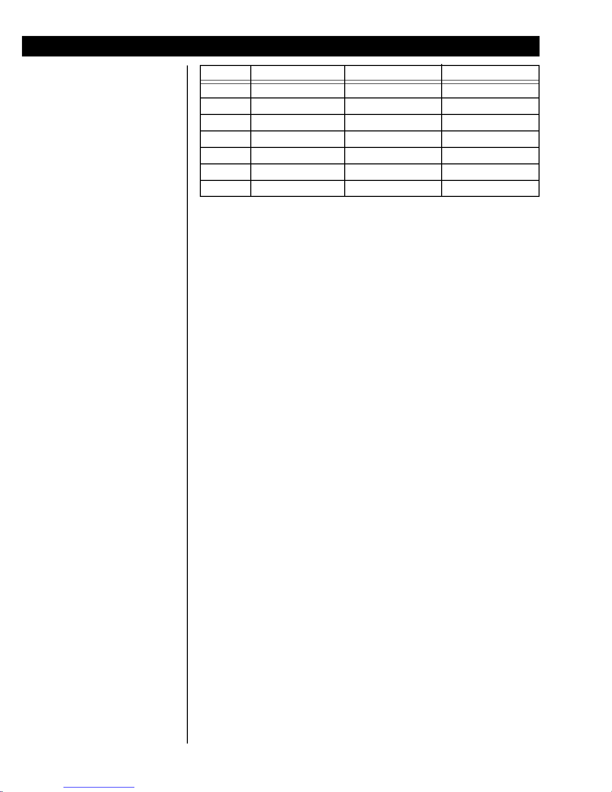
Specifications
Capacity and Dimensions
Construction
Display
Units of measure
Keys
Power
Model Capacity LB (kg) Dimensions Resolution LB (g)
3730LP 10 (5) 10.4” x 10.4” x 2.5” .002 (1)
3730LP 25 (10) 10.4” x 10.4” x 2.5” .005 (2)
3730LP 50 (25) 10.4” x 10.4” x 2.5” .01 (5)
3732LP 100 (50) 14” x 14” x 2.9” .02 (10)
3732LP 250 (100) 14” x 14” x 2.9” .05 (20)
3734LP 100 (50) 18” x 18” x 3.1” .02 (10)
3734LP 250 (100) 18” x 18” x 3.1” .05 (20)
Aluminum base on 10”x10” model or mild steel base on 14”x14” and 18”x18”
models. Stainless steel shroud.
Backlit LCD display with six .5” tall digits. Housed in a 6” aluminum alloy
extrusion. Display can be attached to base with supplied aluminum display
bracket and secured with magnetic strips. Can also be remotely mounted
with 7’ of included cable.
lb, kg, g or oz. Front panel switching between units of measure (Note: only
two units active at any one time).
Units, Print and Zero.
120 VAC ±10% - 15%, 60 Hz. (UL/CUL)
Internal resolution
Power supply
Overload
Battery recharge time
Output
Operating environment
Agencies
Options
100,000 internal counts of resolution.
Internally mounted on models 3732LP and 3734LP. Wall mounted on
model 3730LP.
Up to 200% of scale rated capacity.
6 hours when powered down.
Bidirectional RS-232 with selectable baud rates from 1200 to 19.2K.
41°F to 104°F (5°C to 40°C). 10 to 95% relative humidity, non-condensing.
NTEP C.O.C. # 02-069, CW&M AM#5507 (5000div class III)
Factory installed battery: Up to 20 hours of continuous operation with
backlight turned on. When used with the display backlight turned off or in
auto mode, battery operation is extended up to 75 hours of operation.
Internally mounted, sealed lead acid gel cell battery provides up to 500
discharge/recharge cycles. Battery fully recharges in 6 hours by plugging the
scale into an AC outlet. Scale can be used while recharging. (Not available
on 3730LP model)
Distributor installed battery kit – (Not available on 3730LP Models)
Auto power off – Two power saving modes can be configured to turn the
backlight off or shut down the scale after inactivity to preserve battery life.
Ball top kit – (Not available on 3730LP Models)
Display swivel bracket kit
12” pole display kit
Footswitch for zero or print (factory installed)– With 4 ft. or 10 ft. long
cable assembly.
230 VAC operation – 230 VAC ±10% - 15%, 50 Hz
4
3700LP Bench Scale Series User’s Manual
Page 5
Introduction
The 3700LP Series is made up of several sizes and capacities of low profile
bench scales. These scales have heavy duty bases, stainless steel, wraparound shrouds and easy to see and operate display panels that can be
mounted on the unit or remotely, by cable. See Specifications for all the
options and models which are available.
This manual covers the following:
• Introduction to the 3700LP family
• Unpacking and setup
• Front Panel
• Operation
• Maintenance
Major sections of the manual are separated by black bar headers as seen
above (Introduction). Subheadings appear in the left column along with
important notes, tips and warnings.
If you have any problems with your scale, contact your local Avery WeighTronix distributor.
Unpacking and Setup
Only plug this unit into a
properly grounded, easily
accessible outlet of the
proper voltage. Injury or
damage to the unit may
occur if the unit is not
properly grounded.
Unpack your 3700 scale and inspect it for shipping damage. Report any
damage to your shipping company immediately and save all packing materials.
Place the unit on a stable, level surface. Look at the bubble level under the
stainless steel shroud as you adjust the threaded feet to level the scale.
Tighten the jam nuts up against the scale base once the scale is level.
Plug the display cable into the proper connector on the back of the scale.
Plug the power cord into the proper connector on the back of the scale.
If your unit is battery powered, charge the battery for 6 hours and disconnect
from the charger before using the scale. Battery life depends on usage of
the backlight and other factors.
The 10” x 10” scales do not have the battery option.
If you have a printer or other peripheral device, plug it into the proper
connector on the back of the scale.
3700LP Bench Scale Series User’s Manual
5
Page 6
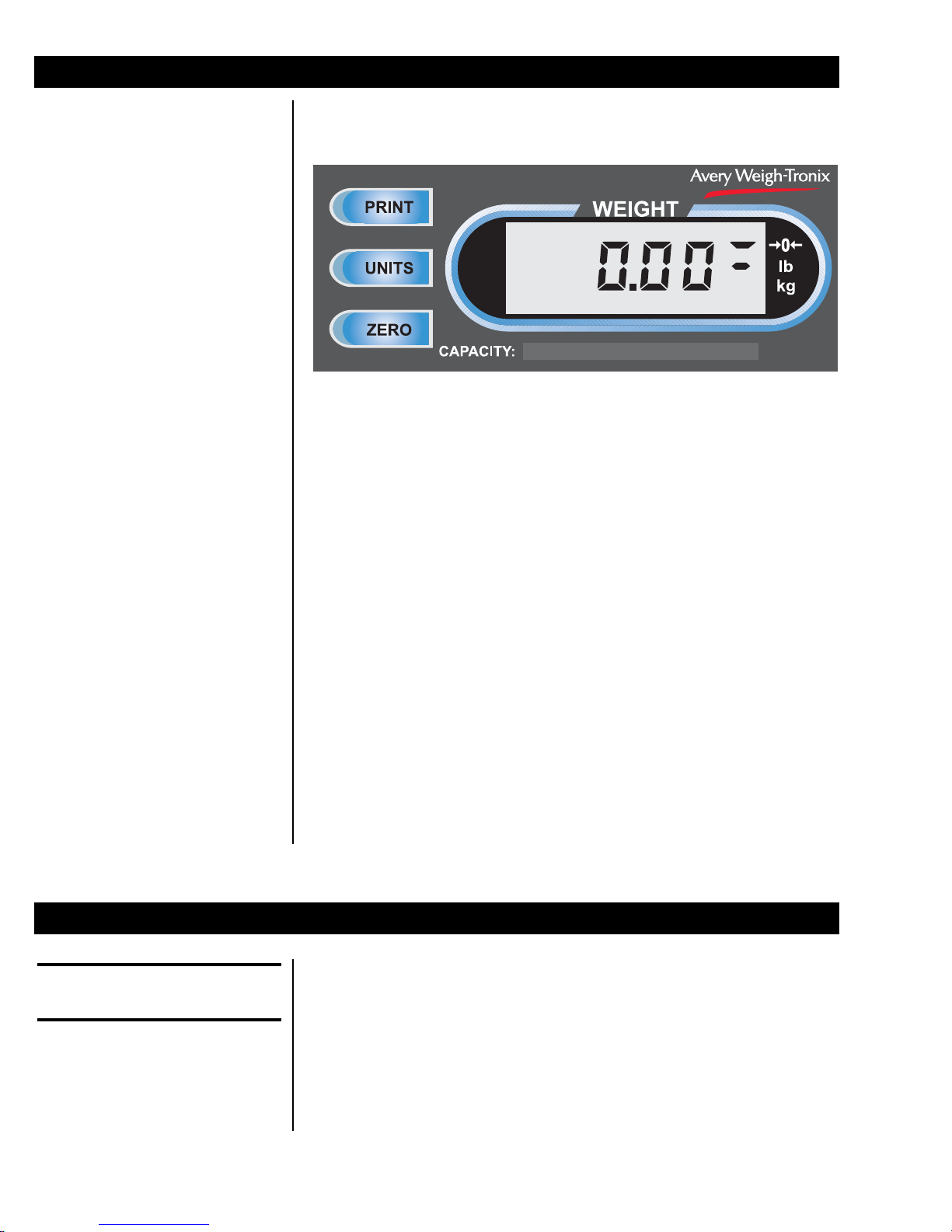
Front Panel
The front panel consists of the display window, annunciator labels, and three
operation keys; PRINT, UNITS, and ZERO. See Figure 1.
Figure 1
Front panel
The display has five LCD weight digits and annunciators. The display is
backlit for greater visibility.
The center-of-zero annunciator
lights up when the scale is
within ¼ graduation of zero.
Operation
Performing a
Weighment
The center-of-zero, lb and kg annunciator labels are indicated as active
when the annunciators appear to their left in the display window. In Figure 1,
the annunciators show the scale is at zero weight and in the lbs unit of
measure.
The key functions are listed below:
PRINT Press this key to send serial data to a peripheral printer or other
device. If there is motion on the scale, CANT is displayed and
no printing will occur.
UNITS Press this key to toggle between available units of measure. If
the scale is configured to limit the scale to just one unit of
measure, the display will show CANT if you try to switch the unit
of measure.
ZERO Press this key to zero the weight display. If there is motion on
the scale, CANT is displayed and the zero request is ignored.
To perform a weighment, follow these steps:
1. Remove all weight from the scale and press the ZERO key.
Display should show 0 weight.
2. Place the item to be weighed on the scale.
3. Remove the item and repeat steps 1 and 2 for each item.
6
3700LP Bench Scale Series User’s Manual
Display shows the weight.
Page 7

Printing Output
For detailed printing protocol
information, see the section
titled RS-232 Protocols.
If your system is configured for printing of weights and you have a printer
properly connected to the scale, the printer will print the weight information
either
• after the weight is stable or
• after the item is removed from the scale, depending on the configuration settings. See the Service Manual for information on configuring the
scale.
Output depends on the printer and paper/label stock being used. Figure 2
shows a sample printout on a papertape printer (such as the WP-234) when
time and date are installed. If time and date are not present in the printer,
just the weight and unit of measure are printed.
10/07/03
Serial Connector Pin-out
DE-9 Female Scale
Pin Name Direction
1. JMP 1 -
2. TXD OUT
3. RXD IN
4. JMP 1 -
5. SG -
6. JMP 1 -
7. JMP 2 -
8. JMP 2 -
9. NC -
Date information is supplied by
the printer, not by the 3700. If
your printer does not have date
capabilities, the printout will not
show the date.
28.01 lb
Figure 2
Papertape sample printout
Figure 3 shows a sample printout from a label printer (such as the Zebra LP-
2844) on 1.2" x .85" label stock. This sample shows the date. If your printer
is not equipped with time and date capability, the date will not be present.
Figure 3
Small label sample printout
(1.2" x .85")
3700LP Bench Scale Series User’s Manual
7
Page 8

Figure 4
Large barcode label sample printout
(4" x 2.25")
Figure 4 shows a sample printout with barcode on 4" x 2.25" label stock.
This sample shows time and date. If your printer is not equipped with time
and date, they will not be present.
Operation of the
Optional Footswitch
Sleep Mode and Power
Down Timer
If you have the optional footswitch attached to the scale you can use it to
zero the scale or print a weighment, depending on how the scale is configured.
To zero the scale with the footswitch, empty the scale and press the
footswitch. The scale display will show 0 weight.
To print a weighment with the footswitch, place the item on the scale, wait
for the weight to stabilize and press the footswitch. The printer will print the
weighment.
If the scale is equipped with the battery option, the scale can be shut off by
pressing and holding the ZERO key for approximately five seconds.
The sleep timer should only be used on battery equipped scales. The
SLEEP timer can be set to NONE (default for non-battery units), 5 (default
for battery equipped units), 30, or 60 minutes. If a value other then NONE
is chosen then after the selected time period with no scale or button activity
several electronic functions will go to sleep to save battery power. The
display will show SLEEP and pressing any key will wake-up the scale.
The power down timer, if configured, will shut off the scale completely after
approximately 1 hour of sleep. To power up the scale from this state you
must either press the ON button located near the connections on the back of
the scale or unplug and then plug-in the power cord.
8
3700LP Bench Scale Series User’s Manual
Page 9

Battery Information
Maintenance
RS-232 Protocols
The battery powered units must be charged prior to use. Plug in the AC cord
to charge an installed battery. A drained battery will charge in about six
hours.
With approximately one hour of use left in the battery, the display will flash
LOBAT every 15 seconds.
There is little to do to maintain this scale.
• Keep the platter clean
• Regularly check calibration with a test weight
• Do not use water on the base. A cloth dampened with cleaner is
sufficient for wiping the surface.
The serial data format is
- 1 Start bit
- 7 Data bits (8 with no parity)
- 1 Parity bit
- 1 Stop bit
Computer commands and scale
responses are upper and
lowercase character strings.
- (CR) is an ASCII carriage
return
- (LF) is an ASCII line feed
- (ETX) is an ASCII end of text
- x is a weight digit (0-9)
RS-232 Protocol
Tables
There are three types of RS-232 output protocol:
Type of Protocol Displayed as
1. Standard ProBench NCI (Default)
2. NCI Model 3835 3835
3. Model 8213 8213
See RS-232 Protocol Tables, with accompanying legend and notes, for
protocol code.
The default baud rate is 9600, 8 data bits, no parity.
Legend: The following symbols are used in protocol tables.
p ............................. Polarity of weight
“-” for negative
“ ” (space character for positive)
[CR] ........................ ASCII carriage return
[LF] ......................... ASCII line feed
[ETX] ...................... ASCII end of text
[HL]......................... H = high scale status byte. L = low scale status byte.
[STATUS] ............... Toledo scale status byte
[CONFIDENCE]...... Toledo confidence test status byte
3700LP Bench Scale Series User’s Manual
9
Page 10

Notes: Numbers 1 - 4 below are referenced in the protocol tables under
NOTES:
1. The decimal point position may be different depending on selected
capacity and division.
2. A space character is added to bring character count to the same as
capacities with a decimal point.
3. A status byte is sent if the scale is in motion, under zero, over capacity or
the scale is at center-of-zero.
ProBench Scale Status Byte Formats
High Order Byte [H]
BIT: 7 6 5 4 3 2 1 0
In motion
At zero
Not used
Not used
Always = 1
Always = 1
Always = 0
Parity bit
Low Order Byte [L]
BIT: 7 6 5 4 3 2 1 0
Under Cap.
Over Cap.
Not used
Not used
Always = 1
Always = 1
Always = 0
Parity
10
3700LP Bench Scale Series User’s Manual
Page 11

NCI Protocol Displayed as "NCI"
Command Possible Scale Response Units Notes
W<CR> <LF>XXX.XXlb<CR><LF>[HL]<CR><ETX> Pounds 1
<LF>XXX.XXkg<CR><LF>[HL]<CR><ETX> Kilograms 1
<LF>XXX.XXoz<CR><LF>[HL]<CR><ETX> Ounces 1
<LF>_XXXXg_<CR><LF>[HL]<CR><ETX> Grams 2
Z<CR> <LF>[HL]<CR><ETX> Zeros scale
S<CR> <LF>[HL]<CR><ETX> Scale Status
All other <LF>?<CR><ETX> Bad command
Model 8213 Protocol Displayed as "8213"
Command Possible Scale Response Units Notes
W <STX>XXX.XX<CR> Pounds 1
<STX>XXX.XX<CR> Kilograms 1
<STX>XXX.XX<CR> Ounces 1
<STX>0XXXXX<CR> Grams 2
<STX>?[STATUS]<CR> 3
H <STX>XXXX.XX<CR> Pounds 1
<STX>XXXX.XX<CR> Kilograms 1
<STX>XXXX.XX<CR> Ounces 1
<STX>0XXXXXX<CR> Grams 2
<STX>?[STATUS]<CR> 3
Z <STX>?[STATUS]<CR> Zeros scale
3700LP Bench Scale Series User’s Manual
11
Page 12

Model 3835 Protocol Displayed as "3835"
Command Possible Scale Response Units Notes
W<CR> <LF>p0XX.XXLB<CR>[HL]<ETX> Pounds 1
<LF>p0XX.XXKG<CR>[HL]<ETX> Kilograms 1
<LF>p0XX.XXOZ<CR>[HL]<ETX> Ounces 1
<LF>p00XXXXG_<CR>[HL]<ETX> Grams 2
Z<CR> No response Zeros scale
S<CR> <LF>[HL]<CR> Scale Status
All other <LF>?<CR> Bad command
12
3700LP Bench Scale Series User’s Manual
Page 13

Diagnostics Menu
You can skip from one menu
item to the next. Press the
ZERO key to scroll through the
list until you find the item you
want, then press UNITS to
access the test or information
There is a diagnostics menu that user’s may access to help diagnose scale
problems.
Follow these steps to access and move through the diagnostics menu
shown in Figure 4.
1 Press and hold the PRINT key until DIAG is displayed.
2. Press the UNITS key. . .
DISP is displayed. This is the display test.
3. Press the UNITS key to perform the display test. . .
Display shows DISP when the test is done.
4. Press the ZERO key to scroll to the next diagnostic menu item, RA. . .
RA is displayed. This stands for the RAM test. Press the UNITS
key to perform the test. PASS or FAIL will be briefly displayed,
then RA will be displayed.
5. Use the UNITS and ZERO keys and continue through the menu as
necessary for your diagnostic issue. The list on the next page lists each
item and what they mean.
Figure 4
Diagnostics menu structure
3700LP Bench Scale Series User’s Manual
13
Page 14

DISP Shows version and revision of program, followed by a segment
test and countdown.
RA Performs a nondestructive test of all locations of RAM in the
processor and displays PASS or FAIL.
RO Performs a checksum of all ROM locations in the processor.
This value is compared with a value stored in ROM and displays
PASS or FAIL.
I/O Install a loopback connector with transmit and receive jumped
together on the RS-232 output connector. The display will show
PASS or FAIL.
HRESA Displays ten times normal resolution with AZT enabled and the
most significant digit of weight not shown. Press TEST to stop
this test.
HRESN Displays ten times normal resolution with AZT disabled and
most significant digit of weight not shown. Press TEST to stop
this test.
CAP Displays the calibrated capacity and division size of the scale.
UNITS Displays the current unit of measure selection(s).
LOC-G Shows the local gravity compensation value.
CAL-G Shows the gravity compensation value for the Fairmont, MN
manufacturing site.
The following are viewable configuration settings. None can be
changed:
FILTR Filter setting - FAST, SLOW
BACLT Backlight setting - ON, OFF, AUTO
BAUD Baud rate setting - 1200 to 19.2K
PROT RS-232 protocol setting
AUTOP Autoprint setting - OFF, AUTO1, AUTO2
E-INP External input setting - ZERO or PRINT
SLEEP Sleep setting - NONE, 5, 30, 60 minutes
P-OFF Power off setting - ON, OFF
SEAL Seal setting - SEALED, UNSEALED
14
3700LP Bench Scale Series User’s Manual
Page 15

Installing the Display Mounting Bracket
Parts
Scales are shown disassembled for clarity only. They
do not have to be disassembled to install the brackets.
The display mounting kit includes the hardware necessary to attach the
remote display to the scale base. For the 100 to 250 lb capacity 14 x 14 inch
bases, use the bracket shown in Figure 5 (PN1067-17224).
Figure 5
Mounting bracket (100-250 lb, 14 x 14 inch base)
For the 10-50 lb, 10 x 10 inch bases, use the bracket shown in Figure 6.
Attach the two parts with supplied screws, lockwashers and nuts before
continuing to instructions on next page.
Figure 6
Mounting bracket (10-50 lb, 10 x 10 inch bases)
3700LP Bench Scale Series User’s Manual
15
Page 16

Installation
Be sure there is no interference
with the movement of the
weighing platform.
For both styles of brackets, follow these steps to install the mounting bracket
and attach the display:
1. Disconnect the power and display cables and turn the scale upside
down.
2. Place a cable twisty (supplied on original display assembly) thru the two
holes on the vertical side of the display bracket so that the ends point
toward the back of the sloped display mounting surface. Twist once to
hold in place until ready to secure the excess display cable. (See
Figures 5 and 6 for mounting drawings.)
3. Place the display mounting bracket on the scale base, aligning the holes
in the bracket with the proper holes in the baseplate.
4. Secure the bracket to the baseplate with the two 10-32 screws provided
(100-250 lb bases) or the feet (10-50 lb bases).
5. Pull the protective paper from the back of the two magnetic strips. Apply
one to the center of the mounting bracket and the other to the center of
the back of the display.
6. Reconnect the display cable. Route the cable towards the front of the
scale away from the channel and loop in the cable clips located in
appropriate places underneath the scale base.
7. With minimal slack in the cable, secure the remaining excess cable
within the v-shaped valley of the bracket and secure with the tie wrap.
Be sure that there is sufficient cable available to allow the display to
attach to the front of the bracket with the magnetic strips.
8. Inspect the display cable and twisty to insure there is no interference
with the live weighing portion of the scale.
9. Return the scale to normal operating position.
10. Position the display housing on the bracket so the two magnetic strips
connect. See Figure7.
Figure 7
Mounting the display
11. Reconnect power to the scale and check for proper operation.
16
3700LP Bench Scale Series User’s Manual
Page 17

3700LP Bench Scale Series User’s Manual
17
Page 18

18
3700LP Bench Scale Series User’s Manual
Page 19

3700LP Bench Scale Series User’s Manual
19
Page 20

Weigh Bar® is a registered trademark
of Avery Weigh-Tronix and may be
registered in certain jurisdictions.
All brands and product names used
within this document are trademarks
or registered trademarks of their respective holders.
Avery Weigh-Tronix USA
1000 Armstrong Dr.
Fairmont, MN 56031 USA
Telephone: 507-238-4461
Facsimile: 507-238-4195
e-mail: industrial@weigh-tronix.com
www.wtxweb.com
Avery Weigh-Tronix UK
Foundry Lane
Smethwick, West Midlands
England B66 2LP
Tel: +44 870 90 34343
Fax: +44 121 224 8183
Email: info@awtxglobal.com
Web site:www.averyweigh-tronix.com
Avery Weigh-Tronix Canada, ULC
217 Brunswick Boulevard
Pointe Claire, QC H9R 4R7 Canada
Telephone: 514-695-0380
Toll free: 800-561-9461
Facsimile: 514-695-6820
www.weigh-tronix.ca
 Loading...