

Page 1
Model 2060
Universal Weight Indicator
User Instructions
AWT35-501506
Issue AB
Page 2

Avery Weigh-Tronix is a trademark of the Illinois Tool Works group of companies whose ultimate parent company is
Illinois Tool Works Inc (“Illinois Tool Works”). Copyright © 2018 Illinois Tool Works. All rights reserved.
No part of this publication may be reproduced by making a facsimile copy, by the making of a copy in three dimensions of a two-dimensional
work and the making of a copy in two dimensions of a three-dimensional work, stored in any medium by electronic means, or transmitted in
any form or by any means, including electronic, mechanical, broadcasting, recording or otherwise without the prior written consent of the
copyright owner, under license, or as permitted by law.
This publication was correct at the time of going to print, however Avery Weigh-Tronix reserves the right to alter without notice the
specification, design, price or conditions of supply of any product or service at any time.
Model 2060_u_en_501506.book
Page 3

Table of Contents
Chapter 1 General Information and Warnings ........................................................................................ 7
About this Manual ..............................................................................................................7
Text Conventions ........................................................................................................7
Special Messages .......................................................................................................7
Installation ....................................... .................................... ...................................... .........8
Safe Handling of Equipment with Batteries .................................................................8
Routine Maintenance .........................................................................................................9
Cleaning the Machine ........................................................................................................9
Training ..................................... ................................................................ .........................9
Sharp Objects .............................................................................. .... ... ... ..........................10
FCC and EMC Declarations of Compliance ..................................................................... 10
Declaration of Conformity ......... ... ... ... .... ... ....................................................................... 11
Chapter 2 Overview .................................................................................................................................12
Front Panel and Keys ......................................................................................................12
Front Panel Keys .......................................................................................................13
Home Screen ...................................................................................................................14
Adjusting screen contrast .................................................................................................14
Using the alphanumeric keypad .......................................................................................14
Menus ..............................................................................................................................14
Standard Print Formats ....................................................................................................15
Chapter 3 Installation .............................................................................................................................. 17
Mounting the Model 2060 ................................................................................................17
Instructions for V mount ............................................................................................17
Instruction for Ram Mount .........................................................................................17
Cable Connections and Power Requirements .................................................................18
AWT05-509201 4+ Pin Amp Bottom Plate ................................................................18
AWT05-509202 4x 5Pin AWT Bottom Plate ..............................................................18
Connectors ................................................................................................................ 19
Routing the Scale Interface Cable ...................................................................................20
Connecting to a Convenience Outlet ...............................................................................20
Power Connections - Battery ...........................................................................................21
Wiring 2060 Indicator to Equipment Power Systems .................................... ...................23
12 Volt Power Systems (one and two 12 V batteries) ...............................................23
24 Volt Power Systems .............................................................................................24
Grounded Power Systems ........................................................................................24
Power Connections - AC ..................................................................................................25
Optional Communications Connections .... .......................................................................26
Additional Connectors ........................ ... ....................................................................27
I/O Connector Pins (9 pin connector) ........................................................................27
Chapter 4 Quick Start Calibration Guide ............................................................................................... 28
Calibrate the 2060 with a Standard Configuration Number ............................................. 28
Determine the Configuration Number ........................... ...................... ....................... 28
Configuration Codes ..................................................................................................30
Enter the Configuration Code Number Parameter (Cfg Num) ................................... 31
Configuration Code Numbers for Common Applications: ............................. .............32
Custom Configuration Number for AWTX Weigh Bars ....................................................33
Determine Configuration Number .................................... ....................... ...................33
Determine Custom Calibration Number ....................................................................34
Custom Number Table .............................................................................................. 34
Enter Configuration Code Number (Cfg Num) .......................................................... 38
Enter Custom Configuration Number (Cust.Cfg) ................ .......................................38
Custom Configuration Number Calibration ............ .... ... ... ... ... .... ... ... ..........................39
Model 2060 User Instructions 3
Page 4

Configuring the 2060 for Other Brand Weigh Bars and Loadcells ...................................40
Custom Calibration Number ......................................................................................40
Chapter 5 Menus ............................................ ................................................... .......................................42
Accessing the menus .......................................................................................................42
Menu Navigation ......................................................................................................43
Exiting the Menus ............................................................................................................43
User menu ................................................... ... .... ...................................... .... ... ... .............45
The User submenu ....................................................................................................45
The About submenu ..................................................................................................46
The Audit submenu ...................................................................................................47
Diag menu .................................... ... ... ....................................... ... .... ... .............................48
Scale .........................................................................................................................48
Cur.Zero .................................................................................................................... 48
Display ...................................... ....................... ...................... ....................... .............49
Buttons ...................................................................................................................... 49
Ports ..........................................................................................................................49
Inputs .................................. ................... .................... ................... ................... ..........49
Outputs ..................................... .................................................... .............................50
Options ...................................................................................................................... 50
Logs ....................................... ....................... ...................... ....................... ................51
BSQ .................................... ................................................... .................................... 51
DigJbox .....................................................................................................................51
Admin menu .....................................................................................................................52
Calibrate .................................... ...... ....... ...... ....... ...... ....... ... ...... ....... ...... ....... ...... ...... .......54
Zero procedure ...................... ... ... .... ...................................... .... ... ... ... .... ... ................54
Span procedure .........................................................................................................55
Linearity (Linear) procedure ......................................................................................56
Build Up procedure ....................................................................................................56
Input procedure (key-in calibration) ....................... .................................................... 56
Gravity procedure ..................... ... .... ... ....................................... ... ... ... .... ... ... .............57
Display procedure .....................................................................................................57
Cal Unit procedure ....................................................................................................57
Print procedure ...................... ... ... .... ...................................... .... ... ... ... .... ... ................58
Cfg Num ....................................................................................................................58
Cust.Cfg ....................................................................................................................58
Span Adj ....................................................................................................................58
Scale menu ........... .... ... ....................................... ... ... ... ....................................... ... ... .......58
Capacty ..................................................................................................................... 59
Dvision .....................................................................................................................59
Units ..........................................................................................................................59
Stable ........................................................................................................................60
AZT ..................................... ................... .................... ................... ................... ..........60
Filter ..........................................................................................................................60
Ranges ...................................................................................................................... 62
2,3 Range .................... .... ...................................... .... ...................................... ... .......62
Type ..........................................................................................................................64
Roc ............................................................................................................................64
DigJbox .....................................................................................................................64
Traffic ........................................................................................................................64
System menu ........ .... ...................................... .... ... ... ....................................... ... ... ..........65
Site ............................................................................................................................65
Display ...................................... ....................... ...................... ....................... .............66
Buttons ...................................................................................................................... 67
D-Vals .................................... ....................... ...................... ....................... ................67
Tare ...........................................................................................................................69
Config ........................................................................................................................ 69
4 Model 2060 User Instructions
Page 5

Archive ......................................................................................................................70
Serial .........................................................................................................................70
Update ...................................... .................................................... .............................70
Password ..................................... ....................... ....................... ...................... ..........71
Z-Lock .......................................................................................................................71
Beeper ...................................... .................................................... .............................71
Num Scl .....................................................................................................................71
Ports menu .......................................................................................................................72
Serial .........................................................................................................................72
Enet ...........................................................................................................................73
Protcl .........................................................................................................................75
P.F. Edit ................. ... ....................................... ... ... .... ...................................... ... .... ...77
PLC ...........................................................................................................................77
Printer ....................................... ....................................................... ..........................79
File ...................................... ...................... .................... ...................... .......................79
Options ...................................................................................................................... 81
Opt232 ...................................... ....................... ...................... ....................... .............81
USB ........................................................................................................................... 81
Chapter 6 Application menu ................................................................................................................... 82
Accessing the Application menu ......................................................................................83
Auto Settings ....................................................................................................................84
Totals Settings ....................................... ... ... ....................................... ... ... .... ...................85
App Settings ................................. ... ... ....................................... ... .... ... .............................85
App Info .................................. ... ... ....................................... ...................................... .......86
Model 2060 User Instructions 5
Page 6

6 Model 2060 User Instructions
Page 7
1 General Information and Warnings
1.1 About this Manual
This manual is divided into chapters by th e chapter numb er and the large text at the top of a p age. Subsections
are labeled using the 1.1 and 1.1.1 convention. The names of the chapter and the next subsection level appear
at the top of alternating pages of the manual to re mind you of where you are in the manual. The manual name
and page numbers appear at the bottom of the pages.
1.1.1 Text Conventions
Key names are shown in bold and reflect the case of the key being described. If a key has dual functions, the
function is shown first followed by the key name in parentheses and in bold, such as in these examples: F1,
SELECT, PRINT, etc.
Displayed messages appear in bold italic type and reflect the case of the displayed message.
1.1.2 Special Messages
Examples of special messages you will see in this manual are defined below. The heading words have specific
meanings to alert you to additional information or the relative level of hazard.
DANGER!
THIS IS A DANGER SYMBOL.
DANGER MEANS THAT FAILURE TO FOLLOW SPECIFIC PRACTICES
OR PROCEDURES WILL CAUSE INJURY OR DEATH.
ELECTRICAL WARNING!
THIS IS AN ELECTRICAL WARNING SYMBOL.
ELECTRICAL WARNINGS MEAN THAT FAILURE TO FOLLOW
SPECIFIC PRACTICES OR PROCEDURES MAY RESULT IN
ELECTROCUTION, ARC BURNS, EXPLOSIONS OR OTHER HAZARDS
THAT MAY CAUSE INJURY OR DEATH.
WARNING!
This is a Warning symbol.
Warnings mean that failure to follow specific practices and procedures may
have major consequences such as injury or death.
CAUTION!
This is a Caution symbol.
Cautions give information about procedures that, if not observed, could result
in damage to equipment or corruption to and loss of data.
Model 2060 User Instructions 7
Page 8

NOTE: This is a Note symbol. Notes give additional and important information, hints
and tips that help you to use your product.
1.2 Installation
NO USER SERVICEABLE PARTS. REFER TO QUALIFIED SERVICE
PERSONNEL FOR SERVICE.
1.2.1 Safe Handling of Equipment with Batteries
CAUTION: Danger of explosion if battery is incorrectly replaced. Replace only
with the same or equivalent type recommended by the manufactur er. Dispose
of used batteries according to the manufacturer’s instructions.
ATTENTION: Il y a danger d'explosion s'il y a remplacement incorrect de la
batterie, remplacer uniquement avec une batterie du même type ou d'un type
équivalent recommandé par le constructeur. Mettre au rebut les batteries
usagées conformément aux instructions du fabricant.
8 Model 2060 User Instructions
Page 9
1.3 Routine Maintenance
IMPORTANT: This equipment must be routinely checked for proper operation
and calibration.
Application and usage will determine the frequency of calibration required for
safe operation.
ELECTRICAL WARNING!
ALWAYS TURN OFF THE MACHINE AND ISOLATE FROM THE POWER
SUPPLY BEFORE STARTING ANY ROUTINE MAINTENANCE TO
AVOID THE POSSIBILITY OF ELECTRIC SHOCK.
CAUTION: Do not weld on or near the 3060 or any part of the scale system such
as Weigh Bars. Excessive heat and / or high currents may cause internal
damage. Physically remove the 2060 from any equipment it is mounted to and
disconnect it from the power source. Mak e ground connectio n as far away from
any scale part (cables, Weigh Bar, etc.) as possible.
1.4 Cleaning the Machine
Table 1.1 Cleaning DOs and DON’Ts
DO DO NOT
Wipe down the outside of standard products
with a clean cloth, moistened with water and
a small amount of mild detergent
Spray the cloth when using a proprietary
cleaning fluid
Attempt to clean the inside of the machine
Use harsh abrasives, solvents, scouring cleaners or
alkaline cleaning solutions
Spray any liquid directly on to the display windows
1.5 Training
Do not attempt to operate or complete any procedure on a machine unless you have received the appropriate
training or read the instruction books.
To avoid the risk of RSI (Repetitive Strain Injury), place the machine on a surface which is ergonomically
satisfactory to the user. Take frequent breaks during prolonged usage.
Model 2060 User Instructions 9
Page 10

1.6 Sharp Objects
Do not use sharp objects such as screwdrivers to operate the keys.
1.7 FCC and EMC Declarations of Compliance
United States
This equipment has been tested and found to comply with the limits for a Class A digital device, pursuant to Part 15 of the FCC Rules.
These limits are designed to provide reasonable protection against harmful interference when the equipment is operated in a
commercial environment. This equipment generates, uses, and can radiate radio frequency energy and, if not installed and used in
accordance with the instruction manual, may cause harmful interference to radio communications. Operation of this equipment in a
residential area is likely to cause harmful interference in which case the user will be required to correct the interference at his own
expense.
Canada
This digital apparatus does not exceed the Class A limits for radio noise emissions from digital apparatus set out in the Radio
Interference Regulations of the Canadian Department of Communications.
Le présent appareil numérique n’émet pas de bruits radioélectriques dépassant les limites applicables aux appareils numériques de
la Classe A prescrites dans le Règlement sur le brouillage radioélectrique edicté par le ministère des Communications du Canada.
European Countries
WARNING: This is a Class A product. In a domestic environment, this product may cause radio interference in which the user may be
required to take adequate measures.
10 Model 2060 User Instructions
Page 11
1.8 Declaration of Conformity
EN
EU
Declaration of
Conformity
Name and address of the manufacturer:
Avery Weigh-Tronix
1
Foundry Lane
Smethwick
West Midlands
B66 2LP
ENGLAND
This declaration of conformity is issued under the sole
responsibility of the manufacturer
Object of the declaration:
2060 / M2060
RD60M
RCV60-CE
The object of the declaration described above is in conformi-
ty with the relevant Union harmonisation legislation:
Applicable Directives Harmonised
standards
or other technical
specifications
Additional information:
Note
1
:
ITW Ltd trading as Avery Weigh-Tronix
Reg. Office : Nexus House, Station Road, Egham,
Surrey, TW20 9LB, England
Signed for and on behalf of:
Avery Weigh-Tronix
at
1000 Armstrong Drive, Fairmont, MN, 56031-1439,
USA
on
2017-05-08 K.Detert
Global Head of R&D
Model / Type:
2060/RD60/RCV60-CE
2014/30/EU
Electromagnetic Compatibility
EN61000-6-1:2007
EN61000-6-4:2007
EN14982:2009
2014/35/EU
Electrical equipment designed for use
within certain voltage limits
EN 60950–1 : 2006
+A2:2013
76501-556 Issue
2
DE
EU-
Konformitätserklärung
Name und Anschrift des Herstellers:
Avery Weigh-Tronix
1
Foundry Lane
Smethwick
West Midlands
B66 2LP
ENGLAND
Die alleinige Verantwortung für die Ausstellung dieser Kon-
formitätserklärung trägt der Hersteller.
Gegenstand der Erklärung:
2060 / M2060
RD60M
RCV60-CE
Der oben beschriebene Gegenstand der Erklärung erfüllt die
einschlägigen Harmonisierungsrechtsvorschriften der Union:
Angewandte Richtlinien Harmonisierte
Normen oder
sonstigen
technischen
Spezifikationen
Zusatzangaben:
Anmerkung
1
:
ITW Ltd Handel als Avery Weigh-Tronix
Sitz: Nexus House, Station Road, Egham,
Surrey, TW20 9LB, England
Unterzeichnet für und im Namen von:
Avery Weigh-Tronix
bei
1000 Armstrong Drive, Fairmont, MN, 56031-1439,
USA
am
2017-05-08 K.Detert
Globaler Leiter von
Forschung und Entwicklung
Modell / Typen:
2060/RD60/RCV60-CE
2014/30/EU
Elektromagnetische Verträglichkeit
EN61000-6-1:2007
EN61000-6-4:2007
EN14982:2009
2014/35/EU
Elektrischer Betriebsmittel zur
Verwendung innerhalb bestimmter
Spanungsgrenzen
EN 60950–1 : 2006
+A2:2013
FR
DéclaraƟonUE
de
Conformité
Nom et adresse du fabricant :
Avery Weigh-Tronix
1
Foundry Lane
Smethwick
West Midlands
B66 2LP
ANGLETERRE
La présente déclaration de conformité est établie sous la
seule responsabilité du fabricant.
Objet de la declaration:
2060 / M2060
RD60M
RCV60-CE
L’objet de la déclaration décrit ci-dessus est conforme à la
législation d’harmonisation de l’Union applicable:
Les directives en vigueur Les normes
harmonisées ou
d’autres
spécifications
techniques
Informations complémentaires:
Nota
1
:
ITW Ltd exerçant également sous le nom de Avery Weigh-
Tronix
Siège soc ial: Nexus House, Station Road, Egham,
Surrey, TW20 9LB, Angleterre
Signé par et au nom de:
Avery Weigh-Tronix à 1000 Armstrong Drive, Fairmont, MN, 56031-1439,
USA
le
2017-05-08 K.Detert
Responsable Mondial de la
Recherche et du Développement
Modèle / Type:
2060/RD60/RCV60-CE
2014/30/UE
Compatibilité Électromagnétique
EN61000-6-1:2007
EN61000-6-4:2007
EN14982:2009
2014/35/UE
Matériel électrique destiné à être
employé dans certaines limites de
tension
EN 60950–1 : 2006
+A2:2013
NL
EU-
Conformiteitsverklar-
ing
Naam en adres van de fabrikant :
Avery Weigh-Tronix
1
Foundry Lane
Smethwick
West Midlands
B66 2LP
ENGELAND
Deze conformiteitsverklaring wordt verstrekt onder volledige
verantwoordelijkheid van de fabrikant.
Voorwerp van de verklaring:
2060 / M2060
RD60M
RCV60-CE
Het hierboven beschreven voorwerp is in overeenstemming
met de desbetreffende harmonisatiewetgeving van de Unie:
Toepasselijke richtlijnen Geharmoniseerde
standaarden
of andere
technische
specificaties
Aanvullende informatie:
Noot
1
:
ITW Ltd trading als Avery Weigh-Tronix
Zetel: Nexus House, Station Road, Egham,
Surrey, TW20 9LB, England
Ondertekend voor en namens:
Avery Weigh-Tronix
bij
1000 Armstrong Drive, Fairmont, MN, 56031-1439,
VS
op
2017-05-08 K.Detert
Wereldwijd Hoofd van Onderzoek en
Ontwikkeling
Model / Type:
2060/RD60/RCV60-CE
2014/30/EU
Elektromagnetische compatibiliteit
EN61000-6-1:2007
EN61000-6-4:2007
EN14982:2009
2014/35/EU
Elektrisch materiaal bestemd voor
gebruik binnen bepaalde span-
ningsgrenzen
EN 60950–1 : 2006
+A2:2013
IT
Dichiarazione
di
Conformità UE
Nome e indirizzo del fabbricante:
Avery Weigh-Tronix
1
Foundry Lane
Smethwick
West Midlands
B66 2LP
INGHILTERRA
La presente dichiarazione di conformità è rilasciata sotto la
responsabilità esclusiva del fabbricante.
Oggetto della dichiarazione:
2060 / M2060
RD60M
RCV60-CE
L’oggetto della dichiarazione di cui sopra è conforme alla
pertinente normativa di armonizzazione dell’Unione:
Direttive applicabili Arm onizzato
standard
o altre specificazioni
tecniche
Informazioni supplementari:
Nota
1
:
ITW Ltd trading come Avery Weigh-Tronix
Sede dell' ufficio: Nexus House, Station Road, Egham,
Surrey, TW20 9LB, England
Firmato a nome e per conto di:
Avery Weigh-Tronix a 1000 Armstrong Drive, Fairmont, MN, 56031-1439,
U.S.A.
su
2017-05-08 K.Detert
Responsabile Globale della Ricerca e
Sviluppo
Modello / Tipo:
2060/RD60/RCV60-CE
2014/30/UE
Compatibilità elettromagnetica
EN61000-6-1:2007
EN61000-6-4:2007
EN14982:2009
2014/35/UE
Materiale elettrico destinato a essere
adoperato entro taluni limiti di ten-
sione
EN 60950–1 : 2006
+A2:2013
ES
DeclaraciónUE
de
Conformidad
Nombre y dirección del fabricante
Avery Weigh-Tronix
1
Foundry Lane
Smethwick
West Midlands
B66 2LP
INGLATERRA
La presente declaración de conformidad se expide bajo la
exclusiva responsabilidad del fabricante.
Objeto de la declaración:
2060 / M2060
RD60M
RCV60-CE
El objeto de la declaración descrita anteriormente es
conforme con la legislación de armonización pertinente de la
Unión:
Directivas aplicables Normas
armonizadas u
otras
especificaciones
técnicas
Información adicional:
Nota
1
:
ITW Ltd trading as Avery Weigh-Tronix
Oficina registrada: Nexus House, Station Road, Egham,
Surrey, TW20 9LB, Angleterre
Firmado en nombre de:
Avery Weigh-Tronix
en
1000 Armstrong Drive, Fairmont, MN, 56031-1439,
EE.UU
el
2017-05-08 K.Detert
Jefe Global de Investigación y
Desarrollo
Modelo / Tipo:
2060/RD60/RCV60-CE
2014/30/UE
Compatibilidad electromagnética
EN61000-6-1:2007
EN61000-6-4:2007
EN14982:2009
2014/35/UE
Material eléctrico destinado a utiliz-
arse con determinados límites de
tensión
EN 60950–1 : 2006
+A2:2013
Model 2060 User Instructions 11
Page 12
2Overview
2060
1 2
ABC
3
DEF
4
GHI
5
JKLJKL
6
MNO
7
PQRS8TUV
9
WXYZ
CLEAR
0
-#:,%
F1 F2 F3 F4 F5
HOLD
TARE ZEROPRINT
HOMEHOLDHOLD
GROSS/NET
BACK EN TER
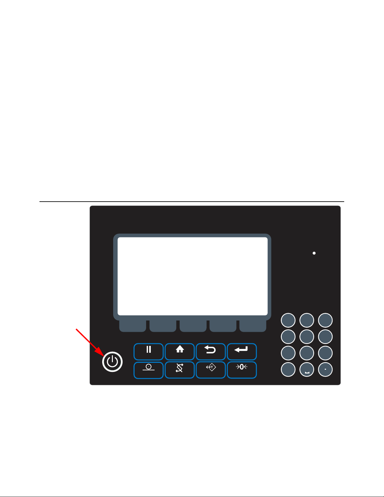
Power key
This manual covers the installation, conne ctions and configuration of the Model 2060
indicator.
The 2060 can connect to USB flash drives, printers, remote displays, computers and
other peripheral devices.
Communications- Two standard RS-232 with optional third bi-directional serial ports
w/selectable output formats – Standard, Broadcast, T ransfer Data Module (TDM).
Standard Connectivity - USB 9-pin Amp Input/Output Connector.
Optional Connectivity- Internal WiFi, Internal ZigBee point to point wireless, RM 110
Bluetooth, RS 232 peripheral interface, Ethernet Transmitter/Receiver, Third RS-232
Port.
TTL Inputs- Three programmable inputs (Std, Zero Clear, Hold, or Print).
Outputs- Two setpoint outputs, open collector design.
2.1 Front Panel and Keys
Figure 2.1 2060 Front Panel
Press the Power key to turn the unit on and press and hold the key for three seconds
to turn the unit off. The display will ask if you are sure. Use the up and down arrow keys
to highlight your answer and press the Enter (F3) key to confirm.
Model 2060 User Instructions 12
Page 13

2.1.1 Front Panel Keys
TARE
ENTER
PRINT
HOME
ZERO
BACK
HOLD
HOLDHOLD
GROSS/NET
1 2
ABC
3
DEF
4
GHI
5
JKL
JKL
6
MNO
7 8
TUV
9
CLEAR
0
The 2060 front panel shown in Figure 2.1 consists of the keys and the display.
Never press a key with anything but your finger. Damage to the overlay may result if
sharp or rough objects are used.
The functions of each key on the front panel are listed below.
Press to perform a tare function or prompts for a keyboard
tare, if enabled.
Press to toggle between Gross, Net, Tare and any other
active display values.
Press to send information to a peripheral device (printer,
computer or other serial device module).
Press in any mode to return to home screen or hold down for
3 seconds to access password screen.
Zeros the scale.
Press to back up one screen.
Press to hold a weight.
Press to toggle between the Gross and Net weight.
F1 - F5 Press these keys to select application specific choices.
Use the numeric keypad to enter numbers and letters in the
appropriate screens. Press the CLEAR key to clear the last
entry.
Model 2060 User Instructions 13
Page 14
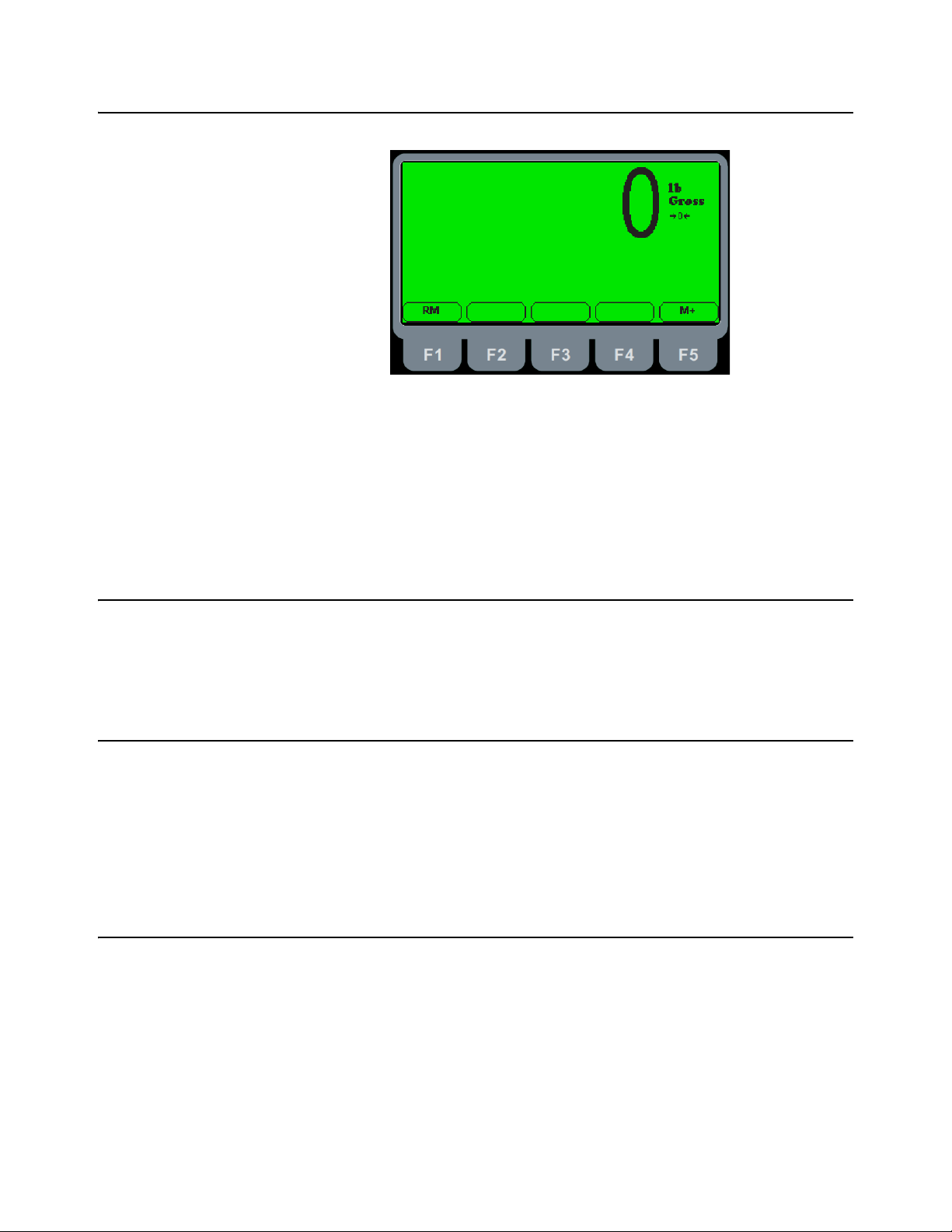
2.2 Home Screen
The home screen has two softkeys, explained below:
RM (F1) Press this key to access a memory channel, so the indicator is ready for
M+ (F5) Press this key to accumulate weights in the active memory channel.
Figure 2.2 Home Screen
accumulations into that channel.
2.3 Adjusting screen contrast
To decrease the screen contrast press and hold the HOLD key and repeatedly press
the TARE key . To increase the contrast, press and hold the HOLD key an d repeatedly
press the ENTER key.
2.4 Using the alphanumeric keypad
Use the alphanumeric keypad to enter numbers and words when prompted by the
indicator. The action is similar to using a cell phone to select the number or letter. A
rapid succession of presses will scroll through the number on the key and then the
letters, starting with upper case and then lower case. The decimal key scrolls through
the negative sign, pound sign, colon, comma and percent sign. The 0 key toggles
between 0 and a space.
2.5 Menus
Menus used to configure the 2060 are accessed with passwords. See Menus on page
42 for a complete overview of each menu and how to navigate through them.
14 Model 2060 User Instructions
Page 15

2.6 Standard Print Formats
G: 32010 lb
G: 32010 lb
T: 16010 lb
N: 16000 lb
04-26-2006
03:02:47
G: 32010 lb
04-26-2006
03:02:47
G: 32010 lb
T: 16010 lb
N: 16000 lb
32010
The Model 2060 has 10 available print formats. See the examples below.
Format 0
Format 1
Format 2
Format 3 (default)
Format 4
Model 2060 User Instructions 15
Page 16

Format 5
32010 , 16010 , 16000
04-26-2006,03:02:47, 32010
04-26-2006,03:02:47, 32010 ,
16010 , 1600
N: 16000 lb
04-26-2006
03:02:47
N: 16000 lb
Format 6
Format 7
Format 8
Format 9
16 Model 2060 User Instructions
Page 17
3 Installation
The following section will cover installing the Model 2060 and cable connections.
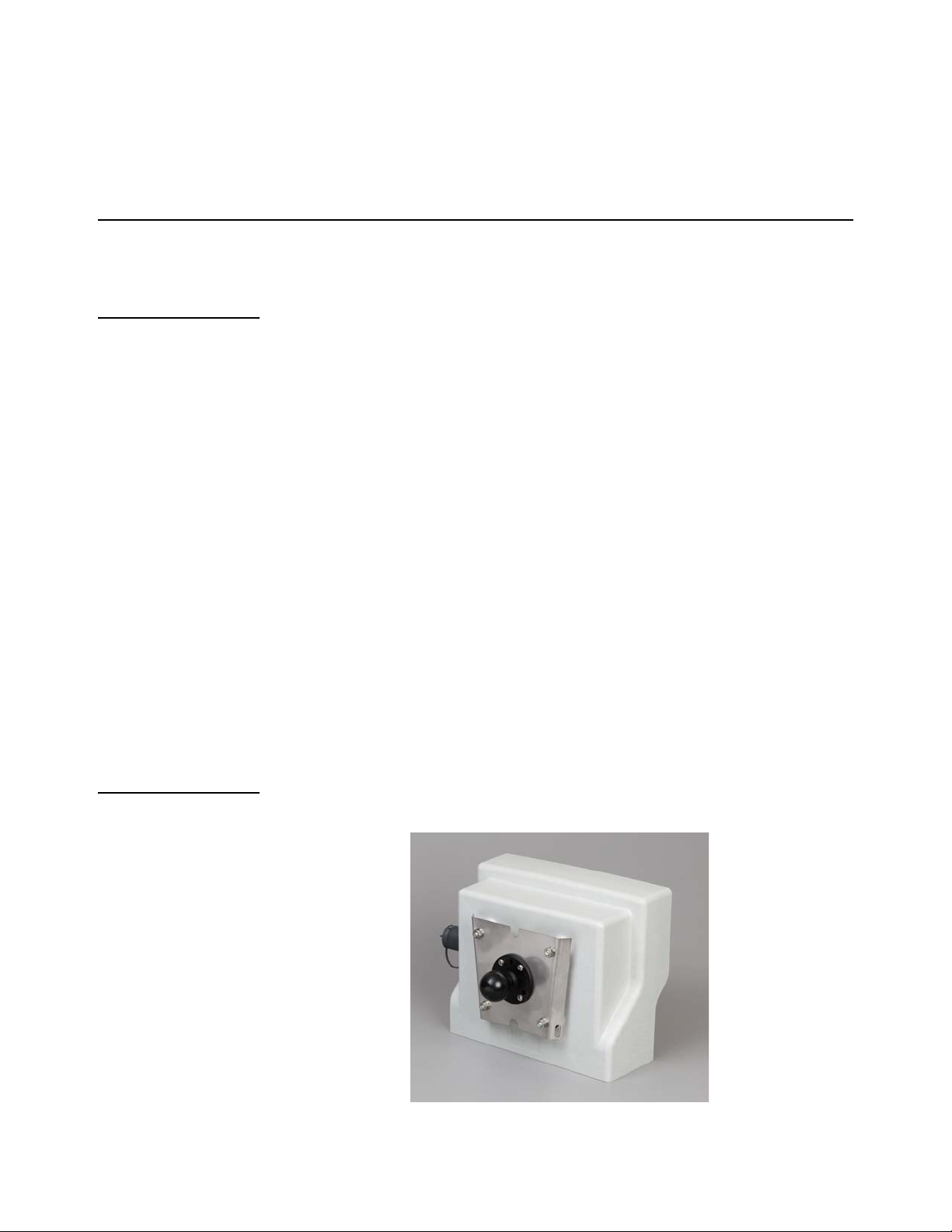
3.1 Mounting the Model 2060
The Model 2060 mounts on a quick-detach V bracket or a 1.5" Ram Mount.
3.1.1 Instructions for V mount
Weld or bolt the quick-detach bracket into place, as follows:
1. Choose a mounting location that is
l convenient for operation of the indicator, and
l protected from moving parts or from other moving machinery
2. Hold the indicator at the proposed mounting location, and verify that the
display is legible and the controls accessible.
3. Position the quick-detach bracket with the wider end at the top, mark the
desired mounting location. If bolting, use the quick-detach bracket as a
template and mark and drill holes.
4. Weld or bolt the quick-detach bracket at the appropriate location. If bolting,
use double nuts or self-locking nuts to protect both indicator and machinery.
CAUTION: Do not weld on or near a Weigh Bar. Excessive heat or high
currents may cause internal damage.
5. Insert the indicator bracket into the quick-detach bracket and push it down into
place.
6. For mobile applications, wrap and twist a strong wire or zip tie around the
indicator bracket and the quick-detach bracket to stabilize the mounting.
3.1.2 Instruction for Ram Mount
1. Order the Ram Mount Kit PN AWT05-508626.
2. Take nuts holding V bracket on 2060 off.
Model 2060 User Instructions 17
Page 18
3. Bolt one of the 2.5" Ram Mount bases onto the 2060 V mount bracket. It is
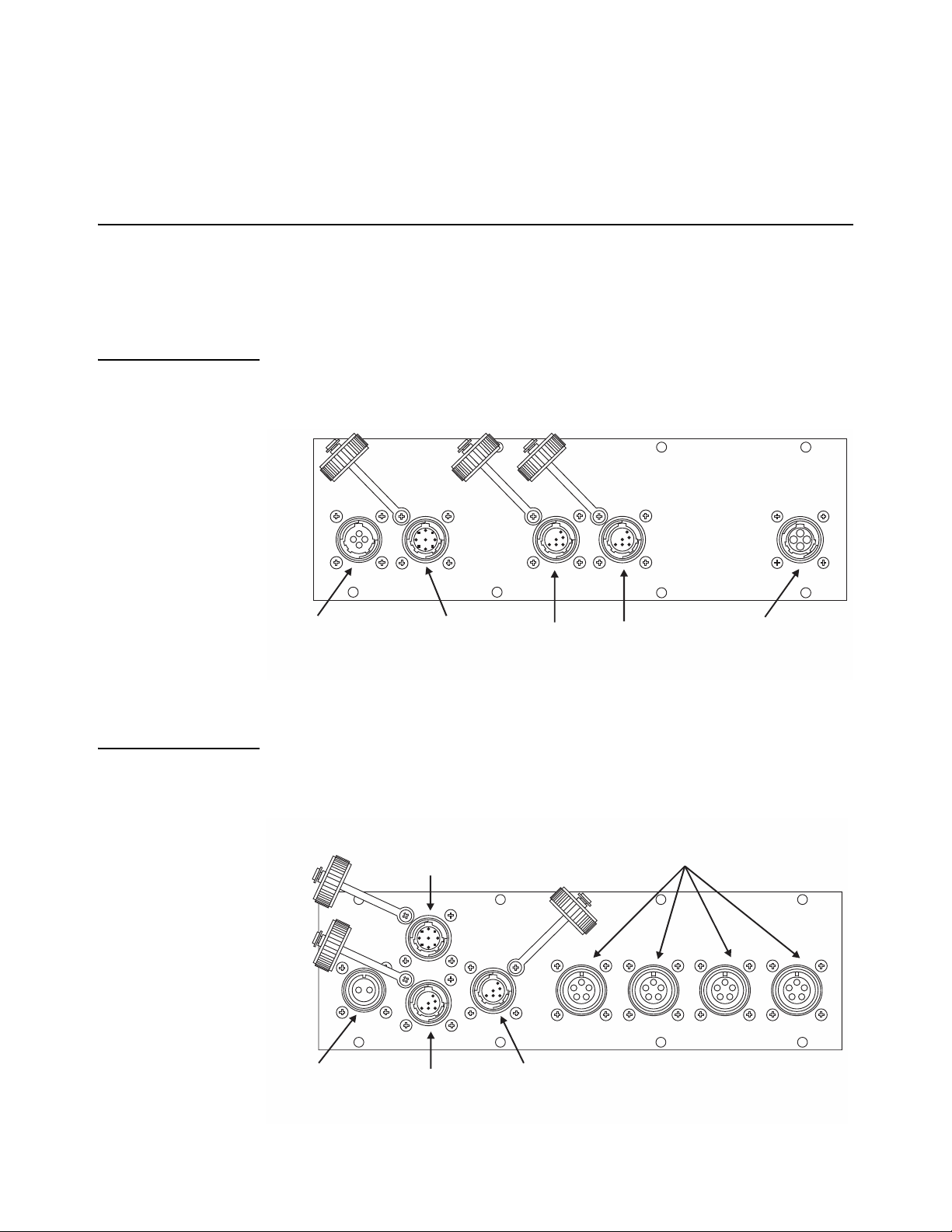
4-pin Power Input
I/O Connector
4-pin AMP J-box
Interface
Com-2
Default
Printer
Com-1
Default
Remote
Display
Com-2
Default
Printer
Com-1
Default
Remote
Display
2-pin Power Input
I/O Connector
4 Weigh Bars
Full Bridge
W/O J-box
recommend to bolt the Ram mount onto the Bracket so the V part of the
bracket will point towards the 2060 (reverse of how the bracket would be
mounted to use as a V mount).
3.2 Cable Connections and Power Requirements
Voltage to the Model 2060 must be 10-36 volts DC, negative ground only. Dropping
below eight volts will cause the Model 2060 to automatically shut itself off, protecting
the battery from being completely draine d.
3.2.1 AWT05-509201 4+ Pin Amp Bottom Plate
This model has 4-pin power , Input/Output, printer, remote display and J-box home run
cable connector.
3.2.2 AWT05-509202 4x 5Pin AWT Bottom Plate
This model has 2-pin power, Input/Output, printer, remote display and input for 4
different weigh bars or J-box home run cable connector.
18 Model 2060 User Instructions
Page 19
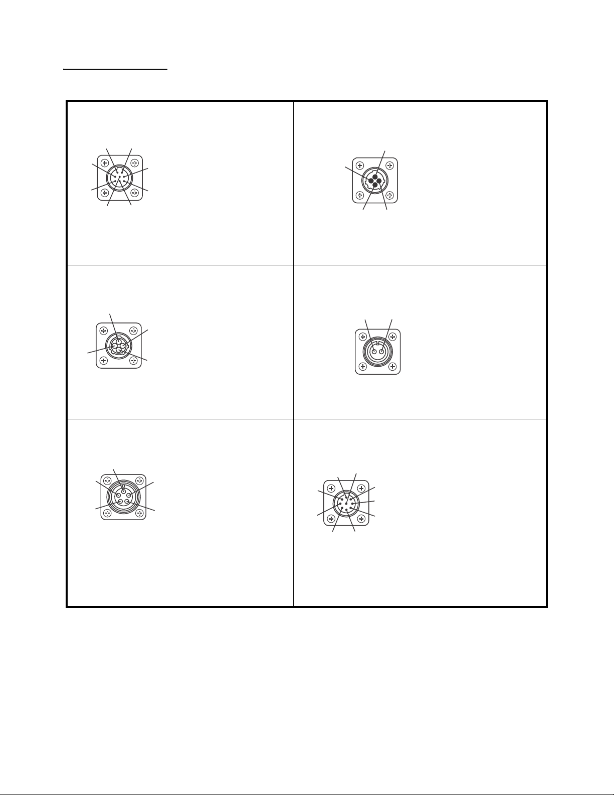
3.2.3 Connectors
RS-232 Port
Pin Description
1N/C
2XMT
3N/C
4RXD
5GND
6GND
7+5V
8+10-36V
Outside View
(Male)
1
2
3
6
4
7
8
5
4-Pin Power Input
Pin Description
1 +12V Input
2GND
3N/C
4N/C
Outside View
(Male)
1
2
3
4
1
2
4
3
4-Pin Amp J-Box Interface
Pin Description
1+ Excitation
2- Bridge
3+ Bridge
4-Excitation
Outside View
(Female)
1
2
3
4
2-Pin Power Input
Pin Description
A+12V
BGND
Outside View
(Female)
AB
5-Pin Weigh Bar Input
Pin Description
A - Bridge
B + Excitation
C+ Bridge
D - Excitation
EShield
Outside View
(Female)
A
E
D
C
B
I/O Connector (9 pin)
Pin Description
1+12V
2+5V
3GND
4 Input 2 (ZERO)
5 Input 3 (RESET target)
6GND
7 Output 1
8 Output 2 (N.O)
9 Input 1 (TARE)
Outside View
(Male)
1
2
3
4
5
6
7
9
8
Model 2060 User Instructions 19
Page 20
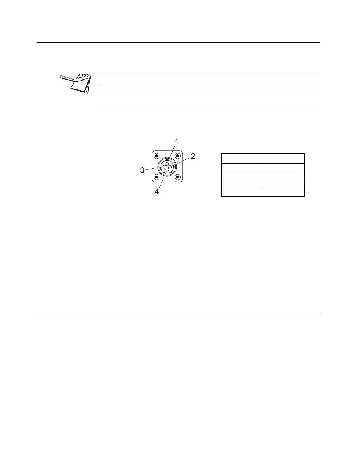
3.3 Routing the Scale Interface Cable
Scale Connector
Pin Description
1 + Excitation
2 - Bridge
3+ Bridge
4 - Excitation
The scale interface cable is the cable that runs from the junction box (j-box) to the
indicator.
For the AWT05-509201 Single Amp you will need to use a J-box.
For the AWT05-509202 4 by 5-pin AWT you will only need to use a j-box for systems
with 5 or more weigh bars.
1. Loosely connect the scale interface cable to the SCALE connector on the
indicator.
Figure 3.1 Scale Connector
2. Run the cable from the indicator to the junction box, allowing some slack in the
cable.
3. Connect the other end of the scale interface cable to the junction box.
4. Inspect the cable run and make sure that the cable is not pinched, kinked or in
the way of moving parts or sharp objects.
5. Be sure to allow some slack when zip tyeing or tucking away the cable.
6. Tighten the connector at the indicator.
3.4 Connecting to a Convenience Outlet
If the equipment you are using has an Auxiliary Power Outlet Strip it is preferred to
supply power to the indicator from the outlet strip rather than the battery.
Most power strip outlets have sp ades that provide constant power (unswitched power)
or key-switched power. Decide which one works best for your application and identify
which spades provide this power type.
If you have a tinned lead power supply and want to connect to the auxiliary power you
need to add a spade to each wire.
l Connect the white wire to the key-switched or unswitched power spade.
l Connect the black wire to the ground spade.
20 Model 2060 User Instructions
Page 21

3.5 Power Connections - Battery
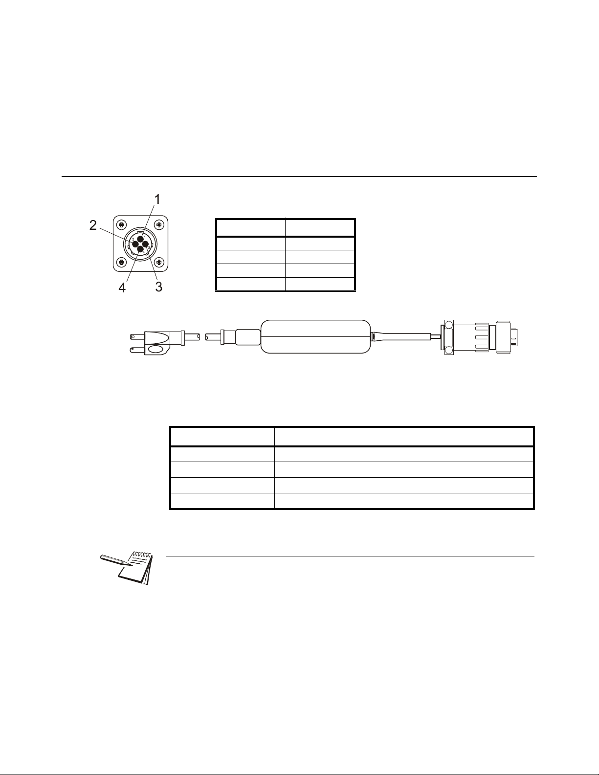
Power Connector
Pin Description
1 +12 VDC
2 Ground
3N/C
4N/C
Available Power Cables
Part Number Description
50474-0036 15 ft / 4.6 m power c ord, Amp
with tinned leads
50474-0051 25 ft / 7.6 m power c ord, Amp
with tinned leads
To indicator
To power
Figure 3.2 Power Connector and Battery Cable
NOTE: Although the above recommends a +12V connection the 2060 specification
allows it to be connected to a +36V power system.
CAUTION!
This indicator can only be connected to positive power terminal with negative
terminal ground battery system.
NOTE: The +ve supply is fused inside of the indicator. Ground battery connection
means that one terminal of the battery is connected to the equipment metal chassis.
The current returns to the battery through the metal work of the equipment ch assis.
1. Disconnect the negative wire from the battery terminal before performing an y
electrical work.
2. Loosely attach the connector end of the power cable to the 2060 indicator.
Model 2060 User Instructions 21
3. Route the cable to the desired power source connection point. If possible, run
the power cable through existing holes and channels so that it will be out of the
way and cannot be damaged by any moving parts. Be sure to keep the cable
from running near a distributor cap, the spark plugs or wires, or the alternator
on the motor. Keep the cable around the periphery of the engine compartment
whenever possible.
Page 22
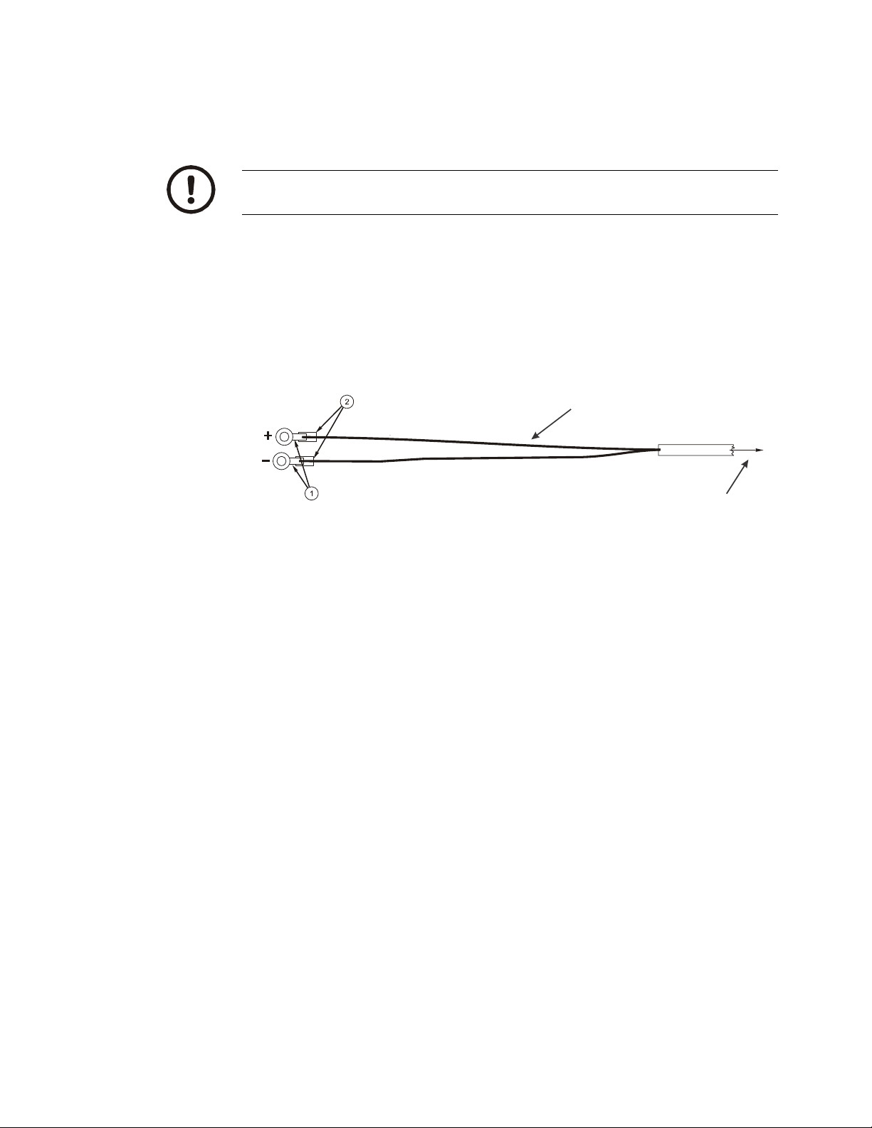
4. Pull through all the slack in the cable and cable tie the power cable in
To battery
connection
White Wire
Power Cable
to Indicator
appropriate places to hold it in place.
5. Disconnect the power connector from the back of the indicator.
CAUTION: Non-approved power connections may damage equipment and void
warranty.
5a. Crimp the ring terminals (item 1) onto the wires as shown in Figure 3.3 below.
5b. Using a heat gun, shrink all of the heat shrink tubing (item 2) in place.
If the battery terminals have bolts to which you can connect the ring
terminals, do so. The white wire should be attached to the positive (+)
terminal. The black wire should be attached to the negative (-) terminal.
Skip to step 9
Figure 3.3 Power Cable Wiring
6. Connect the white power cable as close as possible to the battery's positive
voltage terminal without attaching it directly to the battery terminal. In other
words, the first place the positive terminal is connected to is where you should
tap in with the white power cable for the instrument.
7. Connect the black ground cable as close as possible to the battery's negative
terminal without attaching it directly to the battery. In other words, the first
place the negative terminal is connected to is where you should tap in with the
black ground cable for the instrument. The chassis may not provide the proper
ground potential. Check with the equipment manufacturer to de termine if
battery ground is isolated from chassis ground.
8. Tighten the AMP or AWT connector on the underside of the indicator. See
figure 3.2.
9. Reconnect battery power.
10. Press and hold the On/Off key on the 2060 until the red light above the key
comes on.
11. Check that the instrument powers on.
22 Model 2060 User Instructions
Page 23
3.6 Wiring 2060 Indicator to Equipment Power Systems
In all cases it is advised that you consult the equipment manufacturer or authorized
agents for advice before installing a weighing system. These are configurations that
you may find on different equipment manufacturers models.
Note that the electrical connection to the metal wor k of the equipment is
shown by the following symbol:
ENSURE THAT YOU DO NOT SHORT CIRCUIT THE BATTER Y ;
SPARKS AND ARCING FROM A BATTERY SHORT CIRCUIT CAN
CAUSE SEVERE BURNS.
? Always connect to the supply battery terminal last.
? Complete the wiring to the weighing indicator before connecting to the
indicator. Check with a resistance meter to insure there is no connection
between the supply wire and chassis ground.
? Verify battery system you are connecting to has negative ground.
? When you are satisfied with the above connect to the battery supply.
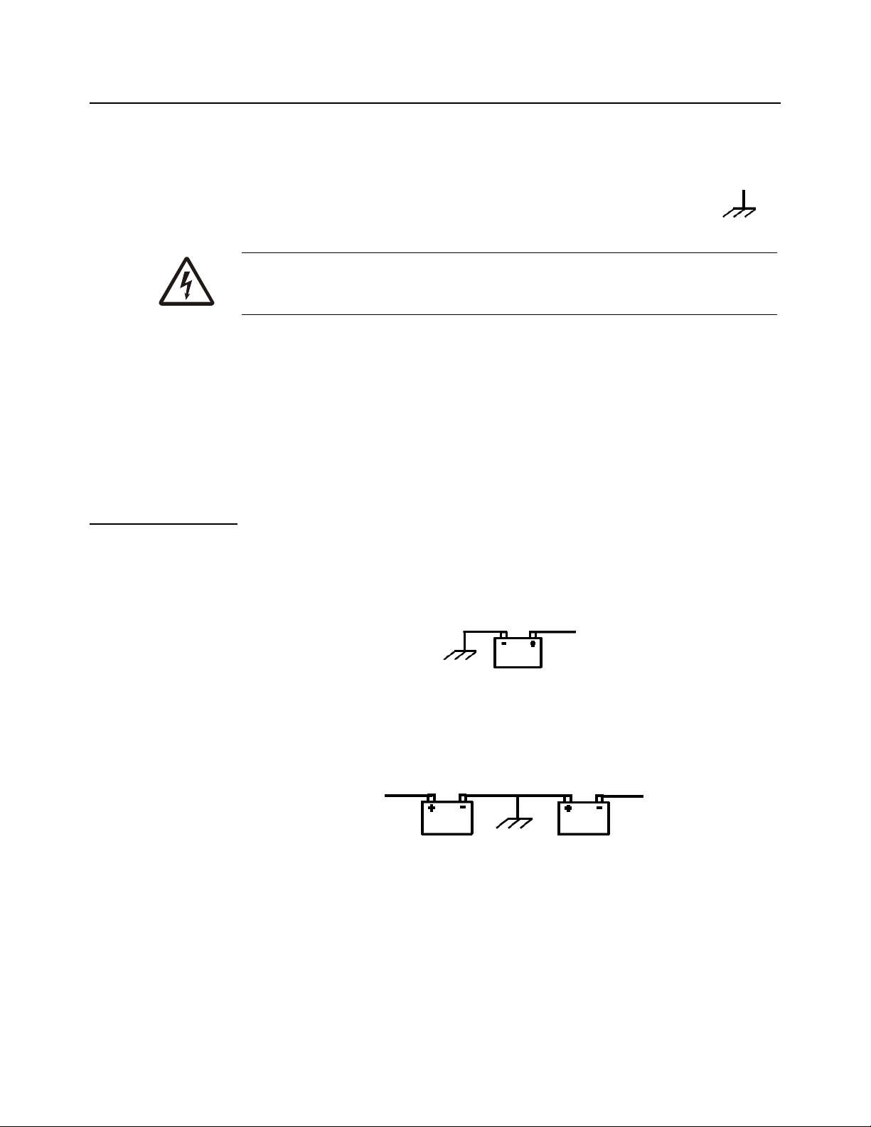
3.6.1 12 Volt Power Systems (one and two 12 V batteries)
Single Battery
12 V Battery negative terminal ground connection +12V power supply. DO NOT
REVERSE THE POLARITY!
Figure 3.4 Single Battery Connection
Two 12 Volt Batteries Wired in Series
Center ground connection +12V power supply
Figure 3.5 Two 12 Volt Battery Connection
Model 2060 User Instructions 23
Page 24

3.6.2 24 Volt Power Systems
The negative terminal connection of the first battery connected to ground, +ve
connection wired to the negative terminal of the second battery, the +ve is the +24V
power supply. DO NOT REVERSE THE POLORITY!
3.6.3 Grounded Power Systems
Ground battery connection means that one terminal of the battery is connected to the
equipment metal chassis. The current returns to th e battery throu gh the met al work of
the equipment chassis.
If the power system used is not connected to the chassis ground and is electrically
isolated from other equipment then this should not cause any problems with weighing
indicators. Normally the indicator is connected to the equipment power supply using
one of the grounded power systems described above.
Problems Using Chassis Ground
Figure 3.6 24 Volt Battery Connection
If the mating parts of the chassis are corroded then the resistance can be high which
depending on the current flow may reduce the voltage available to drive accessories.
There may be high power devices such as light s or motors which when switched on or
off because they share the current path could cause the voltage available to drive
accessories to be electrically noisy . In the case of motors then the y can cause very high
voltage spikes which could damage accessories.
Grounding Weight Indicators
For weighing indicators it is advised that the one of the power supply inputs is
connected to the equipment ground battery terminal through a sep arate insulated wire.
The separate return wire reduces the risk of chassis corrosion problems and over
voltage caused by other equipment electrical systems.
The ground connection ensures that the current flow in the indicator power wires is
always in the same direction, so that the built in circuit protection is effective.
If the system described in section 3.6.2 is used then there is available a 12V power
connection between 12V and 24 V. If this is used as a 12V power supply connection
the following problems could occur;
? On some indicators the metal housing of the indicator is connected to on e of
the power connections the 12V from the grou n d conn ec t ion. If th er e is an
accidental connection from the indicator housing to the equipment metal
work then there will be a large fault current which will cause the power cable
0V wire to heat up.
24 Model 2060 User Instructions
Page 25
? The internal power surge protection in the indicator which protects it, the
Power Connector
Pin Description
1 + 12 VDC
2 Ground
3 Output #1
4 Input #1
weigh bars and other components such as external displays will not be
effective against over voltages with resp ect to the ground. This could lead to
damage of the weigh bars which are connected by their load connections to
the ground although internally electrically isolated. Other accessories such
as the external displays, which have metal housings, may also be damaged
if there is a high voltage between the power supply and housing.
3.7 Power Connections - AC
Figure 3.7 AC Power Connections
Table 3.1 AC to DC Cables
Part Number Description
AWT15-501422 China AC to DC power converter 12VDC 5A Amp
AWT15-501275 EU AC to DC power converter 12VDC 5A Amp
AWT15-501273 NA AC to DC power converter 12VDC 5A Amp (Replaces 28300-0057)
AWT15-501274 UK AC to DC power converter 12VDC 5A Amp
Refer to the Ag power supply price sheet for more details on available cables and
drawings.
For applications requiring AC power, follow these instructions.
1. Loosely attach the AC power adapter to the area near the outlet with a cab le tie.
2. Route the cable from the electrical outlet to the indicator. If possible, run the
power cable through existing channels or conduit so that it will be out of the
way and cannot be damaged by any moving parts.
3. Inspect the cable run and make sure that the cable is not pinched, kinked or in
the way of moving parts or sharp objects.
Model 2060 User Instructions 25
Page 26
4. Tuck or cable tie the excess cable along the run as necessary.
COM Port
Pin Description
1N/C
2XMT
3N/C
4RXD
5GND
6GND
7+5 V
8+8 V
5. Tighten the AMP connector on the underside of the indicator.
6. Plug the AC adapter in to the outlet.
7. Press and hold the On/Off key on the 2060 until the red light above the key
comes on.
8. Check that the indicator powers on.
3.8 Optional Communications Connections
The 2060 comes with two standard an d a third optiona l serial commu nications (C OM)
ports which can be used for various peripheral equip ment such as a the XLR Series
remote displays, printer,RM200 or other device. Use the following instructions for
connecting a serial peripheral device to the 2060.
All COM ports on the 2060 indicator have the same pinouts as shown in Figure 4.11.
COM 1 is configured for XLR Series Remote Displays, COM 2 is configured for
Printer COM 3 Selectable default settings for each port are: Baud: 9600, Data Bits:8,
Parity: None, Stop Bits:1, C-trol: None.
Contact your Avery Weigh-Tronix representative if you need to change these settings.
1. Disconnect the indicator and peripheral device from the power source.
2. Loosely connect the communications cable (serial cable) to the required COM
port.
Figure 3.8 Sample COM Port
3. Route the serial cable to the peripheral device using existing channels or
conduit whenever possible.
4. Connect the serial cable to the device.
5. Inspect the cable run and make sure that the cable is not pinched, kinked or in
the way of moving parts or sharp objects.
6. Tighten the connector at the indicator.
26 Model 2060 User Instructions
Page 27

7. Reconnect power to the indicator and device.
8. Press and hold the On/Off button on the 2060 until the red light comes on and
the indicator powers on.
3.8.1 Additional Connectors
The 2060 also has the following connectors:
? USB connector - located on the right side of the enclosure. Use the USB
connector to connect a USB keyboard or flash drive.
? Ethernet connector - Standard internal with optional port on bottom plate.
This port is application dependent
Your scale is now installed and ready for use. If you have any questions during
installation, please contact your local Avery Weigh-Tronix representative.
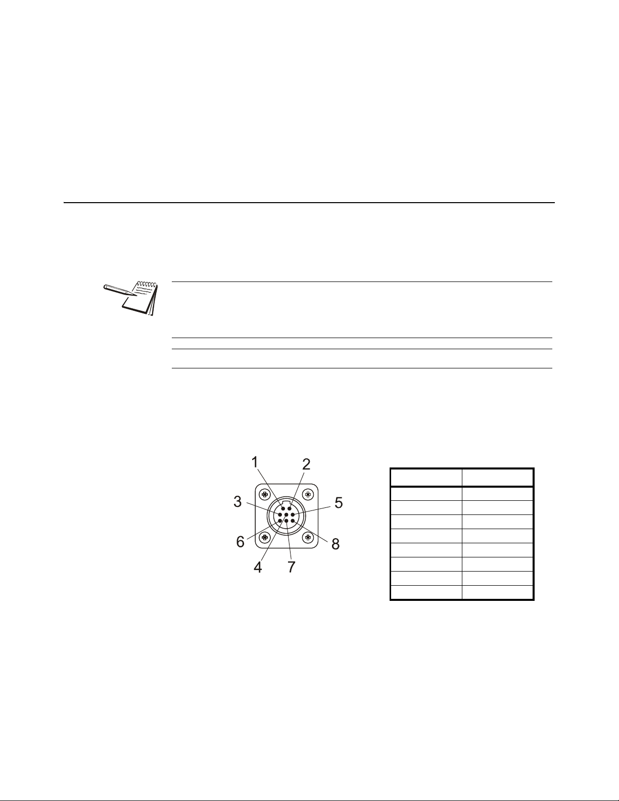
3.8.2 I/O Connector Pins (9 pin connector)
Connector / Pin Description Wire Color
P12-1 +12V BLK
P12-2 +5V BRN
P12-3 GND RED
P12-4 Input 2
(ZERO)
P12-5 Input 3
(RESET Target)
P12-6 GND GRN
P12-7 Output-1
(GND signal output once Alarm light is engaged)
P12-8 Output-2
(currently not used)
P12-9 Input 1
(TARE)
ORN
YEL
BLUE
GRAY
VIOLET
Example: External wiring to RESET Target weight:
To activate and RESET Target amount, connect the yellow and RED wire.
Example: External Wiring to turn off Target (auger/Conveyor):
Connect to the Blue Wire (Gnd Output) and BLACK (+12V) to turn on 12 volt relay
Model 2060 User Instructions 27
Page 28

4 Quick Start Calibration Guide
This Quick Start Guide includes calibration details for AWTX Weigh Bars standard
configuration or Custom configuration, and custom configuration for other brands of
Weigh Bars.
4.1 Calibrate the 2060 with a Standard Configuration Number
This section covers the standard calibration process for the scale system using precalibrated Avery Weigh-Tronix weigh cells. If using other brands of weigh cells or
configurations of AWTX weigh cells not mentioned below you will need to use Custom
Configuration. Refer to section 4.2 for an example of Custom Configuration and
Custom Configuration table.
4.1.1 Determine the Configuration Number
This section shows you how to find and enter a configuration number that sets up the
indicator for the following: type of Weigh Bar calibrati on diameter, capacity, increment,
and units.
The following are instructions for determining what number needs to be entered into
the calibration configuration number menu. The calibration diameter ( size) establishes
the first two numbers for the configuration code. These nu mbers are on the top center
of the label below the heading calibration diameter. In this example the calibration
diameter will be 2 1/8.
Figure 4.1 Sample Weigh Bar Label
Example:
All standard configuration numbers consist of five digits. Follow the example below.
1st & 2nd digit = Calibration Diameter
3rd Digit= Capacity and increment (Division) size. Note that capacity
refers to the max weight the scale will display not the actual capacity of
the equipment that scale system is installed on.
4th Digit= 0 (Print format will always be 0 for 2060)
5th Digit= Selection of Pounds (0) or Kilograms (4)
Model 2060 User Instructions 28
Page 29

2 1/8 calibration diameter , 20,000 (capacity limit) x 5 (increments the scale counts
03
1-7/8 20K x 1 20K x 2 20K x 5
200K x 10
200K x 20
200K x 50
04
2 20K x 1 20K x 2 20K x 5
200K x 10
200K x 20
200K x 50
05
2-1/8 20K x 1 20K x 2 20K x 5
200K x 10
200K x 20
200K x 50
06
2-1/4 20K x 1 20K x 2 20K x 5
200K x 10
200K x 20
200K x 50
1st & 2nd
Digits
CALIBRATION SIZE
CAPACITY X INCREMENT SIZE
3rd DIGIT 0 1 23
4
5
in), Print format is always 0, unit = lb.
Configuration code = 05204
1. The first two digits are the calibration size. In our example the calibration size is
2 1/8. The corresponding number is found in Table 4.1 on page 30. Find the
desired calibration size. In this example, 05 are the first two digits.
Figure 4.2 1st and 2nd Digit (Calibration Size)
2. The third digit is the capacity and increment (division) size within the
calibration size. In this example 20,000 x 5 is being used. The corresponding
number is also found in T able 4.1. Follow the row of the chosen calibration size
(i.e. 05) until you find the desired capacity and increment size. Follow the
column down to the bottom row. The third digit is located on the bottom row.
For this example, 2 is the number.
Model 2060 User Instructions 29
Figure 4.3 3rd Digit (Capacity and Increment Size)
3. The fourth digit is for print formats. The 2060 print formats are determined by
the application so the 4th digit will always be 0.
4. The 5th digit solely selects lb or kg in this example we want kg so the 5th digit
becomes 4. Auto-loc, or Auto-acc is determined by the application software.
Page 30

4.1.2 Configuration Codes
The following tables show how to establish a Configuration Code Number (CCN) to
configure the 2060 indicator . Table 4.1 applies to all 3 Weigh Bar junction box systems
and 4 Weigh Bar junction box systems.
? The only exception is the Calibration Size 2 1/4D-P, which can be used with
8 Weigh Bars that are 2 1/4 D cal size.
? If you use any other number of Weigh Bars, use custom settings 97, 98, or
99 and refer to section 4.2 to find your configuration numbers based on
reading of .4mV/V.
T able 4.1 1st/2nd (Weigh Bar Size) and 3rd CCN Digit s (Capacity and Increment)
1st and
2nd
CALIBRATION SIZE
CAPACITY x INCREMENT SIZE
Digit
00 5/8 200 x 0.01 200 x 0.02 200 x 0.05 2K x 0.1 2K x 0.2 2K x 0.5
01 1 2K x 0.1 2K x 0.2 2K x 0.5 20K x 1 20K x 2 20K x 5
02 1-1/4 2K x 0.1 2K x 0.2 2K x 0.5 20K x 1 20K x 2 20K x 5
03 1-7/8 20K x 1 20K x 2 20K x 5 200K x 10 200K x 20 200K x 50
04 2 20K x 1 20K x 2 20K x 5 200K x 10 200K x 20 200K x 50
05 2-1/8 20K x 1 20K x 2 20K x 5 200K x 10 200K x 20 200K x 50
06 2-1/4 20K x 1 20K x 2 20K x 5 200K x 10 200K x 20 200K x 50
07 2-1/4D 20K x 1 20K x 2 20K x 5 200K x 10 200K x 20 200K x 50
08 2-1/4D-P 200K x 10 200K x 20 200K x 50 200K x 100 200K x 200 200K x 500
09 2-1/2 20K x 1 20K x 2 20K x 5 200K x 10 200K x 20 200K x 50
10 3-1/8 200K x 10 200K x 20 200K x 50 200K x 100 200K x 200 200K x 500
11 4 200K x 10 200K x 20 200K x 50 200K x 100 200K x 200 200K x 500
12 CC20/CC30 20K x 1 20K x 2 20K x 5 200K x 10 200K x 20 200K x 50
13 Alley Weigh 2K x 0.1 2K x 0.2 2K x 0.5 20K x 1 20K x 2 20K x 5
14 CC30-3 20K x 1 20K x 2 20K x 5 200K x 10 200K x 20 200K x 50
15 Chute Weigh 20K x 1 20K x 2 20K x 5 200K x 10 200K x 20 200K x 50
16 CC-50 200K x 10 200K x 20 200K x 50 200K x 100 200K x 200 200K x 500
18 SPARE 20K x 1 20K x 2 20K x 5 200K x 10 200K x 20 200K x 50
20 1-digi 2K x 0.1 2K x 0.2 2K x 0.5 20K x 1 20K x 2 20K x 5
21 1 P OLY(DIGI) 20K x 1 20K x 2 20K x 5 200K x 10 200K x 20 200K x 50
22 1-7/8,2(DIGI) 20K x 1 20K x 2 20K x 5 200K x 10 200K x 20 200K x 50
23 2-1/8,2-1/2,2-7/8,3-3/4
20K x 1 20K x 2 20K x 5 200K x 10 200K x 20 200K x 50
(DIGI)
97 Custom Setting 200 x 0.01 200 x 0.02 200 x 0.05 2K x 0.1 2K x 0.2 2K x 0.5
98 Custom Setting 20K x 1 20K x 2 20K x 5 200K x 10 200K x 20 200K x 50
99 Custom Setting 200K x 100 200K x 200 200K x 500 - - -
3rd DIGIT 0 1 2 3 4 5
30 Model 2060 User Instructions
Page 31

The fourth digit is for print formats. The 2060 print formats are determined by the
HOME
application so the 4th digit will always be 0.
Table 4.2 4th CCN Digit (Print Format)
4th
Digit
Print Formats
0
The 5th digit selects the calibration unit; lb (0) or kg (4).
Table 4.3 5th CCN Digit (Calibration Unit)
5th
Digit
Units
0 lb
4 kg
4.1.3 Enter the Configuration Code Number Parameter (Cfg Num)
1. From the home screen, press and hold the key for three beeps (3
seconds), then release. The password screen will be displayed.
2. Enter the password 3088 within 5 seconds and press the F3/ . Busy will be
displayed briefly and the calibration menu will be accessed.
3. The Calib menu will be highlighted.
? If you have Avery Weigh-Tronix Ag Weigh Cells you can chose between
standard and custom calibration codes to calibrate your system.
? If you are using weighs from a different manufacturer you will want to go to
section 4.2 for custom calibration.
4. Press F3/ . Scale 1 will be highlighted.
5. Press F3/ . The calibration choices will be displayed.
6. From Scale 1 Calib screen, use the F1/ or F2/ to highlight Cfg Num.
7. Press the F3/ key.
8. Enter the calibration number and press the F3/ key. The Scale 1 Calib
screen will be displayed.
9. To save and exit, press the BACK key until SAVE SETTINGS screen is
displayed. SAVE no will be the first choice displayed.
Model 2060 User Instructions 31
Page 32

10. Press the F2/ key to scroll to SaveYes. Press the F3/ key to accept and
save the configuration number. Busy will be displayed.The number will be
saved and the display will return to the home screen.
If attempting to enter an invalid number display will show CAN’t and return to
CONFIG.
4.1.4 Configuration Code Numbers for Common Applications:
SEED TENDERS & TMR MIXERS:
2 1/8 inch calibration weigh bar 20,000 x 5 lb (05200)
2 ½ inch calibration weigh bar 200,000 x 10 (09300)
2 1/4D calibration weigh bar 200,000 x 10 lb (07300)
CC-30 Compression Cell 200,000 x 10 lb (14300)
GRAIN CARTS:
2 1/4D calibration weigh bar 200,000 x 20 lb (07400)
CC-30 Compression Cell 200,000 x 20 lb (14400)
If it is impossible to know exactly which weigh bars are on the scale system, try one of
the recommended Configuration Code Numbers and keep entering the recommended
code numbers until the scale appears to be weighing properly . (See section 4.2.4: Enter
Configuration Code Number (Cfg Num).
After several attempts at a code number, if the scale still does not weigh properly
please consider the following:
? Contact your dealer or distributor where the scale was purchased.
? Access the Avery Weigh-Tronix website at www.agscales.com for more
debugging tips.
? Contact the Avery W eigh-Tronix service department at 1-800-458-7062 for
assistance.
32 Model 2060 User Instructions
Page 33

4.2 Custom Configuration Number for AWTX W eigh Bars
97
Custom Setting 200 x 0.0 1 200 x0.0 2 200 x 0.05 2K x 0.1 2K x 0.2 2K x 0.5
98
Custom Setting 20K x 1 20K x 2 20K x 5 200K x 10
200K x 20
200K x 50
99
Custom Setting 200K x 1 200K x 2 200K x 5
---
1st & 2nd
Digits
CALIBRATION SIZE
CAPACITY X INCREMENT SIZE
3rd DIGIT 0 1 23
4
5
97
Custom Setting 200 x 0.0 1 200 x0.0 2 200 x 0.05 2K x 0.1 2K x 0.2 2K x 0.5
98
Custom Setting 20K x 1 20K x 2 20K x 5 200K x 10
200K x 20
200K x 50
99
Custom Setting 200K x 1 200K x 2 200K x 5
---
1st & 2nd
Digits
CALIBRATION SIZE
CAPACITY X INCREMENT SIZE
3rd DIGIT 0 1 23
4
5
For use with all AWTX Ag Weigh Bars. Two numbers (Configuration Code and Custom
Configuration) must be entered into the 2060. Refer to Enter Configuration Code
Number (Cfg Num) on page 38.
? Configuration Code Number (Cfg Num)
? Custom Calibration Number (Cust.Cfg)
4.2.1 Determine Configuration Number
The following are instructions for how to determine what number needs to be entered
into the calibration configuration number menu. This selection appears as Cfg Num.
Example:
6 2 1/2 calibration weigh bars, 200,000 (capacity limit) x 20 (increments the scale
counts in), print format 0, kg configuration code = 98404
1. In our example the weigh bars are 2 ½ calibration. Figure 4.4:1st and 2nd Digit
(Custom Setting) is an excerpt from Table 4.1 on page 30. In this example, 98
are the first two digits.
Figure 4.4 1st and 2nd Digit (Custom Setting)
2. The third digit is the Capacity and Increment Size within the custom setting. In
this example 200,000 x 20 is being used. Figure 4.5:3rd Digit (Capacity and
Increment Size) is an excerpt from Table 4.1. Follow the column down to the
bottom row. The third digit is located on the bottom row. For this example, 4 is
the number.
Figure 4.5 3rd Digit (Capacity and Increment Size)
3. The fourth digit is for print formats. The 2060 print formats are determined by
the application so the 4th digit will always be 0.
4. The 5th digit selects the calibration unit; lb (0) or kg (4).
Model 2060 User Instructions 33
Page 34

4.2.2 Determine Custom Calibration Number
2 1/2
5
32133
2 1/2
6
38559
2 1/2
7
44986
Cal Size
No. of bars
CUSTOM # (lb/kg)
This number will be entered in the CUSTOM Configuration parameter which appears
as Cust.Cfg in the 2060 menu. In this example we have 6 2 ½ Cal Size weigh bars.
Figure 4.6 is an excerpt from Table 4.4:Custom Number Table.
Example for Custom Configuration:
6 2 1/2 cal size weigh bars, 200,000 x 20 kg = 38559
1. First you go down left hand column (Cal Size) in Table 4.4 and find 2 1/2.
2. Next, in the 2nd column find 6 for 6 weigh bars.
3. The third column 38559 is the custom number.
Figure 4.6 Custom Configuration Number
Refer to section 4.2.4 on page 38. Refer to Table 4.4 on page 34 for Custom Number
codes.
4.2.3 Custom Number Table
Table 4.4 Custom Number Table
Cal Size
Number of
Bars
Custom # (lb)
@.4mV/V
Custom # (kg)
@.4mV/V
5/8 1 92.3 41.8
5/8 2 184.5 83.7
5/8 3 276.8 125.5
5/8 4 369 167.4
5/8 5 461.3 209.2
5/8 6 553.6 251.1
5/8 7 645.8 292.9
5/8 8 738.1 334.8
1 1 375.3 170.2
1 2 750.6 340.5
1 3 1126 510.7
1 4 1501.3 681
1 5 1876.6 851.2
1 6 2251.9 1021.5
1 7 2627.2 1191.7
1 8 3002.6 1361.9
34 Model 2060 User Instructions
Page 35

Cal Size
Number of
Bars
Custom # (lb)
@.4mV/V
Custom # (kg)
@.4mV/V
1 1/4 1 893 405
1 1/4 2 1785.9 810.1
1 1/4 3 2678.9 1215.1
1 1/4 4 3571.9 1620.2
1 1/4 5 4464.9 2025.2
1 1/4 6 5357.8 2430.3
1 1/4 7 6250.8 2835.3
1 1/4 8 7143.8 3240.4
1 7/8 1 2630 1193
1 7/8 2 5261 2386
1 7/8 3 7891 3579
1 7/8 4 10522 4773
1 7/8 5 13152 5966
1 7/8 6 15782 7159
1 7/8 7 18413 8352
1 7/8 8 21043 9545
2 1 3270 1483
2 2 6540 2967
2 3 9810 4450
2 4 13080 5933
2 5 16350 7416
2 6 19620 8900
2 7 22890 10383
2 8 26160 11866
2 1/8 1 3753 1702
2 1/8 2 7506 3405
2 1/8 3 11260 5107
2 1/8 4 15013 6810
2 1/8 5 18766 8512
2 1/8 6 22519 10215
2 1/8 7 26272 11917
2 1/8 8 30026 13619
2 1/4 1 4613 2092
2 1/4 2 9226 4185
2 1/4 3 13839 6277
2 1/4 4 18452 8370
2 1/4 5 23065 10462
2 1/4 6 27678 12554
2 1/4 7 32291 14647
2 1/4 8 36904 16739
Model 2060 User Instructions 35
Page 36

Cal Size
Number of
Bars
Custom # (lb)
@.4mV/V
Custom # (kg)
@.4mV/V
2 1/4Dual 1 9226 4185
2 1/4Dual 2 18452 8370
2 1/4Dual 3 27678 12554
2 1/4Dual 4 36904 16739
2 1/4Dual 5 46130 20924
2 1/4Dual 6 55356 25109
2 1/4Dual 7 64582 29294
2 1/4Dual 8 73808 33479
2 1/2 1 6427 2915
2 1/2 2 12853 5830
2 1/2 3 19280 8745
2 1/2 4 25706 11660
2 1/2 5 32133 14575
2 1/2 6 38559 17490
2 1/2 7 44986 20405
2 1/2 8 51412 23320
3 1/8 1 12955 5876
3 1/8 2 25910 11752
3 1/8 3 38864 17629
3 1/8 4 51819 23505
3 1/8 5 64774 29381
3 1/8 6 77729 35257
3 1/8 7 90684 41133
3 1/8 8 103638 47010
4 1 26523 12031
4 2 53046 24061
4 3 79569 36092
4 4 106092 48122
4 5 132615 60153
4 6 159137 72184
4 7 185660 84214
4 8 212183 96245
Alley Weigh bar 1 389 176
Alley Weigh bar 2 778 353
Alley Weigh bar 3 1167 529
Alley Weigh bar 4 1556 706
Alley Weigh bar 5 1946 882
Alley Weigh bar 6 2335 1059
Alley Weigh bar 7 2724 1235
Alley Weigh bar 8 3113 1412
36 Model 2060 User Instructions
Page 37

Cal Size
Number of
Bars
Custom # (lb)
@.4mV/V
Custom # (kg)
@.4mV/V
Chute Weigh bar 1 2630 1193
Chute Weigh bar 2 5261 2386
Chute Weigh bar 3 7891 3579
Chute Weigh bar 4 10522 4773
Chute Weigh bar 5 13152 5966
Chute Weigh bar 6 15782 7159
Chute Weigh bar 7 18413 8352
Chute Weigh bar 8 21043 9545
CC-20/CC-30 1 5634 2555
CC-20/CC-30 2 11268 5111
CC-20/CC-30 3 16901 7666
CC-20/CC-30 4 22535 10222
CC-20/CC-30 5 28169 12777
CC-20/CC-30 6 33803 15333
CC-20/CC-30 7 39437 17888
CC-20/CC-30 8 45070 20444
CC-30-3 1 4000 1814
CC-30-3 2 8000 3629
CC-30-3 3 12000 5443
CC-30-3 4 16000 7257
CC-30-3 5 20000 9072
CC-30-3 6 24000 10886
CC-30-3 7 28000 12701
CC-30-3 8 32000 14515
CC-50 1 8000 3629
CC-50 2 16000 7257
CC-50 3 24000 10886
CC-50 4 32000 14515
CC-50 5 40000 18144
CC-50 6 48000 21772
CC-50 7 56000 25401
CC-50 8 64000 29030
Model 2060 User Instructions 37
Page 38

4.2.4 Enter Configuration Code Number (Cfg Num)
1. From the home screen press and hold the HOME key for three beeps (3
seconds), then release. The password screen will be displayed.
2. Enter the password 3088 within 5 seconds and press the F3/ . Busy will be
displayed briefly and the calibration menu will be accessed.
3. The Calib menu will be highlighted. Press the F3/ .key.
? If you have Avery Weigh-Tronix Ag Weigh Cells you can chose between
standard and custom calibration codes to calibrate your system.
? If you are using weighs from a different manufacturer you will want to go to
section 4.2 for custom calibration.
4. From Scale 1 Calib screen press the F3/ .key.
5. Use the F1/ or F2/ to highlight Cfg Num.
6. Press the F3/ key.
7. Enter the calibration number and press the F3/ .key. The Scale 1 Calib
screen will be displayed.
8. If you are using standard configuration codes proceed to step 8a if you are
using a custom code proceed to step 8b.
8a. To save and exit, pr ess the BACK key. The SAVE SETTINGS screen will be
displayed. SAVE no will be the first choice displayed.
8b. If you used a Custom Configuration Number that starts with 97, 98, 99,
press F2/ to highlight Cust. Cfg (Custom Configuration) and press F3/
8c. Enter the custom number a nd press F3 / .
9. Use the F1/ or F2/ key to scroll to SaveYes. Press the F3/ key to
accept and save the configuration number.The number will be saved and the
display will return to the home screen.
4.2.5 Enter Custom Configuration Number (Cust.Cfg)
This parameter will only be visible if a custom configuration number has been entered
previously (starts with 97, 98, 99).
1. From the home screen press and hold the HOME key for three beeps (3
seconds), then release. The password screen will be displayed.
2. Enter the password 3088 within 5 seconds and press the F3/ . Busy will be
displayed briefly and the calibration menu will be accessed.
3. The Calib menu will be highlighted.
? If you have Avery Weigh-Tronix Ag Weigh Cells you can chose between
standard and custom calibration codes to calibrate your system.
? If you are using weighs from a different manufacturer you will want to go to
section 4.2 for custom calibration.
4. From Scale 1 Calib screen, use the F1/ or F2/ to highlight Cust.Cfg.
38 Model 2060 User Instructions
Page 39

5. Press the F3/ key.
6. Enter the calibration number and press the F3/ key. The Scale 1 Calib
screen will be displayed.
7. To save and exit, press the BACK key. The SAVE SETTINGS screen will be
displayed. SAVE no will be the first choice displayed.
8. Use the F1/ or F2/ key to scroll to SaveYes. Press the F3/ key to
accept and save the configuration number.The number will be saved and the
display will return to the home screen.
4.2.6 Custom Configuration Number Calibration
When using Custom Configuration you must use test weights or verify a load on
another scale. Refer to section 4.2.4 on page 38 for instructions on entering the custom
number into the calibration menu.
Example:
Grain Cart Scale Shows net weight of 52,500 lbs loaded onto Truck Calibrated Truck
Scale shows net weight of 53,800 lbs Current Custom Configuration number 38559
Step 1: Calculate difference in weight between Grain Cart Scale and
Truck Scale: 52,800-53,800=1,300 lbs
Step 2: Divide difference by Grain Cart Weight to figure % (1,300/
52,500=.025 or 2%)
Step 3: In this case the Grain Cart weight was to low so we need to raise
the custom number by 2% (38559x1.02=39,330.18) We round this to
39,330 and enter this in place of the old custom number 38559
If we where 2% to high we simply would lower the custom number by 2%
(38,559x.98=37,787.82)
Step 4: Verify if the next load is within 1% of the Calibrated Truck scale.
If it is not within 1% you can repeat the process above.
Model 2060 User Instructions 39
Page 40

4.3 Configuring the 2060 for Other Brand Weigh Bars and Loadcells
The 2060 will work with any brand of strain gage based weigh bar or load cell. Once
the system is installed, the 2060 will then need to be calibrated using the Configuration
Code Number (Cfg Num) and (Cust.Cfg).
4.3.1 Custom Calibration Number
The Custom Configuration can be accomplished by either of the methods below
? Use the mv/V information from the weigh bars (Example 1 below)
? Placing Known Weight on Scale (Example 2 below)
Example 1:
Need to calibrate to 4 weigh bars with the following information:
1 weigh bar 2.0 mv/V = 5,000 lb
Therefore 4 weigh bars would be 2.0 mv/V = 20,000 lb for the system.
5000lb (weigh bar capacity) x 4 (number of weigh bars) = 20,000
Next is to figure out the custom number per 0.4 mv/V
2.0 mv/V (mv/V of weigh bar) / 0.4 mv/V (custom number mv/V) = 5 mv/V
20,000 (total capacity of weigh bars) / 5 (mv/V answer from above) = 4000
The custom number would be the weight value at 0.4 mv/v or as in th is examp le 4000
lb.
OR
The other method is to first enter in the Configuration Code Number (refer to section
4.2.1 for details on how to determine the Configuration Code Number) and then place
a known weight on the scale. Record that weight and then figure the scale factor
difference from the known weight and the displayed weight. Then this factor needs to
be multiplied by the current Custom Number to calculate the new Custom Number.
Example 2:
Current Custom configuration Code = 4000
Known Weight Applied 15,000
2060 Displayed Weight 10,000
15,000 (Known Weight Applied) / 10,000 (2060 Displayed Weight) = 1.5
(Current CUSTOM #) x (Calibration Factor) = (New CUSTOM #)
4000 x 1.5 = 6000
Therefore go to the Custom Calibration setting in the SETUP menu and change as
needed. Refer to section 4.2.4 on page 38 for instructions on entering the values.
40 Model 2060 User Instructions
Page 41

Model 2060 User Instructions 41
Page 42

5 Menus
5.1 Accessing the menus
To access a me n u, press an d ho ld the HOME key and the password entry screen is
displayed:
Type in the password for the menu you want and press the Enter (F3) key.
Password Menu Level Accessed Menus
111 User User, About, Audit
3570 Diagnostics Diag, User, About, Audit
1793 Application Application specific items.
3088 Admin Setup, Diag, User, About, Audit
The password must be entered within approximately 10 seconds. Otherwise the
display will time out and return to the main screen.
See User menu on page 45 for information on the User menu.
See Diag menu on page 48 for information on the Diagnostic menu.
See Admin menu on page 52 for information on the Administrator menu.
See Application menu on page 82 for information on the Supervisor menu.
In general, a menu is made up of a group of top level items, sub levels under each of
those and lists of items to view or configure. There are variations on this theme.
Sometimes there may be no sub level or there maybe two sub levels before you get to
a list of items to set.
Y ou will see on-screen list s with instructions on how to choose and set an item in each
menu list. On-screen prompts guide you as you move through the menus.
Model 2060 User Instructions 42
Page 43

When icons are on screen the bold box around an icon means it is the highlighted icon.
Highlighted icon
User AboutAudit
See the example below.
When a text list appears on screen the highlighted item is shown by a bar over the text.
See the example below.
5.1.1 Menu Navigation
Use the softkeys displayed to move through the menu items. Use the Enter key to
accept or access a highlighted item. Use the Esc key or the BACK key to exit a menu
or go back one level.
5.2 Exiting the Menus
1. From the menu, press the F1/ key repeatedly until the following screen is
displayed:
SAVE no is highlighted by default.
Model 2060 User Instructions 43
Page 44

2. Use the F1/ or F2/ key to highlight your choice:
SAVE no - Do not save changes and exit to the home screen
SaveYES - Save changes and exit to the home screen
CAnCEL - Remain in the menu
3. Press the F3/ key to accept the highlighted choice.
44 Model 2060 User Instructions
Page 45

5.3 User menu
Time
Date
Site ID Se al
When you access the user menu this screen will appear:
The User menu is made up of three submenus called User , Abo ut and Audit. Each are
explained below.
5.3.1 The User submenu
When the User submenu is selected, these choices appear:
Use the Left and Right keys to highlight the menu item you want to access and press
the ENTER key. Each item is explain ed below.
Time Set - Use the numeric keys to enter the correct time in the style chosen
below.
Style - Choose the style of time display from these choices:
l 12HR - Shows time in the 12 hour style
l 12HR-AP - Shows time in the 12 hour style with AM/PM
l 24HR - Shows time in the 24 hour style
No matter which style you pick, time must always be entered in the 24 hour style. The
display of the time will follow the style you pick.
Model 2060 User Instructions 45
Page 46

Date Set - Use the numeric keys to enter the correct date in the style chosen
Boot
Firm
App
Serial Option
Enet
DLoad BSQ
below.
Style - Choose the style of date display from these choices:
The date format is how the date is stored internally. Printed dates will appear as
programmed in the selected print format.
Site ID Use the alphanumeric keys to enter a Site ID, up to six characters.
Seal Shows the status of the physical seal jumper inside the indicator: SEAL or
NO SEAL. If the unit is sealed, no changes can be made to the
configuration of the indicator.
You can exit the menu by following the instructions in Exiting the Menus on page 43.
5.3.2 The About submenu
l MMDD2Y
l MMDD4Y
l DDMM2Y
l DDMM4Y
If you access the About submenu you will see this menu:
Definitions:
Bootloader Software that makes the electronics run.
Firmware Embedded system software that creates core functions of the product.
App Specific software that controls the behaviour for a given installation.
Use the Left and Right keys to highlight the menu item you want to access and press
the ENTER key.
Boot PartNo - See the bootloader part number.
Version - See the version of the bootloader.
Firm PartNo - See the firmware part number.
Version - See the version of the firmware.
App PartNo - See the application part number.
Version - See the version of the application.
Serial See the serial number of the indicator.
Option Bus 1 - Choose the Bus of the option card. Only one Bus available on the
ZK840.
Card 1 or 2 - Choose the Card you want to view.
46 Model 2060 User Instructions
Page 47

Enet This stands for Ethernet. Use th is to view the network addresses:
Counter Print
IP Addr - See the IP address.
Subnet - See the Subnet address.
Gateway - See the Gateway address.
MAC - See the MAC address.
DLoad This stands for download. Use this to view the following:
sSerial - View the license number that created the configuration file.
dSerial - View the license number that downloaded the configuration file.
dName - View the company name for the license shown for downloading.
This is used for security and licensing purposes.
BSQ Does not apply in this product.
You can exit the menu by following the instructions in Exiting the Menus on page 43.
5.3.3 The Audit submenu
If you access the Audit menu you will see this menu:
l Type - View the type of card.
l Version - View the firmware version of the card.
Counter Config - See the number of configurations the indica tor has undergone.
Calib - See the number of calibrations the indicator has undergone.
Print Use this to select which port to print the audit report through. The audit
report will contain both Config and Calib information. Choices are:
Port 1 Under Port 1 choose to print to a column or ticket printer.
Port 2 Under Port 2 choose to print to a column or ticket printer.
USB Printing to USB requires that a USB flash drive is connected
to the indicator host USB. Printing to USB will create a folder
on the flash drive and a comma separated file with the data.
You can exit the menu by following the instructions in Exiting the Menus on page 43.
Model 2060 User Instructions 47
Page 48

5.4 Diag menu
Diag
Scale Cur.Zero Display
Buttons Ports Inputs
Outputs BSQ
Counts
screen
shown
• Val ue
• Clear
Display
test
( toF5
stop)
Button
test
to(ZERO
stop)
• Serial1
• Serial2
• USB
Inputs
test
to(F5
stop)
• Output1
• Output2
• Output3
(ZERO to
stop)
Logs
Options
• Scale 1-5
• Comprss
• Tension
• Scale 1-5 • Scale 1-5
DigJbox
• Not v alid
in America's
market
• Pr i nt
• Clear
• Port 1
• Port 2
• USB
• Bus 1
• Card 1
• Card 2
• Type
When you access the Diagnostics menu, password 3570, you will see that it consists
of the Diagnostics submenu and the previous submenus mentioned earlier: User,
About and Audit. This password gains access to another level of the total menu
structure.
The diagnostics menu is shown in Figure 5.1. Use this to test or diagnose various
functions of the indicator.
5.4.1 Scale
5.4.2 Cur.Zero
Figure 5.1 Diagnostics menu map
If more than one scale is installed you can select to view values for Scale 1 through
Scale 5.
Press ENTER to display the A to D counts. The value is only for diagnostic purposes.
The value should increase as weight on the scale increases and decrease as weight
decreases.
Press the right arrow key to toggle to a mV/V display. This is an approximate value for
the mV/V output of the combined analog load cells of the scale. If the scale is a BSQ
you can only view counts, not mV/V.
Cur.Zero This stands for current zero and represents the weight offset between the
calibration zero setting and the current zero setting due to push button zero
or Auto-Zero Tracking (AZT) ad justments.
Select to view values for Scale 1 through Scale 5, if installed.
Value View the zero offset.
48 Model 2060 User Instructions
Page 49

5.4.3 Display
5.4.4 Buttons
Clear Clear the zero offset to return the indicator to calibration zero. Choose Yes
or No.
This can restore the original calibration zero point if the ZERO key is accidentally
pressed when a tank or vessel contains product that cannot be emptied.
Use to test the pixels of the display. The screen lights up in progression for
approximately ten seconds or until you press the SETUP or ZERO key.
Use to test the keys. When you begin the test, Testing is briefly displayed followed by
dashes.
Press any key to test if it is functioning and its name or value will be displayed.
Press ZERO or SETUP to stop the test.
5.4.5 Ports
Use this to do a loopback test for serial port 1 throug h 2 or to pe rform a write/read test
on the USB port.
Serial1 to 2 When you pick a serial port to test, Testing is briefly displayed and
then Pass or Fail, depending on if the send and receive lines are
jumpered (pass) or not (fail). Add a jumper or wire between the
transmit output and receive input. On an external 9 pin connector the
transmit line is pin 2 and the receive line is pin 3.
If a protocol is setup for a BSQ on the port being tested, it will fail.
It is recommended that you insert the jumper (a paper clip works) into the external
cable connector to validate the wiring and not just the internal ports.
USB Use this to test a connected USB flash drive.
Open is briefly displayed, then Write is briefly displayed, then Read is
briefly displayed, then Pass or Fail, depending on if the USB device is
working correctly or not.
If no USB device is plugged in when you begin the test, Open is briefly
displayed, then No USB is briefly displayed, then USB.
5.4.6 Inputs
The input test is used to verify if external switches wired to the input ports on TB2 are
functioning properly.
Model 2060 User Instructions 49
Page 50

5.4.7 Outputs
Follow the steps below to perform the inputs test.
4. Press SELECT …
In 000 is displayed, if no inputs are jumpered.
5. To test input 1, jumper pins 1 and 2 of the I/O connector on the indicator …
The first digit becomes 1 until the jumper is removed.
6. To test input 2, jumper pins 1 and 3 of the I/O connector on the indicator …
The second digit becomes 2 until the jumper is removed.
7. To test input 3, jumper pins 1 and 4 of the I/O connector on the indicator ….
The third digit becomes 3 until the jumper is removed.
8. Press ENTER …
Inputs is displayed.
The output test is used to verify if external relays or lights (etc.) connected to TB2 are
properly wired and functioning properly.
Follow the steps below to perform the output test.
CAUTION: Be sure to take proper precautions to ensure material controlled by
the scale outputs will not create a hazardous condition during an output test.
1. With Outputs displayed, press SELECT …
Output1 is displayed.
2. Press SELECT …
o.1-Off is displayed.
3. Press PRINT or UNITS to toggle the output on (o.1-on) and repeat to turn it
Off.
Output 1 will be toggled on and off as you press the keys. This is shown
by the annunciator (SP1) on the display turning on and off.
4. Press ENTER or F1 to stop the test …
Output1 is displayed.
5. Press UNITS to go to the next output. Repeat the steps to test output 2 and 3.
6. When finished, press TARE …
Outputs is displayed.
5.4.8 Options
Use this to see the name of installed option cards.
50 Model 2060 User Instructions
Page 51

5.4.9 Logs
5.4.10 BSQ
Bus 1 Refers to Bus 1, where the option card is attached.
Card 1 or 2Refers to the position of the S1 switches on the option card.
The logs report will be a printout of overloads and underloads that have occurred.
Logs These are logs of overload and underload conditions experienced by the
scale. You can print them or clear them from memory.
Print Choose to print the log from Port 1, Port 2 or USB.
Clear Choose to clear the log from memory.
Not applicable in this product.
5.4.11 DigJbox
Not applicable in this product.
This completes the Diag menu. To exit the menu, see Exiting the Menus on page 43.
Model 2060 User Instructions 51
Page 52

5.5 Admin menu
User
Diag
Counter
Print
Audit
• Config
• Cal i b
• Port 1
• Port 2
• USB
Setup
Time Date Site ID Seal Archive
Key in
Site ID
number
Displays
Seal
status
• Set
• St yle
• Set
• Style
• Print
• Port 1
• Port 2
• USB
• Scale 1-5
• Ze r o
• Span
• Linear
• Buil d.Up
• Input
• Grav i ty
• Dis pla y
• Cal.Unit
• Print
• Capacty
• Dvis ion
• Units
• Stable
• AZT
• Filter
• Ranges
• 2;3;Range
• Type
• Roc
• DigJbox
• Traffic
• Site
• Dis pla y
• But ton s
• D-Vals
• Tare
• Co nfig
• Archive
• Seria l
• Update
• Passwd
• Z-Lo ck
• Beeper
• Nu m Scl
• Port 1
• Port 2
• Baud
• D-Bi ts
• Parity
• S-Bit s
• C-trol
• IP Ad dr
• Subnet
• Gateway
• DHCP
• Conn. No
• Protcl 1-20
• Type 1-20
• Bind 1-20
• Attr 1-20
• PrnFt1-40 • Net 1
• Type
• Endian
• Trad e
• In
• Out
• Prt r 1
• Prt r 2
• Enab le
• Brand
• Bind
• Pat h
• Mode
• Re se t
• Bus 1
• Card 1-2
• Type
Calib Scale System
Ports
OptionsFilePrinterProtcl P.F.Edit PLCSerial Enet
Scale Cur.Zero Display
Buttons Ports Inputs
Outputs BSQ
Counts
screen
shown
• Value
• Clear
Display
test
( toF5
stop)
Button
test
to(ZERO
stop)
• Seria l 1
• Seria l 2
• USB
Inputs
test
to(F5
stop)
• Output1
• Output2
• Output3
(ZERO to
stop)
Logs
Options
• Print
• Clea r
• Port 1
• Port 2
• USB
• Scale 1-5
• Co m p rss
• Tensio n
• Scale 1-5• Scale 1-5
DigJbox
About
App
• PartNo
• Versi o n
Serial
View
indicator
SN
Boot
• PartNo
• Version
Firm
• Part N o
• Vers i on
Option
• Bus 1
• Bus 2
• Card 1
• Type
• Vers i o n
Enet
• IP Add r
• Subnet
• Gateway
• MAC
DLoad
• sS erial
• dSerial
• Scale 1-5
• SW Part
• Vers i o n
• Cur .S e r
• Cal.Ser
BSQ
• Not valid
in America's
market
• Scale 1-5
Opt232
• Port 1
• Port 2
• Car d 1
• Car d 2
• Type
• Config
• None
• USA
• GB
• CAN
• CHIN A
• INDIA
Site
• Bus 1
• Car d 1
• Car d 2
• Type
USB
• USB 1
• USB 2
The Administrator’s menu (ADMIN), shown in Figure 5.2, gives the password holder
access to Setup, Diagnostic, User and Audit menus. The password is 3 088. Since the
Diagnostic, User and Audit menus have been explained in previous chapters, this
chapter will cover the Setup menu.
52 Model 2060 User Instructions
Figure 5.2 ADMIN menu map
Page 53

1. Press and hold the SETUP key to access the password screen.
2. Key in the ADMIN menu password, 3088, and press the ENTER key …
You will see the top level of the ADMIN menu. See Figure 5.3.
Figure 5.3 ADMIN menu top level
3. Highlight the Setup icon and press ENTER …
The top level of the Setup menu is displayed. Follow the normal
navigation rules to move through the items in this menu. Each item is
explained below. See Figure 5.4.
Figure 5.4 Setup menu top level
Model 2060 User Instructions 53
Page 54

5.6 Calibrate
• Scale 1-4
• Zer o
• S pan
• Linear
• B uild.U p
• Input
• G ravity
• Display
• Cal. Unit
• P r i nt
• Cfg Num
• Cust. Cfg
• Span Adj
Calib
- See Zero procedure on page 54
- See Span procedure on page 55
- See Linearity (Linear) procedure on page 56
- See Build Up procedure on page 56
- See Input procedure (key-in calibration) on page 56
- See Gravity procedure on page 57
- See Display procedure on page 57
- See Cal Unit procedure on page 57
- See Print procedure on page 58
- See Cfg Num on page 58
- See Cust.Cfg on page 58
- See Span Adj on page 58
Only shows when Custom
Configuration numbers are ente re d.
Example: 98130
Calib
• Cal .Zer o
• Temp
• Last
Zero
• Scale 1-5
Set the zero for the scale using one of the following three methods.
Cal.Zero Use this to record the zero point.The word CALIBRATE on
the display denotes the fact you are in the calibration
procedure. See CAL.ZERO procedure below.
Temp This is an alternate zeroing procedure. Use this when the
product weight on the scale, such as in a tank or vessel,
appears to be inaccurate but cannot be removed to establish
a no-load condition. See TEMP procedure below.
Last This is an alternate zeroing procedure. Use this if certified
test weights placed on the scale display a slightly inaccurate
value. See LAST procedure on page 55.
Under Calib you first must choose which scale to calibrate. If there is only one scale
connected, Scale 1 is the only choice displayed. There can be up to five scales.
Highlight the scale you want to calibrate and press ENTER.
The list of procedures available appears, as shown in Figure 5.5.
Figure 5.5 Calibration menu
5.6.1 Zero procedure
Highlight Zero to set the zero point for the scale and press ENTER
54 Model 2060 User Instructions
Page 55

CAL.ZERO procedure
1. Highlight Cal.Zero and press ENTER …
The CALIBRATE window appears.
2. Empty the scale and press ENTER …
Busy is briefly shown then the weight is displayed.
3. Press ENTER to accept the zero point calibration.
On the initial zero calibration of the indicator to a new scale, the zero cal counts may
appear unstable. Continue to the span calibration and when completed the condition
should correct itself.
TEMP procedure
1. Highlight Temp and press ENTER …
The current weight on the scale will be temporarily assigned as the Cal
Zero value.
2. Continue to the SP AN procedure, key in the value of the test weights and place
them on the scale and complete the SPAN procedure. The original Cal Zero is
restored after exiting the span procedure and the current product weight will
now be correctly represented. Due to factors that created the original
inaccuracy , it may be necessary to re-zero the scale when the tank or vessel is
empty.
LAST procedure
1. Highlight Last and press ENTER …
2. Continue to the SP AN procedure without removing the test weights. Key in the
value of the test weights on the scale and complete the SPAN procedure. The
test weights will now read accurately.
5.6.2 Span procedure
When you access the Span procedure the screen will show the current calibration
weight value.
1. You can enter a new value for the calibration weight and press ENTER to
accept it or press ENTER to accept the displayed value …
2. Place the test weights equal to the calibration weight value on the scale and
press ENTER …
The last acquired zero value will be assigned as the new Cal Zero value.
The CALIBRATE screen appears showing the accepted calibration
weight value.
Busy is briefly displayed then the CALIBRATE screen with the span
weight displayed.
Model 2060 User Instructions 55
Page 56

3. Press ENTER to accept the span …
The screen returns to the home calibration screen.
5.6.3 Linearity (Linear) procedure
When you access the Linear procedure the screen will show a list of points numbered
2-9. Use these to improve the linearity performance of the scale. The points are
numbered 2 through 9 because, internally, the zero reference point is point 1 and the
span point is point 10.
Follow the same steps as described in the SPAN procedure to enter each linearity
point.
Linearity points are cleared if a new span calibration is performed.
5.6.4 Build Up procedure
This procedure means you calibrate in incrementa l steps in place of doing a full span,
as in section 6.1.2. If you enter a weight for cal Pt. 4 then all calibration points above
that, i.e. Pt. 5 for example, will be cleared. You can enter a lower weight value in a
higher numbered point and the scale will sort the Pts automatically to appear as shown
below:
ZERO - 0 lbs
Pt. 2 - 10 lbs
Pt. 3 - 40 lbs
Pt. 4 - 30 lbs
Pt. 5 - 50 lbs
5.6.5 Input procedure (key-in calibration)
Use this to set the zero and span for an input.
ZEro Use this to enter a value for the zero point.
CountS Use this to enter a zero point using A to D counts.
mV Use this to enter a zero point using a mV/V value.
SPan Accept the flashing displayed span weight (XXXX) or key in the span
weight that corresponds with the span A to D counts or mV/V value.
CountS Use this to enter a span using A to D counts.
56 Model 2060 User Instructions
Page 57

Multiple points for span, 2 - 10, may be entered.
The Span value is the differenti al value o f th e actual Ca libration Zero and Sp an count
(or mV/V) values.
5.6.6 Gravity procedure
Use this item to key in a gravity constant value. If the scale has been calibrated at a
different location that has a significantly different gravitational factor than the
installation site, and it is not possible to r e-calibrate with known test weights, the scale
can be adjusted using this gravity factor.
G-Fact If you know the local gravitation factor (allowable range is 9.70000 to
Lat This stands for latitude. Key in the latitude for the installation site. The valid
mV Use this to enter a span using a mV/V value.
9.90000), key it in here
OR
If you do not know the local gravitation factor but can determine the
approximate latitude and altitude of the installation site, then the indicator
can calculate the gravity factor from these two values.
range is 0 to 90. A positive value works for north or south of the equator.
Alt This stands for altitude. Key in the altitude for the installation site. The valid
Calc This stands for calculate. The indicator calculates the gravity factor and
Be sure to save the changes when you exit the menu and test the accuracy with a
known weight.
CAUTION: Verify with local agencies if adjusting the gravity factor is accepted
in your area. It may be required that calibration be done with certified weights.
5.6.7 Display procedure
Use this to view live scale weight while in the calibration menu. Press ZERO to
temporarily zero the scale. Press SCALE key to exit.
5.6.8 Cal Unit procedure
Use this item to set the unit of measure of the weights used during calibration.
Choices are Lb, 1000 g or gr. For example, if you are using pound weights for
calibration, choose Lb.
range is 0 to 30,000 ft. (10000 m).
loads this value as the gravity factor.
Model 2060 User Instructions 57
Page 58

5.6.9 Print procedure
Use this to print a calibration report through Po rt 1, Port 2 or to USB. This information
can be used in the future to restore calibration (key-in calibration). See Calibration
report on page 66 to view a representation of the printed report.
5.6.10 Cfg Num
If you enter a custom configuration number (for example: 98130) under this item,
another menu item appears, Cust.Cfg, explained below.
5.6.11 Cust.Cfg
T o g et your custom configuration numbe r that should be entered under th is menu item,
see the Custom Number Table on page 34.
5.6.12 Span Adj
If the span is not correct, you can enter a percentage under this item to correct it. For
example if the test weight is 2,000 lbs but the display shows 1,900 lbs (5% low), enter
105% under this item to correct.
This completes the Calib menu. To exit the menu, see Exiting the Menus on page 43.
5.7 Scale menu
CAUTION: Be sure you follow all local weights and measures regulations.
Some parameters may be set automatically by your choice of SitE in the
System menu item.
Use the Scale menu to configure the scale operating parameters such a s capacity and
division size, etc. See the full list in Figure 5.6.
58 Model 2060 User Instructions
Page 59

If more than one scale is attached, first choose which scale to configure. Pre ss ENTER
• Capacty
• Dv i sion
• Uni ts
• Stable
• AZT
• Fi l ter
• Ranges
• 2;3;Range
• Type
• Roc
• DigJbox
Scale
• Scale 1-5
• Traffi c
- See Capacty on page 59
- See Dvision on page 59
- See Units on page 59
- See Stable on page 60
- See AZT on page 60
- See Filter on page 60
- See Ranges on page 62
- See 2,3 Range on page 62
- See Type on page 64
- See Roc on page 64
- See DigJbox on page 64
- See Traffic on page 64
to select it and the list shown in Figure 5.6 appears.
Figure 5.6 Scale menu
5.7.1 Capacty
This stands for capacity . Access this item and you can key in a new capacity or accept
the displayed capacity.
5.7.2 Dvision
This stands for division size. Choices are 0.000001, 0.000002, 0.000005, 0.00001,
0.00002, 0.00005, 0.0001, 0.0002, 0.0005, 0.001, 0.002, 0.005, 0.01, 0.02, 0.05, 0.1,
0.2, 0.5, 1, 2, 5, 10, 20, 50, 100, 200 and 500. The default value is 1.
Division sizes for other units of measure are automatically calculated by the indicator.
5.7.3 Units
Use this to select the units of measure or create custom units.
Unit From th is item you can choose which units of measure are available when
Model 2060 User Instructions 59
the user presses the UNITS key during normal weighing. You can have up
to four units for viewing. They are listed as: Unit 1, Unit 2, Unit 3 and Unit
4. You can assign any of the following units of measure to any of the units:
Lb, 1000 g, oz, gr, lb-oz, Cust 1, Cust 2, Cust 3, Cust 4 or Off.
Page 60

5.7.4 Stable
Custom This stands for custom unit. To use a custom unit you must first create
them by entering a ratio and a string to define it.
Cust 1-4 You can set up one to four custom units. The process to set
up a custom unit is the same for all four.
Ratio The ratio is the number you divide into the
calibration unit of measure to create the custom
unit. Example: Ratio would equal 2000 if you
wanted to convert pounds to tons.
String Use this to enter a string label for the custom unit.
Use this parameter to set the stability window for the scale. Set a division window and
a time window which will be used to determine when the stability icon will be displayed.
Div Set the division window size to define stability.
Time Set the time window in seconds to define stability. Set both Div and Time
to 0 to disable stability.
The Stable time value is used during normal operation as the length of time the
indicator will continue to check for a ‘motion stable’ condition after the ZERO, TARE
or PRINT button is pressed. If the intended operation can not be completed befo re the
timeout, Cant may be displayed and the key request is ignored.
5.7.5 AZT
5.7.6 Filter
This stands for Automatic Zero Tracking. The Div value defines a ± range around zero.
When scale weight is not at the center of zero but inside this range for the time value
entered, ½ of the weight will be subtracted. This process is repeated until weight is
inside the center of zero region.
Div Set the AZT window size to define stability. 1 divisions is the default value.
Set Div to 0 to disable AZT.
Time Set the time window in seconds. 1 second is the default value. Set to 0 to
disable AZT.
Use this to filter out vibrations affecting the scale. Under this item you have the
following three parameters to set.
Avg This stands for average. 15 is the default value.
Const This stands for constant. 3 is the default value.
60 Model 2060 User Instructions
Page 61

T-hold This stands for threshold. When 0 is the thre shold value, filtering is
always on.
To find the best settings for your filter needs, follow steps 1 to 7.
Default settings are:
AVG = 10
Const = 1
t-hold = 100 (factory default based on 5000 lb capacity)
Values will vary depending on the selected scale capacity, division size and platform
type used.
These values will provide the best weight response for the majority of scale
installations. In adverse conditions, where wind, vibration or other conditions are
affecting the stability of the weight displayed, refer to the following instructions to
improve the performance of the indicator.
1. Using the Threshold setting is only recommended if the items to be weighed are
similar in weight. If the item weights vary considerably then set the threshold
value to 0 and proceed to step 2.
To determine the threshold value first set T-Hold to 0.0, Const to 0, and Avg to
1.0. Return to weigh mode and, with a typical item on the scale, observe the
weight swings. Record the difference between the highest and lowest displaye d
weight values. Add 30 to 50% to this value. This is a good starting value for the
T-Hold setting. Do not set your indicator to this value until told to in step 7.
2. Setting Avg to higher values increases the filtering effect.
To do this: Set T-Hold to 0.0, Const to 0, and Avg to 10. Check the stability of
the scale by exiting to normal weigh mode, remove all weight from the scale
and/or press ENTER and observe the Center of Zero annunciator. If it is on all
the time your scale is stable. If the Center of Zero light blinks, more filtering is
required. Go to step 3.
3. Repeat step 2 but increase Avg by 10.
Keep repeating steps 2 and 3 until the scale is stable or you’ve tried an
Average value up to 80. If the scale is still not stable go to step 4.
4. Setting the Const to higher values increases the filtering effect.
To do this: Set T-Hold to 0.0, Const to 1, and Avg to 80. Check the stability of
the scale by exiting to normal weight mode and observe the Center of Zero
annunciator. If it is on all the time your scale is stable. If the Center of Zero light
blinks, more filtering is required. Go to step 5.
5. Repeat step 4 but increase the Const by 1. Keep repeating steps 4 and 5 until
the scale is stable or you’ve tried the entire range of Constant (10). If the scale
is still not stable, decrease your display update rate and start over at step 1
using the new, slower display rate.
6. After the Const value is established you may wish to lower the Avg value to
improve display response time.
Model 2060 User Instructions 61
Page 62

5.7.7 Ranges
7. After a final value for T-Hold, Const and Avg has been set, enter the T-hold
value established in step 1. If this value is too small your scale will act as if the
filtering is off or not working.
Increase the T-hold value until your scale stabilizes.
If the Threshold value is too high, your scale will react slowly to weight
changes.
When filtering is properly adjusted the scale will be stable at zero and will
rapidly display a stable test weight value.
Use this to set the following ranges.
0-Rnge Use this to set the percentage of capacity which can be zeroed off the
scale by pressing the ENTER key.
O-Cap This stands for over capacity. Use this to configure the over/under capacity
function of the scale. See the items below.
Basis Use this to choose what the over and under capacity function
is based on.
Percent Use this to choose to base over/under capacity on a percent.
Div Use this to choose to base over/under capacity on number of
divisions.
O-Load This stands for overload. Once you’ve picked the basis for an
over capacity condition, use this item to set the value that
triggers the overload condition.
U-Load This stands for underload. Use this item to set the value that
triggers the underload condition.
G-Zero Use this to configure the gross zero band. This is a parameter used to
perform the tare clear function and set the Return to Zero range for
Autoprint, Accumulate, Checkweighing, Counting and Batch functions.
You can enter a value between 0 and 10000 divisions.
P-Zero This is the percentage of capacity of weight that will be automatically
zeroed out on power up. The default setting is +/- 10 percent. The
allowable range is from 0 to 100. If set to 0 than no zero will occur on power
up. The display will show Z-Error if outside the range or in motion condition
is present on power up or when exiting from a SETUP menu. To clear the
error remove the weight or motion condition for a stable weight inside the
set percentage value.
5.7.8 2,3 Range
The indicator can be setup for dual or triple ranging operation using multi-range or
multi-interval type division size switching
62 Model 2060 User Instructions
Page 63

Cap 1 CAP 1 is used for both dual and triple range operation. In dual range
operation (and increasing weight) values be tw ee n 0 an d Cap 1 will use
DiV 1 as the division size and values above Cap 1 will use the division size
entered in Dvision on page 59.
Cap 2 CAP 2 is used for triple ranging operation only. In triple range operation
(and increasing weight) values between 0 and the Cap 1 will use Div 1 as
the division size, values between Cap 1 and Cap 2 will use Div 2 as the
division size, and values above Cap 2 will use the division size entered in
Dvision on page 59.
Div 1 This is the division size for the 1st weight range.
Div 2 This is the division size for the 2nd weight range.
Type Use this to choose between Multi Range or Multi Interval. The Type setting
determines the condition for switching to a new division size when weight
is removed.
M.Range Multi-range - the division size will change as it enters a new
weight range on increasing weight but will not change back to
the smaller division size until the display returns to Zero. This
is the default setting. W1, W2 or W3 annunciators will appear
when appropriate.
M.Intrvl Multi-interval - the division size will change immediately as it
enters a new weight range.
Model 2060 User Instructions 63
Page 64

5.7.9 Type
Use this to select the mode and corresponding binding for the selected scale.
Mode Select the mode from these choices:
Disable Pick this to disable the selected scale. This is the default
setting for Scale 2.
Option Pick this mode if you are using the analog scale option card.
Protcl Pick this mode if you are using the BSQ base connected to a
serial port.
Bind This option appears in two different forms depending on which Mode you
pick. If you pick Disable or Onboard in the Mode menu, the Bind menu
does not appear.
If you choose Option, this selection requires a bus and card number. Up
to two option cards can be installed.
If you choose Protcl, you must choose a binding with a protocol selection.
There are 20 available protocols and the pr ot oc ol nu m be r sele ct ed mu st
be matched with a properly configured protocol shown in Protcl on page
75.
5.7.10 Roc
5.7.11 DigJbox
5.7.12 Traffic
This stands for Rate of Change. Use this to set the parameters to calculate rate of
change for flow rates or weight/time applications.
Settings available are:
Period Enter a value for the period of time to calculate Roc.
Units Enter the units for the time: Seconds, Minutes or Hours.
This item is not valid in the America’s market.
This item is not valid in the America’s market.
64 Model 2060 User Instructions
Page 65

5.8 System menu
- See Site on page 65
- See Display on page 66
- See Buttons on page 67
- See D-Vals on page 67
- See Tare on page 69
- See Config on page 69
- See Archive on page 70
- See Serial on page 70
- See Update on page 70
- See Password on page 71
- See Z-Lock on page 71
- See Beeper on page 71
- See Num Scl on page 71
• S i te
• Display
• Button s
• D-Val s
• Tare
• Config
• Archive
• S erial
• Update
• Passwd
• Z-Lock
• Beeper
• Num Scl
System
Use the System menu to configure system parameters such as loading default s for the
country of operation, setting available display modes and tare functions, selection of
the scale application mode, and several other functions that will be described. Refer to
Figure 5.7 as you setup the items of the System menu.
Figure 5.7 System menu
5.8.1 Site
Choose your area of operation of the indicator. Choices are: USA, GB, CAN, EU,
CHINA and INDIA. This sets the defaults needed for your area when the indicator is
reset. See
CAUTION: Be sure you follow all local weights and measures regulations.
To reset the default settings affected by the Site selection, choose an alternate Site
selection and press ENTER, then re-select the original Site selection.
Model 2060 User Instructions 65
Default Values below..
Page 66

Default Values
Each area of the world has different require ments for indicato r configuration. The table
below shows all the default values listed for all the different sites covered by the
indicator.
USA GB CAN EU CHINA INDIA
Capacity 70 35 35 35 35 35
Division 0.001 0.0005 0.0005 0.0005 0.0005 0.0005
Cal Weight 70 35 35 35 35 356
Unit of measure lb kg kg kg kg kg
Unit of measure 2 gggggg
Unit of measure 3 gggggg
Cal unit lb kg kg kg kg kg
Zero Range 10022222
Over Basis Percent Division Percent Division Division Division
Disp. Update Rate 10 20 10 20 10 10
Separator decimal decimal decimal comma decimal decimal
Date Format MM-DD-YY DD-MM-YY DD-MM-YY DD-MM-YY DD-MM-YY DD-MM-YY
Time Format 12 Hr 24 24 24 24 24
Under Cap. Div. 250 20 250 250 250 250
AZT Div. 111113
AZT Time 10.510.51 1
Motion Div. 3.253.253 3
Filter threshold 0.1 0.05 0.05 0.05 0.05 0.05
5.8.2 Display
All bold items apply to all scales if multiple scales are attached to the indicator.
Default settings may need to be changed to meet local agency requirements
Use this to set the following parameters for the display.
Dec.Pt This configures whether a decimal p oint or com ma is used to separate
whole and fractional numbers.
Update This configures the number of display refreshes per second. Choices are
1, 2, 5, 10 and 20.
Lowering the update rate can sometimes improve stability of the display in noisy
environments, e.g. vibration or wind.
M-Dash If enabled, the display will show dashes during motion.
66 Model 2060 User Instructions
Page 67

5.8.3 Buttons
5.8.4 D-Vals
C-Zero Choose the center-of-zero window size to be 0.25 or 0.50 division. If the
weight is within this window, the zero annunciator on the display will be lit.
Tot-Scl Use this to enable display of th e total of both scale weights if two scales
are installed and enabled.
Invert Inverts the color values of the display. Choose Off for green g raphics over
a black background. Choose On for black graphics over a green
background.
Use this item to configure each button (key) On or Off. This allows you to limit the front
panel function to suit your situation. Follow the same procedure for each key to turn it
on or off. On is the default value for all the buttons. These are the keys listed under
Buttons: Print, Scale, Setup, Sample, Tare, and Zero.
This stands for the displayable active values. In normal we ighing mode, press SELECT
to scroll through all enabled values. Activate the ones in the following list that you want
the ability to view during normal weighing mode.
Gross Activate this to see the gross weight value.
Tare Activate this to see the tare weight value.
Net Activate this to see the net weight value.
Min Activate this to see the minimum weight value.
Max Activate this to see the maximum weight value.
G Total Activate this to see the gross total weight value.
N Total Activate this to see the net total weight value.
T Total Activate this to see the tare total weight value.
C Total Activate this to see the count total value.
TranCnt Activate this to see the transaction count value.
Count Activate this to see the count value.
Pc Wt Activate this to see the piece weight value.
A2D Cnt Activate this to see the A to D count value.
Percent Activate this to see the percent value.
InMo Activate this to see the averaged weight value when an inmotion
application is operating.
Target Activate this to see the target weight value.
GTotPls Activate this to see the gross total + current gross value. This parameter is
commonly used in conjunction with the accumulation procedure for
multiple-dump batching applications.
GTotMin Activate this to see the gross total - current gross value.
Model 2060 User Instructions 67
Page 68

NTotPls Activate this to see the net total + current net value.
NTotMin Activate this to see the net total - current net value.
CTotPls Activate this to see the count total + current count value. This parameter is
commonly used in conjunction with the accumulation procedure for
multiple-dump batching applications based on piece count.
CTotMin Activate this to see the count total - current count value.
Gr Avg Activate this to see the average gross value.
Nt Avg Activate this to see the average net value. The characteristics of the
average net parameter are identical to that of the average gross.
Ct Avg Activate this to see the average count value. This represents the number
of times the gross and net weight were accumulated.
Nt Min Activate this to see the net minimum value.
Nt Max Activate this to see the net maximum value.
FFall 1 Activate this to see the free fall 1 value. Free fall is like preact. This is the
calculated amount of material that will fall on the scale base on the current
flow rate.
Fut Gr1 Activate this to see the future gross value (#1). This represents a pred icted
gross weight calculated by multiplying the current rate by the free fall time
and adding the result to the current gross weight:
Future Gross = Rate X Free Fall 1 + Gross
Fut Nt1 Activate this to see the future net value (#1). This represents a predicted
net weight calculated by multiplying the current rate by the free fall time
and adding the result to the current net weight:
Future Net = Rate X Free Fall + Net
FFall 2 Activate this to see the free fall 2 value. Free fall is like preact. This is the
calculated amount of material that will fall on the scale base on the current
flow rate.
Fut Gr2 Activate this to see the future gross value (#2). This represents a pred icted
gross weight calculated by multiplying the current rate by the free fall time
and adding the result to the current gross weight:
Future Gross = Rate X Free Fall + Gross
Fut Nt2 Activate this to see the future net value (#2). This represents a predicted
net weight calculated by multiplying the current rate by the free fall time
and adding the result to the current net weight:
Future Net = Rate X Free Fall + Net
PcWt 1K Activate this to see the average piece weight x 1000. The average piece
weight x 1000 parameter represents the average weight of 1000 pieces as
calculated during the sampling routine.
Per Acc Activate this to see the percent accuracy value. The percent accuracy
parameter represents the minimum accuracy achieved during the last
sample routine. Only one percent accuracy parameter is maintained for all
enabled scales.
68 Model 2060 User Instructions
Page 69

5.8.5 Tare
Lst Smp Activate this to see the Last sample size value. The last sample size
parameter represents the number of pieces used during the last sample
routine to determine the current average piece weight. Only one last
sample size parameter is maintained for all enabled scales.
Pushbutton and keyboard entry tare can both be set to on simult an eously. The TARE
key must be enabled in the Button menu.
Use this item to set the type of tare entry and the tare autoclear functions.
PushBt This stands for pushbutton tare. Enable this to use the TARE key to tare
weight from the scale. on is the default value.
Enter This stands for keypad entry tare. Within the Gross Zero Band, press
TARE and enter the value. Off is the default.
Preset This stands for preset tare. Preset tare values are entered in a password
protected menu and can be recalled, if this parameter is enabled. Off is the
default value.
5.8.6 Config
TareCl This stands for automatic tare clear. Enable this to automatically clear a
tare after a weighment when the weight falls into the gross zero band. Off
is the default value.
HiRes This stands for high resolution tare. If On, the indicator does not round the
tare value to the current division size. Choose On to enable high resolution
tare or Off to disable high resolution tare. Default is Off.
If preset tare is enabled, pushbutton tare and keyboard entry tare will be disabled
automatically.
Use this to print out the configuration data through one of the ports or reset the
configuration or calibration to factory defaults. Follow these steps:
Print Use this to print the indicator configuration information. You pick the port
to use for printing in the following steps. See the extensive list in Chapter
9 - Printed reports (page 66)
Choices are Port 1, Port 2 and USB (text file).
If USB is selected, a USB flash drive must be installed to create the text file of the
indicator configuration.
Model 2060 User Instructions 69
Page 70

5.8.7 Archive
Reset Under this item you can choose to reset the App.Cnfg (reset configuration
settings back to how the application had it set when it was last
downloaded), Config (factory default settings) and Cal (factory default
calibration) memory or choose All to reset both config and cal factory
defaults at once.
This stands for electronic archive. In other regions it is known as an alibi memory or
tally roll. These will be transmitted via configured communications ports. These reports
can be used to confirm a weighment if it is ever in dispute. Only records that are
qualified as a LEGAL record, per site motion criteria, are considered as entries to this
log.
You can configure how many transactions to save when you enable Archive. The
default value is 5,000 transactions. The Archive report uses a rolling memory
configuration (FIFO - First In First Out) so the oldest transaction will be written over
first when all the memory slots are filled.
Enable Choose On to enable. If enabled, a Print menu item appears to the right
of Enable.
5.8.8 Serial
5.8.9 Update
Print You can choose to print the archive from Port 1, 2 or to USB. (USB device
must be installed).
File Choose where the records are saved: Internallly, on a USB memory stick
or an SD card.
Limit Set the total number of allowed records. Default is 5000.
Use this to record the serial number of the indicator. The serial number is located on
the label attached to the indicator. To enter the serial number enter the first four digits,
press ENTER and enter the last five digits and press ENTER again to accept.
This menu will allow you to set the conditions for the indicator to accept software
updates from a remote site. If connected to a network, the indicator can accept a
software update file via Zcom. The software update can be installed manually or
automatically when the file is received or on the next powerup.
Manual update selection only applies whe n AUT O up date is disabled and only if a file
has been sent via Zcom to the indicator and is waiting to update.
Manual Choices under this are No and Yes. Choose Yes to start the update
process. Choose No to not do an update. No is the default.
If you choose No, no update occurs and Manual is displayed. If you
choose Yes, the indicator will update and reboot.
70 Model 2060 User Instructions
Page 71

If Auto = Off, the only way to update the indicator is to use the Manual update and
select Yes.
5.8.10 Password
If the ADMIN password is changed, be sure to keep a record of it available for service
personnel or they may not be able to perform required maintena nce when necessary.
5.8.11 Z-Lock
Auto Choices under this are on, PwrUp and Off. Choose On (the default
setting) and the indicator will update anytime it receives an update via
Zcom. Choose PwrUp to have the indicator auto-update on powerup if an
update is available. Choose Off to turn auto-update off.
Use this to change the password for the Admin, Diag and Calib menus.
This stands for zero lock. Use this to enable and configure the zero lock feature during
an automated weighing process. When enabled, if the scale do es not achieve a stable,
gross zero condition some time within X minutes (the time you configure), then the
indicator locks up and displays a message in three, one second displays: Z-Lock
Press Zero. The operator must press ZERO to unlock the indicator.
5.8.12 Beeper
5.8.13 Num Scl
Enable Off or On. Off is the default.
Time Use this to set the time value, in minutes, for this function. 60 minutes is
the default.
Use this to enable or disable the beeper sound when you press keys. on is the default.
Use this to key in the number of scales attached to the scale (5 max). To access
settings for a scale use the SCALE key to display the proper scale number . Default is 1.
This completes the System menu.
Model 2060 User Instructions 71
Page 72

5.9 Ports menu
• Por t 1
• Por t 2
• Baud
• D-Bits
• Par i ty
• S- Bits
• C-trol
• IP Addr
• Subnet
• Gateway
• DHCP
• Conn. No
• Protcl 1-20
• Type 1-20
• Bind 1-20
• Attr 1-20
• PrnFt1-40 • Net 1
• Type
• Endian
• Trade
• In
• Out
• Prtr 1
• Prtr 2
• Enabl e
• Br and
• Bin d
• Path
• Mode
• Reset
• Bus 1
• Card 1-2
• Type
Ports
OptionsFilePrinter
Protcl
P.F.Edit PLCSerial Enet Opt232 USB
• USB 1
• USB 2
• Por t 1
• Por t 2
• Card 1
• Card 2
• Type
• Config
• None
Use the Ports menu to configure the scale communication ports and protocols for
connection to external devices. Detailed descriptions are provided in each section
below. Refer to the Ports menu map in Figure 5.8.
5.9.1 Serial
Figure 5.8 Ports menu map
Use this to set the serial communication parameters. Choose Port 1 or 2 to begin.
Baud Set the baud rate from the available choices. 9600 is the default value.
D-Bits Choose 7 or 8 data bits. 8 is the default.
Parity Choose None, Odd or Even. None is the default.
S-Bits Choose 1 or 2 stop bits. 1 is the default.
C-Trol Use this to set the flow control for the port. Choices for Port 1 are None,
Hard or Soft. Choices for Port 2 are None or Soft. Default is None for
both ports.
Hard Stands for hardware flow control. If wired, a device can stop
the indicator and restart it for transmitting. Example is the CTS
signal on a PC serial port or print busy output on a Line or
Lister printer.
Soft Stands for software handshaking. This allows a device to start
and stop the indicator transmit by sending Xon or Xoff
characters.
Port 1 has both Hard and Soft. Port 2 does not have hardware
handshaking.
Hardware flow control on Port 1 is only available if C-Trol is set to Hard and Jumper
P15 is in position 1. This means there will be no Port 2.
72 Model 2060 User Instructions
Page 73

5.9.2 Enet
Use these menu items to setup the Ethernet port.
IP Addr Use this to key in the static IP address of the indicator.
The IP address is the unique address for a device which is part of an
Ethernet network. IPv4 is supported by this indicator. The address is a
numeric entry in four parts or octets (###. ###. ###. ###).
The DHCP setting is Off by default so the indicator will use the entered IP address for
connecting directly to a PC or other static IP address devices.
If DCHP setting is On the Ethernet settings must be assigned by the network DHCP
server
Key in each octet and press ENTER to accept it.
Typically devices within a network share the same address for the first three octets
(network address) and each device will have a unique setting or value for the fourth
octet (device address).
Subnet The Subnet Mask address is used to divide a network into smaller subnets.
The address is a numeric entry in four parts or octets (###. ###. ###. ###).
T ypically the subnet mask address is set to 255,255,255,0 which means the first three
octets in the device network are the same and only the fourth octet of the IP address
is unique for each device.
Key in each octet and press ENTER to accept it.
Gateway The Gateway address allows one network a gateway to another network.
The address is a numeric entry in four parts or octets (###. ###. ###. ###).
In most simple networks a gateway address is not used and is set to 0,0,0,0. If the
indicator is part of a network that uses an access point to another network, then a
gateway address may be required. (Consult the site IT specialist)
Key in each octet and press ENTER to accept it.
DHCP Use this to enable or disable DHCP capability. This allows a DHCP server
to automatically set the indicator IP, subnet and gateway addresses.
Choices are On (enabled) or Off (disabled). Default is Off.
If DHCP is enabled On, the above settings for the IP, Subnet and Gateway are set by
the network server. In applications where the indicator Ethernet port is connected
directly to a PC, laptop, printer or other non-DHCP device, you must set DHCP to Off.
Model 2060 User Instructions 73
Page 74

Con.No This stands for connection number. Under this are E-Net 1 thro ugh E-Net
10. These are the numbered Ethernet ports.
E-Net 1-10 Choose the Ethernet port to set up. Choices available under
Type x Use this to set the type of connection; Off, Client,
Server, UDP or Clnt2.
If the Ethernet port connection is to a PLC, the Type setting must be set to Off.
If Type is set to Off, it disables the selected port from communication to a server or
client on the network.
The Client selection is typically used when the indicator(s) is connected to a print
server or a shared printer on the network.
Host IP Address is only used if the Type setting is Client for this port connection.
If Type is set to Off Type x is the only item listed under E-Net x. You must
choose one of the other choices to see other items listed.
If Type is set to Client Type x , Port x, Host x, and Tmout x are displayed.
These are explained below.
Port x This stands for Remote Port. You need to pick
the remote port number to send messages to
and receive messages from. Key a port
number from 1 to 65535.
Host x This is the host IP address of the server. Key
in a value from 0 to 255.
Tmout x If no messa ges ar e re ce ive d with in th e tim ou t
period the socket will try to reconnect. Key in a
value in seconds from 0 to 60000. Default is 0.
If Type is set to Server Type x and Port x are displayed. Allowable values for
each are listed below.
Port x This stands for Remote Port. You need to pick
the remote port number to send messages to
and receive messages from. Key in a port
number from 1 to 65535.
If Type is set to UDP UDP stands for User Datagram Protocol. Type x , Port x,
LcPrt x, RxAdd x, TxAdd x and DynTX x are displayed.
These are explained below.
Port x This stands for Remote Port. You need to pick
the remote port number to send messages to
and receive messages from. Key a port
number from 1 to 65535.
LcPrt x This stands for Local Port. This is the local port
that the remote IP will send messages to. Key
in a port number from 1 to 65535.
74 Model 2060 User Instructions
Page 75

RxAdd x This stands for Receive from Address. This is
the IP address to receive messages from. A
specific IP address could be specified, or an
address of 0.0.0.0 could be used to receive
from any remote IP address. Key in a value
from 0 to 255.
TxAdd x This stands for Send to Address. This is the
default remote IP address to send message s
to. This address may not be used at all if
dynamic address is set to ON. Key in a value
from 0 to 255.
DynTX x This stands for Dynamic Address. Choices are
Off or On. If On the firmware will change the
send to IP address to the address that a
message was last received from, so that a
response is sent to the sender that last sent a
message to the indicator. If set to Off then all
messages will be sent to the IP address
specified by the TxAdd x setting. Default is
Off.
If Type is set to Clnt2 x This stands for Client 2. The socket opens and closes
every time before and after sending data.Type x , Port x,
Host x, and Tmout x are displayed. These are explained
above.
5.9.3 Protcl
Some port numbers are reserved. Contact your IT department for the correct port
number to use.
Use this to configure up to 20 communication protocols. These protocols define the
information sent to and from specific types of communication equipment.
For each protocol you set the type, the binding and the attributes, described below.
Which Attributes and Bindings apply to the selected Type will be described in the
detailed descriptions below.
Type x - Choose the method to send and receive data for Protocol x, where x = 1
to 20.
None Choose this to disable the selected protocol.
Print Choose this when you want to press the PRINT key or when
using Autoprint to send the data through the selected binding
(Port) using the associated attributes.
Model 2060 User Instructions 75
Page 76

ENQ Choose this to send data when the indicator receives the
configured enquire code from an external device. The
information will be sent through the selected binding using the
associated attributes. See ENQ & B-Cast commands on page
57.
SMA Choose this to send and receive data when using the SMA
(Scale Manufacturers Association) protocol. See SMA
Protocol on page 52. The information will be sent through the
bound port using attributes that are predefined by the SMA
protocol.
B-Cast Choose this to send data continuously through the selected
binding using the associated attributes. Typical use is for
remote scoreboards, displays and the Analog output option
if installed. See ENQ & B-Cast commands on page 57.
PLC Choose this to send and receive data to/from a PLC network.
A binding of Enet x (1 through 10) is required. The attributes
are established using the PLC menu described later in this
manual. See PLC Configuration information on page 59.
FTP Choose this to send data via FTP. A binding of Enet x (1
through 10) is required. The Rate attribute determines the
time (in minutes) between attempted FTP updates. A second
Protocol is required to complete the FTP setup. This
additional protocol requires a Type x = PRINT, Bind x = File
and Attributes x will need a Print Format. Also, set File Path
= FTP and define the File Mode (File naming convention) in
the File menu described later in this manual.
RD Choose this to use the indicator as a remote display. When
set as a remote display, the indicator will only function as a
remote display for the connected primary indicator which is
connected to the weighing platform. This requires a special
application.
NCI Choose this to use the NCI communication protocol. See
NCI commands on page 58.
Report Choose this for reports using footers and headers.
BSQ Choose this when using a BSQ base.
App Application dependant, used for data exchange port selection.
Hid Use to configure an input device type, i.e. bar code scanner,
RFID reader, etc., for serial, ethernet or USB interface.
Bind x - In this item you choose the physical connection, or hardware, for the
communication for Protocol x: Port 1-2, Enet 1 through Enet 10, File,
O.B1.C1, O.B1.C2, Prtr 1, Prtr 2, Prtr.USB or External Bus Bindings
0.B1.C2. Some Bindings will not apply for certain Type selections.
O.B1.C1 refers to the option module in the Bus 1 and Card 1 position, O.B1.C2 refers
to the option module in the Bus 1 and Card 2 position, etc.
76 Model 2060 User Instructions
Page 77

Attr x- In this item you choose the print format and other properties that are
required for the Type and Binding selected for Protocol x. Some attributes
will not apply for certain Types or Binding combinations.
PrnFt, Choose a print format from the documented list. Key in the
format number. Print format 1 is the default.
Inhib This is motion inhibit. Choose On to enable or Off to disable.
If enabled, data transmission or file creation will be inhibited
until there is no motion on the scale or until the process times
out. Off is the default.
Rate This is the transmit rate associated with broadcast type.
Choices are 1, 2, 5, 10, 20, 50, 80 or 100 Hz.
Address Key in the node address if using an RS-485 option in a
multidrop network. Choices are 1 to 254.
Enq Key in the enquire character used to request a print function
to occur from the communications port. Choices are 0 to 255.
5 is the default value (ASCII ENQ character).
Enq2 Key in the enquire character used to request a print function
to occur from the communications port. Choices are 0 to 255.
7 is the default value (ASCII ENQ character).
If Archive is enabled, this can be used for Archive reporting
to add the transaction record and increment the counter. The
default value is 7 (ASCII BEL character). Choices are 0 to
255.
5.9.4 P.F. Edit
5.9.5 PLC
Scale In the SMA and NCI protocols this links that protocol to that
Scale for getting and setting of Data.
In the Broadcast and Enquire Protocols this determines which
scale the received commands refer to.
This stands for print format editor. Please refer to the section Print formatting on page
68 for the procedures to edit or create print formats.
If connecting to a PLC, the E-NET configuration menu does not require any special
configuration and the Client/Server selection for TYPE setting must be set to OFF.
Net 1 Select these items under Net 1:
Type In this item you can choose; Enet IP or MTCP. Choose Enet
IP to enable Ethernet IP. Choose MTCP to enable Modbus-
TCP.
Model 2060 User Instructions 77
Page 78

Endian Choices for this item are big or Little. Default is Little.
ENDIAN:
Big = Most Significant Byte, Least Significant Byte
Little = Least Significant Byte, Most Significant Byte
Trade This stands for word swap or trade configuration. Choices for
this item are On or Off. Default is Off.
TRADE: On = WORD2,WORD1
Off = WORD1,WORD2
The PLC configuration determines the appropriate indicator settings for Endian and
Trade.
In This stands for inbound data configuration. You will first select
one of the 32 memory registers available for inbound data.
Then you will select the data type and then the network token
you want assigned to that memory register.
In 1-32 These are the 32 inbound data configuration
memory registers. For each there are three
choices: Type, Value, Length and Scale. See the
descriptions below:
Type Below is a table showing the choices
for the Type, a description and a range
of values for that data type.
DATA TYPE TABLE
Typical PLC Terminology Indicator Terminology Data TYPE Size
CHAR / SBYTE SINT8 - 1 byte 8 Bits (Signed Value / -127 to 127)
BYTE / UBYTE UNIT8 - 1 byte 8 Bits (Unsigned Value / 0-255)
SHORT / SINT SINT16 - 2 byte 16 Bits (Signed Value /-32767 to 32767)
WORD / UINT UNIT16 - 2 byte 16 Bits (Unsigned Value / 0 to 65535)
LONG / SDINT SINT32 - 4 byte 32 Bits (Signed Value / -2,147,483,647 to 2,147,483,647)
DWORD / UDINT UNIT32 - 4 byte 32 Bits (Unsigned Value / 0 to 4,294,967,295)
REAL FLOAT - 4 byte 32 Bits (Signed Decimal Value / 1.0E-37 to 1.0E37
STRING STRING - 1 byte/char Length Parameter setting
The T y pe and ord er of the Values selected must coincide with the configuration of the
PLC register setup. Consult with the site IT specialist.
78 Model 2060 User Instructions
Page 79

5.9.6 Printer
Value This stands for the network token value
to be assigned to the inbound data
memory register. Key in the value for
the network token you want from the
table above and press ENTER to
accept the displayed choice …
Repeat the process for any other
inbound memory registers you want to
configure.
Length Set the length of the string. (Only for
strings.)
Scale Choose from connected scales .
Out This stands for outbound data configuration. This menu item
is exactly like the in menu item except it is for outbound data.
Follow the same process to set up the 32 memory registers.
The Printer menu is used when the indicator is interfaced with one of the printers
listed in the Brand submenu. This is necessary to ensure all the appropriate contro l
codes are added to the selected print format.
5.9.7 File
If either PRTR1 or PRTR2 selections are enabled then the port that is Binded may
occasionally send out a set of random characters to test for a connected printer. Be
sure to disable these settings if the indicator is not connected to one of the printer
brands listed.
Prtr 1 You can choose to set up this printer or Prtr 2. The setup pr ocedure is the
same.
Enable Choices under this item are Off (default) or On.
Brand Choices under this item are the five printer models supported
by this indicator: Zebra, EpsnPos, HP 14--, HP15-- and
HP85--.
Bind Choices under this item are: Port 1, Port 2 and E-Net 1
through E-Net 10. Choose which port the printer output is
attached to.
Use this item to configure how and where files are saved.
Model 2060 User Instructions 79
Page 80

Path Use this to choose where the file is saved, internally for transfer by FTP
using an Ethernet port, to a connected USB flash drive or to an SDCARD.
When the FILE > PATH is set for USB or SDCard, a USB flash drive or SD Card can
be installed into the Host port and transactions will be transferred as they occur. If the
flash drive or card is not installed, transactions will be saved onto the Flash memory in
the indicator.
The size of the print format will determine the num be r that ca n be stor ed bu t w ith a
typical print format the indicator should be capable of storing several thousand
transactions. The saved transactions will transfer immediately when the USB flash
drive or SD CArd is re-installed. The message Copying will display as each stored
file is transferred to the flash drive or card. This could take a few seconds to transfer
each file. Do not remove the flash drive or card until the message Done is finally
displayed. Stored transactions will then be cleared after the transfer.
Mode Use this to configure the file convention. Choices are:
Constant This will create a single file that will be appended to as new
information is saved.
NUMBRD This will create new file appended with a sequential number
for each transaction.
D_T This will create a new file and the file name will be appended
with the date and time (including seconds) for each
transaction.
Filename Examples:
<Scale Name>_<SERIAL>XXXXXX.txt
where <Scale Name> is the scale name, <Serial> is the serial number, XXXXXX is
either nothing, the sequential number, or the time and date.
Sequential number increments from 000001 – 999999 …. when RESET starts at
000001
Date = YYYY_MM_DD__HH_MM_SS
with double underscore between DD and HH
Examples:
Constant: 120450001.txt
Numbered: 120450001_000001.txt
D_T: 120450001_2012_01_31__10_31_23.txt
If transactions are being store on the indicator Flash memory, only a single Constant
or Numbered file will be created. If using the Date & Time file naming convention then
individual files will be created.
Reset Reset will clear all stored transactions and also reset the numbered file
sequence to 000001.
80 Model 2060 User Instructions
Page 81

5.9.8 Options
5.9.9 Opt232
5.9.10 USB
Use this parameter to enable any of the available option ca rds.
Bus 1 Choose the Bus.
Card 1or2 Choose the card position.
Type Choose the type of card installed from this list:
l Wireless Ethernet (802.11g)
The Scale menu item is for this input cards
l 5VDC Excitation Analog Scale Input card
Depending on the choice made for Type, a Config menu may appear.
Below are the Config and/or Calibration menus that may appear for the
installed card.
Use this parameter to configure cards on the option; Expansion RS232 cards.
Use this to choose between USB 1 and USB 2 for setting the debounce for the
keyboard or scanner input character delay timing.
Model 2060 User Instructions 81
Page 82

Application menu
AppMenu Selection
F1
= Softkey
= Front panel key
HOME
Press and hold
Key in 1793
password and
press
Enter (F3)
Auto Settings Totals Settings App Settings App Info
Ent er (F 3)
Auto-Loc Mode
F2
Auto-Loc MinWt.F3Auto-Loc RelTolF4Auto-Acc ModeF5Auto-Acc Min Wt:
F1
Prt Tot
F2
To t Fmt
F3
Clr Tot
F4
Print
F5
Reset
Enter (F3) E nte r (F 3) Enter (F3)
F1
Alarm Type
F2
Alarm Wei gh tF3Sleep Timeout
Enable
F4
Sleep Timeout
(sec)
F5
Enable UnloadLoad
Keys
Bootloader :
Firmware :
Applic ation :
LUA :
SQLite :
6 Application menu
The Application menu, shown in Figure 6.1 allows access to the items related to the
indicator’s function that you can set or enable/disable.
How each of the items affects the indicator’s operation is explained below.
Figure 6.1 Application menu
82 Model 2060 User Instructions
Page 83

6.1 Accessing the Application menu
Refer to the menu in Figure 6.1 as you go through these instructions to familiarize
yourself with the menu.
1. Press and hold the HOME key …
The password entry screen is displayed, shown below.
2. Key in the password, 1793, and press the Enter (F3) ( ) softkey.
6.1 Accessing the Application menu
The following screen is displayed.
3. Highlight any of the items in the list by using the UP or DOWN softkeys. When
your selection is highlighted, press the Enter key to access the menu item.
Each item is explained in its own following section:
See Auto Settings on page 84.
See Totals Settings on page 85.
See App Settings on page 85.
See App Info on page 86.
Model 2060 User Instructions 83
Page 84

Application menu
6.2 Auto Settings
Auto-Loc Mode This feature is specifically designed for use in weighing livestock.
Auto-Loc MinWt. MinWt. stands for Minimum Weight. Use this to prevent an
Once the indicator has determined the animal’s weight, the
indicator display automatically locks on that weight. The weight
reading will not change as long as the animal is on the scale. This
makes the weight easy to record since the nu mbers are not rapidly
changing as the animal moves on the scale.
There are three settings for the Auto-Loc mode:
Disabled This disables this feature.
Standard In standard mode, an animal’s weight is locked on
the display until the animal leaves the scale.
Advanced In advanced mode, an animal’s weight is locked
on the display until the next animal comes onto
the scale.
inadvertent AUTO-LOC if someone leans/steps on the scale. We
recommend putting in a large amount for the MinWt. parameter to
prevent this from occurring. (EX: 300 lb)
Auto-Loc RelTol RelTol stands for Release Tolerance. Weight stays locked until
the weight on the scale drops by the release tolerance in
percentage.
Example: Weighing a 2000 lb animal with a 25% release
tolerance, means the lock will release when weight drops below
1500 lb. If the animal is released and the weight falls below the
tolerance it may be possible to lock on another weighment. We
recommend putting in a high release tolerance like 75% to insure
reliable operation.
Auto-Acc Mode This stands for auto-accumulate. This can be set to ON or OFF. If
you set this mode to ON, once a weight is locked, the indicator will
automatically accumulate to the last selected memory channel.
Auto-Acc MinWt: This is the minimum amount of weight that will trigger an auto-
accumulate weighment. This will help prevent false weighments in
case someone steps on the scale between weighing animals. We
recommend putting in a large amount for the MinWt parameter to
prevent this from occurring. (EX: 300 lb).
84 Model 2060 User Instructions
Page 85

6.3 Totals Settings
Prt Tot Enable or disable the automatic printing of the accumulation totals
Tot Fmt Use this to choose the print format you want to use in the
Clr Tot Enable or disable the automatic clearing of the accumulator
To print totals, press and hold the PRINT key until cL r tot flashes in the lower left
corner of the display. The totals will be cleared based on the Clr Tot setting.
Print Use this to pick a port you want to use to print the report: Port 1,
Reset Use this to reset the entire database to factory defaults.
6.3 Totals Settings
after each accumulation weighment.
accumulation printout.
channel.
Port 2 or USB.
6.4 App Settings
Key Setting Description Choices Default Comments
F1 Alarm Type Percent Percent Percent alarm light will flash when this % of
F2 Alarm Percent - 10.00 % enter a alarm percent value
F3 Auto Print When Save OFF OFF When OFF, the user has to press print to get a
F4 Seed Probox Tare - 330.00 lb This sets the default tare weight for a Probox.
F5 P2P Radio Address - 0 Feature is not enabled.Future option.
target is met and will become solid once target
is met.
Weight Weight Alarm light will flash once within this
weight parameter of target and be solid once
target is met.
Preact Preact (Not enabled yet).
ON
printout for a transaction.
When default is ON, transactions will print
automatically when transaction is saved in the
Planting or Harvest app.
When loading a Probox tender and reset is
selected the weight of the Probox will be
deducted so when the Probox is loaded the
weight shows the true seed weight.
Alarm Type -
Percent Percent alarm light will flash when the percentage of
target is met and will become solid once target is met.
Weight Weight Alarm light will flash once within the weight
parameter of target and be solid once target is met.
Model 2060 User Instructions 85
Page 86

Application menu
Preact Alarm light will be constant when within the weight or
percent setting. Uses the alarm output. A "Preact" weight
can be set which activates the alarm output X amount of
lbs before target. Example: If on a tender, and there is
typically 20 lb of freefall after auger/conveyor is turned off,
it will increase the accuracy of meeting the actual target
value.
Alarm Weight If Percent is chosen as the Alarm T ype, this item will read Alarm
Percent. This is where you enter the weight or percent
parameters for the items under Alarm Type.
Sleep Timeout Enable Enable or disable the sleep timer. If enabled the indicator
will power down once the amount of time you set in Sleep
Timeout, below, has elapsed with no scale or indicator
activity.
Sleep Timeout (sec) Set the amount of inactive scale and indicator time which
will trigger a power down of the indicator.
Enable UnloadLoad Keys Enable or disable Unload and Load keys on the main
display.
6.5 App Info
Bootloader: Select this to see the current ver sio n of th e bo ot loa d er .
Firmware: Select this to see the current version of the firmware.
Application: Selec t this to see the cu rre n t ver sio n of th e ap pp lica tion .
LUA: Select this to see the current version of LUA.
SQLite: Select this to see the current version of the SQLite.
86 Model 2060 User Instructions
Page 87

Page 88

To access manuals on
the Ag website
24/7 Service
800-458-7062
Avery Weigh-Tronix USA
1000 Armstrong Dr.
Fairmont MN 56031 USA
Tel:507-238-4461
Fax:507-238-4195
Email: usinfo@awtxglobal.com
www.agscales.com
Avery Weigh-Tronix UK
Foundry Lane,
Smethwick, West Midlands,
England B66 2LP
Tel:+44 (0) 8453 66 77 88
Fax: +44 (0)121 224 8183
Email: info@awtxglobal.com
www.averyweigh-tronix.com
 Loading...