

Page 1
Model 1040/XL Indicator
User Instructions
29811-0016 Issue AD July 2009
Page 2
Risk of electrical shock. Do not remove cover. No user serviceable parts inside. Refer servicing to qualified service personnel.
Weigh-Tronix reserves the right to change
1040_u_en_ 29811_0016.p65
2
CAUTION
specifications at any time.
Model 1040/XL User’s Manual
Page 3

Table of Contents
Table of Contents ...................................................................................................................................3
Specifications ........................................................................................................................................5
Introduction ............................................................................................................................................7
About This Manual...........................................................................................................................7
The 1040 Indicator ...........................................................................................................................7
Key Descriptions .............................................................................................................................8
Annunciators ...................................................................................................................................8
Display Messages ...........................................................................................................................9
Entering Alphanumeric Characters....................................................................................................... 10
Getting Started ....................................................................................................................................11
Mounting the Model 1040 ..............................................................................................................11
Cable Connections and Power Requirements ......................................................................................12
Weighing Procedures...........................................................................................................................15
Simple Weighing ...........................................................................................................................15
Loading/Unloading Ingredients Into A Mixer ...................................................................................15
Loading or Unloading Ingredients By Using the XM64 ....................................................................16
Operational Overview ............................................................................................................................17
Menus ...........................................................................................................................................17
Gross Mode and Power Failures ...................................................................................................17
Data Entry .....................................................................................................................................17
User Menu ...........................................................................................................................................18
LIST ...............................................................................................................................................18
CLR.ACC .......................................................................................................................................19
BAT.CNT .......................................................................................................................................20
ING.TOL & DELAY ........................................................................................................................20
TIMER ...........................................................................................................................................22
ENTRY ..........................................................................................................................................22
TIME ..............................................................................................................................................25
DATE .............................................................................................................................................25
VOLUME .......................................................................................................................................26
SLEEP ..........................................................................................................................................26
NATION .........................................................................................................................................26
CLR.DAT .......................................................................................................................................27
Recipes and Pens................................................................................................................................28
Recipe Features ................................................................................................................
Choose a Recipe Entry Mode..................................................................................................... ...28
Recipe Menu .................................................................................................................................29
Creating a Recipe ..........................................................................................................................29
Editing Operations .........................................................................................................................31
Pens..............................................................................................................................................32
Using ID.........................................................................................................................................33
............28
Model 1040/XL User’s Manual
3
Page 4

Other Operations .................................................................................................................................34
Manual Hold Mode.........................................................................................................................34
Batching Recipe (Ingredient Loading Method)................................................................................3 4
Mix Timer Operation ......................................................................................................................36
Pen Unloading ...............................................................................................................................37
Viewing the Accumulators .............................................................................................................39
The XM64 Transmitter/Receiver .....................................................................................................42
Printing ..........................................................................................................................................42
Indicator Diagnostics............................................................................................................................47
Access the Test Menu ..................................................................................................................47
RD64/XL/M Remote Displays and XM64 Remote Transmitter...............................................................51
XM64 Remote Transmitter/Receiver ...............................................................................................51
Troubleshooting....................................................................................................................................52
Power On.......................................................................................................................................52
Indicator Over/Under Capacity .......................................................................................................53
Inaccurate Weight Readings..........................................................................................................53
Measuring Supply Battery Voltage ................................................................................................54
Service Repairs .............................................................................................................................54
Windows Setup .............................................................................................................................55
To Download.................................................................................................................................. 56
Transfer Data Module (TDM-40) .....................................................................................................56
4
Model 1040/XL User’s Manual
Page 5

Specifications
Power Input: 10 to 18 volts, DC negative ground
400ma at 8 350 weigh-bar load
Display: 1.1 inch (Model 1040) 2.0 inch LCD (Model 1040XL), 6 Digits, 14 segment alpha-
numeric, fiber optic backlight
Display Rate: 1, 2, or 5 times per second
Enclosure: Water/dust resistant, structural polycarbonate, 8.50” high x 10.5” wide x 6.0” deep
IP65 Water resistant
Capacity Range: Up to 200,000 lb/kg
Increment sizes: .01,.02,.05,.1,.2,.5,1,2,5,10,20,50,100,200 lb/kg
Accuracy: +/- 0.1 % of applied load +/- 1 division
Internal A/D resolution: 1,000,000 counts
Operational keys: 0-9 with alpha capabilities, Load/Unload, Gross, Recipe, Usage, Hold, Menu, Print, Id,
Select, Timer, and Zero Clear
Annunciators; Auto, Pen, Load, Gross, Recipe, Ingredient, Alarm, Usage, Motion, Hand-Add, Lb, and
Kg. (12 annunciators)
Audio Output: Audio tone feedback for key contact assurance
Weigh-bar Drive: 10 350 ohm weigh-bars
Serial Ports: 2 RS-232 serial ports programmable for different selectable output formats
(Std, TDM, Broadcast)
Lower Assembly: Connectors for the following: Power, Com1, Com 2, Weigh-bar J-box, Alarm Output,
RD64
Optional Connectors:Speed Sensor Input
There will be seven standard different lower base assemblies:
1. W/T standard 7 pin 5 conn
(pwr/alm/RD64/Com1/j-box)
2. W/T std 7 pin w/options 7 conn
(pwr/alm/speed/RD64/Com1/Com2/j-box)
3. Single conn (AMP) 5 conn
(pwr/alm/RD64/Com1/j-box)
4. Single conn (AMP w/options) 7 conn
(pwr/alm/speed/RD64/Com1/Com2/j-box)
5. *W/T 4 x 5pin w/ Com 1 and RD64 output 8 con
(pwr/alm/RD64/Com1/4-5 pin conn)
6. *W/T 3 x 5pin w/dual RS-232 and RD64 output 7 conn
(pwr/alm/RD64/Com1/3-5 pin conn)
7. *W/T 4 x 4pin w/dual RS-232 and RD64 output 8 conn
(pwr/alm/RD64/Com1/4-4pin conn)
*NOTE: These versions do not offer Speed Sensor input or com 2.
Model 1040/XL User’s Manual
5
Page 6

Two TTL Inputs: Two programmable inputs (Std, Zero Clear, Menu, Hold, Print)
Options: 1.1 inch LCD Display Option
TDM-40 Transfer Module/ with TDS-1040 or TDS-40 software packages
RD64 Remote Display
RD64XL Remote Display
RD125RF Remote Display
XM64 Transmitter/receiver set
Speed Sensor switch assembly
Operating Temperature: -40° to 140° F (-40° to 60° C)
Weight: 10 lb/ 4.5 kg
Agencies: FCC Class A
CE (European Approval)
Warranty: Three Year
6
Model 1040/XL User’s Manual
Page 7

Introduction
About This Manual
The 1040 Indicator
This manual covers the information you need to operate your Weigh-Tronix
batching Model 1040/XL indicator.
Major sections of this manual are headed by titles in a black bar like Intro-
duction above. Subheadings appear in the left column. Instructions and text
appear on the right side of the page. Occasionally notes, tips, and special
instructions appear in the left column.
The 1040 indicator face is shown in Figure 1. The 1040XL is shown in
Figure 2. The Model 1040XL and the Model 1040 have the exact same
software. The only difference is the display size.
Figure 1
1040 Indicator face
Figure 2
1040XL Indicator face
Model 1040/XL User’s Manual
7
Page 8

Key Descriptions
There are 24 keys. All keys except the ON and OFF have audible feedback;
low, medium, high.
Key Description
ON Press to turn the unit on.
OFF Press to turn the unit off.
1-9, A-Z Press to enter in numeric data. In specific modes, use
this to enter ingredient, recipe or pen alphanumeric
names.
ZERO/CLEAR Press to zero the indicator, clear the data entry display,
delete recipes, ingredient names and pen names.
RECIPE Press to access recipe programming mode, and/or
used to batch a recipe.
PEN Press to access pen programming mode, and pens.
GROSS Press to access the gross live weight mode.
LOAD/UNLOAD Press to access the net loading/unloading mode, or use
to get into the loading or unloading process.
USAGE Press to access the ingredient, recipe, and pen batch
accumulators.
Annunciators
ID Press to enter in a user ID number.
HOLD Press to access the HOLD mode. This mode allows the
weight to hold at its weight until released from this
mode.
TIMER Press to access the timer mode. Either time or rotations
timer.
MENU Press to move around in the appropriate menu struc-
ture.
SELECT Press to move down in the appropriate menu structure.
Use also to select the quick print.
PRINT . Press to transfer data to the serial port and transfer to a
printer, computer, or handheld data collection device. Or
use to enter decimal point in data entry mode.
The Model 1040 has 12 triangle annunciators along the edge of the display.
PEN To indicate unit is in the pen unloading mode, pen
programming/editing, or viewing the pen accumulators.
LOAD To indicate unit is in the loading/unloading mode when
GROSS To indicate unit is in the gross weighing mode.
8
using the LOAD/UNLOAD key, or the recipe loading
mode.
Model 1040/XL User’s Manual
Page 9

RECIPE To indicate unit is in the recipe mode, either batching or
programming. Or, you are viewing recipe accumulators.
INGREDIENT To indicate unit is in the recipe entry mode, or ingredient
entry, or ingredient accumulators.
ALARM This is on when the user has activated the load/unload
or recipe modes that have made the alarm setpoint
active and ready to activate the alarm light when the
proper weight is reached.
USAGE To indicate that the usage mode is activated, whether
ingredient, recipe, or pens, then those annunciators will
be activated as appropriate.
MOTION Turns on when there is motion present, based on the
stability window parameters.
HAND-ADD Appears when editing ingredients and enabling the
ingredient as a hand-add. Then, later when the recipe is
recalled, the appropriate ingredient again will turn on if it
is a hand-add.
Lb Turns on if the indicator is programmed for weighing in
lb.
AUTO Turns on if the unit is programmed for AUTO ingredient
advance. (or anytime a tolerance and advance delay
have been entered).
Display Messages
Kg Turns on if the indicator is programmed for weighing in
kg.
M1040 Message displayed on power up initialization sequence.
HELLO Message displayed on power-up sequence for 3 sec-
onds
ADJ.AMT Indicator configured for self-adjusting mode
HD.CT Indicator configured for head count mode.
WT.AMT Indicator configured for standard weight ingredient entry
mode.
- - - - - -
(
(
- - - - - -
PRINT Indicator is transmitting data. Appears after you press
PR-X Indicator is showing appropriate quick print, (PR-1 to
) Upper dashes show the indicator is in a state of overca-
pacity, or analog input is too high.
) Lower dashes show the indicator is in a state of
undercapacity, or analog input is too low.
the PRINT key for a second.
PR-9) Shows on the display when the proper quick print
has been selected.
PRINT.X Shows on the display when the Print key was pressed
after a quick print was selected for printing.
LOW.BAT Alternates on the display between current mode and
LOW.BAT when input voltage is between 8-10 volts.
Model 1040/XL User’s Manual
9
Page 10

HOLD Used when hold mode is activated.
CAN’T Usually displayed when trying to enter an invalid data.
(EX: entering in 9999 for a time)
NOPRGM Indicates accessed recipe is not programmed.
bAdKEY This indicates that one of the 22 active keys is on, or
one of the two inputs is stuck in the active state. Helpful
in debugging a bad keypad or faulty input (transmitter).
This remains displayed until the keypad condition is
fixed.
SHT.DWN Is shown on the display prior to shutting the indicator off
after the sleep timer has expired, or if voltage exceeds
17 or if voltage is less than 9 for more than 10 seconds.
(10 seconds before this the alarm beeps several times).
HI VOLT Indicates input voltage to Model 1040 has exceeded 17
volts.
OVR.TOL Displayed when in the load/unload mode or recipe
batching mode when a target is over tolerance. If after
over-tolerance meets the delay time and motion ceases
it will auto advance. Otherwise user will need to advance forward by using the MENU key.
Entering Alphanumeric Characters
There are times you will want to enter alphanumeric characters into the
If two consecutive alpha
characters are on the same
key, you must wait a second or
two after the first character is
entered before you can enter
the second.
1040. For example: Recipe, ingredient or pen names.
You can enter these characters through the front panel keys. Below is an
example to illustrate how it is done.
To key in the word CORN:
1. When the display will accept characters press the 1(ABC) key repeatedly until the C is displayed.
2. Repeatedly press the 5(MNO) key until O appears.
3. Repeatedly press the 6(PQR) key until R appears.
4. Repeatedly press the 5(MNO) key until N appears.
5. Press the SELECT key to accept the ingredient name or press the
ZERO/CLEAR key to clear the name and try steps 1-4 again.
10
Model 1040/XL User’s Manual
Page 11

Getting Started
Before using your new Model 1040 indicator:
• please verify that everything has been properly connected. See
Figures 3-6
• If you are mounting the indicator, see the next section: Mounting the
Model 1040.
• check the scale system to ensure proper units are set (lb, kg)
• verify the system is weighing properly.
Mounting the
Model 1040
The Model 1040 mounts on a quick-detach bracket. Weld or bolt the
quick-detach bracket into place, as follows:
1. Choose a mounting location that is
• convenient for operation of the indicator, and
• protected from moving parts or from other moving machinery.
2. Hold the indicator at the proposed mounting location, and verify that
the display is legible and the controls accessible.
3. Positioning the quick-detach bracket with the wider end at the top,
mark the desired mounting location. If bolting, use the quick-detach
bracket as a template and mark and drill holes.
4. Weld or bolt the quick-detach bracket at the appropriate location. If
bolting, use double nuts or self-locking nuts to protect both indicator
and machinery.
5. Insert the indicator bracket into the quick-detach bracket and push it
down into place.
6. For mobile applications, wrap and twist a strong wire around the
indicator bracket and the quick-detach bracket to stabilize the mounting.
Model 1040/XL User’s Manual
11
Page 12
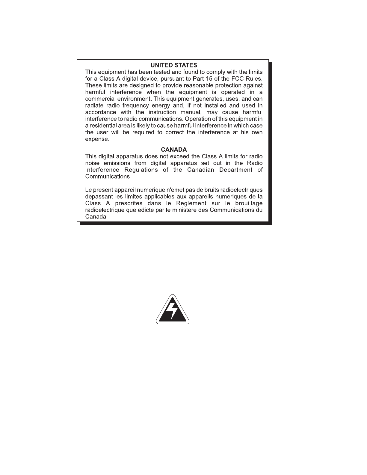
Cable Connections and Power Requirements
Make sure all cables are connected as shown in Figures 3-6.
Voltage to the Model 1040 must be 10-17 volts DC, negative ground only. If
voltage is between 9-10 volts, LOW.BAT is displayed on the indicator.
Dropping below nine volts will cause the Model 1040 to automatically shut
itself off, protecting the battery from being completely drained.
If voltage is above 17 volts, HI VOLT flashes on the the display. After ten
seconds the unit displays SHT.DWN and turns off.
If voltage is below nine volts, LOW.BAT flashes on the the display. After ten
seconds the unit displays SHT.DWN and turns off.
Figure 3
Bottom panel w/power, alarm, speed sensor, remote
display, 2 Com ports, and 7-pin J-box connections
Figure 4
Bottom panel w/power, alarm, speed sensor, remote
display, 2 Com ports, and 4-pin J-box connections
12
Model 1040/XL User’s Manual
Page 13
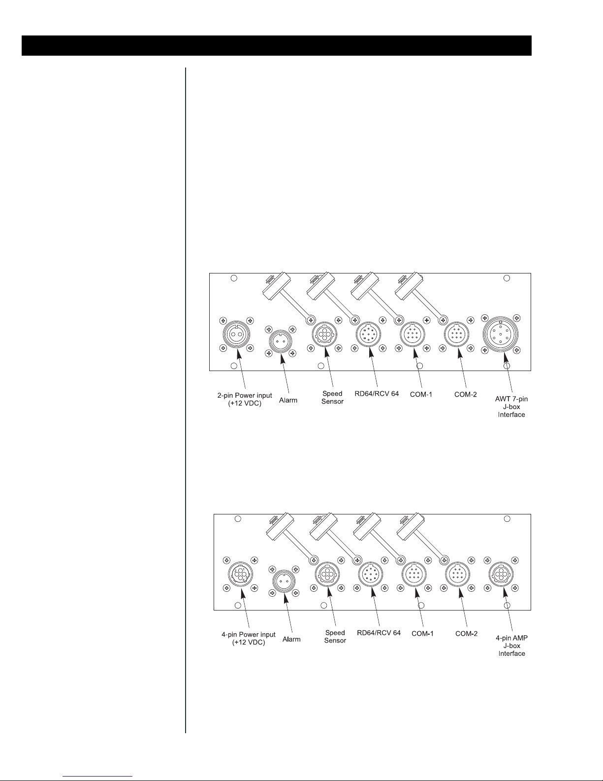
Figure 5
Bottom panel w/power, alarm, remote display, 1 Com
port, and 3 Weigh Bar connections
Figure 6
Bottom panel w/power, alarm, remote display, 1 Com
port, and 4 Weigh Bar connections
Model 1040/XL User’s Manual
13
Page 14
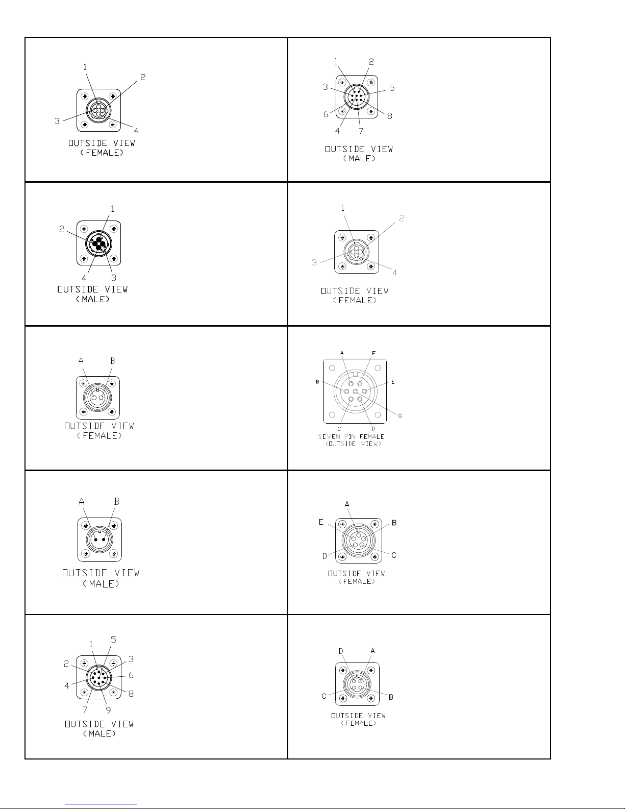
Speed Sensor Input
Pin Description
1 + 12V
2 GND
3 Input
4 N/C
RS-232 Port
Pin Description
1 CTS
2 XMT
3 RTS
4 RXD
5 GND
6 GND
7 +5V
8 +12V
4-Pin Power Input
2-Pin Power Input
2-Pin Alarm Input
Pin Description
1 +12V Input
2 GND
3 N/C
4 N/C
Pin Description
A +12V
B GND
4-Pin Amp J-Box Interface
Pin Description
1 + Excitation
2 - Bridge
3 + Bridge
4 -Excitation
7-Pin J-box Interface
Pin Description
A - Bridge
B + Excitation
C + Bridge
D - Excitation
E - Sense
F + Sense
G Shield
5-Pin Weigh Bar Input
Pin Description
A +12V Alarm
B GND
RD64/XL/M Input
14
Pin Description
1 +12V
2 +5V
3 Pwr Ret
4 GND
5 Seg Test
6 Data In
7 Clock
8 Load
9 Remote
Pin Description
A - Bridge
B + Excitation
C + Bridge
D - Excitation
E Shield
4-Pin Weigh Bar Input
Pin Description
A GND
BNA
CNA
DNA
Model 1040/XL User’s Manual
Page 15

Weighing Procedures
Simple Weighing
Loading/Unloading
Ingredients Into A Mixer
If you miskey, simply press
ZERO/CLEAR and re-enter the
proper amount.
1. Press the ON key. . .
Display shows M 1040 then HELLO, then weight value is displayed in the Gross mode. If it shows RETURN, press SELECT to
resume batching process, otherwise GROSS to return to Gross
mode.
2. Press the GROSS key. . .
Live scale weight is displayed in the gross weighing mode.
3. Press the ZERO/CLEAR key. . .
Zero value is displayed, and the system is zeroed.
Press PRINT to print the displayed weight value. Below is an example of a
printout:
10000 lb
1. Zero the indicator before loading first Ingredient.
2. Key in the target weight of the first ingredient. . .
Quantity to load/unload is displayed.
3. Press the LOAD/UNLOAD key. . .
Target weight remains displayed, and the load and alarm annunciator turns on. (this sequence now has the alarm setpoint engaged)
4. Start loading/unloading the first ingredient. . .
Display shows the net amount of what needs to be loaded/
unloaded, decreasing from target amount towards zero. (It doesn’t
matter if you are loading or unloading)
When displayed weight approaches within 50 lb/kg (default) of
your selected target weight, the alarm light starts flashing once/
sec. When your target is reached the alarm light stays on solid.
5. Stop loading/unloading when target weight is reached.
6. Press the GROSS key to shut off the alarm and the display will return to
the gross mode. Press ZERO/CLEAR to shut off alarm and remain in
the Load/Unload mode with the previous target amount active. This is
very handy for loading/unloading a series of equal amounts.
7. If AUTO-HOLD is enabled. . .
The alarm shuts off and the indicator goes into Auto-Hold mode,
displaying HOLD)
If AUTO-HOLD is off. . .
The alarm shuts off, and the unit returns to the gross mode.
8. Move mixer to its next ingredient loading/unloading location. . .
Display shows HOLD. Because the unit is in HOLD mode it will
not allow the display weight to change because of the terrain. This
will prevent a scale zero shift. Press MENU (or XM64) or GROSS
key to return to Gross mode.
Model 1040/XL User’s Manual
15
Page 16

Loading Or Unloading
Ingredients By Using the
XM64
You can load or unload a series of ingredients or batched feed by using the
XM64 transmitter/receiver. You must know the net amount to be loaded or
unloaded. The XM64 gives you the ability to tare or zero each ingredient and
view the net amount as you load or unload. The remote can also be used to
indicate the gross amount between ingredients and can return the indicator
to the gross mode when done loading by simply holding down on the XM64
for three or more seconds.
The alarm light is nonfunctional
in this loading/unloading
sequence.
Follow these steps:
1. Be sure the mixer or scale system is empty and zero the indicator.
2. Press the LOAD/UNLOAD key. . .
Zero value is shown, and the load and lb/kg annunciators turn on.
This means the net weighing mode is on.
3. Load or unload material as needed. . .
Net weight value increases. This is an absolute weight value. If
you are loading or unloading it shows the amount loaded or
unloaded so far.
4. When you reach the proper amount, stop loading or unloading material.
5. Press the ZERO/CLEAR button or the XM64 button. . .
The net value shown is reset or tared back to zero, ready for the
next amount.
You may view the gross weight by pressing and holding the XM64
button. If you release the button within three seconds, the unit
returns to the net mode showing zero.
If you are done loading and now want to return to the gross mode
for unloading, press and hold the XM64 button for more than three
seconds.
To return to the net mode, press LOAD/UNLOAD.
6. Load or unload additional quantities by repeating steps 3-5 as needed,
otherwise, if done loading, press the GROSS key to return to gross
weighing mode.
16
Model 1040/XL User’s Manual
Page 17

Operational Overview
Menus
The following is an operational overview of the 1040/XL indicator.
The indicator has the following menus:
• User menu (no password)
• Test menu (111 Menu)
• Setup menu (covered in the Service Manual)
• History menu (covered in the Service Manual)
• Factory calibration menu (covered in the Service Manual)
Gross Mode and
Power Failures
Data Entry
The standard mode of operation is the gross mode. The Gross annunciator
will be on and gross weight on the scale will be displayed.
After a power failure, when you power up the indicator you are given the
opportunity to return to the step in any process you may have been in when
the power failure occurred. This is important if you lose power in the middle
of a batch and simply want to return to which ingredient you were loading.
If power is lost during batching of a recipe, the display will show RETURN
when power is restored. If you want to exit the recipe process, press the
GROSS key. If you want to return to recipe process, press the SELECT key.
The indicator will return to where it was when power was lost. If you were in
the middle of loading an ingredient and don’t remember what ingredient it
was, press the LOAD/UNLOAD key to see the ingredient name.
All data entered will become one of the following:
• weight - All weight entered data will be rounded on a standard rounding
scheme to the nearest division size. (Example: If you enter 5002, and
the indicator is counting by 5’s, once the next key is pressed signifying
that it is weight, the display will show and record the entry as 5000).
• Time or Rotation entry
•Id
• Quick print number
• Recipe or Pen number
• Recipe entry (If entering a recipe, all data will be allowed down to 1 lb/
kg. Rounding will be implemented when actually batching or printing
recipes.
Anytime you enter data by mistake, the ZERO/CLEAR key will clear the data
entry display and you can re-enter the correct data.
Model 1040/XL User’s Manual
17
Page 18
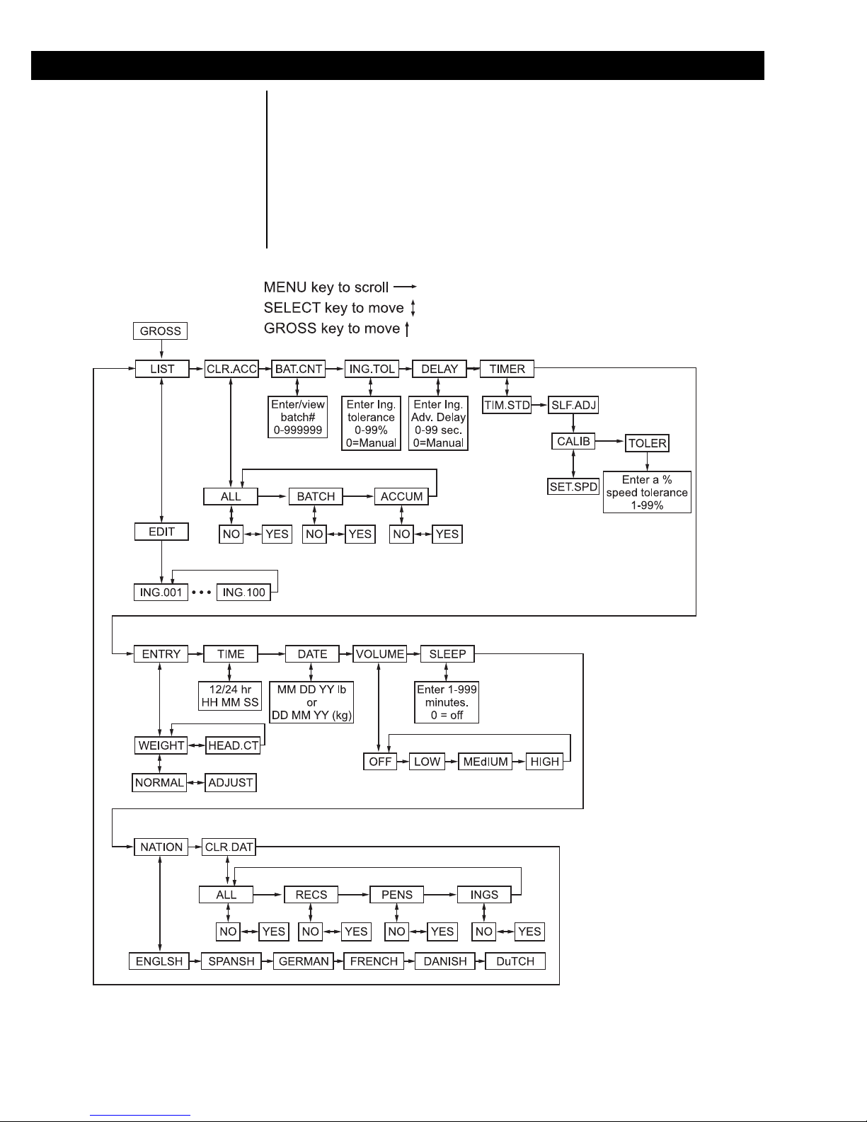
User Menu
Figure 7 shows the User menu. All the user configurable parameters are set
through this menu. This section deals with each of the items in the menu.
You will be referred back to Figure 7 several times.
Press the GROSS key repeatedly to escape from any spot
on the menu and return to the
Gross mode.
To enter the menu, press and hold the MENU key until you hear the unit
beep twice (2 seconds). Release the key and the display will show LIST.
Use the SELECT key to move down from a menu item. Use the MENU key
to move to the right in the menu. When you are done configuring one of the
menu items, press the GROSS key to move back up to the menu item.
18
Figure 7
User menu
Model 1040/XL User’s Manual
Page 19

LIST
To Set Ingredient Description Back to Default Setting
If you want to change back to
the default description, access
the proper ingredient and press
and hold the ZERO/CLEAR
key for 2 beeps and release.
ING.CLR will be briefly displayed and then returns to
EDIT.
To Setup Ingredient as an
Hand-add
While ingredient name is
displayed, press the HOLD key
and the Hand-add annunciator
will illuminate. The ingredient
will then always be treated as a
hand-add ingredient. Press the
HOLD key again to disable the
tagging of an ingredient as a
hand-add ingredient.
The first item in the user menu, Figure 7, is LIST. Use this to edit your
ingredient list. You can have up to 100 ingredients stored in the 1040. By
default the names are ING.001 through ING.100.
Follow steps 1 - 3 to access the
1. From gross weighing mode, press and hold MENU for 2 beeps. . .
LIST is displayed.
2. Press SELECT. . .
EDIT is displayed.
3. Press SELECT to access the first ingredient in the list. . .
ING.001 is displayed
OR
Key in the ingredient number you want to edit and press SELECT. . .
That ingredient is displayed.
You can enter alphanumeric titles for each ingredient using the
front panel keys. See the section Entering Alphanumeric Charac-
ters for instructions.
4. Once edited properly, press SELECT then MENU to access the next
ingredient in the list
OR
Press the GROSS key repeatedly to return to the gross weighing mode.
CLR.ACC
Once edited, these new ingredient descriptions will show up on all applicable
printouts and in the batching process.
The next menu item is CLR.ACC. Under this item you can choose to clear:
• ALL accumulators (the last 100 batch printouts/data and all ingredient,
recipe and pen accumulators)
• BATCH accumulator ((the last 100 batch printouts/data)
• ACCUM (the ingredient, recipe and pen accumulators).
Follow these steps:
1. From the Gross mode, press and hold the MENU key for two beeps (2
sec), then release. . .
LIST is displayed.
2. Press the MENU key once. . .
CLR.ACC is displayed
3. Press the SELECT key. . .
ALL is displayed.
4. Use the MENU key to move through the choices. Display the one you
want to clear and press SELECT key. . .
NO is displayed.
Model 1040/XL User’s Manual
19
Page 20

5. Press MENU and YES is shown. Press SELECT key. . .
WAIT is displayed while clearing, then ALL, BATCH, or ACCUM is
displayed.
6. Press GROSS key. . .
Unit returns to CLR.ACC.
7. Press the GROSS key to return to the gross weighing mode, or press
the MENU key to move to the next menu item.
BAT.CNT
The next menu item is BAT.CNT. This stands for Batch Counter. The
counter starts at 0 and increments each time a recipe is batched. This value
is cleared each time the batched data is cleared under CLR.ACC. This
counter goes up to 999999.
Follow these steps:
1. From the Gross mode, press and hold the MENU key for two beeps (2
sec), then release. . .
LIST is displayed.
2. Press the MENU key repeatedly until. . .
bAT.CNT is displayed.
3. Press the SELECT key. . .
Current batch counter is shown.
4. Press the SELECT key. . .
bAT.CNT is shown
5. Press the GROSS key to return to the Gross weighing mode or press
the MENU key to move to the next menu item.
ING.TOL & DELAY
20
ING.TOL stands for Ingredient Tolerance. DELAY stands for ingredient
advance Delay. These two parameters work together to make the Autoadvance feature work. Set ingredient tolerance as a percentage (1-99) and
delay in seconds. See example below to help understand these items.
Example: Delay parameter is set to 20 seconds
Follow these steps to set or view the ING.TOL parameter:
Tolerance is set to 5%
When the ingredient weight being loaded falls within the tolerance
and stays within the tolerance for the time set in the delay
parameter, the indicator will auto-advance to the next ingredient.
If you undershoot the ingredient tolerance, you can advance the
ingredient manually by pressing the MENU key on the 1040. If
you overshoot, the display will alternate between OVR.TOL and
the amount overloaded until the indicator doesn’t sense motion,
then it will advance to the next ingredient.
Model 1040/XL User’s Manual
Page 21

Auto-advance will take place
only if an ingredient tolerance
and an advanced delay parameter have values set at other
than 0. If either parameter is
set to 0, there will be no autoadvance.
1. From the Gross mode, press and hold the MENU key for two beeps (2
sec), then release. . .
LIST is displayed.
2. Press the MENU key repeatedly until. . .
ING.TOL is displayed
3. Press the SELECT key. . .
Current tolerance setting is displayed.
The default setting is 0 for both
parameters. This means autoadvance is disabled.
If an XM64 transmitter/receiver
is installed into the 1040, press
the XM64 button to advance to
the next ingredient. Do not use
auto-advance if the 1040
system has the XM64 option.
4. Use the keypad to enter in the new tolerance. . .
Entered tolerance value is displayed
5. Press the SELECT key. . .
ING.TOL is displayed
6. Press the MENU key to move to the DELAY menu item.
To set or view the DELAY parameter:
1. From the Gross mode, press and hold the MENU key for two beeps (2
sec), then release. . .
LIST is displayed.
2. Press the MENU key repeatedly until. . .
dELAY is shown
3. Press the SELECT key. . .
Current delay parameter is shown
4. Use the keypad to enter in the new setting. . .
Entered value is displayed.
TIMER
(Default setting = TIM.STD)
5. Press the SELECT key and. . .
dELAY is shown
6. Press the GROSS key to return to the Gross weighing mode or press
the MENU key to move to the next menu item.
This parameter sets the timer mode for standard time or self-adjusting time.
The self-adjust feature requires the mixer to be fitted with a proximity sensor
to sense the speed of the mixer. Consult nearest distributor.
To set the timer mode:
1. From the Gross mode, press and hold the MENU key for two beeps (2
sec), then release. . .
LIST is displayed.
2. Press the MENU key repeatedly until TIMER is shown
3. Press the SELECT key . . .
TIM.STD or SLF.ADJ is shown
Model 1040/XL User’s Manual
21
Page 22

4. Press the MENU key toggle between the choices.
5. Press SELECT when your choice is displayed. . .
If you select TIM.STD, TIMER is displayed.
If you select SLF.ADJ, CALIB is displayed. Use this to calibrate
the desired mixing speed. Press SELECT to enter calibration
mode.
SET.SPD is shown. Make sure the mixer is at the target speed
and press SELECT. The display will show SPD.CAL until there is
enough data to calibrate. The display will show CALIB when done.
Press the MENU key. . .
TOLER is displayed. Use this to set up the speed tolerance.
Press SELECT. . .
Enter the tolerance (1-99%)
Press SELECT. . .
Display shows TOLER.
6. Press the GROSS key repeatedly to return to the Gross weighing mode
or press the MENU key to move to the next menu item.
ENTRY
When a recipe is programmed,
it remembers the mode the
indicator was in at the time of
recipe creation. This means
you can have some recipes
based on head counts and
some based on weight.
IMPORTANT: Make sure
the indicator is configured
properly before entering
recipes.
ENTRY stands for the recipe entry mode. The indicator can accept recipes
in several ways. Below are explanations for each mode and examples to
illustrate. See note at left.
1. WEIGHT>NORMAL mode
This is used for entering batches based on weight or by percent-
age if adding up to 100, 1000 or 10000.
2. WEIGHT>ADJUST mode
This is based on weight or by percentage, same as #1 above. The
difference is that after the first ingredient is loaded, the rest of the
ingredients will be adjusted accordingly depending on how far off
the first ingredient was from the target. This maintains a proper
ration balance.
3. HEAD.CT mode
This mode is based on entering recipes with weight amounts to
feed 100 head.
Example 1: Entering a recipe by net weight (WEIGHT>NORMAL mode or
WEIGHT>ADJUST mode)
Use this method when you have a recipe set up by weight for
each ingredient such as:
22
Model 1040/XL User’s Manual
Page 23

4000 lb batch size
Ingredient 1 = 1000 lb corn
Ingredient 2 = 1230 lb hay
Ingredient 3 = 1450 lb silage
Ingredient 4 = 320 lb alfafa
total = 4000 lb
When this recipe is selected in the future, you can enter the
batch size you want and all ingredient amounts will be proportioned automatically.
Example 2: Entering a recipe by ingredient percentages
(WEIGHT>NORMAL mode or WEIGHT>ADJUST mode)
Use this method when you have a recipe set up by ingredient
percentages of a batch that adds up to 100, 1000, or 10000.
Enter the recipe by entering the percent of each individual
ingredient of the total batch so the total equals 100. Same
example as above would now be:
1. 2500 (represents 25.00% of corn)
2. 3075 (represents 30.75 % of hay)
3. 3625 (represents 36.25% of molass)
4. 800 (represents 8.00% of silage)
t 10000 (total % of all programmed ingredients)
Head count is limited to 999
head.
(Depending on how many digits are entered ex; 25.03 % can
be entered as 25, 250,or 2503 depending on accuracy. You
must make total add up to 100, 1000, or 10000.)
Example 3: Entering a recipe based on head count of animals (HEAD.CT
MODE). See note at left.
Use this when you want to mix a batch according to how
many animals can be fed. When you enter the recipe, the total
weight must add up to amount needed to feed 100 animals.
When you start a batch, type in the number of animals and
the total batch amount of the recipe will be automatically
calculated.
To setup for standard weight mode (ENTRY>WEIGHT>NORMAL):
1. From the Gross mode, press and hold the MENU key for two beeps (2
sec), then release. . .
LIST is displayed.
2. Press MENU repeatedly until ENTRY is displayed.
3. Press SELECT. . .
WEIGHT or HEAD.Ct is displayed.
4. Press MENU repeatedly until. . .
WEIGHT is displayed
5. Press SELECT. . .
NORMAL or ADJUST is displayed.
Model 1040/XL User’s Manual
23
Page 24

6. Press MENU until NORMAL is displayed
7. Press SELECT. . .
WEIGHT is shown.
8. Press GROSS key. . .
ENTRY is shown.
9. Press the GROSS key to return to the Gross weighing mode or press
MENU key to move to next menu item.
To setup for standard weight mode with auto-adjust (ENTRY>WEIGHT>
ADJUST):
1. From the Gross mode, press and hold the MENU key for two beeps (2
sec), then release. . .
LIST is displayed.
2. Press MENU repeatedly until ENTRY is displayed.
3. Press SELECT. . .
WEIGHT or HEAD.Ct is displayed.
4. Press MENU repeatedly until WEIGHT is displayed.
5. Press SELECT. . .
NORMAL or ADJUST is displayed.
6. Press MENU until ADJUST is displayed.
7. Press SELECT and WEIGHT is displayed.
8. Press GROSS key. . .
ENTRY is shown.
9. Press the GROSS key to return to the Gross weighing mode or press
the MENU key to move to the next menu item.
To setup for head count (ENTRY>HEAD.CT):
1. From the Gross mode, press and hold the MENU key for two beeps (2
sec), then release. . .
LIST is displayed.
2. Press MENU repeatedly until ENTRY is displayed.
3. Press SELECT. . .
WEIGHT or HEAD.Ct is displayed.
4. Press MENU repeatedly until HEAD.CT is displayed.
5. Press SELECT. . .
ENTRY is displayed.
6. Press the GROSS key to return to the Gross weighing mode or press
24
the MENU key to move to the next menu item.
Model 1040/XL User’s Manual
Page 25

TIME
The Model 1040 has battery backed time and date features. Printouts can
be configured for 24 hour or 12 hour styles but time must always be entered
as 24 hr style. Follow these steps:
1. From the Gross mode, press and hold the MENU key for two beeps (2
sec), then release. . .
LIST is displayed.
2. Press the MENU key repeatedly until TIME is displayed.
3. Press SELECT. . .
Current time is shown.
4. To change time enter HHMSS and press SELECT. . .
TIME is displayed
To leave time as it is, press SELECT. . .
TIME is displayed
5. Press the GROSS key to return to the Gross weighing mode or press
the MENU key to move to the next menu item.
DA TE
The indicator has battery backed time and date standard. The date can be
viewed or entered by following these steps:
1. From the Gross mode, press and hold the MENU key for two beeps (2
sec), then release. . .
LIST is displayed.
2. Press the MENU key repeatedly until DATE is displayed.
3. Press SELECT. . .
If pounds is the current unit of measure, MMddYY is displayed
momentarily, then the current date is displayed in MMddYY
format.
or
If kg is the current unit of measure, ddMMYY is displayed momen-
tarily, the the current date in ddMMYY format
4. To change the date, enter MMddYY if in lbs or enter ddMMYY if in kgs
and press SELECT. . .
DATE is displayed
To leave time as it is, press SELECT. . .
DATE is displayed
5. Press the GROSS key to return to the Gross weighing mode or press
the MENU key to move to the next menu item.
Model 1040/XL User’s Manual
25
Page 26

VOLUME
The Model 1040 has audible feedback on key presses that can be configured
for OFF, low, medium, and high volume.
(Default = high)
SLEEP
(Default = 0, for off)
1. From the Gross mode, press and hold the MENU key for two beeps (2
sec), then release. . .
LIST is displayed.
2. Press the MENU key repeatedly until VOLUME is displayed.
3. Press the SELECT key. . .
Current setting is shown
4. Press MENU repeatedly to scroll through choices. When you choice is
displayed, press SELECT. . .
VOLUME is displayed
5. Press the GROSS key to return to the Gross weighing mode or press
the MENU key to move to the next menu item.
The Model 1040 has a sleep mode that will shut the unit off if no keys are
pressed or the weight doesn’t change by more than 1% over the number of
minutes that you enter for the sleep setting.
1. From the Gross mode, press and hold the MENU key for two beeps (2
sec), then release. . .
LIST is displayed.
When the unit goes to sleep,
the unit will first activate the
audible alarm, and user has 10
seconds to press a key to reset
the SLEEP timer. If a key
hasn’t been pressed within
these 10 seconds the display
shows SHTDWN, and the unit
shuts off.
NATION
2. Press the MENU repeatedly until SLEEP is displayed.
3. Press the SELECT key. . .
Current setting is displayed
4. Use the keypad and enter in the sleep shutoff setting from 0-999
minutes. . .
Entered value is displayed.
5. Press the SELECT key. . .
SLEEP is displayed. If an invalid entry is attempted, CAN’T will be
displayed, and the user will need to enter a valid entry from 0-999.
6. Press the GROSS key to return to the Gross weighing mode or press
the MENU key to move to the next menu item.
The Model 1040 allows you to select a language for the display messages
that are spelled on the display, and for all the printouts that are available.
Choose from English, Spanish, German, French, Danish, and Dutch.
1. From the Gross mode, press and hold the MENU Key for two beeps (2
sec), then release…
LIST is displayed
2. Press the MENU key several times until….
26
NATION is displayed
Model 1040/XL User’s Manual
Page 27

3. Press the SELECT key…
Current setting is displayed.
4. Use the MENU keys and scroll to the proper language selection…
Proper selection is shown.
5. Press the SELECT key…
NATION is displayed.
6. Press the GROSS key…
Returns to the gross mode.
CLR.DAT
Used to clear all recipes programmed, all pens programmed, and all ingredient names.
1. From the Gross mode, press and hold the MENU key for two beeps (2
sec), then release. . .
LIST is displayed.
2. Press the MENU repeatedly until CLR.DAT is displayed.
3. Press the SELECT key. . .
ALL is displayed.
4. Use the MENU key to scroll through the choices of data you want to
permanently clear from memory. Choices are:
ALL All data is cleared.
RECS All recipes are cleared.
PENS All pen data is cleared.
INGS All ingredients are cleared.
5. Press the SELECT key when your choice is displayed. . .
NO is displayed.
6. Press MENU and YES is shown. Press SELECT key. . .
WAIT is displayed while clearing, then display shows ALL, RECS,
PENS or INGS.
7. Press the GROSS key to return to CLR.DAT.
8. Press the GROSS key to return to the Gross weighing mode or press the
MENU key to move to the next menu item.
This completes the User menu description.
Model 1040/XL User’s Manual
27
Page 28

Recipes and Pens
The 1040 can be programmed with 100 batching recipes. It can also track
the unloading of a batched load into 100 pens. Recipes and pens can be
custom named for ease of record keeping. This section covers the things
you need to know about recipes and using the pen features.
Recipe Features
Choose a Recipe Entry
Mode
Each recipe can draw from a list of 100 ingredients. All ingredients and
recipes can be labeled with up to six (6) alphanumeric character.
Recipes have the following features:
1. All recipes are based on weight (net or percentage) or head counts. See
the next section for details.
2. All recipes use the programmable pre-alarm warning light. This is
configured in the configuration menu. 50 lb/kg is the default value.
3. All recipes can use auto-hold capabilities if enabled in the configuration
menu.
4. One recipe can use a maximum of 32 ingredients.
5. Ingredients can be programmed to be hand-adds. This means they are
small preweighed items that once loaded into the mixer are recorded as
the programmed amounts in the recipe.
6. Recipes can use the auto-mix timer count down feature after the last
ingredient has been loaded. This must be enabled in the configuration
menu.
You need to choose the recipe entry mode in the User Menu. Choose
Weight (normal or auto-adjust) or Head Count. See the User Menu section
for information on these choices.
When a recipe is programmed, the indicator remembers which recipe
entry mode the indicator was in at the time of recipe creation. This
means you can have some recipes based on head counts and some
based on weight, if desired.
28
Model 1040/XL User’s Manual
Page 29

Recipe Menu
Creating A Recipe
100 ingredients standard.
ING.001 to ING.100.
Figure 8
Recipe Menu
Figure 8 shows the Recipe menu. You can refer to this menu as you go
through the process of creating recipes. The Model 1040 allows you to enter
100 recipes. You choose the ingredients for a recipe from the list of ingredients entered under LIST in the User menu. Once programmed, any recipe
can be quickly recalled for batching operations. Make sure you have the
recipe entry mode set as you wish before beginning. See Choose a
Recipe Entry Mode.
Following are the steps to creating a recipe:
1. From the Gross mode there are two ways to get to a recipe. Either key
in the number of the recipe you want to program and press and hold the
RECIPE key for two beeps (two seconds). . .
REC.XXX is displayed. XXX being the recipe number you keyed
in.
OR
Press and hold the RECIPE key for two beeps (two seconds). . .
REC.001 is displayed. This is the first of 100 recipes ready to be
programmed in a new indicator.
2. You can change the name of the recipe by using the keypad (See the
directions for entering alphanumeric characters found in Entering
Alphanumeric Characters.) Once completed go to step 3.
or
you can press SELECT to accept the default recipe name and go to
step 3..
Model 1040/XL User’s Manual
29
Page 30

3. If you are entering a new recipe T 0 will be displayed. This is where
the total weight of ingredients is shown for a recipe.
4. Press the SELECT key. . .
ING is displayed.
5. Use the keypad to enter an ingredient number (X) from the LIST (1-
100). . .
X is displayed.
6. Now press SELECT. . .
The ingredient name is shown momentarily. (ex: CORN-1) and
then. . .
AMOUNT is shown
7. Enter in amount of that ingredient. . .
Amount entered is shown
8. Now press SELECT. . .
ING is displayed
9. Repeat steps 5-7 until all ingredients are entered, then press
SELECT. . .
TXXXXX is displayed. XXXXX is the total amount of ingredients.
10. Press SELECT. . .
REC.001 (or your custom name) is displayed
11. Press MENU to move to the next recipe.
REC.002 is displayed (or your custom name)
12. Repeat above steps until all recipes are programmed.. Press GROSS to
exit from recipe programming mode.
30
Model 1040/XL User’s Manual
Page 31

Editing Operations
Following are instructions for several editing operations you may need to do
while maintaining your recipes and ingredient lists.
Deleting A Recipe
Changing Ingredient
Quantities
Deleting Ingredients
1. From Gross mode, enter the recipe #, then press and hold the RECIPE
key for 2 beeps (2 sec), then release.
2. Press and hold ZERO/CLEAR key for 2 beeps (2 sec). . .
REC.CLR is shown and then the recipe name is shown.
3. Press the GROSS key to return to the Gross weighing mode.
1. Access the recipe you want to edit, see Figure 8, and use the SELECT
and MENU key to view the ingredient you want changed.
Press SELECT. . .
Ingredient amount is displayed.
2. Use the keypad to enter in a new amount then press SELECT. . .
Ingredient is displayed
3. Press the GROSS key to return to the Gross weighing mode.
Access the recipe you want to edit, see Figure 8, and use the MENU and
SELECT keys to display the ingredient name you want deleted. Press and
hold ZERO/CLEAR for two beeps ( 2 sec) and release the key.
Inserting Ingredients
Ingredient is deleted and next ingredient is shown.
Doing an insert will insert the new ingredient in front of the displayed ingredient.
1. Access the recipe you want to edit, see Figure 8, and use the MENU
and SELECT keys to display the ingredient name where you want to
insert the new ingredient.
2. Press and hold SELECT until ING is displayed.
3. Use the keypad to enter in the ingredient number (X) of a valid ingredient from the LIST (1-100). . .
X is displayed.
4. Press SELECT. . .
Ingredient name is shown momentarily (ex: CORN-1) and then
AMOUNT is shown.
5. Enter in amount of that ingredient. . .
Amount entered is shown.
6. Press SELECT. . .
Next ingredient in the recipe is shown.
7. Press GROSS to return to the gross weighing mode.
Model 1040/XL User’s Manual
31
Page 32

Pens
Pens are used to track the unloading of finished batched recipes. You can
store unloading data for up to 100 pens. This data is saved and can be
printed. Data saved and printed includes the date, time, pen number, pen
description, weight unloaded and total unloaded.
Editing Pen Descriptions
If you enter a number higher
than 100, CAN’t will be displayed and the display will
return to the previous display.
The default names for pens are PEN.001, PEN.002, etc. Follow these steps
if you want to customize the name to a six (6) character description.
1. From the Gross mode, enter pen number (example:56), than press and
hold on PEN key for two beeps (2 sec) then release. . .
PEN.056 is displayed.
2. Use the keypad to enter in the description (example: PIG-01). Press the
6(PQR) key twice to display..
__ __ __ __ __ P. See section Entering Alphanumeric Characters
3. Press the 3(GHI) key three times to display. . .
__ __ __ __ P I is shown.
4. Wait three seconds so the display has time to move the PI to the left
and the flashing cursor will appear to the right. You need to do this on
this keying sequence because I and G are on the same key. See section
Entering Alphanumeric Characters.
Continue keying in characters until PIG-01 is displayed.
5. Press SELECT. . .
PIG-01 is displayed, then press MENU and PEN.057, the next
pen, is displayed.
6. Repeat steps 2-5 until all pen names have been been properly edited
and press MENU to scroll through and view all pen descriptions.
To edit the Pen description, display the desired pen and use the keypad
to change the description. If you want to change back to the default
description simply access the desired pen name and press and hold the
ZERO/CLEAR key for 2 beeps (2 sec) PEN.CLR is displayed and then
the next Pen description is shown.
7. Press GROSS to return to Gross weighing mode.
32
Model 1040/XL User’s Manual
Page 33

Using ID
The Model 1040 has a generic six digit ID that can be used as an operator
ID number. This needs to be entered before doing any batching operations
so the user is identified. This ID will be printed on the reports or transferred
to the TDM-40.
Entering an ID
This ID is active on all printouts
until it is changed or cleared
from the indicator
Viewing Current ID
Clearing Current ID
To enter an ID number follow these steps:
1. From the Gross mode, enter the ID #, then press the ID key. . .
ID number is displayed for two seconds, then the display returns
to the Gross mode.
1. From the Gross mode press the ID key. . .
Current ID is displayed
2. Press the GROSS key to return to the Gross mode.
1. Press the ID key. . .
Current ID is displayed. If no ID exists, display shows NO ID, for
two seconds and returns to Gross mode)
2. Press the ZERO/CLEAR key while the ID Is displayed. . .
NO ID is displayed, and returns to the Gross mode.
Model 1040/XL User’s Manual
33
Page 34

Other Operations
This section covers the variety of other operations available with the Model
1040.
Manual Hold Mode
When using the hold mode,
you must be sure to deactivate
hold mode when loading or
unloading the mixer.
Batching Recipe
(Ingredient Loading
Method)
Make sure indicator is set
properly to either weightnormal, weigh-adjust, or
head count before beginning. Also make sure editing
of recipe names has already
been done before starting.
Auto holding within the recipe mode was discussed in an Loading/Unloading
Ingredients Into A Mixer. There is also a manual hold using the HOLD key
to prevent a zero shift from occurring while moving a portable TMR mixer
system over rough farm terrain.
Follow these steps:
1. In the Gross mode ,before moving the mixer system press HOLD. . .
HOLD will be displayed
2. Now move the system and when reaching the new loading or unloading
point, press either the HOLD or GROSS key. . .
Gross weight will be displayed.
Recipe ingredient loading will provide the following:
• Consistency in the batching operation
• 100 recipe and 100 ingredient capabilities (32 ingredients max/recipe)
• Simplifies the entire batching process
• Track feeder accuracy (ID feature)
• Gives you a low cost record keeping option
• Automatically calculates new ingredient amounts when changing batch
size.
• Automatically records feed, recipe, and pen usages, with dates and
times.
• Can automatically put the feeder into a mix cycle, (either time or
number of rotations)
1. While in the Gross weighing mode, enter the number of the desired
recipe, and press RECIPE. . .
Recipe name is displayed.
2. Press the LOAD/UNLOAD key. . .
34
Either go to step 2 , or use the menu key to scroll to other recipes.
The following is displayed
a. WT.AMT
b. ADJ.AMT
c. HD.AMT
or
NOPRGM (This is displayed if that recipe is not programmed)
If you need to enter or change the total amount to be batched or
the number of head, enter the new amount and press SELECT.
Otherwise proceed to next step.
If you attempt to enter a weight amount above the capacity
parameter or a head count amount larger than 999, the display
will show CAN’T. Edit amount, and then press the SELECT key.
Model 1040/XL User’s Manual
Page 35

3. Press the LOAD/UNLOAD to initiate the loading of the first
ingredient. . .
First ingredient description is shown alternating on display with
target amount. Example: Corn-1>3000>Corn-1>2800, etc.
At this point the time will be recorded as the time when the
ingredient was started to be saved and printed, or transferred to
TDM-40, printer or computer.
4. Begin loading the amount displayed. . .
As loading occurs the target weight goes down. Once the target
has dropped by more than 25% only the target value will remain
displayed. The display will no longer flash back and forth. (This is
a programmable parameter under 1040 MENU - NAME)
5. Stop loading the ingredient when you notice that the target weight has
been met. . .
Display shows 0.
6. Depending on the system configuration. . .
A. Auto advance- User can enter tolerance and ad-delay parameters under the user menu.
Once advancing to the next
ingredient it will record the
previous Ingredients actual
amount loaded into the ingredient accumulators.
If target stays within the tolerance (ING.TOL)setting, and within
advance-delay (dELAY) parameter, the system will automatically
advance to the next ingredient. If target goes over or under user
must use the MENU key to advance forward on the indicator.
(AUTO-HOLD DOESN”T FUNCTION IN THIS MODE).
B. Manual Advance Method- When amount loaded is close as
possible, either press the MENU key on the model 1040, (or the
XM64 transmitter /receiver if installed), from the front end loader
to advance to the next ingredient.If AUTO-HOLD is turned on user
will press the key once to get into the hold mode. Now the system
can be moved and not affect the target value because of zero shift
from moving the mixer. Display will show HOLD. Pressing the key
again once the system has been moved, will now move to the next
ingredient. If this is the last ingredient, the unit will return to Gross
weighing mode.
Please remember a hand-add ingredient is a small ingredient that
when added will be recorded always as target amount instead of
actual amounts.
7. Repeat steps 4-6 until all ingredients are properly loaded.
8. If configured for AUTO-mix, after the last ingredient Is loaded, pressing
the MENU key or the XM64 will access the mix timer countdown. . .
either ST: XX:XX for self adjusting time
Or TC: XX:XX for standard timer
After mixer counts down, alarm light comes on, and unit will return
to the gross mode after pressing the MENU, or GROSS key.
9. Now proceed to unload to the appropriate pen. (SEE SECTION ENTITLED PEN UNLOADING)
Model 1040/XL User’s Manual
35
Page 36

10. Also if unit is setup for AUTO-PRINT, the following printout will be
printed if a printer is installed:
10/08/01 Batch
Id Number: 123456
Recipe 1: FR-COW
Load Amount: 10000 lb
Time Description Target Actual
12:01
PM CORN 4000 lb 3900 lb
12:10 PM HAY-1 3000 lb 3030 lb
12:20 PM COTTON 3000 lb 2980 lb
TOTAL 10000 lb 9910 lb
Time Pen Name Target Actual
12:40 PM PEN-1 5000 lb 5050 lb
12:50 PM PEN-2 5000 lb 4900 lb
1
Mix Timer Operation
Time Mix
The Model 1040 has a mix timer feature that can be configured for one of
two methods; Time mix or Self Adjust Time.
After a batch is loaded, you can activate a timer, or the Model 1040 can be
configured to activate the timer automatically.
Configure this under user’s menu-TIMER/TIME. MAX time = 5959, or 59
minutes and 59 seconds. Invalid data entry will be displayed as CAN’T. You
need to clear the data and re-enter it as a valid time.
1. From the gross mode, enter in timer in minutes/seconds. . .
MMSS is displayed
2. Press the TIMER key. . .
TC MM:SS is displayed for three seconds, and then starts count-
ing down. When the end of the timer cycle is reached the red
alarm light is lit.
3. Press the GROSS key to disable and return to the Gross mode.
To view the current timer setting:
1. From Gross mode, press TIMER. . .
TC MM:SS is displayed (MM:SS is the last entered value) for three
seconds, then timer starts to count down.
2. Press GROSS to return to the gross mode.
36
Model 1040/XL User’s Manual
Page 37

Self Adjust Time This option requires that a magnetic proximity sensor be installed onto the
mixer to provide speed inputs to the Model 1040 every time a full rotation is
detected. Overall operation is the same as standard time, but will adjust
depending on speed.
The target speed must have been calibrated prior to correct operation.
1. Press the TIMER key. . .
SPD.CAL is shown while the speed of the mixer is calculated.
Then, the new adjusted time is shown; ST:MM:SS and the timer
will count down.
The operation from this point is the same as standard Time Mix.
Pen Unloading
The Model 1040 can keep track of amounts unloaded to 100 different pens.
Make sure all pens have been tagged with customized pen names as
described in Editing Pen Descriptions, otherwise pen names will have
default names, PEN.001, PEN.002, etc.
1. Now with mixer full of a batched amount, and properly mixed, select an
unload pen number. . .
Pen number is shown
2. Press the PEN key. . .
Pen description is shown.
3. Press the LOAD/UNLOAD key. . .
Current unload amount is displayed.
If you need to enter or change the total amount to be unloaded to
the pen, enter the new amount and press SELECT. Otherwise
proceed to next step.
If attempting to enter a weight amount above the overcapacity
parameter the display will show CAN’T. Edit amount properly and
then press the SELECT key
Model 1040/XL User’s Manual
37
Page 38

4. Press the LOAD/UNLOAD to initiate the unloading to the pen. . .
The pen description is shown alternating on the display with
entered target amount. PEN-01>10000>PEN-01>9000, etc.
At this point the time needs to be saved in memory, for printing or
transfer to the TDM-40 or computer.
5. Begin unloading the amount displayed. As unloading takes place target
also goes down. Once the target has dropped by more than 25% only
the target value will remain displayed.
6. Stop unloading when the user notices on the display that the proper
unload target has been met. . .
Display shows 0.
Press GROSS key to abort
the loading process.
Example:
Loading/Unloading Printout:
7. Press MENU to accept amount unloaded and return to the Gross mode.
If a person wants to unload to another pen, then repeat steps 1-7.
At this point the actual amount unloaded to a pen is recorded.
8. If system has been set for autoprint, the following typical prints outs will
have been printed as they went through the process.
10/08/01 Batch 1
Id Number: 123456
Recipe 1: FR-COW
Load Amount: 10000 lb
Time Description Target Actual
12:01 PM CORN 4000 lb 3900 lb
12:10 PM HAY-1 3000 lb 3030 lb
12:20 PM COTTON 3000 lb 2980 lb
TOTAL 10000 lb 9910 lb
Time Pen Name Target Actual
12:40 PM PEN-1 5000 lb 5050 lb
12:50 PM PEN-2 5000 lb 4900 lb
38
Model 1040/XL User’s Manual
Page 39

Viewing the
Accumulators
The Model 1040 automatically records ingredient, recipe and pen usage
when using recipes and pen unload features. The following describes how to
view the accumulators on the indicator. Refer to Figure 9.
Usage Accumulator
Model 1040/XL User’s Manual
Figure 9
39
Page 40

Viewing the Ingredient
Usage Accumulators
To quickly go to specific
ingredient accumulator, from
TOTAL, enter ingredient
number and press SELECT.
The ingredient description is
displayed.
1. From the Gross mode, press the USAGE key. . .
INGRED is displayed. Refer to Figure 9.
2. Press the SELECT key. . .
TOTAL is displayed.
3. Press the SELECT key. . .
The total of all the ingredients is displayed.
4. Press the SELECT key . . .
TOTAL is displayed
OR press the MENU key. . .
ING.XXX is displayed
5. Press the MENU key several times until the ingredient to view is dis-
played. . .
ING.XXX is displayed.
6. Press the SELECT key . . .
ING XXX accumulator is displayed.
7. Press the SELECT key . . .
ING.XXX is displayed
Viewing the Recipe
Usage Accumulators
To quickly go to specific recipe
accumulator, from TOTAL,
enter recipe number and press
SELECT. The recipe description is displayed.
OR press MENU key. . .
ING.YYY is displayed
8. Repeat steps 6-7 until done viewing accumulators.
9. Press GROSS. . .
INGRED is displayed.
10. Press GROSS to return to the gross weighing mode.
1. From the Gross mode, press the USAGE key. . .
INGRED is displayed. Refer to Figure 9.
then press the MENU key. . .
RECIPE is displayed.
2. Press the SELECT key. . .
TOTAL is displayed.
3. Press the SELECT key. . .
The total of all the recipes is displayed.
4. Press the SELECT key . . .
40
TOTAL is displayed
OR press the MENU key. . .
REC.XXX is displayed.
Model 1040/XL User’s Manual
Page 41

5. Press the MENU key several times until the recipe to view is
displayed. . .
REC.XXX is displayed.
6. Press the SELECT key . . .
REC XXX accumulator is displayed.
7. Press the SELECT key . . .
REC.XXX is displayed
OR press MENU key. . .
REC.YYY is displayed
8. Repeat steps 6-7 until done viewing accumulators.
9. Press GROSS. . .
RECIPE is displayed.
10. Press GROSS to return to the gross weighing mode.
Viewing the Pen
Accumulators
To quickly go to specific pen
accumulator, from TOTAL,
enter the pen number and
press SELECT. The pen
description is displayed.
1. From the Gross mode, press the USAGE key. . .
INGRED is displayed. Refer to Figure 9.
then press the MENU key twice. . .
PENS is displayed.
2. Press the SELECT key. . .
TOTAL is displayed.
3. Press the SELECT key. . .
The total of all the pens is displayed.
4. Press the SELECT key . . .
TOTAL is displayed
OR press the MENU key. . .
PEN.XXX is displayed
5. Press the MENU key several times until the pen to view is
displayed. . .
PEN.XXX is displayed.
6. Press the SELECT key . . .
PEN.XXX accumulator is displayed.
7. Press the SELECT key . . .
PEN.XXX is displayed
OR press MENU key. . .
PEN.YYY is displayed
8. Repeat steps 6-7 until done viewing accumulators.
9. Press GROSS. . .
PENS is displayed.
10. Press GROSS to return to the gross weighing mode.
Model 1040/XL User’s Manual
41
Page 42

The XM64
Transmitter/Receiver
The XM64 transmitter serves a variety of functions depending on the mode
the indicator is setup for. The STD configuration parameter sets the transmitter so it acts as follows:
1. If you are doing mixer loading (Load/Unload mode):
If you press and release the clicker, the indicator tares to 0.
If you hold the clicker down for more than a second, gross weight is
displayed as long as the clicker button is depressed.
If you hold the clicker button for more than three seconds, the unit
remains in the GROSS mode.
2. If the indicator is in recipe or pen mode:
Press the clicker to advance to the next ingredient. If the last ingredient
or pen is being displayed, it advances to the Gross mode.
If unit is set for AUTO-HOLD the XM64 needs to be pressed twice. If
not the XM64 only needs to be pressed once.
Printing
QUICK PRINT 1 (Prints
active ingredient listing)
Any ingredient tagged with an
(*) means it is a pre-weighed
hand-add ingredient. When
used in a recipe, it will be
saved in the accumulators as
the target value not the actual.
Press the PRINT key from Gross Load/Unload mode to print the displayed
weight.
10000 lb
There are nine Quick Prints. These are nine preset print formats. Each is
explained below.
To perform a Quick Print key in the desired number (1-9), then press
SELECT, then PRINT.
Printouts fit on a 40 character WP-233 printer.
Using the Quick Prints, you can transfer appropriate data to WP-233 printer,
TDM-40 (Transfer Data Module) or a computer.
03-18-03 10:03 AM
Ingred.# Description
1 CORN
2 HAY-1
3 COTTON
4 BARLEY
5 MOLASS
6 SILAGE
7 CORN-2
8 S-BEET
9 FHAY
10 HAY-2
42
Model 1040/XL User’s Manual
Page 43

QUICK PRINT 2
(Prints active unload pen
listing, ones that have a
target value.)
10-18-01 11:50 AM
Pen# Description
1. PEN-1
2. PEN-2
3. PEN-3
4. PEN-4
5. SMITH
6. CUST-1
7. CUST-2
QUICK PRINT 3:
(Prints all Recipes)
If recipe was created with Head
Count as the entry method,
Load Amount will be replaced
by Head Count in the sample
at right.
QUICK PRINT 4:
(Prints last 100 batches)
If recipe was created with Head
Count as the entry method,
Load Amount will be replaced
by Head Count in the sample
at right.
10-18-01 3:00 PM
Recipe 1: FR-COW
Load Amount: 10000 lb
Ingred. Description Target
1 CORN 4000 lb
2 HAY-1 3000 lb
3 COTTON 3000 lb
Total 10000 lb
10/08/01 Batch 1
Id Number: 123456
Recipe 1: FR-COW
Load Amount: 10000 lb
Time Description Target Actual
12:01 PM CORN 4000 lb 3900 lb
12:10 PM HAY-1 3000 lb 3030 lb
12:20 PM COTTON 3000 lb 2980 lb
TOTAL 10000 lb 9910 lb
Time Pen Name Target Actual
12:40 PM PEN-1 5000 lb 5050 lb
12:50 PM PEN-2 5000 lb 4900 lb
Model 1040/XL User’s Manual
43
Page 44

QUICK PRINT 5
(Prints a listing of all active
ingredient accumulators
with usage)
QUICK PRINT 6
(Prints a listing of Recipe
Accumulators with usage)
10-17-02 6:00 AM
Ingred. Description Usage
1 CORN 17000 lb
2 HAY-1 6000 lb
3 COTTON 5000 lb
4 BARLEY 4000 lb
5 MOLASS 4000 lb
6 SILAGE 1000 lb
7 CORN-2 20000 lb
8 S-BEET 30000 lb
9 FHAY 40000 lb
10 HAY-2 50000 lb
Total 177000 lb
10-17-02 6:20 AM
Recipe Description Usage
1 FR-COW 20000 lb
2 H-COW 22000 lb
Total 42000 lb
QUICK PRINT 7
(Prints a listing of Pen
Unloading Accumulators
with usage)
44
10-18-02 11:00 AM
Pen # Description Usage
1 PEN1 20000 lb
2 PEN2 22000 lb
Total 42000 lb
Model 1040/XL User’s Manual
Page 45

QUICK PRINT 8
(Prints the Recipe/Ingredient
Accumulators)
12-07-02 08:07 AM
Recipe 1: REC.001
Ingred. Description Usage
30 ING.030 10000 lb
40 ING.040 10000 lb
50 ING.050 10000 lb
60 ING.060 10000 lb
Total 40000 lb
Recipe 2: REC.002
Ingred. Description Usage
15 ING.030 10000 lb
20 ING.020 25000 lb
40 ING.040 30000 lb
50 ING.050 15000 lb
Total 80000 lb
Model 1040/XL User’s Manual
45
Page 46

QUICK PRINT 9
(Parameter Printout)
Ready...
System Configuration Settings
03-18-03 01:04 PM
User,s Menu
Batch Cntr: 0
Tolerance: 0
Delay: 0
Timer: TIME
Time: 05:00
Entry: WEIGHT
Mode: NORMAL
Time: 01:04 PM
Date: 03-19-03
Volume: HIGH
Sleep: 0
Nation: ENGLSH
1040 Menu
Firmware Rev: 55422-0012A
Basic App Rev: 155799 0A
Config Number: 10000
Custom: 0
O-cap: 2000
Clock: 12 Hr Format
Alarm: 50
Name Flash: ON
Input: STD Mode
Input2: STD Mode
Update: 2
Average: 30
FILTER
Const: 4
Window 0
AZT: 0
Stable: 0
RS232.1
Baud: 9600
Parity: NONE
Data: 8 bits
Handshake: NONE
Layout: STD
Auto: OFF
RS323.2
Baud: 9600
Parity: NONE
Data: 8 bits
Handshake: NONE
Layout: OFF
Auto: OFF
46
Model 1040/XL User’s Manual
Page 47

Indicator Diagnostics
The test mode is used to test various functions of the 1040 Indicator. The
test menu is shown in Figure 10. Instructions for using the test menu are
found below.
Access the Test Menu
Figure 10
Test Menu (password 111)
You can test the following functions of the indicator with this menu:
VOLTS Monitor the input voltage of the indicator
LCD Perform a test of the LCD display
KEYPAD Peform a key test
A/D Test the Analog to Digital function
SERIAL Check serial ports 1 and 2
INPUTS Check the 7 TTL inputs (INPUT.1 is XM64, SPEED is for Self
Adjusting Time mode.
RELAY Check the alarm relay
SOFT Verify the software verision of the indicator
Use the MENU and SELECT keys to navigate the menu shown in Figure 10
Step by step instructions appear below.
1. Press and hold the MENU key for 3 beeps (about 3 seconds). Release
the key. . .
SET.PAS is displayed.
2. Key in the password, 111, and press the SELECT key. . .
VOLTS is displayed.
Model 1040/XL User’s Manual
47
Page 48

Volts test
3. This allows you to check the 12 VDC input voltage the Model 1040 is
receiving. With VOLTS displayed, press the SELECT key. . .
Current voltage is displayed.
Press the GROSS key twice to return to gross weighing mode
or
Press SELECT to return to the VOLTS display.
LCD test
4. From VOLTS display, press the MENU key. . .
LCD is displayed. Use this to perform a self-test of the LCD
display, complete display test or segment test.
5. Press the SELECT key. . .
TEST is displayed.
6. Press the SELECT key. . .
Display performs a display test for 15 seconds then TEST is
displayed.
7. Press the MENU key. . .
SEGMNT is displayed.
8. Press the SELECT key. . .
Display performs a segment test for 70 seconds then SEGMNT is
displayed.
9. Press the GROSS key to return to the LCD display. From here you can
Press the GROSS key again to return to gross weighing mode
or
Press MENU to advance to next menu item. . .
KEYPAD is displayed.
Keypad test
A/D test
10. This allows you to test all the active keys. With KEYPAD displayed,
press the SELECT key. . .
HIT.KEY is displayed momentarily then NO KEY is displayed. This
remains on the screen until a key is pressed. Press any key to see
an echo of its name on the display. CAUTION: If you press the
MENU key you will exit the test.
11. Press the MENU key to stop the test. . .
KEYPAD is displayed.
12. Press the GROSS key to return to gross weighing mode
or
Press MENU to advance to next menu item. . .
A/D is displayed.
13. Use this to see the actual A/D raw counts value on the display. From
A/D display, press the SELECT key. . .
CNTS is shown momentarily then the actual A/D raw counts.
14. Press the SELECT key. . .
MV/V is shown momentarily then the actual mV/V reading is
shown.
48
Model 1040/XL User’s Manual
Page 49

15. Press the SELECT key. . .
A/D is shown.
16. Press the GROSS key to return to gross weighing mode
or
Press MENU to advance to next menu item. . .
SERIAL is displayed.
Serial test
17. Use this to test the serial ports. From SERIAL display, press the
SELECT key. . .
PORT 1 is displayed.
18. Press the SELECT key. . .
NOLOOP is displayed.
19. Short the XMT to RCV lines. . .
LOOP should be displayed.
20. Press SELECT. . .
PORT 1 is displayed.
21. Press the MENU key. . .
PORT 2 is displayed.
22. Repeat steps 18-20. . .
PORT 2 is displayed.
23. Press the GROSS key to return to gross weighing mode
or
Press MENU to advance to next menu item. . .
INPUTS is displayed.
Inputs test
24. Use this to test the inputs in the 1040. From the INPUTS display, press
the SELECT key. . .
IN.1 is displayed.
25. Press the SELECT key. . .
OPEN or CLOSED is displayed.
26. Press the SELECT key. . .
IN.1 is displayed.
27. Press the MENU key. . .
IN.2 is displayed.
28. Press the SELECT key. . .
OPEN or CLOSED is displayed.
29. Press the SELECT key. . .
IN.2 is displayed.
Model 1040/XL User’s Manual
49
Page 50

Relay test
Soft test
30. Repeat steps 27-29 until all inputs are checked.
31. Press the GROSS key to return to INPUTS and then press MENU to
advance to next menu item. . .
RELAY is displayed
or
Press the GROSS key to return to gross weighing mode.
32. Use this to test the alarm light relay. From RELAY display, press the
SELECT key. . .
ON/OFF is displayed. While this is displayed the alarm light
should flash two times per second.
33. Press the SELECT key. . .
RELAY is displayed.
34. Press the GROSS key to return to gross weighing mode
or
Press MENU to advance to next menu item. . .
SOFT is displayed.
35. Use this to view software version information for the 1040. From the
SOFT is display, press the SELECT key. . .
PART is displayed.
36. Repeatedly press the MENU key to view all the information available.
When you have gone through all the displayed information, SOFT is
displayed.
37. Press the GROSS key to return to gross weighing mode
or
Press MENU to advance to return to the first menu item. . .
VOLTS is displayed.
50
Model 1040/XL User’s Manual
Page 51

RD64/XL/M Remote Displays and XM64 Remote Transmitter
Remote Displays
RD64XL remote display
(XM64 optional)
The RD64/XL/M are remote displays that are compatible with the Model
1040. See Figure 12. (An RD64 output option is required on the Model 1040
for interfacing.) The interface cable plugs directly into the bottom of the
Model 1040. Any data displayed on the Model 1040 is also displayed on the
RD64.
RD64 remote display
(XM64 optional)
XM64 Remote
Transmitter/Receiver
RD64M remote display
(Mirror mount)
Figure 12
Remote Dispays
An optional radio remote transmitter and receiver (XM64)
can be installed in either the RCV-64 or the RD64XL.
This option lets the user
tare and manually advance to the next ingredient from a remote location, usually a front-end
loader.
<RCV-64 XM64>
Model 1040/XL User’s Manual
51
Page 52

Troubleshooting
If you experience problems in the operation of your system, read through
these troubleshooting steps and perform those which are appropriate. This
information may help you to correct the following operational difficulties
without calling your supplier or sending your equipment in for repair:
• Power-on
• Indicator Over or Under Capacity
• Inaccurate Weight Readings
• Measuring the Supply Battery Voltage
Instructions for sending an indicator in for repair are provided in the last
section under Service Repairs.
Power-On
If your indicator does not power-on, check the following possible problem
sources in the order given. Attempt to power-on after trying each of these
four troubleshooting steps:
1. Check Battery Voltage. Required voltage is 10-17 volts DC negative
ground. If the voltage is between 9-10 volts, the indicator will display
LOW.BAT. The indicator will automatically turn off if the incoming
voltage drops below nine volts or rises above 17 volts.
2. Disconnect and Check Power Cable Connector at the vehicle or AC
to DC converter, clean if necessary, and reconnect.
3. Replace Fuse. Sometimes, a bad fuse can be recognized by an obvious
break in the wire filament. However, such a break is not always observable, and getting a successful power-on after changing a fuse is often
the only way of knowing that the fuse was indeed defective.
Make sure the new fuse is the proper size and has a current rating of
five amperes. Using a fuse with too high a current rating can cause
costly damage to the indicator and will void your warranty. The same is
true for substituting wire, a nail, or any other object in place of a fuse.
Place nothing in the fuse connector except a proper fuse.
Try to power-on after changing the fuse (see instructions below for
replacing the fuse).
To replace the fuse, remove the 12 front panel screws.
4. Test Indicator and Cables to isolate the source of the problem.
52
1. Flip front panel out.
2. Locate fuse in lower corner of main PC board.
3. Pull blown fuse out and replace.
4. Re-install and tighten the 12 front panel screws.
a. Disconnect all cables on bottom panel of Indicator except for power
cable. Do disconnect Weigh Bar
remote display cable, etc.
b. Now try powering-on. If this is not successful, your problem is in the
indicator and you should contact your supplier.
c. If you are able to power-on with only the power cable connected, your
problem is probably not in the indicator; continue troubleshooting.
Model 1040/XL User’s Manual
®
cables, and, if present, alarm cable
Page 53

d. With power still on, plug in cables, one at a time — Weigh Bar
cables first, then alarm cable, then printer/remote display cable, etc.
— until plugging in one of the cables causes the indicator to shut off.
That cable is the bad one and needs to be repaired or replaced.
®
Indicator Over/Under
Capacity
An over-ranged indicator is represented by upper dashes or lower dashes.
®
1. Test the Weigh Bar
cables to isolate the source of the over-range
problem, as follows:
a. Disconnect all Weigh Bars
®
.
b. Try to zero the indicator by pressing GROSS and CLEAR.
• If you are unable to zero the indicator with the Weigh Bars® disconnected, the problem is in the indicator and you should contact your
supplier.
• If you are able to zero your indicator with the Weigh Bars® disconnected, then the problem is probably in the Weigh Bars® and you
should continue troubleshooting.
2. Reconnect all Weigh Bars®. You will see upper or lower dashes displayed again.
3. If your Weigh Bar®connectors have the four-pin configuration, disconnect one Weigh Bar® and connect an adapter plug in its place.
If your Weigh Bar® connectors have the five-pin configuration, disconnect one Weigh Bar®. No adapter plug is necessary.
4. Try to zero the indicator.
Repeat Steps 4 and 5 with each Weigh Bar® cable, making sure each
time that all cables are connected except the one you removed (for fivepin connector) or replaced with an adapter plug (for four-pin connector).
Inaccurate Weight
Readings
A defective Weigh Bar® may be easily recognized with this method —
when a defective bar is replaced with an adapter plug (for four-pin
connector), or removed (for five-pin connector), the indicator will
zero properly.
First: Visually Inspect The Scale System for apparent problems and
improper installation:
1. Check each cable, from source to indicator, for stress, cuts, breaks, or
abrasions.
2. Unplug and reconnect each connector at the indicator to verify that it is
tight and making good contact.
3. Check the hitch Weigh Bar® and verify that mounting bolts are tight and
the hitch is not binding.
4. Check between the wheels and frame of the implement for mud and
debris that might restrict Weigh Bar® movement.
5. Check betwccn supporting structure and weighing structure for debris
that might restrict Weigh Bar® movement.
6. Make sure the supporting structure and weighing structure do not touch
each other at any point except at the Weigh Bars®.
Model 1040/XL User’s Manual
53
Page 54

Next: Compare Weight Readings for All Weigh Bars®:
Position a person or heavy object on the platform above each Weigh Bar®,
one bar at a time, and compare weight readings for the same person or
same object.
For each weighing, the weight itself will be off-center, favoring a single
Weigh Bar®; therefore, none of the readings will be accurate.
However, your readings obtained by weighing the same person or object
above each Weigh Bar® should be nearly identical to each other. A single
Weigh Bar® reading that is significantly different from the others is probably
defective.
Measuring Supply
Battery Voltage
Service Repairs
To check battery voltage:
1. Press and hold MENU for three beeps.
SET.PAS is displayed.
2. Enter 111. Press SELECT. . .
VOLTS is displayed.
3. Press SELECT to display incoming battery voltage.
4. Press SELECT to return to VOLTS .
5. Press GROSS to return to gross weighing mode.
If you find the indicator or one or more of the Weigh Bars® to be defective,
contact your supplier, or send your equipment back to the factory for repair,
postage prepaid.
Include the following information:
1. Your name and address
2. Supplier name and address
3. Date of purchase
4. Important: An informal note describing symptoms of the problem.
5. If possible, the make and model number of equipment the Model 1040 is
If you need contact or additional information, please access
www.agscales.com. If you would like to purchase a service manual, the PN
is 29812-0015.
54
used on.
Model 1040/XL User’s Manual
Page 55

Windows® Setup
Use HYPERTERMINAL, the communications package in Microsoft Windows
95® to download information from the Model 1040 to the computer.
You must have Microsoft
Windows® 95 or 98.
Setting up the HYPERTERMINAL icon:
1. Click on the Windows 95 START ICON.
2. Go to Programs, then Accessories, and the click on HyperTerminal
3. Double click on the Hyperterminal ICON, and Execute Hypertrm.exe
4. Enter a name for the connection description EXAMPLE: M1040
and click on the ICON you choose to use for this application.
5. Click on OK and it will ask for Phone Number: On the “connect using”
scroll to “Direct to
Com 1” and click on OK.
6. Now comes up with COM1 properties, select the following settings:
Bits per second: 9600 (std default baud rate for the Model 1040 or
any other baud rate as long as it matches the
Model 1040)
Data bits: 8
Parity: None
Stop bits: 1
Flow control: Xon/Xoff
7. Click on OK and then select File, and Save.
8. Return to Hyperterminal window
Setting up Model 1040 Shortcut to COM1:
1. In the Hyperterminal window. right click on the M1040.ht ICON created
above.
2. Right click on Shortcut, which will immediately create a shortcut to
M1040.ht with the same ICON as before, only with an additional arrow in
the ICON.
3. Right click on the new ICON, and then right click on properties.
4. Click on Shortcut, and change “start in” to example c:\winword\dwnld,
making sure you have already created this directory in your file manager.
Change to where ever you want the shortcut path to store all your
M1040.ht shortcut data transfers in that directory to recall the data files
later. Then click on OK.
Creating a download directory (REFERENCE)
1. Double click on Explorer Icon.
2. Assuming we want to create c:\winword\dwnld directory, click on
C;WINWORD
3. Click on FILE, NEW, FOLDER.
4. In the name field, type in dwnld, and then click on OK. The directory
c:\winword\dwnld has now been created for storing all the download files.
Model 1040/XL User’s Manual
55
Page 56

To Download
1. Take the supplied computer interface cable and plug into COM port (9
pin) on the computer, and the serial port (8 Pin) on the bottom of the
Model 1040 indicator. See illustration at left.
2. Within the HyperTerminal window, double click on the new M1040.ht
ICON
3. Click on transfer, and then Capture Text and type in the file you want to
save the data transfer in (Example May 21.doc), notice the Capture text
screen will come up with the Folder name that you specified above when
creating the shortcut. In this example the Folder:C:\winword\dwnld will
appear.
4. Then click on Start...
5. Using the Model 1040 transfer the appropriate data from the indicator by
pressing PRINT, or enter 1-9, then press SELECT, then PRINT to
transfer accumulators or batch information to your computer. See earlier
sections of this manual on how to transfer appropriate data.
6. Click on File-Save. as your current data transfer will be saved.
7. Click on Call-disconnect, and then return to Hyper-Terminal Windows.
8. Once completed, return to Explorer, and retrieve the saved files, to edit,
print, etc.
Transfer Data Module
(TDM-40)
Weigh-Tronix has an optional Transfer Data Module (TDM-40) that has two
PC packages available:
A. TDM-40/TDS-40 Simple collection of batched data.
B. TDM-40/TDS-1040 Bidirectional interface. Create recipes on
computer and input into 1040. Collect batched
data on all batches performed.
Please consult your OEM or Weigh-Tronix distributor for more details on
these options.
56
Model 1040/XL User’s Manual
Page 57

Model 1040/XL User’s Manual
57
Page 58

58
Model 1040/XL User’s Manual
Page 59

Model 1040/XL User’s Manual
59
Page 60

Weigh Bar® is a registered trademark of Weigh-Tronix Inc.
Weigh-Tronix
1000 Armstrong Dr.
Fairmont, MN 56031 USA
Telephone: 507-238-4461
Facsimile: 507-238-8283
e-mail: ag@weigh-tronix.com
www.agscales.com
 Loading...