


User’s Manual—SNAP™ 700 Printer
User’s Manual
SNAP
TM
700 Printer
SNAP
TM
700RFID Printer
Avery Dennison
Information and Brand Management Division
Retail Information Services Group
Manual Edition 4.2
1 May 2013
Manual Part Number 621398
All manuals and user guides at all-guides.com
all-guides.com

User’s Manual—SNAP™ 700 Printer
© Copyright 2012 Avery Dennison
All rights reserved.
WARNING
This device complies with Part 15 of the FCC Rules. Operation is subject to the
following two conditions:
1) this device may not cause harmful interference, and
2) this device must accept any interference that may cause undesired operations.
This Class A digital apparatus meets all requirements of the Canadian Interference
Causing Equipment Regulations. Cet appareil numerique de la classe A respecte
toutes les
exigences du Reglement sur le material
broilleur du Canada
All manuals and user guides at all-guides.com

User’s Manual—SNAP™ 700 Printer
Table of Contents
1.0 INTRODUCTION 9
2.0 INSTALLATION 10
2.1 Preparing for the installation 10
2.1.1 AC Power Line 10
2.1.2 Location Considerations 10
2.1.3 PC Requirements 11
2.1.4 User Safety 12
2.2 Receiving 12
2.3 Unpacking 13
2.3.1 Removing the printer from the carton 13
2.3.2 Inspection / Inventory Checklist 14
2.4 Printer Description 15
2.5 Setting up the Printer 17
2.5.1 Attaching the Stacker 17
2.5.2 Checking the Main Fuse Configuration 18
2.5.3 Installing the Power Cord 19
2.5.4 Installing the PC Interface Cable 19
2.5.5 Installing PCMate Platinum Software 20
2.6 Printing a Test Label 20
2.6.1 Loading Supplies 20
2.6.2 Turning the Printer on 20
2.6.2 Selecting the Test Format 20
2.6.3 Printing the Test Labels 21
3.0 OPERATION 22
3.1 Loading Supplies 22
3.1.1 Installing Ink to the Top Ink Supply Station 22
3.1.2 Installing Ink to the Bottom Ink Supply Station 26
3.1.3 Loading the Stock 26
3.1.4 Butt Splice 28
3.2 Sending a Print Job to the Printer 28
3.3 Printing Labels 29
3.3.1 The Control Panel 29
3.3.2 Printing 30
All manuals and user guides at all-guides.com

User’s Manual—SNAP™ 700 Printer
3.3.2.1 Handling the Leader 30
3.3.3 Errors 30
3.3.4 End of Day 31
3.3.5 Clearing Print Jobs 31
3.3.6 Using Pre-Printed Stock 31
3.3.6.1 Selecting the Sensor 33
3.3.6.2 Aligning the Stock to the Sensor 33
3.3.6.3 Aligning the Sensor to the Stock 33
3.3.7 Feeding the stock 34
3.4 Option Menu System 34
3.4.1 Running Test Patterns 35
3.4.3 Setting / Adjusting Voice Button Volume 37
4.0 MAKING ADJUSTMENTS 39
4.1 Print Head Adjustments 39
4.1.1 Adjusting Print Head Pressure 39
4.1.2 Adjusting Density (Darkness) 40
4.2 Adjusting the Stacker 40
4.2.1 Stacker Position 41
4.2.2 Toggle Switch 41
4.2.3 Stacker Angle 41
4.2.4 Platform 42
4.3 Print and Cut Adjustments 43
4.3.1 Cut Adjust 43
4.3.2 Print Adjust 43
4.4 Printer Features 44
4.4.1 Selecting the Printer Language 44
4.4.2 Setting the Date and Time 44
4.4.3 Enabling or Disabling the Cutter 44
4.4.4 Selecting the Print Speed 45
4.4.5 Selecting the Flagging Mode 45
4.4.6 Selecting the Sense Mark Type 45
4.4.7 Setting the Default Transfer Type 46
4.4.8 Viewing the Life Counts 46
5.0 MAINTENANCE 47
5.1 Print Head Cleaning and Handling 47
5.1.1 Handling Techniques 47
5.1.2 Cleaning Procedures 48
5.2 Print Head Replacement 49
5.3 Lubrication 52
All manuals and user guides at all-guides.com

User’s Manual—SNAP™ 700 Printer
5.4 Rotary Knife Assembly 52
5.4.1 Removing and Replacing the Knife Assembly 53
5.4.2 Adjust the Knife Home Position 56
5.5 Rubber Roller Replacement 56
6.0 SERVICE ADJUSTMENTS 57
6.1 Stock (Web) Guide Position 57
6.2 Stock (Web) Guide Width Adjustments 57
6.3 Stock Feed 57
6.4 Knife Shear Adjustment 57
7.0 REMOTE CONTROL / DISPLAY MODULE 60
8.0 VIRTUAL CONTROL PANEL 61
8.1 Viewing and Changing Printer Settings 62
9.0 UPGRADING THE PRINTER SOFTWARE 63
9.1 Introduction 63
9.2 What is Needed 63
9.3 Getting the UPG file 63
9.3.1 Using Avery Dennison Online to get the UPG file 63
9.3.2 Ordering the UPG file on CD 63
9.4 Getting Ready to Upgrade the Printer 63
9.5 Performing the Upgrade 64
10.0 ELECTRICAL TROUBLESHOOTING 67
10.1 Power Up / Sign On / Communications 67
10.2 Stock / Ink Advance 69
10.3 Print 70
10.4 Cut / Stack 72
10.5 Printer Errors 73
11.0 MECHANICAL TROUBLESHOOTING 79
11.1 Stock 79
11.2 Ink 80
11.3 Print 80
All manuals and user guides at all-guides.com

User’s Manual—SNAP™ 700 Printer
11.4 Knife 80
APPENDICES 83
1. Fuse Configuration 83
2. Ink and Stock Transfer Types 84
3. Printer Specifications 86
4. Instructions for Factory / Field Installation of Top Sensor Assemblies 620006 & 620007
88
Installation Procedure 88
5. Programming the Contrast Sensors 92
Programming the Contrast Sensor 93
Programming the Color Contrast Sensor 94
6. Instructions for Factory / Field Installation of High Speed Verifier Assembly 620008F
(Factory) and 620008 (Field) 96
Installation Procedure - Mechanical 96
Installation Procedure - Electrical 98
Installation – Rear Cover 99
7. Warranty Policy 100
Service 101
8. Option Menu System Flowchart 102
ELECTRICAL DRAWINGS 103
Electrical System Schematic 104
Harness Connections 105
MECHANICAL ASSEMBLY DRAWINGS 107
Unwind Assembly 108
Unwind Parts List 109
Unwind Assembly RFID 3” / 4” 110
Unwind Parts List RFID 3” / 4” 111
Decurler Assembly 112
Decurler Parts List 113
Web Guide Assembly 114
All manuals and user guides at all-guides.com
all-guides.com

User’s Manual—SNAP™ 700 Printer
Web Guide Parts List 115
Sensor Tray Assembly 116
Sensor Tray Parts List 117
Sensor Tray Assembly RFID 118
Sensor Tray RFID Parts List 119
Top Print Head Assembly 120
Top Print Head Parts List 121
Bottom Print Head Assembly 122
Bottom Print Head Parts List 123
Print Head Assembly 124
Print Head Parts List 125
Platen Roller Assembly 126
Platen Roller Parts List 127
Ink Arbor Assembly 128
Ink Arbor Parts List 129
Drive Assembly 130
Drive Parts List 131
Knife Assembly 132
Knife Parts List 133
Nip Roller Assembly 134
Nip Roller Parts List 135
Knife / Drive Motors Assembly 136
Knife / Drive Motors Parts List 137
Knife / Drive Motors Assembly RFID 138
Knife / Drive Motors RFID Parts List 139
Upright Frame Assembly 140
All manuals and user guides at all-guides.com

User’s Manual—SNAP™ 700 Printer
Upright Frame Parts List 141
Covers Assembly 142
Covers Parts List 143
Stacker Assembly (Sheet 1 of 2) 144
Stacker Assembly (Sheet 2 of 2) 145
Stacker Parts List 146
Addendum – Printing and Supplies Handling Procedure 147
Addendum II – Short Feed 149
Short Feed O-Ring Replacement 149
Short Feed Assembly Parts List 151
Short Feed Part List 152
Revision Record 154
All manuals and user guides at all-guides.com
User’s Manual—SNAP™ 700 Printer
9
1.0 Introduction
AVERY DENNISON has designed the SNAPTM700 printer for ease of installation,
simple operation, low cost of ownership, and dependability. The SNAP 700
printer is capable of printing two-sided brand/care labels at a rate of up to 12
inches (305mm) per second. Your SNAP 700 printer allows for quick change-
outs of inks, stock, and label sizes, providing the versatility required to meet
most brand/care labeling needs. Finally, the SNAP 700 printer supports various
options including RFID.
This manual guides the printer operator as an easy-to-use, quick-reference guide.
It contains procedures for receiving, handling, set-up, installation, operation, and
maintenance of the SNAP 700 printer.
Please read this section of the manual to familiarize yourself with the printer and
to guide you through the initial receiving and set-up of your new SNAP 700
printer. Throughout this manual, a system of NOTES, CAUTIONS, and
WARNINGS identify key information to ensure your personal safety and to
proper printer operation. Please review these carefully.
We also strongly suggest that you watch the 17-minute training video, which is
available on the D2Comm web site. Refer to the documentation included with
the printer for more details.
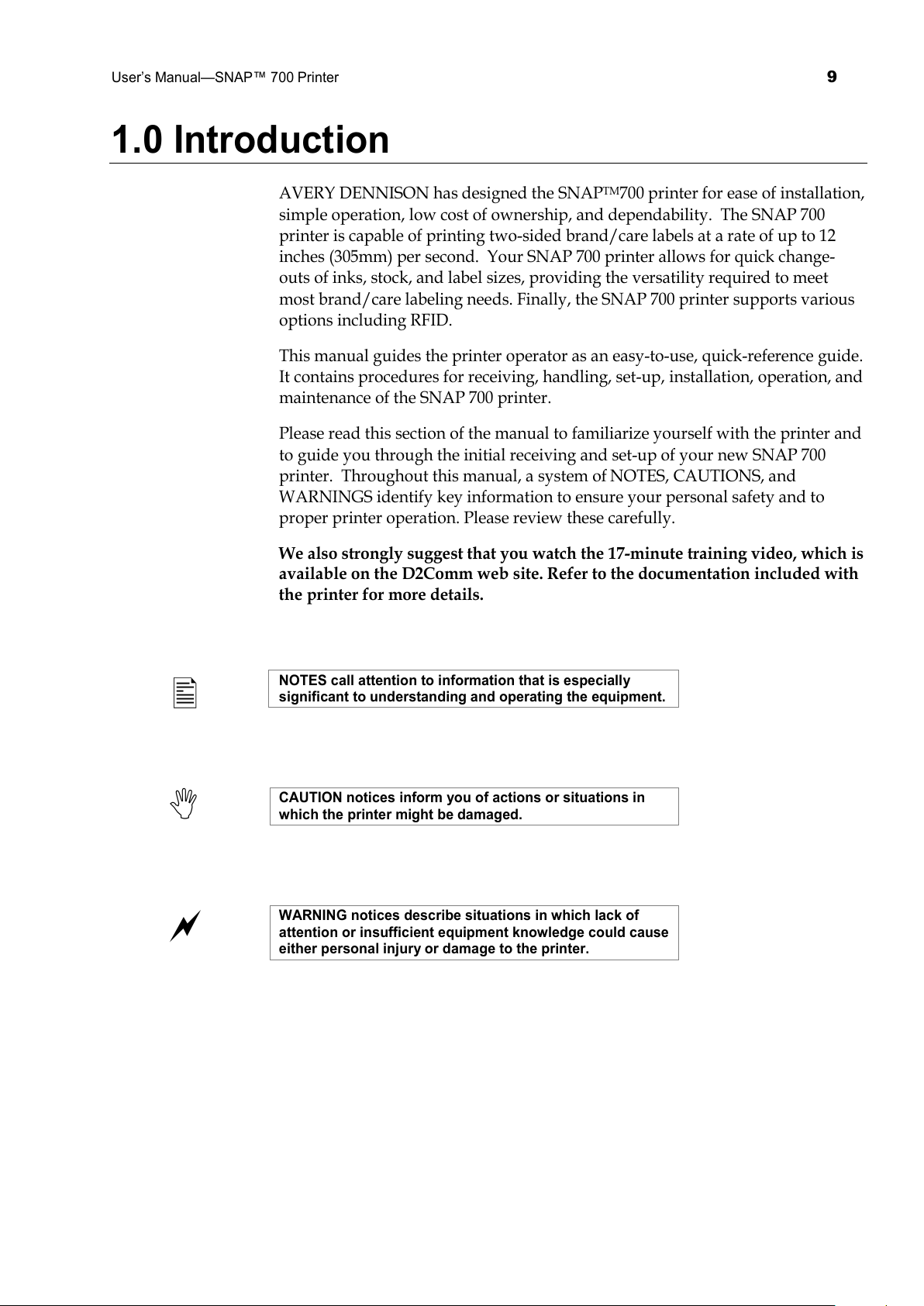
NOTES call attention to information that is especially
significant to understanding and operating the equipment.
CAUTION notices inform you of actions or situations in
which the printer might be damaged.
WARNING notices describe situations in which lack of
attention or insufficient equipment knowledge could cause
either personal injury or damage to the printer.
All manuals and user guides at all-guides.com

10
User’s Manual—SNAP™ 700 Printer
2.0 Installation
2.1 Preparing for the installation
2.1.1 AC Power Line
NOTE: AVERY DENNISON requires that the minimum
electrical service be 10 Amps @ 115VAC or 6 Amps @
230VAC. This will allow you to plug the SNAP 700 printer,
PC, and any additional support or service equipment into
the same service. We highly recommend that the printer
and its accessories be on a dedicated circuit.
The electrical service supplying power to the SNAP 700 printer or to peripheral
equipment connected to the SNAP 700 printer should meet standard electrical
code practices, including proper grounding and neutrals.
2.1.2 Location Considerations
The SNAP 700 printer weighs 60 pounds (27.2 Kg) and requires a table of
sufficient quality and strength to handle this load. The printer requires an area
of approximately 72" wide x 30" deep x 32" high (1.8 m x 76 cm x 81 cm). The
host PC (if used) and any printer options will increase the required area. AVERY
DENNISON recommends using an industrial type worktable. Refer to Figure 1
below.
The SNAP 700 printer is designed for easy operator accessibility to the printer
controls and components. Select your SNAP 700 printer’s location to meet the
following criteria:
1. Physical demands on the operator will dictate proper height of the table
supporting the printer. Ensure the operator has comfortable access to the
printer. Refer to Figure 1.
2. Allow enough space for smooth flow of materials that the operator will
load on the printer as well as space for processing the finished product
from the printer.
3. While AVERY DENNISON has designed the printer to be reasonably
quiet, select an area where repetitious noise from printing and cutting
processes is acceptable.
CAUTION: Each customer must take responsibility to
ensure the workstation created for the SNAP 500 printer
meets the recommended requirements to ensure optimal
operation of the printer.
All manuals and user guides at all-guides.com

User’s Manual—SNAP™ 700 Printer
11
Figure 1. Recommended Workstation Layout
2.1.3 PC Requirements
Most customers use a personal computer to download information to the SNAP
500 printer. The printer can be connected to any type of computer capable of
sending the AVERY DENNISON Command Language, or PCL.
PCMate Platinum tag and label printing software supports the new virtual
control panel feature when using the SNAP 500 printer. PCMate features higher
communication speeds of the SNAP 500. Finally, it can deliver firmware
upgrades from the Internet.
NOTE: PCMate Platinum requires the following minimum
system:
• IBM ® PC or Compatible
• Microsoft Windows® 2000, XP, 7 or later (check for latest version of
Windows)
• At least 256 Megabytes of RAM
• At least 4 Gigabyte of available disk space
• Pentium III or later processor, 800Mhz
• Monitor with 1024 x 768 resolution
• CD ROM drive
• Internet Connection to access software upgrades and remote diagnostics
Refer to your PCMate Platinum user’s manual for proper installation procedures.
All manuals and user guides at all-guides.com
all-guides.com

12
User’s Manual—SNAP™ 700 Printer
2.1.4 User Safety
1. Follow all of the safety requirements and procedures established for your
facility.
2. Turn off the power to the printer before cleaning, servicing, or replacing
any components.
3. You do not have to turn off the power when loading or changing
supplies.
CAUTION: The SNAP 700 printer has some pinch points
which have safeguards design in. AVERY DENNISION
strongly recommends that you do not modify or bypass
these safeguards.
CAUTION: Danger of explosion id battery is incorrectly
replaced. Return product to Avery Dennison for proper
replacement and disposal. Call 1 – 800 – 543 – 6650
Warning:
There are hazardous moving parts at the
print head station
. Keep hair, loose garments, jewelry
and fingers away.
2.2 Receiving
The SNAP 700 printer’s-shipping carton weighs 90 pounds (40.8 Kg The carton is
large and specially made to protect the printer. It may be awkward or difficult to
move by hand to its installation location.
CAUTION: Do not remove the printer from the carton or
unpack in the shipping / receiving department. Move the
carton to the installation location.
1. Move the SNAP 700 printers with a forklift, fork cart or handcart to its
intended location. It is easier and safer to use one of these handling
devices to move the printer. Leaving the printer in the carton while it is
being moved within your facility will help protect it until placed in its
new location.
2. The stacker and any other accessories purchased for the printer may be
shipped separately.
All manuals and user guides at all-guides.com

User’s Manual—SNAP™ 700 Printer
13
2.3 Unpacking
2.3.1 Removing the printer from the carton
1. Open the carton from the top by removing the banding straps and/or cutting
the taped seam on the top of the carton.
2. Remove top foam-packing layer (see Figure 2A).
Figure 2A – Shipping Carton
CAUTION: Do not discard any of the packing / shipping
material in case you have to move the printer to another
location or return it to AVERY DENNISON for service.
3. The printer has been wrapped with shrink wrap to protect the printer from
the packing material and moisture.
4. It requires 2 people to remove the printer from the carton.
5. Position your hands in the cardboard cutout as above. Carefully lift it out of
the box. Lift the printer from the bottom out of the lower foam packing and
place the printer on the workstation table.
6. Carefully remove the shrink wrap to avoid damaging the printer.
7. Turn the Stock Arbor knob counter-clockwise and remove the protective
foam behind the Stock Arbor.
8. Unpack the stacker from its box and place it on the workstation table next to
the printer. Refer to Section 2.5.1, Attaching the Stacker.
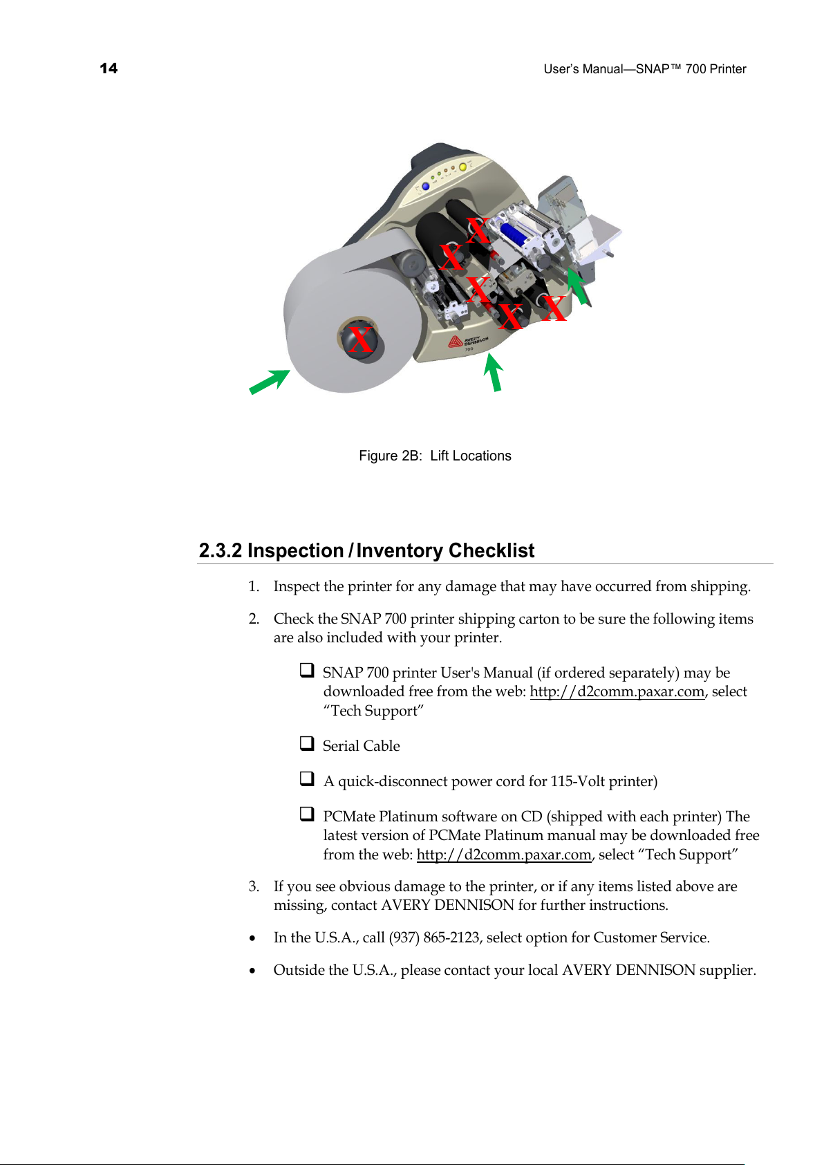
CAUTION: Lifting the printer from any component other
than case or stacker supports can damage the printer and
cause needless start up delays.
All manuals and user guides at all-guides.com
14
User’s Manual—SNAP™ 700 Printer
Figure 2B: Lift Locations
2.3.2 Inspection / Inventory Checklist
1. Inspect the printer for any damage that may have occurred from shipping.
2. Check the SNAP 700 printer shipping carton to be sure the following items
are also included with your printer.
SNAP 700 printer User's Manual (if ordered separately) may be
downloaded free from the web: http://d2comm.paxar.com, select
“Tech Support”
Serial Cable
A quick-disconnect power cord for 115-Volt printer)
PCMate Platinum software on CD (shipped with each printer) The
latest version of PCMate Platinum manual may be downloaded free
from the web: http://d2comm.paxar.com, select “Tech Support”
3. If you see obvious damage to the printer, or if any items listed above are
missing, contact AVERY DENNISON for further instructions.
• In the U.S.A., call (937) 865-2123, select option for Customer Service.
• Outside the U.S.A., please contact your local AVERY DENNISON supplier.
X
X
X
X
X
X
All manuals and user guides at all-guides.com

User’s Manual—SNAP™ 700 Printer
15
2.4 Printer Description
Shown below are the important parts of the SNAP 700 Printer. Please take a
moment to familiarize yourself with the printer.
Figure 3. SNAP 700 Printer
NOTE: Please take some time to become familiar with the
printer’s major components and their functions. Refer to
Figure 3.
• The Stock Unwind Arbor holds the supply roll. By rotating the outer knob
clockwise or counterclockwise, you can adjust the Arbor to accommodate
stocks ranging from ½ inch - 5 inches (12.7 mm - 127 mm) wide. The arbor
auto-centers the stock through the printer. Metal fingers extend to hold the
supply roll in place. This allows back tension which keeps the stock centered
through the printer.
• The Stock (Web) Guide guides the stock through the printer and is adjusted
by rotating the black knob.
• The Upper and Lower Print Stations house the print head assemblies. They
have knobs for adjusting print head pressure and print density to control the
print quality.
Upper Ink Arbors
Control Panel
Upper Print Station
Rotary Knife
Stacker
Lower Ink Arbors
Lower Print Station
Stock (Web) Guide
Stock Arbor
All manuals and user guides at all-guides.com

16
User’s Manual—SNAP™ 700 Printer
• The Upper and Lower Ink Arbors are adjusted using the black knob on the
end of the arbor. To open up and close down the self center arbor to the ink
cores rotate the knob. Do not over tighten onto the core to hole them in
place. They accommodate ink rolls ranging from 1 inch (25mm) to 5 inches
(127 mm) cores.
• A Rotary Knife Assembly comes with printer. When printing woven tapes,
use a Sonic Knife accessory option that provides ultrasonic cutting and
sealing.
• The Stacker collects the finished, printed labels. You can adjust it to
accommodate a variety of label stocks and short or long labels. Once the
stacker reaches the bottom, the printer will stop, indicate the stacker is full,
and allow you to remove the labels.
• The Control Panel with buttons and LED’s indicate printer status and
information about specific jobs.
WARNING: This is a class A product. In a domestic environment
this product may cause radio interference in which case the user
may be required to take adequate measures.
All manuals and user guides at all-guides.com
all-guides.com

User’s Manual—SNAP™ 700 Printer
17
2.5 Setting up the Printer
2.5.1 Attaching the Stacker
Figure 4. Rotary Knife and Stacker
The stacker and knife are two separate assemblies that can be installed and/or
replaced easily and quickly. For information on adjusting the stacker, refer to
Section 4.2.
1. Locate the two shafts on the printer below the Auxiliary Feed and Knife
assembly (see Figure 4).
2. Slide the stacker onto the two shafts until the backside of the stacker is
beyond the stock size to be run.
NOTE: Be sure to slide the top of the stacker behind the
Nip Roller stripping plate.
3. With the power off, connect the stacker cable extending from the bottom of
the stacker assembly into the larger connector on the right side of the printer.
Rotating the connector and applying light pressure inward will help engage
the connectors.
NOTE: There is a sleeve on the connector that will snap
when the connector is fully engaged with the mating
connector. The two cables will slide into each other only
when the connectors are properly aligned with each other.
Platform
Stacker Sensor
Switch
Label Stop
Rotary Knife
Assembly
Shafts
Nip Roller
All manuals and user guides at all-guides.com
18
User’s Manual—SNAP™ 700 Printer
2.5.2 Checking the Main Fuse Configuration
WARNING: Before powering on the printer, you must
check to be sure the main fuses on the AC power
receptacle are set for the appropriate voltage for your
location (Line voltage of 90-132VAC @ 50-60Hz, single
phase or 180-265VAC @ 50-60Hz, single phase).
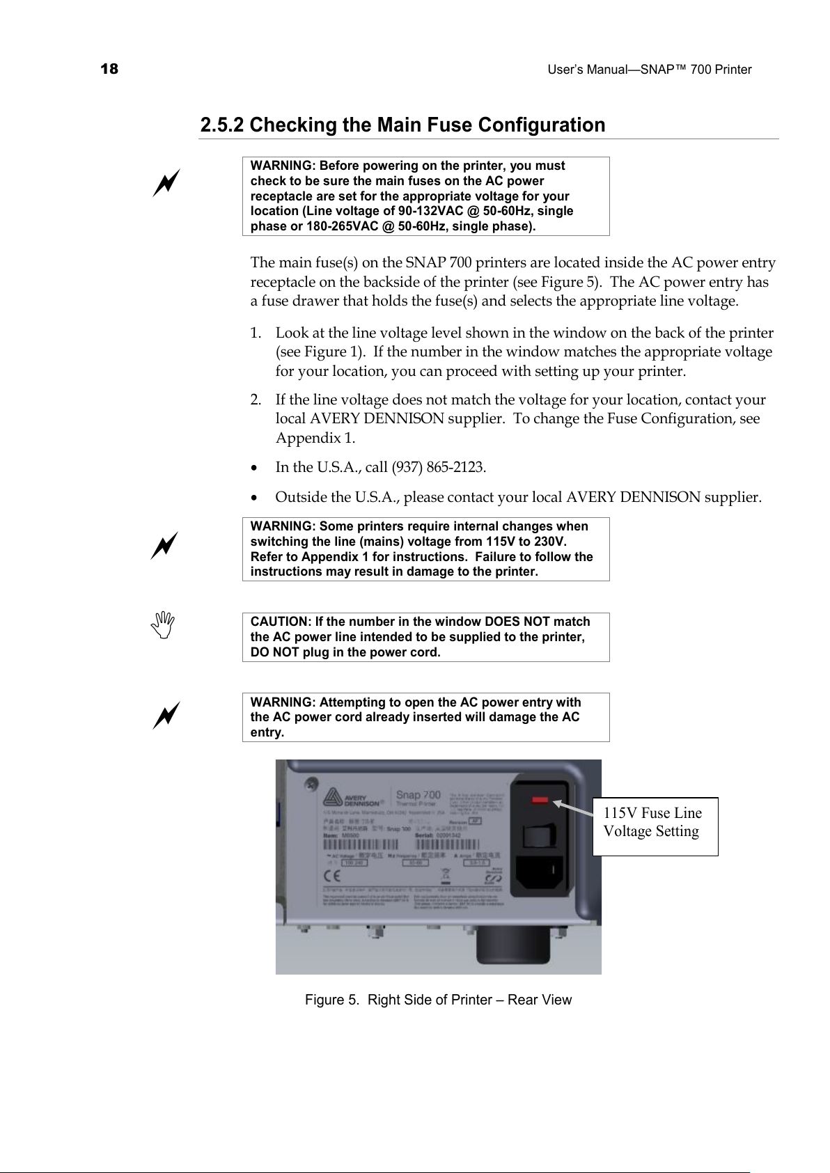
The main fuse(s) on the SNAP 700 printers are located inside the AC power entry
receptacle on the backside of the printer (see Figure 5). The AC power entry has
a fuse drawer that holds the fuse(s) and selects the appropriate line voltage.
1. Look at the line voltage level shown in the window on the back of the printer
(see Figure 1). If the number in the window matches the appropriate voltage
for your location, you can proceed with setting up your printer.
2. If the line voltage does not match the voltage for your location, contact your
local AVERY DENNISON supplier. To change the Fuse Configuration, see
Appendix 1.
• In the U.S.A., call (937) 865-2123.
• Outside the U.S.A., please contact your local AVERY DENNISON supplier.
WARNING: Some printers require internal changes when
switching the line (mains) voltage from 115V to 230V.
Refer to Appendix 1 for instructions. Failure to follow the
instructions may result in damage to the printer.
CAUTION: If the number in the window DOES NOT match
the AC power line intended to be supplied to the printer,
DO NOT plug in the power cord.
WARNING: Attempting to open the AC power entry with
the AC power cord already inserted will damage the AC
entry.
Figure 5. Right Side of Printer – Rear View
115V Fuse Line
Voltage Setting
All manuals and user guides at all-guides.com
User’s Manual—SNAP™ 700 Printer
19
2.5.3 Installing the Power Cord
A quick-disconnect power cord is shipped with each 115V printer. The cord for
115V printers will use the standard three-prong plug used in the U.S.A.
If a power cord is not supplied with your printer, and your printer is operating at
a rating other than 115V, you will need to obtain a power cord for your voltage
application. The power cord should have an IEC-320-C13 plug on one end and
the appropriate plug for your power receptacle at the other end.
1. Locate the AC power entry receptacle on the backside of the printer just
below the power switch (see Figure 5).
2. Plug the power cord into the AC power entry receptacle.
2.5.4 Installing the PC Interface Cable
If you will be using your SNAP 700 printers with a personal computer, one of the
following computer interface cables is required:
• Null-modem serial cable with Part number 581139 connector
• USB / Serial adapter – Part number 581140
• Ethernet adapter – Part number 05591105
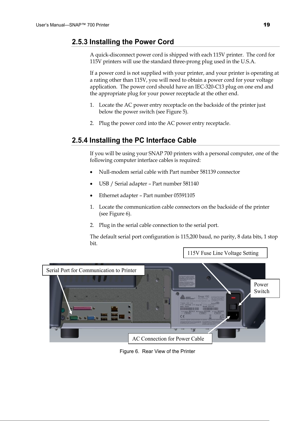
1. Locate the communication cable connectors on the backside of the printer
(see Figure 6).
2. Plug in the serial cable connection to the serial port.
The default serial port configuration is 115,200 baud, no parity, 8 data bits, 1 stop
bit.
Figure 6. Rear View of the Printer
115V Fuse Line Voltage Setting
Power
Switch
AC Connection for Power Cable
Serial Port for Communication to Printer
All manuals and user guides at all-guides.com
20
User’s Manual—SNAP™ 700 Printer
2.5.5 Installing PCMate Platinum Software
The software used to drive the AVERY DENNISON family of printers is covered
in a separate manual. The PCMate Platinum software is a Windows® application
used to create formats for the SNAP 700 printer as well as all other AVERY
DENNISON control printers.
The printer is also capable of operating directly from a mainframe when using
the RS232 interface and AVERY DENNISON's command language (PCL).
2.6 Printing a Test Label
2.6.1 Loading Supplies
Before you can print a test label, the printer must be loaded with stock and ink.
Refer to section 3.1 for instructions on loading the stock and ink.
2.6.2 Turning the Printer on
1. Turn the power switch on. The power switch is located on the back of the
printer, just above the power cord.
2. The four lights on the Printer Control Panel will come on for a few seconds, and
then all four lights will start to flash. This indicates that the printer is performing
its internal diagnostic tests. After several seconds, the lights will stop flashing
and the Ready light will come on. This indicates that the printer is ready.
NOTE: During the power sequence the knife will cycle
backwards 1 time to find home and there will be an audible
bell as the printer powers up.
3. If any problems occur, see sections 10 and 11, Troubleshooting.
2.6.2 Selecting the Test Format
There are two test formats built into the printer. These are selected using the
Option Menu System. The steps below describe how to select one of the test
formats. For more information on the Option Menu System, see section 3.4.
When the instructions say to press a button, press the
button for a short time and release it. When the
instructions say to press and hold a button, press the
button and hold it down until the printer responds.
When you are in the Option Menu System, you can get out
by pressing and holding the Voice button until the printer
says “Returning to print mode.”
1. Press and hold the Voice button until the printer says “Press Start for Test
All manuals and user guides at all-guides.com
User’s Manual—SNAP™ 700 Printer
21
Patterns.”
2. Press the Start button. The printer will say “Press Start for Test Pattern 1.” If
you want to print test pattern 1, press the Start Button, then go to step 3. If you
want to print test pattern 2, press the Voice button. The printer will say “Press
Start for Test Pattern 2.” Press the Start button.
3. The printer will say “Ready to print test pattern 1 (or 2), Returning to print
mode.” At this time the Data light will come on. The printer is now ready to
print the test labels.
2.6.3 Printing the Test Labels
1. Press the Start button. The stacker (if installed) will move the platform to its
start position and the printer will begin printing the test labels. If there is no
stacker installed there will be a noticeable delay in the start of the printer.
2. If any problems occur, either the Supply or Error light will come on. If this
happens, press the Voice button and the printer will say a message telling what
the problem is. Correct the problem and press the Start button again. Repeat
this until the printer runs continuously.
3. If you can’t get the printer to run, refer to sections 10 and 11 Troubleshooting.
All manuals and user guides at all-guides.com
all-guides.com
22
User’s Manual—SNAP™ 700 Printer
3.0 Operation
3.1 Loading Supplies
Your SNAP 700 printer is designed with upper and optional lower ink supply
stations. . The ink supply station setup is dictated by the option of the printer
your ordered. There is no way to change this setup at your location.
The ink arbors have a self-center guide to locate the roll of ink to ensure smooth
tracking through the machine.
The ink cores have splines on their inside surfaces. These splines align with the
grooves in the ink arbors. Splines allow the printer to control the tension of the
ink ribbon during printing, minimizing wrinkling and optimizing print quality.
NOTE: Only use the white plastic cores on the SNAP
printers. If you have a black plastic core they are design
for the Avery Dennison 9800 series printers.
3.1.1 Installing Ink to the Top Ink Supply Station
1. Install an empty ink core on the upper ink rewind arbor. It is important that
the core be the same width or wider as the core of the ink being used.
NOTE: The empty ink core should be the same width as
the ink supply roll.
a. Rotate the core slightly to align the splines and grooves on the arbor.
Slide it gently onto the arbor until it contacts the back core stop.
b. If the front core locator is not exposed turn the black knob on the end
of the arbor counterclockwise to bring it past the end of the core. To
clamp the core rotate the black knob clockwise to center the core on
the arbor. See Figure 7.
CAUTION: Do Not over tighten the core locators. Little to
no pressure is needed to keep the core centered. Over
tightening can damage the plastic stops.
CAUTION: To avoid damaging the print head, the ink
supply roll should be ¼ inch (6 mm) wider than the stock.
All manuals and user guides at all-guides.com

User’s Manual—SNAP™ 700 Printer
23
Figure 7. Upper Ink Supply and Print Stations - Unloaded
NOTE: The ink system is designed to rewind one roll of ink
at a time. When the rewind core is full, replace it with an
empty ink core. Do not try to add a second roll to the first
rewind core, since it will not track through the printer
correctly and will result in poor print quality.
2. Remove the plastic packaging around the roll of ink and install it on the ink
supply arbor. Ensure that the leading edge is pointing toward the Stock
Arbor.
NOTE: For best results, leave the ink roll wrapped in
plastic until you are ready to use it in the printer.
3. Open the print roller (See Figure 8).
4. Pull the ink down and to the right, beneath the turn bar, between the upper
print roller and the upper print station, toward the stacker side of the upper
ink rewind arbor.
Upper Ink
Rewind Arbor
Upper Ink
Supply Arbor
Core Stop Upper Print
Station
All manuals and user guides at all-guides.com
24
User’s Manual—SNAP™ 700 Printer
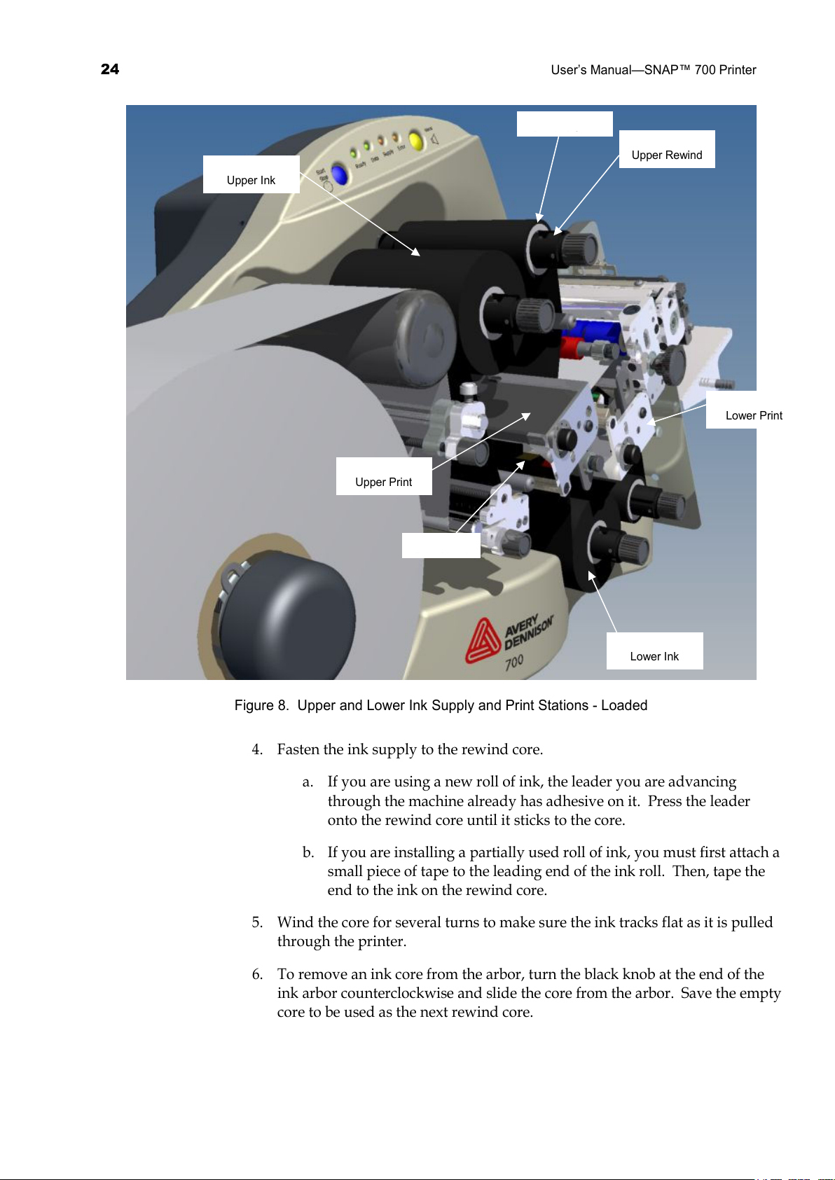
Figure 8. Upper and Lower Ink Supply and Print Stations - Loaded
4. Fasten the ink supply to the rewind core.
a. If you are using a new roll of ink, the leader you are advancing
through the machine already has adhesive on it. Press the leader
onto the rewind core until it sticks to the core.
b. If you are installing a partially used roll of ink, you must first attach a
small piece of tape to the leading end of the ink roll. Then, tape the
end to the ink on the rewind core.
5. Wind the core for several turns to make sure the ink tracks flat as it is pulled
through the printer.
6. To remove an ink core from the arbor, turn the black knob at the end of the
ink arbor counterclockwise and slide the core from the arbor. Save the empty
core to be used as the next rewind core.
Upper Rewind
Upper Ink
Upper Print
Lower Print
Lower Ink
All manuals and user guides at all-guides.com

User’s Manual—SNAP™ 700 Printer
25
Threading Diagram
Decurler & Web
Guide not used on
All manuals and user guides at all-guides.com
26
User’s Manual—SNAP™ 700 Printer
Threading Diagram - RFID
3.1.2 Installing Ink to the Bottom Ink Supply Station
Installing Ink on the Bottom Print Station is done in the same way as the Top
Print Station, except that the ink runs up over the Turn bar, across the print head
to the rewind arbor.
3.1.3 Loading the Stock
Before loading a roll of stock, you will need to be familiar with the following
parts of the SNAP 700 printer (Refer to Figures 9 and 10).
The Stock Arbor is designed to clamp the core of the stock supply rolls to hold
them in place during printing operations. This function provides back tension
which helps keep the stock straight while it moves to the center of the print head.
By rotating the stock arbor knob, you can adjust for roll widths ranging in size
from ½ inch to 5 inches (12.7 mm to 127 mm). This helps keep the stock straight
while it moves to the center of the print head. To function properly, the stock
roll must be wound firmly and centered on the core with no telescoping of the
roll. There are no other adjustments to the stock arbor.
The Stock (Web) Guide is located between the Stock Arbor and Sensor Module
Station to guides the stock through the machine toward the center of the print
head. The black knob located at the end of the web guide controls the width of
the guides. Turning the knob clockwise will widen the web guides, while
counterclockwise turns will narrow the web guides.
The Upper and Lower Print Stations on the SNAP 700 printer are stationary.
The rollers swing open and closed for threading and printing. These rollers are
held in position for printing with latches on both the inside and outside end of
the rollers.
NOTE: If you are printing two-sided labels, both print
rollers must be closed in order for the printer to operate.
If a two-sided label design is sent to the printer and the
lower print roller is open, the Error LED will light up and
the printer will stop. If you are printing single-sided
labels, the lower print roller should remain open so the ink
rolls will not rotate.
The Stock Feed is the assembly located in front of the knife. The Feed has a knob,
which is used to manually advance the material through the knife, the nip roller,
and into the stacker. (See figure 10)
New rolls of Supply Stock are sealed and packaged individually. When you are
ready to load the stock, remove the packaging and follow the steps below.
1. Remove the tape holding the end of the supply stock to the outer part of the
All manuals and user guides at all-guides.com
all-guides.com
User’s Manual—SNAP™ 700 Printer
27
roll. To avoid damaging the rollers or print heads, use scissors to cut off any
portion of the supply stock that has adhesive on it.
2. Rotate the unwind knob clockwise to retract the “fingers”. Open the
assembly so the back locator hub and front locking fingers are wider that the
material.
3. To install the stock supply roll, begin with the leading end at the top of the
roll pulling off towards the stacker.
4. Slide the stock roll onto the Stock Arbor (see Figure 9).
5. Rotate the Stock Arbor knob counter-clockwise quickly to extend the fingers
that hold the supply roll in place.
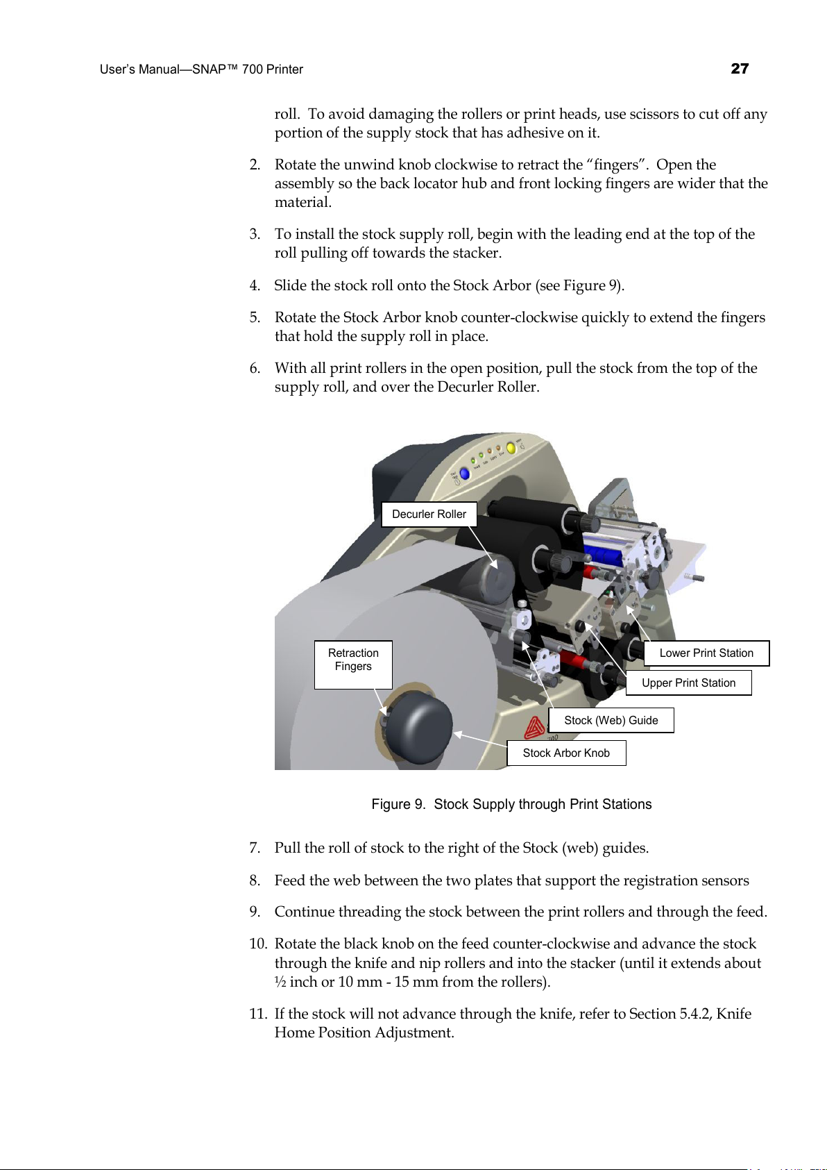
6. With all print rollers in the open position, pull the stock from the top of the
supply roll, and over the Decurler Roller.
Figure 9. Stock Supply through Print Stations
7. Pull the roll of stock to the right of the Stock (web) guides.
8. Feed the web between the two plates that support the registration sensors
9. Continue threading the stock between the print rollers and through the feed.
10. Rotate the black knob on the feed counter-clockwise and advance the stock
through the knife and nip rollers and into the stacker (until it extends about
½ inch or 10 mm - 15 mm from the rollers).
11. If the stock will not advance through the knife, refer to Section 5.4.2, Knife
Home Position Adjustment.
Decurler Roller
Stock Arbor Knob
Retraction
Fingers
Stock (Web) Guide
Upper Print Station
Lower Print Station
All manuals and user guides at all-guides.com

28
User’s Manual—SNAP™ 700 Printer
12. Rotate the stock web guide knob to align it to the stock width.
13. Close the upper and lower print rollers.
Figure 10. Stock Supply Through Knife and Stacker
3.1.4 Butt Splice
CAUTION: To prevent damage to the print head, do not
use butt splices.
The SNAP 700 printer is designed to allow for fast, frequent changing and
loading of stock and ink. We recommend re-threading the stock rather than to
using a butt splice. If you determine that splicing is faster for threading, tape the
ends of the stock together. Turn the feed roller and advance the splice through
the printer. Do not try and run the splice through the printer as it can cause
damage.
3.2 Sending a Print Job to the Printer
In order to print labels, you must send a print Job to the printer. The print job
tells the printer what label to print, what information to print on the label, and
how many labels to print.
Getting a print job to the printer depends on how your company system is set
up. You may be using AVERY DENNISON’s label design program PCMate
Stock Web
Guide Knob
Upper Print
Roller
Lower Print
Roller
Stacker
Knife
Feed Roller
All manuals and user guides at all-guides.com
User’s Manual—SNAP™ 700 Printer
29
Platinum, or you may be using a special application on a PC or a mainframe.
Consult your supervisor on how your company sends print jobs.
3.3 Printing Labels
3.3.1 The Control Panel
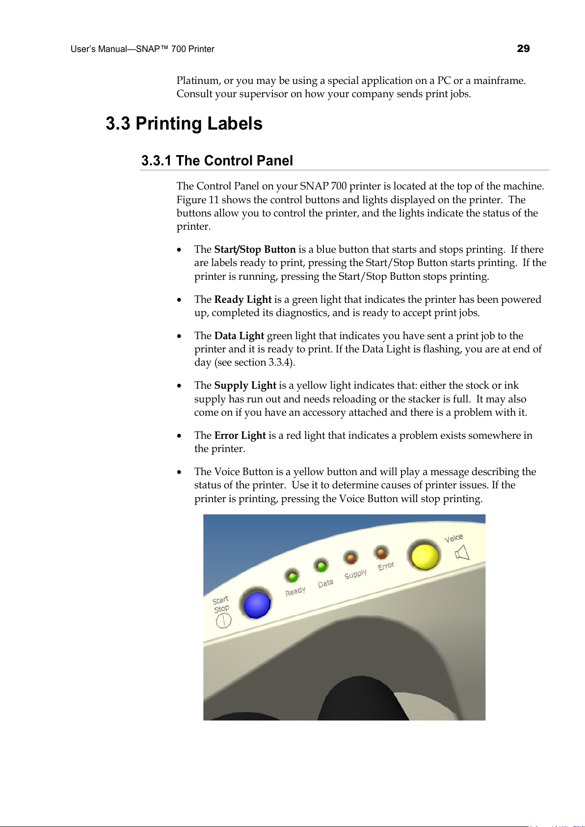
The Control Panel on your SNAP 700 printer is located at the top of the machine.
Figure 11 shows the control buttons and lights displayed on the printer. The
buttons allow you to control the printer, and the lights indicate the status of the
printer.
• The Start/Stop Button is a blue button that starts and stops printing. If there
are labels ready to print, pressing the Start/Stop Button starts printing. If the
printer is running, pressing the Start/Stop Button stops printing.
• The Ready Light is a green light that indicates the printer has been powered
up, completed its diagnostics, and is ready to accept print jobs.
• The Data Light green light that indicates you have sent a print job to the
printer and it is ready to print. If the Data Light is flashing, you are at end of
day (see section 3.3.4).
• The Supply Light is a yellow light indicates that: either the stock or ink
supply has run out and needs reloading or the stacker is full. It may also
come on if you have an accessory attached and there is a problem with it.
• The Error Light is a red light that indicates a problem exists somewhere in
the printer.
• The Voice Button is a yellow button and will play a message describing the
status of the printer. Use it to determine causes of printer issues. If the
printer is printing, pressing the Voice Button will stop printing.
All manuals and user guides at all-guides.com
30
User’s Manual—SNAP™ 700 Printer
Figure 11. Control Panel
3.3.2 Printing
Once a print job has been sent to the printer, the Data light will come on. You
can then press the Start/Stop Button to start printing.
When printing starts, the stacker will move the platform to the correct position.
Then the printer will start printing labels.
As the printer prints, the cut labels will drop onto the top of the stack. As the
stack grows, the stacker platform moves down so that the top of the stack stays
in the same position.
3.3.2.1 Handling the Leader
When you start printing for the first time, or after some errors, the printer will
create a leader. The leader is a longer piece of material that may be blank or may
have some partially printed labels. These labels are not usable and are not part
of the print job.
When the printer creates a leader, grab it as it comes out of the nip rollers and
pull it out of the stacker when the printer does the first cut. (If you are not using
the stacker, or you are using some other accessory such as a Rewinder or Looper,
you may need to handle the leader differently.)
3.3.3 Errors
If the printer encounters a problem during printing, it will stop printing and
either the Supply or Error light will come on. The Supply light means that there
is a problem with either the ink or the stock, or the stacker is full. The error light
means that there is some other problem with the printer.
There are three ways to determine what the problem is:
1. Press the Voice button. A message will play that describes the problem.
2. The problem will be displayed in the Printer Status box on the Virtual
Control Panel in PCMate Platinum. See section 8.0 for a description of the
Virtual Control Panel.
Correct the problem and press the Start Button to start printing again.
NOTE: If the error condition no longer exists, the printer
will start. It is not necessary to press the Start button
twice as is required with previous AVERY DENNISON
printer models. If the error continues to recur, contact
your local AVERY DENNISON representative.
All manuals and user guides at all-guides.com
 Loading...