

Page 1
User’s Manual
SNAP
TM
500
Printer
AVERY DENNISON
Manual Edition 5.3.1
17 June 2013
Manual Part Number 581398
All manuals and user guides at all-guides.com
all-guides.com
Page 2
User’s Manual—SNAP™ 500 Printer
Manual Part Number 581398
WARNING
This device complies with Part 15 of the FCC Rules. Operation is subject to the
following two conditions:
1) this device may not cause harmful interference, and
2) this device must accept any interference that may cause undesired operations.
This Class A digital apparatus meets all requirements of the Canadian Interference
Causing Equipment Regulations. Cet appareil numerique de la classe A respecte
toutes les exigences du Reglement sur le material broilleur du Canada
All manuals and user guides at all-guides.com
Page 3

All manuals and user guides at all-guides.com
Page 4
User’s Manual—SNAP™ 500 Printer
Table of Contents
1.0 INTRODUCTION 9
2.0 INSTALLATION 10
2.1 Preparing for the installation 10
2.1.1 AC Power Line 10
2.1.2 Location Considerations 10
2.1.3 Personal Computer Requirements 11
2.1.4 User Safety 12
2.2 Receiving 12
2.3 Unpacking 12
2.3.1 Removing the printer from the carton 12
2.3.2 Inspection / Inventory Checklist 13
2.4 Printer Description 14
2.5 Setting Up the Printer 16
2.5.1 Attaching the Stacker 16
2.5.2 Checking the Main Fuse Configuration 17
2.5.3 Installing the Power Cord 18
2.5.4 Installing the PC Interface Cable 18
2.5.5 Installing PCMate Platinum Software 20
2.6 Printing a Test Label 20
2.6.1 Loading Supplies 20
2.6.2 Turning the Printer on 20
2.6.2 Selecting the Test Format 20
2.6.3 Printing the Test Labels 21
3.0 OPERATION 22
3.1 Loading Supplies 22
3.1.1 Installing Ink to the Top Ink Supply Station 22
3.1.2 Installing Ink to the Bottom Ink Supply Station 25
3.1.3 Loading the Tape 25
3.1.4 Butt Splice 27
3.2 Sending a Print Job to the Printer 27
3.3 Printing Labels 28
3.3.1 The Control Panel 28
3.3.2 Printing 29
3.3.2.1 Handling the Leader 29
All manuals and user guides at all-guides.com
Page 5

User’s Manual—SNAP™ 500 Printer
3.3.3 Errors 29
3.3.4 End of Day 30
3.3.5 Clearing Print Jobs 30
3.3.6 Using Pre-Printed Tape 30
3.3.6.1 Selecting the Sensor 31
3.3.6.2 Aligning the Tape to the Sensor 31
3.3.7 Feeding the tape 31
3.4 Option Menu System 31
3.4.1 Running Test Labels 32
3.4.2 Using Voice Demos 35
3.4.3 Setting / Adjusting Voice Button Volume 36
4.0 MAKING ADJUSTMENTS 38
4.1 Print Head Adjustments 38
4.1.1 Adjusting Print Head Pressure 38
4.1.2 Adjusting Density (Darkness) 39
4.2 Adjusting the Stacker 39
4.2.1 Stacker Position 40
4.2.2 Toggle Switch 40
4.2.3 Stacker Angle 40
4.2.4 Platform 41
4.3 Print and Cut Adjustments 42
4.3.1 Cut Adjust 42
4.3.2 Print Adjust 43
4.4 Printer Features 43
4.4.1 Selecting the Printer Language 43
4.4.2 Setting the Date and Time 44
4.4.3 Enabling or Disabling the Cutter 44
4.4.4 Selecting the Print Speed 44
4.4.5 Selecting the Flagging Mode 45
4.4.6 Selecting the Sense Mark Type 45
4.4.7 Setting the Default Transfer Type 46
4.4.8 Viewing the Life Counts 46
5.0 MAINTENANCE 47
5.1 Print Head Cleaning and Handling 47
5.1.1 Handling Techniques 47
5.1.2 Cleaning Procedures 48
5.2 Print Head Replacement 49
5.3 Lubrication 51
All manuals and user guides at all-guides.com
Page 6
User’s Manual—SNAP™ 500 Printer
5.4 Rotary Knife Assembly 51
5.4.1 Removing and Replacing the Knife Assembly 52
5.4.2 Adjust the Knife Home Position 53
6.0 SERVICE ADJUSTMENTS 54
6.1 Tape (Web) Guide Position 54
6.2 Tape (Web) Guide Width Adjustments 54
6.3 Auxiliary Feed 54
6.4 Knife Shear Adjustment 54
7.0 REMOTE CONTROL / DISPLAY MODULE 56
7.1 Controlling the Printer 57
7.2 The Menu System 57
7.3 Changing Values 57
8.0 VIRTUAL CONTROL PANEL 59
8.1 Viewing and Changing Printer Settings 60
9.0 UPGRADING THE PRINTER SOFTWARE 61
9.1 Introduction 61
9.2 What is Needed 61
9.3 Getting the UPG file 61
9.3.1 Using SpecStar to get the UPG file 61
9.3.2 Ordering the UPG file on CD 61
9.4 Getting Ready to Upgrade the Printer 61
9.5 Performing the Upgrade 61
10.0 ELECTRICAL TROUBLESHOOTING 65
10.1 Power Up / Sign On / Communications 65
10.2 Tape / Ink Advance 67
10.3 Print 68
10.4 Cut / Stack 70
10.5 Printer Errors 71
11.0 MECHANICAL TROUBLESHOOTING 75
11.1 Tape 75
All manuals and user guides at all-guides.com
all-guides.com
Page 7

User’s Manual—SNAP™ 500 Printer
11.2 Ink 76
11.3 Print 76
11.4 Knife 76
APPENDICES 77
1. Fuse Configuration 77
1.2 Reconfiguring the Internal Power Supply 78
2. Ink and Tape Transfer Types 80
3. Printer Specifications 82
4. Instructions for Factory / Field Installation of Back Reflective Sensor 580010 84
Installation Procedure 84
Sensor Installation 86
Final Assembly 87
Back Reflective Sensor Mount Assembly Drawing 87
5. Instructions for Factory / Field Installation of Top Sensor Assemblies 580009 & 580011
88
Installation Procedure, Front of Printer 88
Installation Procedure, Rear Assembly 92
Final Assembly 94
Contrast Sensor Assembly Drawing 95
6. Instructions for Factory / Field Installation of High Speed Verifier Assembly 580015 96
Installation Procedure - Mechanical 96
Installation Procedure – Electrical 98
Installation – Rear Cover 99
7. Programming the Contrast Sensors 101
Programming the 580011 Contrast Sensor 101
Programming the 580009 Contrast Sensor 102
8. Warranty Information 104
Limited Warranty Error! Bookmark not defined.
Parts Error! Bookmark not defined.
Service Error! Bookmark not defined.
9. Option Menu System Flowchart 107
ELECTRICAL ASSEMBLY DRAWINGS 109
Electrical System Schematic 110
Harness Connections 111
All manuals and user guides at all-guides.com
Page 8

User’s Manual—SNAP™ 500 Printer
MECHANICAL ASSEMBLY DRAWINGS 113
Unwind Assembly Drawing 114
Unwind Parts List 115
Web Guide Assembly Drawing 116
Web Guide Parts List 117
Printhead Assembly Drawing 118
Printhead Parts List 119
Ink Unwind / Rewind Assembly Drawing 120
Ink Unwind / Rewind Parts List 121
Upright Frame Assembly Drawing 122
Upright Frame Parts List 123
Covers Assembly Drawing 124
Covers Parts List 125
Feed – Drive Train Assembly Drawing 126
Feed – Drive Train Parts List 127
Knife – Drive – Nip Roller Assembly Drawing 128
Knife – Drive – Nip Roller Parts List 129
Rewind Assembly Drawing (Option) 130
Rewind Parts List (Option) 131
All manuals and user guides at all-guides.com
Page 9
User’s Manual—SNAP™ 500 Printer
9
1.0 Introduction
The AVERY DENNISON SNAP 500 printer is designed for convenience, easy
installation and operation, and dependability. It is capable of printing two-sided
brand/care labels at a rate of up to 7 inches (178 mm) per second. Your AVERY
DENNISON SNAP 500 printer allows for quick change-outs of inks, tape, and
label sizes, providing the versatility required to meet most brand/care labeling
needs.
This manual is prepared for the actual printer operator, and is intended to be an
easy-to-use, quick reference guide. It contains procedures for receiving,
handling, set-up, installation, operation, and maintenance of the AVERY
DENNISON SNAP 500 printer.
Please read this section of the manual to familiarize yourself with the printer and
to guide you through the initial receiving and set-up of your new AVERY
DENNISON SNAP 500 printer. Throughout this manual, a system of NOTES,
CAUTIONS, and WARNINGS has been used to quickly identify key information
you need to help ensure your personal safety and to operate the printer properly.
Before you install or use your new AVERY DENNISON SNAP 500 printer, it is
important to review all NOTES, CAUTIONS, and WARNINGS in this manual to
help ensure maximum benefit from your printer. We also strongly suggest that
you watch the 17-minute training video, which will operate in any CD-ROM
drive. You may want to keep the training video with this manual for easy, quick
reference in the future.
NOTES call attention to information that is especially
significant to understanding and operating the equipment.
CAUTION notices inform you of actions or situations in
which the printer might be damaged.
WARNING notices describe situations in which lack of
attention or insufficient equipment knowledge could cause
either personal injury or damage to the printer.
All manuals and user guides at all-guides.com
Page 10
10
User’s Manual—SNAP™ 500 Printer
2.0 Installation
2.1 Preparing for the installation
2.1.1 AC Power Line
NOTE: AVERY DENNISON requires that the minimum
electrical service be 10 Amps @ 115VAC or 6 Amps @
230VAC. This will allow the AVERY DENNISON SNAP 500
printer, PC, and any additional support or service
equipment to be plugged into the same service. It is
highly recommended that the printer and its accessories
be on a dedicated circuit.
The electrical service supplying power to the AVERY DENNISON SNAP 500
printer or to peripheral equipment connected to the AVERY DENNISON SNAP
500 printer should meet standard electrical code practices, including proper
grounding and neutrals.
2.1.2 Location Considerations
The printer weighs 45 pounds (20.5 Kg) and requires a table of sufficient quality
and strength to handle this load. The AVERY DENNISON SNAP 500 printer
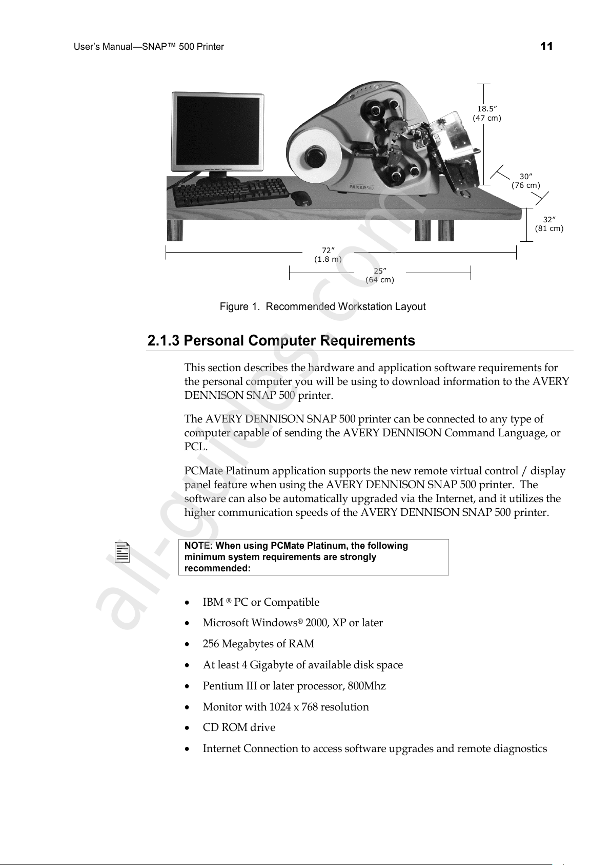
requires an area with the approximate dimensions of 72" wide x 30" deep x 32"
high (1.8 m x 76 cm x 81 cm). The host PC (if used) and any printer options will
increase the required area. AVERY DENNISON recommends using an industrial
type worktable. Refer to Figure 1 below.
The AVERY DENNISON SNAP 500 printer is designed for easy operator
accessibility to the printer controls and components. Select your AVERY
DENNISON SNAP 500 printer’s location to meet the following criteria:
1. Choose an area that maintains optimum flow of your product and allows for
the operator’s comfort. Consider the physical demands being placed on the
operator with respect to height of the table on which the printer will be
placed, the amount of space around the printer, and the operator’s
accessibility to the printer. Refer to Figure 1.
2. While AVERY DENNISON has designed the printer to be reasonably quiet,
select an area where repetitious noise from printing and cutting processes is
acceptable.
CAUTION: It is each customer’s responsibility to make
sure that the workstation created for the AVERY
DENNISON SNAP 500 printer meets the recommended
requirements to ensure optimal operation of the printer.
All manuals and user guides at all-guides.com
Page 11
User’s Manual—SNAP™ 500 Printer
11
18.5”
(47 cm)
72”
(1.8 m)
25”
(64 cm)
32”
(81 cm)
30”
(76 cm)
Figure 1. Recommended Workstation Layout
2.1.3 Personal Computer Requirements
This section describes the hardware and application software requirements for
the personal computer you will be using to download information to the AVERY
DENNISON SNAP 500 printer.
The AVERY DENNISON SNAP 500 printer can be connected to any type of
computer capable of sending the AVERY DENNISON Command Language, or
PCL.
PCMate Platinum application supports the new remote virtual control / display
panel feature when using the AVERY DENNISON SNAP 500 printer. The
software can also be automatically upgraded via the Internet, and it utilizes the
higher communication speeds of the AVERY DENNISON SNAP 500 printer.
NOTE: When using PCMate Platinum, the following
minimum system requirements are strongly
recommended:
• IBM ® PC or Compatible
• Microsoft Windows® 2000, XP or later
• 256 Megabytes of RAM
• At least 4 Gigabyte of available disk space
• Pentium III or later processor, 800Mhz
• Monitor with 1024 x 768 resolution
• CD ROM drive
• Internet Connection to access software upgrades and remote diagnostics
All manuals and user guides at all-guides.com
all-guides.com
Page 12
12
User’s Manual—SNAP™ 500 Printer
Refer to your PCMate Platinum user’s manual for proper installation procedures.
2.1.4 User Safety
1. Follow all of the safety requirements and procedures established for your
facility.
2. Turn off the power to the printer before cleaning, servicing, or replacing any
components.
3. It is not necessary to turn off the power when loading or changing supplies.
CAUTION: Since the AVERY DENNISON SNAP 500 printer
has some pinch points; the machine has been designed to
protect these areas. To optimize printer operation and
performance, and to preserve the integrity of the
machine’s safety features, AVERY DENNISON strongly
recommends that these features not be modified or
bypassed.
2.2 Receiving
The AVERY DENNISON SNAP 500 printer-shipping carton weighs 65 pounds
(30 Kg). It is shipped in a large cardboard carton specially made to protect the
printer, and may be awkward or difficult to move by hand to its installation
location.
CAUTION: Do not remove the printer from the carton or
unpack in the shipping/receiving department.
1. Move the AVERY DENNISON SNAP 500 printer with a forklift, forkcart or
handcart to its intended location. It is easier and safer to use one of these
handling devices to move the printer. Leaving the printer in the carton while
it is being moved within your facility will help protect it until placed in its
new location.
2. The stacker, remote display/control unit and any other accessories
purchased for the printer may be shipped separately.
2.3 Unpacking
2.3.1 Removing the printer from the carton
1. Open the carton from the top by removing the banding straps and/or cutting
the taped seam on the top of the carton.
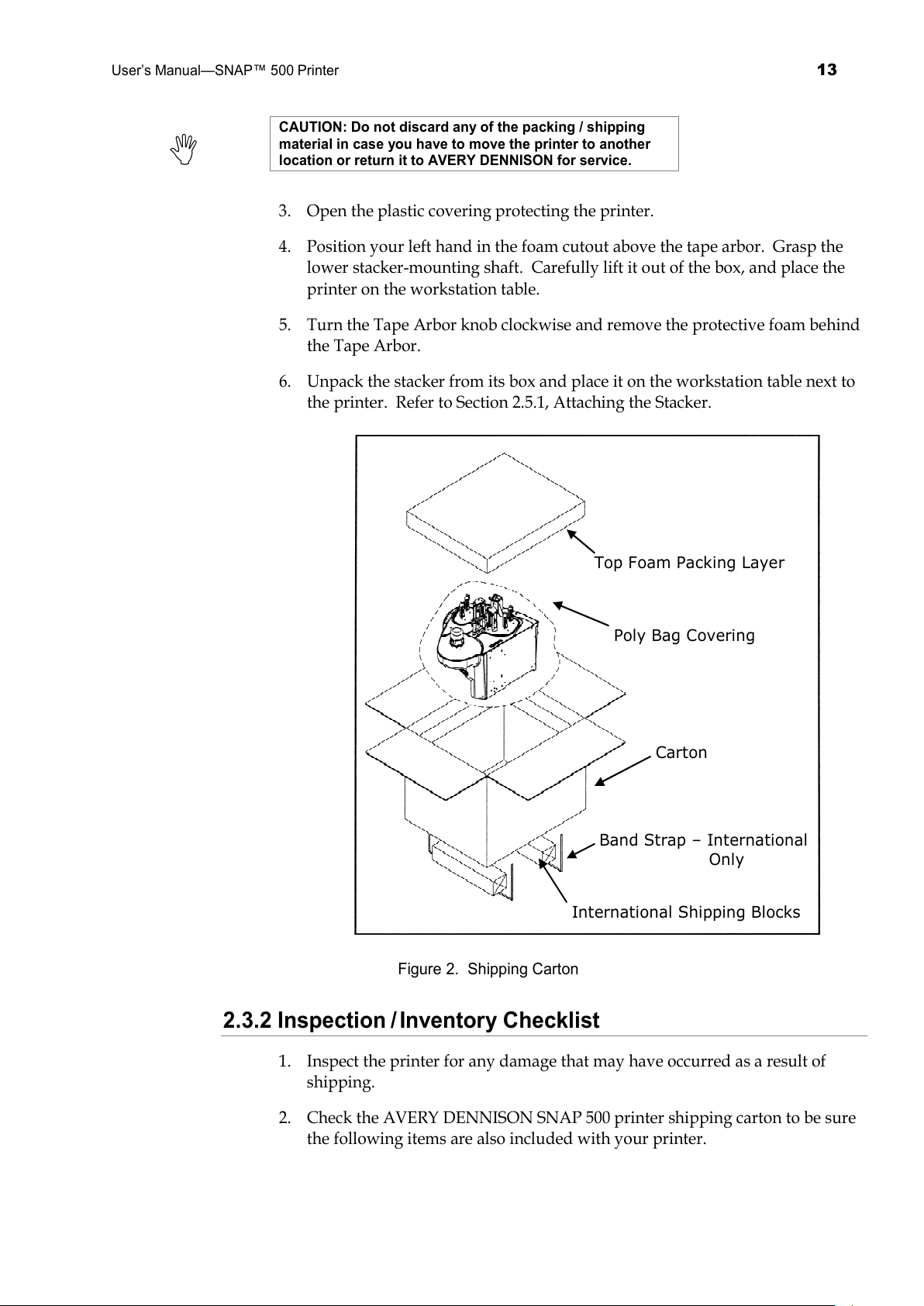
2. Remove the foam-packing layer (see Figure 2).
All manuals and user guides at all-guides.com
Page 13
User’s Manual—SNAP™ 500 Printer
13
CAUTION: Do not discard any of the packing / shipping
material in case you have to move the printer to another
location or return it to AVERY DENNISON for service.
3. Open the plastic covering protecting the printer.
4. Position your left hand in the foam cutout above the tape arbor. Grasp the
lower stacker-mounting shaft. Carefully lift it out of the box, and place the
printer on the workstation table.
5. Turn the Tape Arbor knob clockwise and remove the protective foam behind
the Tape Arbor.
6. Unpack the stacker from its box and place it on the workstation table next to
the printer. Refer to Section 2.5.1, Attaching the Stacker.
Top Foam Packing Layer
Poly Bag Covering
Carton
Band Strap – International
Only
International Shipping Blocks
Figure 2. Shipping Carton
2.3.2 Inspection / Inventory Checklist
1. Inspect the printer for any damage that may have occurred as a result of
shipping.
2. Check the AVERY DENNISON SNAP 500 printer shipping carton to be sure
the following items are also included with your printer.
All manuals and user guides at all-guides.com
Page 14
14
User’s Manual—SNAP™ 500 Printer
AVERY DENNISON SNAP 500 printer User's Manual
Serial Cable
A quick-disconnect power cord for 115-Volt printer)
PCMate Platinum software (CD)
Instructional Video (CD)
3. If you see obvious damage to the printer, or if any items listed above are
missing, contact AVERY DENNISON for further instructions.
• In the U.S.A., call (570) 888-6641, select option for Customer Service.
• In all other countries, please contact your local AVERY DENNISON supplier.
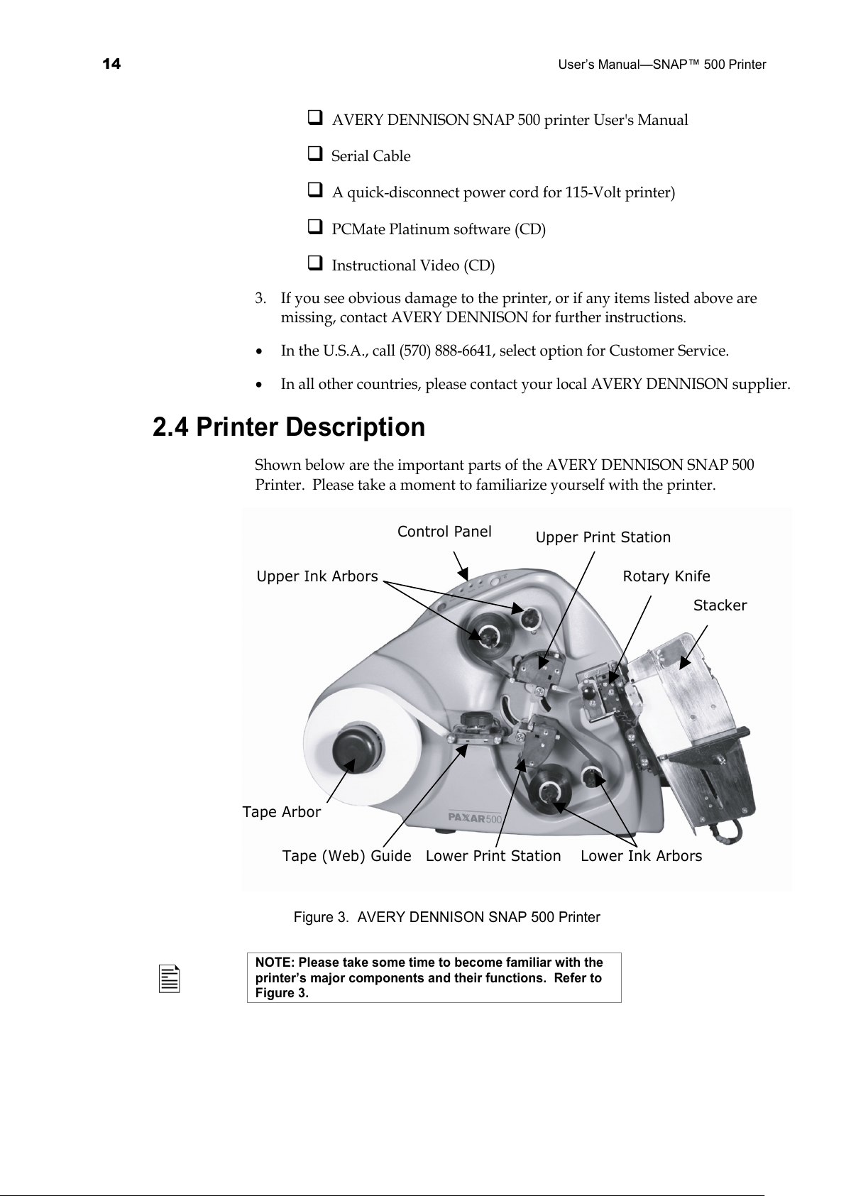
2.4 Printer Description
Shown below are the important parts of the AVERY DENNISON SNAP 500
Printer. Please take a moment to familiarize yourself with the printer.
Upper Ink Arbors
Control Panel
Tape Arbor
Lower Print Station
Tape (Web) Guide
Upper Print Station
Rotary Knife
Stacker
Lower Ink Arbors
Figure 3. AVERY DENNISON SNAP 500 Printer
NOTE: Please take some time to become familiar with the
printer’s major components and their functions. Refer to
Figure 3.
All manuals and user guides at all-guides.com
Page 15
User’s Manual—SNAP™ 500 Printer
15
• The Tape Arbor holds the tape supply roll. By rotating the outer knob
clockwise or counterclockwise, you can adjust the Tape Arbor to
accommodate tapes ranging from ½ inch - 2 ¼ inches (12.7 mm - 57.2 mm)
wide.
• The Tape or Web Guide is adjusted by rotating the black knob.
• The Upper and Lower Print Stations are equipped with knobs for adjusting
print head pressure and print density to control the print quality.
• The Upper and Lower Ink Arbors are spring loaded, allowing them to open
up and self center the ink cores to each other. They accommodate ink rolls
ranging from 1 inch - 2 ½ inches with Inch Adapter or from 25 mm – 60 mm
with the Metric Adapter.
• A Rotary Knife Assembly is supplied with the printer. For applications
utilizing woven tapes, a Sonic Knife accessory option providing ultrasonic
cutting and sealing is available.
• The Stacker collects the finished, printed labels. You can adjust it to
accommodate a variety of label tapes and short or long labels. Once the
stacker reaches the bottom, the printer will stop, indicate the stacker is full,
and allow you to remove the labels.
• The Control Panel with buttons and LED’s indicate printer status and
information about specific jobs.
WARNING: This is a class A product. In a domestic
environment this product may cause radio interference in
which case the user may be required to take adequate
measures.
All manuals and user guides at all-guides.com
Page 16
16
User’s Manual—SNAP™ 500 Printer
2.5 Setting Up the Printer
2.5.1 Attaching the Stacker
Platform
Label Stop
Rotary Knife
Shafts
Stacker Sensor
Switch
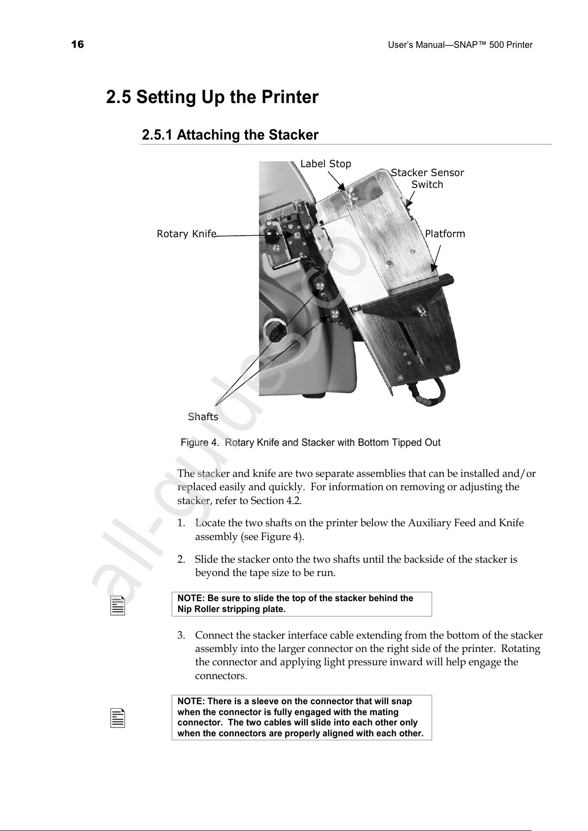
Figure 4. Rotary Knife and Stacker with Bottom Tipped Out
The stacker and knife are two separate assemblies that can be installed and/or
replaced easily and quickly. For information on removing or adjusting the
stacker, refer to Section 4.2.
1. Locate the two shafts on the printer below the Auxiliary Feed and Knife
assembly (see Figure 4).
2. Slide the stacker onto the two shafts until the backside of the stacker is
beyond the tape size to be run.
NOTE: Be sure to slide the top of the stacker behind the
Nip Roller stripping plate.
3. Connect the stacker interface cable extending from the bottom of the stacker
assembly into the larger connector on the right side of the printer. Rotating
the connector and applying light pressure inward will help engage the
connectors.
NOTE: There is a sleeve on the connector that will snap
when the connector is fully engaged with the mating
connector. The two cables will slide into each other only
when the connectors are properly aligned with each other.
All manuals and user guides at all-guides.com
all-guides.com
Page 17
User’s Manual—SNAP™ 500 Printer
17
2.5.2 Checking the Main Fuse Configuration
WARNING: Before powering on the printer, you must
check to be sure the main fuses on the AC power
receptacle are set for the appropriate voltage for your
location (Line voltage of 90-132VAC @ 50-60Hz, single
phase or 180-265VAC @ 50-60Hz, single phase).
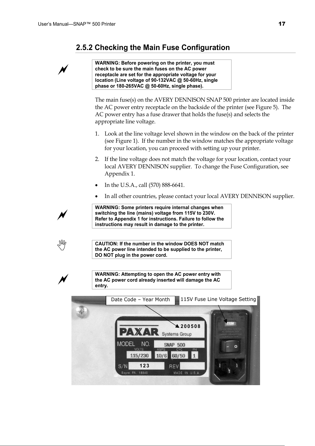
The main fuse(s) on the AVERY DENNISON SNAP 500 printer are located inside
the AC power entry receptacle on the backside of the printer (see Figure 5). The
AC power entry has a fuse drawer that holds the fuse(s) and selects the
appropriate line voltage.
1. Look at the line voltage level shown in the window on the back of the printer
(see Figure 1). If the number in the window matches the appropriate voltage
for your location, you can proceed with setting up your printer.
2. If the line voltage does not match the voltage for your location, contact your
local AVERY DENNISON supplier. To change the Fuse Configuration, see
Appendix 1.
• In the U.S.A., call (570) 888-6641.
• In all other countries, please contact your local AVERY DENNISON supplier.
WARNING: Some printers require internal changes when
switching the line (mains) voltage from 115V to 230V.
Refer to Appendix 1 for instructions. Failure to follow the
instructions may result in damage to the printer.
CAUTION: If the number in the window DOES NOT match
the AC power line intended to be supplied to the printer,
DO NOT plug in the power cord.
WARNING: Attempting to open the AC power entry with
the AC power cord already inserted will damage the AC
entry.
115V Fuse Line Voltage Setting
2 0 0 5 0 8
1 2 3
Date Code
–
Year Month
All manuals and user guides at all-guides.com
Page 18
18
User’s Manual—SNAP™ 500 Printer
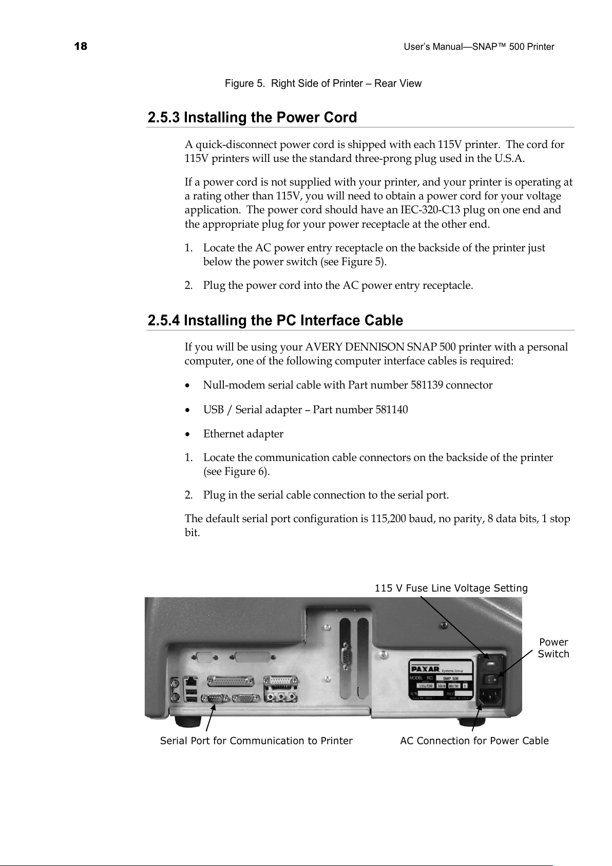
Figure 5. Right Side of Printer – Rear View
2.5.3 Installing the Power Cord
A quick-disconnect power cord is shipped with each 115V printer. The cord for
115V printers will use the standard three-prong plug used in the U.S.A.
If a power cord is not supplied with your printer, and your printer is operating at
a rating other than 115V, you will need to obtain a power cord for your voltage
application. The power cord should have an IEC-320-C13 plug on one end and
the appropriate plug for your power receptacle at the other end.
1. Locate the AC power entry receptacle on the backside of the printer just
below the power switch (see Figure 5).
2. Plug the power cord into the AC power entry receptacle.
2.5.4 Installing the PC Interface Cable
If you will be using your AVERY DENNISON SNAP 500 printer with a personal
computer, one of the following computer interface cables is required:
• Null-modem serial cable with Part number 581139 connector
• USB / Serial adapter – Part number 581140
• Ethernet adapter
1. Locate the communication cable connectors on the backside of the printer
(see Figure 6).
2. Plug in the serial cable connection to the serial port.
The default serial port configuration is 115,200 baud, no parity, 8 data bits, 1 stop
bit.
115 V Fuse Line Voltage Setting
Serial Port for Communication to Printer AC Connection for Power Cable
Power
Switch
All manuals and user guides at all-guides.com
Page 19

User’s Manual—SNAP™ 500 Printer
19
Figure 6. Rear View of the Printer
All manuals and user guides at all-guides.com
Page 20
20
User’s Manual—SNAP™ 500 Printer
2.5.5 Installing PCMate Platinum Software
The software used to drive the AVERY DENNISON family of printers is covered
in a separate manual. The PCMate Platinum software is a Windows® application
used to create formats for the AVERY DENNISON SNAP 500 printer as well as
all other AVERY DENNISON control printers.
The printer is also capable of operating directly from a mainframe when using
the RS232 interface and AVERY DENNISON's command language (PCL).
NOTE: When using PCMate Platinum with virtual control /
display interface, the remote control / display module will
function. However, it is only needed when the printer is
driven by a mainframe computer or other software
interface packages.
2.6 Printing a Test Label
2.6.1 Loading Supplies
Before you can print a test label, the printer must be loaded with tape and ink.
Refer to section 3.1 for instructions on loading the tape and ink.
2.6.2 Turning the Printer on
Turn the power switch on. The power switch is located on the back of the
printer, just above the power cord.
The four lights on the Printer Control Panel will come on for a few seconds, and
then all four lights will start to flash. This indicates that the printer is performing
its internal diagnostic tests. After several seconds, the lights will stop flashing
and the Ready light will come on. This indicates that the printer is ready.
If any problems occur, see sections 9 and 10, Troubleshooting.
2.6.2 Selecting the Test Format
There are two test formats built into the printer. These are selected using the
Option Menu System. The steps below describe how to select one of the test
formats. For more information on the Option Menu System, see section 3.4.
When the instructions say to press a button, press the
button for a short time and release it. When the
instructions say to press and hold a button, press the
button and hold it down until the printer responds.
When you are in the Option Menu System, you can get out
by pressing and holding the Voice button until the printer
says “Returning to print mode.”
All manuals and user guides at all-guides.com
Page 21
User’s Manual—SNAP™ 500 Printer
21
1. Press and hold the Voice button until the printer says “Press Start for Test
Patterns.”
2. Press the Start button. The printer will say “Press Start for Test Pattern 1.” If
you want to print test pattern 1, press the Start Button, then go to step 3. If you
want to print test pattern 2, press the Voice button. The printer will say “Press
Start for Test Pattern 2.” Press the Start button.
3. The printer will say “Ready to print test pattern 1 (or 2), Returning to print
mode.” At this time the Data light will come on. The printer is now ready to
print the test labels.
2.6.3 Printing the Test Labels
Press the Start button. The stacker (if installed) will move the platform to its start
position and the printer will begin printing the test labels.
If any problems occur, either the Supply or Error light will come on. If this
happens, press the Voice button and the printer will say a message telling what
the problem is. Correct the problem and press the Start button again. Repeat
this until the printer runs continuously.
If you can’t get the printer to run, refer to sections 9 and 10 Troubleshooting.
All manuals and user guides at all-guides.com
all-guides.com
Page 22
22
User’s Manual—SNAP™ 500 Printer
3.0 Operation
3.1 Loading Supplies
Your AVERY DENNISON SNAP 500 printer is designed with both upper and
lower ink supply stations.
The ink arbors have a spring-loaded latch, which self-centers the roll of ink to
ensure smooth tracking through the machine. If you are using supplies based on
the metric system, ensure that the latch on the arbor is gray. If you are using
supplies based on the inch, ensure that the latch on the arbors is black.
The ink cores have splines on their inside surfaces. These splines align with the
grooves in the ink arbors. When installing the ink roll, the splines must align
with the grooves.
3.1.1 Installing Ink to the Top Ink Supply Station
1. Install an empty ink core on the upper ink rewind arbor. It is important that
the core be the same width as the core of the ink being used.
NOTE: The empty ink core should be the same width as
the ink supply roll.
a. Press the latch, rotate the core slightly to align the splines and
grooves, and slide it gently onto the arbor. Release the latch as soon
as the core starts to slide on the arbor.
b. As you slide the core onto the arbor, you will hear a clicking noise as
the latch ratchets onto the core. When the core is centered on the
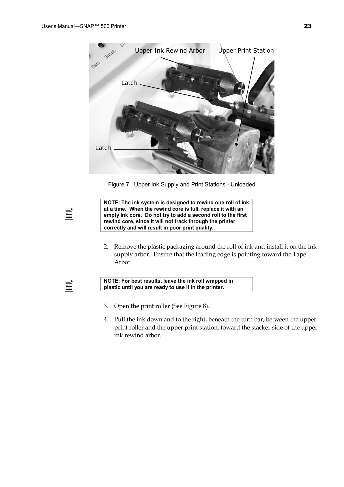
arbor, it will stop. See Figure 7.
CAUTION: To avoid damaging the print head, the ink
supply roll should be ¼ inch (6 mm) wider than the tape.
All manuals and user guides at all-guides.com
Page 23
User’s Manual—SNAP™ 500 Printer
23
Upper Ink Rewind Arbor
Upper Print Station
Latch
Latch
Figure 7. Upper Ink Supply and Print Stations - Unloaded
NOTE: The ink system is designed to rewind one roll of ink
at a time. When the rewind core is full, replace it with an
empty ink core. Do not try to add a second roll to the first
rewind core, since it will not track through the printer
correctly and will result in poor print quality.
2. Remove the plastic packaging around the roll of ink and install it on the ink
supply arbor. Ensure that the leading edge is pointing toward the Tape
Arbor.
NOTE: For best results, leave the ink roll wrapped in
plastic until you are ready to use it in the printer.
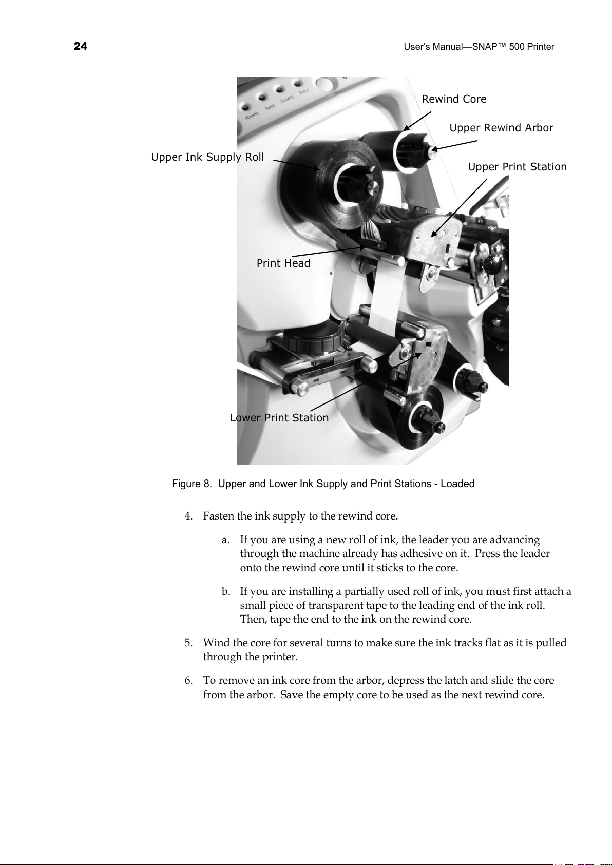
3. Open the print roller (See Figure 8).
4. Pull the ink down and to the right, beneath the turn bar, between the upper
print roller and the upper print station, toward the stacker side of the upper
ink rewind arbor.
All manuals and user guides at all-guides.com
Page 24
24
User’s Manual—SNAP™ 500 Printer
Rewind Core
Upper Print Station
Upper Rewind Arbor
Upper Ink Supply Roll
Print Head
Lower Print Station
Figure 8. Upper and Lower Ink Supply and Print Stations - Loaded
4. Fasten the ink supply to the rewind core.
a. If you are using a new roll of ink, the leader you are advancing
through the machine already has adhesive on it. Press the leader
onto the rewind core until it sticks to the core.
b. If you are installing a partially used roll of ink, you must first attach a
small piece of transparent tape to the leading end of the ink roll.
Then, tape the end to the ink on the rewind core.
5. Wind the core for several turns to make sure the ink tracks flat as it is pulled
through the printer.
6. To remove an ink core from the arbor, depress the latch and slide the core
from the arbor. Save the empty core to be used as the next rewind core.
All manuals and user guides at all-guides.com
Page 25
User’s Manual—SNAP™ 500 Printer
25
3.1.2 Installing Ink to the Bottom Ink Supply Station
Installing Ink on the Bottom Print Station is done in the same way as the Top
Print Station, except that the ink runs up over the Turnbar, across the printhead
to the rewind arbor.
3.1.3 Loading the Tape
Before loading a roll of tape, you will need to be familiar with the following parts
of the AVERY DENNISON SNAP 500 printer (Refer to Figures 9 and 10).
The Tape Arbor is designed to clamp the core of the tape supply rolls to hold
them in place during printing operations. By rotating the outer knob on the tape
arbor, you can adjust for roll widths ranging in size from ½ inch - 2 ¼ inches
(12.7 mm – 57.2 mm). This helps keep the tape straight while it moves to the
center of the print head. To function properly, the tape roll must be wound
firmly and centered on the core with no telescoping of the roll. You do not need
to make any other adjustments.
The Tape or Web Guide is located between the Tape Arbor and Lower Print
Station and guides the tape through the machine toward the print head. The
black knob located above the web guide controls the width of the guides.
Turning the knob clockwise will widen the web guides, while counterclockwise
turns will narrow the web guides.
The Upper and Lower Print Stations on the AVERY DENNISON SNAP 500
printer are stationary. The main feed is the print roller located in the upper print
station. (See Figure 10). The rollers swing open and closed for threading and
printing. These rollers are held in position for printing with latches on both the
inside and outside end of the rollers. This roller must be closed in order for the
tape to feed through the printer.
NOTE: The upper print roller must be closed in order for
the printer to operate. If you are printing two-sided labels,
both print rollers must be closed in order for the printer to
operate. If a two-sided label design is sent to the printer
and the lower print roller is open, the Error LED will light
up and the printer will stop. If you are printing single-
sided labels, the lower print roller should remain open so
the ink rolls will not rotate.
The Auxiliary Feed is the assembly located in front of the knife. It works with
the main feed or the upper print roller to maintain proper tension of the tape as it
moves through the printer from the top print station into the Knife and Nip
rollers. The Auxiliary Feed has a knob, which is used to manually advance the
material through the knife, the nip roller, and into the stacker.
New rolls of Supply Tape are sealed and packaged individually. When you are
ready to load the tape, remove the packaging and follow the steps below.
All manuals and user guides at all-guides.com
Page 26

26
User’s Manual—SNAP™ 500 Printer
1. Remove the transparent tape holding the end of the supply tape to the outer
part of the roll. To avoid damaging the rollers or print heads, use scissors to
cut off any portion of the supply tape that has adhesive on it.
2. Rotate the knob counterclockwise to retract the ”fingers.”
3. To install the tape supply roll, begin with the leading end at the top of the
roll.
4. Slide the tape supply roll onto the Tape Arbor (see Figure 9).
5. Rotate the knob clockwise quickly to extend the retraction fingers that hold
the supply roll in place.
6. With both print rollers in the open position, pull the tape from the top of the
supply roll.
Upper Print Station
Retraction Fingers
Tape Arbor
Tape (Web) Guide
Lower Print Station
Figure 9. Tape Supply Through Print Stations
7. Pull the roll of tape under the tape (web) guides.
8. Continue threading the tape between the print rollers, through the feed roller
and up to the auxiliary feed.
9. Rotate the black knob on the auxiliary feed counterclockwise and advance
the tape through the knife and nip rollers and into the stacker (until it
extends about ½ inch or 10 mm - 15 mm from the rollers).
10. If the tape will not advance through the knife, refer to Section 5.4.2, Knife
Home Position Adjustment.
11. Close the upper and lower print rollers.
All manuals and user guides at all-guides.com
all-guides.com
Page 27
User’s Manual—SNAP™ 500 Printer
27
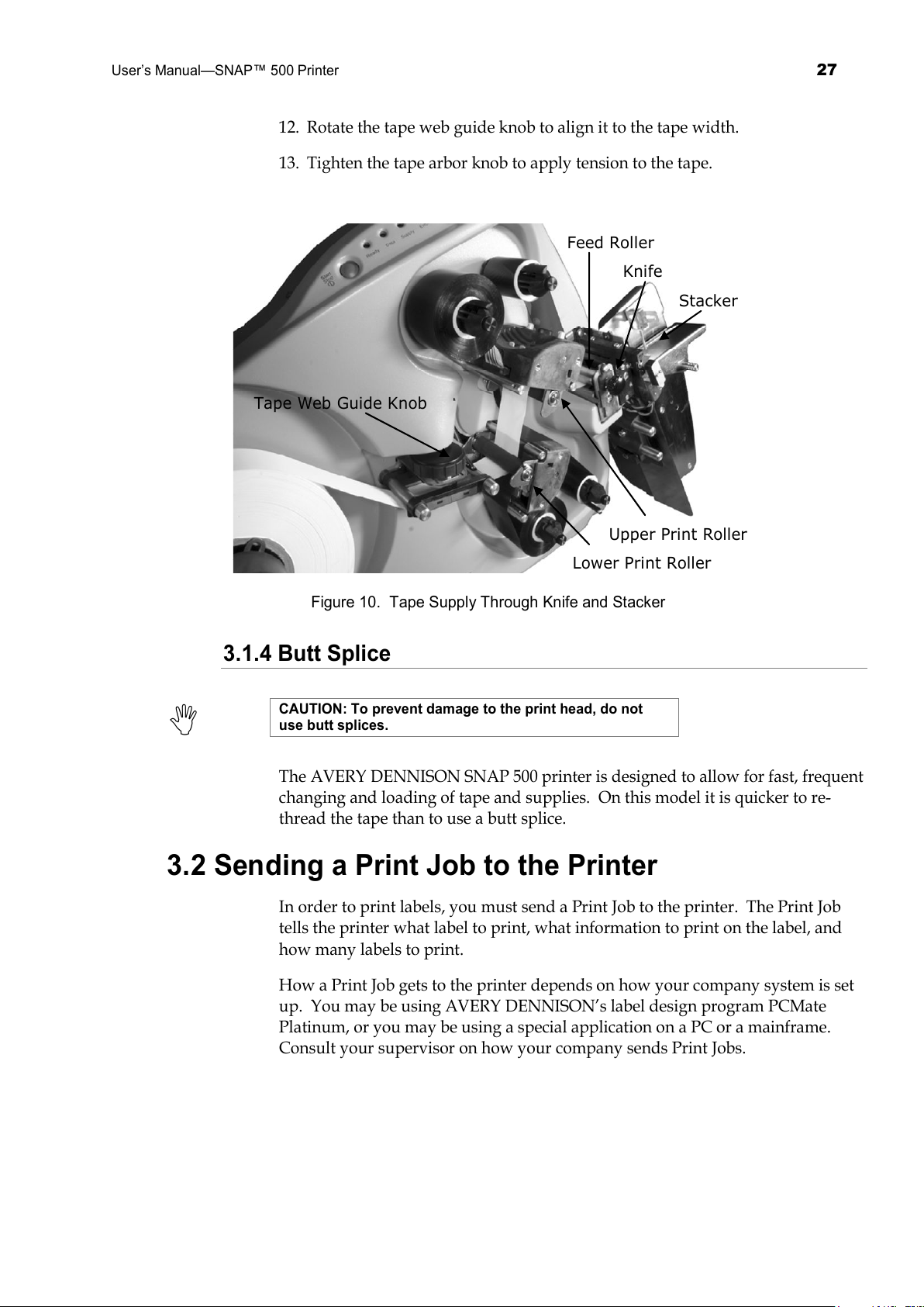
12. Rotate the tape web guide knob to align it to the tape width.
13. Tighten the tape arbor knob to apply tension to the tape.
Feed Roller
Knife
Stacker
Upper Print Roller
Lower Print Roller
Tape Web Guide Knob
Figure 10. Tape Supply Through Knife and Stacker
3.1.4 Butt Splice
CAUTION: To prevent damage to the print head, do not
use butt splices.
The AVERY DENNISON SNAP 500 printer is designed to allow for fast, frequent
changing and loading of tape and supplies. On this model it is quicker to re-
thread the tape than to use a butt splice.
3.2 Sending a Print Job to the Printer
In order to print labels, you must send a Print Job to the printer. The Print Job
tells the printer what label to print, what information to print on the label, and
how many labels to print.
How a Print Job gets to the printer depends on how your company system is set
up. You may be using AVERY DENNISON’s label design program PCMate
Platinum, or you may be using a special application on a PC or a mainframe.
Consult your supervisor on how your company sends Print Jobs.
All manuals and user guides at all-guides.com
Page 28
28
User’s Manual—SNAP™ 500 Printer
3.3 Printing Labels
3.3.1 The Control Panel
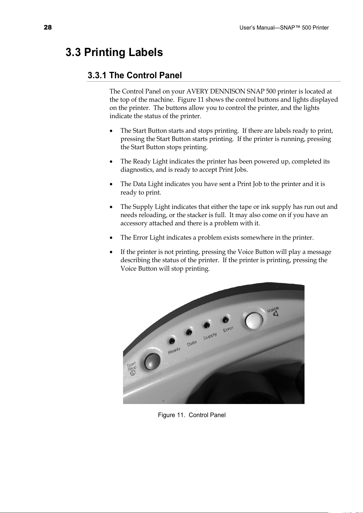
The Control Panel on your AVERY DENNISON SNAP 500 printer is located at
the top of the machine. Figure 11 shows the control buttons and lights displayed
on the printer. The buttons allow you to control the printer, and the lights
indicate the status of the printer.
• The Start Button starts and stops printing. If there are labels ready to print,
pressing the Start Button starts printing. If the printer is running, pressing
the Start Button stops printing.
• The Ready Light indicates the printer has been powered up, completed its
diagnostics, and is ready to accept Print Jobs.
• The Data Light indicates you have sent a Print Job to the printer and it is
ready to print.
• The Supply Light indicates that either the tape or ink supply has run out and
needs reloading, or the stacker is full. It may also come on if you have an
accessory attached and there is a problem with it.
• The Error Light indicates a problem exists somewhere in the printer.
• If the printer is not printing, pressing the Voice Button will play a message
describing the status of the printer. If the printer is printing, pressing the
Voice Button will stop printing.
Figure 11. Control Panel
All manuals and user guides at all-guides.com
Page 29
User’s Manual—SNAP™ 500 Printer
29
3.3.2 Printing
Once a print job has been sent to the printer, the Data light will come on. You
can then press the Start Button to start printing.
When printing starts, the stacker will move the platform up and down to
position it in the correct position. Then the printer will start printing labels.
As the printer prints, the cut labels will drop onto the top of the stack. As the
stack grows, the stacker platform moves down so that the top of the stack stays
in the same position.
3.3.2.1 Handling the Leader
When you start printing for the first time, or after some errors, the printer will
create a leader. The leader is a longer piece of material that may be blank or may
have some partially printed labels. These labels are not usable and are not part
of the print job.
When the printer creates a leader, grab it as it comes out of the nip rollers and
pull it out of the stacker when the printer does the first cut. (If you are not using
the stacker, or you are using some other accessory such as a Rewinder or Looper,
you may need to handle the leader differently.)
3.3.3 Errors
If the printer encounters a problem during printing, it will stop printing and
either the Supply or Error light will come on. The Supply light means that there
is a problem with either the ink or the tape, or the stacker is full. The error light
means that there is some other problem with the printer.
There are three ways to determine what the problem is:
1. Press the Voice button. A message will play that describes the problem.
2. The problem will be displayed in the Printer Status box on the Virtual
Control Panel in PCMate Platinum. See section 8.0 for a description of the
Virtual Control Panel.
3. The problem will be displayed on the Remote Front Panel option, if it is
installed. See section 7.0 for a description of the Remote Front Panel.
Correct the problem and press the Start Button to start printing again.
NOTE: If the error condition no longer exists, the printer
will start. It is not necessary to press the Start button
twice as is required with previous AVERY DENNISON
printer models. If the error continues to recur, contact
your local AVERY DENNISON representative.
All manuals and user guides at all-guides.com
Page 30
30
User’s Manual—SNAP™ 500 Printer
3.3.4 End of Day
When the printer finishes printing all the print jobs that have been sent, it will
stop with a few labels left to print. This allows you to send another next print job
and print it without wasting tape and ink. The Data light will flash to indicate
this condition.
When this occurs, you may send another print job. The printer will start up
automatically.
If you are finished for the day or you need to change tape or ink for the next
print job, press the Start Button. The printer will print the last few labels of the
last print job. You can then turn off the printer or change the tape and ink for the
next print job.
3.3.5 Clearing Print Jobs
If you have sent print jobs to the printer and do not want to print the labels, press
and hold both the Start/Stop and Voice buttons simultaneously. After about 2
seconds, the printer will say “Clearing Current Batch.” If there is only one print
job, the Data light will go out.
If there are more than one print job and you only want to clear the current one,
release the buttons.
If there are more than one print job and you want to clear them all, continue to
hold the buttons until the printer says, “Clearing All Batches.”
3.3.6 Using Pre-Printed Tape
When using pre-printed tape, the printer must detect a sense mark on the tape in
order to print in the proper place. There a three options for detecting the sense
mark:
• A top reflective sensor is standard on all AVERY DENNISON SNAP 500
printers. This sensor will detect a black sense mark on the top surface of
a white tape, and is mounted in the top right-hand post that holds the
web guide. It is fixed in the center of the tape and cannot be moved.
• A bottom reflective sensor is an option. It is the same as the top reflective
sensor, except it will detect a black sense mark printed on the bottom of
the tape. When installed, it is mounted in a post beneath the right-hand
post that holds the web guide. It is also fixed in the center of the tape
and cannot be moved.
• A contrast sensor is also an option. This sensor will detect a colored
sense mark on the top surface of a colored tape. When installed, it is
mounted on the top left-hand post that holds the web guide. It is
movable across the web, so that the sense mark does not have to be
All manuals and user guides at all-guides.com
Page 31
User’s Manual—SNAP™ 500 Printer
31
centered on the tape. Refer to Appendix 7 for instructions on teaching
the sensor.
3.3.6.1 Selecting the Sensor
The top and bottom reflective sensors can be selected in one of two ways. First,
the sensor type can be selected as part of the format (see the PCMate Platinum
manual or the PCL manual for details).
The sensor type that is selected in the format can be overridden using the Virtual
Control Panel (see section 8.0) or the Remote Front Panel (see section 7.0).
The printer does not know if the optional bottom reflective
or contrast sensors are installed. If one of these sensors
is selected but not installed, the printer will not operate
properly.
3.3.6.2 Aligning the Tape to the Sensor
In order to work properly, the tape must be aligned to the sensor before starting
to print. To do this, close one or both print-head rollers (depending on whether
the label is single- or double-sided) and use the Auxiliary Feed knob until the
sense mark is just to the left of the sensor. Then rotate the rewind ink arbors to
take up any slack and press the Start Button.
This alignment must be done anytime the printer would
normally create a leader. This will happen after most
errors. Do not align the tape after a normal stop or a
stacker full.
3.3.7 Feeding the tape
To feed the tape, press and hold the Start button. After a short delay, the printer
will feed tape though the printer. To stop the feed, release the Start button.
If you are in the middle of printing a batch, feeding the
tape will cause the printed labels between the printhead
and the knife to feed through without cutting. These labels
will be re-printed the next time you start printing. The
batch quantity will be correct.
3.4 Option Menu System
The Option Menu System allows you to
• Print test labels
• Play demos
All manuals and user guides at all-guides.com
all-guides.com
Page 32
32
User’s Manual—SNAP™ 500 Printer
• Set the voice volume.
When the instructions say to press a button, press the
button for a short time and release it. When the
instructions say to press and hold a button, press the
button and hold it down until the printer responds.
When you are in the Option Menu System, you can get out
by pressing and holding the Voice button until the printer
says “Returning to print mode.”
You will use the Start / Stop and Voice buttons to move through the Option
Menu System. Each time you press a key, a voice message will follow, or the
machine will initiate or stop an action. Regardless of which of the three
functions you want to select in the Option Menu System, you select it the same
way:
1. Press and hold the Voice button for about two seconds.
2. The Voice message will say, “Press Start for Test Pattern.”
3. If you do not want to run a test pattern, press the Voice button.
4. The voice message will say, “Press Start for Demos.”
5. If you do not want to listen to the demos, press the Voice button.
6. The voice message will respond with, “Press Start to Set Volume.”
7. If you do not want to change the speaker volume, press the Voice button.
8. The printer will say “Returning to Print Mode.” At this time the Option
Menu System is complete and the printer is back to normal operation.
For more information on how to utilize each of the three possibilities in the
Option Menu System, refer to Sections 3.4.1, Running Test Labels; 3.4.2, Using
Voice Demos; and 3.4.3, Setting / Adjusting Voice Button Volume. Appendix 8
contains a flowchart of the Option Menu System.
3.4.1 Running Test Labels
Your AVERY DENNISON SNAP 500 printer offers you two Test Patterns to run
before you proceed to production.
Test Pattern 1, consisting of a solid line down the middle on the front and back
of the label and a solid line across the web that is exactly 1” from the cut. This
test pattern is helpful in adjusting your print position to compensate for
mechanical tolerances in the printer.
Test Pattern 2 more closely resembles an actual label and can be used to make
adjustments to the printhead pressure and contrast (see sections 4.1.1 and 4.1.2).
All manuals and user guides at all-guides.com
Page 33
User’s Manual—SNAP™ 500 Printer
33
When you have determined which Test Pattern you wish to operate, use the
appropriate procedure.
NOTE: The printer is set up to print the selected label test
format in a very large quantity. You must manually start
and stop the printing to make any necessary adjustments
and to end the test run.
Test Pattern 1
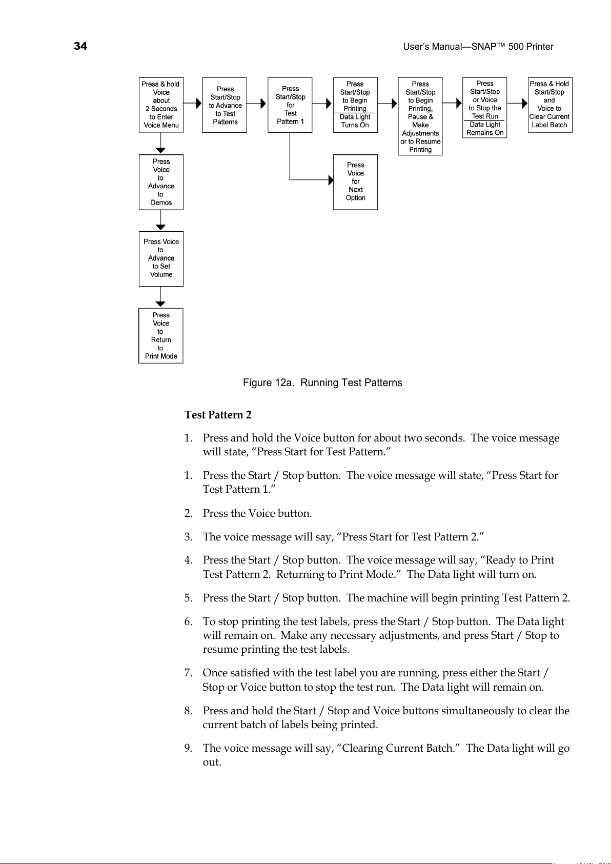
1. To run a test label, press and hold the Voice button about two seconds. The
voice message will say, “Press Start for Test Pattern.”
2. Press the Start / Stop Button. The voice message will say, “Press Start for
Test Pattern 1.”
3. Press the Start / Stop button. The voice message will respond with, “Ready
to Print Test Pattern 1. Returning to Print Mode.” The Data light will turn
on.
4. Press the Start / Stop button. The machine will begin printing Test Pattern 1.
5. To stop printing the test labels, press the Start / Stop button. The Data light
will remain on. Make any necessary adjustments, and press Start / Stop to
resume printing the test labels.
6. Once satisfied with the test label you are running, press either the Start /
Stop or Voice button to stop the test run. The Data light will remain on.
7. Press and hold the Start / Stop and Voice buttons simultaneously to clear the
current batch of labels being printed.
8. The voice message will say, “Clearing Current Batch.” The Data light will go
out.
If you want to run Test Pattern 2, you must first clear the batch, and begin with
Step 1 for Test Pattern 1.
All manuals and user guides at all-guides.com
Page 34
34
User’s Manual—SNAP™ 500 Printer
Figure 12a. Running Test Patterns
Test Pattern 2
1. Press and hold the Voice button for about two seconds. The voice message
will state, “Press Start for Test Pattern.”
1. Press the Start / Stop button. The voice message will state, “Press Start for
Test Pattern 1.”
2. Press the Voice button.
3. The voice message will say, “Press Start for Test Pattern 2.”
4. Press the Start / Stop button. The voice message will say, “Ready to Print
Test Pattern 2. Returning to Print Mode.” The Data light will turn on.
5. Press the Start / Stop button. The machine will begin printing Test Pattern 2.
6. To stop printing the test labels, press the Start / Stop button. The Data light
will remain on. Make any necessary adjustments, and press Start / Stop to
resume printing the test labels.
7. Once satisfied with the test label you are running, press either the Start /
Stop or Voice button to stop the test run. The Data light will remain on.
8. Press and hold the Start / Stop and Voice buttons simultaneously to clear the
current batch of labels being printed.
9. The voice message will say, “Clearing Current Batch.” The Data light will go
out.
All manuals and user guides at all-guides.com
Page 35
User’s Manual—SNAP™ 500 Printer
35
3.4.2 Using Voice Demos
To help you become more familiar with your AVERY DENNISON SNAP 500
printer, the machine is equipped with two voice demos. Demo 1 provides a basic
introduction to the printer. Demo 2, consisting of 21 separate voice messages,
reviews the basic features of the printer one-by-one.
NOTE: To exit the Voice menu, press and hold the Voice
button at the end of any voice prompt.
Demo 1
1. Press and hold the Voice button longer than two seconds to activate the
Option Menu System.
2. The voice message will say, “Press Start for Test Pattern.”
3. Press the Voice button.
4. The voice message will say, “Press Start for Demos.”
5. Press the Start button.
6. The voice message will say, “Press Start for Demo 1.”
7A. Press the Start button. The machine will play Demo 1 and exit.
Demo 2
If you want to select Demo 2, repeat steps 1-6 in the Demo 1 section above.
7B. Press the Voice button. The voice message will say, “Press Start for Demo
2.”
8. Press the Start button. This will activate the series of 21 voice messages. At
the end of each message, you can either press Voice to repeat the message, or
press Start to advance to the next message.
NOTE: When listening to Demo 2, press the Voice button
to repeat a message, and press the Start / Stop button to
advance to the next message.
9. After the last message plays, the machine states, “This concludes our demo.”
The machine exits by itself.
10. If you are at Step 7b above and you decide not to listen to Demo 2, press the
Voice button, which advances you to the Change Volume menu. The voice
message responds with, “Press Start to Set Volume.”
All manuals and user guides at all-guides.com
Page 36
36
User’s Manual—SNAP™ 500 Printer
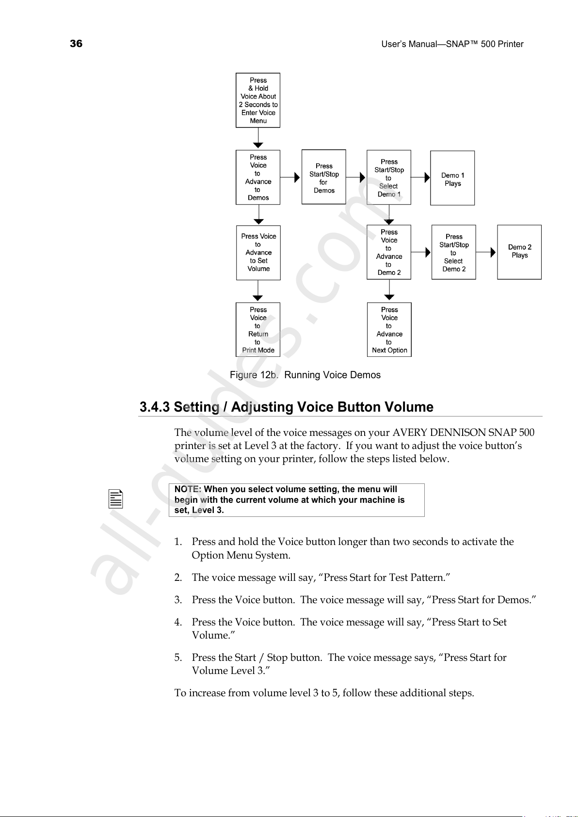
Figure 12b. Running Voice Demos
3.4.3 Setting / Adjusting Voice Button Volume
The volume level of the voice messages on your AVERY DENNISON SNAP 500
printer is set at Level 3 at the factory. If you want to adjust the voice button’s
volume setting on your printer, follow the steps listed below.
NOTE: When you select volume setting, the menu will
begin with the current volume at which your machine is
set, Level 3.
1. Press and hold the Voice button longer than two seconds to activate the
Option Menu System.
2. The voice message will say, “Press Start for Test Pattern.”
3. Press the Voice button. The voice message will say, “Press Start for Demos.”
4. Press the Voice button. The voice message will say, “Press Start to Set
Volume.”
5. Press the Start / Stop button. The voice message says, “Press Start for
Volume Level 3.”
To increase from volume level 3 to 5, follow these additional steps.
All manuals and user guides at all-guides.com
all-guides.com
Page 37
User’s Manual—SNAP™ 500 Printer
37
6. Press the Voice button. The voice message says, “Press Start for Volume
Level 4.”
7. Press the Voice button. The voice message says, “Press Start for Volume
Level 5.”
8. Press the Start button. The voice message says, “Volume Set to Level 5.
Returning to Print Mode.”
NOTE: Each time you press the Start button, the volume
level will increase by one increment until the maximum
level is reached.
If you want to decrease the voice volume to Level 1 or 2, follow Steps 1-7 above
and continue to press the Voice button until you reach the desired volume level.
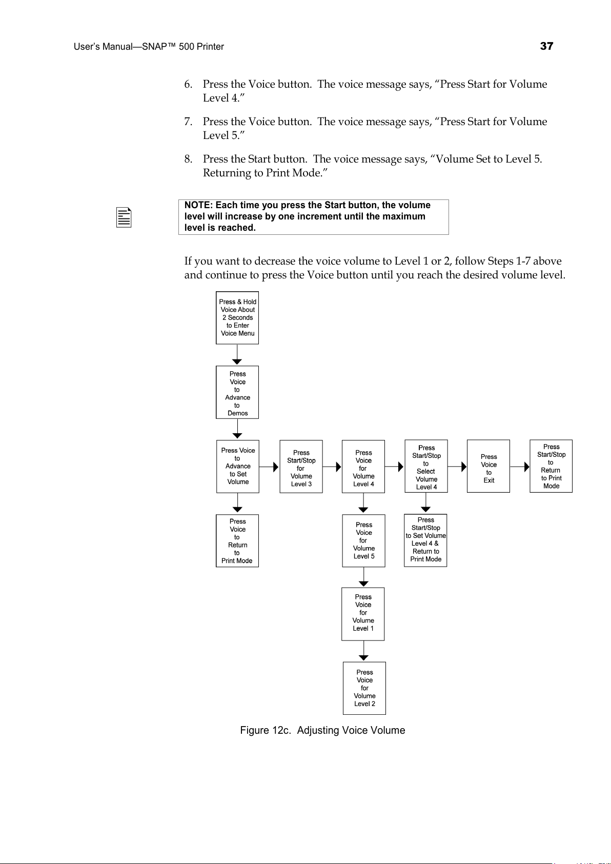
Figure 12c. Adjusting Voice Volume
All manuals and user guides at all-guides.com
Page 38

38
User’s Manual—SNAP™ 500 Printer
4.0 Making Adjustments
4.1 Print Head Adjustments
The two print stations on the AVERY DENNISON SNAP 500 printer are
stationary. The print rollers swing open for loading tape and ink and are closed
when the machine is printing. The rollers are held in the print position with a
latch on both the inside and outside end of the rollers.
When printing labels, there are two adjustments you may need to make to the
print stations: (1) adjust the print head pressure, and (2) adjust the contrast,
which controls print darkness (density).
4.1.1 Adjusting Print Head Pressure
Each print head has two print head pressure buttons, (see Figure 13).
To change the print head pressure settings, follow the steps listed below.
CAUTION: For extended print head life, use the lighter
print pressure setting whenever possible.
1. To decrease print head pressure, use a flat blade screwdriver, depress the
button and to turn both buttons ¼ turn (90 degrees) counterclockwise until
they are in the upper position.
2. To increase print head pressure, use the flat blade screwdriver, depress the
button and to turn each of the buttons clockwise until they are in the lower
position.
CAUTION: Ensure that both buttons on the print head are
in the same position.
The buttons will not rotate all the way around, only 90 degrees back and forth to
the desired setting.
All manuals and user guides at all-guides.com
Page 39
User’s Manual—SNAP™ 500 Printer
39
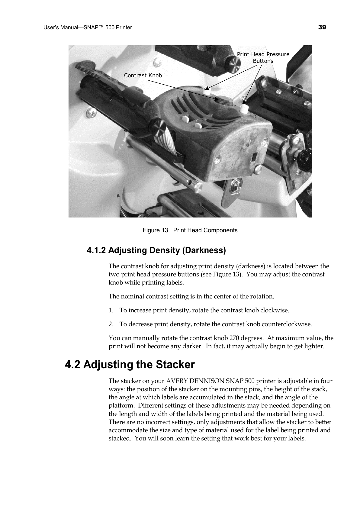
Contrast Knob
Print Head Pressure
Buttons
Figure 13. Print Head Components
4.1.2 Adjusting Density (Darkness)
The contrast knob for adjusting print density (darkness) is located between the
two print head pressure buttons (see Figure 13). You may adjust the contrast
knob while printing labels.
The nominal contrast setting is in the center of the rotation.
1. To increase print density, rotate the contrast knob clockwise.
2. To decrease print density, rotate the contrast knob counterclockwise.
You can manually rotate the contrast knob 270 degrees. At maximum value, the
print will not become any darker. In fact, it may actually begin to get lighter.
4.2 Adjusting the Stacker
The stacker on your AVERY DENNISON SNAP 500 printer is adjustable in four
ways: the position of the stacker on the mounting pins, the height of the stack,
the angle at which labels are accumulated in the stack, and the angle of the
platform. Different settings of these adjustments may be needed depending on
the length and width of the labels being printed and the material being used.
There are no incorrect settings, only adjustments that allow the stacker to better
accommodate the size and type of material used for the label being printed and
stacked. You will soon learn the setting that work best for your labels.
All manuals and user guides at all-guides.com
Page 40

40
User’s Manual—SNAP™ 500 Printer
4.2.1 Stacker Position
The stacker slides in and out on the mounting pins. This allows for proper
positioning of the stacker for the width of the label you are printing. The stacker
should be set so that the back wall of the stacker is just behind the back end of
the label where it comes out of the nip rollers.
The stacker mount bracket has a thumbscrew that locks the stacker in position
and also stiffens the mounting.
Adjusting the stacker angle (see section 4.2.3) will move the position of the back
wall. If you adjust the stacker angle, be sure to readjust the stacker position.
4.2.2 Toggle Switch
The stacker has two electronic sensors that set where the top of the stack is.
Depending on the size of the label to be collected on the stacker, use the toggle
switch to select from the two different electronic sensors (See Figure 5 and 11).
1. Determine the size of label to be printed.
a. For short feeds ranging from 1 - 2 inches (25 mm – 51 mm), use the
upper sensor.
b. For long feed and/or woven labels, use the lower sensor.
2. Depress the top portion of the toggle switch to use the upper sensor.
3. Depress the bottom portion of the toggle switch to use the lower sensor.
4.2.3 Stacker Angle
The angle of the stacker is adjustable, and can be tipped out a maximum of 20
degrees at the bottom from the vertical position shown in Figure 5. Since there is
no single stacker angle that is best for all label lengths and types of materials, you
can adjust the stacker angle to best accommodate each run.
1. When the feed is 2 inches (51 mm) or longer, or when using coated tapes, the
stacker works well with the bottom tipped out.
2. When using woven tapes, the stacker should be vertical or almost vertical.
All manuals and user guides at all-guides.com
Page 41
User’s Manual—SNAP™ 500 Printer
41
Label Stop
Stacker Sensor Switch
Shafts
Platform
Adjustment
Pin
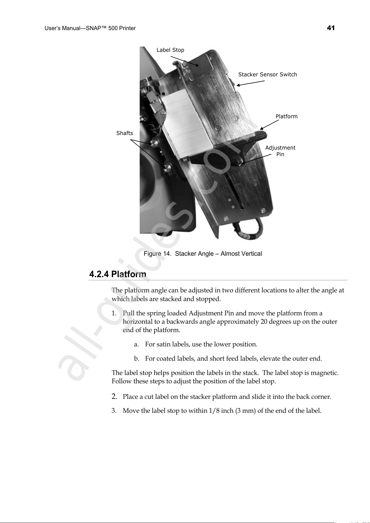
Figure 14. Stacker Angle – Almost Vertical
4.2.4 Platform
The platform angle can be adjusted in two different locations to alter the angle at
which labels are stacked and stopped.
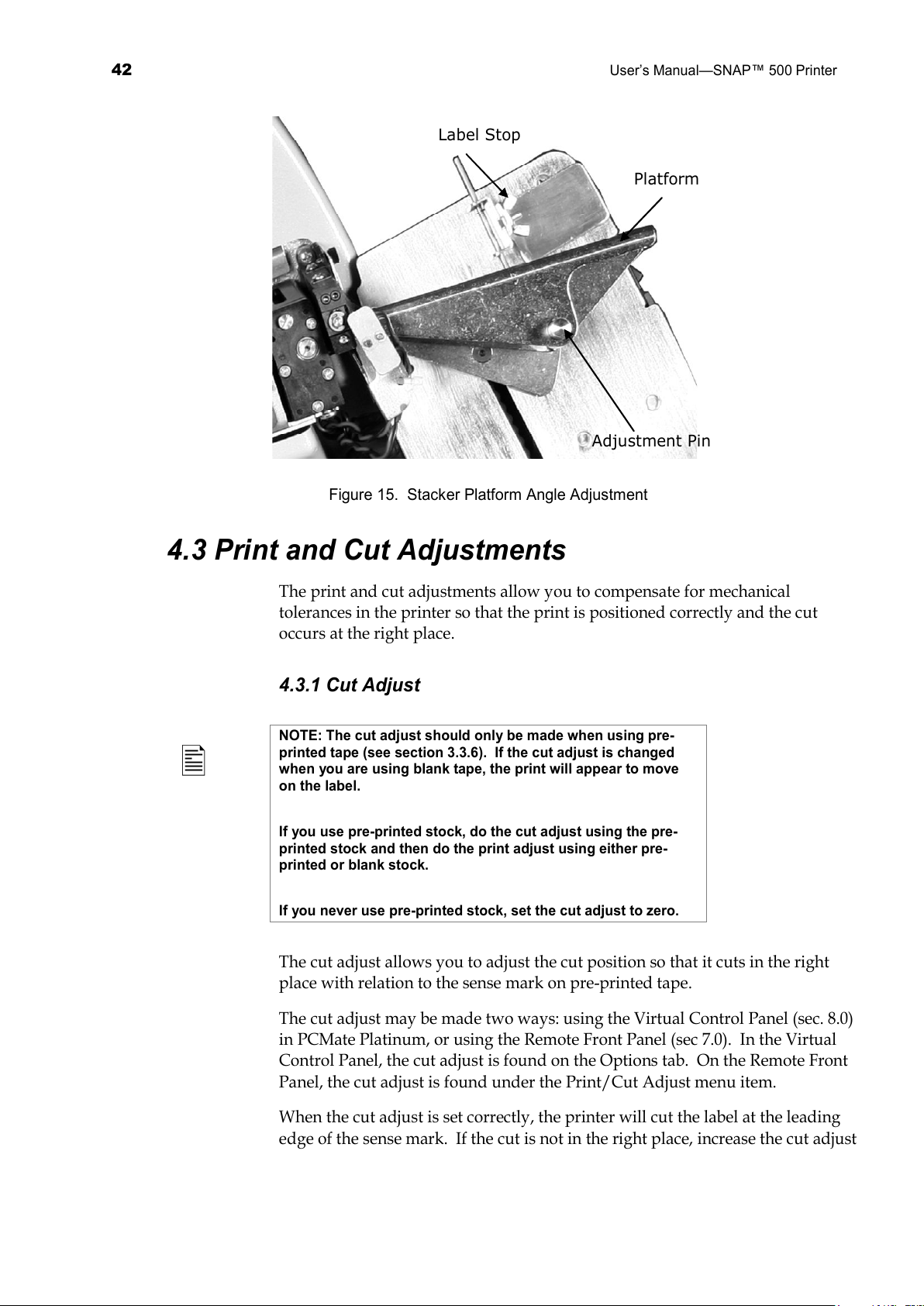
1. Pull the spring loaded Adjustment Pin and move the platform from a
horizontal to a backwards angle approximately 20 degrees up on the outer
end of the platform.
a. For satin labels, use the lower position.
b. For coated labels, and short feed labels, elevate the outer end.
The label stop helps position the labels in the stack. The label stop is magnetic.
Follow these steps to adjust the position of the label stop.
2. Place a cut label on the stacker platform and slide it into the back corner.
3. Move the label stop to within 1/8 inch (3 mm) of the end of the label.
All manuals and user guides at all-guides.com
all-guides.com
Page 42
42
User’s Manual—SNAP™ 500 Printer
Label Stop
Platform
Adjustment Pin
Figure 15. Stacker Platform Angle Adjustment
4.3 Print and Cut Adjustments
The print and cut adjustments allow you to compensate for mechanical
tolerances in the printer so that the print is positioned correctly and the cut
occurs at the right place.
4.3.1 Cut Adjust
NOTE: The cut adjust should only be made when using pre-
printed tape (see section 3.3.6). If the cut adjust is changed
when you are using blank tape, the print will appear to move
on the label.
If you use pre-printed stock, do the cut adjust using the pre-
printed stock and then do the print adjust using either pre-
printed or blank stock.
If you never use pre-printed stock, set the cut adjust to zero.
The cut adjust allows you to adjust the cut position so that it cuts in the right
place with relation to the sense mark on pre-printed tape.
The cut adjust may be made two ways: using the Virtual Control Panel (sec. 8.0)
in PCMate Platinum, or using the Remote Front Panel (sec 7.0). In the Virtual
Control Panel, the cut adjust is found on the Options tab. On the Remote Front
Panel, the cut adjust is found under the Print/Cut Adjust menu item.
When the cut adjust is set correctly, the printer will cut the label at the leading
edge of the sense mark. If the cut is not in the right place, increase the cut adjust
All manuals and user guides at all-guides.com
Page 43
User’s Manual—SNAP™ 500 Printer
43
value to move the cut to the right (looking at the printer) or decrease the value to
move the cut to the left. Each step is 0.003”/0.076mm.
4.3.2 Print Adjust
The print adjust allows you to move the print with relation to the cut. There are
two print adjusts, one for the top print station and one for the bottom print
station.
The print adjust may be made two ways: using the Virtual Control Panel (section
8.0) in PCMate Platinum, or using the Remote Front Panel (section 7.0). In the
Virtual Control Panel, the print adjust is found on the Options tab. On the
Remote Front Panel, the print adjust is found under the Print/Cut Adjust menu
item.
The best way to set the print adjust is to use Test Pattern 1 (see section 3.4.1). The
test pattern has a line printed across the tape that is 1” from the cut. Run a few
labels and measure the distance from the cut to the line. Then increase the print
adjust value to move the print to the right, or decrease the print adjust value to
move the print to the left. Each step is 0.003”/0/076mm. Repeat until the line is
in the correct place.
NOTE: It is common practice to use the print and cut adjusts
to “fine-tune” a format. If you do this, you will have to do it for
each format that you use. A better approach is to correct any
print position problems in the format, and to use the Sense To
Cut option to move the cut if necessary. Refer to the PCMate
Platinum manual for details.
4.4 Printer Features
The AVERY DENNISON SNAP 500 printer has many features that can be
controlled by the operator. Each of these features can be selected from either the
Virtual Control Panel (see section 8.0) or the Remote Control / Display Module
(see section 7.0). Unless otherwise noted, these features can be found in the
Options tab or the Virtual Control Panel or the Feature menu of the Remote
Front Panel. Refer to the sections on the Virtual Control Panel or the Remote
Front Panel for instruction on how to access these settings.
4.4.1 Selecting the Printer Language
The AVERY DENNISON SNAP 500 printer has the capability of presenting both
text and voice messages in multiple languages.
The printer is shipped with English as the only language.
Other languages must be installed separately. Contact your
local AVERY DENNISON Representative for information about
what languages are available and how to install another
language.
All manuals and user guides at all-guides.com
Page 44
44
User’s Manual—SNAP™ 500 Printer
In the Virtual Control panel, access the Options tab. To select the printer
language, click on the arrow in the Language box to drop down a list of available
languages. Click on the desired language. Then click on Apply or Close to
activate the selected language.
On the Remote Front Panel, select Feature Menu-Language. Use the Yes and No
keys to select the desired language, and then press the Enter key.
Selecting the printer language does not change the
PCMate Platinum language. See the PCMate Platinum
manual for information about changing languages.
4.4.2 Setting the Date and Time
The AVERY DENNISON SNAP 500 printer has a built-in clock and calendar.
You may change the date and time as follows:
In the Virtual Control Panel, access the Options Tab. The current printer date
and time is shown. You may change the values in the Date or Time box, or you
can simply click on the Sync to PC button to set the printer to the same date and
time as the PC. Click on Apply or Close to set the printer date and time.
In the Remote Front Panel, select Feature-Date or Feature-Time. Change the date
or time and press enter to set the new value.
4.4.3 Enabling or Disabling the Cutter
You may disable the cutter in order to use an accessory such as a Rewinder. If
the cutter is enabled, it will cut according to the Cut Count selected in the format.
If the cutter is disabled, it will not cut.
If you have an optional Sonic Knife installed, it will be also
be enabled or disabled using this command.
In the Virtual Control Panel, access the Options Tab. Click on the arrow in the
Cutter box. Select Enabled to run the cutter or Disabled to turn the cutter off.
In the Remote Front Panel, select Feature – Cutter. Use the Yes and No keys to
select Enabled or Disabled, then press the Enter key.
4.4.4 Selecting the Print Speed
The print speed is normally set in the format. You may override the format
setting and specify the speed you want the printer to run. This is useful if you
have formats that were designed for other AVERY DENNISON printers.
In the Virtual Control Panel, select the Options tab. Click on the arrow in the
Print Speed box to drop down a menu of print speed choices. Click on the
desired choice and click on Apply or Close to set the print speed.
All manuals and user guides at all-guides.com
Page 45
User’s Manual—SNAP™ 500 Printer
45
In the Remote Front Panel, select Feature-Print Speed. Use the Yes and No keys
to select the desired choice and press the Enter key.
The available choices are:
• Format – use the print speed specified in the format. If the print speed
does not exist in the AVERY DENNISON SNAP 500 printer, it will use
the closest print speed that is not greater. For example, if the format was
designed for a 676 printer and calls for 5 ips, the AVERY DENNISON
SNAP 500 printer will use 4.5 ips.
• Translate – uses the corresponding speed from the printer specified in the
format. For example, if the format was designed for a 676 printer and
called for 5 ips (the third speed in the printer’s speed list of 3,4, and 5
ips), the AVERY DENNISON SNAP 500 printer would use 6 ips, which is
the third speed in its speed list of 3, 4.5, 6, and 7 ips.
• 3, 4.5, 6 or 7 – selects the desired print speed.
4.4.5 Selecting the Flagging Mode
This selection allows you override the flagging mode specified in the format. It
is set in the same way as the Print Speed.
The available selections are:
• Format – uses the flagging mode specified in the format
• Side-step – This selection is for the High Volume Stacker, which is not
available for the AVERY DENNISON SNAP 500 printer. Do not select
this.
• Disabled – Disables flagging. No flagging will be done.
4.4.6 Selecting the Sense Mark Type
This selection allows you to override the sense mark type (none, top reflective or
bottom reflective) selected in the format. Its main purpose is to allow you to
activate the optional Contrast Sensor, since older formats or formats for other
AVERY DENNISON printers will not have the Contrast Sensor type.
This option is set in the same way as Print Speed.
The available selections are:
• Format – use the sense mark type specified in the format
• Top Reflective, Bottom Reflective, Contrast – selects the sensor type
• Disabled – ignores the sense mark. This is useful when designing a
format using blank tape to avoid wasting the more expensive pre-printed
tape.
All manuals and user guides at all-guides.com
Page 46
46
User’s Manual—SNAP™ 500 Printer
The printer does not know whether the Bottom Reflective
or Contrast Sensor is installed. If you select a sensor type
that is not installed, the printer will not print properly.
4.4.7 Setting the Default Transfer Type
The transfer type specifies the type of tape and ink that is being used. For
example, transfer type 97 is 4800TWT fabric with CT1111 ink. The transfer type
tells the printer how much energy is needed to print when using that tape and
ink. See Appendix 2 for a list of available transfer types.
It is highly recommended that the transfer type be specified in the format.
However, if a transfer type is not specified in the format, the printer uses the
default transfer type.
PCMate Platinum always includes the transfer type in the
format. If you are using PCMate Platinum, you do not
need to specify a default transfer type.
The default transfer type is selected the same way as Print Speed. To change the
value on the Remote Front Panel, use the Yes and No keys to set the value, then
press the Enter key to accept it.
4.4.8 Viewing the Life Counts
The AVERY DENNISON SNAP 500 printer maintains a count of the total
number of labels printed, and the total number of inches of material. Also, there
is a resettable label counter.
In the Virtual Control Panel, the Life Counts can be found in the Life
Counts/Software Version tab. To reset the resettable label counter, click on the
Reset button.
On the Remote Front Panel, the life counts are found under the Life
Counts/Version menu. When displaying the resettable counter, press the Enter
key to reset the counter.
All manuals and user guides at all-guides.com
all-guides.com
Page 47
User’s Manual—SNAP™ 500 Printer
47
5.0 Maintenance
5.1 Print Head Cleaning and Handling
NOTE: AVERY DENNISON recommends cleaning print
heads.
1. With alcohol and a cotton pad or cloth every 2-4 hours
of continuous usage;
2. With alcohol and Velcro cleaning pads after 8 hours of
use.
Print heads are extremely sensitive and can be easily damaged, if not cleaned
regularly and handled properly. To help prolong print head life and ensure
excellent print quality, AVERY DENNISON recommends the following cleaning
schedule.
• After two to four hours of continuous usage, wipe the print heads with
alcohol and a cotton pad or cloth.
• After eight hours of continuous operation, a more vigorous cleaning is
required. Use alcohol and a Velcro cleaning pad, such as those supplied with
each new printhead.
5.1.1 Handling Techniques
Static discharge can easily damage thermal print heads. To avoid a static
discharge, follow these procedures.
1. Keep all print heads in their original anti-static bags until they are ready to
be installed in the printer.
2. Wear an anti-static wrist strap to prevent static discharge from your body
into the printer, when working with a print head. Wear anti-static gloves at
all times when handling print heads to prevent oils on your hands from
contaminating the print head. The AVERY DENNISON SNAP 500 printer
spare parts kit contains an anti-static wrist strap and gloves.
a. If your company has not purchased the spare parts kit, buy the anti-
static wrist strap at your local electronics store.
b. Extra anti-static gloves can be ordered from AVERY DENNISON.
c. If an anti-static glove is not available, thoroughly wash and dry your
hands before handling the print head.
3. Do not touch any terminals extending from the print head or the print line.
CAUTION: Never remove the print head from the printer
except to replace it.
All manuals and user guides at all-guides.com
Page 48
48
User’s Manual—SNAP™ 500 Printer
Optimal benefits are received when you follow AVERY DENNISON’s cleaning
supply recommendations.
1. Always use clean supplies.
2. Use alcohol and the loop side of a Velcro pad or a cotton pad to clean the
print head.
3. Never use anything abrasive to the print head.
4. Never use anything metallic on or near the print head.
5.1.2 Cleaning Procedures
CAUTION: AVERY DENNISON recommends Master
Cleaning Kit #921341K for use in cleaning print heads.
1. Before cleaning any part of your AVERY DENNISON SNAP 500 printer, turn
off the power to the printer.
2. To avoid damaging the print head, wear the anti-static wrist strap (which
must be in contact with the skin and be tight). Be sure the button on the
strap comes into direct contact with your skin.
3. Fasten the clip end of the anti-static wrist strap to a metal portion of the
printer (usually the stacker) to prevent static from your skin from entering
the print station.
4. Wear anti-static gloves at all times when handling a print head to prevent
oils from your hands from contaminating the print head. While wearing the
gloves, remove the cotton or Velcro pad from the package.
5. After 2 to 4 hours of continuous use: Apply a liberal amount of alcohol to a
cotton pad and rub firmly across the print line of the print head several times
to remove any build-up of ink, dust, dirt or debris. Wait a few minutes for
the alcohol to evaporate, and resume printing.
6. After 8 hours of use: Apply a liberal amount of alcohol to the loop side of a
Velcro pad and rub firmly across the print line of the print head several times
to remove any build-up of ink, dust, dirt or debris. Wait a few minutes for
the alcohol to evaporate, and resume printing.
7. Clean the print rollers and auxiliary feed rollers with alcohol and a cotton
pad to remove any ink, dust or dirt build-up.
8. Clean sensors with a dry cotton or foam swab.
CAUTION: Do not use alcohol to clean sensors.
All manuals and user guides at all-guides.com
Page 49
User’s Manual—SNAP™ 500 Printer
49
5.2 Print Head Replacement
When you see voids in the printing, and print quality does not improve, even
after cleaning the heads, it is time to replace the print heads. Follow the
procedures listed below.
1. Turn off the power to the printer.
2. Remove the tape and ink supplies from the printer for easier print head
removal.
WARNING: Before replacing a print head, review the Print
Head Handling Procedure Sheet packaged with each print
head to determine if any procedures have changed.
3. To avoid damaging the print head, wear an anti-static wrist strap (which
must be in contact with the skin and be tight) and anti-static gloves at all
times when handling a print head. Be sure the button on the strap comes
into direct contact with your skin.
4. Fasten the clip end of the anti-static wrist strap to a metal portion of the
printer (usually the stacker) to prevent static from your skin from entering
the print station.
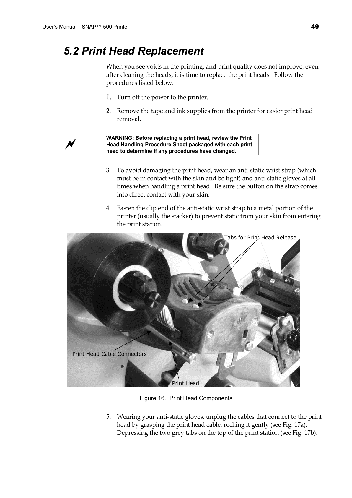
Tabs for Print Head Release
Print Head Cable Connectors
Print Head
Figure 16. Print Head Components
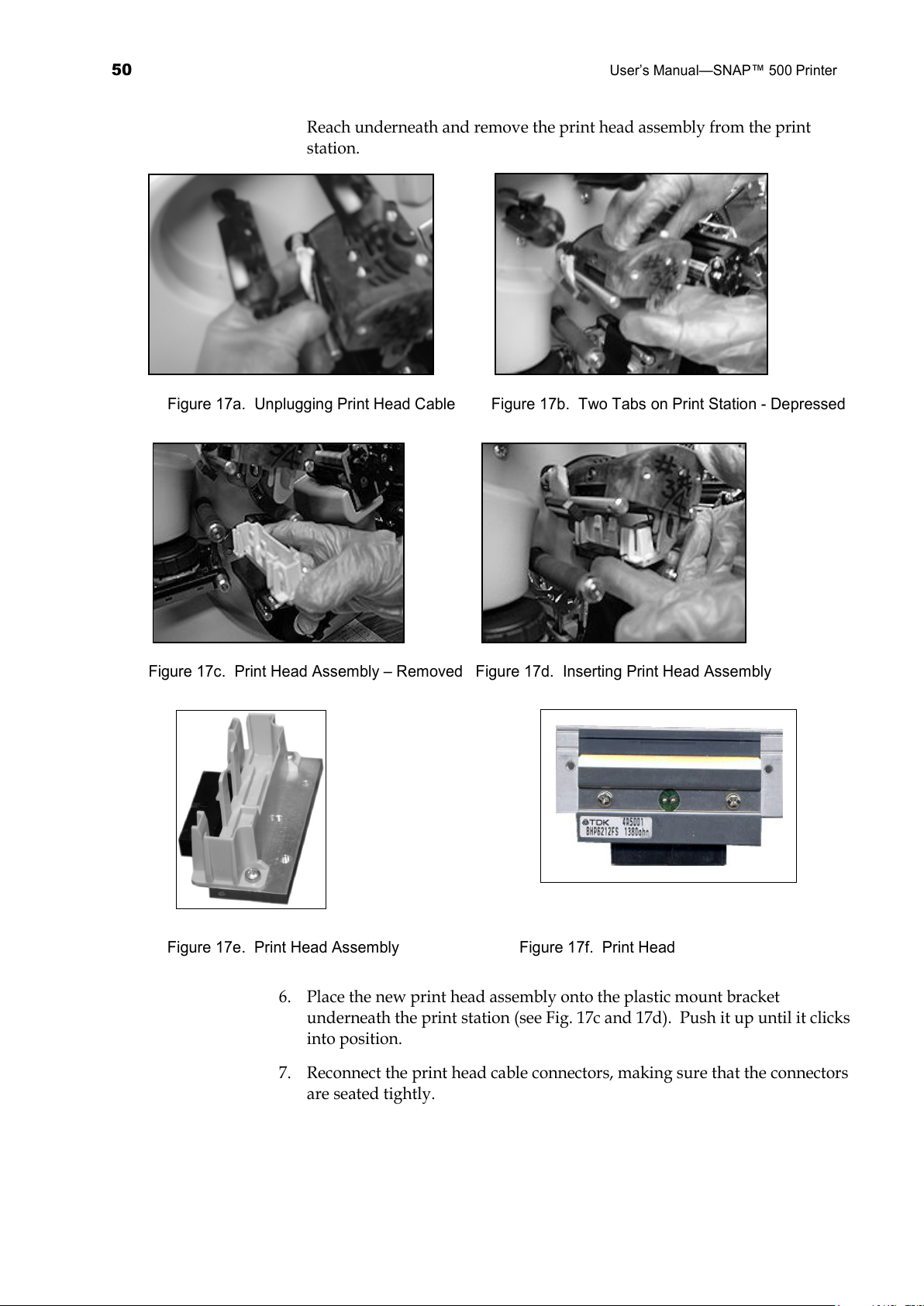
5. Wearing your anti-static gloves, unplug the cables that connect to the print
head by grasping the print head cable, rocking it gently (see Fig. 17a).
Depressing the two grey tabs on the top of the print station (see Fig. 17b).
All manuals and user guides at all-guides.com
Page 50
50
User’s Manual—SNAP™ 500 Printer
Reach underneath and remove the print head assembly from the print
station.
Figure 17a. Unplugging Print Head Cable Figure 17b. Two Tabs on Print Station - Depressed
Figure 17c. Print Head Assembly – Removed Figure 17d. Inserting Print Head Assembly
Figure 17e. Print Head Assembly Figure 17f. Print Head
6. Place the new print head assembly onto the plastic mount bracket
underneath the print station (see Fig. 17c and 17d). Push it up until it clicks
into position.
7. Reconnect the print head cable connectors, making sure that the connectors
are seated tightly.
All manuals and user guides at all-guides.com
Page 51
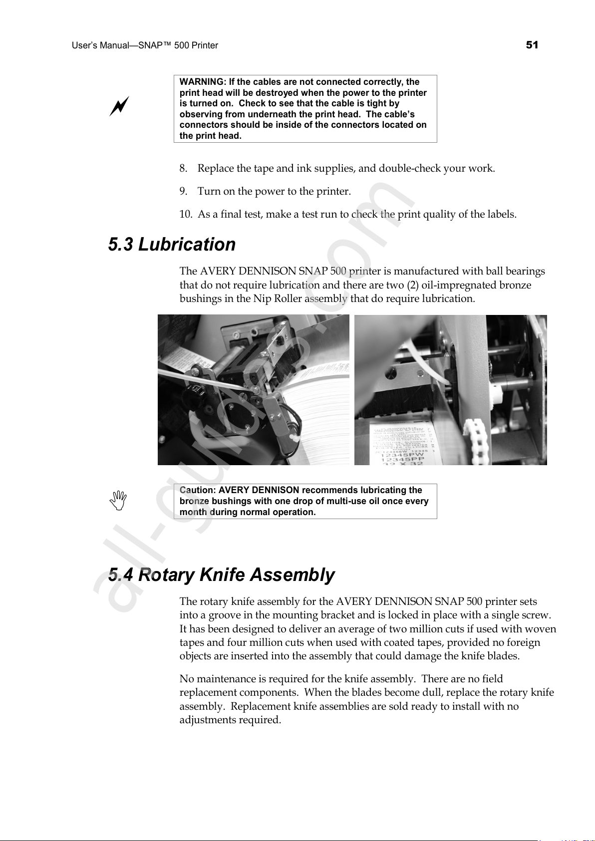
User’s Manual—SNAP™ 500 Printer
51
WARNING: If the cables are not connected correctly, the
print head will be destroyed when the power to the printer
is turned on. Check to see that the cable is tight by
observing from underneath the print head. The cable’s
connectors should be inside of the connectors located on
the print head.
8. Replace the tape and ink supplies, and double-check your work.
9. Turn on the power to the printer.
10. As a final test, make a test run to check the print quality of the labels.
5.3 Lubrication
The AVERY DENNISON SNAP 500 printer is manufactured with ball bearings
that do not require lubrication and there are two (2) oil-impregnated bronze
bushings in the Nip Roller assembly that do require lubrication.
Caution: AVERY DENNISON recommends lubricating the
bronze bushings with one drop of multi-use oil once every
month during normal operation.
5.4 Rotary Knife Assembly
The rotary knife assembly for the AVERY DENNISON SNAP 500 printer sets
into a groove in the mounting bracket and is locked in place with a single screw.
It has been designed to deliver an average of two million cuts if used with woven
tapes and four million cuts when used with coated tapes, provided no foreign
objects are inserted into the assembly that could damage the knife blades.
No maintenance is required for the knife assembly. There are no field
replacement components. When the blades become dull, replace the rotary knife
assembly. Replacement knife assemblies are sold ready to install with no
adjustments required.
All manuals and user guides at all-guides.com
all-guides.com
Page 52
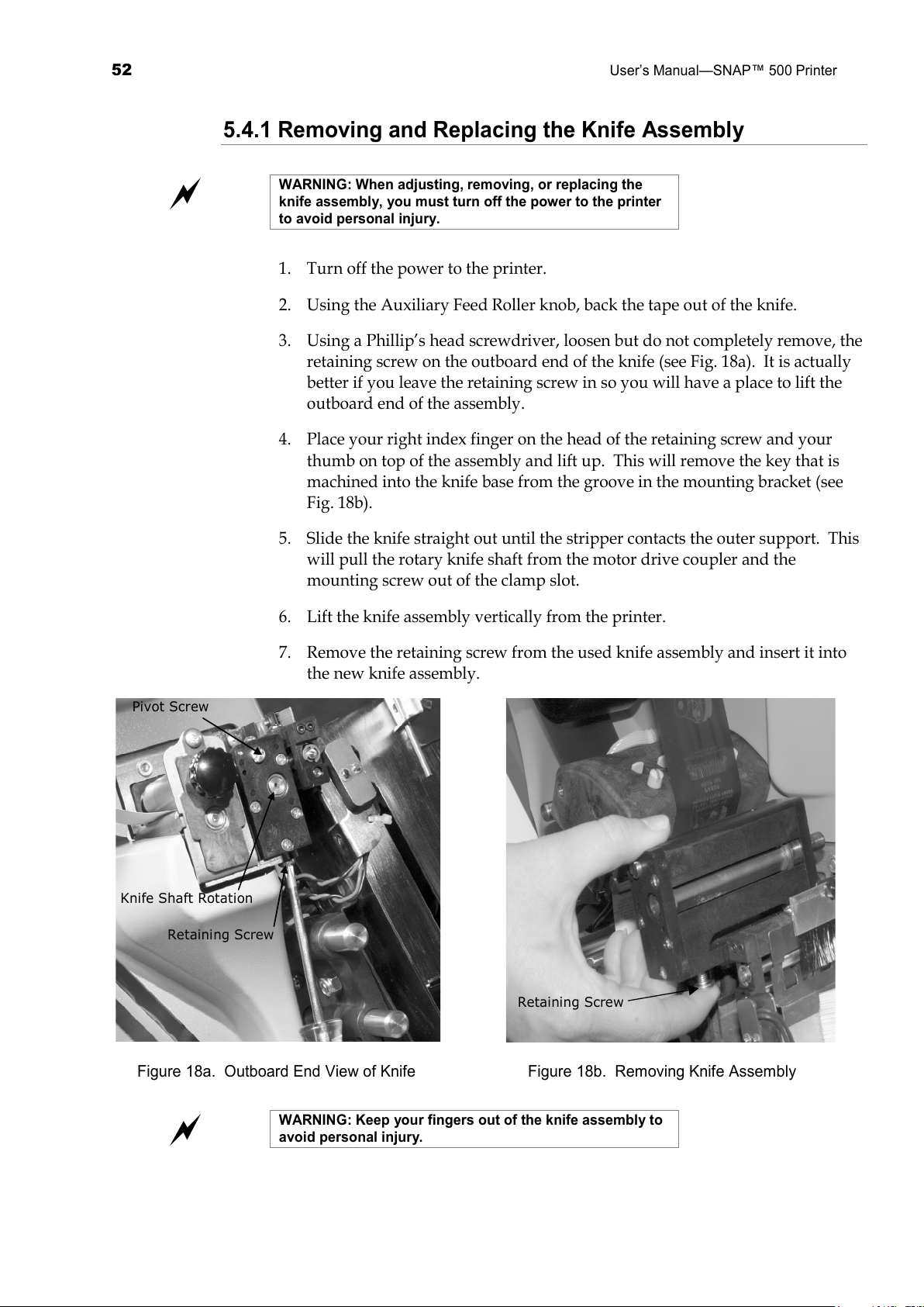
52
User’s Manual—SNAP™ 500 Printer
5.4.1 Removing and Replacing the Knife Assembly
WARNING: When adjusting, removing, or replacing the
knife assembly, you must turn off the power to the printer
to avoid personal injury.
1. Turn off the power to the printer.
2. Using the Auxiliary Feed Roller knob, back the tape out of the knife.
3. Using a Phillip’s head screwdriver, loosen but do not completely remove, the
retaining screw on the outboard end of the knife (see Fig. 18a). It is actually
better if you leave the retaining screw in so you will have a place to lift the
outboard end of the assembly.
4. Place your right index finger on the head of the retaining screw and your
thumb on top of the assembly and lift up. This will remove the key that is
machined into the knife base from the groove in the mounting bracket (see
Fig. 18b).
5. Slide the knife straight out until the stripper contacts the outer support. This
will pull the rotary knife shaft from the motor drive coupler and the
mounting screw out of the clamp slot.
6. Lift the knife assembly vertically from the printer.
7. Remove the retaining screw from the used knife assembly and insert it into
the new knife assembly.
Pivot Screw
Knife Shaft Rotation
Retaining Screw
Retaining Screw
Figure 18a. Outboard End View of Knife Figure 18b. Removing Knife Assembly
WARNING: Keep your fingers out of the knife assembly to
avoid personal injury.
All manuals and user guides at all-guides.com
Page 53

User’s Manual—SNAP™ 500 Printer
53
8. Properly dispose of the used knife assembly.
9. To insert the new knife assembly, slide it down vertically into the space
between the Auxiliary Feed and the Nip Rollers.
10. Hold the knife assembly on the upper outboard corner. Use a flat blade
screwdriver to rotate the rotary knife blade with the screw slot in the knife
until the knife blade slips into the drive shaft.
11. Continue to hold the knife assembly in place. Use a Phillip’s head
screwdriver to retighten the screw.
12. Turn on the power to the printer and allow the knife to return to home
position.
13. Rethread the tape through the Auxiliary Feed, Nip Roller, and knife.
5.4.2 Adjust the Knife Home Position
To adjust the Knife Home Position, follow the procedure listed below.
1. Insert a flat blade screwdriver into the slot in the end of the knife.
2. Rotate the screwdriver counterclockwise until you hear an audible click.
3. Continue to turn the screwdriver approximately 1/8 of a rotation more.
All manuals and user guides at all-guides.com
Page 54
54
User’s Manual—SNAP™ 500 Printer
6.0 Service Adjustments
6.1 Tape (Web) Guide Position
The tape (web) guide is set at the factory to center the tape to the printed image.
If a slight mechanical adjustment is needed, follow these steps.
1. Locate the two screws under the Tape (Web) Guide mount plate.
2. Open the web guides to the widest position by turning the knob above the
guide clockwise.
3. Loosen the two screws.
4. Move the guide to the position desired.
5. Re-tighten the screws.
6.2 Tape (Web) Guide Width Adjustments
Use the knob to move the guides until they touch the edges of the tape.
6.3 Auxiliary Feed
The Auxiliary Feed is the assembly located in front of the knife. It works with
the main feed or the top print roller to maintain proper tension of the tape as it
moves through the printer from the top print station into the Knife and Nip
rollers.
NOTE: The upper print roller must be closed in order for
the tape to feed through the printer.
If the tape will not advance through the Knife, check to be sure the knife is in the
home position (see Sect. 5.4.2, Knife Home Position Adjustment).
6.4 Knife Shear Adjustment
The Knife Assembly in your AVERY DENNISON SNAP 500 printer has no field
replacement components, and basically requires no maintenance or adjustments.
The only adjustment that can be made to the knife in the field is for shear.
WARNING: Knife adjustments procedure must be followed
exactly or damage will occur.
WARNING: When adjusting, removing, or replacing the
knife assembly, you must turn off the power to the printer
to avoid personal injury.
All manuals and user guides at all-guides.com
Page 55
User’s Manual—SNAP™ 500 Printer
55
1. Turn off the power to the printer.
2. Remove the knife assembly from the printer as described in Section 4.4.1. Refer
to Figures 18a and 18b.
3. Loosen the outer pivot screw by making one complete turn (see Fig. 19a).
4. The two setscrews move the stationary outboard end of the knife to increase or
decrease the shear.
5. To increase the shear, loosen the right setscrew ¼ turn (see Fig. 19b) and tighten
the left setscrew (see Fig. 19c).
Pivot Screw
Right Set Screw
Figure 19a. Loosening Outer Pivot Screw Figure 19b. Adjusting Right Set Screw
Left Screw Set
Knife Rotation
Figure 19c. Adjusting Left Set Screw Figure 19d. Manual Rotation of Knife Shaft
6. Re-tighten the outer pivot screw. Screw should be snug but not over tightened.
Over tightening may prevent the upper blade from rotating.
7. Rotate the shaft by hand, using the inboard shaft extending from the assembly
(Fig. 19d). The knife should rotate freely, and will make a metallic shearing
sound during rotation.
8. Insert a strip of the material to be cut so it extends from both sides of the knife.
Test by rotating the knife shaft again to cut the material.
9. If the two parts of the material are still attached by thread, the knife is damaged
and must be replaced.
10. If your test only cuts the material part way through, an additional adjustment is
required.
11. Retest and repeat Steps 9 and 10 above.
All manuals and user guides at all-guides.com
Page 56
56
User’s Manual—SNAP™ 500 Printer
7.0 Remote Control / Display Module
If your AVERY DENNISON SNAP 500 printer is connected to a mainframe
rather than a personal computer, you may use the Remote Control / Display
module (see Figure 20) for various functions. This module serves as a standalone
controller and a printer status display so you can adjust the parameters of your
print runs and observe the current status of the printer. For example, you can
use the remote control / display module to do the following:
• Start and stop the printer.
• Change printer settings, such as the print and cut positions.
• Enable / Disable the knife.
• View the printer status, such as the number of labels printed and cut,
operating system version, and other features within the printer.
• View error messages.
The Remote Control/Display Module can be connected and disconnected from
the printer with the printer on. This allows the use of one module with multiple
printers.
For more information, refer to the Remote Control / Display Module User’s
Manual.
Figure 20. Remote Control / Display Module
All manuals and user guides at all-guides.com
all-guides.com
Page 57
User’s Manual—SNAP™ 500 Printer
57
7.1 Controlling the Printer
As shown in Figure 20, the Remote Control / Display Module has two rows of
buttons. The top row contains the Start, Feed, Test, and Stop buttons. Here is a
brief description of their functions.
• Start—If batches are present, this button initiates printing.
• Feed—This button has no function in the AVERY DENNISON SNAP 500
printer.
• Test – This button has no function in the AVERY DENNISON SNAP 500
printer.
• Stop—Stops the printer.
When you turn on the power to the printer, the message LED says, “Ready for
Batches.” If there are print jobs loaded on the printer, the top line of the LCD
display will say “BATCH ID” and the bottom line will show the Batch ID and the
remaining quantity to be printed.
7.2 The Menu System
The Remote Control / Display Module has a menu system that allows you to
view and change various settings in the printer. See section 4.3 and 4.4 for
details about the settings.
You can enter the menu system by pressing the MODE key. Pressing the MODE
key repeatedly shows the main menu items. When you reach the menu item you
want, press the ENTER key. This starts a sub-menu. You can scroll through the
sub-menus using the Mode key. Pressing the EXIT key turns off the menu
system.
7.3 Changing Values
Settings can be changed in one of three ways:
• If the choices are in the form of a list, such as Print Speeds, use the Yes
and No keys to scroll back and forth though the choices. When the
display shows the choice you want, press the ENTER key. This accepts
your change and makes it active.
• If the setting is a numerical value, such as the Cut Adjust, use the Yes and
No keys to change the value (Yes decreases the value, No increases the
value). When the setting is correct, press the Enter key. In most cases,
the current value is shown on the left of the display and the new value on
the right. When you press the Enter key, the current value will change.
• If the setting has multiple digits, such as the date or time, the left-most
digit will be flashing. Use the Yes and No keys to change the value, then
press Enter. The next digit will begin to flash. Continue until the value is
All manuals and user guides at all-guides.com
Page 58

58
User’s Manual—SNAP™ 500 Printer
correct, then press either the MODE key (to go on to the next menu entry)
or EXIT to exit the menu system.
All manuals and user guides at all-guides.com
Page 59
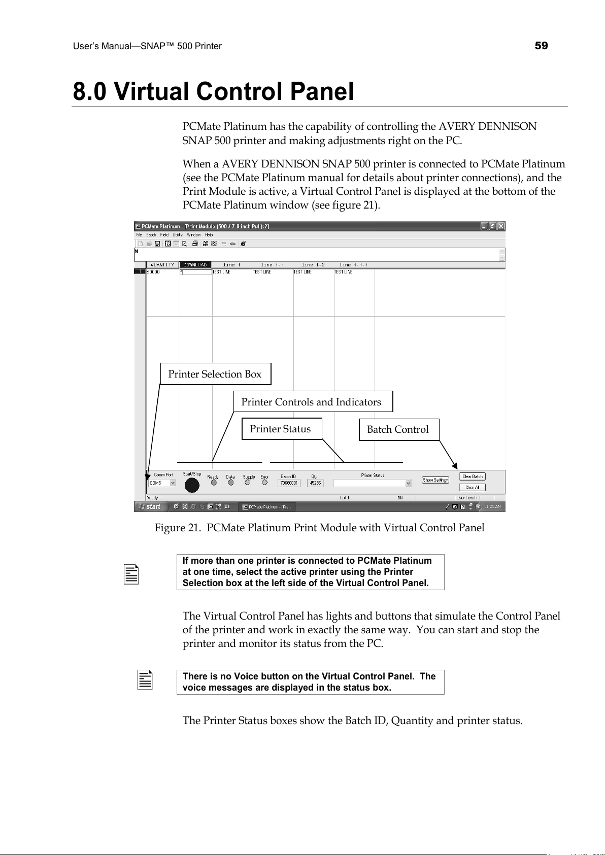
User’s Manual—SNAP™ 500 Printer
59
8.0 Virtual Control Panel
PCMate Platinum has the capability of controlling the AVERY DENNISON
SNAP 500 printer and making adjustments right on the PC.
When a AVERY DENNISON SNAP 500 printer is connected to PCMate Platinum
(see the PCMate Platinum manual for details about printer connections), and the
Print Module is active, a Virtual Control Panel is displayed at the bottom of the
PCMate Platinum window (see figure 21).
Figure 21. PCMate Platinum Print Module with Virtual Control Panel
If more than one printer is connected to PCMate Platinum
at one time, select the active printer using the Printer
Selection box at the left side of the Virtual Control Panel.
The Virtual Control Panel has lights and buttons that simulate the Control Panel
of the printer and work in exactly the same way. You can start and stop the
printer and monitor its status from the PC.
There is no Voice button on the Virtual Control Panel. The
voice messages are displayed in the status box.
The Printer Status boxes show the Batch ID, Quantity and printer status.
Printer Selection Box
Printer Controls and Indicators
Printer Status
Batch Control
All manuals and user guides at all-guides.com
Page 60
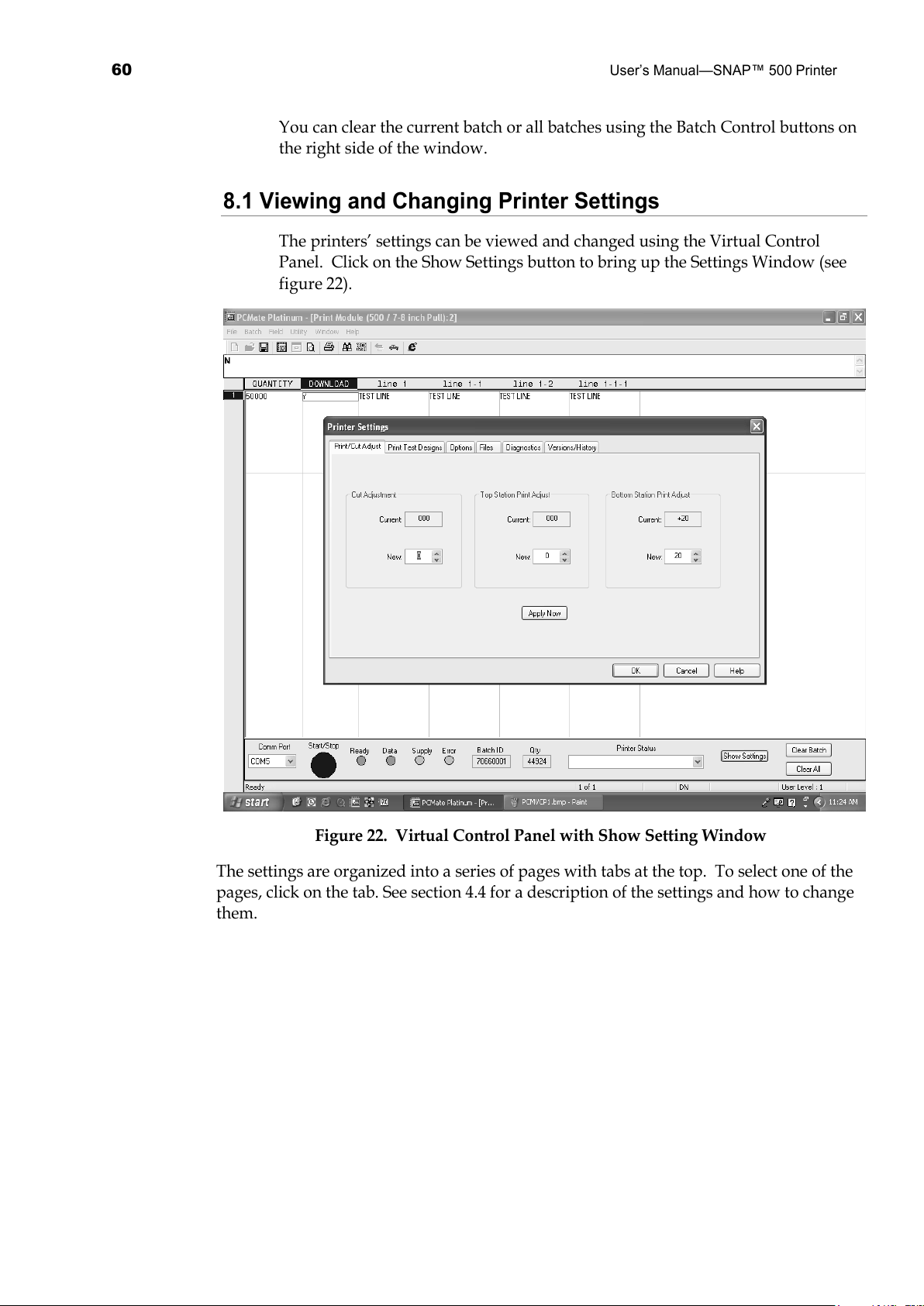
60
User’s Manual—SNAP™ 500 Printer
You can clear the current batch or all batches using the Batch Control buttons on
the right side of the window.
8.1 Viewing and Changing Printer Settings
The printers’ settings can be viewed and changed using the Virtual Control
Panel. Click on the Show Settings button to bring up the Settings Window (see
figure 22).
Figure 22. Virtual Control Panel with Show Setting Window
The settings are organized into a series of pages with tabs at the top. To select one of the
pages, click on the tab. See section 4.4 for a description of the settings and how to change
them.
All manuals and user guides at all-guides.com
Page 61
User’s Manual—SNAP™ 500 Printer
61
9.0 Upgrading the Printer Software
9.1 Introduction
The AVERY DENNISON SNAP 500 printer software can be updated
electronically. Software upgrades are distributed as a single file called the
upgrade or UPG file. PCMate Platinum will take the UPG file and automatically
upgrade the printer. Once the upgrade process is started, no other action is
required.
9.2 What is Needed
The upgrade can only be performed by PCMate Platinum. Therefore, you must
have a Microsoft PC running PCMate Platinum to upgrade the printer software.
See Section 2.1.3 for the minimum requirements to run PCMate Platinum.
9.3 Getting the UPG file
9.3.1 Using SpecStar to get the UPG file
The easiest way to get the upgrade file is through SpecStar. (Contact your
AVERY DENNISON Sales representative for information about SpecStar). If you
have a SpecStar account, contact your SpecStar Coordinator and request that an
upgrade be scheduled for your account. Once this is done, log onto SpecStar,
select In Plant, then Retrieve Updates. The upgrade file will be automatically put
on your PC, and the next time you start up PCMate, it will offer to upgrade the
printer.
9.3.2 Ordering the UPG file on CD
You can order the upgrade file on CD. Contact Customer Service and order part
number 05800327. When you receive the CD, copy the UPG file on the CD to the
C:\D2Comm\Control folder on the PC that is connected to the printer. The next
time you start PCMate Platinum, it will offer to upgrade the printer.
9.4 Getting Ready to Upgrade the Printer
In order to perform the upgrade, the printer must be turned on and connected to
PCMate Platinum. Refer to the PCMate Platinum manual for instructions on
connecting the printer.
9.5 Performing the Upgrade
Start PCMate Platinum. The following screen will appear.
All manuals and user guides at all-guides.com
all-guides.com
Page 62
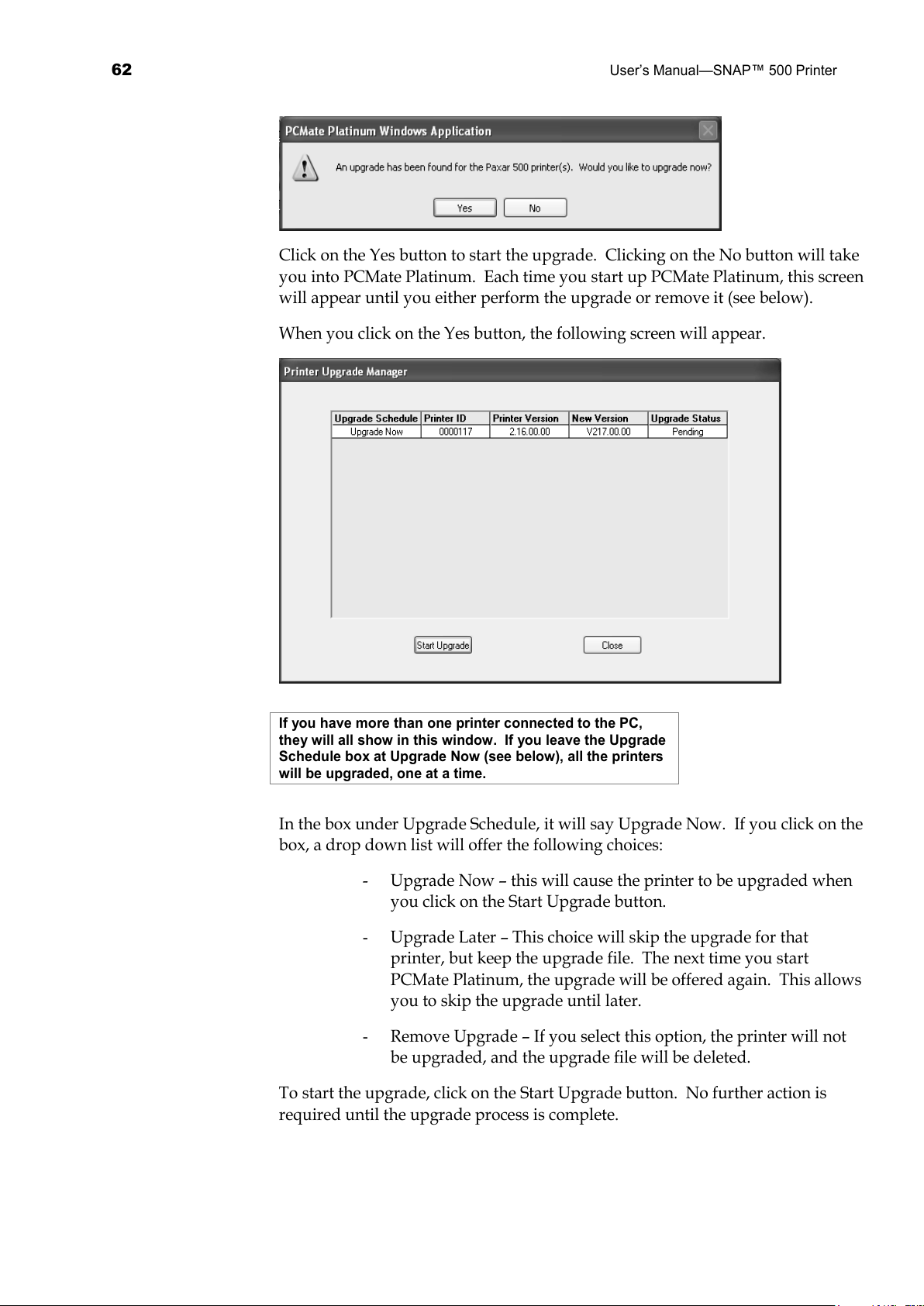
62
User’s Manual—SNAP™ 500 Printer
Click on the Yes button to start the upgrade. Clicking on the No button will take
you into PCMate Platinum. Each time you start up PCMate Platinum, this screen
will appear until you either perform the upgrade or remove it (see below).
When you click on the Yes button, the following screen will appear.
If you have more than one printer connected to the PC,
they will all show in this window. If you leave the Upgrade
Schedule box at Upgrade Now (see below), all the printers
will be upgraded, one at a time.
In the box under Upgrade Schedule, it will say Upgrade Now. If you click on the
box, a drop down list will offer the following choices:
- Upgrade Now – this will cause the printer to be upgraded when
you click on the Start Upgrade button.
- Upgrade Later – This choice will skip the upgrade for that
printer, but keep the upgrade file. The next time you start
PCMate Platinum, the upgrade will be offered again. This allows
you to skip the upgrade until later.
- Remove Upgrade – If you select this option, the printer will not
be upgraded, and the upgrade file will be deleted.
To start the upgrade, click on the Start Upgrade button. No further action is
required until the upgrade process is complete.
All manuals and user guides at all-guides.com
Page 63
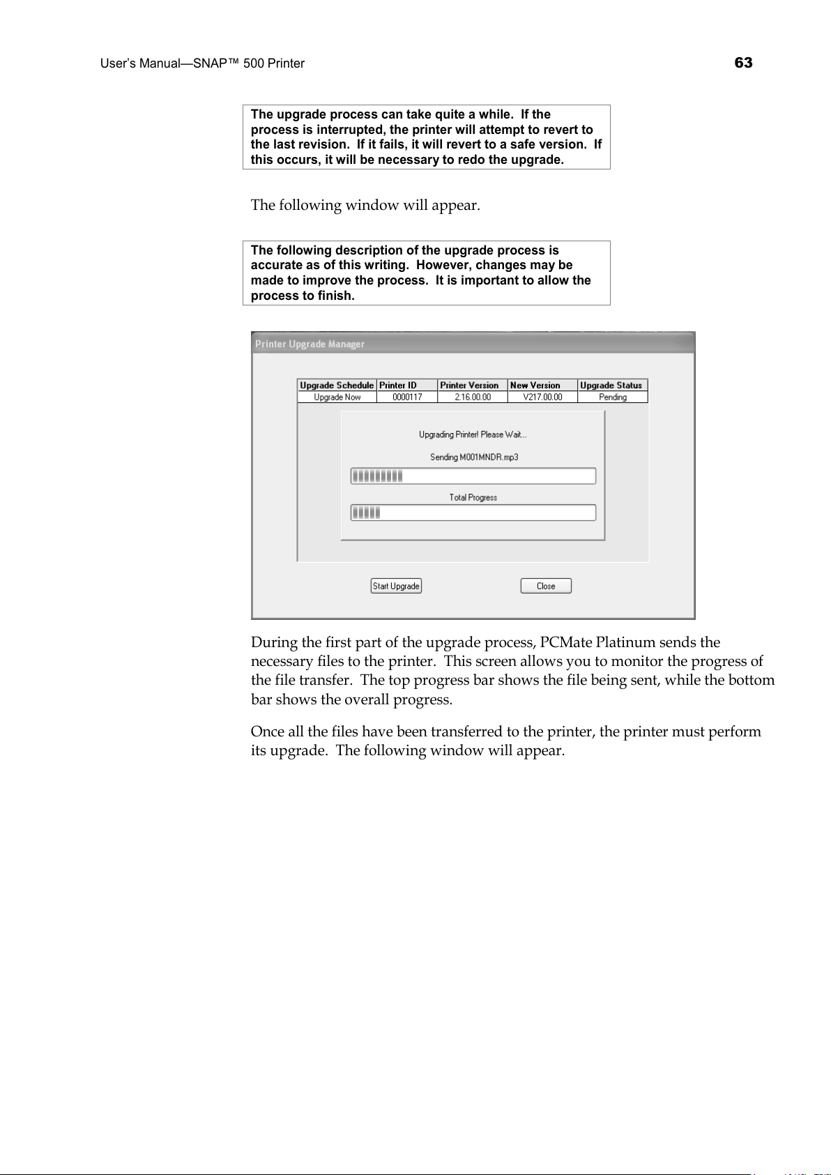
User’s Manual—SNAP™ 500 Printer
63
The upgrade process can take quite a while. If the
process is interrupted, the printer will attempt to revert to
the last revision. If it fails, it will revert to a safe version. If
this occurs, it will be necessary to redo the upgrade.
The following window will appear.
The following description of the upgrade process is
accurate as of this writing. However, changes may be
made to improve the process. It is important to allow the
process to finish.
During the first part of the upgrade process, PCMate Platinum sends the
necessary files to the printer. This screen allows you to monitor the progress of
the file transfer. The top progress bar shows the file being sent, while the bottom
bar shows the overall progress.
Once all the files have been transferred to the printer, the printer must perform
its upgrade. The following window will appear.
All manuals and user guides at all-guides.com
Page 64
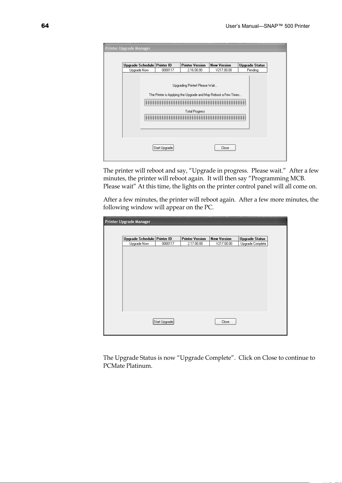
64
User’s Manual—SNAP™ 500 Printer
The printer will reboot and say, “Upgrade in progress. Please wait.” After a few
minutes, the printer will reboot again. It will then say “Programming MCB.
Please wait” At this time, the lights on the printer control panel will all come on.
After a few minutes, the printer will reboot again. After a few more minutes, the
following window will appear on the PC.
The Upgrade Status is now “Upgrade Complete”. Click on Close to continue to
PCMate Platinum.
All manuals and user guides at all-guides.com
Page 65
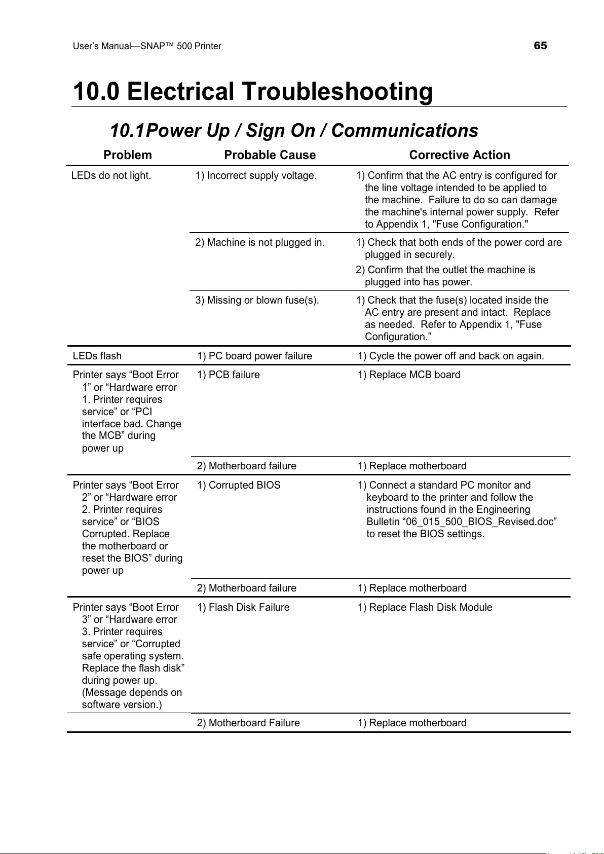
User’s Manual—SNAP™ 500 Printer
65
10.0 Electrical Troubleshooting
10.1 Power Up / Sign On / Communications
Problem Probable Cause Corrective Action
LEDs do not light. 1) Incorrect supply voltage. 1) Confirm that the AC entry is configured for
the line voltage intended to be applied to
the machine. Failure to do so can damage
the machine's internal power supply. Refer
to Appendix 1, "Fuse Configuration."
2) Machine is not plugged in. 1) Check that both ends of the power cord are
plugged in securely.
2) Confirm that the outlet the machine is
plugged into has power.
3) Missing or blown fuse(s). 1) Check that the fuse(s) located inside the
AC entry are present and intact. Replace
as needed. Refer to Appendix 1, "Fuse
Configuration.”
LEDs flash 1) PC board power failure 1) Cycle the power off and back on again.
Printer says “Boot Error
1” or “Hardware error
1. Printer requires
service” or “PCI
interface bad. Change
the MCB” during
power up
1) PCB failure 1) Replace MCB board
2) Motherboard failure 1) Replace motherboard
Printer says “Boot Error
2” or “Hardware error
2. Printer requires
service” or “BIOS
Corrupted. Replace
the motherboard or
reset the BIOS” during
power up
1) Corrupted BIOS 1) Connect a standard PC monitor and
keyboard to the printer and follow the
instructions found in the Engineering
Bulletin “06_015_500_BIOS_Revised.doc”
to reset the BIOS settings.
2) Motherboard failure 1) Replace motherboard
Printer says “Boot Error
3” or “Hardware error
3. Printer requires
service” or “Corrupted
safe operating system.
Replace the flash disk”
during power up.
(Message depends on
software version.)
1) Flash Disk Failure 1) Replace Flash Disk Module
2) Motherboard Failure 1) Replace motherboard
All manuals and user guides at all-guides.com
Page 66
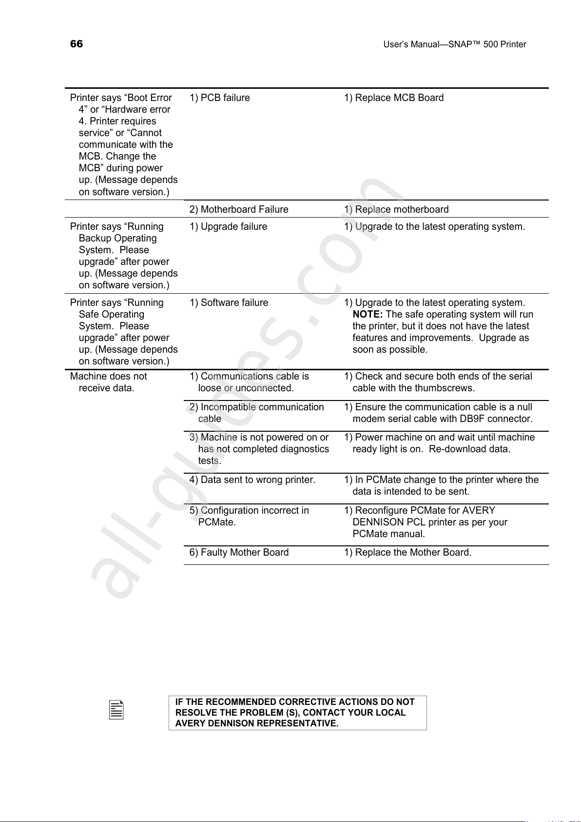
66
User’s Manual—SNAP™ 500 Printer
Printer says “Boot Error
4” or “Hardware error
4. Printer requires
service” or “Cannot
communicate with the
MCB. Change the
MCB” during power
up. (Message depends
on software version.)
1) PCB failure 1) Replace MCB Board
2) Motherboard Failure 1) Replace motherboard
Printer says “Running
Backup Operating
System. Please
upgrade” after power
up. (Message depends
on software version.)
1) Upgrade failure 1) Upgrade to the latest operating system.
Printer says “Running
Safe Operating
System. Please
upgrade” after power
up. (Message depends
on software version.)
1) Software failure 1) Upgrade to the latest operating system.
NOTE: The safe operating system will run
the printer, but it does not have the latest
features and improvements. Upgrade as
soon as possible.
Machine does not
receive data.
1) Communications cable is
loose or unconnected.
1) Check and secure both ends of the serial
cable with the thumbscrews.
2) Incompatible communication
cable
1) Ensure the communication cable is a null
modem serial cable with DB9F connector.
3) Machine is not powered on or
has not completed diagnostics
tests.
1) Power machine on and wait until machine
ready light is on. Re-download data.
4) Data sent to wrong printer. 1) In PCMate change to the printer where the
data is intended to be sent.
5) Configuration incorrect in
PCMate.
1) Reconfigure PCMate for AVERY
DENNISON PCL printer as per your
PCMate manual.
6) Faulty Mother Board 1) Replace the Mother Board.
IF THE RECOMMENDED CORRECTIVE ACTIONS DO NOT
RESOLVE THE PROBLEM (S), CONTACT YOUR LOCAL
AVERY DENNISON REPRESENTATIVE.
All manuals and user guides at all-guides.com
all-guides.com
Page 67
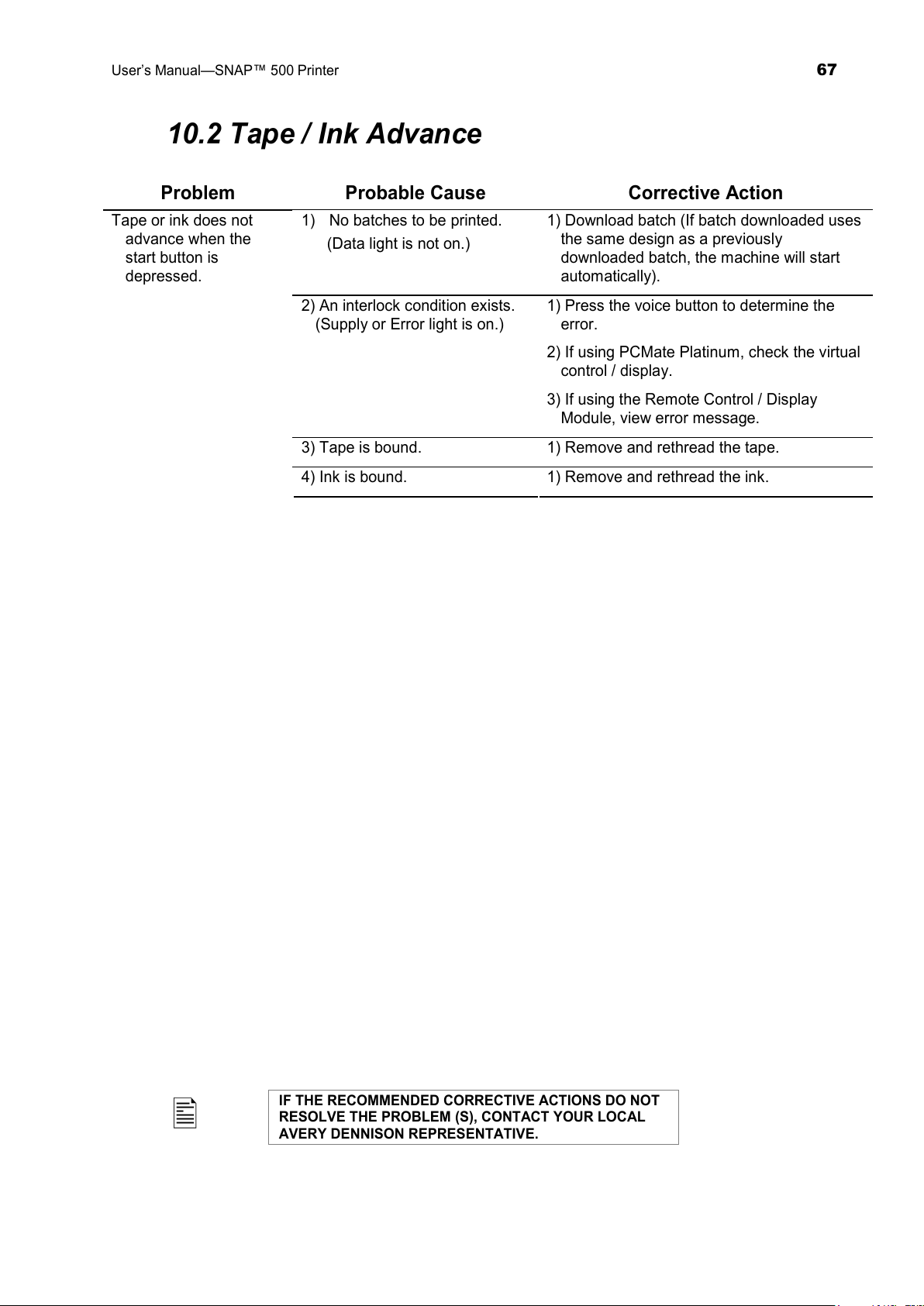
User’s Manual—SNAP™ 500 Printer
67
10.2 Tape / Ink Advance
Problem Probable Cause Corrective Action
Tape or ink does not
advance when the
start button is
depressed.
1) No batches to be printed.
(Data light is not on.)
1) Download batch (If batch downloaded uses
the same design as a previously
downloaded batch, the machine will start
automatically).
2) An interlock condition exists.
(Supply or Error light is on.)
1) Press the voice button to determine the
error.
2) If using PCMate Platinum, check the virtual
control / display.
3) If using the Remote Control / Display
Module, view error message.
3) Tape is bound. 1) Remove and rethread the tape.
4) Ink is bound. 1) Remove and rethread the ink.
IF THE RECOMMENDED CORRECTIVE ACTIONS DO NOT
RESOLVE THE PROBLEM (S), CONTACT YOUR LOCAL
AVERY DENNISON REPRESENTATIVE.
All manuals and user guides at all-guides.com
Page 68
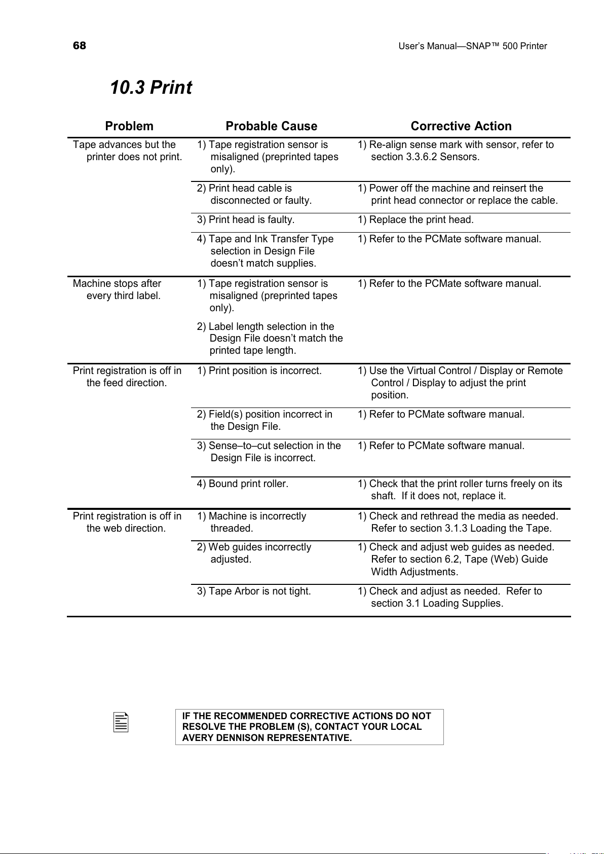
68
User’s Manual—SNAP™ 500 Printer
10.3 Print
Problem Probable Cause Corrective Action
Tape advances but the
printer does not print.
1) Tape registration sensor is
misaligned (preprinted tapes
only).
1) Re-align sense mark with sensor, refer to
section 3.3.6.2 Sensors.
2) Print head cable is
disconnected or faulty.
1) Power off the machine and reinsert the
print head connector or replace the cable.
3) Print head is faulty. 1) Replace the print head.
4) Tape and Ink Transfer Type
selection in Design File
doesn’t match supplies.
1) Refer to the PCMate software manual.
Machine stops after
every third label.
1) Tape registration sensor is
misaligned (preprinted tapes
only).
2) Label length selection in the
Design File doesn’t match the
printed tape length.
1) Refer to the PCMate software manual.
Print registration is off in
the feed direction.
1) Print position is incorrect. 1) Use the Virtual Control / Display or Remote
Control / Display to adjust the print
position.
2) Field(s) position incorrect in
the Design File.
1) Refer to PCMate software manual.
3) Sense–to–cut selection in the
Design File is incorrect.
1) Refer to PCMate software manual.
4) Bound print roller. 1) Check that the print roller turns freely on its
shaft. If it does not, replace it.
Print registration is off in
the web direction.
1) Machine is incorrectly
threaded.
1) Check and rethread the media as needed.
Refer to section 3.1.3 Loading the Tape.
2) Web guides incorrectly
adjusted.
1) Check and adjust web guides as needed.
Refer to section 6.2, Tape (Web) Guide
Width Adjustments.
3) Tape Arbor is not tight. 1) Check and adjust as needed. Refer to
section 3.1 Loading Supplies.
IF THE RECOMMENDED CORRECTIVE ACTIONS DO NOT
RESOLVE THE PROBLEM (S), CONTACT YOUR LOCAL
AVERY DENNISON REPRESENTATIVE.
All manuals and user guides at all-guides.com
Page 69
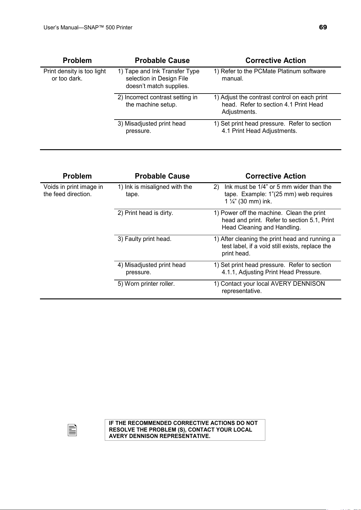
User’s Manual—SNAP™ 500 Printer
69
Problem Probable Cause Corrective Action
Print density is too light
or too dark.
1) Tape and Ink Transfer Type
selection in Design File
doesn’t match supplies.
1) Refer to the PCMate Platinum software
manual.
2) Incorrect contrast setting in
the machine setup.
1) Adjust the contrast control on each print
head. Refer to section 4.1 Print Head
Adjustments.
3) Misadjusted print head
pressure.
1) Set print head pressure. Refer to section
4.1 Print Head Adjustments.
Problem Probable Cause Corrective Action
Voids in print image in
the feed direction.
1) Ink is misaligned with the
tape.
2) Ink must be 1/4” or 5 mm wider than the
tape. Example: 1”(25 mm) web requires
1 ¼” (30 mm) ink.
2) Print head is dirty. 1) Power off the machine. Clean the print
head and print. Refer to section 5.1, Print
Head Cleaning and Handling.
3) Faulty print head. 1) After cleaning the print head and running a
test label, if a void still exists, replace the
print head.
4) Misadjusted print head
pressure.
1) Set print head pressure. Refer to section
4.1.1, Adjusting Print Head Pressure.
5) Worn printer roller. 1) Contact your local AVERY DENNISON
representative.
IF THE RECOMMENDED CORRECTIVE ACTIONS DO NOT
RESOLVE THE PROBLEM (S), CONTACT YOUR LOCAL
AVERY DENNISON REPRESENTATIVE.
All manuals and user guides at all-guides.com
Page 70
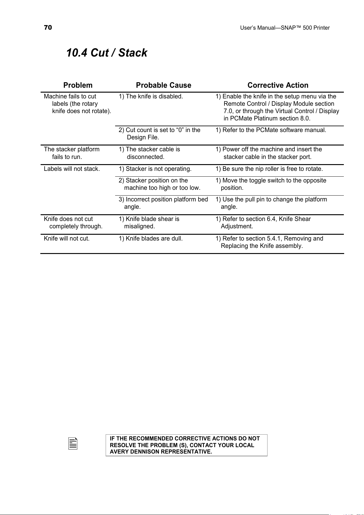
70
User’s Manual—SNAP™ 500 Printer
10.4 Cut / Stack
Problem Probable Cause Corrective Action
Machine fails to cut
labels (the rotary
knife does not rotate).
1) The knife is disabled. 1) Enable the knife in the setup menu via the
Remote Control / Display Module section
7.0, or through the Virtual Control / Display
in PCMate Platinum section 8.0.
2) Cut count is set to “0” in the
Design File.
1) Refer to the PCMate software manual.
The stacker platform
fails to run.
1) The stacker cable is
disconnected.
1) Power off the machine and insert the
stacker cable in the stacker port.
Labels will not stack. 1) Stacker is not operating. 1) Be sure the nip roller is free to rotate.
2) Stacker position on the
machine too high or too low.
1) Move the toggle switch to the opposite
position.
3) Incorrect position platform bed
angle.
1) Use the pull pin to change the platform
angle.
Knife does not cut
completely through.
1) Knife blade shear is
misaligned.
1) Refer to section 6.4, Knife Shear
Adjustment.
Knife will not cut. 1) Knife blades are dull. 1) Refer to section 5.4.1, Removing and
Replacing the Knife assembly.
IF THE RECOMMENDED CORRECTIVE ACTIONS DO NOT
RESOLVE THE PROBLEM (S), CONTACT YOUR LOCAL
AVERY DENNISON REPRESENTATIVE.
All manuals and user guides at all-guides.com
Page 71
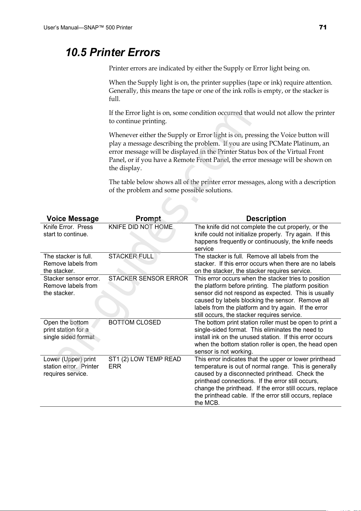
User’s Manual—SNAP™ 500 Printer
71
10.5 Printer Errors
Printer errors are indicated by either the Supply or Error light being on.
When the Supply light is on, the printer supplies (tape or ink) require attention.
Generally, this means the tape or one of the ink rolls is empty, or the stacker is
full.
If the Error light is on, some condition occurred that would not allow the printer
to continue printing.
Whenever either the Supply or Error light is on, pressing the Voice button will
play a message describing the problem. If you are using PCMate Platinum, an
error message will be displayed in the Printer Status box of the Virtual Front
Panel, or if you have a Remote Front Panel, the error message will be shown on
the display.
The table below shows all of the printer error messages, along with a description
of the problem and some possible solutions.
Voice Message Prompt Description
Knife Error. Press
start to continue.
KNIFE DID NOT HOME The knife did not complete the cut properly, or the
knife could not initialize properly. Try again. If this
happens frequently or continuously, the knife needs
service
The stacker is full.
Remove labels from
the stacker.
STACKER FULL The stacker is full. Remove all labels from the
stacker. If this error occurs when there are no labels
on the stacker, the stacker requires service.
Stacker sensor error.
Remove labels from
the stacker.
STACKER SENSOR ERROR This error occurs when the stacker tries to position
the platform before printing. The platform position
sensor did not respond as expected. This is usually
caused by labels blocking the sensor. Remove all
labels from the platform and try again. If the error
still occurs, the stacker requires service.
Open the bottom
print station for a
single sided format
BOTTOM CLOSED The bottom print station roller must be open to print a
single-sided format. This eliminates the need to
install ink on the unused station. If this error occurs
when the bottom station roller is open, the head open
sensor is not working.
Lower (Upper) print
station error. Printer
requires service.
ST1 (2) LOW TEMP READ
ERR
This error indicates that the upper or lower printhead
temperature is out of normal range. This is generally
caused by a disconnected printhead. Check the
printhead connections. If the error still occurs,
change the printhead. If the error still occurs, replace
the printhead cable. If the error still occurs, replace
the MCB.
All manuals and user guides at all-guides.com
all-guides.com
Page 72
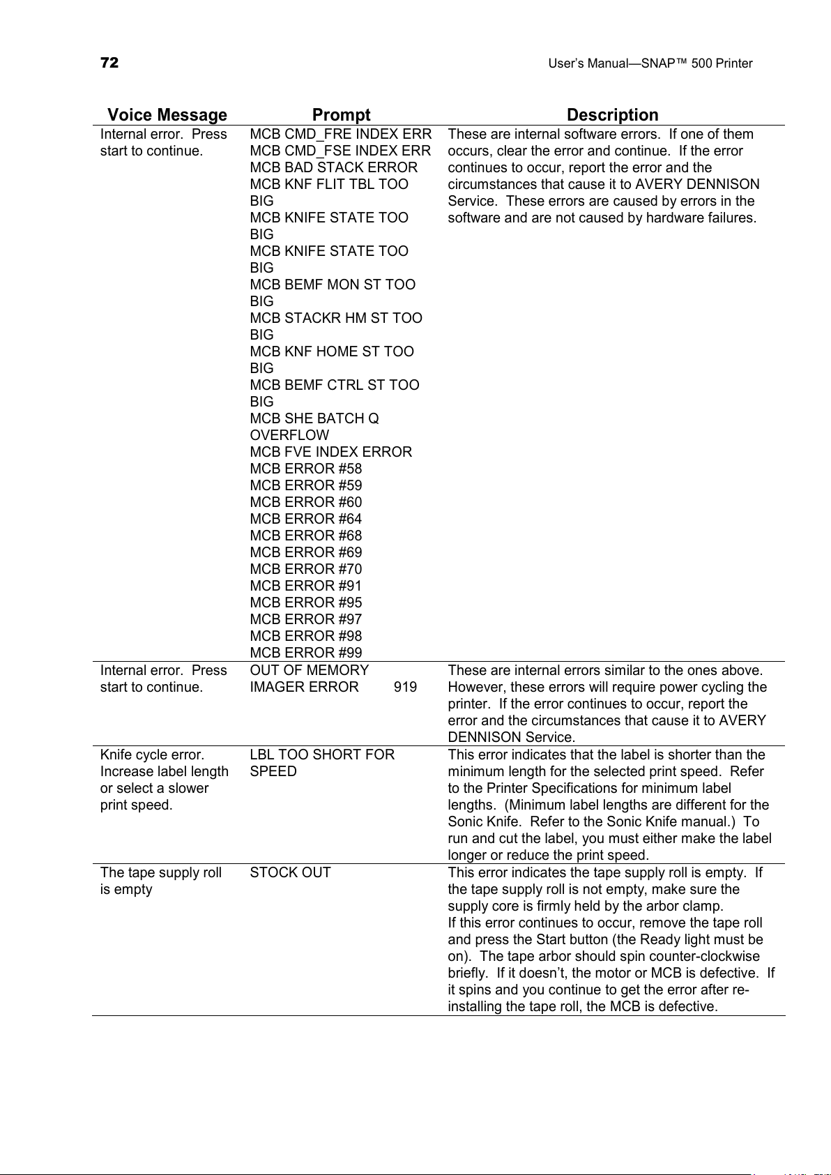
72
User’s Manual—SNAP™ 500 Printer
Voice Message Prompt Description
Internal error. Press
start to continue.
MCB CMD_FRE INDEX ERR
MCB CMD_FSE INDEX ERR
MCB BAD STACK ERROR
MCB KNF FLIT TBL TOO
BIG
MCB KNIFE STATE TOO
BIG
MCB KNIFE STATE TOO
BIG
MCB BEMF MON ST TOO
BIG
MCB STACKR HM ST TOO
BIG
MCB KNF HOME ST TOO
BIG
MCB BEMF CTRL ST TOO
BIG
MCB SHE BATCH Q
OVERFLOW
MCB FVE INDEX ERROR
MCB ERROR #58
MCB ERROR #59
MCB ERROR #60
MCB ERROR #64
MCB ERROR #68
MCB ERROR #69
MCB ERROR #70
MCB ERROR #91
MCB ERROR #95
MCB ERROR #97
MCB ERROR #98
MCB ERROR #99
These are internal software errors. If one of them
occurs, clear the error and continue. If the error
continues to occur, report the error and the
circumstances that cause it to AVERY DENNISON
Service. These errors are caused by errors in the
software and are not caused by hardware failures.
Internal error. Press
start to continue.
OUT OF MEMORY
IMAGER ERROR 919
These are internal errors similar to the ones above.
However, these errors will require power cycling the
printer. If the error continues to occur, report the
error and the circumstances that cause it to AVERY
DENNISON Service.
Knife cycle error.
Increase label length
or select a slower
print speed.
LBL TOO SHORT FOR
SPEED
This error indicates that the label is shorter than the
minimum length for the selected print speed. Refer
to the Printer Specifications for minimum label
lengths. (Minimum label lengths are different for the
Sonic Knife. Refer to the Sonic Knife manual.) To
run and cut the label, you must either make the label
longer or reduce the print speed.
The tape supply roll
is empty
STOCK OUT This error indicates the tape supply roll is empty. If
the tape supply roll is not empty, make sure the
supply core is firmly held by the arbor clamp.
If this error continues to occur, remove the tape roll
and press the Start button (the Ready light must be
on). The tape arbor should spin counter-clockwise
briefly. If it doesn’t, the motor or MCB is defective. If
it spins and you continue to get the error after re-
installing the tape roll, the MCB is defective.
All manuals and user guides at all-guides.com
Page 73
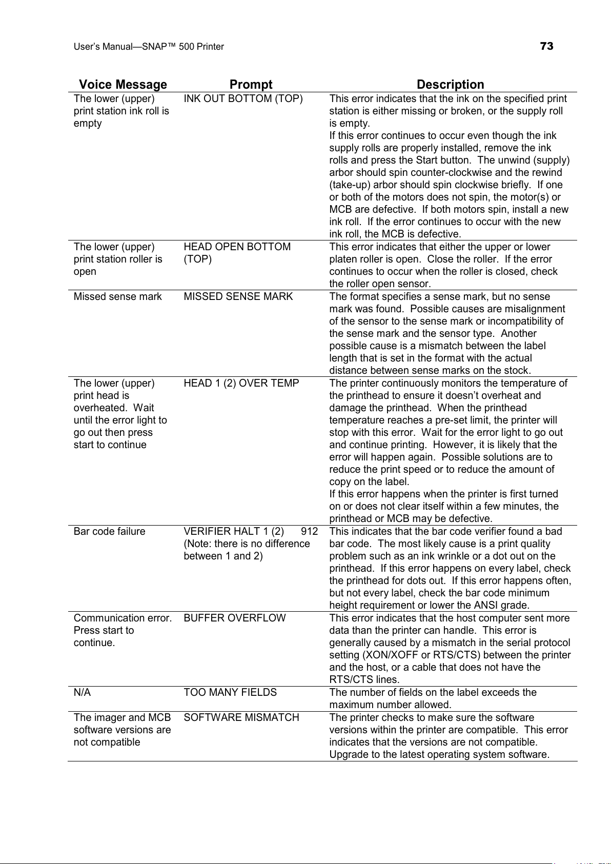
User’s Manual—SNAP™ 500 Printer
73
Voice Message Prompt Description
The lower (upper)
print station ink roll is
empty
INK OUT BOTTOM (TOP) This error indicates that the ink on the specified print
station is either missing or broken, or the supply roll
is empty.
If this error continues to occur even though the ink
supply rolls are properly installed, remove the ink
rolls and press the Start button. The unwind (supply)
arbor should spin counter-clockwise and the rewind
(take-up) arbor should spin clockwise briefly. If one
or both of the motors does not spin, the motor(s) or
MCB are defective. If both motors spin, install a new
ink roll. If the error continues to occur with the new
ink roll, the MCB is defective.
The lower (upper)
print station roller is
open
HEAD OPEN BOTTOM
(TOP)
This error indicates that either the upper or lower
platen roller is open. Close the roller. If the error
continues to occur when the roller is closed, check
the roller open sensor.
Missed sense mark MISSED SENSE MARK The format specifies a sense mark, but no sense
mark was found. Possible causes are misalignment
of the sensor to the sense mark or incompatibility of
the sense mark and the sensor type. Another
possible cause is a mismatch between the label
length that is set in the format with the actual
distance between sense marks on the stock.
The lower (upper)
print head is
overheated. Wait
until the error light to
go out then press
start to continue
HEAD 1 (2) OVER TEMP The printer continuously monitors the temperature of
the printhead to ensure it doesn’t overheat and
damage the printhead. When the printhead
temperature reaches a pre-set limit, the printer will
stop with this error. Wait for the error light to go out
and continue printing. However, it is likely that the
error will happen again. Possible solutions are to
reduce the print speed or to reduce the amount of
copy on the label.
If this error happens when the printer is first turned
on or does not clear itself within a few minutes, the
printhead or MCB may be defective.
Bar code failure VERIFIER HALT 1 (2) 912
(Note: there is no difference
between 1 and 2)
This indicates that the bar code verifier found a bad
bar code. The most likely cause is a print quality
problem such as an ink wrinkle or a dot out on the
printhead. If this error happens on every label, check
the printhead for dots out. If this error happens often,
but not every label, check the bar code minimum
height requirement or lower the ANSI grade.
Communication error.
Press start to
continue.
BUFFER OVERFLOW This error indicates that the host computer sent more
data than the printer can handle. This error is
generally caused by a mismatch in the serial protocol
setting (XON/XOFF or RTS/CTS) between the printer
and the host, or a cable that does not have the
RTS/CTS lines.
N/A TOO MANY FIELDS The number of fields on the label exceeds the
maximum number allowed.
The imager and MCB
software versions are
not compatible
SOFTWARE MISMATCH The printer checks to make sure the software
versions within the printer are compatible. This error
indicates that the versions are not compatible.
Upgrade to the latest operating system software.
All manuals and user guides at all-guides.com
Page 74
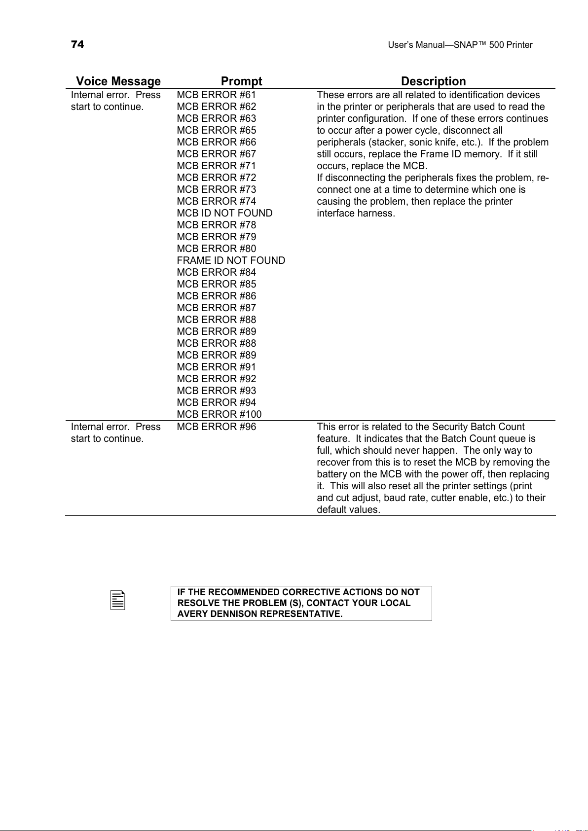
74
User’s Manual—SNAP™ 500 Printer
Voice Message Prompt Description
Internal error. Press
start to continue.
MCB ERROR #61
MCB ERROR #62
MCB ERROR #63
MCB ERROR #65
MCB ERROR #66
MCB ERROR #67
MCB ERROR #71
MCB ERROR #72
MCB ERROR #73
MCB ERROR #74
MCB ID NOT FOUND
MCB ERROR #78
MCB ERROR #79
MCB ERROR #80
FRAME ID NOT FOUND
MCB ERROR #84
MCB ERROR #85
MCB ERROR #86
MCB ERROR #87
MCB ERROR #88
MCB ERROR #89
MCB ERROR #88
MCB ERROR #89
MCB ERROR #91
MCB ERROR #92
MCB ERROR #93
MCB ERROR #94
MCB ERROR #100
These errors are all related to identification devices
in the printer or peripherals that are used to read the
printer configuration. If one of these errors continues
to occur after a power cycle, disconnect all
peripherals (stacker, sonic knife, etc.). If the problem
still occurs, replace the Frame ID memory. If it still
occurs, replace the MCB.
If disconnecting the peripherals fixes the problem, re-
connect one at a time to determine which one is
causing the problem, then replace the printer
interface harness.
Internal error. Press
start to continue.
MCB ERROR #96 This error is related to the Security Batch Count
feature. It indicates that the Batch Count queue is
full, which should never happen. The only way to
recover from this is to reset the MCB by removing the
battery on the MCB with the power off, then replacing
it. This will also reset all the printer settings (print
and cut adjust, baud rate, cutter enable, etc.) to their
default values.
IF THE RECOMMENDED CORRECTIVE ACTIONS DO NOT
RESOLVE THE PROBLEM (S), CONTACT YOUR LOCAL
AVERY DENNISON REPRESENTATIVE.
All manuals and user guides at all-guides.com
Page 75
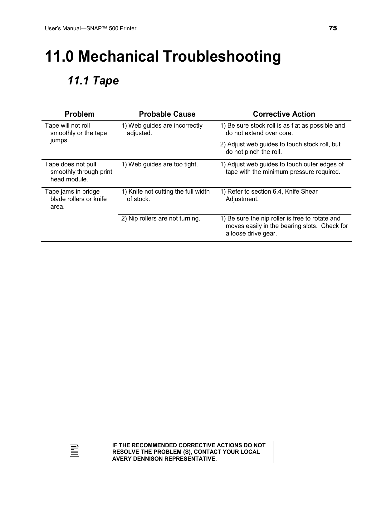
User’s Manual—SNAP™ 500 Printer
75
11.0 Mechanical Troubleshooting
11.1 Tape
Problem Probable Cause Corrective Action
Tape will not roll
smoothly or the tape
jumps.
1) Web guides are incorrectly
adjusted.
1) Be sure stock roll is as flat as possible and
do not extend over core.
2) Adjust web guides to touch stock roll, but
do not pinch the roll.
Tape does not pull
smoothly through print
head module.
1) Web guides are too tight. 1) Adjust web guides to touch outer edges of
tape with the minimum pressure required.
Tape jams in bridge
blade rollers or knife
area.
1) Knife not cutting the full width
of stock.
1) Refer to section 6.4, Knife Shear
Adjustment.
2) Nip rollers are not turning. 1) Be sure the nip roller is free to rotate and
moves easily in the bearing slots. Check for
a loose drive gear.
IF THE RECOMMENDED CORRECTIVE ACTIONS DO NOT
RESOLVE THE PROBLEM (S), CONTACT YOUR LOCAL
AVERY DENNISON REPRESENTATIVE.
All manuals and user guides at all-guides.com
Page 76
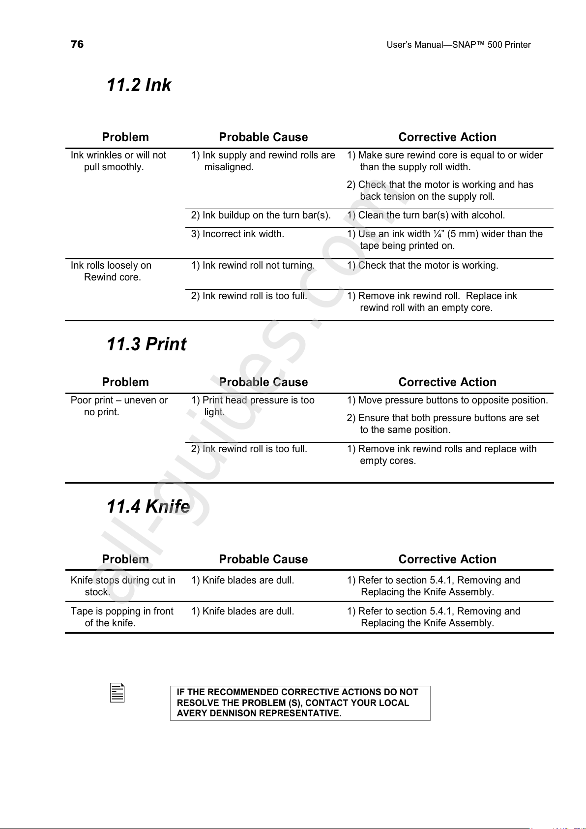
76
User’s Manual—SNAP™ 500 Printer
11.2 Ink
Problem Probable Cause Corrective Action
Ink wrinkles or will not
pull smoothly.
1) Ink supply and rewind rolls are
misaligned.
1) Make sure rewind core is equal to or wider
than the supply roll width.
2) Check that the motor is working and has
back tension on the supply roll.
2) Ink buildup on the turn bar(s). 1) Clean the turn bar(s) with alcohol.
3) Incorrect ink width. 1) Use an ink width ¼” (5 mm) wider than the
tape being printed on.
Ink rolls loosely on
Rewind core.
1) Ink rewind roll not turning. 1) Check that the motor is working.
2) Ink rewind roll is too full. 1) Remove ink rewind roll. Replace ink
rewind roll with an empty core.
11.3 Print
Problem Probable Cause Corrective Action
Poor print – uneven or
no print.
1) Print head pressure is too
light.
1) Move pressure buttons to opposite position.
2) Ensure that both pressure buttons are set
to the same position.
2) Ink rewind roll is too full. 1) Remove ink rewind rolls and replace with
empty cores.
11.4 Knife
Problem Probable Cause Corrective Action
Knife stops during cut in
stock.
1) Knife blades are dull. 1) Refer to section 5.4.1, Removing and
Replacing the Knife Assembly.
Tape is popping in front
of the knife.
1) Knife blades are dull. 1) Refer to section 5.4.1, Removing and
Replacing the Knife Assembly.
IF THE RECOMMENDED CORRECTIVE ACTIONS DO NOT
RESOLVE THE PROBLEM (S), CONTACT YOUR LOCAL
AVERY DENNISON REPRESENTATIVE.
All manuals and user guides at all-guides.com
all-guides.com
Page 77
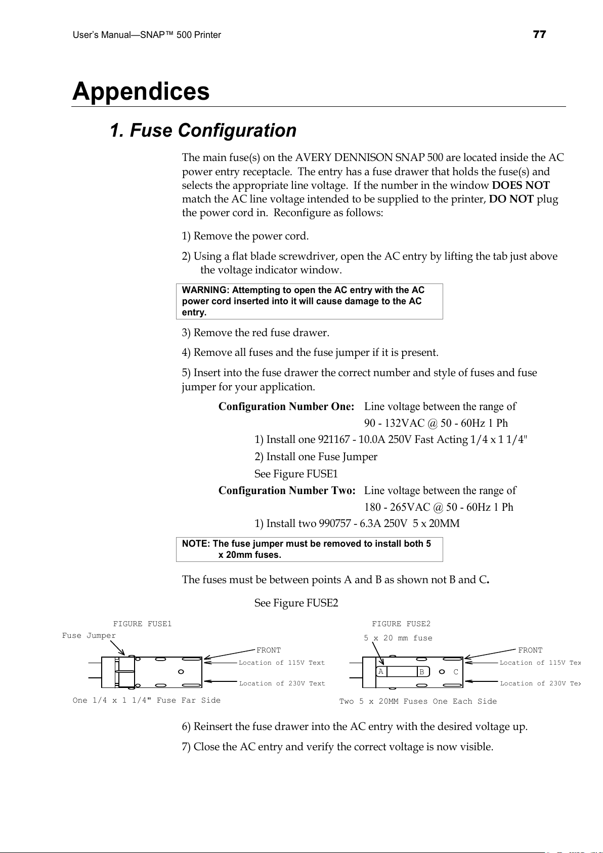
User’s Manual—SNAP™ 500 Printer
77
Appendices
1. Fuse Configuration
The main fuse(s) on the AVERY DENNISON SNAP 500 are located inside the AC
power entry receptacle. The entry has a fuse drawer that holds the fuse(s) and
selects the appropriate line voltage. If the number in the window DOES NOT
match the AC line voltage intended to be supplied to the printer, DO NOT plug
the power cord in. Reconfigure as follows:
1) Remove the power cord.
2) Using a flat blade screwdriver, open the AC entry by lifting the tab just above
the voltage indicator window.
WARNING: Attempting to open the AC entry with the AC
power cord inserted into it will cause damage to the AC
entry.
3) Remove the red fuse drawer.
4) Remove all fuses and the fuse jumper if it is present.
5) Insert into the fuse drawer the correct number and style of fuses and fuse
jumper for your application.
Configuration Number One: Line voltage between the range of
90 - 132VAC @ 50 - 60Hz 1 Ph
1) Install one 921167 - 10.0A 250V Fast Acting 1/4 x 1 1/4"
2) Install one Fuse Jumper
See Figure FUSE1
Configuration Number Two: Line voltage between the range of
180 - 265VAC @ 50 - 60Hz 1 Ph
1) Install two 990757 - 6.3A 250V 5 x 20MM
NOTE: The fuse jumper must be removed to install both 5
x 20mm fuses.
The fuses must be between points A and B as shown not B and C.
See Figure FUSE2
Location of 115V Text
Location of 230V Text
Two 5 x 20MM Fuses One Each Side
FIGURE FUSE2
One 1/4 x 1 1/4" Fuse Far Side
Location of 115V Text
Location of 230V Text
Fuse Jumper
FIGURE FUSE1
5 x 20 mm fuse
FRONT FRONT
A
B
C
6) Reinsert the fuse drawer into the AC entry with the desired voltage up.
7) Close the AC entry and verify the correct voltage is now visible.
All manuals and user guides at all-guides.com
Page 78
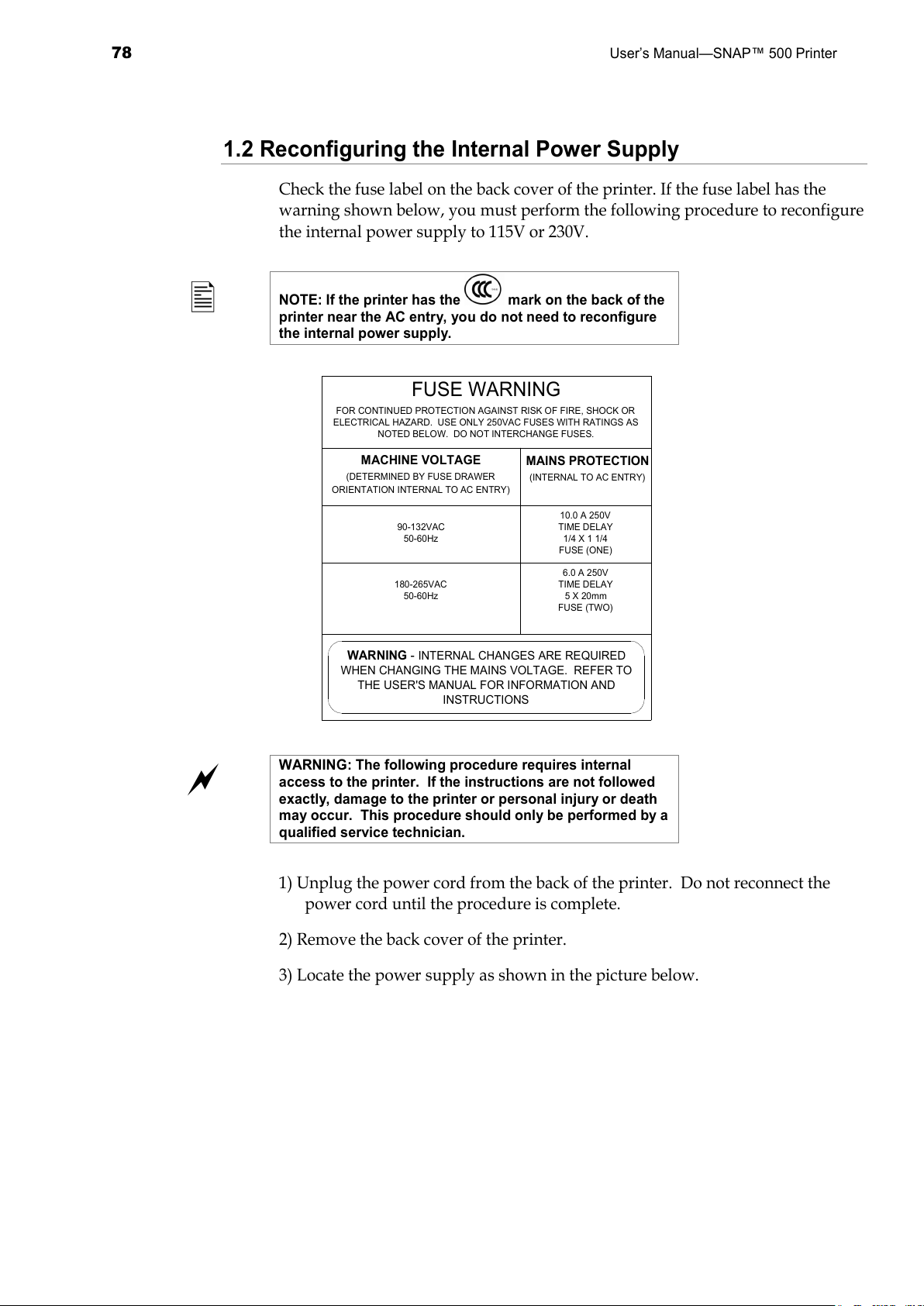
78
User’s Manual—SNAP™ 500 Printer
1.2 Reconfiguring the Internal Power Supply
Check the fuse label on the back cover of the printer. If the fuse label has the
warning shown below, you must perform the following procedure to reconfigure
the internal power supply to 115V or 230V.
NOTE: If the printer has the mark on the back of the
printer near the AC entry, you do not need to reconfigure
the internal power supply.
FUSE WARNING
FOR CONTINUED PROTECTION AGAINST RISK OF FIRE, SHOCK OR
ELECTRICAL HAZARD. USE ONLY 250VAC FUSES WITH RATINGS AS
NOTED BELOW. DO NOT INTERCHANGE FUSES.
MACHINE VOLTAGE
(DETERMINED BY FUSE DRAWER
ORIENTATION INTERNAL TO AC ENTRY)
90-132VAC
50-60Hz
180-265VAC
50-60Hz
MAINS PROTECTION
(INTERNAL TO AC ENTRY)
10.0 A 250V
TIME DELAY
1/4 X 1 1/4
FUSE (ONE)
6.0 A 250V
TIME DELAY
5 X 20mm
FUSE (TWO)
WARNING -
INTERNAL CHANGES ARE REQUIRED
WHEN CHANGING THE MAINS VOLTAGE. REFER TO
THE USER'S MANUAL FOR INFORMATION AND
INSTRUCTIONS
WARNING: The following procedure requires internal
access to the printer. If the instructions are not followed
exactly, damage to the printer or personal injury or death
may occur. This procedure should only be performed by a
qualified service technician.
1) Unplug the power cord from the back of the printer. Do not reconnect the
power cord until the procedure is complete.
2) Remove the back cover of the printer.
3) Locate the power supply as shown in the picture below.
All manuals and user guides at all-guides.com
Page 79
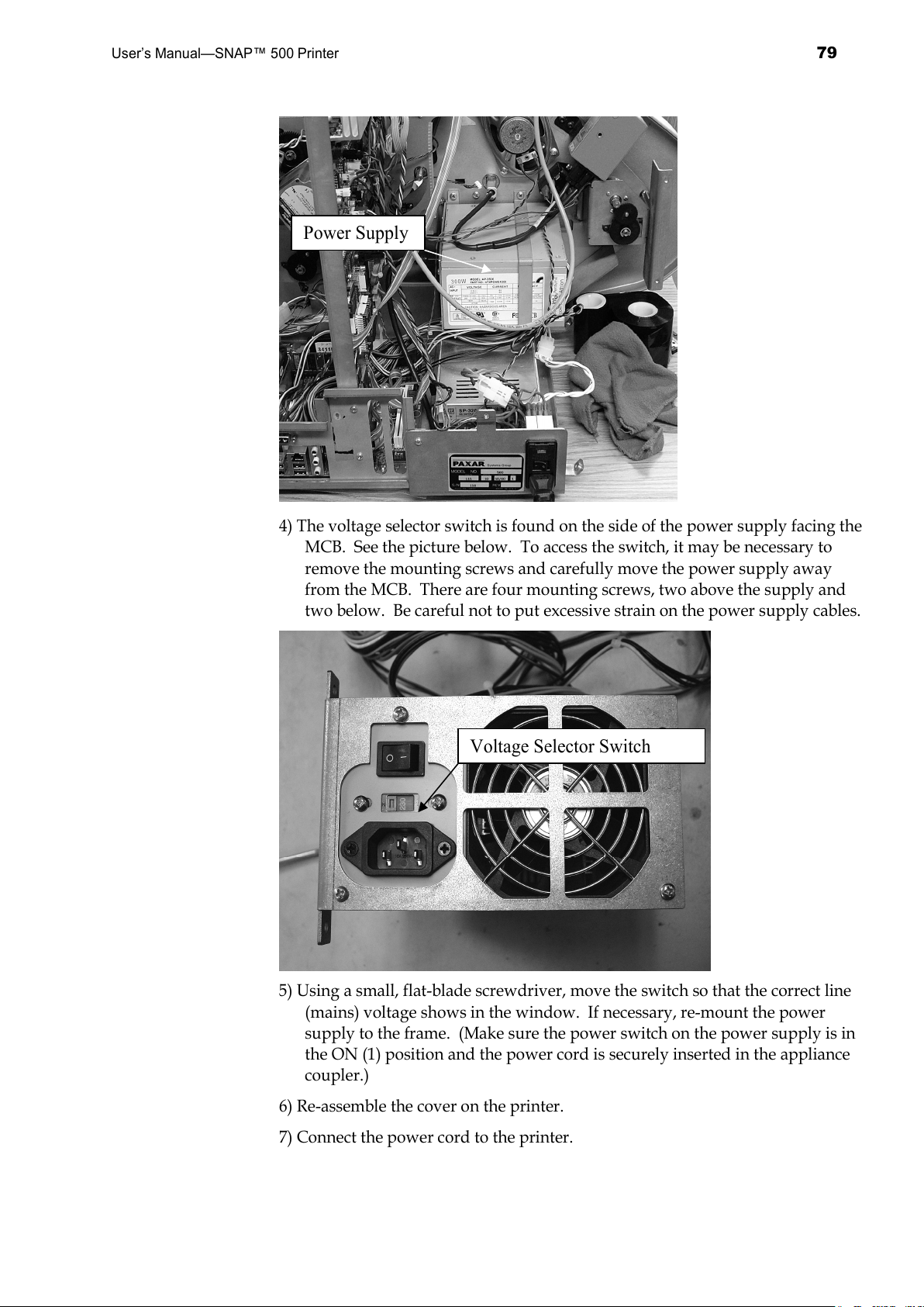
User’s Manual—SNAP™ 500 Printer
79
4) The voltage selector switch is found on the side of the power supply facing the
MCB. See the picture below. To access the switch, it may be necessary to
remove the mounting screws and carefully move the power supply away
from the MCB. There are four mounting screws, two above the supply and
two below. Be careful not to put excessive strain on the power supply cables.
5) Using a small, flat-blade screwdriver, move the switch so that the correct line
(mains) voltage shows in the window. If necessary, re-mount the power
supply to the frame. (Make sure the power switch on the power supply is in
the ON (1) position and the power cord is securely inserted in the appliance
coupler.)
6) Re-assemble the cover on the printer.
7) Connect the power cord to the printer.
Power Supply
Voltage Selector Switch
All manuals and user guides at all-guides.com
Page 80
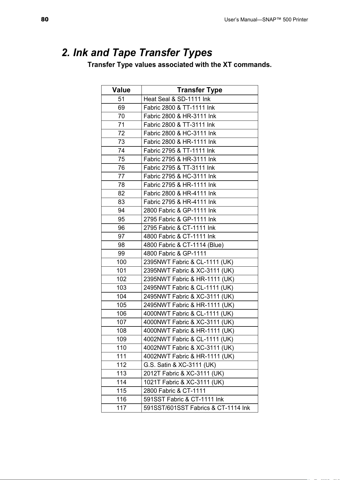
80
User’s Manual—SNAP™ 500 Printer
2. Ink and Tape Transfer Types
Transfer Type values associated with the XT commands.
Value Transfer Type
51 Heat Seal & SD-1111 Ink
69 Fabric 2800 & TT-1111 Ink
70 Fabric 2800 & HR-3111 Ink
71 Fabric 2800 & TT-3111 Ink
72 Fabric 2800 & HC-3111 Ink
73 Fabric 2800 & HR-1111 Ink
74 Fabric 2795 & TT-1111 Ink
75 Fabric 2795 & HR-3111 Ink
76 Fabric 2795 & TT-3111 Ink
77 Fabric 2795 & HC-3111 Ink
78 Fabric 2795 & HR-1111 Ink
82 Fabric 2800 & HR-4111 Ink
83 Fabric 2795 & HR-4111 Ink
94 2800 Fabric & GP-1111 Ink
95 2795 Fabric & GP-1111 Ink
96 2795 Fabric & CT-1111 Ink
97 4800 Fabric & CT-1111 Ink
98 4800 Fabric & CT-1114 (Blue)
99 4800 Fabric & GP-1111
100 2395NWT Fabric & CL-1111 (UK)
101 2395NWT Fabric & XC-3111 (UK)
102 2395NWT Fabric & HR-1111 (UK)
103 2495NWT Fabric & CL-1111 (UK)
104 2495NWT Fabric & XC-3111 (UK)
105 2495NWT Fabric & HR-1111 (UK)
106 4000NWT Fabric & CL-1111 (UK)
107 4000NWT Fabric & XC-3111 (UK)
108 4000NWT Fabric & HR-1111 (UK)
109 4002NWT Fabric & CL-1111 (UK)
110 4002NWT Fabric & XC-3111 (UK)
111 4002NWT Fabric & HR-1111 (UK)
112 G.S. Satin & XC-3111 (UK)
113 2012T Fabric & XC-3111 (UK)
114 1021T Fabric & XC-3111 (UK)
115 2800 Fabric & CT-1111
116 591SST Fabric & CT-1111 Ink
117 591SST/601SST Fabrics & CT-1114 Ink
All manuals and user guides at all-guides.com
Page 81
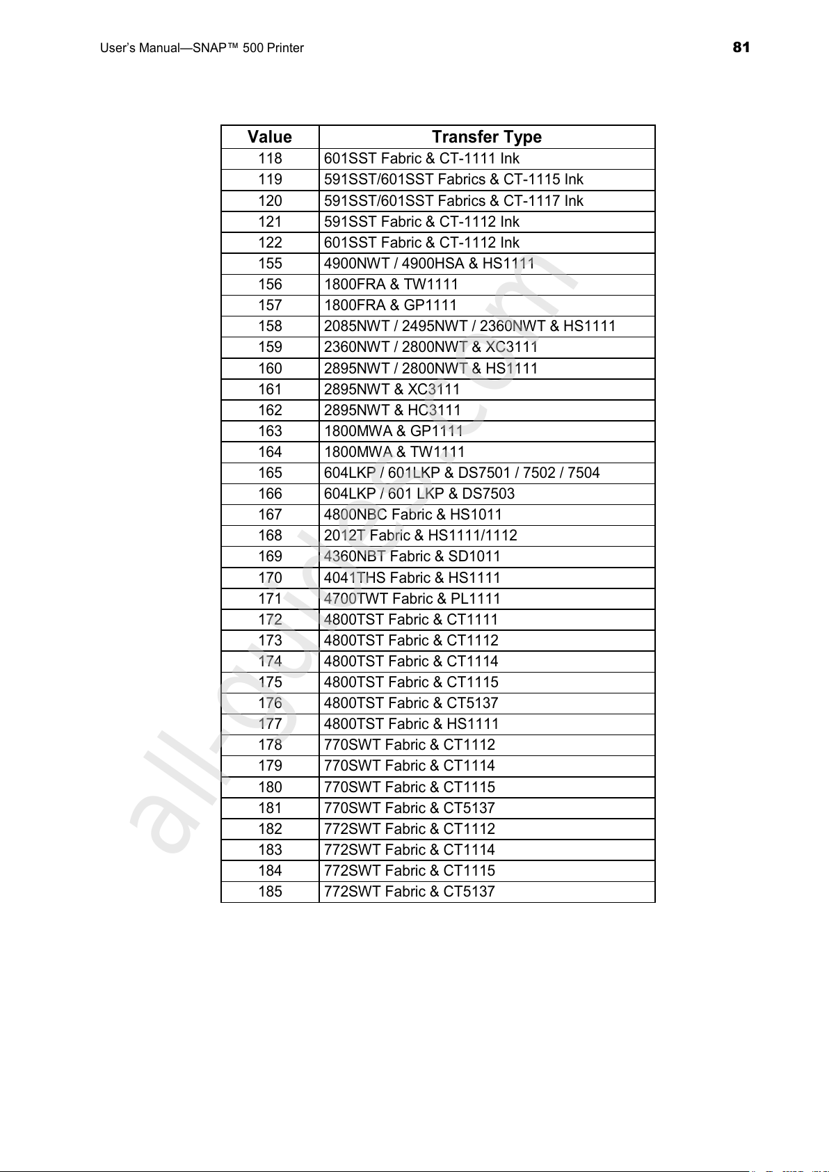
User’s Manual—SNAP™ 500 Printer
81
Value Transfer Type
118 601SST Fabric & CT-1111 Ink
119 591SST/601SST Fabrics & CT-1115 Ink
120 591SST/601SST Fabrics & CT-1117 Ink
121 591SST Fabric & CT-1112 Ink
122 601SST Fabric & CT-1112 Ink
155 4900NWT / 4900HSA & HS1111
156 1800FRA & TW1111
157 1800FRA & GP1111
158 2085NWT / 2495NWT / 2360NWT & HS1111
159 2360NWT / 2800NWT & XC3111
160 2895NWT / 2800NWT & HS1111
161 2895NWT & XC3111
162 2895NWT & HC3111
163 1800MWA & GP1111
164 1800MWA & TW1111
165 604LKP / 601LKP & DS7501 / 7502 / 7504
166 604LKP / 601 LKP & DS7503
167 4800NBC Fabric & HS1011
168 2012T Fabric & HS1111/1112
169 4360NBT Fabric & SD1011
170 4041THS Fabric & HS1111
171 4700TWT Fabric & PL1111
172 4800TST Fabric & CT1111
173 4800TST Fabric & CT1112
174 4800TST Fabric & CT1114
175 4800TST Fabric & CT1115
176 4800TST Fabric & CT5137
177 4800TST Fabric & HS1111
178 770SWT Fabric & CT1112
179 770SWT Fabric & CT1114
180 770SWT Fabric & CT1115
181 770SWT Fabric & CT5137
182 772SWT Fabric & CT1112
183 772SWT Fabric & CT1114
184 772SWT Fabric & CT1115
185 772SWT Fabric & CT5137
All manuals and user guides at all-guides.com
all-guides.com
Page 82
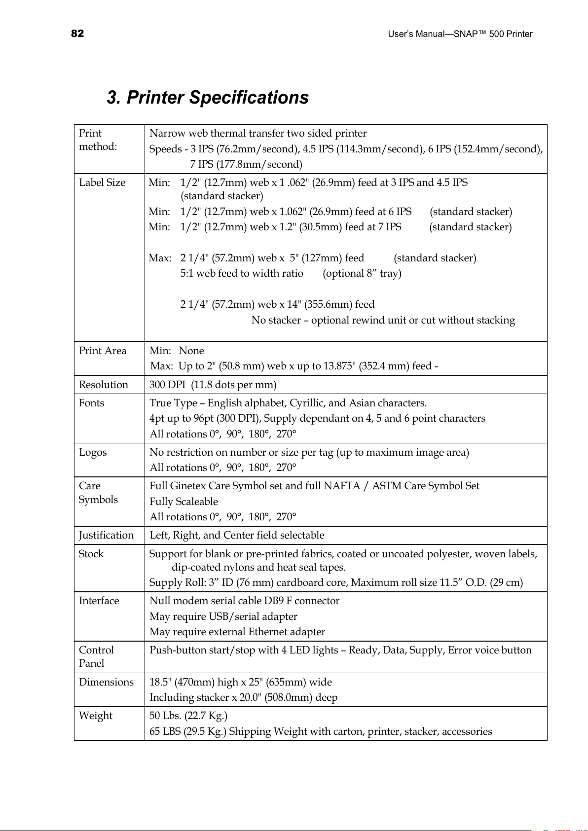
82
User’s Manual—SNAP™ 500 Printer
3. Printer Specifications
Print
method:
Narrow web thermal transfer two sided printer
Speeds - 3 IPS (76.2mm/second), 4.5 IPS (114.3mm/second), 6 IPS (152.4mm/second),
7 IPS (177.8mm/second)
Label Size Min: 1/2" (12.7mm) web x 1 .062" (26.9mm) feed at 3 IPS and 4.5 IPS
(standard stacker)
Min: 1/2" (12.7mm) web x 1.062" (26.9mm) feed at 6 IPS (standard stacker)
Min: 1/2" (12.7mm) web x 1.2" (30.5mm) feed at 7 IPS (standard stacker)
Max: 2 1/4" (57.2mm) web x 5" (127mm) feed (standard stacker)
5:1 web feed to width ratio (optional 8” tray)
2 1/4" (57.2mm) web x 14" (355.6mm) feed
No stacker – optional rewind unit or cut without stacking
Print Area Min: None
Max: Up to 2" (50.8 mm) web x up to 13.875" (352.4 mm) feed -
Resolution 300 DPI (11.8 dots per mm)
Fonts True Type – English alphabet, Cyrillic, and Asian characters.
4pt up to 96pt (300 DPI), Supply dependant on 4, 5 and 6 point characters
All rotations 0°, 90°, 180°, 270°
Logos No restriction on number or size per tag (up to maximum image area)
All rotations 0°, 90°, 180°, 270°
Care
Symbols
Full Ginetex Care Symbol set and full NAFTA / ASTM Care Symbol Set
Fully Scaleable
All rotations 0°, 90°, 180°, 270°
Justification Left, Right, and Center field selectable
Stock Support for blank or pre-printed fabrics, coated or uncoated polyester, woven labels,
dip-coated nylons and heat seal tapes.
Supply Roll: 3” ID (76 mm) cardboard core, Maximum roll size 11.5” O.D. (29 cm)
Interface Null modem serial cable DB9 F connector
May require USB/serial adapter
May require external Ethernet adapter
Control
Panel
Push-button start/stop with 4 LED lights – Ready, Data, Supply, Error voice button
Dimensions 18.5" (470mm) high x 25" (635mm) wide
Including stacker x 20.0" (508.0mm) deep
Weight 50 Lbs. (22.7 Kg.)
65 LBS (29.5 Kg.) Shipping Weight with carton, printer, stacker, accessories
All manuals and user guides at all-guides.com
Page 83
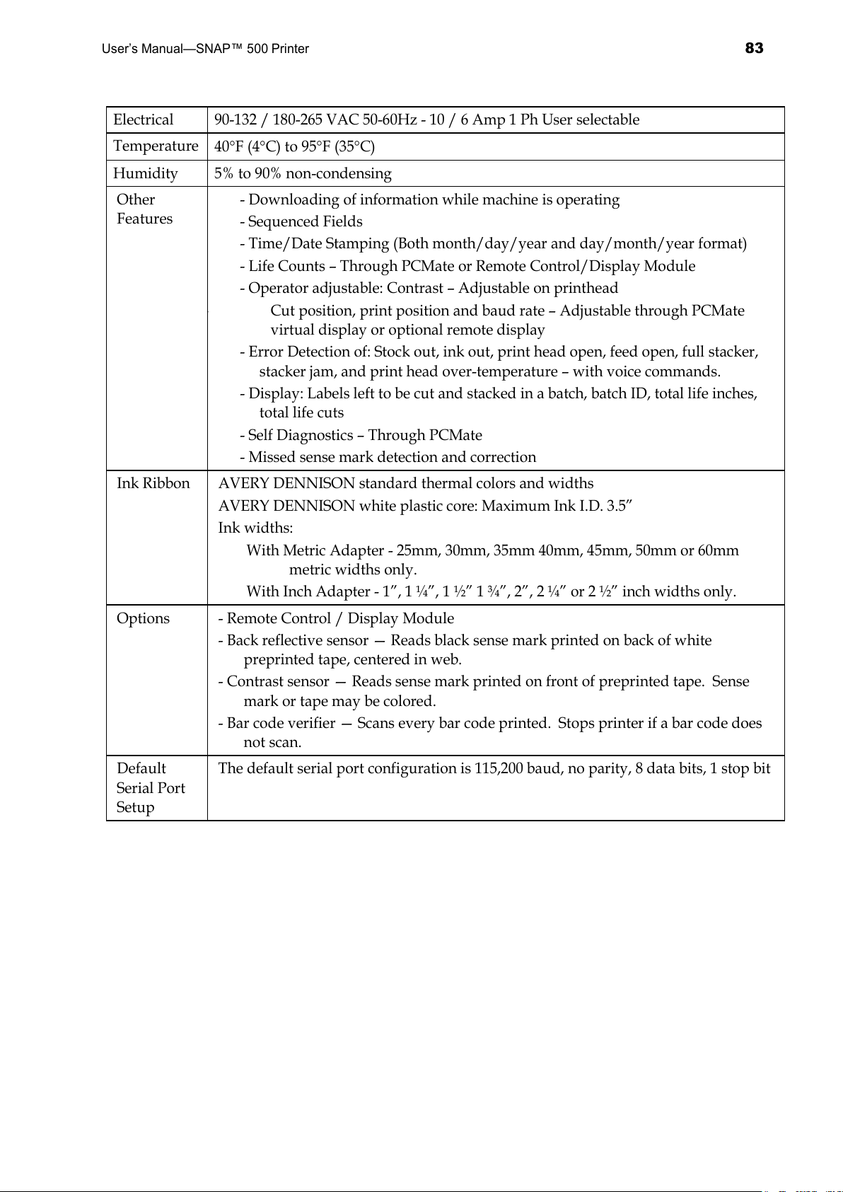
User’s Manual—SNAP™ 500 Printer
83
Electrical 90-132 / 180-265 VAC 50-60Hz - 10 / 6 Amp 1 Ph User selectable
Temperature
40°F (4°C) to 95°F (35°C)
Humidity 5% to 90% non-condensing
Other
Features
- Downloading of information while machine is operating
- Sequenced Fields
- Time/Date Stamping (Both month/day/year and day/month/year format)
- Life Counts – Through PCMate or Remote Control/Display Module
- Operator adjustable: Contrast – Adjustable on printhead
Cut position, print position and baud rate – Adjustable through PCMate
virtual display or optional remote display
- Error Detection of: Stock out, ink out, print head open, feed open, full stacker,
stacker jam, and print head over-temperature – with voice commands.
- Display: Labels left to be cut and stacked in a batch, batch ID, total life inches,
total life cuts
- Self Diagnostics – Through PCMate
- Missed sense mark detection and correction
Ink Ribbon AVERY DENNISON standard thermal colors and widths
AVERY DENNISON white plastic core: Maximum Ink I.D. 3.5”
Ink widths:
With Metric Adapter - 25mm, 30mm, 35mm 40mm, 45mm, 50mm or 60mm
metric widths only.
With Inch Adapter - 1”, 1 ¼”, 1 ½” 1 ¾”, 2”, 2 ¼” or 2 ½” inch widths only.
Options - Remote Control / Display Module
- Back reflective sensor — Reads black sense mark printed on back of white
preprinted tape, centered in web.
- Contrast sensor — Reads sense mark printed on front of preprinted tape. Sense
mark or tape may be colored.
- Bar code verifier — Scans every bar code printed. Stops printer if a bar code does
not scan.
Default
Serial Port
Setup
The default serial port configuration is 115,200 baud, no parity, 8 data bits, 1 stop bit
All manuals and user guides at all-guides.com
Page 84
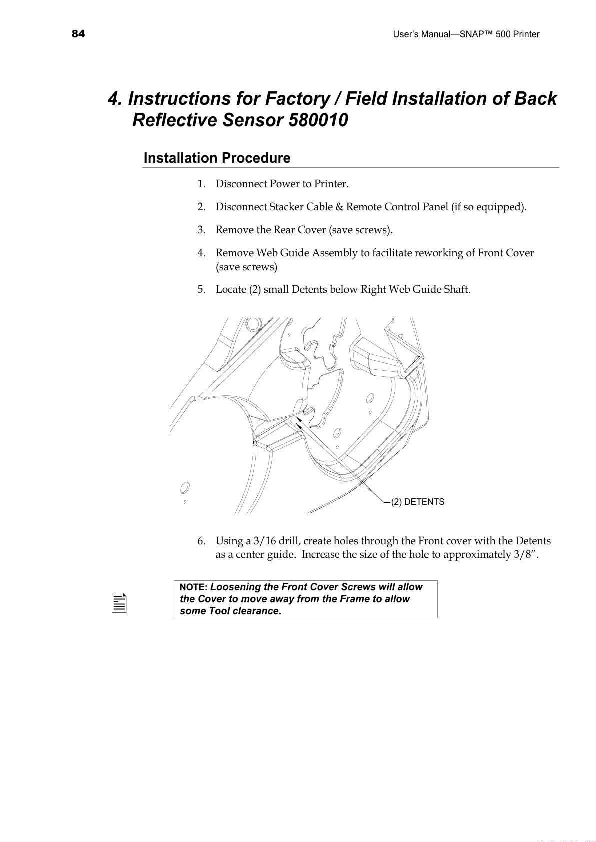
84
User’s Manual—SNAP™ 500 Printer
4. Instructions for Factory / Field Installation of Back
Reflective Sensor 580010
Installation Procedure
1. Disconnect Power to Printer.
2. Disconnect Stacker Cable & Remote Control Panel (if so equipped).
3. Remove the Rear Cover (save screws).
4. Remove Web Guide Assembly to facilitate reworking of Front Cover
(save screws)
5. Locate (2) small Detents below Right Web Guide Shaft.
(2) DETENTS
6. Using a 3/16 drill, create holes through the Front cover with the Detents
as a center guide. Increase the size of the hole to approximately 3/8”.
NOTE:
Loosening the Front Cover Screws will allow
the Cover to move away from the Frame to allow
some Tool clearance.
All manuals and user guides at all-guides.com
Page 85
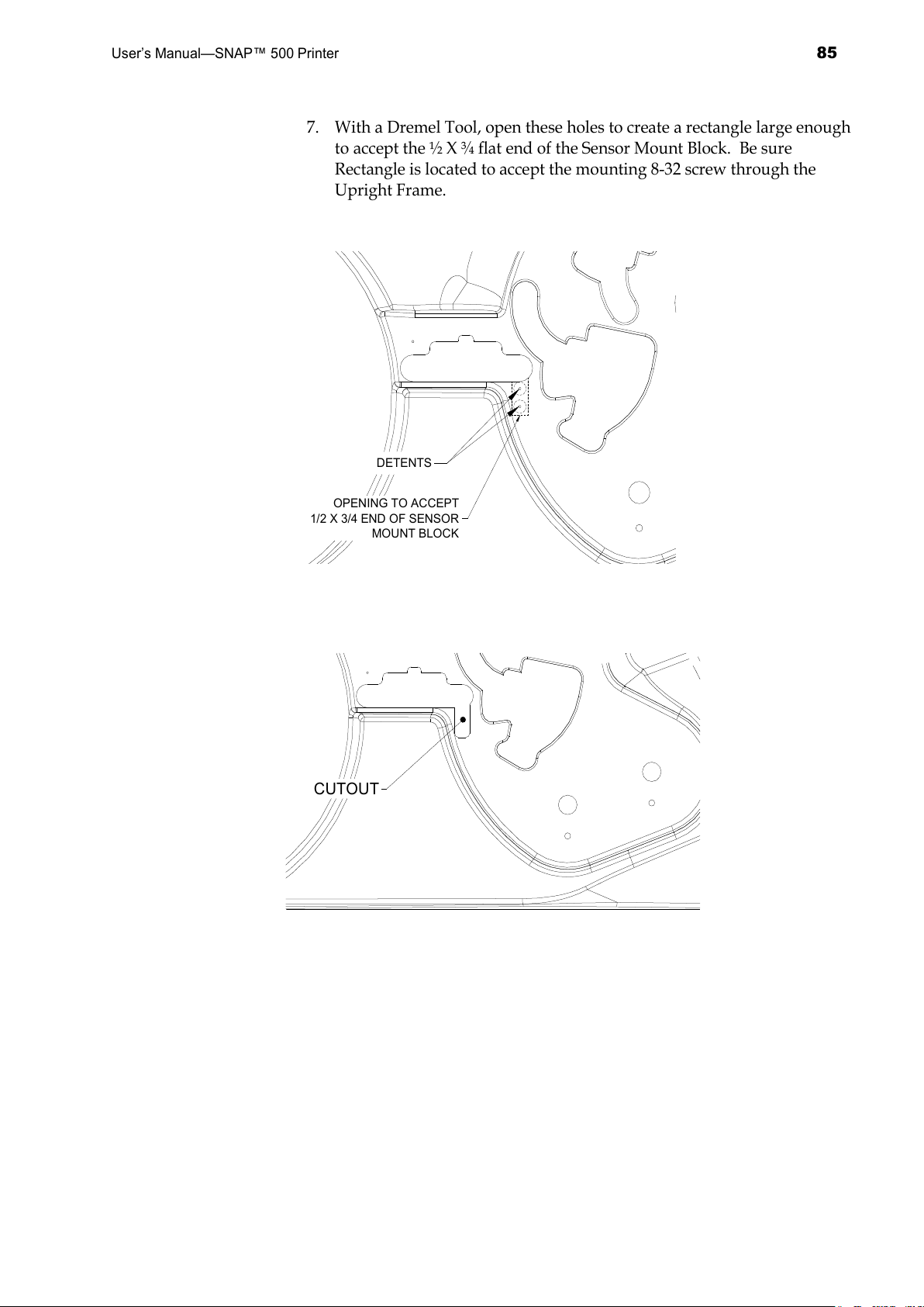
User’s Manual—SNAP™ 500 Printer
85
7. With a Dremel Tool, open these holes to create a rectangle large enough
to accept the ½ X ¾ flat end of the Sensor Mount Block. Be sure
Rectangle is located to accept the mounting 8-32 screw through the
Upright Frame.
OPENING TO ACCEPT
1/2 X 3/4 END OF SENSOR
MOUNT BLOCK
DETENTS
CUTOUT
All manuals and user guides at all-guides.com
Page 86
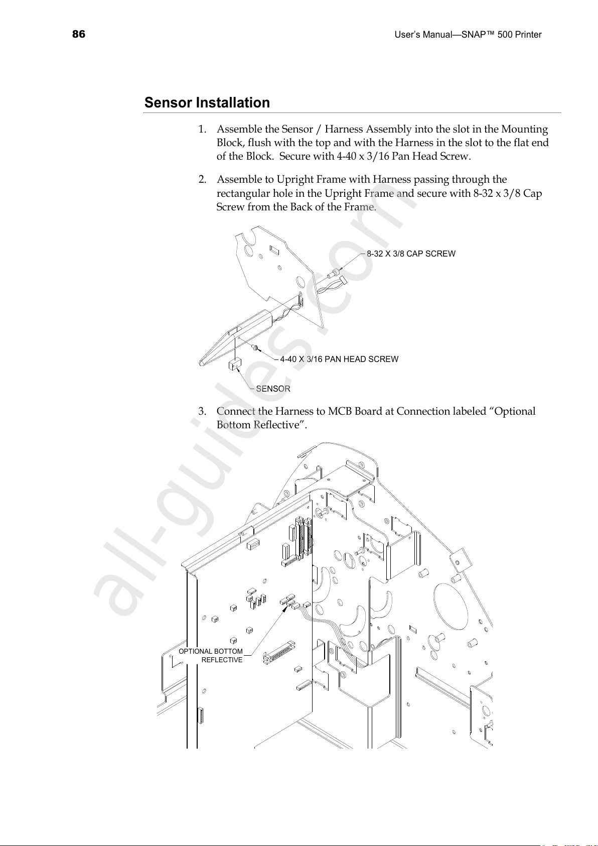
86
User’s Manual—SNAP™ 500 Printer
Sensor Installation
1. Assemble the Sensor / Harness Assembly into the slot in the Mounting
Block, flush with the top and with the Harness in the slot to the flat end
of the Block. Secure with 4-40 x 3/16 Pan Head Screw.
2. Assemble to Upright Frame with Harness passing through the
rectangular hole in the Upright Frame and secure with 8-32 x 3/8 Cap
Screw from the Back of the Frame.
SENSOR
4-40 X 3/16 PAN HEAD SCREW
8-32 X 3/8 CAP SCREW
3. Connect the Harness to MCB Board at Connection labeled “Optional
Bottom Reflective”.
OPTIONAL BOTTOM
REFLECTIVE
All manuals and user guides at all-guides.com
all-guides.com
Page 87
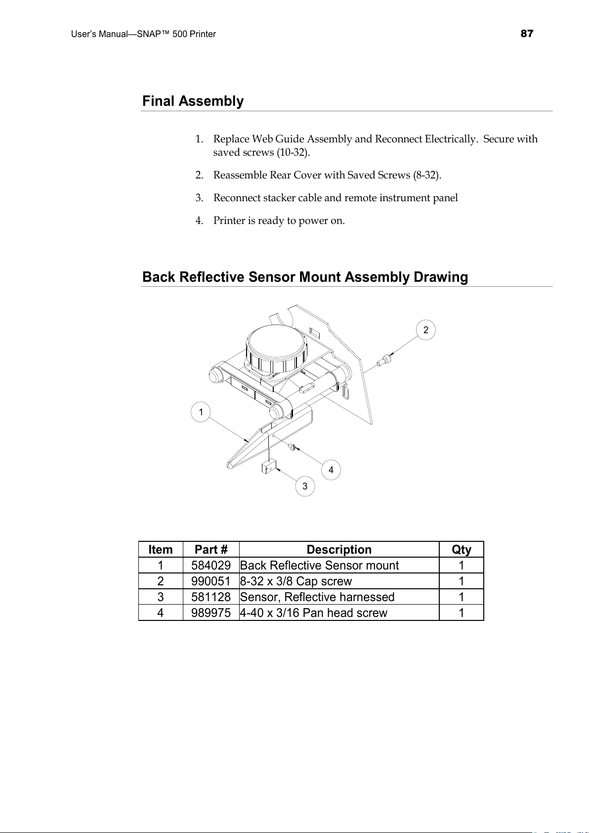
User’s Manual—SNAP™ 500 Printer
87
Final Assembly
1. Replace Web Guide Assembly and Reconnect Electrically. Secure with
saved screws (10-32).
2. Reassemble Rear Cover with Saved Screws (8-32).
3. Reconnect stacker cable and remote instrument panel
4. Printer is ready to power on.
Back Reflective Sensor Mount Assembly Drawing
1
3
4
2
Item Part # Description Qty
1 584029 Back Reflective Sensor mount 1
2 990051 8-32 x 3/8 Cap screw 1
3 581128 Sensor, Reflective harnessed 1
4 989975 4-40 x 3/16 Pan head screw 1
All manuals and user guides at all-guides.com
Page 88
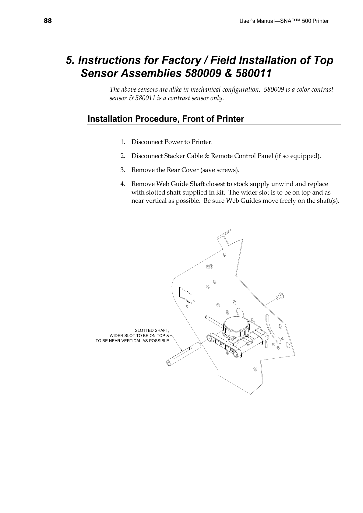
88
User’s Manual—SNAP™ 500 Printer
5. Instructions for Factory / Field Installation of Top
Sensor Assemblies 580009 & 580011
The above sensors are alike in mechanical configuration. 580009 is a color contrast
sensor & 580011 is a contrast sensor only.
Installation Procedure, Front of Printer
1. Disconnect Power to Printer.
2. Disconnect Stacker Cable & Remote Control Panel (if so equipped).
3. Remove the Rear Cover (save screws).
4. Remove Web Guide Shaft closest to stock supply unwind and replace
with slotted shaft supplied in kit. The wider slot is to be on top and as
near vertical as possible. Be sure Web Guides move freely on the shaft(s).
SLOTTED SHAFT,
WIDER SLOT TO BE ON TOP &
TO BE NEAR VERTICAL AS POSSIBLE
All manuals and user guides at all-guides.com
Page 89
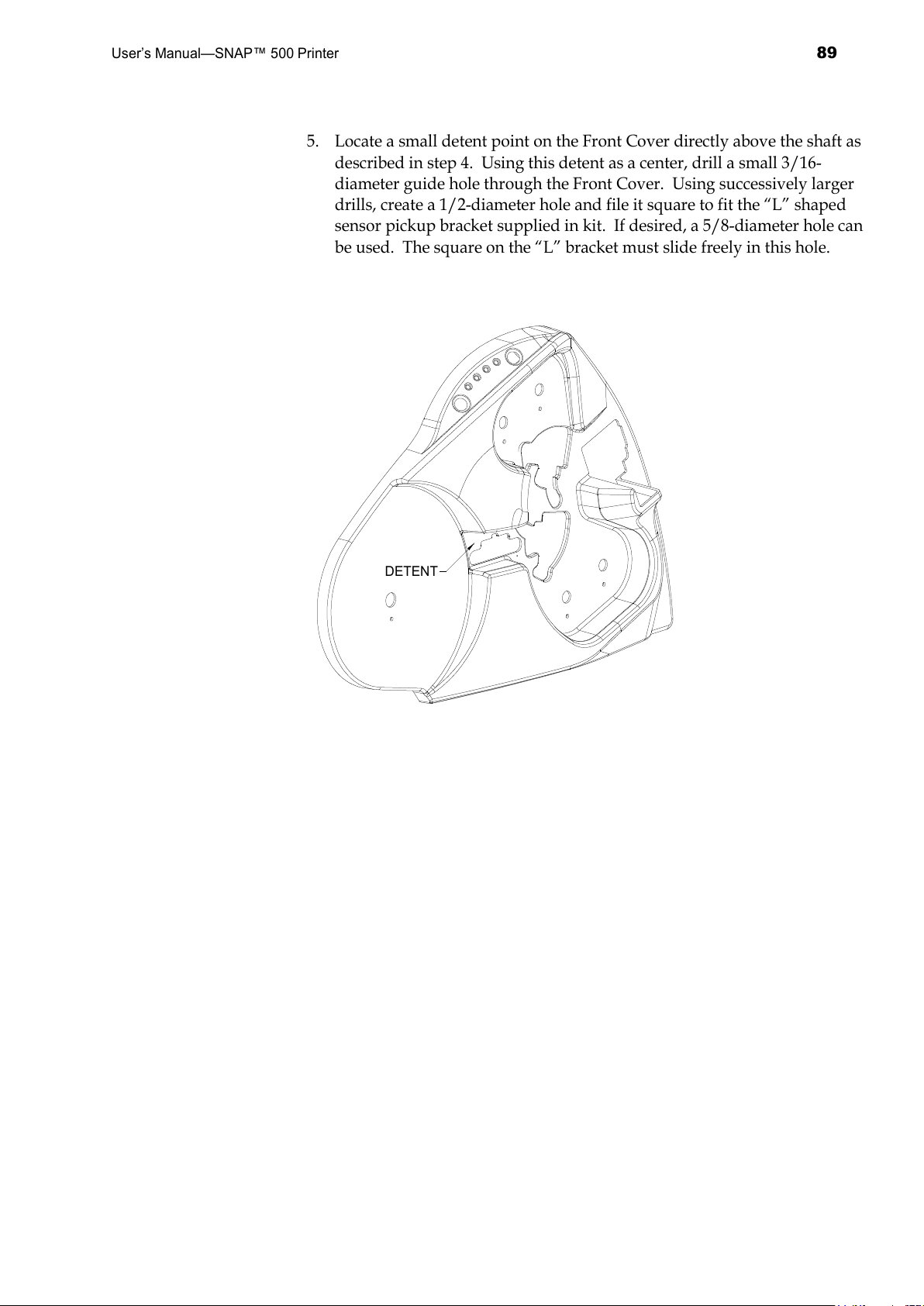
User’s Manual—SNAP™ 500 Printer
89
5. Locate a small detent point on the Front Cover directly above the shaft as
described in step 4. Using this detent as a center, drill a small 3/16-
diameter guide hole through the Front Cover. Using successively larger
drills, create a 1/2-diameter hole and file it square to fit the “L” shaped
sensor pickup bracket supplied in kit. If desired, a 5/8-diameter hole can
be used. The square on the “L” bracket must slide freely in this hole.
DETENT
All manuals and user guides at all-guides.com
Page 90
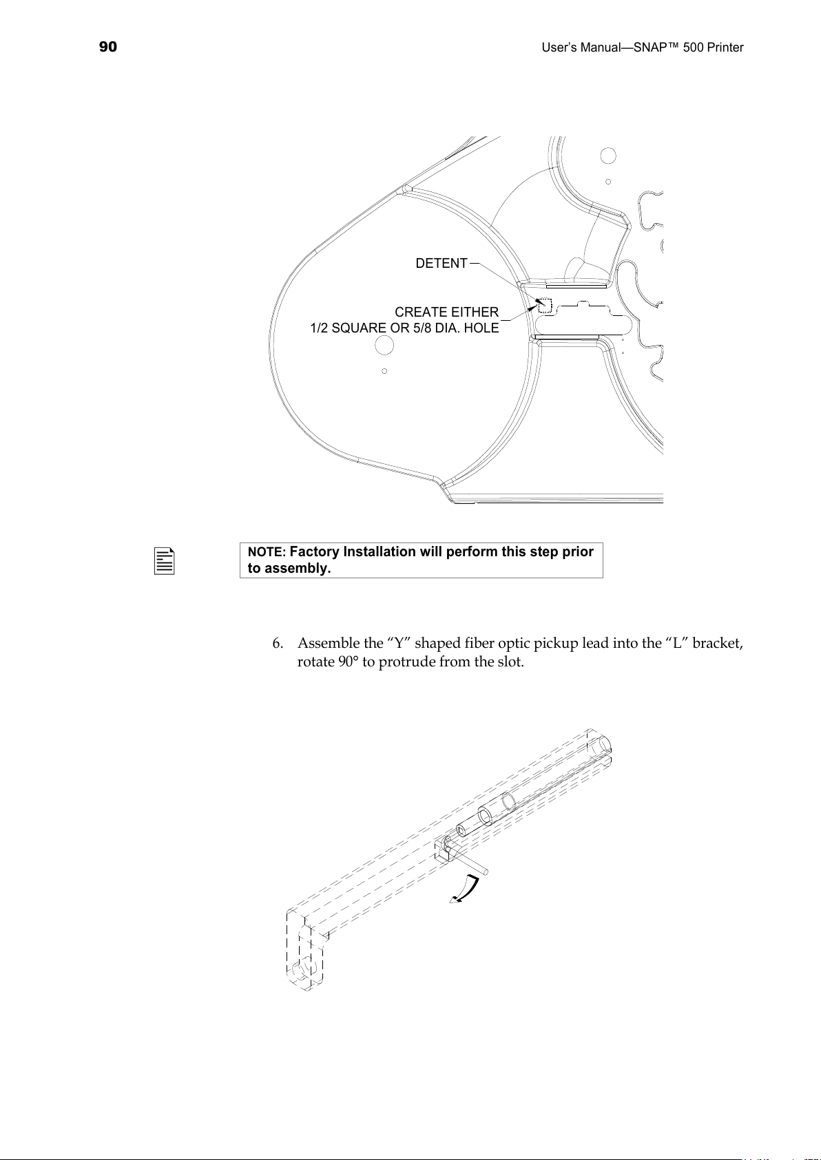
90
User’s Manual—SNAP™ 500 Printer
DETENT
CREATE EITHER
1/2 SQUARE OR 5/8 DIA. HOLE
NOTE:
Factory Installation will perform this step prior
to assembly.
6. Assemble the “Y” shaped fiber optic pickup lead into the “L” bracket,
rotate 90° to protrude from the slot.
All manuals and user guides at all-guides.com
Page 91
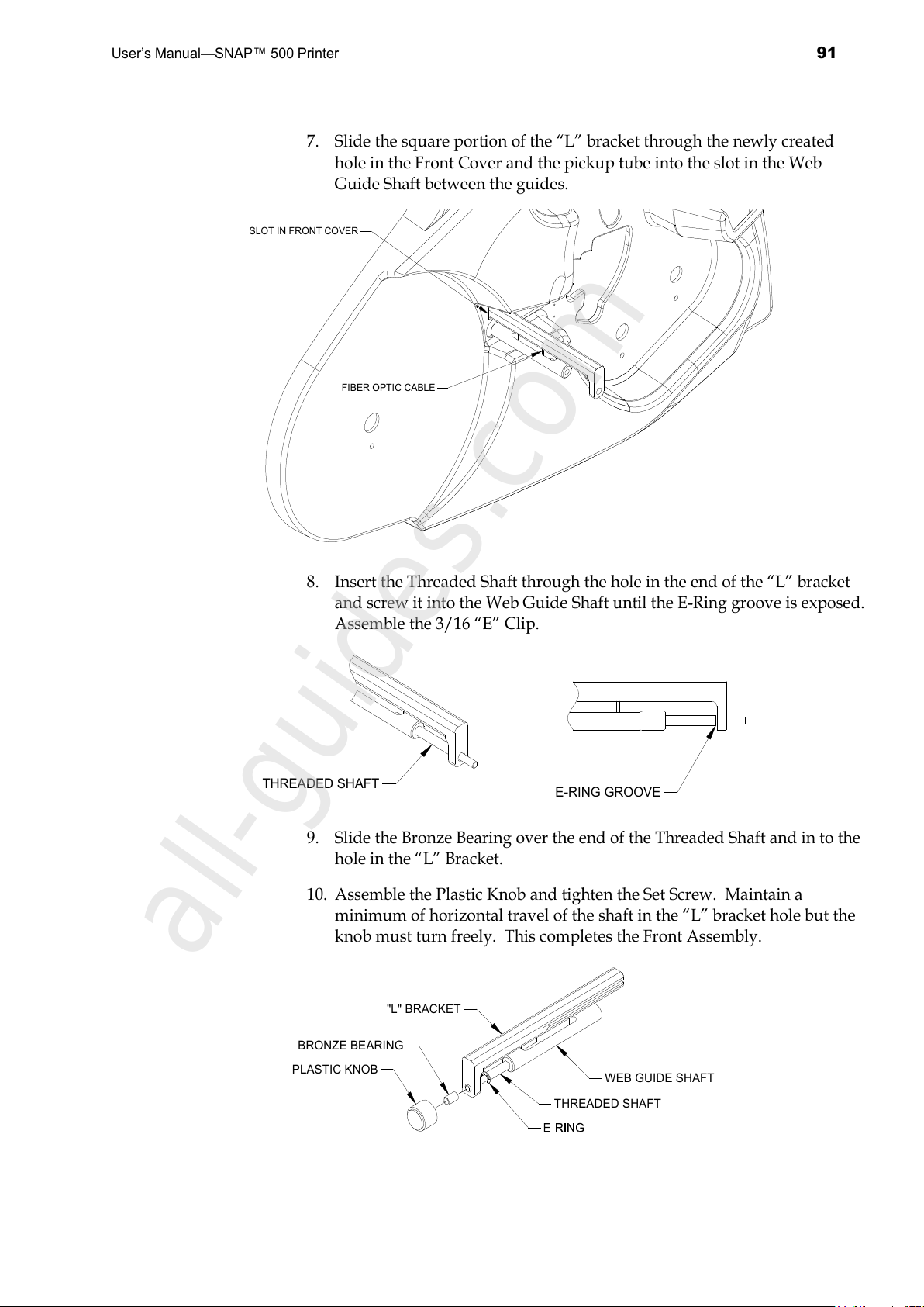
User’s Manual—SNAP™ 500 Printer
91
7. Slide the square portion of the “L” bracket through the newly created
hole in the Front Cover and the pickup tube into the slot in the Web
Guide Shaft between the guides.
FIBER OPTIC CABLE
SLOT IN FRONT COVER
8. Insert the Threaded Shaft through the hole in the end of the “L” bracket
and screw it into the Web Guide Shaft until the E-Ring groove is exposed.
Assemble the 3/16 “E” Clip.
THREADED SHAFT
E-RING GROOVE
9. Slide the Bronze Bearing over the end of the Threaded Shaft and in to the
hole in the “L” Bracket.
10. Assemble the Plastic Knob and tighten the Set Screw. Maintain a
minimum of horizontal travel of the shaft in the “L” bracket hole but the
knob must turn freely. This completes the Front Assembly.
WEB GUIDE SHAFT
PLASTIC KNOB
THREADED SHAFT
BRONZE BEARING
"L" BRACKET
All manuals and user guides at all-guides.com
all-guides.com
Page 92
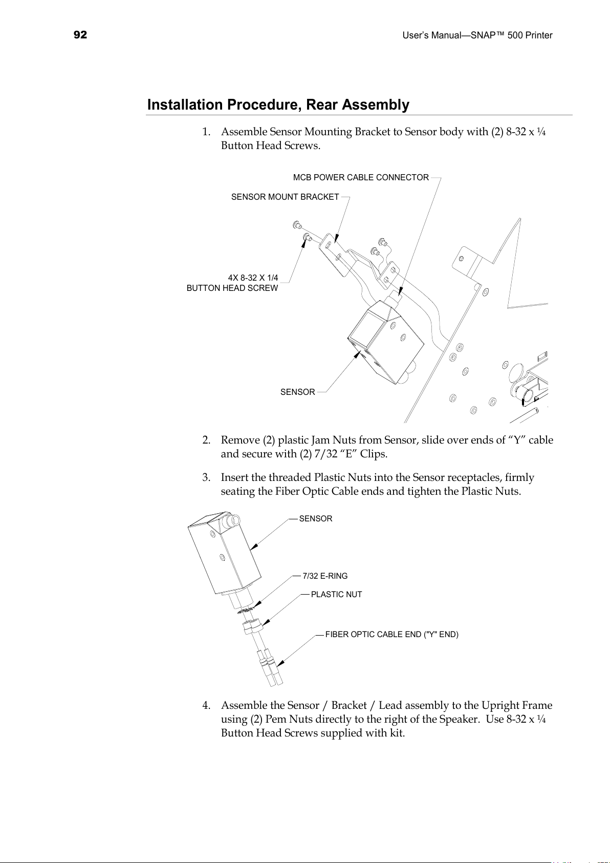
92
User’s Manual—SNAP™ 500 Printer
Installation Procedure, Rear Assembly
1. Assemble Sensor Mounting Bracket to Sensor body with (2) 8-32 x ¼
Button Head Screws.
SENSOR
4X 8-32 X 1/4
BUTTON HEAD SCREW
SENSOR MOUNT BRACKET
MCB POWER CABLE CONNECTOR
2. Remove (2) plastic Jam Nuts from Sensor, slide over ends of “Y” cable
and secure with (2) 7/32 “E” Clips.
3. Insert the threaded Plastic Nuts into the Sensor receptacles, firmly
seating the Fiber Optic Cable ends and tighten the Plastic Nuts.
7/32 E-RING
FIBER OPTIC CABLE END ("Y" END)
PLASTIC NUT
SENSOR
4. Assemble the Sensor / Bracket / Lead assembly to the Upright Frame
using (2) Pem Nuts directly to the right of the Speaker. Use 8-32 x ¼
Button Head Screws supplied with kit.
All manuals and user guides at all-guides.com
Page 93

User’s Manual—SNAP™ 500 Printer
93
5. Assemble Sensor Power Cable to Sensor and plug into MCB Connector
labeled “Option Top Color / Contrast”.
All manuals and user guides at all-guides.com
Page 94
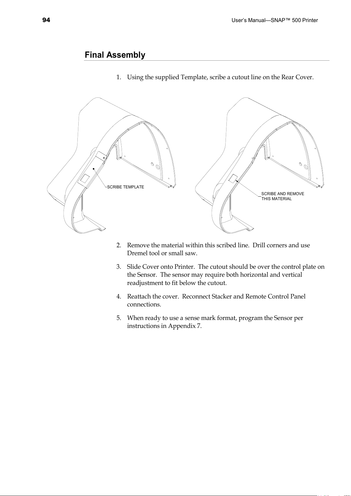
94
User’s Manual—SNAP™ 500 Printer
Final Assembly
1. Using the supplied Template, scribe a cutout line on the Rear Cover.
SCRIBE TEMPLATE
SCRIBE AND REMOVE
THIS MATERIAL
2. Remove the material within this scribed line. Drill corners and use
Dremel tool or small saw.
3. Slide Cover onto Printer. The cutout should be over the control plate on
the Sensor. The sensor may require both horizontal and vertical
readjustment to fit below the cutout.
4. Reattach the cover. Reconnect Stacker and Remote Control Panel
connections.
5. When ready to use a sense mark format, program the Sensor per
instructions in Appendix 7.
All manuals and user guides at all-guides.com
Page 95
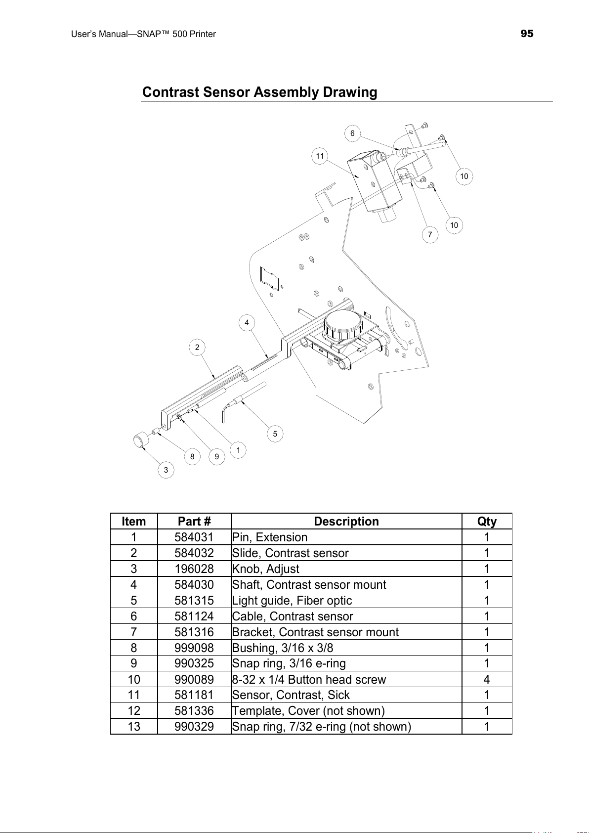
User’s Manual—SNAP™ 500 Printer
95
Contrast Sensor Assembly Drawing
4
5
2
1
3
8
9
7
10
10
11
6
Item Part # Description Qty
1 584031 Pin, Extension 1
2 584032 Slide, Contrast sensor 1
3 196028 Knob, Adjust 1
4 584030 Shaft, Contrast sensor mount 1
5 581315 Light guide, Fiber optic 1
6 581124 Cable, Contrast sensor 1
7 581316 Bracket, Contrast sensor mount 1
8 999098 Bushing, 3/16 x 3/8 1
9 990325 Snap ring, 3/16 e-ring 1
10 990089 8-32 x 1/4 Button head screw 4
11 581181 Sensor, Contrast, Sick 1
12 581336 Template, Cover (not shown) 1
13 990329 Snap ring, 7/32 e-ring (not shown) 1
All manuals and user guides at all-guides.com
Page 96
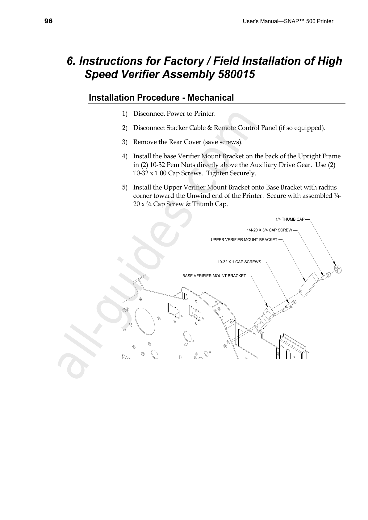
96
User’s Manual—SNAP™ 500 Printer
6. Instructions for Factory / Field Installation of High
Speed Verifier Assembly 580015
Installation Procedure - Mechanical
1) Disconnect Power to Printer.
2) Disconnect Stacker Cable & Remote Control Panel (if so equipped).
3) Remove the Rear Cover (save screws).
4) Install the base Verifier Mount Bracket on the back of the Upright Frame
in (2) 10-32 Pem Nuts directly above the Auxiliary Drive Gear. Use (2)
10-32 x 1.00 Cap Screws. Tighten Securely.
5) Install the Upper Verifier Mount Bracket onto Base Bracket with radius
corner toward the Unwind end of the Printer. Secure with assembled ¼-
20 x ¾ Cap Screw & Thumb Cap.
10-32 X 1 CAP SCREWS
UPPER VERIFIER MOUNT BRACKET
1/4-20 X 3/4 CAP SCREW
BASE VERIFIER MOUNT BRACKET
1/4 THUMB CAP
All manuals and user guides at all-guides.com
all-guides.com
Page 97
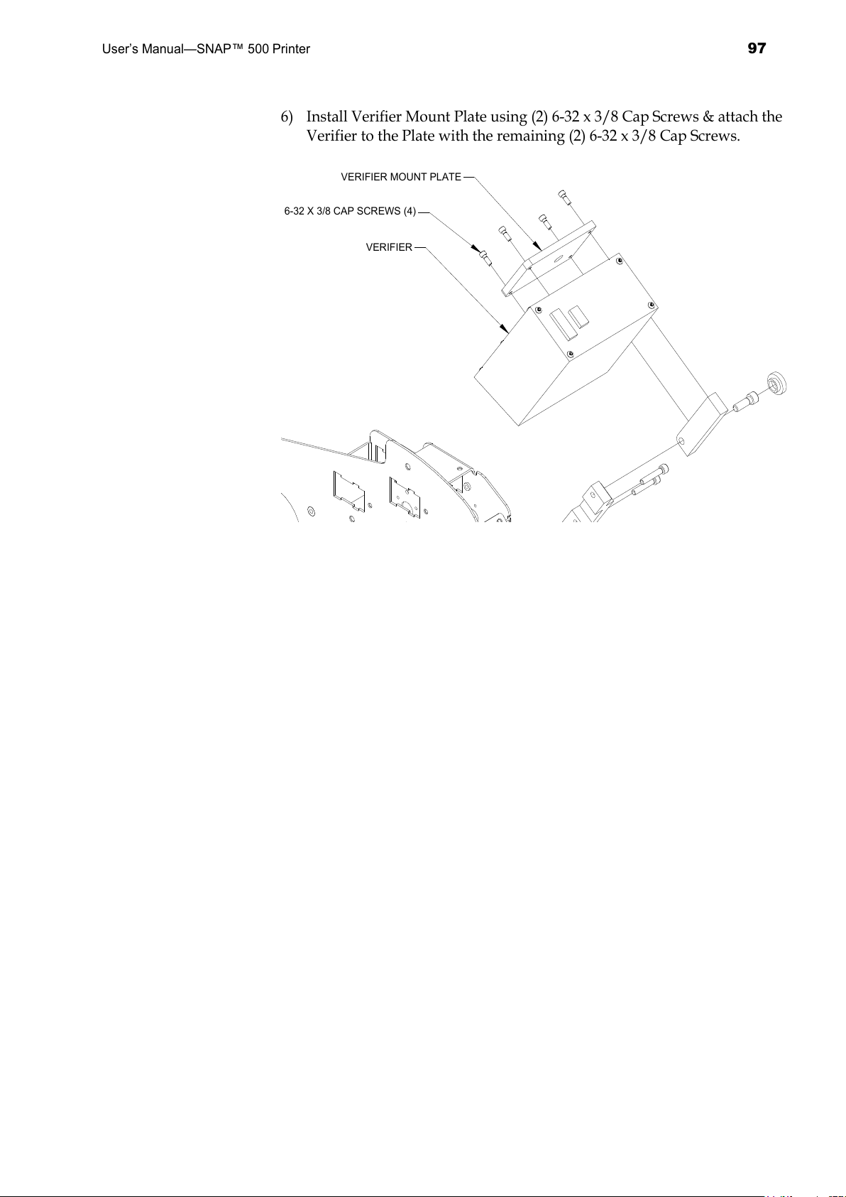
User’s Manual—SNAP™ 500 Printer
97
6) Install Verifier Mount Plate using (2) 6-32 x 3/8 Cap Screws & attach the
Verifier to the Plate with the remaining (2) 6-32 x 3/8 Cap Screws.
6-32 X 3/8 CAP SCREWS (4)
VERIFIER MOUNT PLATE
VERIFIER
All manuals and user guides at all-guides.com
Page 98
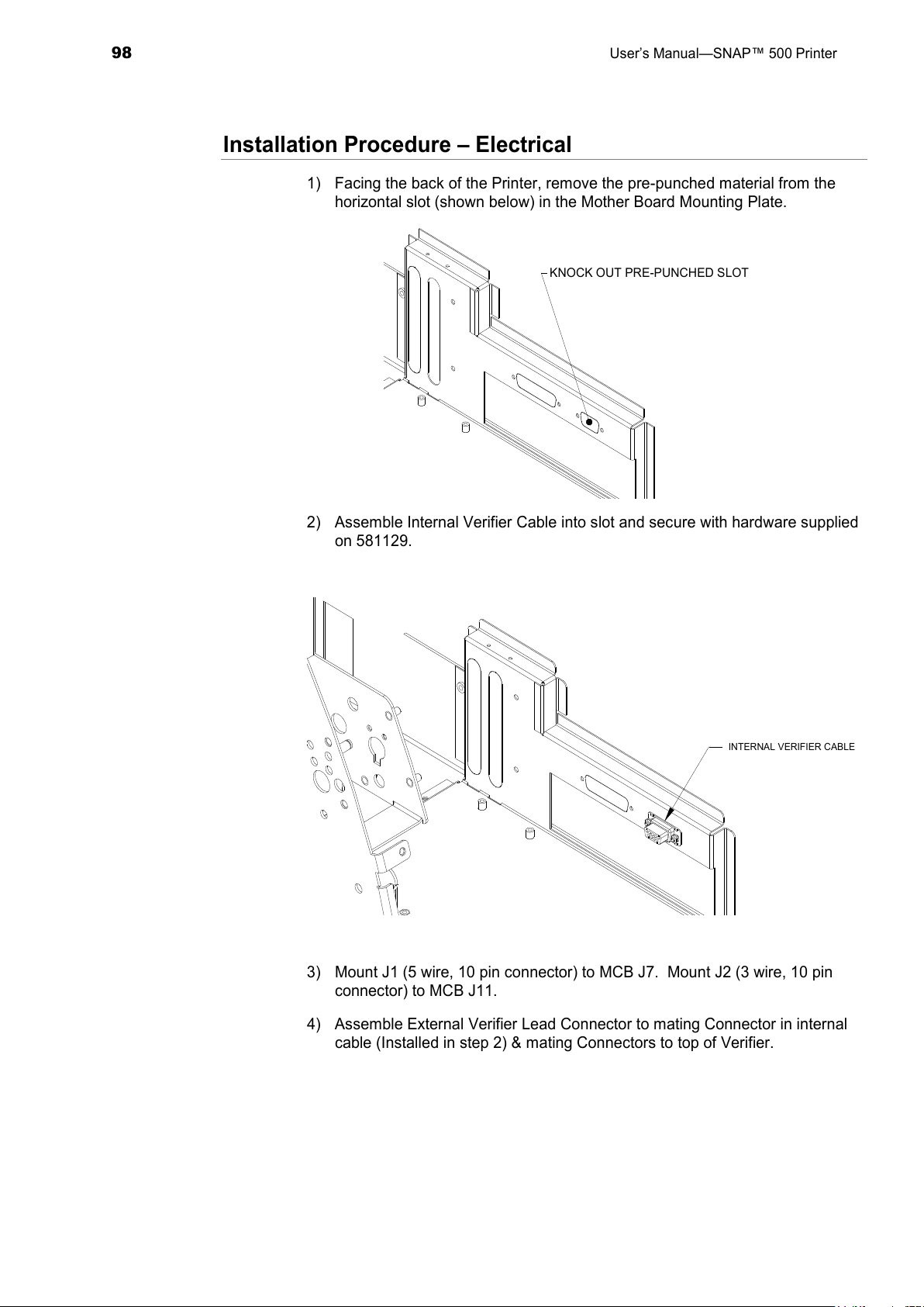
98
User’s Manual—SNAP™ 500 Printer
Installation Procedure – Electrical
1) Facing the back of the Printer, remove the pre-punched material from the
horizontal slot (shown below) in the Mother Board Mounting Plate.
KNOCK OUT PRE-PUNCHED SLOT
2) Assemble Internal Verifier Cable into slot and secure with hardware supplied
on 581129.
INTERNAL VERIFIER CABLE
3) Mount J1 (5 wire, 10 pin connector) to MCB J7. Mount J2 (3 wire, 10 pin
connector) to MCB J11.
4) Assemble External Verifier Lead Connector to mating Connector in internal
cable (Installed in step 2) & mating Connectors to top of Verifier.
All manuals and user guides at all-guides.com
Page 99
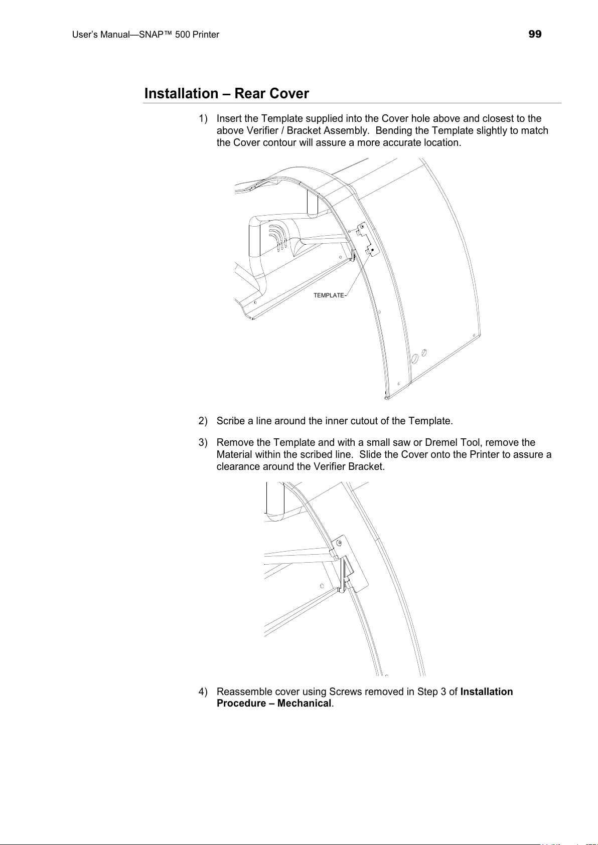
User’s Manual—SNAP™ 500 Printer
99
Installation – Rear Cover
1) Insert the Template supplied into the Cover hole above and closest to the
above Verifier / Bracket Assembly. Bending the Template slightly to match
the Cover contour will assure a more accurate location.
TEMPLATE
2) Scribe a line around the inner cutout of the Template.
3) Remove the Template and with a small saw or Dremel Tool, remove the
Material within the scribed line. Slide the Cover onto the Printer to assure a
clearance around the Verifier Bracket.
4) Reassemble cover using Screws removed in Step 3 of Installation
Procedure – Mechanical.
All manuals and user guides at all-guides.com
Page 100
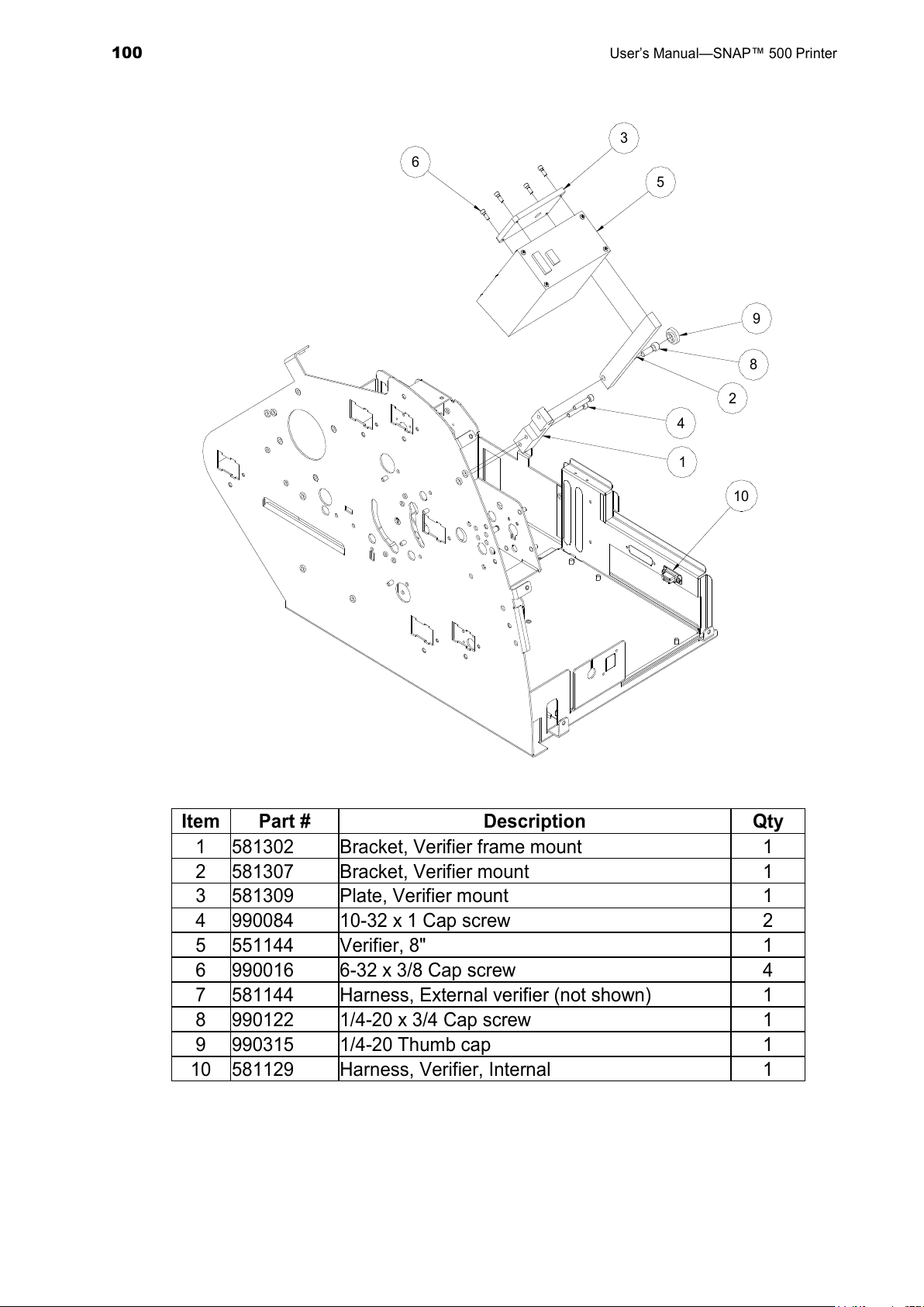
100
User’s Manual—SNAP™ 500 Printer
1
6
2
4
10
8
9
5
3
Item
Part # Description Qty
1 581302 Bracket, Verifier frame mount 1
2 581307 Bracket, Verifier mount 1
3 581309 Plate, Verifier mount 1
4 990084 10-32 x 1 Cap screw 2
5 551144 Verifier, 8" 1
6 990016 6-32 x 3/8 Cap screw 4
7 581144 Harness, External verifier (not shown) 1
8 990122 1/4-20 x 3/4 Cap screw 1
9 990315 1/4-20 Thumb cap 1
10 581129 Harness, Verifier, Internal 1
All manuals and user guides at all-guides.com
 Loading...