

Page 1

User / Service Manual Power Stacker
10/06 Rev. 1.09 1
Manual
Power Stacker
Page 2

User / Service Manual Power Stacker
10/06 Rev. 1.09 2
Contents
Contents...............................................................................................................................2
General.................................................................................................................................3
Copyright..........................................................................................................................................3
What is a "power stacker" ? .............................................................................................................3
Initiation................................................................................................................................4
Unpacking ........................................................................................................................................4
Assembling the Power Stacker ........................................................................................................5
Mounting the option to the TDI.........................................................................................................6
Assemble light cover........................................................................................................................7
Set up mode.........................................................................................................................8
Modes of operation - operation.............................................................................................9
Activating the sensor........................................................................................................................9
Adjusting the label width.................................................................................................................10
Adjusting the label length...............................................................................................................10
Magazine full..................................................................................................................................11
Information printout / parameter .........................................................................................12
Parameter Menu TDI......................................................................................................................12
Status printout ....................................................................................................................13
Status reports.....................................................................................................................14
ST04 Power stacker full .................................................................................................................14
Overview - Status reports...............................................................................................................15
Maintenance, cleaning and service....................................................................................19
Maintenance and cleaning.............................................................................................................19
Service............................................................................................................................................19
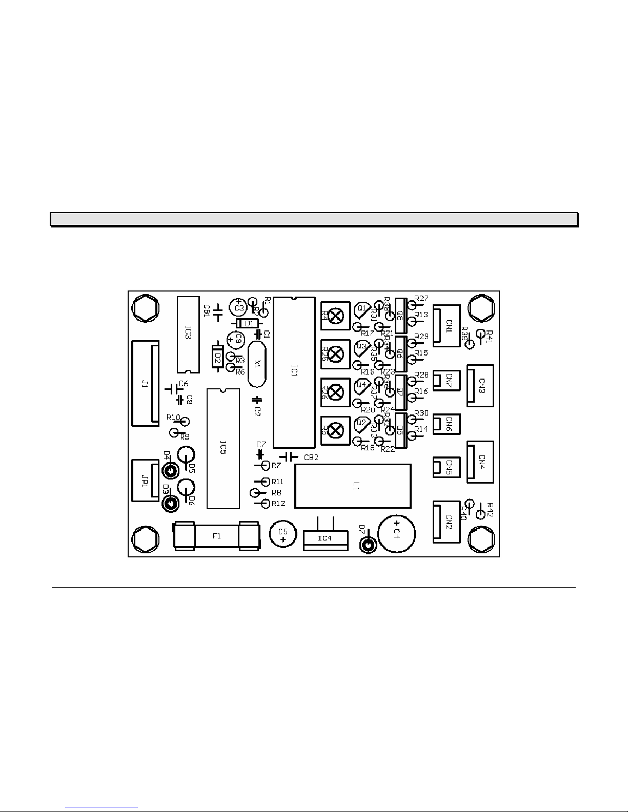
CPU board...............................................................................................................................19
Micro switch ............................................................................................................................ 20
Reflex Sensor.......................................................................................................................... 20
Stepper motor ......................................................................................................................... 21
Diagrams............................................................................................................................22
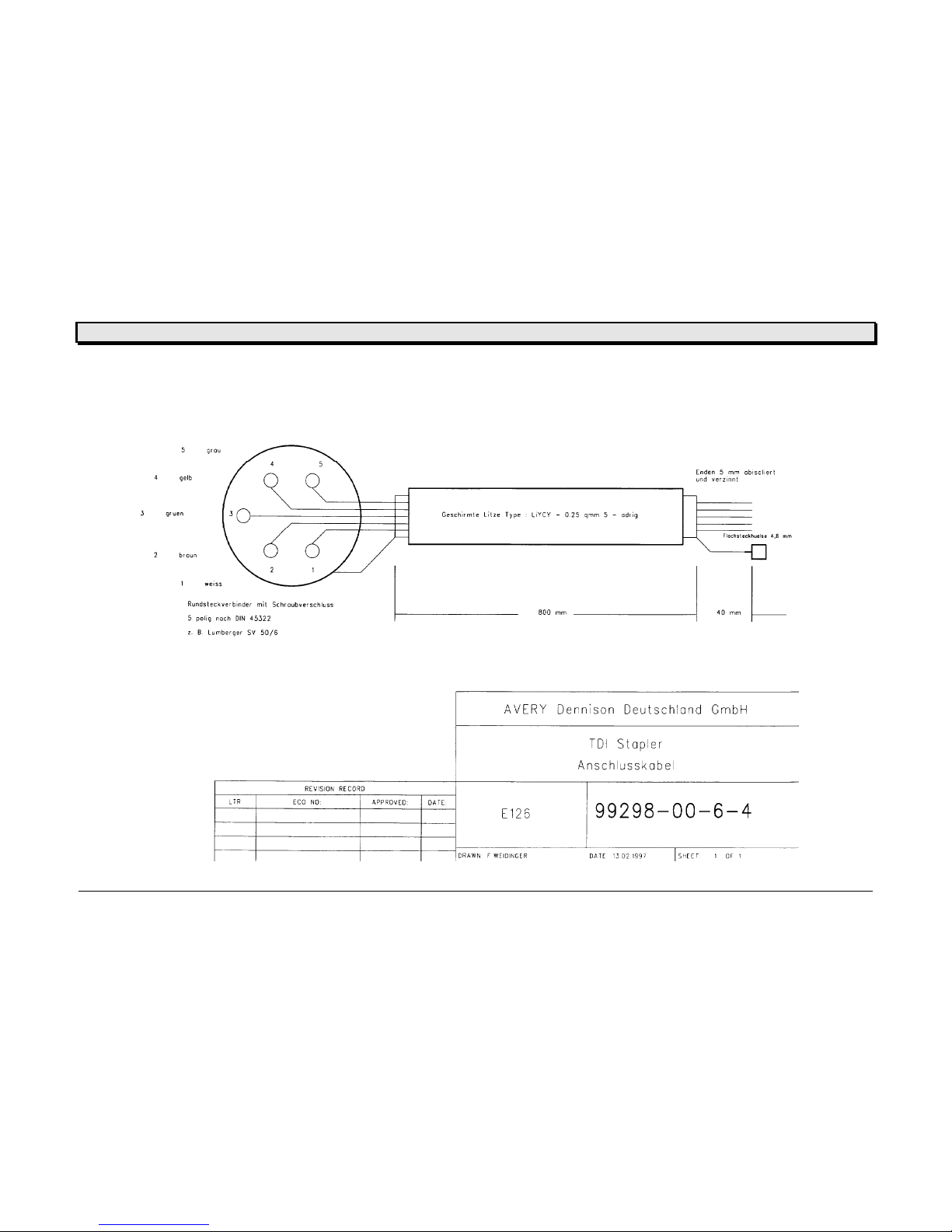
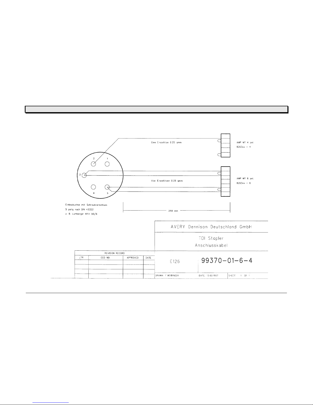
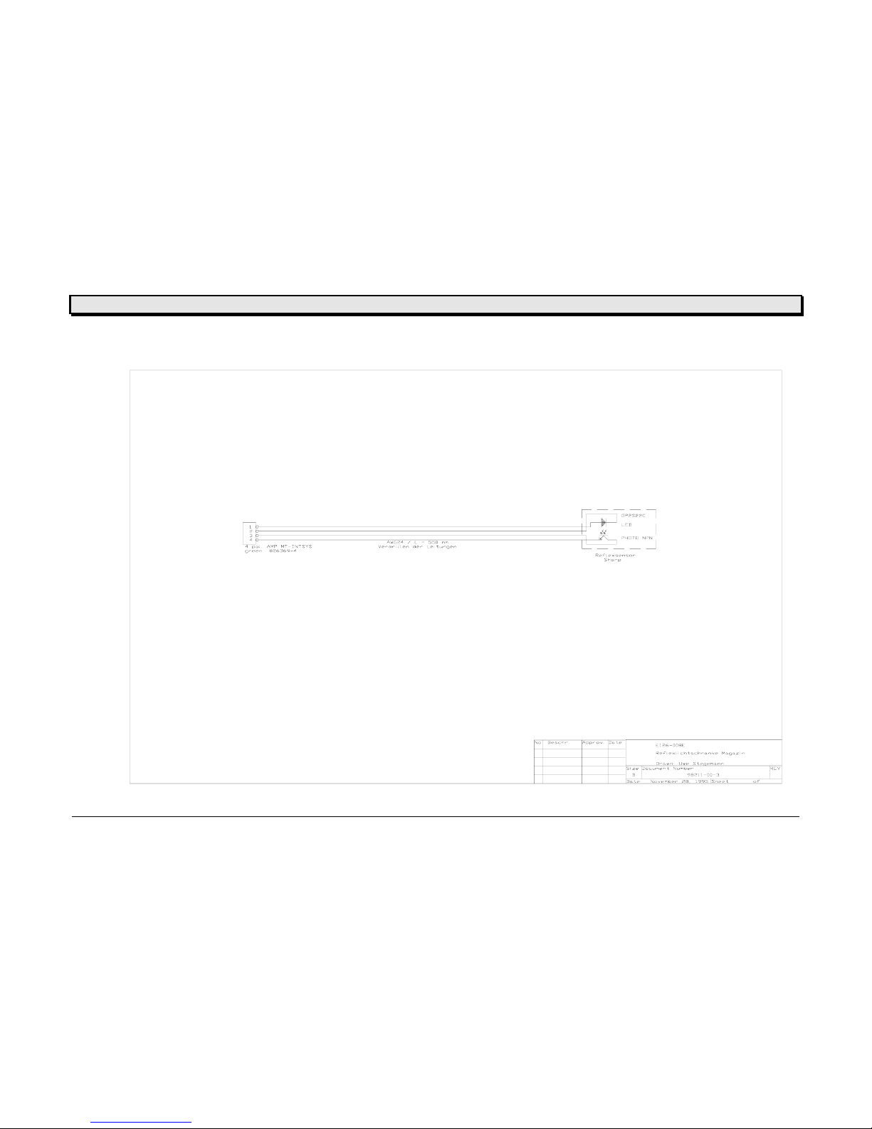
Cable drawings...............................................................................................................................23
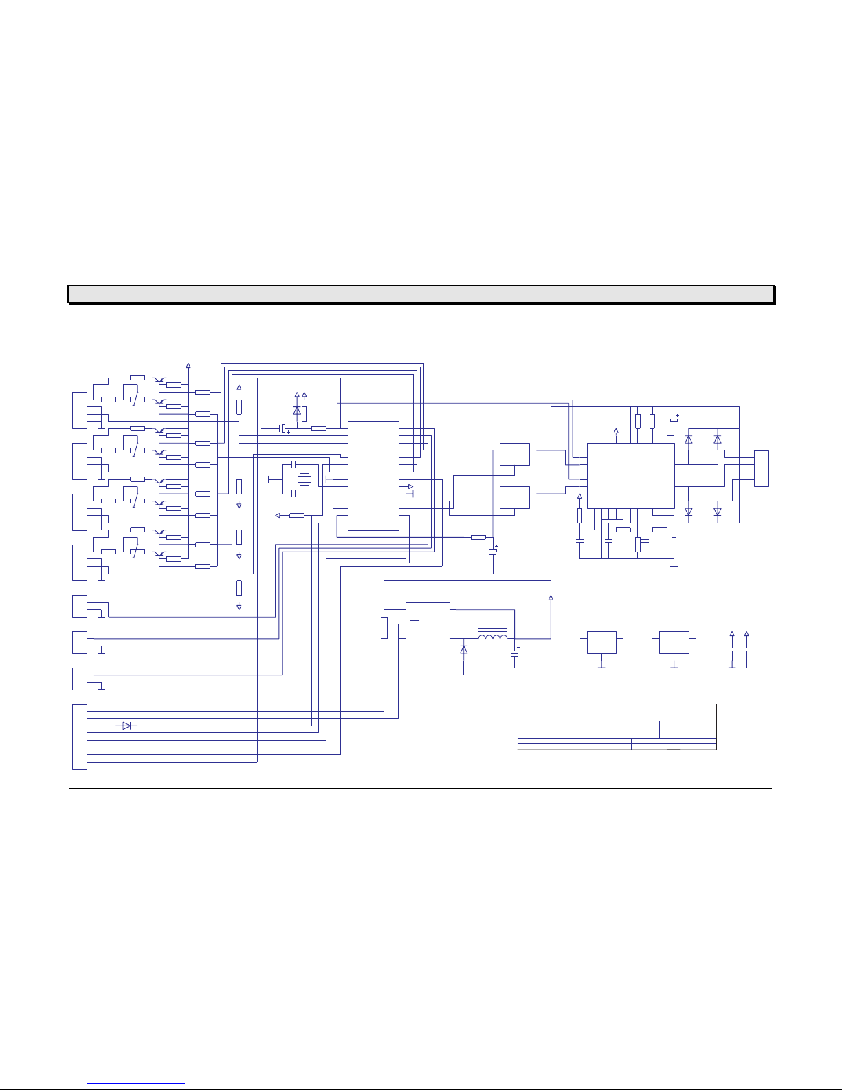
Circuit diagram CPU board............................................................................................................27
Component diagram CPU board....................................................................................................28
Spare parts list....................................................................................................................29
Index...................................................................................................................................39
Page 3

User / Service Manual Power Stacker
10/06 Rev. 1.09 3
General
Copyright
This Manual and its contents are subject to copyright. The publisher’s prior written consent
must be obtained for reproduction of the manual as a whole or part thereof.
Names are generally given without any reference to existing patents, registered patterns or
designs, or trademarks. The omission of a corresponding note does not imply that the names
can be used freely. All trademarks are acknowledged.
The manufacturer reserves the right to technical and other alterations without prior notice.
The publisher cannot warrant the accuracy of the content of this manual.
Note: Please follow the notes shown in this text - it will help to cover all situations and
keep your engine working.
If in the manual is used the name TDI - it is as well meant the
Xxtreme !
What is a "power stacker" ?
The power stacker is used as an option for the TDI. It is replacing the magazine witch is OK
for lower quantities – using higher quantities or smaller label, special short label request the
power stacker.
Similar to the TDI – the power stacker is equipped with a stepper motor driven platform to
store the label on. As more label are printed as lower is the position of the platform.
Page 4

User / Service Manual Power Stacker
10/06 Rev. 1.09 4
Initiation
Unpacking
• remove packing parts - take care of documentation and parts
• remove option from packaging
• the option consists out of
- the power stacker
- the platform (disassembled)
- a cover to protect the sensor from light
- a magnetic label stopper
Page 5

User / Service Manual Power Stacker
10/06 Rev. 1.09 5
Assembling the Power Stacker
The power stacker is disassembled in the box when you receive it . Before you can use it you
have to assemble the platform !
Move the platform – the plastic part in front has to show to the printer side – on the two axles
coming out of the cover of the power stacker. Move it against the front plate. The axles will
show around 1 mm out of the platform.
Then clip the lock washer to the two axles (as shown on the pictures). The power stacker is
now ready for use with the TDI.
Attention: Please check if the security cover is mounted to the guiding axle (see picture)
of the media guiding.
axles
Page 6

User / Service Manual Power Stacker
10/06 Rev. 1.09 6
Mounting the option to the TDI
Attention: The power stacker can be mounted to the TDI mechanically from SN
01859xxxx.xxx on – but the TDI has to be equipped with the necessary wiring.
You can easily see if your TDI is equipped with the wires (there has to be a
diode connector on the rear side of the TDI).
Move the guiding axle into the guiding holes of the TDI (see picture) – as well move the front
plate part of the power stacker into the slot of the TDI ! Both units have to stay together
without any distance (see picture).
After you have mounted the power stacker to the TDI – the electrical connection has to be
done.
Attention: Never connect the power stacker to the TDI – if the TDI is powered on !
Always switch OFF POWER before you connect the power stacker – as
well wait after power off around 2 minutes before connecting.
If you do not – both units can be damaged !
Page 7

User / Service Manual Power Stacker
10/06 Rev. 1.09 7
Move the diode connector into the plug on the rear side of the TDI !
Attention: If your TDI is not equipped with a connector like that – the unit can be
retrofitted easily. Please call your service technician, this work can not be
done by yourself.
Assemble light cover
To protect the sensor (infra red) in the power stacker against normal light – a light cover is
delivered together with the power stacker.
If you recognise that light is influencing your power stacker, maybe the platform is moving up
and down without reason, you should mount the light cover ! We recommend to mount the
cover in every case.
Remove the film from the glue parts – remove the film from the complete cover and stick it to
the cover of the TDI (as shown on the picture)
light cover
diode connector
Page 8

User / Service Manual Power Stacker
10/06 Rev. 1.09 8
Set up mode
The power stacker is working separately – only the power is used from the TDI.
Page 9

User / Service Manual Power Stacker
10/06 Rev. 1.09 9
Modes of operation - operation
Activating the sensor
Depending to the used label size (special the label length is important) the power stacker is
working in two different modes !
To understand that you should understand the principal – how the power stacker is working.
The unit is using reflex infra red sensor to check the height of the label stack – or if there is a
label !
Switching on the power stacker (via the TDI) with an empty platform and the platform is
down, the power stacker is moving up the platform until the first sensor is covered by the
platform -–the power stacker is ready for work. If now the second sensor is covered by
printed labels -the platform is moving down automatically.... the sensor is becoming free
again ... the next label is covering it ... and so on.
Depending to the label length a different stack mode is necessary. Short label need less
height to fall down properly then longer label. To compensate this different mode a second
pair of sensor is attached to the unit. The sensor pair can be selected with the attached
switch.
As a rule – label with less then 100 mm should use the upper sensor pair – longer label
should use the lower pair.
Attention: Switch in upper position means pair 1 – lower position pair 2 !
sensor 1
sensor 2
platform
label
sensor pair 1
sensor pair 2
Page 10

User / Service Manual Power Stacker
10/06 Rev. 1.09 10
Adjusting the label width
To be sure that the stacker is working properly – the width of the expected label has to be
adjusted on the power stacker.
Attention: Never use the exact label width – adjust always 1 –2 mm more to the guiding.
The label should never be squeezed – but secure guided.
The media width is adjusted with a guiding witch is movable in both directions (see picture) it
can be moved on a axle to the different width of the label.
The moving parts of the guiding are used to adjust the guiding to the different sensor 8short
label – long label).
Adjusting the label length
As the label width – the label length has to be adjusted. The reason for is the speed of the
label after leaving the printer. The label is not falling down – it is moving with the same speed
the printer has used. So we have to stop the label in the right position to form a stack looking
properly.
Therefore the label stopper is used. Two different units are used with the poser stacker – one
for short label (not longer then the cover) one for longer label – sticks to the platform itself.
Both are delivered with the power stacker. Please take care that you do not squeeze the
label.
Stopper
Page 11

User / Service Manual Power Stacker
10/06 Rev. 1.09 11
Magazine full
After the stack of label has reached the maximum – the platform is down in the lowest
position. This position is sensed via a micro switch (see picture) – the power stacker stops
and as well the printer is stopped witch a message on the display.
Removing a part of the stack (or the complete stack) the power stacker is moving up
automatically into the upper end position – the print job can be started again.
Attention: Start by accepting the message in the display again the print job.
end switch
Page 12

User / Service Manual Power Stacker
10/06 Rev. 1.09 12
Information printout / parameter
Parameter Menu TDI
OFFLINE
INFO PRTP IFAC SYSP JCLR SCLR OTHR
STA0
STA1
STA2
STA3
DOT1
DOT2
PUNO
BCHI
UPCA
PSPD
MTYP
MLEN
MWID
XPOS
YPOS
SSPD
GAP
PORT
SPOL
BMOD
BAUD
PARI
DBIT
SBIT
HAND
PRID
EMUL
NACH
SENS
PUNS
FMOD
OMOD
SMOD
MMOD
EXTR
CODE
HRES
CLCK
USMD
LREP
CSET
MEND
SCAN
SERR
DOWN
LCLR
ADJS
MCHK
SCHK
PCHK
FACT
SERV
NULL
HADJ
ACSC
Standard / standard
Nur für Service / for service only
ICLR
LPOS
nur mit Scanner / with scanner only
SECF
nur mit Image Card Software / with image card software only
CCLR
Nur mit Color Option / with color option only
Page 13

User / Service Manual Power Stacker
10/06 Rev. 1.09 13
Status printout
Are available – please use the media necessary for the printout !
Page 14

User / Service Manual Power Stacker
10/06 Rev. 1.09 14
Status reports
Following status messages are the most important for the power stacker – all other are
shown below.
ST04 Power stacker full
Action: Remove label partly or complete
Page 15
User / Service Manual Power Stacker
10/06 Rev. 1.09 15
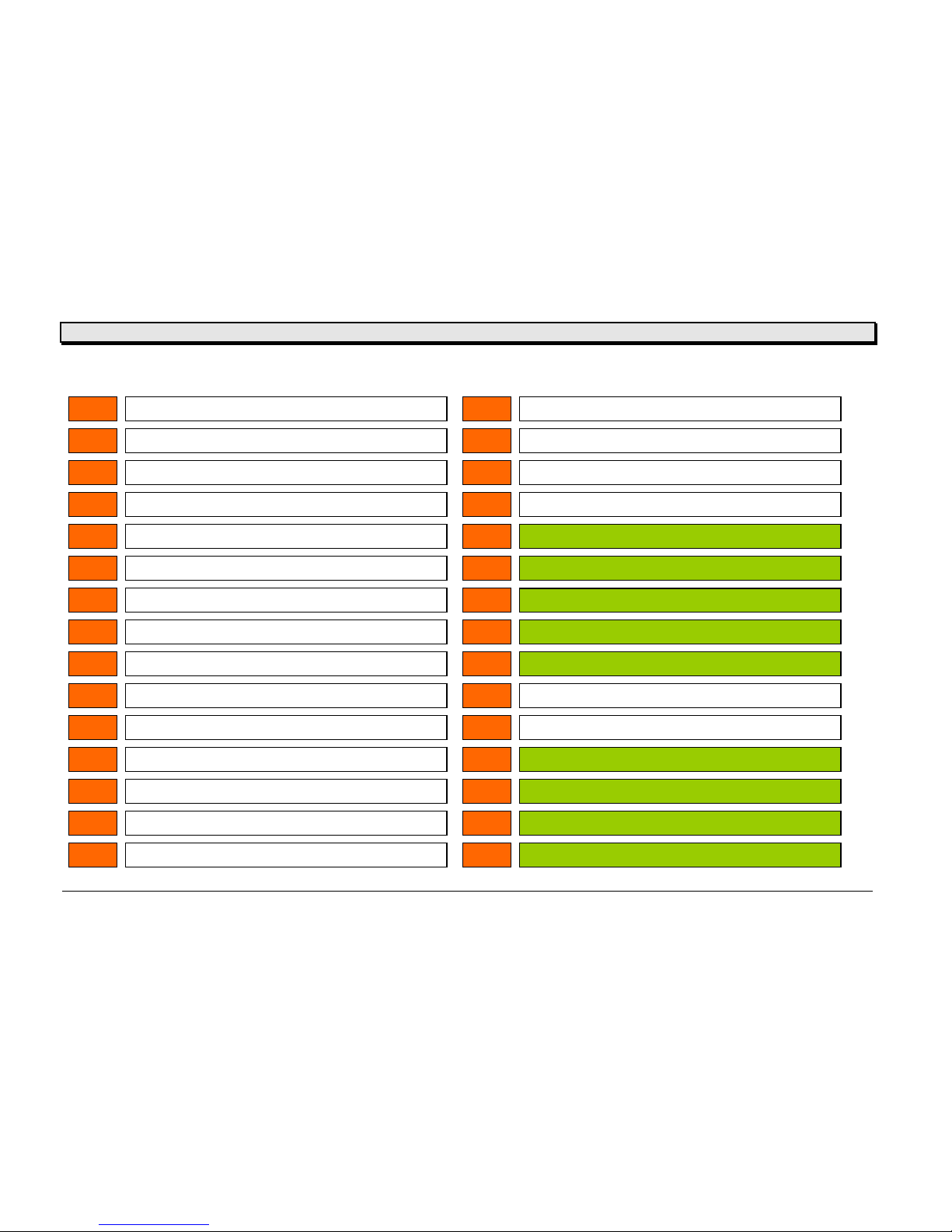
Overview - Status reports
ST 00
ST 15
head sensor not found (system will be locked)
ST 01
NOVRAM error (factory set)
ST 16
applicator home position not found
ST 02
NOVRAM write error
ST 17
dispenser pressure roller not closed
ST 03
no material in SNGL sensor
ST 18
dispenser backing paper rewinder full
ST 04
stacker full
ST 19
applicator – touch down not found
ST 05
material end
ST 20
EASY PLUG wrong command (imedeate)
ST 06
printhead overheated
ST 21
EASY PLUG wrong command between #ER and #Q
ST 07
ribbon end
ST 22
EASY PLUG command without #ER
ST 08
gap not found
ST 23
EASY PLUG not known command
ST 09
ST 24
receive error RS 232
ST 10
ramcard error
ST 25
spooler overflow
ST 11
ramcard error
ST 26
EASY PLUG wrong size or print adjustment
ST 12
ST 27
EASY PLUG counter overflow
ST 13
barcode reading error or media broken for rewinder
ST 28
EASY PLUG field outside print area
ST 14
cut sensor not found, dispenser second feeder, nothing
ST 29
EASY PLUG logo number doesn’t exist
Page 16
User / Service Manual Power Stacker
10/06 Rev. 1.09 16
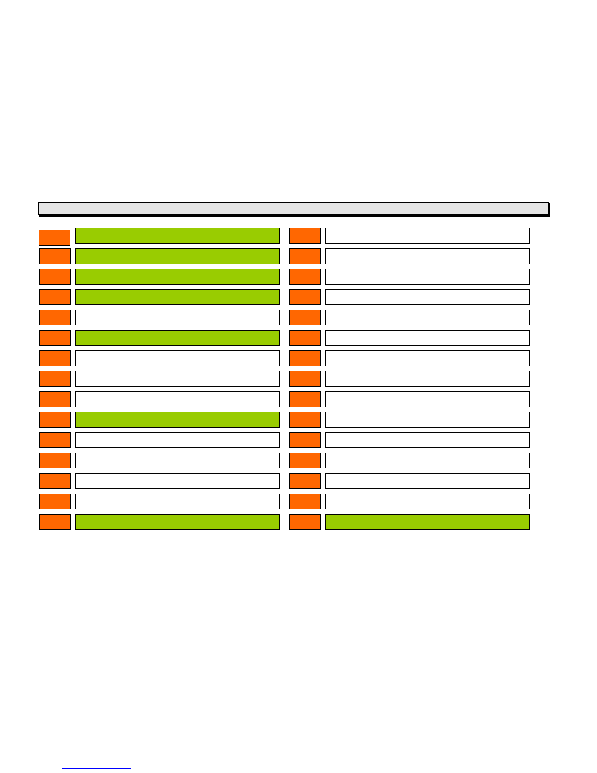
ST 30
EASY PLUG logo buffer to small
ST 45
ST 31
EASY PLUG logo number error
ST 46
ST 32
EASY PLUG postbarcode not OK
ST 47
ST 33
EASY PLUG range command #PA to #IM wrong
ST 48
ST 34
COLOR PANEL color code not found
ST 49
ST 35
COLOR PANEL logo does not fit to the card
ST 50
no read of scanner
ST 36
COLOR PANEL color card not found or programmable
ST 51
scanner not programmable (system will be locked)
ST 37
ST 52
stacker full (standard)
ST 38
ST 53
ST 39
EASY PLUG speedo error
ST 54
ST 40
receive error RS 232
ST 55
ST 41
receive error RS 232
ST 56
ST 42
ST 57
ST 43
ST 58
ST 44
ID matrix barcode error
ST 59
acess denied for setting printer to zero
Page 17
User / Service Manual Power Stacker
10/06 Rev. 1.09 17
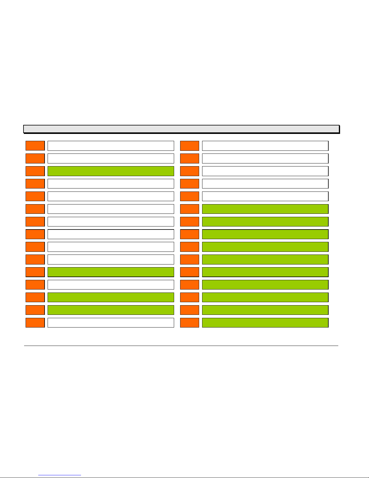
ST 60
memory allocation error (system will be locked)
ST 75
ST 61
font allocation error (system will be locked)
ST 76
ST 62
update or numberfield overflow
ST 77
ST 63
ST 78
ST 64
ST 79
ST 65
ST 80
EASY CARD wrong name of file in #FO command
ST 66
ST 81
EASY CARD field number not found
ST 67
ST 82
EASY CARD syntax of #YT or #YB command wrong
ST 68
wrong board installed for selected peripherie option
ST 83
EASY CARD number of data field to big
ST 69
interrupt error (system stands)
ST 84
EASY CARD quantity of variable characters = 0
ST 70
TDI stepper does not respond
ST 85
EASY CARD no card found
ST 71
headstrobe checksum wrong (system will be locked)
ST 86
DATA BASE not enough space for index file
ST 72
speedo system error
ST 87
DATA BASE no possibility to build index file
ST 73
speedo scaling wrong
ST 88
DATA BASE no possibility to sort index file
ST 74
ST 89
DATA BASE barcode onformation nor found in
Page 18
User / Service Manual Power Stacker
10/06 Rev. 1.09 18
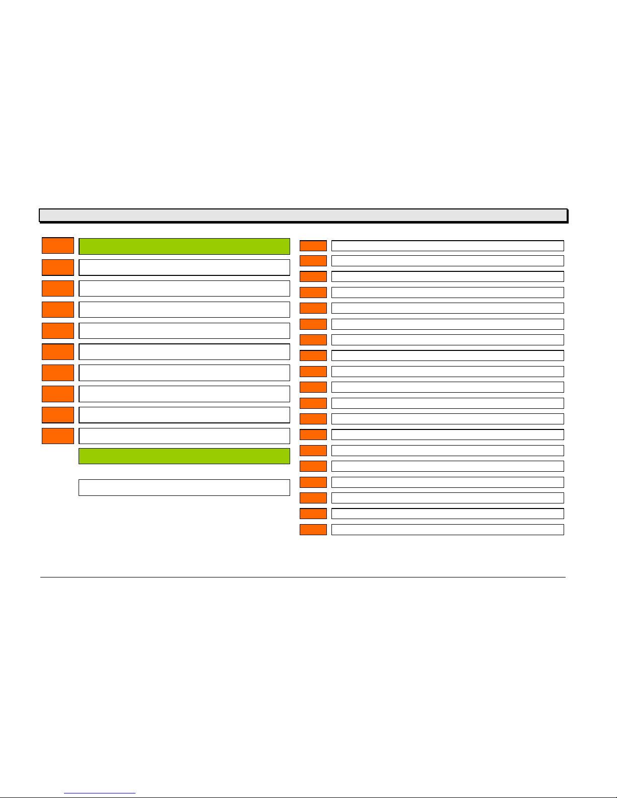
ST 90
database contains identical records
ST 91
barcode not readable
ST 92
ST 93
ST 94
ST 95
ST 96
EASY CARD undefined error
ST 97
EASY PLUG undefined error
ST 98
INTERFACE undefined error
ST 99
SYSTEM undefined derror
just warning – self confirming
must be confirmed by the user
POFF
FAIL
SCAN
OPEN
LOC
K
DAT
A
STOP
SNGL
WAIT
HOST
INIT
DOWN
UP
.LDR
.EMU
.SYS
SORT
----
LOAD
Power OFF
–
p
rinter is switched OFF
Image card could not be formatted
Scanner was unable to decode the information
cover open –switch is open
the printer is locked
data receive mode
p
rinter in STOP mode
p
rinter in single start mode
p
rinter in wait condition
p
rinter stopped by host
p
rinter is initialised
TDI table goes u
p
TDI table goes down
p
rinter in loader mode
p
rinter in emulation mode
p
rinter in system mode
data base information is sorted
p
rinter was switched on to early after power down
barcodes loaded from card
Page 19
User / Service Manual Power Stacker
10/06 Rev. 1.09 19
Maintenance, cleaning and service
Maintenance and cleaning
Clean as a standard printer – sometimes the sensor should be cleaned from paper dust.
Service
Service parts of the power stacker are – CPU board, micro switch, reflex sensor and maybe
the stepper motor.
CPU board
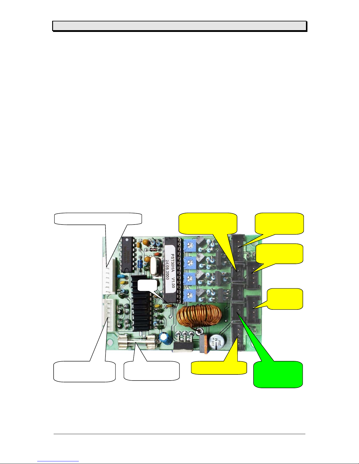
The used board in the power stacker is an intelligent board – holding a CPU with the
necessary program. The power stacker is working on it’s on.
Below you will find a picture of the CPU board showing the connector placing.
Stepper motor
JP1
Sensor 2
CN 1
Sensor 3 CN 2
Sensor 4
CN 4
Sensor 1
CN 3
Limit switch
(stacker full)
CN 6
Connection TDI J1
X3
Fuse F1
2 AT
Group switch
CN 7
Page 20
User / Service Manual Power Stacker
10/06 Rev. 1.09 20
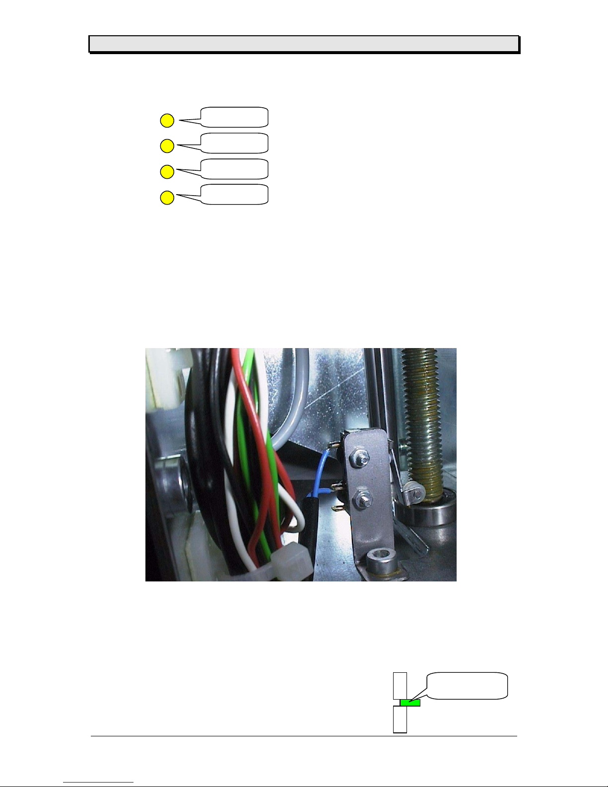
The sensor pairs placed in the front plate are numbered as following
Micro switch
The micro switch (lower end position) can be removed after the cover of the power stacker is
removed and the wire is removed from the CPU board.
Reflex Sensor
The sensor pairs are glued into the front plate ( with Loctite ....) and a special part. If one of
the sensor is defect it has to be removed carefully, the hole has the be cleaned and the new
sensor glued in.
Attention: The sensor has to stay 1 mm behind the front plate.
sensor 1mm
behind the plate
sensor 1
sensor 2
sensor 3
sensor 4
Page 21
User / Service Manual Power Stacker
10/06 Rev. 1.09 21
Stepper motor
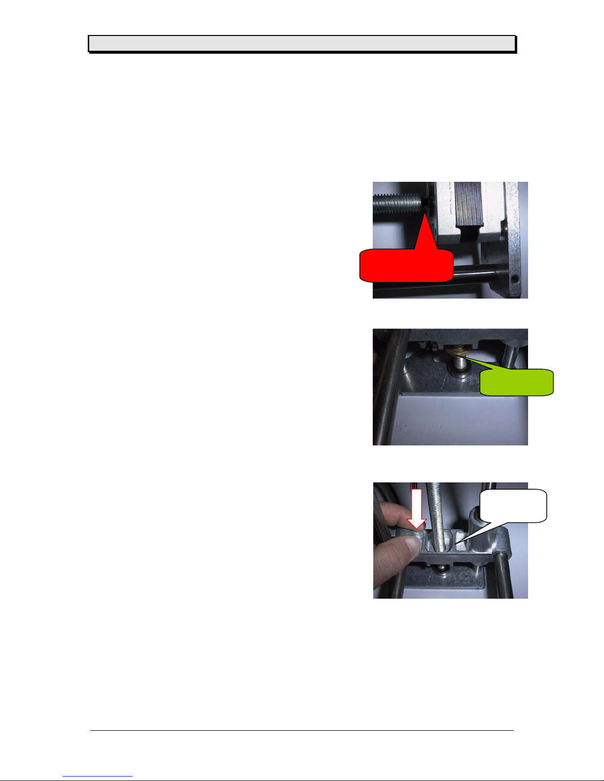
The stepper motor – if mounted to the power stacker – is an assembly and can not be
removed separately (motor and threading axle).
Assembly is like described in the TDI manual (platform).
• remove rear cover
• remove board and carrier
• disassemble platform mechanic
• open lower plate
• remove nut from thread axle
• remove platform block
• open motor screw (2) and remove
motor together with axle
• clean new motor and axle with
Aceton
• glue motor and axle together with
Loctite 648 – and assemble immediate
• position hexagonal nut around 20 mm
from the end of the axle
• move mechanic in vertical position and
press the threading axle down
• the glue is ready after 30 minutes – but
the mechanic can be assembled immediate
min. 20 mm
glue with
L
octite 648
press
do
wn
Page 22

User / Service Manual Power Stacker
10/06 Rev. 1.09 22
Diagrams
Page 23
User / Service Manual Power Stacker
10/06 Rev. 1.09 23
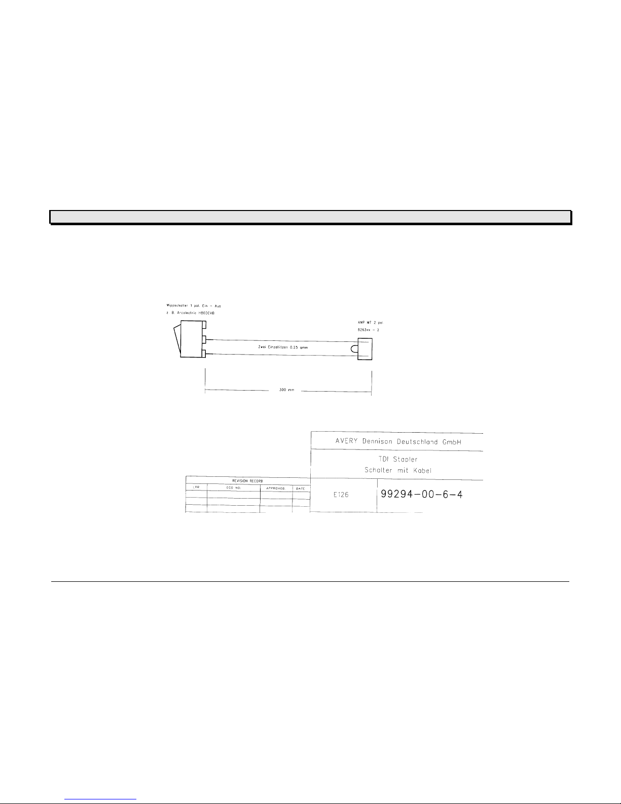
Cable drawings
Page 24
User / Service Manual Power Stacker
10/06 Rev. 1.09 24
Page 25
User / Service Manual Power Stacker
10/06 Rev. 1.09 25
Page 26
User / Service Manual Power Stacker
10/06 Rev. 1.09 26
Page 27
User / Service Manual Power Stacker
10/06 Rev. 1.09 27
Circuit diagram CPU board
Title
Number RevisionSize
A4
Date: 19-Oct-2000 Sheet of
File: Drawn By:
TDI-Stapler 99297-02-0
Aschenneller Fr.
1/1
RC3
14
RC2
13
RC1
12
RC0
11
OSC2
10
OSC1
9
VSS
8
RA5
7
RA4
6
RA3
5
RA2
4
RA1
3
RA0
2
MCLR
1
RC4
15
RC5
16
RC6
17
RC7
18
VSS
19
VDD
20
RB0
21
RB1
22
RB2
23
RB3
24
RB4
25
RB5
26
RB6
27
RB7
28
IC1
PIC16C62B/72A
X1
20MHz
R1
330R
R2
33K
D1
1N4148
1
2
3
4
CN1
1
2
3
4
CN2
1
2
3
4
CN3
1
2
3
4
CN4
1
2
CN5
1
2
CN6
D2
BAT49
C
13
IN1OUT
2
IC3A CD4066B
C
5
IN4OUT
3
IC3B CD4066B
Vin
1
Output
2
GND
3
Feedback
4
ON/OF
5
IC4
LM2576T5.0
RC
1
C2
2
VR2
3
Phase2
4
GND5GND
6
VMM2
7
MA2
8
VBB2
9
E2
10
MB2
11
MB1
12
E1
13
VBB1
14
MA1
15
VMM1
16
GND17GND
18
Phase1
19
VR1
20
C1
21
VCC
22
IC5
PBL3772
D3
BYV27
D4
BYV27
D5
BYV27D6BYV27
R11 0R51
R12
0R51
R7
1K
R9
1K
R8
1R0/0.5W
R10
1R0/0.5W
R6
15K
R3
390R
D7
BYW29-200
L1
C5
10u
C6
3n3
C7
680pC8680p
C4
220u/25V
C3 1u
R14
3R3
R13
3R3
R15
3R3
R16
3R3
R21
15K
R22
1K5
R23
1K5
R24
1K5
1
2
CN7
C1 22p
C2 22p
F1
2AT
R17
1K5
R18
1K5
R19
1K5
R20
1K5
VCC
VCC
VCCVCC
VCC
VCC
Q1
BC557
Q2
BC557
Q3
BC557
Q4
BC557
C
6
IN8OUT
9
IC3C
CD4066B
C
12
IN11OUT
10
IC3D
CD4066B
VCC
1
2
3
4
5
6
7
8
J1
1
2
3
4
JP1
CON4
C9
1,2uF
Q5
BD676
Q6
BD676
Q7
BD676
Q8
BD676
R4
2K
R5
2K
R25
2K
R26
2K
R27
100R
R28
100R
R29
100R
R30
100R
R31
680R
R32
680R
R33
680R
R34
680R
R35
680R
R36
680R
R37
680R
R38
680R
CB1
100nF
VCC
CB2
100nF
VCC
R41
6K8
R40
6K8
R39
6K8
R42
6K8
VCC
VCC
VCC
VCC
R43
4K7
VCC
Z99297-02-0SE.cdr
Page 28
User / Service Manual Power Stacker
10/06 Rev. 1.09 28
Component diagram CPU board
Page 29
User / Service Manual Power Stacker
10/06 Rev. 1.09 29
Spare parts list
Part Number : 99300-xx-0
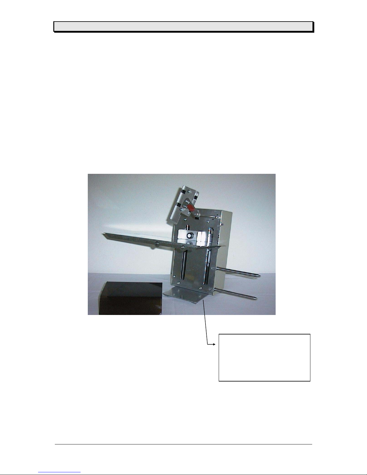
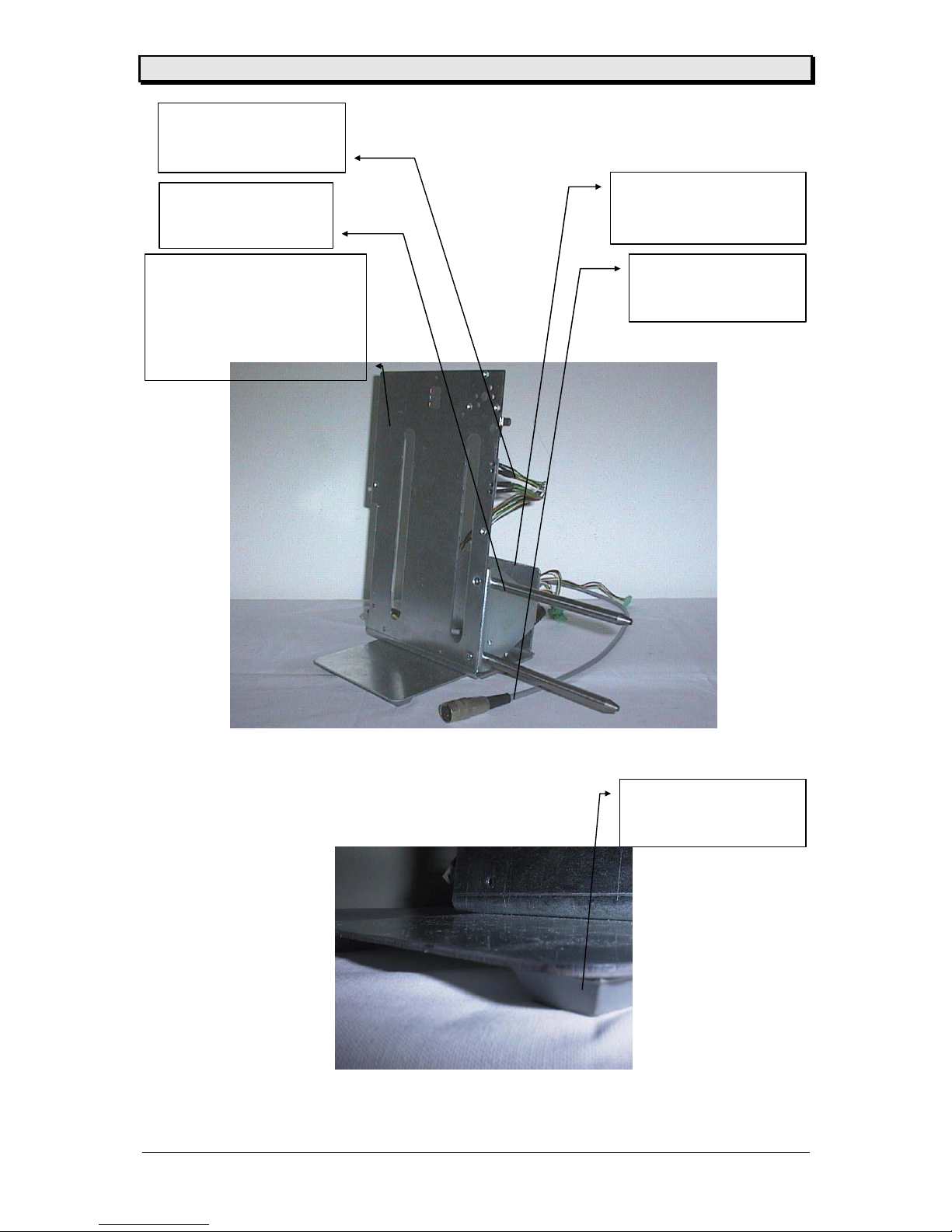
C0066 (Jumbo Stacker)
C0826 (Power Stacker TDI 1050)
Bezeichnung : Power Stacker komplett
Identification : power stacker
Page 30
User / Service Manual Power Stacker
10/06 Rev. 1.09 30
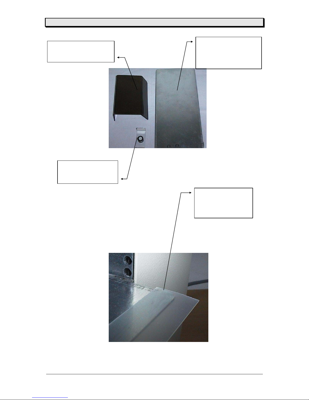
Part Number : 99722-xx-0
C0831 (TDI 1050)
Bezeichnung : Abstreifer 2
Identification : seperator 2
Part Number : 99296-xx-0
Bezeichnung : Anschlag
Identification : stopper
Part Number : 99723-xx-0
C0829 (TDI 1050)
Bezeichnung : ZSB Plattform
Identification : platform assy.
Part Number : 99678-xx-0
Bezeichnung : ZSB Abdeckung
Identification : cover assy.
Page 31
User / Service Manual Power Stacker
10/06 Rev. 1.09 31
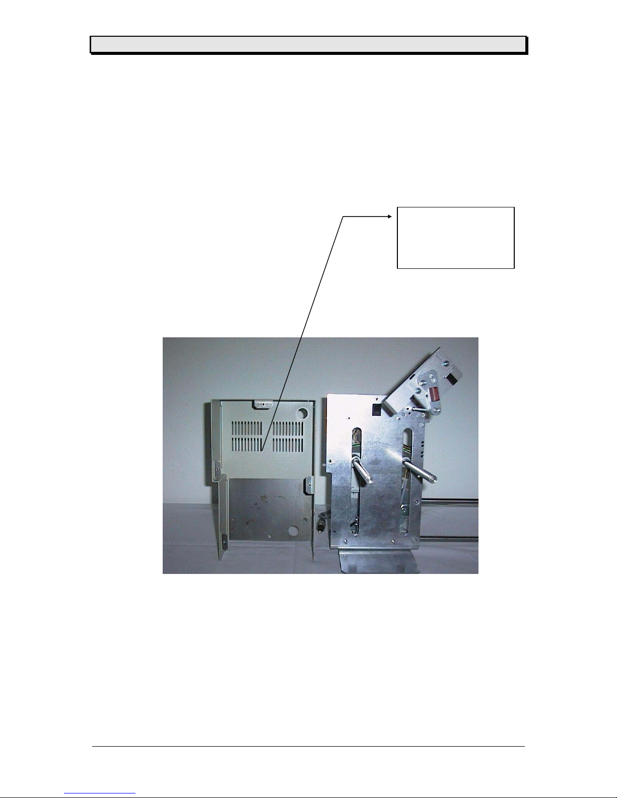
Part Number : 99299-xx-0
C0070 (Jumbo Stacker)
Bezeichnung : Rückhaube
Identification : rear cover
Page 32
User / Service Manual Power Stacker
10/06 Rev. 1.09 32
Part Number : 99302-xx-0
C0081 (Jumbo Stacker)
Bezeichnung : ZSB Boden- und
Frontplatte
Identification : front- and
bottemplate assy.
Part Number :99291 -xx-0
Bezeichnung : Achse
Identification : axle
Part Number : 98211-xx-0
Bezeichnung : Reflex Sensor
Identification : reflex sensor
Part Number : A2128
Bezeichnung : Rundkabel
Identification : Round cable
Part Number : 99303-xx-0
Bezeichnung : Anschluß
Identification : connecting part
Part Number : 92395-00-3
Bezeichnung : Gehäusefuß
Identification : rubber feet
Page 33
User / Service Manual Power Stacker
10/06 Rev. 1.09 33
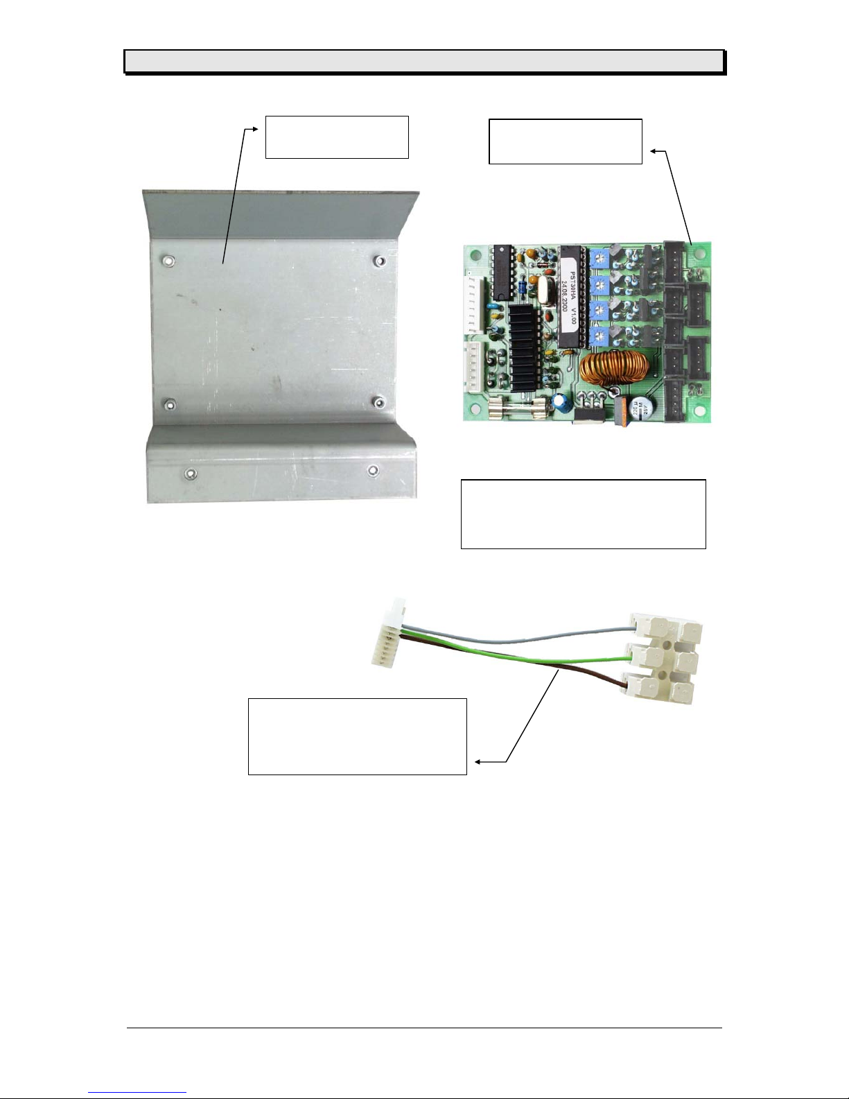
Part Number : 99297
Designation : CPU board
Part Number : 99295
Designation: Steel plate
Part Number : A2273
Designation : Round cable
(Adapter cable for connecting the new
board to an old Power Stacker)
Part Number : A2299
Designation : Upgrade-Kit Power Stacker
(A2299 = A2273 + 99297)
Page 34
User / Service Manual Power Stacker
10/06 Rev. 1.09 34
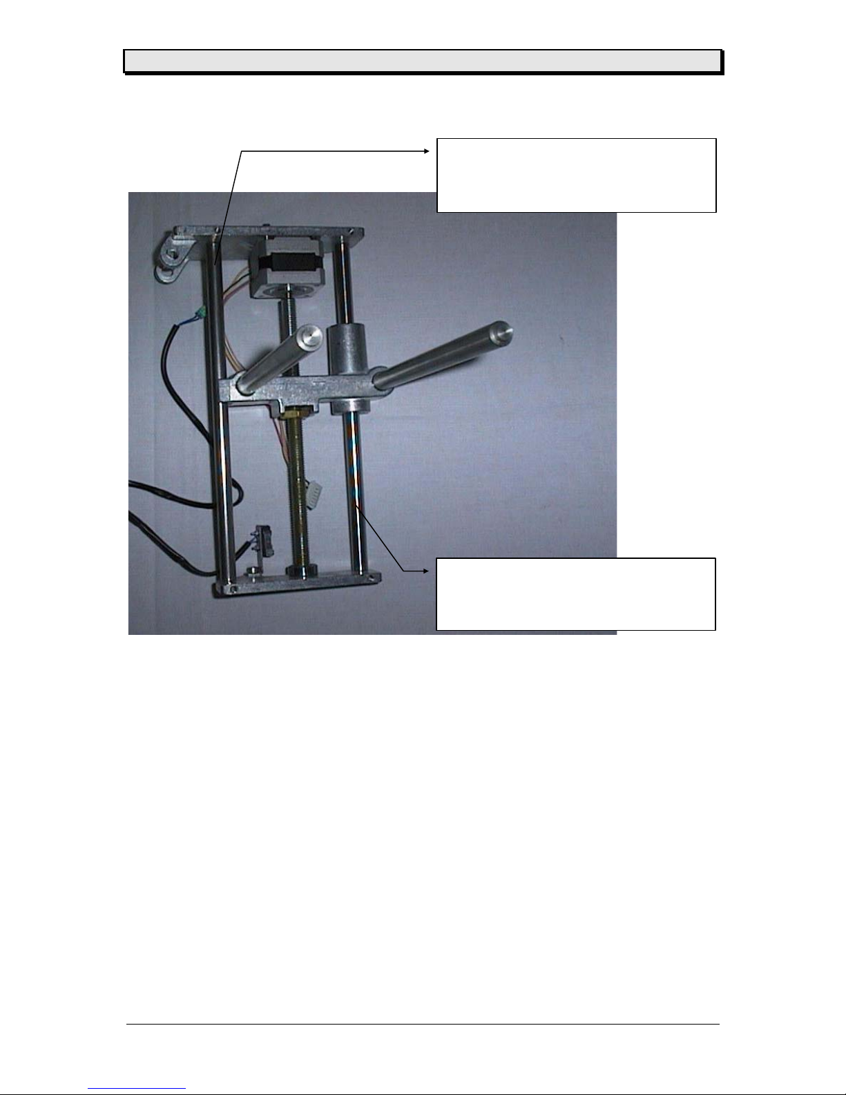
Part Number :98280
C0072 (Jumbo Stacker)
Bezeichnung : Säule TDI
Identification : Column TDI
Part Number :99176
C0073 (Jumbo Stacker)
Bezeichnung : Säule 2
Identification : Column 2
Page 35
User / Service Manual Power Stacker
10/06 Rev. 1.09 35
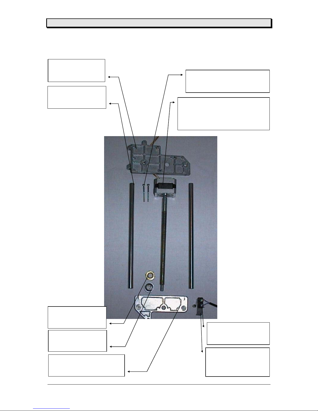
Part Number : 94763-00-3
Bezeichnung : Microschalter
Identification : micro switch
Part Number : 98293-xx-0
Bezeichnung : Schalterblech
Identification : switch mounting
part
Part Number : 98279-xx-0
Bezeichnung : Mutter
Identification : nut
Part Number : 98725-xx-0
Bezeichnung : Kugellager
Identification :
gear
Part Number : 98954-xx-0
Bezeichnung : Platte unten
Identification : lower plate
Part Number : 98280-xx-0
Bezeichnung : Säule
Identification : guding axle
Part Number : 98296-xx-0
Bezeichnung : Platte oben
Identification : upper plate
Part Number : A1701-xx
Bezeichnung : Motor mit Spindel für PowerStacker ZSB
Identification : Motor with spindle for power
stacker ass.
Part Number : M 3 x 3,5
Bezeichnung : Innensechskant Schraube
Identification : hexagonal screw
Page 36
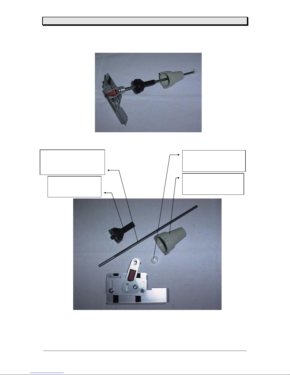
User / Service Manual Power Stacker
10/06 Rev. 1.09 36
Part Number : 98247-xx-0
Bezeichnung : ZSB Nabe
Identification : hub assy.
Part Number : 99293-xx-0
C0827 (Power Stacker TDI 1050)
Bezeichnung : Achse 2
Identification : axle 2
Part Number : 98240-xx-0
Bezeichnung : Gehäuse
Identification : cover
Part Number : 98579-xx-0
Bezeichnung : Schnellbefestiger
Identification : security part
Page 37
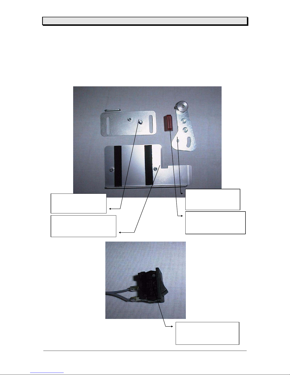
User / Service Manual Power Stacker
10/06 Rev. 1.09 37
Part Number : 99294-xx-0
Bezeichnung : Schalter mit Kabel
Identification : switch with wire
Part Number : 98846-xx-0
Bezeichnung : Griff
Identification : handle
Part Number : 99292-xx-0
Bezeichnung : ZSB Nabe
Identification : lever assy.
Part Number : 99388-xx-0
Bezeichnung : ZSB Distanzblech
Identification : distanz part assy.
Part Number : 99307-xx-0
Bezeichnung : Führung
Identification : guiding
Page 38
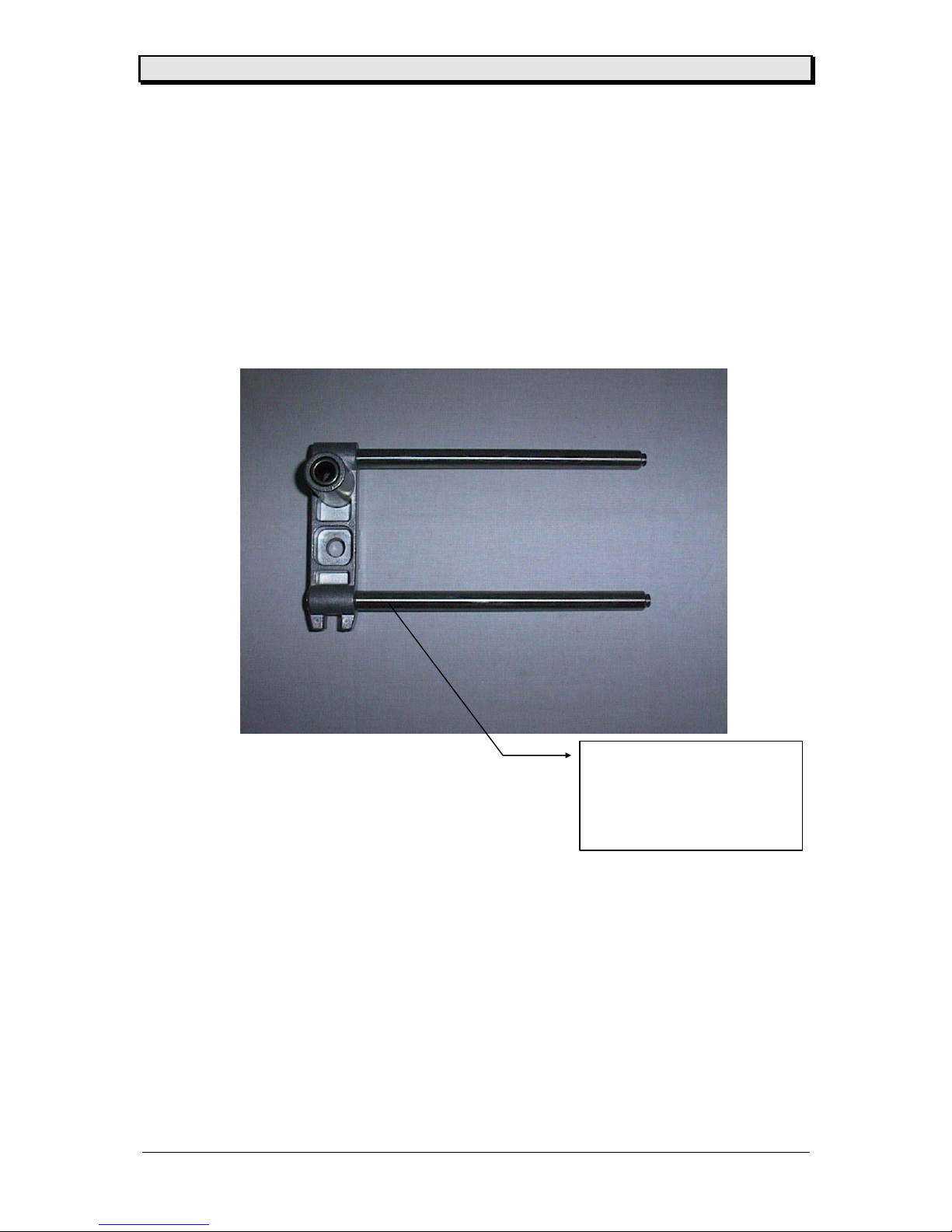
User / Service Manual Power Stacker
10/06 Rev. 1.09 38
Part Number : 98361-xx-0
C0484 (Power Stacker TDI 1050)
Bezeichnung : ZSB Schlitten
Identification : moving part assy.
Page 39

User / Service Manual Power Stacker
10/06 Rev. 1.09 39
Index
A
Activate sensor...................................... 9
Adjust label length...............................10
Assemble light cover ............................. 7
C
Cable drawings....................................23
Copyright...............................................3
CPU board.....................................19, 20
Circuit diagram............................27
Component diagram.................... 28
I
Index....................................................39
M
Magazine full ....................................... 11
Maintenance and cleaning................... 19
Micro switch.........................................20
Mount the option to the TDI ...................6
P
Parameter menu TDI ...........................12
Power Stackdr, Assemble the................5
Power stacker full.................................14
R
Reflex sensor.......................................20
S
Service.................................................19
Spare Parts Listd .................................29
ST 04 ...................................................14
Status printout......................................13
Status reports.......................................14
Stepper motor......................................21
U
Unpacking..............................................4
 Loading...