

Page 1
Monarch
Printers
9825®
•
9855®
•
9860ä
•
®
TC9800PM Rev. DJ 12/07 ©1996 Paxar Americas, Inc. a subsidiary of Avery Dennison Corp. All rights reserved.
Page 2

Each product and program carries a respective written warranty, the only warranty on
which the customer can rely. Paxar reserves the right to make changes in the product,
the programs, and their availability at any time and without notice. Although Paxar has
made every effort to provide complete and accurate information in this manual, Paxar
shall not be liable for any omissions or inaccuracies. Any update will be incorporated in
a later edition of this manual.
©1996 Paxar Americas, Inc. a subsidiary of Avery Denison Corp. All rights reserved.
No part of this publication may be reproduced, transmitted, stored in a retrieval system,
or translated into any language in any form by any means, without the prior written
permission of Paxar Americas, Inc.
WARNING
This equipment has been tested and found to comply with the limits for a Class A digital device,
pursuant to Part 15 of the FCC Rules. These limits are designed to provide reasonable protection
against harmful interference when the equipment is operated in a commercial environment. This
equipment generates, uses, and can radiate radio frequency energy and, if not installed and used in
accordance with the instruction manual, may cause harmful interference to radio communications.
Operation of this equipment in a residential area is likely to cause harmful interference in which case
the user will be required to correct the interference at his own expense.
CANADIAN D.O.C. WARNING
This digital apparatus does not exceed the Class A limits for radio noise emissions from digital
apparatus set out in the Radio Interference Regulations of the Canadian Department of
Communications.
Le présent appareil numérique n’émet pas de bruits radioélectriques dépassant les limites
applicables aux appareils numériques de la classe A prescrites dans le Réglement sur le brouillage
radioélectrique édicte par le ministPre des Communications du Canada.
Trademarks
Monarch® and 9800 are registered trademarks of Paxar Americas, Inc.
MONARCH LANGUAGE INTERPRETER, MLI, MonarchNet2, 7410, 926, 928, 932, 935, 939, 939i, 9825, 9855, and 9860
are trademarks of Paxar Americas, Inc.
Paxar® is a trademark of Paxar Corporation.
Avery Dennison® is a trademark of Avery Dennison Corporation.
Microsoft, Windows, and NT are trademarks of Microsoft Corporation.
Novell and NetWare are trademarks of Novell, Inc. in the United States and other countries.
HP Jet Admin and HP Web Jet Admin are trademarks of Hewlett-Packard, Inc.
Hewlett-Packard is a registered trademark of Hewlett-Packard, Inc.
Centronics is a registered trademark of Centronics Data Computer Corporation.
Adobe and Acrobat are trademarks of Adobe Systems Incorporated.
EPCglobal, Inc.™ and Electronic Product Code™ (EPC) are trademarks of Uniform Code Council, Inc.
UFST, Monotype, the Monotype logo, and CG Triumvirate are trademarks of Monotype Imaging, Inc.
Avery Dennison Printer Systems Division
170 Monarch Lane
Miamisburg, OH 45342
Page 3

TABLE OF CONTENTS
GETTING STARTED. . . . . . . . . . . . . . . . . . . . . . . . . . . . . . . . . . . . . . . . . . . . . . . . . . . . . 1-1
About This Manual . . . . . . . . . . . . . . . . . . . . . . . . . . . . . . . . . . . . . . . . . . . . . . . 1-1
Before You Begin . . . . . . . . . . . . . . . . . . . . . . . . . . . . . . . . . . . . . . . . . . . . . . . . 1-2
Creating an MPCLII Format Packet . . . . . . . . . . . . . . . . . . . . . . . . . . . . . . . . . . 1-2
Daily Startup Procedures . . . . . . . . . . . . . . . . . . . . . . . . . . . . . . . . . . . . . . . . . 1-4
Starting with a Design. . . . . . . . . . . . . . . . . . . . . . . . . . . . . . . . . . . . . . . . . . . . . 1-5
Determining Format Contents . . . . . . . . . . . . . . . . . . . . . . . . . . . . . . . . . . . . . . 1-6
Determining the Print Area. . . . . . . . . . . . . . . . . . . . . . . . . . . . . . . . . . . . . . . . . 1-6
Drawing Rough Sketches. . . . . . . . . . . . . . . . . . . . . . . . . . . . . . . . . . . . . . . . . . 1-7
Using Supply Layout Grids. . . . . . . . . . . . . . . . . . . . . . . . . . . . . . . . . . . . . . . . . 1-8
Considering Field Types . . . . . . . . . . . . . . . . . . . . . . . . . . . . . . . . . . . . . . . . . . . 1-9
Considering Fonts. . . . . . . . . . . . . . . . . . . . . . . . . . . . . . . . . . . . . . . . . . . . . . . 1-10
Interchanging Packets . . . . . . . . . . . . . . . . . . . . . . . . . . . . . . . . . . . . . . . . . . . 1-10
Using the Format Worksheet . . . . . . . . . . . . . . . . . . . . . . . . . . . . . . . . . . . . . . 1-10
Filling in the Format Worksheet . . . . . . . . . . . . . . . . . . . . . . . . . . . . . 1-10
CONFIGURING THE PRINTER . . . . . . . . . . . . . . . . . . . . . . . . . . . . . . . . . . . . . . . . . . . . 2-1
Setting Communication Parameters . . . . . . . . . . . . . . . . . . . . . . . . . . . . . . . . . 2-2
Using Parallel Communications . . . . . . . . . . . . . . . . . . . . . . . . . . . . . . . . . . . . . 2-2
MPCLII Punctuation . . . . . . . . . . . . . . . . . . . . . . . . . . . . . . . . . . . . . . . 2-3
Standard Syntax Guidelines . . . . . . . . . . . . . . . . . . . . . . . . . . . . . . . . 2-3
Using Online Configuration Packets. . . . . . . . . . . . . . . . . . . . . . . . . . . . . . . . . . 2-5
Configuration Packet Header. . . . . . . . . . . . . . . . . . . . . . . . . . . . . . . . 2-5
Configuration Syntax Guidelines . . . . . . . . . . . . . . . . . . . . . . . . . . . . . 2-8
i
Page 4

Making Print Adjustments . . . . . . . . . . . . . . . . . . . . . . . . . . . . . . . . . . . . . . . . . 2-8
Defining the System Setup Packet . . . . . . . . . . . . . . . . . . . . . . . . . . . . . . . . . . 2-9
Defining the Supply Setup Packet . . . . . . . . . . . . . . . . . . . . . . . . . . . . . . . . . . 2-11
Defining the Print Control Packet. . . . . . . . . . . . . . . . . . . . . . . . . . . . . . . . . . . 2-13
Defining the Monetary Formatting Packet . . . . . . . . . . . . . . . . . . . . . . . . . . . . 2-14
Defining the Control Characters Packet . . . . . . . . . . . . . . . . . . . . . . . . . . . . . 2-15
Resetting Control Characters . . . . . . . . . . . . . . . . . . . . . . . . . . . . . . 2-17
Using Immediate Commands . . . . . . . . . . . . . . . . . . . . . . . . . . . . . . 2-17
Defining the Communication Settings Packet . . . . . . . . . . . . . . . . . . . . . . . . . 2-21
Defining the Backfeed Control Packet . . . . . . . . . . . . . . . . . . . . . . . . . . . . . . . 2-22
Special Considerations When Using Backfeed . . . . . . . . . . . . . . . . 2-24
Defining the Memory Configuration Packet. . . . . . . . . . . . . . . . . . . . . . . . . . . 2-25
Checking Current Buffer Sizes . . . . . . . . . . . . . . . . . . . . . . . . . . . . . 2-27
About Memory Buffers . . . . . . . . . . . . . . . . . . . . . . . . . . . . . . . . . . . . . . . . . . . 2-27
Buffer Worksheet. . . . . . . . . . . . . . . . . . . . . . . . . . . . . . . . . . . . . . . . 2-30
Buffer Allocation Considerations . . . . . . . . . . . . . . . . . . . . . . . . . . . . 2-30
Memory Considerations with Downloaded TrueType Fonts . . . . . . . 2-31
Formatting Flash Memory . . . . . . . . . . . . . . . . . . . . . . . . . . . . . . . . . . . . . . . . 2-32
Flash Memory Guidelines . . . . . . . . . . . . . . . . . . . . . . . . . . . . . . . . . . . . . . . . 2-32
Clearing Packets from Memory . . . . . . . . . . . . . . . . . . . . . . . . . . . . . . . . . . . . 2-33
Using the Font Packet . . . . . . . . . . . . . . . . . . . . . . . . . . . . . . . . . . . . . . . . . . . 2-34
Uploading Format Header Information . . . . . . . . . . . . . . . . . . . . . . . . . . . . . . 2-38
Defining a Verifier Configuration Packet . . . . . . . . . . . . . . . . . . . . . . . . . . . . . 2-39
Defining a Network Console Packet . . . . . . . . . . . . . . . . . . . . . . . . . . . . . . . . 2-40
ii
Page 5

DEFINING FIELDS . . . . . . . . . . . . . . . . . . . . . . . . . . . . . . . . . . . . . . . . . . . . . . . . . . . . . . 3-1
Defining the Format Header . . . . . . . . . . . . . . . . . . . . . . . . . . . . . . . . . . . . . . . . 3-2
Defining Text Fields. . . . . . . . . . . . . . . . . . . . . . . . . . . . . . . . . . . . . . . . . . . . . . . 3-3
Defining Bar Code Fields . . . . . . . . . . . . . . . . . . . . . . . . . . . . . . . . . . . . . . . . . . 3-8
Defining Non-Printable Text Fields . . . . . . . . . . . . . . . . . . . . . . . . . . . . . . . . . . 3-19
Defining Constant Text Fields. . . . . . . . . . . . . . . . . . . . . . . . . . . . . . . . . . . . . . 3-20
Defining Line Fields . . . . . . . . . . . . . . . . . . . . . . . . . . . . . . . . . . . . . . . . . . . . . 3-25
Line Types . . . . . . . . . . . . . . . . . . . . . . . . . . . . . . . . . . . . . . . . . . . . . 3-25
Defining Box Fields. . . . . . . . . . . . . . . . . . . . . . . . . . . . . . . . . . . . . . . . . . . . . . 3-27
Defining Verifier Fields . . . . . . . . . . . . . . . . . . . . . . . . . . . . . . . . . . . . . . . . . . . 3-30
Defining the RFID Data Field . . . . . . . . . . . . . . . . . . . . . . . . . . . . . . . . . . . . . . 3-31
DEFINING FIELD OPTIONS . . . . . . . . . . . . . . . . . . . . . . . . . . . . . . . . . . . . . . . . . . . . . . 4-1
Applying Field Options . . . . . . . . . . . . . . . . . . . . . . . . . . . . . . . . . . . . . . . . . . . . 4-2
Combining Field Options . . . . . . . . . . . . . . . . . . . . . . . . . . . . . . . . . . . 4-2
Applying Options to the RFID Data Field . . . . . . . . . . . . . . . . . . . . . . . . . . . . . . 4-3
Option 1 (Fixed Data) . . . . . . . . . . . . . . . . . . . . . . . . . . . . . . . . . . . . . . . . . . . . . 4-4
Option 2 (Data Type Restrictions). . . . . . . . . . . . . . . . . . . . . . . . . . . . . . . . . . . .
Option 3 (Data Entry Templates) . . . . . . . . . . . . . . . . . . . . . . . . . . . . . . . . . . . .
4-5
4-6
Option 4 (Copy Data) . . . . . . . . . . . . . . . . . . . . . . . . . . . . . . . . . . . . . . . . . . . . . 4-7
Merging Fields . . . . . . . . . . . . . . . . . . . . . . . . . . . . . . . . . . . . . . . . . . . 4-9
Sub-Fields . . . . . . . . . . . . . . . . . . . . . . . . . . . . . . . . . . . . . . . . . . . . . . 4-9
Option 5 (Define Data Entry Sources) . . . . . . . . . . . . . . . . . . . . . . . . . . . . . . . 4-10
Option 6 (Upload Field Data) . . . . . . . . . . . . . . . . . . . . . . . . . . . . . . . . . . . . . . 4-11
Sample Upload Packet . . . . . . . . . . . . . . . . . . . . . . . . . . . . . . . . . . . 4-12
Option 20 (Define Data Entry Prompts) . . . . . . . . . . . . . . . . . . . . . . . . . . . . . . 4-13
Option 21 (Define Extended Field Names) . . . . . . . . . . . . . . . . . . . . . . . . . . . 4-14
Option 30 (Pad Data) . . . . . . . . . . . . . . . . . . . . . . . . . . . . . . . . . . . . . . . . . . . . 4-14
Sample Use for Padding . . . . . . . . . . . . . . . . . . . . . . . . . . . . . . . . . . 4-15
iii
Page 6

Option 31 (Calculate Check Digit) . . . . . . . . . . . . . . . . . . . . . . . . . . . . . . . . . 4-15
Option 42 (Price Field). . . . . . . . . . . . . . . . . . . . . . . . . . . . . . . . . . . . . . . . . . . 4-16
Option 50 (Bar Code Density) . . . . . . . . . . . . . . . . . . . . . . . . . . . . . . . . . . . . . 4-17
Option 51 (PDF417 Security/Truncation) . . . . . . . . . . . . . . . . . . . . . . . . . . . . . 4-19
Option 52 (PDF417 Width/Length) . . . . . . . . . . . . . . . . . . . . . . . . . . . . . . . . . 4-20
Option 60 (Incrementing/Decrementing Fields). . . . . . . . . . . . . . . . . . . . . . . . 4-21
Fixing the First Number in the Incrementing Sequence . . . . . . . . . . 4-21
Option 61 (Reimage Field) . . . . . . . . . . . . . . . . . . . . . . . . . . . . . . . . . . . . . . . 4-22
Option 62 (Bypass Bar Code) . . . . . . . . . . . . . . . . . . . . . . . . . . . . . . . . . . . . . 4-23
Verifier Information . . . . . . . . . . . . . . . . . . . . . . . . . . . . . . . . . . . . . . 4-24
Using Check Digits. . . . . . . . . . . . . . . . . . . . . . . . . . . . . . . . . . . . . . . . . . . . . . 4-25
Sum of Products Calculation. . . . . . . . . . . . . . . . . . . . . . . . . . . . . . . 4-26
Sum of Digits Calculation . . . . . . . . . . . . . . . . . . . . . . . . . . . . . . . . . 4-27
CREATING GRAPHICS . . . . . . . . . . . . . . . . . . . . . . . . . . . . . . . . . . . . . . . . . . . . . . . . . . 5-1
Overview of Compliance Labels . . . . . . . . . . . . . . . . . . . . . . . . . . . . . . . . . . . . 5-2
Overview of Bitmapped Images . . . . . . . . . . . . . . . . . . . . . . . . . . . . . . . . . . . . 5-3
Determining a Method. . . . . . . . . . . . . . . . . . . . . . . . . . . . . . . . . . . . . 5-3
Designing Compliance Labels. . . . . . . . . . . . . . . . . . . . . . . . . . . . . . . . . . . . . . 5-4
Designing Bitmapped Images . . . . . . . . . . . . . . . . . . . . . . . . . . . . . . . . . . . . . . 5-4
Special Considerations . . . . . . . . . . . . . . . . . . . . . . . . . . . . . . . . . . . . 5-4
Using the Hex Method. . . . . . . . . . . . . . . . . . . . . . . . . . . . . . . . . . . . . 5-5
Using the Run Length Encoding Method . . . . . . . . . . . . . . . . . . . . . . 5-7
Determining How to Store the Image . . . . . . . . . . . . . . . . . . . . . . . . . . . . . . . . 5-9
Using Flash . . . . . . . . . . . . . . . . . . . . . . . . . . . . . . . . . . . . . . . . . . . . . 5-9
Using Volatile RAM . . . . . . . . . . . . . . . . . . . . . . . . . . . . . . . . . . . . . . 5-10
Using Temporary Storage . . . . . . . . . . . . . . . . . . . . . . . . . . . . . . . . . 5-10
Creating a Graphic Packet. . . . . . . . . . . . . . . . . . . . . . . . . . . . . . . . . . . . . . . . 5-11
Positioning the Graphic Image . . . . . . . . . . . . . . . . . . . . . . . . . . . . . 5-11
iv
Page 7

Defining the Graphic Header . . . . . . . . . . . . . . . . . . . . . . . . . . . . . . . . . . . . . . 5-13
Creating Bitmap Fields . . . . . . . . . . . . . . . . . . . . . . . . . . . . . . . . . . . . . . . . . . . 5-15
Creating Next-Bitmap Fields . . . . . . . . . . . . . . . . . . . . . . . . . . . . . . . . . . . . . . 5-16
Creating Duplicate Fields . . . . . . . . . . . . . . . . . . . . . . . . . . . . . . . . . . . . . . . . . 5-17
Sample Compliance Graphic Packet . . . . . . . . . . . . . . . . . . . . . . . . . . . . . . . . 5-18
Sample Hex Graphic Packet . . . . . . . . . . . . . . . . . . . . . . . . . . . . . . . . . . . . . . 5-19
Sample Run Length Graphic Packet . . . . . . . . . . . . . . . . . . . . . . . . . . . . . . . . 5-20
Placing the Graphic in a Format . . . . . . . . . . . . . . . . . . . . . . . . . . . . . . . . . . . . 5-22
Defining the Graphic Field . . . . . . . . . . . . . . . . . . . . . . . . . . . . . . . . . . . . . . . . 5-22
Sample Compliance Label . . . . . . . . . . . . . . . . . . . . . . . . . . . . . . . . . . . . . . . . 5-24
Sample Bitmap Graphic Image . . . . . . . . . . . . . . . . . . . . . . . . . . . . . . . . . . . . 5-25
PRINTING . . . . . . . . . . . . . . . . . . . . . . . . . . . . . . . . . . . . . . . . . . . . . . . . . . . . . . . . . . . . . 6-1
Downloading Files . . . . . . . . . . . . . . . . . . . . . . . . . . . . . . . . . . . . . . . . . . . . . . . 6-2
Defining the Batch Header . . . . . . . . . . . . . . . . . . . . . . . . . . . . . . . . . . . . . . . . . 6-3
Defining the Batch Control Field. . . . . . . . . . . . . . . . . . . . . . . . . . . . . . . . . . . . . 6-4
Defining Batch Data Fields . . . . . . . . . . . . . . . . . . . . . . . . . . . . . . . . . . . . . . . . . 6-8
Using Expanded EPC Gen2 RFID Data. . . . . . . . . . . . . . . . . . . . . . . . . . . . . . . 6-9
Using Special Characters in Batch Data . . . . . . . . . . . . . . . . . . . . . . . . . . . . . 6-11
Merged or Sub-Fields . . . . . . . . . . . . . . . . . . . . . . . . . . . . . . . . . . . . 6-12
Incrementing Fields . . . . . . . . . . . . . . . . . . . . . . . . . . . . . . . . . . . . . . 6-12
Special Printing Considerations . . . . . . . . . . . . . . . . . . . . . . . . . . . . . . . . . . . . 6-12
9855 Printer . . . . . . . . . . . . . . . . . . . . . . . . . . . . . . . . . . . . . . . . . . . . 6-12
9855 RFID Printer . . . . . . . . . . . . . . . . . . . . . . . . . . . . . . . . . . . . . . . 6-12
9860 Printer . . . . . . . . . . . . . . . . . . . . . . . . . . . . . . . . . . . . . . . . . . . . 6-12
Serial Bar Code Printing Information. . . . . . . . . . . . . . . . . . . . . . . . . 6-13
Downloading Methods . . . . . . . . . . . . . . . . . . . . . . . . . . . . . . . . . . . . . . . . . . . 6-13
Sequential Method. . . . . . . . . . . . . . . . . . . . . . . . . . . . . . . . . . . . . . . 6-13
Batch Method. . . . . . . . . . . . . . . . . . . . . . . . . . . . . . . . . . . . . . . . . . . 6-14
Batch Quantity Zero Method . . . . . . . . . . . . . . . . . . . . . . . . . . . . . . . 6-14
Optional Entry Method . . . . . . . . . . . . . . . . . . . . . . . . . . . . . . . . . . . . 6-15
Creating DOS Batch Files for Downloading . . . . . . . . . . . . . . . . . . . . . . . . . . . 6-15
v
Page 8

STATUS POLLING. . . . . . . . . . . . . . . . . . . . . . . . . . . . . . . . . . . . . . . . . . . . . . . . . . . . . . 7-1
Inquiry Request (ENQ) . . . . . . . . . . . . . . . . . . . . . . . . . . . . . . . . . . . . . . . . . . . 7-2
Inquiry Response . . . . . . . . . . . . . . . . . . . . . . . . . . . . . . . . . . . . . . . . 7-2
ENQ Reference Table - Byte #2. . . . . . . . . . . . . . . . . . . . . . . . . . . . . . . . . . . . . 7-4
ENQ Reference Table - Byte #3. . . . . . . . . . . . . . . . . . . . . . . . . . . . . . . . . . . . . 7-6
Job Request. . . . . . . . . . . . . . . . . . . . . . . . . . . . . . . . . . . . . . . . . . . . . . . . . . . . 7-8
Job Response . . . . . . . . . . . . . . . . . . . . . . . . . . . . . . . . . . . . . . . . . . . 7-9
Job Status 0, 1, 2 Response Table (Status 1 Codes) . . . . . . . . . . . . 7-13
Job Status 0, 1, 2 Response Table (Status 2 Codes) . . . . . . . . . . . . 7-14
Status Polling Considerations for Script Mode . . . . . . . . . . . . . . . . . . . . . . . . 7-15
DIAGNOSTICS AND ERRORS . . . . . . . . . . . . . . . . . . . . . . . . . . . . . . . . . . . . . . . . . . . . 8-1
Printing a Test Label. . . . . . . . . . . . . . . . . . . . . . . . . . . . . . . . . . . . . . . . . . . . . . 8-2
Reading a Test Label . . . . . . . . . . . . . . . . . . . . . . . . . . . . . . . . . . . . . . . . . . . . . 8-2
If You Receive an Error Message . . . . . . . . . . . . . . . . . . . . . . . . . . . . 8-3
Reading an Error Label . . . . . . . . . . . . . . . . . . . . . . . . . . . . . . . . . . . . . . . . . . . 8-3
If the PC and Printer Are Not Communicating . . . . . . . . . . . . . . . . . . 8-4
Calling Technical Support . . . . . . . . . . . . . . . . . . . . . . . . . . . . . . . . . . 8-5
Additional Diagnostics Information . . . . . . . . . . . . . . . . . . . . . . . . . . . . . . . . . . 8-5
Data Errors. . . . . . . . . . . . . . . . . . . . . . . . . . . . . . . . . . . . . . . . . . . . . . . . . . . . . 8-6
Communication Failures . . . . . . . . . . . . . . . . . . . . . . . . . . . . . . . . . . . . . . . . . 8-15
Data Formatting Failures . . . . . . . . . . . . . . . . . . . . . . . . . . . . . . . . . . . . . . . . . 8-17
Machine Faults. . . . . . . . . . . . . . . . . . . . . . . . . . . . . . . . . . . . . . . . . . . . . . . . . 8-19
PRINTER OPTIMIZATION . . . . . . . . . . . . . . . . . . . . . . . . . . . . . . . . . . . . . . . . . . . . . . . . 9-1
Adjusting the Print Quality . . . . . . . . . . . . . . . . . . . . . . . . . . . . . . . . . . . . . . . . . 9-1
Reducing Imaging Time. . . . . . . . . . . . . . . . . . . . . . . . . . . . . . . . . . . . . . . . . . . 9-3
General Format Tips and Hints . . . . . . . . . . . . . . . . . . . . . . . . . . . . . . . . . . . . . 9-4
vi
Page 9

SAMPLES. . . . . . . . . . . . . . . . . . . . . . . . . . . . . . . . . . . . . . . . . . . . . . . . . . . . . . . . . . . . . A-1
Sample UPCA Format Packet . . . . . . . . . . . . . . . . . . . . . . . . . . . . . . . . . . . . . . A-2
Sample MaxiCode Packets . . . . . . . . . . . . . . . . . . . . . . . . . . . . . . . . . . . . . . . . A-3
Mode 0 (Obsolete) Sample . . . . . . . . . . . . . . . . . . . . . . . . . . . . . . . . . A-4
Mode 2 Sample . . . . . . . . . . . . . . . . . . . . . . . . . . . . . . . . . . . . . . . . . . A-5
Mode 3 Sample . . . . . . . . . . . . . . . . . . . . . . . . . . . . . . . . . . . . . . . . . . A-6
MaxiCode Compression Sample. . . . . . . . . . . . . . . . . . . . . . . . . . . . . A-7
Sample Data Matrix Packets . . . . . . . . . . . . . . . . . . . . . . . . . . . . . . . . . . . . . . . A-8
Square Data Matrix Packet . . . . . . . . . . . . . . . . . . . . . . . . . . . . . . . . . A-8
Rectangular Data Matrix Packet . . . . . . . . . . . . . . . . . . . . . . . . . . . . . A-8
Sample Quick Response Packets . . . . . . . . . . . . . . . . . . . . . . . . . . . . . . . . . . . A-9
Entering Batch Data for QR Code . . . . . . . . . . . . . . . . . . . . . . . . . . . A-10
QR Code Packet . . . . . . . . . . . . . . . . . . . . . . . . . . . . . . . . . . . . . . . . A-11
Structured Append Mode. . . . . . . . . . . . . . . . . . . . . . . . . . . . . . . . . . A-11
Structured Append QR Code Packet. . . . . . . . . . . . . . . . . . . . . . . . . A-12
Sample Compliance Packet . . . . . . . . . . . . . . . . . . . . . . . . . . . . . . . . . . . . . . . A-13
Sample Format Packet . . . . . . . . . . . . . . . . . . . . . . . . . . . . . . . . . . . . . . . . . . A-16
Sample Data Entry Format Packet . . . . . . . . . . . . . . . . . . . . . . . . . . . . . . . . . A-18
RFID Data Field Samples. . . . . . . . . . . . . . . . . . . . . . . . . . . . . . . . . . . . . . . . . A-19
96-Bit RFID Data Field Samples . . . . . . . . . . . . . . . . . . . . . . . . . . . . A-20
Expanded C1Gen2 Samples . . . . . . . . . . . . . . . . . . . . . . . . . . . . . . . A-25
vii
Page 10

FONTS
. . . . . . . . . . . . . . . . . . . . . . . . . . . . . . . . . . . . . . . . . . . . . . . . . . . . . . . . . . . . . . .
B-1
EFF Swiss Bold Font. . . . . . . . . . . . . . . . . . . . . . . . . . . . . . . . . . . . . . B-4
PaxarSymbols Font 56 Characters . . . . . . . . . . . . . . . . . . . . . . . . . . . B-4
Paxar Font 70 and Font 71 Characters. . . . . . . . . . . . . . . . . . . . . . . . B-4
NAFTA Font 72 and Font 73 Characters. . . . . . . . . . . . . . . . . . . . . . . B-5
Bitmap Font Information. . . . . . . . . . . . . . . . . . . . . . . . . . . . . . . . . . . . . . . . . . . B-5
Monospaced Font Magnification . . . . . . . . . . . . . . . . . . . . . . . . . . . . . . . . . . . . B-6
Using 203 DPI. . . . . . . . . . . . . . . . . . . . . . . . . . . . . . . . . . . . . . . . . . . B-6
Using 300 DPI. . . . . . . . . . . . . . . . . . . . . . . . . . . . . . . . . . . . . . . . . . . B-6
Proportional Font Magnification . . . . . . . . . . . . . . . . . . . . . . . . . . . . . . . . . . . . B-10
CG Triumvirate Typeface Bold (9 pt.) 203 DPI. . . . . . . . . . . . . . . . B-10
Height Magnification 203 DPI . . . . . . . . . . . . . . . . . . . . . . . . . . . . . . B-10
CG Triumvirate Typeface Bold (9 pt.) 300 DPI. . . . . . . . . . . . . . . . B-11
Height Magnification 300 DPI . . . . . . . . . . . . . . . . . . . . . . . . . . . . . . B-11
CG Triumvirate Typeface (6 pt.) 203 DPI . . . . . . . . . . . . . . . . . . . . B-11
Height Maginfication 203 DPI . . . . . . . . . . . . . . . . . . . . . . . . . . . . . . B-12
CG Triumvirate Typeface (6 pt.) 300 DPI . . . . . . . . . . . . . . . . . . . . B-12
Height Maginfication 203 DPI . . . . . . . . . . . . . . . . . . . . . . . . . . . . . . B-12
CG Triumvirate Typeface (7 pt.) 203 DPI . . . . . . . . . . . . . . . . . . . . B-13
Height Magnification 203 DPI . . . . . . . . . . . . . . . . . . . . . . . . . . . . . . B-13
CG Triumvirate
Typeface (7 pt.) 300 DPI . . . . . . . . . . . . . . . . . . . . B-13
CG Triumvirate Typeface (9 pt.) 203 DPI . . . . . . . . . . . . . . . . . . . . B-14
CG Triumvirate Typeface (9 pt.) 300 DPI . . . . . . . . . . . . . . . . . . . . B-15
CG Triumvirate Typeface (11 pt.) 203 DPI . . . . . . . . . . . . . . . . . . . B-15
CG Triumvirate Typeface (11 pt.) 300 DPI . . . . . . . . . . . . . . . . . . . B-16
CG Triumvirate Typeface (15 pt.) 203 DPI . . . . . . . . . . . . . . . . . . . B-17
CG Triumvirate Typeface (15 pt.) 300 DPI . . . . . . . . . . . . . . . . . . . B-18
viii
Page 11

Scalable/TrueType® Font Information. . . . . . . . . . . . . . . . . . . . . . . . . . . . . . . . B-19
Format Considerations. . . . . . . . . . . . . . . . . . . . . . . . . . . . . . . . . . . . B-19
Downloading TrueType Fonts . . . . . . . . . . . . . . . . . . . . . . . . . . . . . . . . . . . . . . B-20
Using UNICODE (Double-Byte) Fonts . . . . . . . . . . . . . . . . . . . . . . . . . . . . . . . B-21
Character Mapping Overview . . . . . . . . . . . . . . . . . . . . . . . . . . . . . . B-22
UNICODE (Double-Byte) Font Sample . . . . . . . . . . . . . . . . . . . . . . . B-23
Licensing Your Fonts . . . . . . . . . . . . . . . . . . . . . . . . . . . . . . . . . . . . . . . . . . . . B-23
Using Font Numbers in Formats. . . . . . . . . . . . . . . . . . . . . . . . . . . . . . . . . . . . B-24
Locating the Font Number in a Font Packet . . . . . . . . . . . . . . . . . . . B-24
SYMBOL SETS/CODE PAGES . . . . . . . . . . . . . . . . . . . . . . . . . . . . . . . . . . . . . . . . . . . . C-1
Supported Symbol Sets and Code Pages . . . . . . . . . . . . . . . . . . . . . . . . . . . . . C-1
Using Code 128 Function Codes . . . . . . . . . . . . . . . . . . . . . . . . . . . . . . . . . . . . C-2
Entering Extended Characters . . . . . . . . . . . . . . . . . . . . . . . . . . . . . . . . . . . . . . C-2
Using International Character Sets/Code Pages . . . . . . . . . . . . . . . . . . . . . . . . C-2
Internal Symbol Set . . . . . . . . . . . . . . . . . . . . . . . . . . . . . . . . . . . . . . . C-3
ANSI Symbol Set . . . . . . . . . . . . . . . . . . . . . . . . . . . . . . . . . . . . . . . . . C-4
Bold Character Set. . . . . . . . . . . . . . . . . . . . . . . . . . . . . . . . . . . . . . . . C-4
OCRA Character Set . . . . . . . . . . . . . . . . . . . . . . . . . . . . . . . . . . . . . . C-5
Code Page 100 (Macintosh) . . . . . . . . . . . . . . . . . . . . . . . . . . . . . . . . C-5
Code Page 101 (Wingdings) . . . . . . . . . . . . . . . . . . . . . . . . . . . . . . . . C-6
Code Page 437 (Latin U.S.). . . . . . . . . . . . . . . . . . . . . . . . . . . . . . . . . C-6
Code Page 850 (Latin 1) . . . . . . . . . . . . . . . . . . . . . . . . . . . . . . . . . . . C-7
Code Page 852 (Latin 2) . . . . . . . . . . . . . . . . . . . . . . . . . . . . . . . . . . . C-7
Code Page 855 (Russian) . . . . . . . . . . . . . . . . . . . . . . . . . . . . . . . . . . C-8
Code Page 857 (IBM Turkish) . . . . . . . . . . . . . . . . . . . . . . . . . . . . . . . C-8
Code Page 860 (MS-DOS Portuguese). . . . . . . . . . . . . . . . . . . . . . . . C-9
ix
Page 12

Code Page 1250 (Latin 2) . . . . . . . . . . . . . . . . . . . . . . . . . . . . . . . . . . C-9
Code Page 1251 (Cyrillic) . . . . . . . . . . . . . . . . . . . . . . . . . . . . . . . . . C-10
Code Page 1252 (Latin 1) . . . . . . . . . . . . . . . . . . . . . . . . . . . . . . . . . C-10
Code Page 1253 (Greek) . . . . . . . . . . . . . . . . . . . . . . . . . . . . . . . . . C-11
Code Page 1254 (Turkish) . . . . . . . . . . . . . . . . . . . . . . . . . . . . . . . . . C-11
Code Page 1255 (Hebrew) . . . . . . . . . . . . . . . . . . . . . . . . . . . . . . . . C-12
Code Page 1256 (Arabic) . . . . . . . . . . . . . . . . . . . . . . . . . . . . . . . . . C-12
Code Page 1257 (Baltic) . . . . . . . . . . . . . . . . . . . . . . . . . . . . . . . . . . C-13
Code Page 1258 (Vietnamese). . . . . . . . . . . . . . . . . . . . . . . . . . . . . C-13
ASCII to Hexadecimal Conversion Chart . . . . . . . . . . . . . . . . . . . . . . . . . . . . C-14
Binary to Hex Conversion Chart . . . . . . . . . . . . . . . . . . . . . . . . . . . . . . . . . . . C-17
Dot to Run Length Encoding Chart . . . . . . . . . . . . . . . . . . . . . . . . . . . . . . . . . C-21
ON (Black) Dots . . . . . . . . . . . . . . . . . . . . . . . . . . . . . . . . . . . . . . . . C-21
OFF (White Dots) . . . . . . . . . . . . . . . . . . . . . . . . . . . . . . . . . . . . . . . C-21
FORMAT DESIGN TOOLS . . . . . . . . . . . . . . . . . . . . . . . . . . . . . . . . . . . . . . . . . . . . . . . D-1
Online Configuration Worksheet . . . . . . . . . . . . . . . . . . . . . . . . . . . . . . . . . . . . D-2
Batch Worksheet . . . . . . . . . . . . . . . . . . . . . . . . . . . . . . . . . . . . . . . . . . . . . . . . D-3
Check Digit Worksheet . . . . . . . . . . . . . . . . . . . . . . . . . . . . . . . . . . . . . . . . . . . D-4
Supply Layout (Inches) . . . . . . . . . . . . . . . . . . . . . . . . . . . . . . . . . . . . . . . . . . . D-5
Supply Layout (Metric). . . . . . . . . . . . . . . . . . . . . . . . . . . . . . . . . . . . . . . . . . . . D-6
Supply Layout (Dpi) . . . . . . . . . . . . . . . . . . . . . . . . . . . . . . . . . . . . . . . . . . . . . . D-7
Format Worksheet . . . . . . . . . . . . . . . . . . . . . . . . . . . . . . . . . . . . . . . . . . . . . . . D-9
PRINTER DIFFERENCES . . . . . . . . . . . . . . . . . . . . . . . . . . . . . . . . . . . . . . . . . . . . . . . . E-1
Printer Comparison . . . . . . . . . . . . . . . . . . . . . . . . . . . . . . . . . . . . . . . . . . . . . . E-1
Post-Print Options . . . . . . . . . . . . . . . . . . . . . . . . . . . . . . . . . . . . . . . . . . . . . . . E-3
GLOSSARY . . . . . . . . . . . . . . . . . . . . . . . . . . . . . . . . . . . . . . . . . . . . . . . . . . . . . . . . . . . G-1
x
Page 13

GETTING STARTED
Before you read this manual, review the printer information in the
Operator’s Handbook or Operating Instructions. This manual
provides the necessary information to design, write and print a
Monarch® Printer Control Language II (MPCLII) format. The
following printers support this type of format:
N
9825 (V. 1.0 or greater)
N
9855 (V. 1.0 or greater)
N
9860 (V. 1.0 or greater)
See Appendix E, "Printer Differences" for a description of each
printer’s features.
About This Manual
1
You do not need to be a programmer to use this manual, but you
must be familiar with creating text files and using basic MS-DOS®
commands. This chapter describes how to
N
create and download a sample MPCLII packet.
N
use the Supply Layout Grid and Format Worksheet.
N
categorize data into field types and select fonts to use in
your format.
See "Defining Text Fields" in Chapter 3 for a list of available fonts
for your printer. See Chapter 4, "Defining Field Options," for a list
of available options for your printer.
Getting Started
1-1
Page 14

Before You Begin
Connect the printer to the host. Refer to the Quick Reference
1.
for more information.
Load supplies in the printer. Refer to the Quick Reference for
2.
more information.
Turn on the printer.
3.
Set the communication parameters and configure the printer.
4.
The communication parameters at the printer must match
those at the host. See Chapter 2, "Configuring the Printer,"
for more information.
Design your format. See "Starting with a Design" for more
5.
information.
Download your format to the printer. See Chapter 6,
6.
"Printing," for more information.
Creating an MPCLII Format Packet
A format defines which fields appear and where the fields are
printed on the label. The printer requires this information in a
special form, using Monarch Printer Control Language II (MPCL).
This section describes how to create a sample MPCLII format
packet.
Make sure supplies are loaded, the printer is connected to the
host and is ready to receive data. Refer to the Quick Reference
for more information.
For detailed information about the format header, text, constant
text, and bar code fields, see Chapter 3, "Defining Fields." For
information about batch packets, see Chapter 6, "Printing."
Type the following format header, in any text editor:
1.
{F,25,A,R,E,200,200,"FMT-25" p
1-2
Getting Started
Page 15

Type the following constant text field:
2.
C,140,40,0,1,2,1,W,C,0,0,"SAMPLE FORMAT",0 p
Type the following bar code field:
3.
B,1,12,F,85,40,1,2,40,5,L,0 p
Type the following text field:
4.
T,2,18,V,50,50,1,3,1,1,B,L,0,0,0 p }
You have created a format packet for your MPCLII printer. Now, a
batch packet must be created before you can print the format.
Type the following batch header, after the text field line:
5.
{B,25,N,1 p
Type the following bar code data:
6.
1,"02802811111" p
Type the following text field data:
7.
2,"TEXT FIELD" p }
Save your file as SAMPLE.FMT.
8.
Type MODE COM1:9600,N,8,1 at the DOS prompt if you are
9.
using serial communications. This sets the communication
parameters at your host. These communication parameters
must match those at your printer. See "Setting
Communication Parameters," in Chapter 2, or your host’s
documentation for more information.
Getting Started
1-3
Page 16
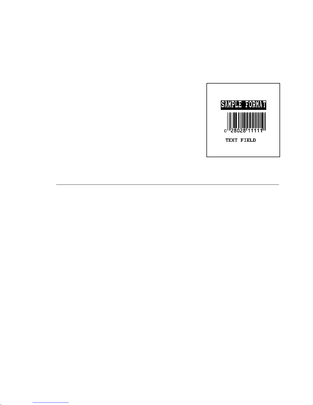
Type COPY SAMPLE.FMT COM1. The following 2 inch by 2
10.
inch label prints:
{F,25,A,R,E,200,200,"Fmt 25" p
C,140,40,0,1,2,1,W,C,0,0,"SAMPLE FORMAT",0 p
B,1,12,F,85,40,1,2,40,5,L,0 p
T,2,18,V,50,50,1,3,1,1,B,L,0,0,0 p }
Sample Batch Packet
{B,25,N,1 p
1,"02802811111" p
2,"TEXT FIELD" p }
See "Starting with a Design" to design your
format and Chapter 3, "Defining Fields" to
create text, bar code, and line fields.
Daily Startup Procedures
You may want to design a checklist for operators to follow each
day. Here are a few suggested items: Turn on the printer and
host, make sure ribbon and supplies are loaded, make sure
communication parameters are set, and download packets from
the host to the printer.
1-4
Getting Started
You may want to keep records of supplies that have been printed.
A good way to do this is to design a print log for operators to
complete at the end of the day. Here are some suggestions for
types of information to include in a print log: date, operator’s
name, format name, supply size, quantity printed, evaluation of
print quality, and problems/comments.
Keep backup copies of your format, batch data, check digit, and
graphic packets.
Page 17

Starting with a Design
Before you create a format packet, you must design your label.
There are several steps to designing a custom label:
Decide which fields should appear on your label. See
1.
"Determining Format Contents" for more information.
Determine your label size. Labels are available from Paxar in
2.
a wide variety of sizes. Your application and the amount of
data you need to print determines the supply size. Contact
your Account Manager or Technical Support for more
information.
Draw a rough sketch of your label. You may want to draw
3.
several variations to see what works best. See "Drawing
Rough Sketches" for more information.
Identify the field types that appear on your label. See
4.
"Considering Field Types" for more information.
Decide which fonts you want to use. See "Considering Fonts"
5.
for more information.
Fill out your Format Worksheet. See "Using the Format
6.
Worksheet" for more information.
At this point, you are ready to send your design to the printer. To
do this:
Create a format packet, based on how you filled out your
7.
worksheet. See Chapter 3, "Defining Fields," for more
information.
Download your format packet to the printer. See Chapter 6,
8.
"Printing," for more information.
Getting Started
1-5
Page 18
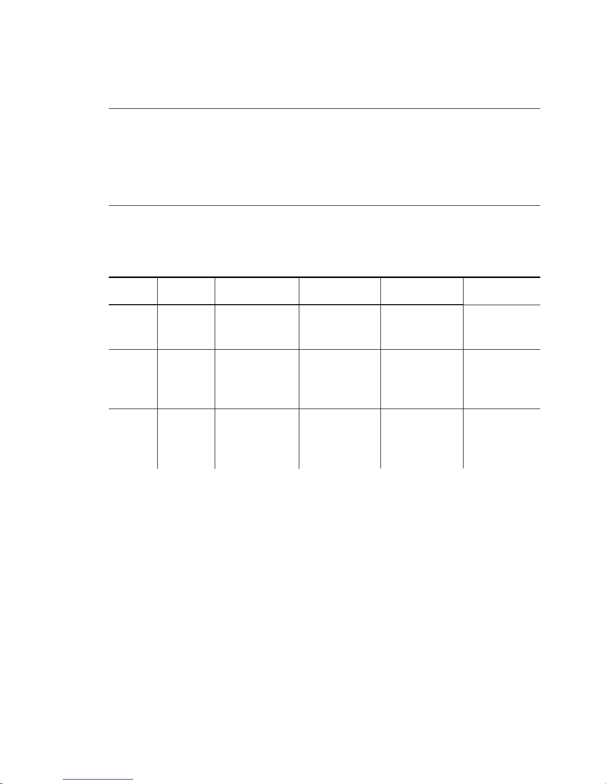
Determining Format Contents
Before you lay out your format, answer these questions. How
large is your supply, which fonts do you want to use, do you want
to include a bar code, and do you want to include graphics?
Determining the Print Area
The "bottom" (or leading edge) is the edge that exits the printer
first. The 0,0 point is at the bottom left corner of the label. The
print area is in the center of the label.
Printer Unit of
Measure
9825
9855/
9860
9855RFID
English 425 x 1750 400 x 1600 75 x 50 75 x 50
Metric 1080 x 4445 1016 x 4064 191 x 127 191 x 127
Dots (203) 863 x 3553 812 x 3248 152 x 102 152 x 102
English 425 x 1750 400 x 1600 75 x 32 75 x 32
Metric 1080 x 4445 1016 x 4064 191 x 81 191 x 81
Dots (203) 863 x 3553 812 x 3248 152 x 65 152 x 65
Dots (300) 1275 x 5250 200 x 3900 225 x 96 225 x 96
English 400 x 1300 400 x 1300 400 x 100 400 x 100
Metric 1016 x 3300 1016 x 3300 1016 x 254 1016 x 254
Dots (203) 812 x 2639 812 x 2639 812 x 203 812 x 203
Dots (300) 1200 x 3900 1200 x 3900 1200 x 300 1200 x 300
Max. Supply
(Wid x Len)
Max. Print Area
(Wid x Len)
Min. Supply
(Wid x Len)
Min. Print Area
(Wid x Len)
The following non-print zones are recommended for the printers:
All Supplies .050 inches on either edge of the label.
All Supplies .020 inches at the end of the label.
1-6
Getting Started
Page 19
If using the optional verifier, allow a minimum no-scan zone on
the trailing edge of the label of 0.5 inch (13 mm). The trailing
edge is the edge of the label that exits the printer last; regardless
of how the format is designed on the label.
Use the following formulas to convert inches to dots and metric:
Dots = inches x 203 (or 300 dots per inch)
Metric (1/10mm) = inches x 254
English (1/100 inch) = 100 x (dots/203) or (dots/300)
Dots = Metric (1/10 mm) x 799/1000 (or 1181/1000)
300 dpi depends on your printer.
Drawing Rough Sketches
After you decide what information you want to print, sketch how
you want the information to appear on the label. Note any areas
that are preprinted on the label, such as a logo.
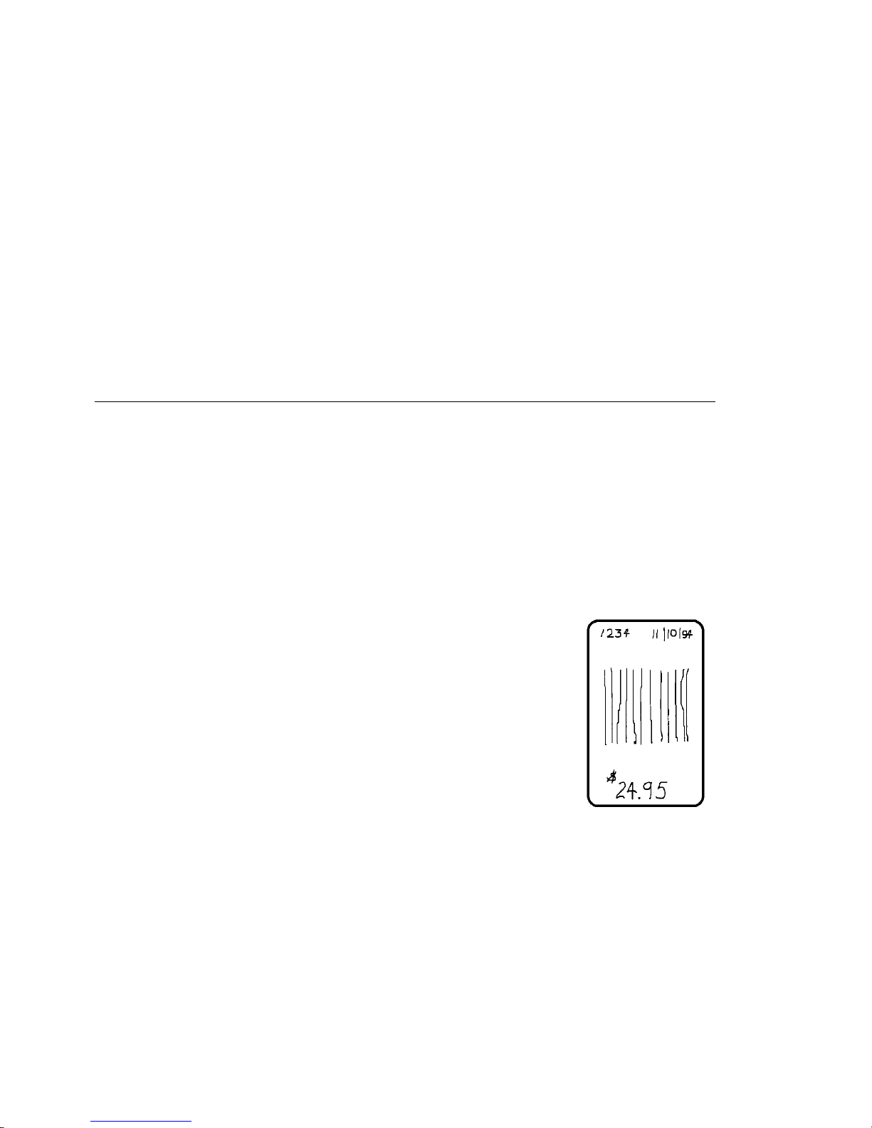
As soon as you know what information to include on the label,
and you have a rough sketch, you can use a supply layout grid to
help you layout and size your label. If you do not want to use a
grid, go to "Considering Field Types" to choose what information
you want on your label.
Getting Started
1-7
Page 20
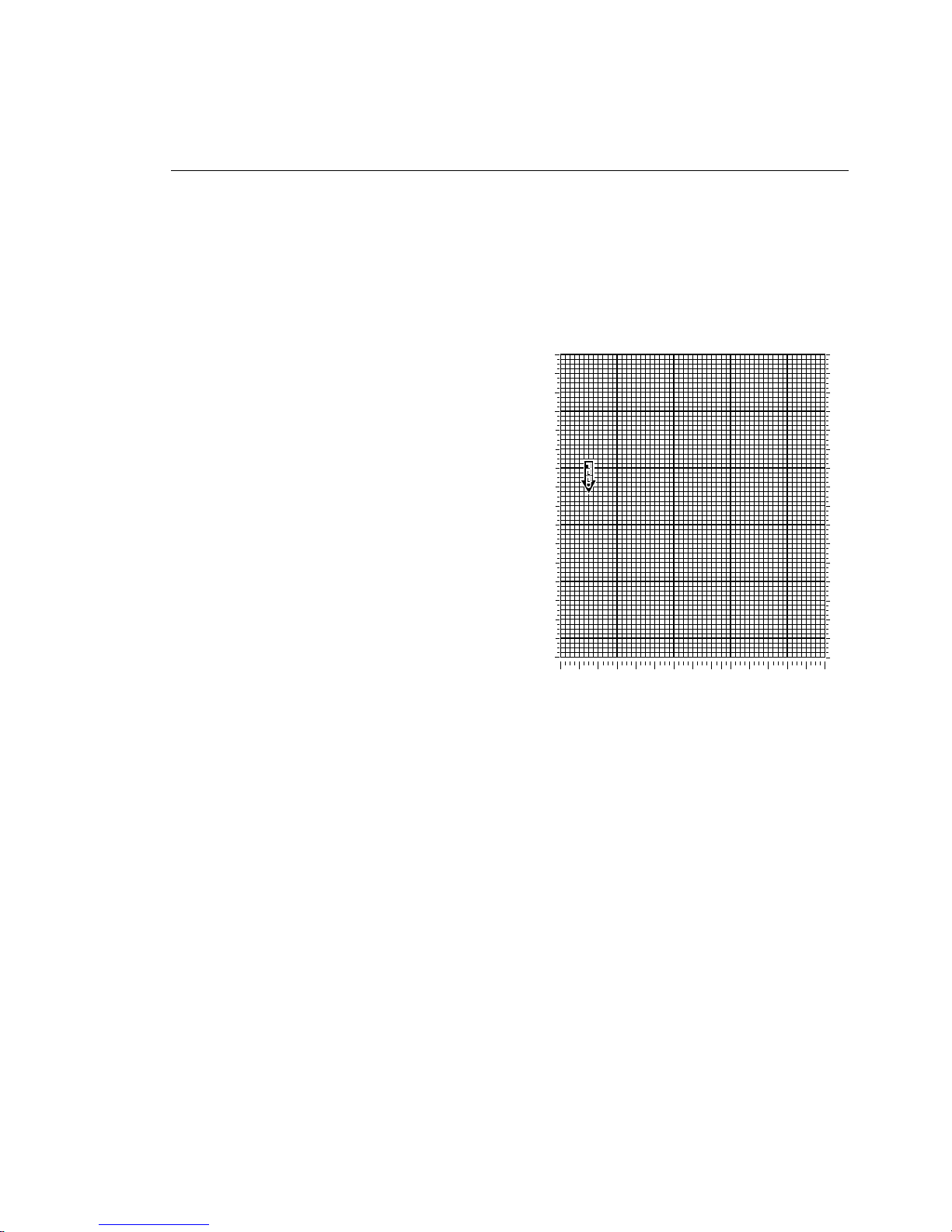
Using Supply Layout Grids
A supply layout grid contains measurement markers. These
markers help you accurately position information on your label.
Decide whether you want to design formats using English, Metric,
or Dot measurements. Choose from the following grids:
N
English
The English grid, shown to the
right, is measured in 1/100
inches.
N
Metric
The Metric grid is measured in
1/10 millimeters (mm).
N
Graphic
The printer uses dots to print
images on a label. The
printhead has 203 dots per inch
203 300
1624
1523
1421
1320
1218
1117
1015
914
812
711
609
508
406
305
203
102
0.0
102
203
0.0
203
300
300
150
0.0
305
406
450
600
Supply Layout (dpi)
508 609
711
750
812
900
1050
1200
853
1350 1500 1650 1800 1950 2100
(dpi) or an optional 300 dots per
inch printhead depending on
your printer.
Choose English or Metric units when designing formats to use
with different printers. English or Metric units allow more direct
use of formats on printers with different density printheads.
2400
2250
2100
1950
1800
1650
1500
1350
1200
1050
900
750
600
450
300
150
0.0
If you want to use supply layout grids, a copy of each is in
Appendix D, "Format Design Tools."
1-8
Getting Started
Page 21
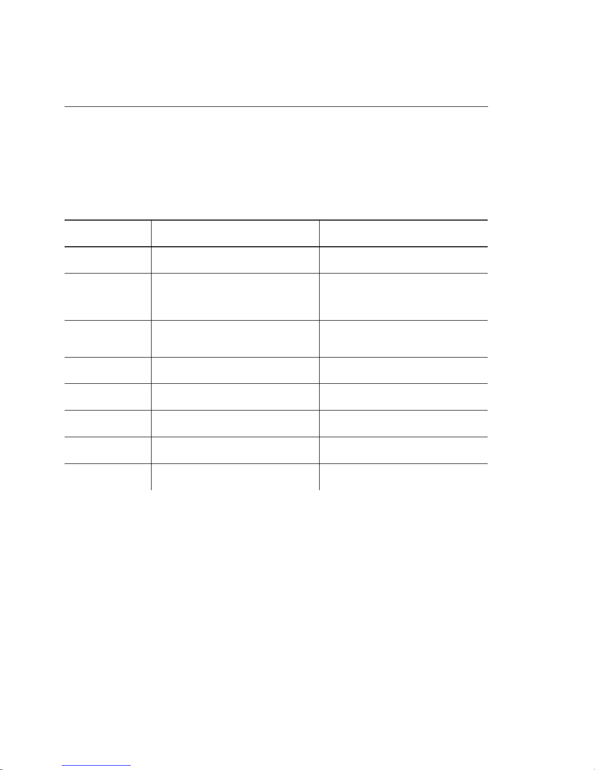
Considering Field Types
After you select a supply size, the next step in designing a format
is to decide what information you want to print on the label. For
example, you may want to print your company name, price of an
item, and a bar code that combines information from other places.
Everything you need to print falls into one of the following
categories.
Field Type Description Examples
Text Contains letters, numbers, or
symbols you need to print.
Non-Printable
Te x t
Bar Code Used for printing bar codes that
Constant Text Prints fixed characters that print
Line or Box Highlights or separates items. line marking out the regular price,
Graphic Contains a bitmap image or a
Verifier Specifies a verifier configuration
RFID Contains the RFID data you need
Holds data for use later, such as
for merging into another field.
The printer does not print
non-printable text fields.
can be scanned.
without changing.
compliance label overlay.
to use for each format.
to program into the RFID tag.
item number, item description,
department number, price, date
city, state, and zip code to be
included in a bar code
item or serial numbers, zip codes,
information you don’t want to
have visible to customers
company name, company address
border around the supply
logos
mode 2, mode 19
Class 1 Gen1, Class 1 Gen2, EPC
data
All of the above field types except graphics are discussed in
Chapter 3. See Chapter 5, "Creating Graphics," for information
on including graphics in your format.
Getting Started
1-9
Page 22

Considering Fonts
When working with fonts, you have three considerations: font
appearance, font size (scalable or bitmapped), and font spacing
(monospaced or proportional).
The TrueType® scalable font, EFF Swiss Bold (font 50) is
standard on the printers. See Appendix B, "Fonts," for samples of
each font.
Interchanging Packets
You can use an MPCLII format that was designed for another
MPCLII printer on a 9800 series printer. However, the format may
appear smaller (fields will be shorter), because most of the 9800
series printers use a 203 dpi printhead. The 9855 and 9860
printers have an optional 300 dpi printhead.
Using the Format Worksheet
The Format Worksheet is divided into sections that list the field
types. Each section has boxes to fill in with parameters that
define your format. A format worksheet is included in Appendix
D, "Format Design Tools."
Filling in the Format Worksheet
Decide what type of field to use on your label.
Make a copy of the Format Worksheet.
1.
Define the Format Header.
2.
Define all non-printable text fields before you define the ones
3.
you want to print. See "Defining Non-Printable Text Fields" in
Chapter 3 for more information.
Define options as you require them. See Chapter 4, "Defining
4.
Field Options" for more information.
1-10
Getting Started
Page 23

CONFIGURING THE PRINTER
This chapter discusses how to
N
set communication parameters.
N
upload the printer’s configuration or font information.
N
configure the printer using online configuration packets.
N
use immediate commands to control the printer’s operation
at any time.
Some parameters may not be available on each printer. See
Appendix E, "Printer Differences," for a list of differences between
all the printers.
2
Configuring the Printer
2-1
Page 24

Setting Communication Parameters
Use the following information if you are using serial
communications. See "Using Parallel Communications" for
information about parallel communications.
The communication parameters at the printer must match those at
the host, or you will not be able to communicate.
You can use the communication settings packet to set
communication parameters for your printer.
On MS-DOS computers, you can use the MODE command to set
communication values on your PC.
For example
MODE COM1:9600,N,8,1
This command sets your host to these communication values:
9600 baud, no parity, an 8 bit word length, 1 stop bit.
Using Parallel Communications
If your printer supports parallel communications, the parallel port
is IEEE-1284 or Centronics® mode. You can set which mode to
use through the control panel. Refer to the Quick Reference for
control panel information. The communication settings are
automatically configured for you. There are no operator settings
required.
We recommend waiting at least two seconds (or longer) when
switching between the serial and parallel ports to send data,
because data may be lost. Be careful when using print spoolers,
because data transmission occurs in the background of the
operating system. This makes data transmission completion
difficult to determine when switching between ports.
2-2
Configuring the Printer
Page 25
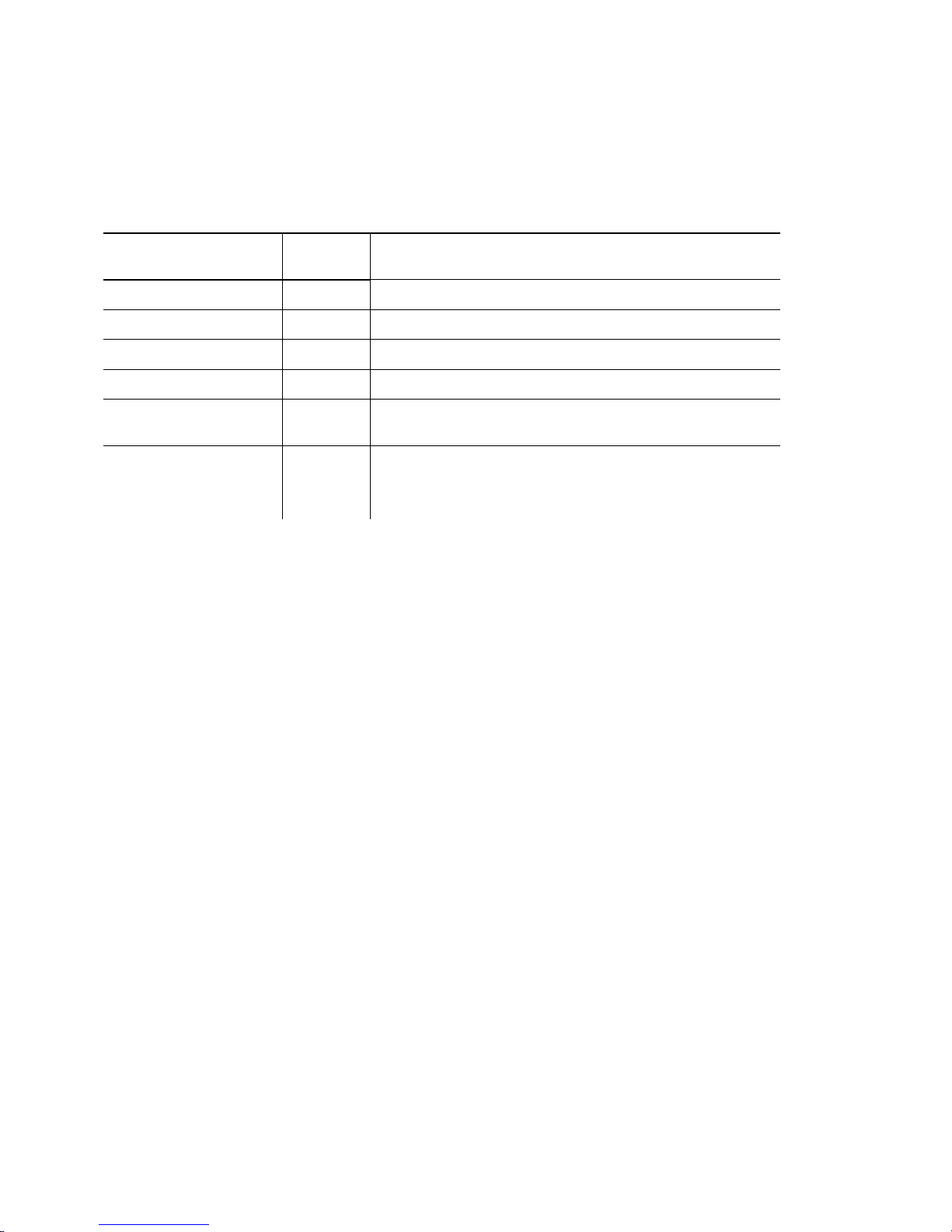
MPCLII Punctuation
Use the following symbols when creating MPCLII packets:
Character Decimal
Value Description
{ (left bracket)
} (right bracket)
p (vertical bar)
, (comma)
"ABC"
(quotation marks)
‘comment‘
(single quotation
marks)
123 start of header
125 end of header
124 field separator*
044 parameter separator
034 Quotation marks enclose character strings. Empty
quotes ("") identify null strings or unused fields.
039 Grave accents enclose comments. Any data
enclosed in grave accents is ignored. Do not embed
comments within a quoted string. Grave accents are
also used to reject mainframe data.
These MPCL characters are the default.
* The field separator is the split vertical bar, which we are representing as
manual. The decimal value is 124. To enter this character, use the Shift key plus the
Split Vertical Bar key on your computer’s keyboard. Depending on your text editor, it
may appear as a solid vertical bar or as a split vertical bar.
p
in this
Standard Syntax Guidelines
When creating MPCLII packets:
N
Begin each packet with a
N
End each packet with an
N
Define no more than
one field. However, options are not counted as fields. The
actual number of fields a format can have may be less,
because the number of fields is limited by the available
memory.
N
The field number 0 to
starting at 1, instead of 0.
N
Do not use a field number more than once per format.
start of header ({
end of header (}
1000
fields in a format. Each
999
must be unique. We recommend
).
).
p
indicates
Configuring the Printer
2-3
Page 26

N
Define all fields in the order you want to image/print them.
The printer does not print in field number order.
N
Separate all parameters with a
N
End each field with a
N
Enter all information in CAPITAL letters, except words or
Field Separator ( p
Parameter Separator (,
).
phrases within quotation marks.
N
Include all parameters for a field unless documented as
optional.
N
Define non-printable text fields before the field to which they
apply.
N
Define options immediately after the field to which they apply.
N
Multiple options can be used with most fields. Options can be
used in any combination except as noted with each definition.
Options are processed in the order they are received.
N
Keep in mind that proportionally spaced fonts need wider
fields than monospaced fonts. For variable field data, use a
letter "W" to determine the maximum field size.
N
Do not place a new line (return) or any other non-printing
character within a field definition. However, a carriage return
or line break after each
p
(field separator) makes your formats
easier to read.
T,1,20,V,30,30,1,1,1,1,B,C,0,0,0 p
T,2,10,V,50,30,1,1,1,1,B,C,0,0,0 p
).
N
Spaces are ignored, except within character strings.
N
Indenting options improves readability of your formats.
T,1,18,V,30,30,1,1,1,1,B,C,0,0,0 p
R,42,1 p
N
Use a tilde (~) followed by a 3-digit ASCII code in a quoted
string to send function codes or extended characters or send
the 8-bit ASCII code.
You can modify formats and fields with the optional entry method.
See "Optional Entry Method" in Chapter 6 for more information.
2-4
Configuring the Printer
Page 27

Using Online Configuration Packets
Use online configuration packets to change the printer settings.
You can send an individual packet or a packet that contains all
eight online configuration packets. You can supply all parameters
for each packet. Leave the parameters blank that you do not
need to change.
For example,
{ I,A,,,,1 p }
prints a slashed zero and uses the last sent online System Setup
parameters.
Make a copy of the online configuration worksheet in Appendix D,
"Format Design Tools," and save the original. Packets A-M are
listed on the worksheet.
When you turn off the printer, all the information in the online
configuration packets is saved and used when the printer is
turned back on. After you change printer configurations, you
must resend the format, batch, or graphic to the printer before the
changes take effect.
Configuration Packet Header
Always include an I
before the packet identifier (A, B, C, etc.). The I
identifies the data stream as a configuration packet.
Note:
Include the I parameter with each packet if you are
sending them individually. Include it only at the
beginning of a data stream if you are sending multiple
packets.
, immediately after the left bracket { and
parameter
Configuring the Printer
2-5
Page 28

This is the syntax to use when you create online configuration
packets:
Syntax
{
I
,
1 to 8 optional packets
A, parameter 1...parameter 5 p
B, parameter 1...parameter 5 p
C, parameter 1...parameter 5 p
D, parameter 1...parameter 3 p
E, parameter 1...parameter 9 p
F, parameter 1...parameter 5 p
G, parameter 1...parameter 4 p
M, parameter 1...parameter 4 p
}
Start of Header
Configuration Header
System Setup
Supply Setup
Print Control
Monetary Formatting
Control Characters
Communication Settings
Backfeed Control
Memory Configuration
End of Header
Syntax for single packet
{
I
,
A, parameter 1...parameter 5
}
Start of Header
Configuration Packet Identifier
System Setup
End of Header
You can also add a configuration to RAM or specify units for
supply, print, margin, and cut positions. If you use the optional
parameters with the
packet, any online configuration packets
I
following the split vertical bar ( p ) must specify distances using
the selected units. However, the test labels display the units in
dots, even if you entered them in English or Metrics units.
Syntax
1. header Constant I.
2. ID# ID. Use
3. action Action. Options:
4. device Storage Device. Use R (Volatile RAM)
2-6
Configuring the Printer
{header,ID#,action,device p }
0.
A
U
Add configuration.
Upload User Configuration.
Page 29

5. units Units. (Optional parameter.) Options:
E
M
G
English
Metric
Dots
Example
{I,0,A,R,E p
C,0,25,0,0,0 p }
Adds a configuration to volatile RAM and specifies English units.
It also uses the default contrast, moves print 0.25 inches closer to
the bottom of the supply and does not change the margin
adjustment, prints at the default print speed, and uses the default
printhead width.
If you do not use the optional parameters, the syntax for the
online configuration packets does not change. For example,
p
{I,C,0,50,0,0,0
}
uses the default contrast, moves print 50 dots (0.25) inches
closer to the bottom of the supply and does not change the
margin adjustment, prints at the default print speed, and uses the
default printhead width.
Example
{I,0,U,R p }
Uploads the printer configuration from volatile RAM and returns
the following to the host.
A,0,0,0,0,0 p
B,1,1,0,0,0 p
C,0,0,0,0,0,0 p
D,1,0,2 p
E,"~123~044~034~124~125~126","","~013~010" p
F,3,1,0,0,1 p
G,0,65,65 p
M,R,76365,45190,N,0,0 p
M,R,R,640 p
M,T,R,640 p
M,I,R,3300 p
M,D,R,640 p
M,F,R,1280 p
M,V,R,3840 p
Configuring the Printer
2-7
Page 30

The parameters for each packet (A-M) are displayed. In the first
line that begins with M, 76365 is the total volatile memory
available, 45190 is the memory available in volatile RAM. There
is no non-volatile RAM available. The remaining lines beginning
with M list the buffer sizes in 1/10K for the Receive, Transmit,
Image, Downloadable Fonts, Formats, and Scalable Fonts
Buffers.
Configuration Syntax Guidelines
When creating a printer configuration packet:
N
Follow the "Standard Syntax Guidelines" listed at the
beginning of this chapter.
N
Begin a packet with the configuration header (I).
N
Download multiple configuration packets within one packet or
download a single configuration packet.
N
If you change any of the online configuration packets, resend
the format packet to the printer, so the configuration changes
take effect.
N
Make sure the communication settings at the host match those
at the printer.
N
Send configuration packets once per session (each time the
printer is turned off and then back on), not with every format
or batch packet.
Making Print Adjustments
You can adjust where the printer prints on your supply by
adjusting the supply, print, or margin positions. However, keep in
mind the following:
N
Supply adjustments across the width of your supply, such as
the margin position, are based in dots- either 203 dpi or 300
dpi, depending on your printhead density.
N
Supply adjustments for the length of your supply, such as
supply position or print adjustment, are always measured in
1/203 of an inch, regardless of your printhead density.
2-8
Configuring the Printer
Page 31

Defining the System Setup Packet
Use the system setup packet (A) to select the power up mode,
display language, print separators between batches, print a
"slashed zero," and select the symbol set.
Syntax
{I,A,powup_mode,language,sep_on,slash_zero,
symbol_set p}
A1. A System Setup Packet
A2. powup_mode Online Mode. Options:
0
1
A3. language Display Language. Options
0
1
2
3
4
5
6
7
8
9
10
11
12
A4. sep_on Batch Separators. Options:
0
1
2
online mode (default)
offline mode (9855/9860)
English (default)
French
German
Spanish ES
Japanese
Portuguese
Italian
Swedish
Spanish2 - MX
Danish
Dutch
Finnish
Norwegian
Does not print a separator (default)
Prints a separator
Double-length separator- prints 2 tags (9855/9860)
Note:
A5. slash_zero Slash Zero. Options:
0
1
Do not use batch separators with continuous
(non-indexed) supply or RFID supply. If using a
stacker, the batch separator is 3.66 inches long.
Print a standard zero (default)
Print a zero with a slash through it
Configuring the Printer
2-9
Page 32

A6. symbol_set Symbol Set. Options:
0 Internal (default)
1 ANSI
2 Code Page 437 (Latin U.S.)
3 Code Page 850 (Latin 1)
4 Code Page 1250 (Latin 2)
5 Code Page 1251 (Cyrillic)
6 Code Page 1252 (Latin 1)
7 Code Page 1253 (Greek)
8 Code Page 1254 (Turkish)
9 Code Page 1255 (Hebrew)
10 Code Page 1256 (Arabic)
11 Code Page 1257 (Baltic)
12 Code Page 1258 (Vietnamese)
13 DOS Code Page 852 (Latin 2)
14 DOS Code Page 855 (Russian)
15 DOS Code Page 857 (IBM Turkish)
16 DOS Code Page 860 (MS-DOS Portuguese)
17 Wingdings
18 Macintosh
19 UNICODE
20 BIG5
21 GB2312
22 SJIS (Shift JIS) to SJIS (Code Page 932, Japanese)
23 GB2312 to GB2312 (Code Page 936, Simplified Chinese)
24 BIG5 to BIG5 (Code Page 950, Traditional Chinese)
Note: The CG Triumvirate typefaces support only the
ANSI and DOS Code Page 437 and 850 Symbol Sets.
The scalable font does not support Code Page 1256
(Arabic). Code pages 852-860 and 1250-1258 may
only be used with downloaded TrueType® fonts or the
scalable font. Code pages 19-24 require the memory
expansion option and a downloaded double-byte
TrueType font. TrueType fonts are designed to be
regionally specific; therefore, all code pages may not
be supported in a given font. See Appendix C for
more information.
Example
{I,A,0,0,1,1,0 p }
Powers up the printer in the online mode, displays prompts in
English, prints a separator after each batch, prints zeros with
slashes through them, and uses the internal symbol set.
2-10 Configuring the Printer
Page 33

Defining the Supply Setup Packet
Use the supply setup packet (B) to select supply type, ribbon,
feed mode, supply position, and cut position.
Syntax
{I,B,supply_type,ribbon_on,feed_mode,
supply_posn,cut_posn,skip_index p}
B1. B Supply Setup Packet
B2. supply_type Supply Type. Options:
0
1
2
3
Note:
B3. ribbon_on Ribbon. Options:
0
1
2
You must use a print speed of 2.5 IPS with the high energy
ribbon. Serial bar codes cannot be printed using the high
energy ribbon. Settings for ribbon and supply type must
match the supplies loaded in the printer; otherwise, an error
occurs. To clear the error, turn off the printer and change the
configuration packet. Turn on the printer and resend the
packet.
Black mark supply
Die Cut/edge aperture supply (default)
Continuous (non-indexed) supply
Center Aperture supply (9855/9860)
You must use continuous supply in continuous mode.
Do not use continuous supply with extended
backfeed or 94x5 emulation. If your aperture supply
has holes on the edge, use 1. If your aperture supply
has holes in the center, use 3.
Ribbon not installed
Ribbon installed (default)
High Energy Ribbon installed (9855/9860)
B4. feed_mode Feed Mode. Options:
0
1
Continuous operation (default)
On-demand mode
Configuring the Printer
2-11
Page 34

B5. supply_posn Supply Position. Range:
default. Adjusts the machine to print at the vertical 0,0 point
on the supply. This adjustment accounts for mechanical
tolerances from machine to machine. The supply position
adjustment only needs to be made on the initial machine
setup. Adjust the supply position if formats do not start at the
0,0 point on the supply. Increase the supply position to move
print up, decrease to move print down on the label. To verify
the 0,0 point, print a test label. See "Printing a Test Label" in
Chapter 8 for more information.
For the RFID printer, adjust the supply position according to
the RFID Setup Guide and Supply Chart.
You can not change the supply position while the printer is
active. Changing the supply position will affect the print
position, dispense position, and backfeed distance. Once the
supply position is set, use the print control packet and
backfeed control packet to adjust printing and the dispense
position.
-300 to 300
in 1/203 inch. 0 is the
B6. cut_posn Cut position. Range:
9825. Adjusts where the tag is cut. The printer adjusts the
cut position according to the black marks on the supply. You
may need to adjust for aperture supplies. Increase to move
the cut up, decrease to move the cut down.
B7. skip_index Skip index mode. The 9825 printer does not support skip
index mode. If using RFID supplies, do not use skip index
mode. Options:
Example
0
1
{I,B,0,0,1,10,50,1 p }
Disable skip index mode (default)
Enable skip mode. Allows the printer to skip a
sense mark and print an image over multiple labels.
-300
to
300
in 1/203 inch. Use 0 for the
Indicates black mark and thermal direct stock has been loaded,
causes the printer to operate in on-demand mode, feeds the
supply approximately .05 inches up before printing the format on
each label (10/203 inches), feeds the supply .25 inches (50/203
inches) before cutting, and enables skip index mode.
2-12
Configuring the Printer
Page 35

Defining the Print Control Packet
Use the print control packet (C) to set the contrast, print, and
margin adjustment, print speed, and printhead width.
Syntax
{I,C,contrast,print_adj,margin_adjust,
speed_adj,ph_width p }
C1. C Print Control Packet
C2. contrast Print Contrast. Range:
C3. print_adj Print adjustment (position). Range:
450
to
where data prints vertically on the supply. Increase the print
position to move print up, decrease to move print down.
For the RFID printer, adjust the print position according to the
RFID Setup Guide and Supply Chart.
C4. margin_adj Margin adjustment (position). Range:
(or 1/300 inch for 9855/9860). 0 is the default. Adjusts where
data prints horizontally on the supply. Increase the margin
position to move print to the right, decrease to move print to
the left. Margin and print position are format adjustments.
They will not affect the supply position, dispense position, or
backfeed distance.
C5. speed_adj Print speed in inches per second (ips). Options:
(9855/9860) in 1/203 inch. 0 is the default. Adjusts
0
25
40
60
80
100
120
Default (formats with serial bar codes automatically
print at 2.5 ips)
2.5 ips (default for serial bar codes)
4.0 ips
6.0 ips (default)
8.0 ips (9855/9860)
10.0 ips (9855 with 203 dpi)
12.0 ips (9855 with 203 dpi and high speed option)
-699
to
699
. 0 is the default.
-99
to 99 (9825) or
-99
to
99
-450
in 1/203 inch
Note:
C6. ph_width Width of the printhead in dots. Use 0.
Serial bar codes with an 8-dot narrow element do not
automatically print at 2.5 ips. Serial bar codes
printed at speeds greater than 2.5 ips may not scan
properly. However, the 985x and 9860 printers can
print 203 dpi serial bar codes with narrow elements of
3 dots (or greater) at 4.0 ips. You must use a print
speed of 2.5 ips with the high energy ribbon. See
"Special Printing Considerations," in Chapter 6 for
more information.
Configuring the Printer
2-13
Page 36

Example
{I,C,0,-20,-10,0,0 p }
Uses the default contrast, moves print 0.1 inch closer to the
bottom of the supply (20/203 inches) and .05 inch to the left on
the supply (10/203 inches), prints at six inches per second, and
uses the default printhead width.
Defining the Monetary Formatting Packet
The monetary formatting packet (D) selects the monetary symbols
to print for a price field. Use the monetary formatting packet to
select primary and secondary monetary symbols, and designate
the number of digits to appear at the right of a decimal.
Syntax
D1. D Monetary Formatting Packet
D2. cur_sym Currency Symbol. Options:
{I,D,cur_sym,secondary,decimals p }
0
1
2
3
4
5
6
7
8
9
10
11
12
13
14
15
16
Note:
No symbol
USA ($, Dollar- default)
UK (£, Pound)
Japan (¥, Yen)
Germany (1, Deutsche Mark)
France (F, Franc)
Spain (P, Peseta)
Italy (L., Lira)
Sweden (Kr, Krona)
Finland (2, Markka)
Austria (6, Shilling)
India (Rs, Rupee)
Russian (3, Ruble)
Korean (4, Won)
Thai (5, Baht)
Chinese (¥, Yuan)
Euro-Dollar (c)
To use these symbols, select the internal symbol set.
2-14
Configuring the Printer
Page 37

D3. secondary Secondary Sign. Secondary symbols only print if you
designate at least one decimal place. Options:
0
1
D4. decimals Number of digits to the right of the decimal. Options:
0
1
2
3
No secondary sign (default)
Print secondary sign
No digits
One digit
Two digits (default)
Three digits
Example
{I,D,1,1,2 p }
Prints the dollar sign, uses a secondary symbol, and places two
digits to the right of the decimal.
Defining the Control Characters Packet
Use the control characters packet (E) to change the MPCLII
control characters, enable and disable the immediate commands,
and change the default terminator character for job requests and
ENQ’s.
Changes take effect with the first character following the end of
header character } of the configuration packet. Each control
character must be unique and cannot appear anywhere else in
your packet, except within quotation marks. You can customize
the trailer characters to work with your host.
Note:
Wait two seconds for the new characters to take effect
before sending packets using the new characters.
Use the following syntax for the control characters packet. Notice
all but the first parameter are within quotation marks.
Configuring the Printer
2-15
Page 38

Syntax
E1. E Control Characters Packet
{I,E,"ANSI_cd","string1","string2" p }
E2. "ANSI_cd"
E3. "string 1" Terminator for status requests and ENQ requests. Up to any 3
E4. "string 2" Terminator for job requests and data uploads. Up to any 3
~123
~044
~034
~124
~125
~126
def. ch.
Note:
characters in the 0 to 255 decimal range. The default is
"013". Sending "" disables this sequence.
characters in the 0 to 255 decimal range. The default is none.
Sending "" disables this sequence.
Start of header { (left bracket)
Parameter , (comma)
separator
Quoted strings " (quotes)
Field separator
End of header } (right bracket)
Data escape ~~ (double tilde)
character (optional)
Immediate command character (optional).
Up to any 3 characters in the 0 to 255 decimal
range. The character must be defined before this
command can be used. The caret (~094) is
normally used.
"ANSI_cd" includes seven separate parameters. The
first five parameters are required. The other
parameters are optional.
p
(pipe sign- use hex 7C)
2-16
After you change these parameters, all packets, including any
future configuration packets, must use the new control characters.
We recommend using the tilde and ASCII character code
sequence when sending this packet multiple times. Also, set the
packet delimiters to characters within the 21 hex to 7E hex range.
You must send the control characters packet to enable the
immediate commands. An immediate command executes
immediately, even if it is embedded within quotation marks, and
all data following the command in the string is ignored.
Configuring the Printer
Page 39

Example
{I,E,"~123~063~034~124~125~126~094" p }
Changes the parameter separator character from , to ?. The
other control characters remain unchanged. It also enables the
immediate commands by defining the ^ symbol as the command
identifier.
Resetting Control Characters
You can change the characters in the previous example back to
their original settings by downloading this packet:
{I?E?"~123~044~034~124~125~126~094"
Notice that the parameter separator is ? in this packet. This is
the parameter separator that was set before this packet. Once
the packet is received by the printer, the new parameter separator
(a comma, in this case) is valid.
Be careful when using this feature. If you forget what the control
characters were changed to, print a test label. (The test label
lists the current control characters.) See "Printing a Test Label,"
in Chapter 8 for more information.
p
}
Using Immediate Commands
Immediate commands affect printer operation as soon as the
printer receives them, even if they are included within a packet or
used inside quotation marks.
You can use immediate commands to change immediate
command or status polling control characters, reset the printer, or
cancel and repeat batches.
Configuring the Printer
2-17
Page 40

Enabling Immediate Commands
When the printer is first turned on, these commands are not
available. To use these commands, you must first send the
control characters packet and define the immediate command
control character. The immediate command control character is
saved in non-volatile RAM and therefore not lost after you turn off
the printer. Once the immediate command control character is
defined, the immediate commands are enabled.
Sending Immediate Commands
Immediate commands consist of a three- or four-character
sequence you can send in a packet or embed in your application.
Each command must be sent separately.
Syntax
control character_immediate command
The printer can accept only one immediate command at a time.
Sending a command before the previous one is completed can
result in an error.
Example
^CA
Immediately cancels all the batches in the queue. This example
assumes that the defined immediate command control character
is the caret (^).
2-18
Configuring the Printer
Page 41
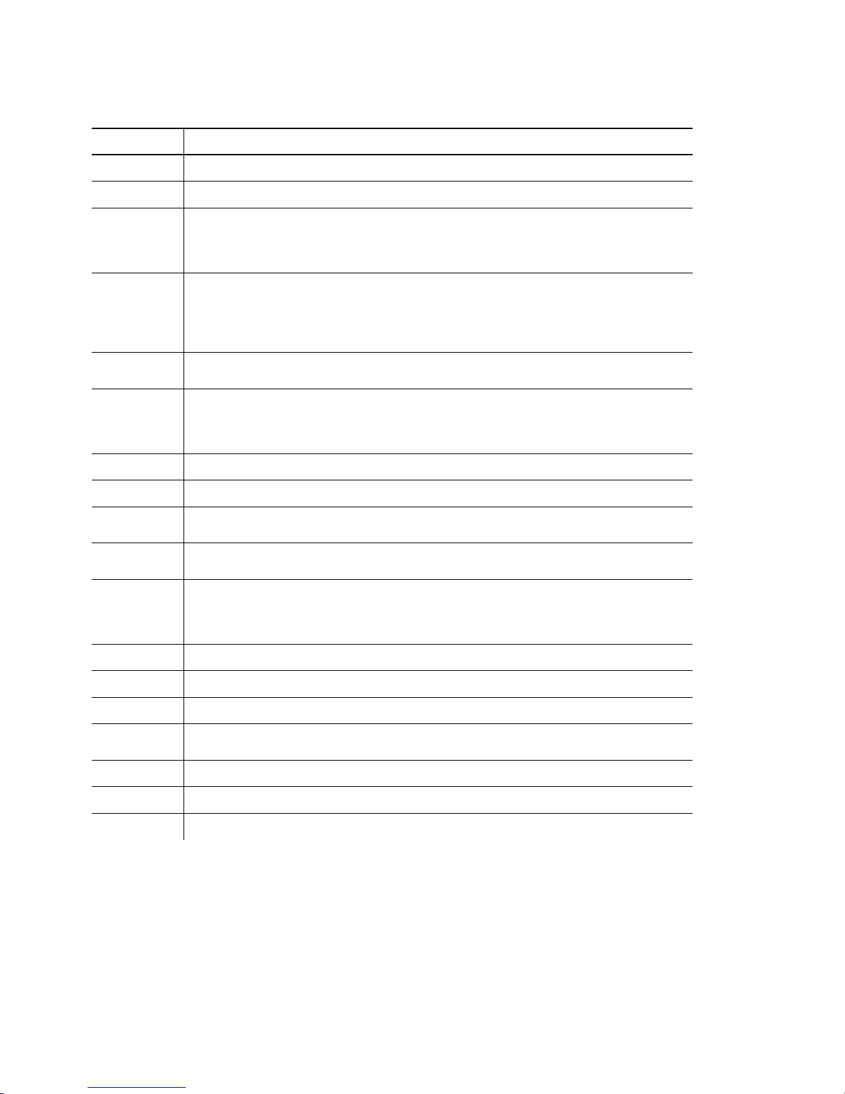
Command Parameter
^CA
^CB
^DD or
^DCd
^EA
^ER
^FD
^FF1
^FF2
^GD
^GE
^ID or ^ICd
^MC
Cancels all the batches in the queue.
Cancels the next batch in the queue.
Disables the MPCL data escape character (the tilde) and inhibits MPCL
from acting on ANY data escape sequence from the host. Sets the MPCL
data escape character to the ASCII value given by the d parameter. The
value can be any ASCII character.
Aborts an error condition. This command is the same as pressing
ESCAPE/CLEAR
Use ^RB to reprint batch.
CAUTION:
Resets the error. This command is the same as pressing
acknowledge an error. Normal operation will resume.
Feeds a label when printer is
FEED/CUT
mode.
Note:
Printer ignores this command if printing.
Formats flash memory
Returns the amount (in bytes) of the available flash memory.
Disables conversion of formats designed in 203 dpi density dot units to 300
dpi density.
Enables the conversion of formats designed in 203 dpi dot units (not
English or Metric) to 300 dpi.
Disables the Immediate Command feature by turning off the Immediate
Command escape character. Sets the Immediate Command escape
character to the ASCII value given by the d parameter. The value can be
any ASCII character.
Returns the customer ID or RPQ version to the host. (
to clear an error. May need to be sent multiple times.
Command causes the current batch to stop and the
condition that caused the error to remain uncorrected.
FEED/CUT
idle
. Simulates the operation of pressing
and dispenses the next label if printer is in the on-demand
00
to 99)
to
^MD
^MI
^MM
^MP
^MR
^MV
Returns the printhead dot density to the host. 00 = 203 dpi 01 = 300 dpi
Returns the customer ID or RPQ revision level to the host. (
Returns the model number to the host. 17 = 9825 18 = 9855
19 = 9860
Returns the prototype number to the host. (
Returns the revision number to the host. (00 to 99)
Returns the version number to the host. (00 to 99)
00
to 99)
00
to 99)
Configuring the Printer
2-19
Page 42

Command Parameter
^PR
^RB
^RS
^SD or
^SCd
^SFa
^SFb
^SFc
^SFd
^SFe
^SFf
^SFg
Resets the printer. This command takes five seconds to complete and then
the printer is ready to receive data. It has the same effect as turning off
and then turning on the printer.
Note:
Repeats the last printed batch, printing the same number of labels as
specified in the original batch. This command does not work if using batch
separators.
Note:
Resynchronizes supply when supply roll is changed.
Note:
Disables the status polling feature by turning off the status polling control
character. Sets the status polling control character to the ASCII value
given by the d parameter. The value of d can be any ASCII character.
Loads script with host response.
Loads script without host response.
Enables script.
Disables script.
Uploads script version information.
Deletes script.
Turns on ENQ status polling before it reaches the script.
Command should be used only when the printer is
Printer ignores this command if printing.
Printer ignores this command if printing.
not
printing.
^SFh
^SFi
^SFj
^TP
Turns off ENQ status polling before it reaches the script.
Turns on immediate commands before it reaches the script.
Turns off immediate commands before it reaches the script.
Prints a test label set.
Note:
Printer ignores this command if printing.
The table represents the defined immediate command control
character as ^ and the defined status polling control character as
d
. You may define these characters to suit your needs.
Note:
To use the immediate command control character or the
status polling character within your data, use the tilde
sequence.
2-20
Configuring the Printer
Page 43

Defining the Communication Settings Packet
Use the communication settings packet (F) to set the baud rate,
word length, stop bits, parity, and flow control for serial
communications. To set parallel communications, see "Using
Parallel Communications."
Changing the communication settings takes approximately two
seconds. Communications sent during this interval will be lost.
Make sure the host communication values match the values on
the printer and the host is capable of communicating at the speed
you select for the printer.
Do not add any characters, such as a carriage return/line feed, in
your communication settings packet or communications errors
may occur.
Syntax
{I,F,baud,word_length,stop_bits,parity,
flow_control p }
F1. F Communication Settings Packet
F2. baud Baud Rate. Only the 9855 and 9860 printers support baud
rates greater than 38400. Options:
0
1200
2
4800
4
19200
6
57600
F3. word_length Word Length. Options:
0
1
F4. stop_bits Stop Bits. Options:
0
1
F5. parity Parity. Options:
0
1
2
7-bit word length
8-bit word length (default)
1-stop bit (default)
2-stop bits
None (default)
ODD parity
EVEN parity
1
2400
3
9600 (default)
5
38400
7
115200
Configuring the Printer
2-21
Page 44

F6. flow_control Flow Control. Options:
0
1
None
DTR (default)
2
3
(CTS)
XON/XOFF
Example
Note:
{I,F,3,1,0,0,1 p }
If you use the DOS COPY command to download
your formats, set "Flow Control" to
XON/XOFF).
DTR
(not
Uses 9600 baud, an 8-bit word length, one stop bit, no parity, and
the DTR mode.
Defining the Backfeed Control Packet
Use the backfeed control packet (G) to enable or disable the
backfeed option, set the dispense position and the backfeed
distance. Backfeed works by advancing each printed label to the
desired dispense position. Once that label is removed, the next
label to be printed is backed up underneath the printhead. In
continuous mode, only the last label in the batch is advanced to
the dispense position. You may need to adjust the dispense
position to allow labels to be removed, die cut labels to be
removed easily, or to prevent them from falling off.
2-22
Extended backfeed is available on the 9855 printer with a knife
installed. Extended backfeed feeds a tag far enough out to be cut
and backfeeds the next tag to the printhead line. You can not
change the backfeed distance while the printer is active.
Extended backfeed eliminates printed tags being left between the
printhead and knife. Extended backfeed
non-indexed (continuous) supply/mode.
backfeed when sensing on attacher-hole supplies.
The 9860 printer automatically backfeeds when necessary.
Backfeed is also cut-mode dependent. See "Defining the Batch
Control Field" in Chapter 6 for more information about the best
cut mode for your application.
Configuring the Printer
does not
work with
Do not use extended
Page 45

Do not use backfeed (normal or extended) with supplies less than
0.75 inches. We recommend using 0.5-inch gap supplies in peel
mode when backfeed is disabled.
The dispense position and backfeed distance are optional
parameters and do not have to be specified. However, they allow
for greater precision when positioning the supply.
Syntax
G1. G Backfeed Control Packet
G2. action Action. If using one-inch RFID Supplies, do not use backfeed.
G3. dis_pos Dispense Position. Adjusts the stopping point of the label.
G4. bkfd_dis Backfeed Distance. Amount to move label backwards. 10 to
{I,G,action,dis_pos,bkfd_dis p }
Options:
0
1
2
200
to
applicator.
200
dots (default 65 dots). Use 95 dots for the printer
applicator. This distance can not be greater than the dispense
position.
The backfeed distance should equal the dispense position.
An exception is if you are tearing instead of peeling. Then,
the backfeed distance must be 30 dots (.150 inches) less than
the dispense position. However, you will have a 30 dot
non-print zone on your supply. The 30-dot difference
accounts for improper tearing of butt cut supplies, because
you do not want any exposed adhesive under the printhead.
disable backfeed (default)
enable backfeed (use on any printer without a knife)
enable extended backfeed (use on any printer with
a knife)
50
dots (default 65 dots). Use 95 dots for the printer
Example
{I,G,2 p }
Enables extended backfeed and cuts any tags remaining between
the knife and printhead and moves the supply backwards so the
next tag is underneath the printhead. Using cut mode 4, you do
not have to press
FEED/CUT
to cut the last tag.
Configuring the Printer
2-23
Page 46
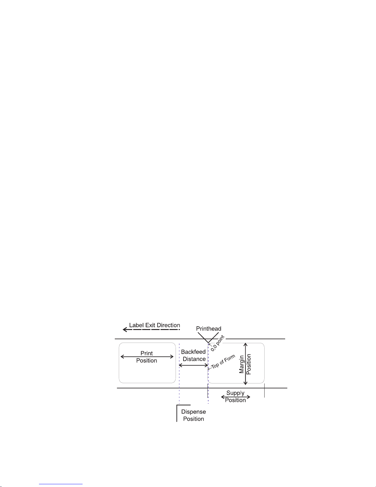
Example
{I,G,1,50,10 p }
Enables backfeed and sets the dispense position to 0.25 inches
(50/203) and the backfeed distance to 0.05 inches (10/203).
Special Considerations When Using Backfeed
Make a note of the following items:
N
Be careful when tearing supplies, because the adhesive can
adhere to the printhead or platen roller.
N
Backfeed affects each label in the on-demand mode or the
first and last label of the batch in continuous mode.
N
When backfeed is enabled and multiple batches are sent, the
printer may not backfeed between each batch.
N
Backfeed should only be used when you need to advance
labels to the desired dispense point.
N
Backfeed does not interfere with the supply, print, or margin
positions you have set.
N
If the supply inter-label gap is not between .07 inch to .15 inch
(14 to 30 dots), you must adjust the dispense position and
backfeed distance accordingly.
See the following graphic for a representation of the following
adjustments: dispense position, backfeed distance, supply
position, print position, and margin position.
2-24
Configuring the Printer
Page 47
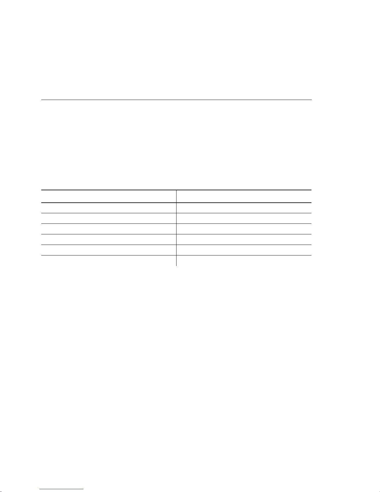
Contact Technical Support if you have problems adjusting where
the format prints on the supply.
Defining the Memory Configuration Packet
Use the memory configuration packet (M) to customize the size of
your printer’s buffers, which gives you greater flexibility in your
formats.
Memory must be allocated in 1/2K increments. The memory
configuration packet does not accept decimals, so enter whole
numbers. Multiply the amount to reallocate (in K) by 10. For
example,
To reallocate (in K) Enter this amount
110
1.5 15
220
2.5 25
153 1530
229.5 2295
Each buffer’s allocated memory remains in effect until that buffer
is reallocated. For this reason, you may want to reallocate all the
buffers when reallocating any buffer. If you reallocate more
memory than you have available, you will receive an error.
Syntax
M1. M Memory Configuration Packet
M2. buffer Buffer type:
{I,M,buffer,device,buffer_size p }
D
F
I
R
T
V
Downloadable Fonts
Format
Image
Receive
Tr an s mi t
Scalable (vector) Fonts
Configuring the Printer
2-25
Page 48
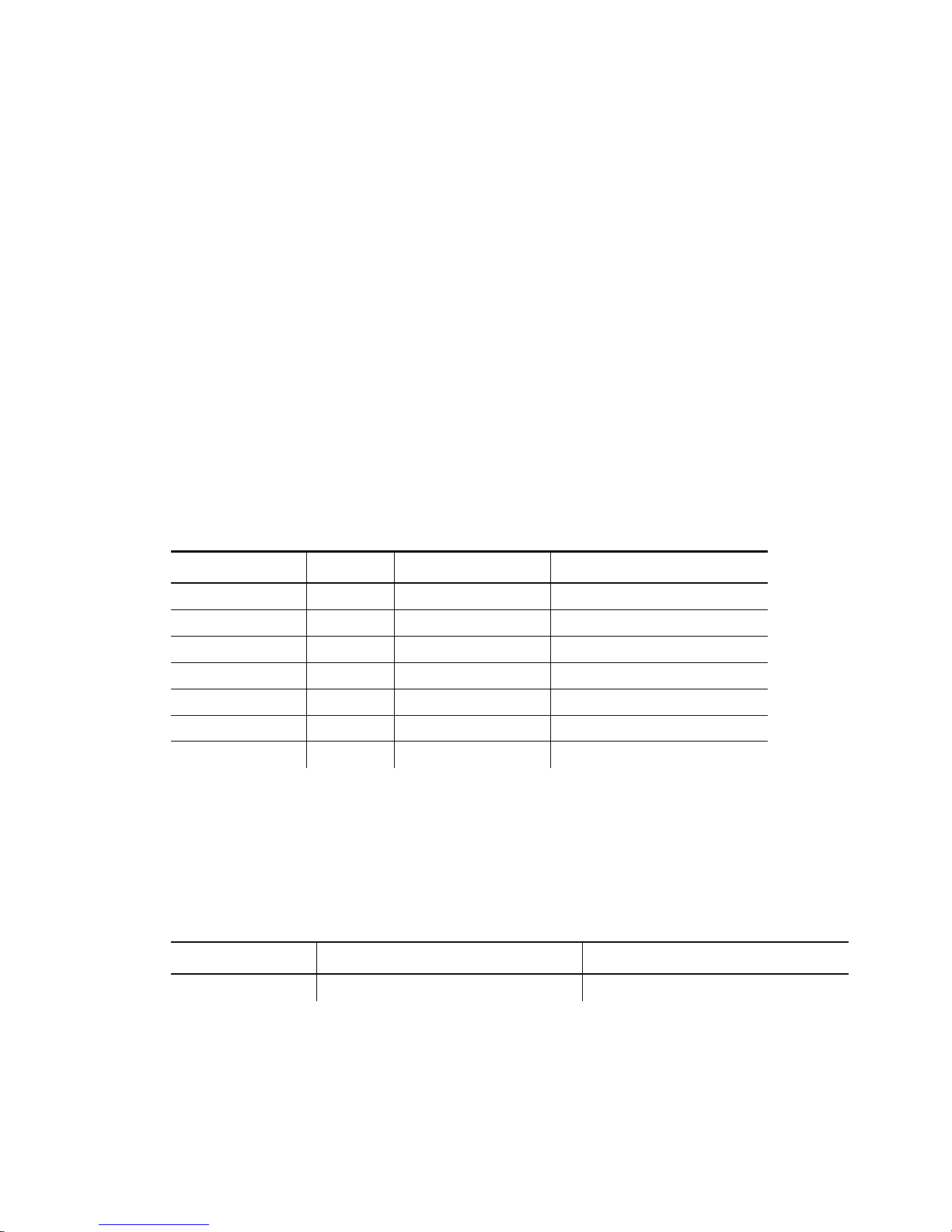
M3. device Storage type:
F
R
Note:
M4. buffer size Buffer size in 1/10K ranges. See the following table for
ranges.
Example
{I,M,I,R,1530 p }
Flash Memory
Volatile RAM
You cannot reallocate flash memory.
Stores the image buffer in volatile RAM and allocates 153K for it.
The following table lists the configured buffer sizes and min-max
values for your printer. The printer’s configuration is stored in
non-volatile RAM and retained when you turn off the printer. The
max. value for each buffer is listed; however, the sum of all the
buffers cannot exceed the max. available memory of the printer.
Buffer Type 9825* 9855/9860
Transmit Vol. 2K (.5K- 4K) 64K (.5K- 128K)
Receive Vol. 8K (2K- 64K) 64K (2K- 128K)
Image Vol. 330K (41.5K- 640K) 330K (41.5K- 6144K)
Downld. Fonts Vol. 64K (8K- 640K) 64K (8K- 8192K)
Scalable Fonts Vol. 64K (32K-640K) 384K (32K-8192K)
Formats Vol. 64K (16K- 640K) 128K (16K- 1024K)
Internal NA cannot reallocate cannot reallocate
* The 9825, 9855, and 9860 printers do not have non-volatile RAM; however, you can
store formats, fonts, and graphics in flash memory. Change the storage device of your
packets to "F" instead of "N."
Use the following table to see how much memory is available to
reallocate.
RAM* 9825 9855/9860
Volatile RAM 1 Meg 8 Meg
* You cannot reallocate more memory than what is available, or you will receive an error.
Memory expansion is an option available on the 9855 and 9860 printers.
2-26
Configuring the Printer
Page 49

Checking Current Buffer Sizes
Send a configuration upload packet to check the sizes of your
current buffers. See "Configuration Packet Header" for more
information. After you check your current buffer sizes you can
begin reallocating memory.
If you want to increase your image buffer and you will not be
using scalable fonts, add that memory into your image buffer.
Example
{I,M,R,R,20 p
M,T,R,10 p
M,D,R,80 p
M,V,R,160 p
M,I,R,3200 p }
Receive buffer 2K
Transmit buffer 1K
Downloadable fonts 8K
Scalable fonts buffer 16K
Image buffer 320K
Make sure memory is available before adding memory to a buffer.
In the above example, if the image buffer (M,I,R,3200) was
defined before the downloadable fonts and scalable fonts buffers
(M,D,R,80 and M,V,R,160) were defined, an error would have
occurred.
About Memory Buffers
Transmit Buffer Used to send ENQ, job, and upload
responses. This buffer must be allocated as
volatile (R) RAM.
Receive Buffer Used to save data received from the host
before it is processed by the printer.
Changing this buffer size affects the amount
of data the printer can receive without using
flow control. This buffer must be allocated as
volatile (R) RAM.
Configuring the Printer
2-27
Page 50

2-28 Configuring the Printer
Image Buffer
Used to image the current format. The printers
support two 4-inch by 8-inch buffers. You can
create an image up to 16 inches long without
reallocating memory. The Image Buffer is cleared
after a printer reset.
Use the formula below to calculate the
approximate image buffer size.
21K x Length (for 203 dpi) OR
46K x Length
(for 300 dpi)
Length is the length of your label in inches.
203 DPI Example
21K x 25 = 525
(Multiply by 10 and round up to the next whole
number if necessary)
525K x 10 = 5250
Enter 5250 for your Image buffer.
300 DPI Example
46K x 26.75 = 1230.5
(Multiply by 10 and round up to the next whole
number if necessary)
1230.5 x 10 = 12305
Enter 12305 for your Image buffer.
Format Buffer
Used to store formats, batch data, and graphics.
Use the following formula to calculate the required
format buffer size:
Linecount x 50/1024
Linecount is the number of lines in your format
packet including the format header and all the
options.
The result of the above calculation is in kilobytes.
Formats remain in memory when you turn off the
printer.
Page 51

Downloadable
Fonts Buffer
Used to store downloaded soft (bitmapped or
TrueType) fonts. To determine the size of
your downloadable fonts, send a font packet.
For TrueType fonts, the file size, in bytes, is
the minimum amount needed in this buffer.
See "Using the Font Packet" for more
information.
Scalable (Vector)
Fonts Buffer
Used to image the scalable or downloaded
(TrueType or bitmapped) font characters.
Increasing this buffer size allows more
characters to be saved in cache memory, so
the characters do not have to be re-built the
next time they are printed. Use 0 if you are
not using scalable/TrueType fonts. This buffer
must be allocated as volatile (R) RAM.
The printer does not print the fonts if there is
not enough memory in this buffer to image
them.
Configuring the Printer
2-29
Page 52
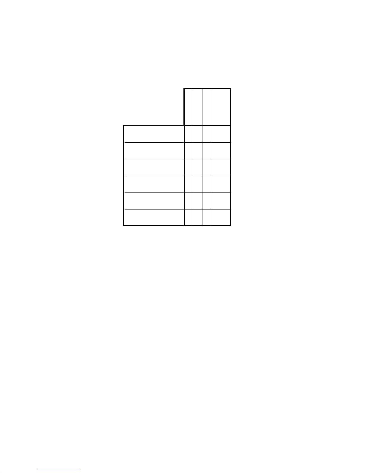
Buffer Worksheet
Make copies of this page to use as a buffer worksheet.
HEADER
DEVICE
BUFFER SIZE
maximum of 2295
DOWN LOADABLE
FONTS BUFFER
M
BUFFER
D
FORMAT
BUFFER
IMAGE
BUFFER
RECEIVE
BUFFER
TRANSMIT
BUFFER
SCALABLE
FONTS BUFFER
MF
MI
MR
MT
MV
R
R
R
maximum of 2295
maximum of 2295
maximum of 320
maximum of 40
maximum of 1280
Buffer Allocation Considerations
Keep these items in mind when allocating memory.
N
Do not allocate more memory than what is available.
N
Free memory from one buffer before you add it to another
buffer.
N
Reallocate all the buffers if you need to reallocate any buffer.
N
Send all buffer (re)allocations in one packet. The printer
evaluates each individual buffer allocation separately. If one
buffer allocation is invalid, the entire packet is invalid. If you
define a buffer size that exceeds the maximum value, an error
occurs. However, no information is lost.
2-30
Configuring the Printer
Page 53

N
Whenever the printer accepts a memory configuration packet,
it takes effect immediately, causing a printer reset. Any
information contained in the buffers is lost. Resend your
formats, batches, graphics, or fonts to the printer.
N
If you remap your image buffer, make sure the length and
width specified in your format header are not too large for the
current image buffer. In other words, if you remap for a 4 x 4
inch label, you cannot print a 4 x 6 inch label without receiving
an error, until you change your format header or increase your
image buffer.
Memory Considerations with Downloaded TrueType
Fonts
N
The size of the TrueType font file, in bytes, is the minimum
amount of memory you must have available in the
downloadable fonts buffer.
N
The scalable (vector) fonts buffer is used to image the
downloaded fonts (TrueType or bitmapped). If you are using
several downloaded TrueType fonts, you may need 100K or
more in this buffer. The printer does not print the fonts if there
is not enough memory in the scalable (vector) fonts buffer.
N
To use large point sizes (greater than 60 point), you must
reconfigure memory and increase the size of the scalable
(vector) fonts buffer.
N
Font storage is limited on the 9825 printer, because there is no
extended memory available.
Configuring the Printer
2-31
Page 54

Formatting Flash Memory
Before you send packets to flash memory, it must be formatted
first.
the Main Menu, select Setup, Flash Memory, then Format Flash.
The process takes a few minutes.
This is required once during initial printer setup.
From
Note:
When you format flash memory, all packets (formats,
fonts, graphics, etc.) stored in flash memory are deleted
and must be resent to the printer.
Flash Memory Guidelines
Use these basic guidelines for storing files in flash memory.
N
Your printer may have volatile RAM (packets deleted when the
printer is turned off), non-volatile RAM (packets saved when
the printer is turned off), and flash memory (packets saved
when the printer is turned off). Each printer has a different
limit of available memory.
N
Before you save any packets in flash memory, you must format
flash memory first. See "Formatting Flash Memory" for more
information.
N
Formats, graphics, and check digits can be saved in flash (but
they are also duplicated in RAM). Any packets saved in flash
cannot exceed the memory available in RAM.
N
Packets with the same number should not be added to flash
memory. If two packets with the same number are stored in
flash, only the last packet sent can be used. For example, if
you send the following packets to flash memory, only the
"Textiles" format can be used.
{F,10,A,F,E,300,200,"UPC"p}
{F,10,A,F,E,300,200,"Textiles"p}
N
Fonts are stored differently in flash. For example, the 9825
printer has very limited flash font memory and one TrueType
font may exceed that limit. For TrueType or double-byte fonts,
use a 9855 or 9860 printer with the memory expansion option.
2-32
Configuring the Printer
Page 55

N
There is not a 1-to-1 ratio between the memory in your printer
and the memory in your PC. For example, a file that is 5K in
Windows may require 15-20K to store in your printer.
N
When using graphics, use the lowest-resolution graphic
possible. If your printer uses a 203 dpi printhead, the
graphic’s resolution should be 150 to 200 dpi. In fact, 96 dpi
may work. Try to create the smallest file size possible.
N
Use temporary storage for graphics that are only used once or
twice. However, if you have a logo that is used on multiple
formats, save the graphic in flash. Once again, try to create
the smallest file size possible for your graphic.
N
Each line in a packet requires the same amount of memory.
The smaller the format, the less memory required to save it.
N
Flash memory cannot be reallocated.
Clearing Packets from Memory
You may want to remove packets from the printer to increase
memory storage capacity or if the formats/fonts/graphics are no
longer needed. In some cases, turning the printer off may clear
the packets from memory. If not, send a format clear packet.
Syntax
1. header Identifies the packet. Options:
2. packet# Identification number of the packet to clear (
3. action Action. Enter C to clear the packet.
4. device Storage device. Options:
Example
{header,packet#,action,device p }
A
F
G
W
number (
F
R
Check Digit Scheme
Format
Graphic
Font
0-9999
). 0 is for all formats, fonts, or graphics.
Flash
Volatile RAM
{F,1,C,R p }
Clears Format #1 from volatile RAM.
1-999
) or font
Configuring the Printer
2-33
Page 56

Using the Font Packet
You can use a font packet to add or clear downloaded fonts from
memory, upload your font buffer, or upload the cell size
information for a particular font. The font packet is useful when
you are downloading fonts. If you are using downloaded fonts,
the font number and the number of bytes each downloaded font
uses is listed.
This packet does not list the number of bytes the standard printer
fonts use.
Syntax
W1. W Writable Font Header.
W2. font# Font number from
W3. action Action. Options:
W4. device Device. Options:
{W,font#,action,device p }
0-9999
0 is for all fonts. 1 - 5 digits is the font number.
Example: 3 is the standard printer font, Bold.
A
C
H
M
Note:
F
R
Z
Adds the specified font.
Clears all or specified fonts, except ones in ROM.
Uploads font size information.
Uploads font memory usage information.
C does not clear (erase) fonts saved in the printer’s
flash memory. You must format flash memory to
erase fonts from the printer’s flash memory.
However, when you format flash memory, ALL fonts
saved in the printer’s flash memory are deleted.
Flash
Volatile RAM
All devices (use for upload).
.
If you are creating fonts, you need to have font data included with
this packet. Software is available to download from our Web site
to create the font data and packet.
2-34
Configuring the Printer
Page 57

Example
{W,0,M,R p }
Selects all fonts and checks the memory usage in RAM. The
printer returns the following to the host:
{W,0,M,R p
Number of bytes free, Number of bytes used p }
Example
Selects all fonts and uploads the font size information for any
downloaded fonts.
The 9855 printer returns the following to the host:
Font Style
Symbol Set
Ty p e
Cell Width
{W,0,H,Z p }
{W,0,H,Z p
Font Name
0,1,0,"Standard",0,0,0,14,22,14,22,3 p
0,1,1,"CGTriBd9",1,0,7,25,31,10,15,0 p
0,1,437,"CGTriBd9",1,0,7,25,31,10,15,0 p
0,1,850,"CGTriBd9",1,0,7,25,31,10,15,0 p
0,1,945,"X5 Standard",1,0,0,15,24,16,24,0 p
0,2,0,"Reduced",0,0,0,7,14,7,14,1 p
0,2,1,"CGTriumv6",1,0,5,17,21,5,10,0 p
0,2,437,"CGTriumv6",1,0,5,17,21,5,10,0 p
0,2,850,"CGTriumv6",1,0,5,17,21,5,10,0 p
0,2,945,"X5 Reduced",1,0,0,7,16,7,14,0 p
0,3,0,"Bold",0,0,0,24,34,24,34,3 p
Inter-Character Gap
0,3,945,"X5 Bold",1,0,0,30,48,26,36,0 p
0,4,0,"OCRA",0,0,0,13,24,13,24,3 p
0,5,945,"X5 OCRA",1,0,0,16,26,15,26,3 p
0,5,0,"HR1",0,0,0,12,20,12,20,2 p
0,6,945,"X5 HR1",1,0,0,12,20,15,26,2 p
0,6,0,"HR2",0,0,0,10,16,10,16,1 p
0,7,945,"X5 HR2",1,0,0,9,15,15,26,1 p
0,10,0,"CGTriBd9",1,0,7,25,31,10,15,0 p
0,10,1,"CGTriBd9",1,0,7,25,31,10,15,0 p
0,10,437,"CGTriBd9",1,0,7,25,31,10,15,0 p
0,10,850,"CGTriBd9",1,0,7,25,31,10,15,0 p
0,11,0,"CGTriumv6",1,0,5,17,21,5,10,0 p
0,11,1,"CGTriumv6",1,0,5,17,21,5,10,0 p
0,11,437,"CGTriumv6",1,0,5,17,21,5,10,0 p
0,11,850,"CGTriumv6",1,0,5,17,21,5,10,0 p
Spacing
Baseline
Cell Height
Nominal Width
Nominal Height
Printhead Density
Configuring the Printer
2-35
Page 58

0,15,0,"CGTriumv7",1,0,7,21,28,9,14,0 p
0,15,1,"CGTriumv7",1,0,7,21,28,9,14,0 p
0,15,437,"CGTriumv7",1,0,7,22,28,9,14,0 p
0,15,850,"CGTriumv7",1,0,7,22,28,9,14,0 p
0,16,0,"CGTriumv9",1,0,8,28,35,12,18,0 p
0,16,1,"CGTriumv9",1,0,8,28,35,12,18,0 p
0,16,437,"CGTriumv9",1,0,8,29,35,12,18,0 p
0,16,850,"CGTriumv9",1,0,8,29,35,12,18,0 p
0,17,0,"CGTriumv11",1,0,9,31,40,13,22,0 p
0,17,1,"CGTriumv11",1,0,9,31,40,13,22,0 p
0,17,437,"CGTriumv11",1,0,9,33,40,13,22,0 p
0,17,850,"CGTriumv11",1,0,9,33,40,13,22,0 p
0,18,0,"CGTriumv15",1,0,13,47,59,20,31,0 p
0,18,1,"CGTriumv15",1,0,13,47,59,20,31,0 p
0,18,437,"CGTriumv15",1,0,13,49,59,20,31,0 p
0,18,850,"CGTriumv15",1,0,13,49,59,20,31,0 p
0,510,0,"CGTriumv7",1,0,7,21,28,9,14,0 p
0,510,1,"CGTriumv7",1,0,7,21,28,9,14,0 p
0,510,437,"CGTriumv7",1,0,7,22,28,9,14,0 p
0,510,850,"CGTriumv7",1,0,7,22,28,9,14,0 p
0,511,0,"CGTriumv9",1,0,8,28,35,12,18,0 p
0,511,1,"CGTriumv9",1,0,8,28,35,12,18,0 p
0,511,437,"CGTriumv9",1,0,8,29,35,12,18,0 p
0,511,850,"CGTriumv9",1,0,8,29,35,12,18,0 p
0,512,0,"CGTriumv11",1,0,9,31,40,13,22,0 p
0,512,1,"CGTriumv11",1,0,9,31,40,13,22,0 p
0,512,437,"CGTriumv11",1,0,9,33,40,13,22,0 p
0,512,850,"CGTriumv11",1,0,9,33,40,13,22,0 p
0,513,0,"CGTriumv15",1,0,13,47,59,20,31,0 p
0,513,1,"CGTriumv15",1,0,13,47,59,20,31,0 p
0,513,437,"CGTriumv15",1,0,13,49,59,20,31,0 p
0,513,850,"CGTriumv15",1,0,13,49,59,20,31,0 p
0,70,0,"Paxar15",1,0,7,32,42,22,42,0 p
0,71,0,"Paxar18",1,0,9,34,51,27,51,0 p
0,72,0,"Nafta15",1,0,6,32,42,32,41,0 p
0,73,0,"Nafta18",1,0,8,48,51,46,50,0 p
0,21,0,"ZIAFont",0,0,0,5,9,5,9,1 p
0,22,0,"ZIBFont",0,0,0,7,11,7,11,2 p
0,23,0,"ZICFont",0,0,0,10,18,10,18,2 p
0,24,0,"ZIDFont",0,0,0,10,18,10,18,2 p
0,25,0,"ZIEFont",0,0,0,15,28,15,28,5 p
2-36
Configuring the Printer
Page 59

0,26,0,"ZIFFont",0,0,0,13,26,13,26,3 p
0,27,0,"ZIGFont",0,0,0,40,60,40,60,8 p
0,50,0,"EffSwissBold",1,1,92248 p
0,56,0,"PaxSymbols",1,1,12260 p }
* The CG Triumvirate typefaces are trademarks of Monotype Imaging, Inc.
Fonts 21-27 are only for the 9855 MLI printer.
Note:
Fonts
16, 17
Spacing
Ty p e
Baseline
Cell Width
Cell Height
Nominal Width
Nominal Height
Inter-Character
Gap
510, 511, 512
, and 18.
Monospaced (0) or proportional (1).
Bitmapped (0) or scalable (1).
Bottom of the font.
Horizontal number of dots to contain the
widest character.
Vertical number of dots to contain the tallest
character.
Average width for lower-case letters.
Average height for lower-case letters.
Default spacing between characters in
monospaced fonts.
, and
513
are the same as fonts 15,
Printhead Density
Displays whether a 203 (0) dpi or 300 (1) dpi
printhead is used.
The scalable font (font 50) does not display
which printhead (203 dpi or 300 dpi) is used.
Configuring the Printer
2-37
Page 60

Uploading Format Header Information
You can upload format header information from the formats in
memory to check the supply length and width for each format.
Formats stored in Flash memory are loaded into RAM when the
9855 or 9860 printer boots. However, the formats remain in Flash
memory when you turn off the printer.
Syntax
F1. header Format Header
F2. format# Format number from
F3. action Action. Options:
F4. device Device. Options:
Example
{header,format#,action,device p }
A
C
H
F
R
Z
{F,0,H,Z p }
Adds the specified format
Clears the specified format
Uploads format header information
Flash
Volatile RAM
All devices (use for upload)
0-999
. 0 is for all formats in memory.
Selects all formats in memory and returns the following:
{F,0,H,Z p
Fmt_1,406,406 p
Fmt_10,324,406 p
Fmt_15,812,812 p
Fmt_20,305,609 p
Fmt_25,1218,406 p }
Displays the format number, supply length and supply width (in
dots) for each format in memory.
Example
Selects format1 and returns the following to the host:
{F,1,H,Z p
Fmt_1,406,406 p }
Displays the supply length and supply width (in dots) for format1.
2-38
Configuring the Printer
{F,1,H,Z p }
Page 61

Defining a Verifier Configuration Packet
With the verifier configuration packet you can customize the
verifier for each format you print. You can select which bar codes
to scan, the acceptable ANSI grade levels, quiet zone,
X-dimension range, and more. You can download the Monarch®
Verifier Configuration Tool (from our Web site) to create this
packet or follow the syntax below.
Syntax
{V,format#,action,device,"name" p
D,"vfr_comds" p }
V1. V Verifier Configuration Packet.
V2. format# Number from
corresponds to this particular verifier configuration packet.
However, you can assign a verifier configuration packet to any
format even if the format number is not changed. See
"Defining Verifier Fields" in Chapter 3 for more information.
Note:
V3. action Action. Enter A to add a verifier configuration.
V4. device Storage device. Options:
F
T
0-999
You can specify up to 50 different verifier
configurations for your formats.
Flash. Stores the verifier configuration in the printer.
Packets stored in flash memory are saved when the
power is turned off.
Temporary. Passes the packet through the printer
and stores the packet in the verifier. Packets stored
in temporary memory are lost when the power is
turned off.
to identify the format number that
V5. "name" Packet name,
The name you enter here is shown as a custom configuration
on the menu for MODE. Refer to your verifier’s Operating
Instructions (available on our Web site) for more information.
D1. D Non-Printable Text/Data Field.
D2. "vfr_comds" Verifier commands. Must be enclosed within quotation marks.
Refer to the SV Series Operator’s Guide for the complete list
of verifier commands.
0-8
characters, enclose within quotation marks.
Configuring the Printer
2-39
Page 62

Example
{V,1,A,T,"BEAMON" p
D,"~LV02" p }
The verifier’s configuration packet ID is "1" and named
"BEAMON." The verifier packet is added to temporary memory. It
uses Mode 2.
Defining a Network Console Packet
The network console packet is only valid on a 9855 or 9860
Version 2.0 (or greater) printer containing MonarchNet2
software for the Monarch® 7410 or Monarch® 7411 Ethernet
Print Server. Use the network console packet to send console
commands directly to the network card via the printer’s serial port.
If the network card does not appear to be communicating with the
printer, you can use the network console packet to change the
SSID, IP Address, etc. of the network card.
Syntax
N1. N Network Console Packet.
N2. number Number from
N3. action Action. Enter A to add a verifier configuration.
N4. device Storage device. Enter T to pass the packet through the
N5. "name" Packet name, 0-8 characters, enclose within quotation marks.
C1. C Command field.
C2. "con_comds" Console commands. Must be enclosed within quotation
{N,number,action,device,"name" p
C,"con_comds" p }
0-999
printer and store the packet in the network card.
marks. Each command must be on a separate line. The
maximum number of characters per command is 100. Refer
to the list of console commands in the MonarchNet2
Operating Instructions (available on our Web site) for more
information.
Note:
The maximum number of commands per packet is
ten (10).
to identify the network console packet.
2-40
Configuring the Printer
Page 63

Example
{N,1,A,T,"mystore" p
C,"set ip me static
"
init" p
C,
"
exit" p }
C,
"
p
Sends the network conosle packet 1 "my store" directly to the
network card (T) and sets the IP method to static for determining
the IP Addresses. The Init and Exit commands must be used to
save changes and initialize the network card.
Configuring the Printer
2-41
Page 64

2-42
Configuring the Printer
Page 65

DEFINING FIELDS
This chapter provides a reference for defining
N
the format header
N
text, constant text, and non-printable text fields
N
bar code fields
N
line and box fields
N
verifier fields
N
RFID data fields.
3
Defining Fields
3-1
Page 66

Defining the Format Header
A Format Header begins a format file.
Syntax
{F,format#,action,device,measure,length,
width,"name" p
F1. F Format Header.
F2. format# Number from
1-999
F3. action Enter A to add a new format to the printer.
F4. device Format storage device. Options:
Flash (must be formatted first. See "Formatting Flash"
F
and "Flash Memory Guidelines" in Chapter 2 for more
information.)
Volatile RAM
R
F5. measure Unit of measure: E (English), M (Metric), or G (Graphic Dots).
See the following table.
Printer Unit of Measure Length Width
9825/
9855/
9860
9855/
9860
9855RFID
English (1/100 inch)
English (1/100 inch)
English (1/100 inch)
to identify the format.
Metric (1/10 mm)
203 dpi Dots
Metric (1/10 mm)
300 dpi Dots
Metric (1/10 mm)
203 Dots
300 Dots
75-1600
191-4064
152-3248
75-1200
191-3048
225-3600
75-1300
191-3302
152-2639
225-3900
32-400
81-1016
62-812
32-400
81-1016
96-1200
75-400
191-1016
152-812
225-1200
F6. length Length in selected units. Measure supply from the leading
F7. width Width, from left to right, in selected units. Use the previous
F8. "name" Format name (optional),
Example
Adds Format 1 ("TEXTILES") to the printer. It uses a three inch
long by two inch wide label.
3-2
Defining Fields
edge of one label to the leading edge of the next label. Use
the previous table for values.
table for values.
characters, enclose within
0-8
quotation marks. The range is
1-256
characters for the 9855
XML-enabled printer.
{F,1,A,R,E,300,200,"TEXTILES" p
Page 67
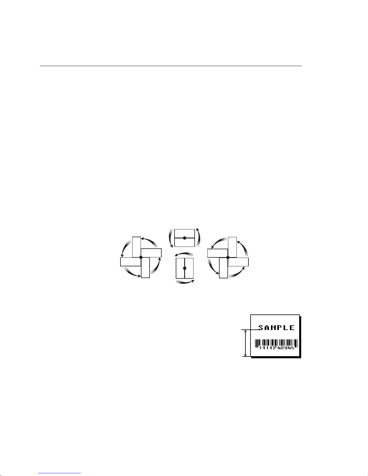
Defining Text Fields
Create a separate definition for each text field. If text falls on two
lines, each line of text requires a separate definition.
Syntax
T,field#,# of char,fix/var,row,column,
gap,font,hgt mag,wid mag,color,alignment,
char rot,field rot,sym set p
T1. T Text Field.
T2. field# Unique number from
1-999
T3. # of char Maximum number of printed characters is
T4. fix/var Fixed or variable length field. Options:
F
V
Fixed length
Variable length
T5. row For monospaced fonts, distance from bottom of print area to
the pivot point. The pivot point varies depending on how text
is justified.
1 (LEFT)
0 (TOP)
2 (BOTTOM)
3 (RIGHT)
to identify this field.
0-2710
0 (TOP)
2 (BOTTOM)
0 (TOP)
3 (RIGHT)
1 (LEFT)
3 (RIGHT)
1 (LEFT)
in the field.
2 (BOTTOM)
Left/Center/Right-Justified
Balanced
End-Justified
For proportionally spaced fonts, distance from bottom of print
area to baseline of characters in field.
Defining Fields
3-3
Page 68
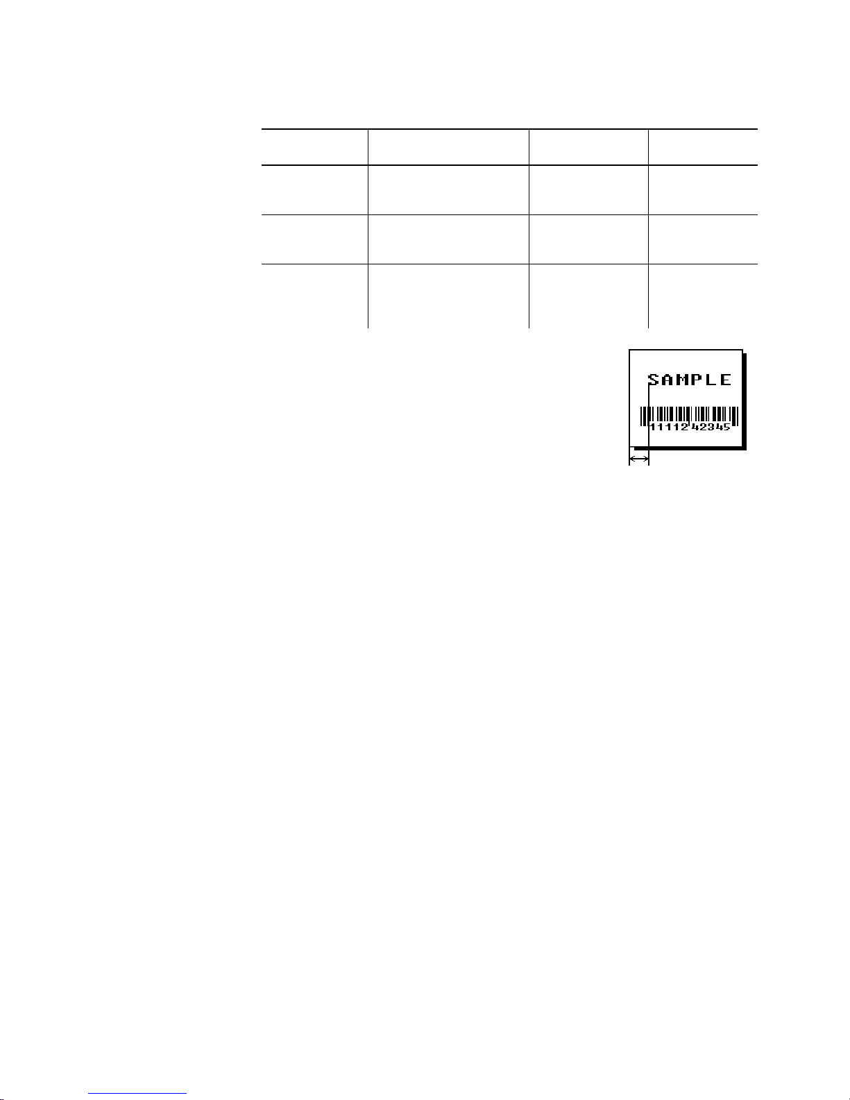
Printer Unit of Measure Row or
End Row
9825/
9855/
9860
9855/
9860
9855RFID
English (1/100 inch)
Metric (1/10 mm)
203 dpi Dots
English (1/100 inch)
Metric (1/10 mm)
300 dpi Dots
English (1/100 inch)
Metric (1/10 mm)
203 Dots
300 Dots
0-1599
0-4061
0-3246
0-1199
0-3045
0-3597
0-1299
0-3299
0-2637
0-3897
T6. column Distance from the left edge of the print
area to the pivot point to find the column
location. Use the previous table for values.
T7. gap Number of dots between characters 203
dpi (or 300 dpi for 9855 or 9860 printers).
Range:
0-99
.
Column or
End Column
0-399
0-1013
0-810
0-399
0-1013
0-1197
0-399
0-1013
0-810
0-1197
Note:
For monospaced fonts, the additional spacing is
added to the existing inter-character gap. This is
also true for proportionally spaced fonts, but
remember that the inter-character gap varies with
character combinations.
Any number other than 0 or the default number affects your
field width. Default spacing:
Standard
Reduced
Bold
OCRA-like
3 dots
1 dot
3 dots
3 dots
CG Triumvirate
Typeface Bold
CG Triumvirate Typeface
varies with each letter
varies with each letter
3-4
Defining Fields
Page 69

T8. font Style of font. Options:
Standard
1
Reduced
2
Bold
3
OCRA-like
4
HR1
5
HR2
6
Or a valid downloaded font selector number.
Fonts 5 and 6 are for numeric data only.
The CG Triumvirate typefaces support only the ANSI and
DOS Code Page 437 and 850 Symbol Sets. The scalable font
does not support Code Page 1256 (Arabic). See Appendix C
for more information.
CG Triumvirate Typeface Bold
10
CG Triumvirate Typeface
11
7 pt. CG Triumvirate Typeface
15
9 pt. CG Triumvirate Typeface
16
11 pt. CG Triumvirate Typeface
17
15 pt. CG Triumvirate Typeface
18
EFF Swiss Bold (TrueType®Scalable)
50
PaxarSymbols (version 5.0 or greater)
56
T9. hgt mag Height magnifier,
TrueType fonts). Use a magnifier of 1 with proportionally
spaced fonts, because characters lose smoothness at higher
magnifications. See Appendix B, "Fonts," for more
information about fonts.
T10. wid mag Width magnifier,
TrueType fonts). Proportionally spaced fonts do not have a
set width. To estimate the size of your field, use the letter "W"
for the widest field or an "L" for an average width field. Find
your selected font and the desired width in Appendix B,
"Fonts."
Note:
T11. color There are two types of field color overlay attributes:
Transparent The overlay field (text or constant text) does
Opaque The overlay field blocks out (or "erases")
Options for standard printer fonts:
Options for the Scalable Font:
To use large point sizes (greater than 60 point), you
must reconfigure memory and increase the size of
the scalable (vector) fonts buffer.
not block out (or "erase") existing fields.
existing fields.
B
D/R/W
O
A/N
B/O
D/W
E/S
F/T
Opaque, Normal, Black, Normal
Opaque, Normal, White, Normal
Transparent, Normal, Black, Normal
Transparent, Normal, Black, Bold
Transparent, Normal, Black, Normal
Opaque, Normal, White, Normal
Transparent, Italics, Black, Bold
Transparent, Italics, Black, Normal
times (4-
1-7
times (4-
1-7
for scalable/downloaded
255
for scalable/downloaded
255
Defining Fields
3-5
Page 70
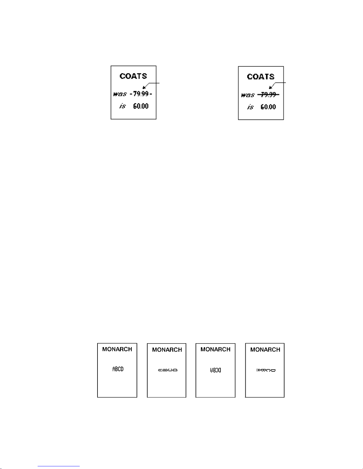
Field placement in the packet is an important consideration
when using field color attributes, because fields are imaged in
the order they are received. If a line field is defined before
the overlay (text or constant text) field, the line field is
blocked out by the overlay field, depending on the overlay
field’s color attribute. If a line field is defined after the overlay
field, the line field is not blocked out by the overlay field,
regardless of the overlay field’s color attribute.
T12. alignment Options:
Line field
blocked out by
opaque field
using attribute B
Line field not
blocked out by
transparent field
using attribute O
L
C
R
B
E
Use L, B, or E for any font.
T13. char rot Character rotation. The field or supply does not rotate, only
the characters do. Font 50 and downloaded TrueType fonts do
not support character rotation. Options:
0
1
2
3
Align on left side of field.
Center text within field (monospaced fonts only)
Align on right side of field (monospaced fonts only)
Align at midpoint of field
Align at endpoint of the field
Top of character points to top of field
(Use for scalable font)
Top of character points to left of field
Top of character points to bottom of field
Top of character points to right of field
3-6
Defining Fields
Page 71
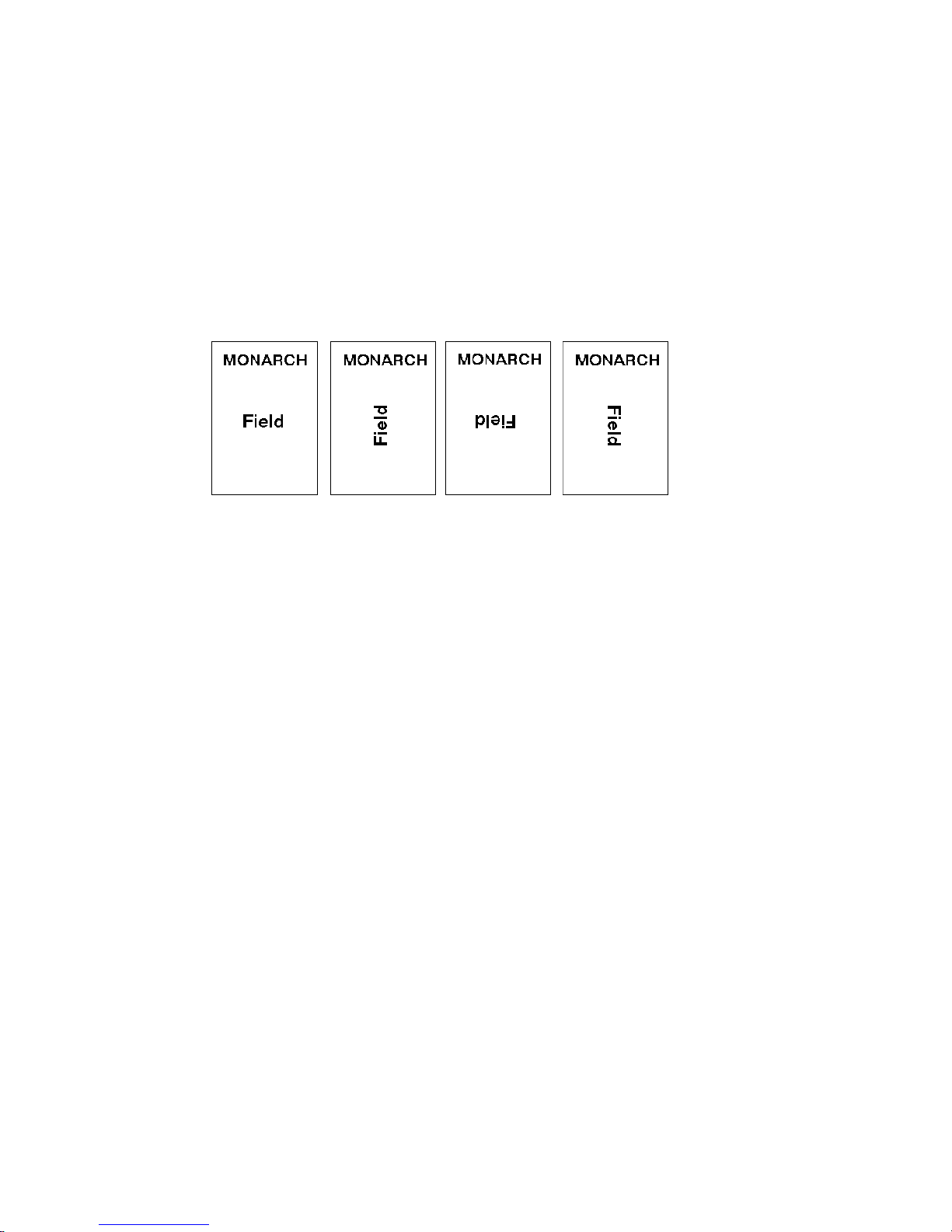
T14. field rot Field rotation. Field rotation rotates the whole field, not just
the characters. Rotation is affected by the pivot point, which
varies depending on how text is justified. Lower left corner of
field is the pivot point. Options:
0
1
2
3
T15. sym set Symbol set. Options:
0
1
100
101
102
103
104
105
106
107
437
850
852
855
857
860
1250
1251
1252
1253
1254
1255
1256
1257
1258
Top of field points to top of supply
Top of field points to left of supply
Top of field points to bottom of supply
Top of field points to right of supply
Internal Symbol Set
ANSI Symbol Set
Macintosh
Wingdings
UNICODE (user input) for particular mapping
BIG5 (user input) for UNICODE mapping
GB2312 (user input) for UNICODE mapping
SJIS (user input) for UNICODE mapping
Code Page 932 (Japanese Shift-JIS)
GB2312 (user input) for GB23212 mapping
Code Page 936 (Simplified Chinese)
BIG5 (user input) for BIG5 mapping
Code Page 950 (Traditional Chinese)
DOS Code Page 437 (Domestic)
DOS Code Page 850 (International)
DOS Code Page 852 (Latin 2)
DOS Code Page 855 (Russian)
DOS Code Page 857 (IBM Turkish)
DOS Code Page 860 (MS-DOS Portuguese)
Code Page 1250 (Latin 2)
Code Page 1251 (Cyrillic)
Code Page 1252 (Latin 1)
Code Page 1253 (Greek)
Code Page 1254 (Turkish)
Code Page 1255 (Hebrew)
Code Page 1256 (Arabic)
Code Page 1257 (Baltic)
Code Page 1258 (Vietnamese)
Defining Fields
3-7
Page 72

3-8 Defining Fields
Note: The CG Triumvirate typefaces support only the ANSI
and DOS Code Page 437 and 850 Symbol Sets. The
scalable font does not support Code Page 1256
(Arabic). Code pages 852-860 and 1250-1258 are for
downloaded TrueType fonts or the scalable font. Code
pages 102-107 require the memory expansion option
and a downloaded double-byte TrueType font.
TrueType fonts are designed to be regionally specific;
therefore, all code pages may not be supported in a
given font. See Appendix C, "Symbol Sets/ Code
Pages" for more information.
Example T,2,10,V,250,50,0,1,1,1,B,C,0,0,0¦
Defines a text field (field #2) with a variable length of up to 10
characters. The field begins at row 250, column 50. There is no
additional gap between characters, and the Standard font is used
without any additional magnification. The printing is black on white
and centered. No field or character rotation is used. The internal
symbol set is used.
Defining Bar Code Fields
Each bar code field requires a separate definition.
Syntax B,field#,# of char,fix/var,row,column,
font,density,height,text,alignment,field
rot¦
B1. B Bar Code Field.
B2. field# Unique number from 1-999 to identify this
field.
B3. # of char Maximum number of characters. If the bar
code uses a check digit, allow an extra
character for the check digit. The actual
maximum number of characters is limited by
the size of the label and bar code density.
Range: 0-2710. Quick Response (QR Code)
can use 299-2710 characters. Data Matrix
can use up to 2710 numeric characters or
2335 alphanumeric characters. See Appendix
A, "Samples," for more information.
Page 73
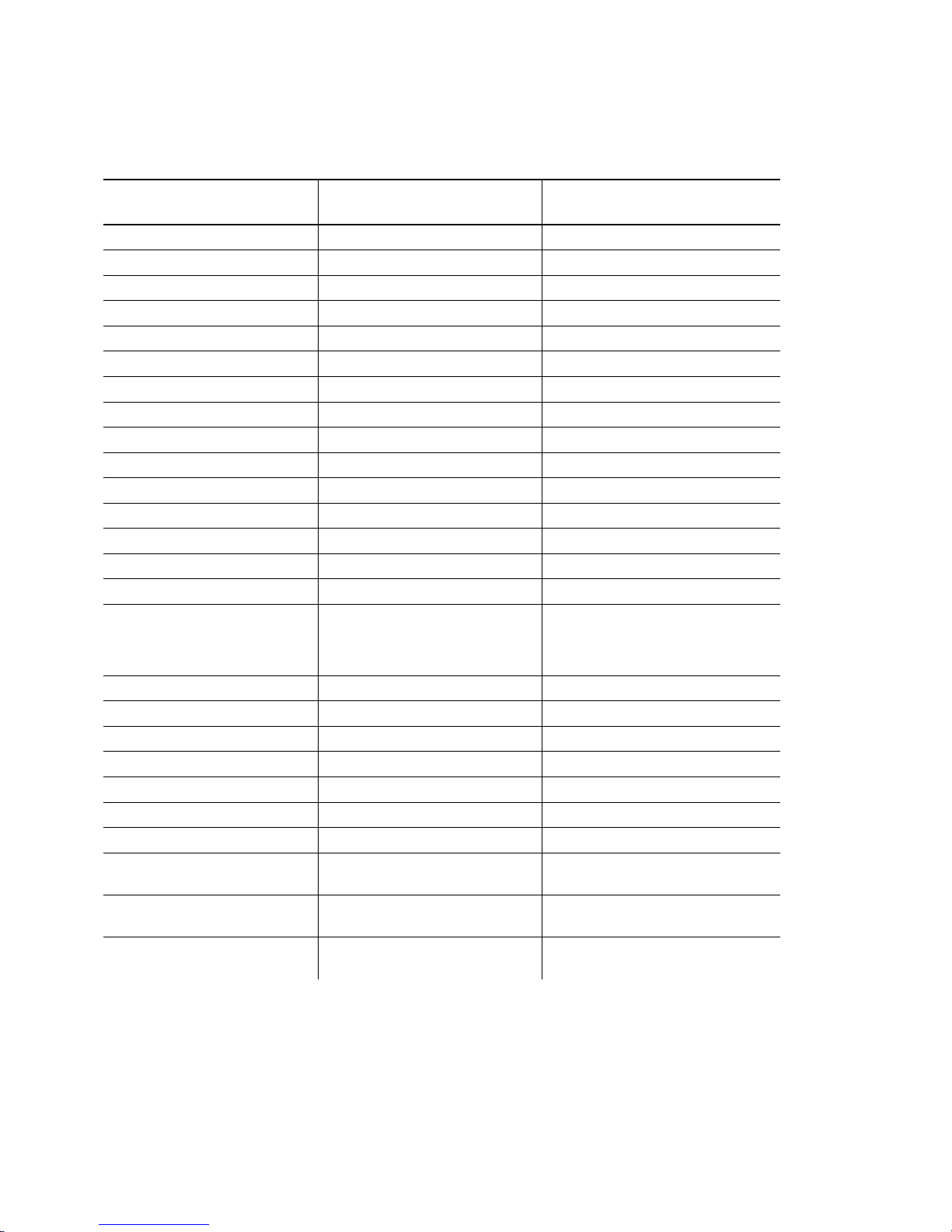
B4. fix/var Fixed (F) or variable (V) length field.
Bar Code Number of Characters Fixed or
UPCA
UPCA+2
UPCA+5
UPCA+Price CD
UPCE
UPCE+2
UPCE+5
EAN8
EAN8+2
EAN8+5
EAN13
EAN13+2
EAN13+5
EAN13+Price CD
POSTNET
Interleaved 2 of 5
or
Interleaved I 2 of 5 with
Barrier Bar
Code 39 or MOD43
Codabar (NW7)
Code 128
Code 16K
Code 93
MSI
PDF417
MaxiCode*
Data Matrix*
Quick Response*
depends on application F or V
0 to 93 (alphanumeric)
0 to 128 (numeric)
0 to 2335 (alphanumeric)
0 to 2710 (numeric)
1167 to 2710 (numeric)
707 to 2710 (alphanumeric)
12 F
14 F
17 F
12 F
7F
9F
12 F
8F
10 F
13 F
13 F
15 F
18 F
13 F
9 or 11 F
0 to 2710 V
0 to 2710 V
0 to 2710 V
0 to 2710 V
0 to 2710 V
0 to 14 F or V
0 to 2710 V
Variable
V
V
V
* For more information about MaxiCode, Data Matrix, and Quick Response, see Appendix
A, "Samples."
Defining Fields
3-9
Page 74
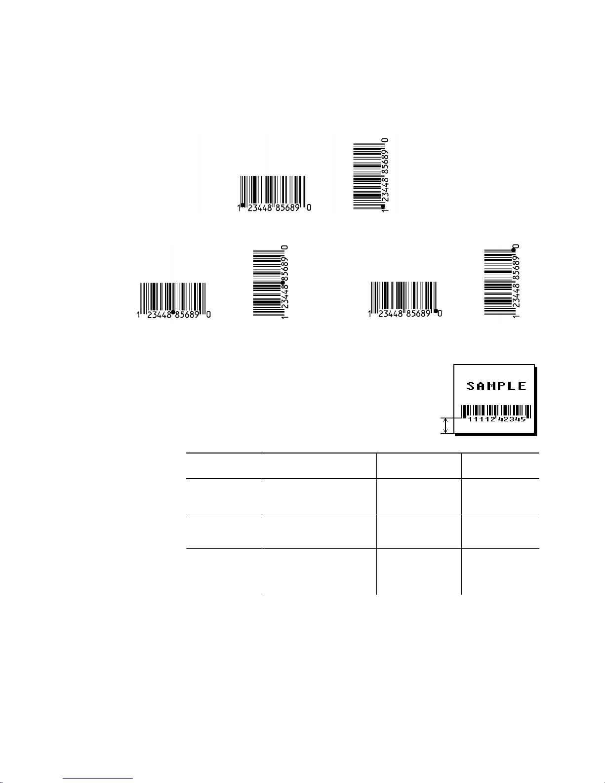
B5. row Distance from bottom of the print area to the pivot point of the
field. The pivot point varies, depending on how the field is
justified. Pivot points:
Left/Center/Right-Justified Fields
Balanced Fields End-Justified Fields
Remember to include text or numbers
that may appear with the bar code for
the row measurement.
3-10
Defining Fields
Printer Unit of Measure Row or
End Row
9825/
9855/
9860
9855/
9860
9855RFID
English (1/100 inch)
Metric (1/10 mm)
203 dpi Dots
English (1/100 inch)
Metric (1/10 mm)
300 dpi Dots
English (1/100 inch)
Metric (1/10 mm)
203 Dots
300 Dots
0-1599
0-4061
0-3246
0-1199
0-3045
0-3597
0-1299
0-3299
0-2637
0-3897
Column or
End Column
0-399
0-1013
0-810
0-399
0-1013
0-1197
0-399
0-1013
0-810
0-1197
Page 75

B6. column Distance from the lower left edge of the print area to the pivot
point. Use the previous table for values.
Allow a minimum of
the scan edge of bar code and label
edges or other data.
If using the optional verifier, allow a
minimum of 1.3 inches (33 mm)
between the bar code and the top of
the label. See "Determining the Print
Area" in Chapter 1 for more information.
B7. font Bar code. Options:
1
2
3
4
5
6
7
8
9
10
11
12
13
14
15
16
17
22
23
31
32
33
35
36
40
41
44
50
UPCA
UPCE
Interleaved 2 of 5
Code 39 (no check digit)
Codabar
EAN8
EAN13
Code 128
MSI
UPCA +2
UPCA +5
UPCE +2
UPCE +5
EAN8 +2
EAN8 +5
EAN13 +2
EAN13 +5
POSTNET
Code 93
Code 16K
PDF417
MaxiCode
Data Matrix (ECC-200)
Quick Response
Code 39 (MOD 43 check digit)
UPCA & Price CD
EAN13 & Price CD
Interleaved 2 of 5 with Barrier Bar
inch between
1/10
B8. density Bar code density. Use the following table for the bar code
density.
Defining Fields
3-11
Page 76
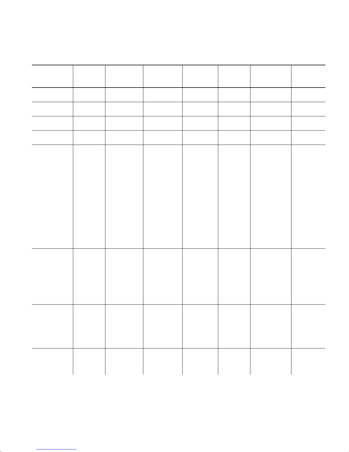
203 DPI Barcode Densities
Bar code
Ty p e
UPCA +2/+5
Price CD
UPCE
+2/+5
EAN8
+2/+5
EAN13+2/+5
Price CD
Interleaved
2 of 5
or I2of5
with Barrier
Bar
Density
Selector
2
4
2
4
2
4
2
4
1
2
3
4
5
6
7
8
9
10
11
12
Density
(% or cpi)
76
%
114
%
76
%
114
%
76
%
114
%
76
%
114
%
1.1
2.1
3.2
4.2
5.6
6.3
7.5
8.8
9.6
11.2
11.0
12.7
Narrow
Element
(dots/mils)
2/9.9
3/14.8
2/9.9
3/14.8
2/9.9
3/14.8
2/9.9
3/14.8
21/103.4
12/59.1
7/34.5
6/29.6
4/19.7
4/19.7
3/14.8
3/14.8
3/14.8
2/9.9
2/9.9
2/9.9
Narrow to
Wide Ratio
N/A 11 or 12
N/A 6 or 7
N/A 7 or 8
N/A 12 or 13
1:3.0
1:2.5
1:3.0
1:2.5
1:3.0
1:2.5
1:3.0
1:2.3
1:2.0
1:3.0
1:3.0
1:2.5
Data
Length
14/17
9/12
10/13
15/18
0 to 2710 8 0 to 9
Appearance
Codes
Available
1, 5, 6, 7 or 8 0 to 9
1, 5, 6, 7 or 8 0 to 9
1, 5, 6,7 or 8 0 to 9
1, 5, 6,7 or 8 0 to 9
Char
Set
Code 39 or
MOD43
(Extended
Code 39)
Codabar
(NW7)
Code 128 or
Code 16 K
Note:
The start (*) and stop (+) characters are automatically added for Code 39. Code 39,
density 12, produces a one-dot narrow bar. This density is intended for special
U.S.P.S. ACT-tag applications only. Synthetic supplies are recommended to produce
scannable bar codes.
13
1
2
3
4
6
7
11
12
20
2
3
4
5
7
8
9
20
4
6
8
14.5
1.4
1.7
3.5
4.2
6.3
7.0
3.9
12.7
3.0
2.1
3.0
4.6
5.1
8.4
9.2
10.1
3.5/7.0
4.4/8.7
5.8/11.7
8.7/17.5
2/9.9
10/49.3
8/39.4
4/19.7
3/14.8
2/9.9
2/9.9
4/19.7
1/4.9
5/24.6
8/39.4
6/29.6
4/19.7
4/19.7
2/9.9
2/9.9
2/9.9
5/24.6
4/19.7
3/14.8
2/9.9
1:2.0
1:2.5
1:2.5
1:2.5
1:3.0
1:3.0
1:2.5
1:2.0
1:3.0
1:2.2
1:3.0
1:2.5
1:2.5
1:2.0
1:3.0
1:2.5
1:2.0
N/A 0 to 2710 8 00H to 7FH
0 to 2710 8 SPACE
$%*+-./
0 to 9
A to Z
0 to 26 8 $+-./
0 to 9
a to d
3-12
Defining Fields
Page 77
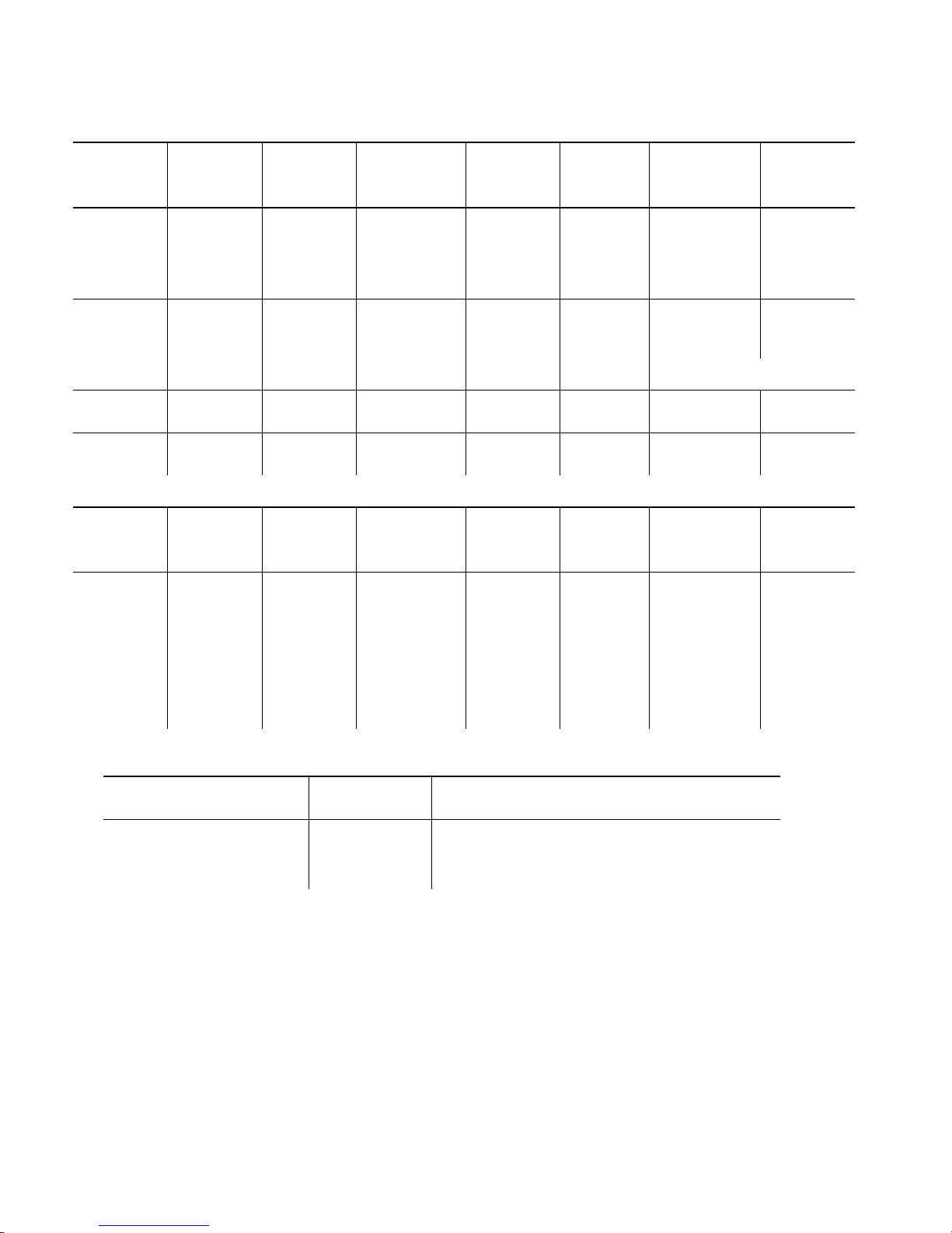
Bar code
Ty p e
Density
Selector
Density
(% or cpi)
Narrow
Element
(dots/mils)
Narrow to
Wide Ratio
Data
Length
Appearance
Codes
Available
Char Set
CODE 93 3
4
5
7
10
MSI 4
5
7
POSTNET 0 (fixed at
4.3 cpi)
MaxiCode 7 N/A N/A N/A 99 8 00H to
Bar code
Ty p e
PDF417 1
Density
Selector
2
3
4
5
6
7
8
9
3.7
4.5
5.6
7.5
11.2
4.2
5.6
7.2
24/118.2 10/49.3 4/19.7 (5
Element
Width
(dot/mils)
2/9.8
2/9.8
2/9.8
3/14.8
3/14.8
3/14.8
4/19.7
4/19.7
4/19.7
6/29.6
5/24.6
4/19.7
3/14.8
2/9.9
4/19.7
3/14.8
2/9.9
Row Height
(dots/mils)
2/9.8
4/19.7
6/29.6
3/14.8
6/29.6
9/44.3
4/19.7
8/39.4
12/59.1
N/A 0 to 2710 8 00H to
7FH
1:2.0
1:2.0
1:2.5
dot gap)
Aspect
Ratio
1:1
1:2
1:3
1:1
1:2
1:3
1:1
1:2
1:3
0 to 14 8 0 to 9
0,5,6,9 or118 0 to 9
FFH
Data
Length
0 to 2709 8 00H to
Appearance
Codes
Available
Char Set
FFH
Bar Code
Ty pe
Quick Response
(QR Code) Models 1 and 2
Note:
Density
Selector
0
Model 1: 0-1167 Numeric; 0-707
Alphanumeric; 0-486 (8-Bit); 0-299 Kanji
Model 2: 0-2710 Numeric; Alphanumeric and
8-Bit; 0-1817 Kanji
Data Length
Values in bold indicate the default.
Defining Fields
3-13
Page 78
203 DPI Barcode Densities
Bar Code Size
Row x Col.
Data Matrix
Square
symbols
10 x 10
12 x 12
14 x 14
16 x 16
18 x 18
20 x 20
22 x 22
24 x 24
26 x 26
32 x 32
36 x 36
40 x 40
44 x 44
48 x 48
52 x 52
64 x 64
72 x 72
80 x 80
88 x 88
96 x 96
104 x 104
120 x 120
132 x 132
144 x 144
Density
Selector
1
2
3
4
5
6
7
8
9
10
11
12
13
14
15
16
17
18
19
20
21
22
23
24
0 default (bar code size automatically determined by data)
Max. Data
Length
Num. X
Alphanum.
6 x 3
10 x 6
16 x 10
24 x 16
36 x 25
44 x 31
60 x 43
72 x 52
88 x 64
124 x 91
172 x 127
228 x 169
288 x 214
348 x 259
408 x 304
560 x 418
736 x 550
912 x 682
1152 x 862
1392 x 1042
1632 x 1222
2100 x 1573
2608 x 1954
2710 x 2335
App
Code
8 00H to FFH
Char
Set
3-14
Bar Code Size
Data Matrix
Rectangular
symbols
Note:
Defining Fields
Row x Col.
8 x 18
8 x 32
12 x 26
12 x 36
16 x 36
16 x 48
Density
Selector
25
26
27
28
29
30
0 default (bar code size automatically determined by data)
Max. Data
Length
Num. X
Alphanum.
10 x 6
20 x 13
32 x 22
44 x 31
64 x 46
98 x 72
App
Code
8 00H to FFH
Char
Set
The printers support printing a Data Matrix symbol with an X-dimension
of 13 mils or greater (3 dots @203 dpi). If you use a denser bar code,
make sure the bar code scans in your particular application. Paxar
"premium" supplies and increasing the print contrast are recommended
for denser bar codes. Depending on your application, additional
densities are available.
Page 79
300 DPI Barcode Densities
Bar code
Ty pe
UPCA +2/+5
Price CD
UPCE
+2/+5
EAN8
+2/+5
EAN13+2/+5
Price CD
Interleaved
2 of 5
or I2of5
with Barrier
Bar
Density
Selector
2
4
2
4
2
4
2
4
1
2
3
4
5
6
7
8
9
10
11
12
Density
(% or cpi)
77
%
103
%
77
%
103
%
77
%
103
%
77
%
103
%
1.1
2.1
3.3
4.2
5.6
6.2
8.3
9.4
9.9
11.1
11.1
13.0
Narrow
Element
(dots/mils)
3/10
4/13.3
3/10
4/13.3
3/10
4/13.3
3/10
4/13.3
31/103.4
18/60.1
10/33.4
9/30.0
6/20.0
6/20.0
4/13.3
4/13.3
4/13.3
3/10.0
3/10.0
3/10.0
Narrow to
Wide Ratio
1:2.0 11 or 12
1:2.0 6 or 7
1:2.0 7 or 8
1:2.0 12 or 13
1:3.0
1:2.5
1:3.0
1:2.4
1:3.0
1:2.5
1:3.0
1:2.5
1:2.3
1:3.0
1:3.0
1:2.3
Data
Length
14/17
9/12
10/13
15/18
0 to 2710 8 0 to 9
Appearance
Codes
Available
1, 5, 6, 7 or 8 0 to 9
1, 5, 6, 7 or 8 0 to 9
1, 5, 6,7 or 8 0 to 9
1, 5, 6,7 or 8 0 to 9
Char
Set
Code 39 or
MOD43
(Extended
Code 39)
Codabar
(NW7)
Code 128 or
Code 16 K46
Note:
The start (*) and stop (+) characters are automatically added for Code 39. Code 39,
density 12, produces a one-dot narrow bar. This density is intended for special U.S.P.S.
ACT-tag applications only. Synthetic supplies are recommended to produce scannable
bar codes.
13
1
2
3
4
6
7
11
12
20
2
3
4
5
7
8
9
8
20
14.3
1.4
1.7
3.4
4.7
6.2
7.1
3.8
11.5
3.1
2.3
3.4
5.0
5.6
9.1
10.4
11.1
4.5
6.8
9.1
3.9
3/10.0
15/50.0
12/40/0
6/20.0
4/13.3
3/10.0
3/10.0
6/20.0
2/6.7
7/23.4
12/40.0
9/30.0
6/20.0
6/20.0
3/10.0
3/10.0
3/10.0
6/20.0
4/13.3
3/10.0
7/23.4
1:2.0
1:2.5
1:2.3
1:2.5
1:3.0
1:3.0
1:2.3
1:2.0
1:3.0
1:2.3
1:3.0
1:2.4
1:2.5
1:2.0
1:3.0
1:2.3
1:2.0
N/A 0 to 2710 8 00H to 7FH
0 to 2710 8 SPACE
$%*+-./
0 to 9
A to Z
0 to 2710 8 $+-./
0 to 9
a to d
Defining Fields
3-15
Page 80
Bar code
Ty p e
Density
Selector
Density
(% or cpi)
Narrow
Element
(dots/mils)
Narrow to
Wide Ratio
Data
Length
Appearance
Codes
Available
Char Set
CODE 93 3
4
5
7
10
MSI 4
5
7
POSTNET 0 (fixed at
4.2 cpi)
MaxiCode 7 N/A N/A N/A 99 8 00H to
Bar code
Ty p e
PDF417 1
Density
Selector
2
3
4
5
6
7
8
9
3.7
4.8
5.6
8.3
11.1
4.2
6.2
7.5
24/118.2 15/50.0 6/20.0 (5
Element
Width
(dot/mils)
3/10.0
3/10.0
3/10.0
4/13.3
4/13.3
4/13.3
6/20.0
6/20.0
6/20.0
9/30.0
7/23.4
6/20.0
4/13.3
3/10.0
6/20.0
4/13.3
3/10.0
Row Height
(dots/mils)
3/10.0
6/20.0
9/30.0
4/13.3
9/30.0
12/40.0
6/20.0
12/40.0
18/60.0
N/A 0 to 2710 8 00H to
7FH
1:2.0
1:2.0
1:2.3
dot gap)
Aspect
Ratio
1:1
1:2
1:3
1:1
1:2
1:3
1:1
1:2
1:3
0 to 2710 8 0 to 9
0,5,6,9 or118 0 to 9
FFH
Data
Length
0 to 2709 8 00H to
Appearance
Codes
Available
Char Set
FFH
Bar Code
Ty pe
Quick Response
(QR Code) Models 1 and 2
3-16
Defining Fields
Note:
Density
Selector
0
Model 1: 0-1167 Numeric; 0-707
Alphanumeric; 0-486 (8-Bit); 0-299 Kanji
Model 2: 0-2710 Numeric; Alphanumeric and
8-Bit; 0-1817 Kanji
Data Length
Values in bold indicate the default.
Page 81
300 DPI Barcode Densities
Bar Code Size
Row x Col.
Data Matrix
Square
symbols
10 x 10
12 x 12
14 x 14
16 x 16
18 x 18
20 x 20
22 x 22
24 x 24
26 x 26
32 x 32
36 x 36
40 x 40
44 x 44
48 x 48
52 x 52
64 x 64
72 x 72
80 x 80
88 x 88
96 x 96
104 x 104
120 x 120
132 x 132
144 x 144
Density
Selector
1
2
3
4
5
6
7
8
9
10
11
12
13
14
15
16
17
18
19
20
21
22
23
24
0 default (bar code size automatically determined by data)
Max. Data
Length
Num. X
Alphanum.
6 x 3
10 x 6
16 x 10
24 x 16
36 x 25
44 x 31
60 x 43
72 x 52
88 x 64
124 x 91
172 x 127
228 x 169
288 x 214
348 x 259
408 x 304
560 x 418
736 x 550
912 x 682
1152 x 862
1392 x 1042
1632 x 1222
2100 x 1573
2608 x 1954
2710 x 2335
App
Code
8 00H to FFH
Char
Set
Bar Code Size
Row x Col.
Data Matrix
Rectangular
symbols
Note:
The printers support printing a Data Matrix symbol with an X-dimension
8 x 18
8 x 32
12 x 26
12 x 36
16 x 36
16 x 48
of 13 mils or greater (3 dots @203 dpi). If you use a denser bar code,
make sure the bar code scans in your particular application. Paxar
"premium" supplies and increasing the print contrast are recommended
for denser bar codes. Depending on your application, additional
densities are available.
Density
Selector
25
26
27
28
29
30
0 default (bar code size automatically determined by data)
Max. Data
Length
Num. X
Alphanum.
10 x 6
20 x 13
32 x 22
44 x 31
64 x 46
98 x 72
App
Code
8 00H to FFH
Char
Set
Defining Fields
3-17
Page 82

B9. height Bar code height, in 1/100 inches, 1/10 mm, or dots. Minimum
values:
English
Metric
203 Dots
300 Dots
POSTNET, PDF417, and MaxiCode bar codes have a fixed
height. Always use 0 for these bar codes.
For Data Matrix and QR Code, the printer determines the size
of the symbol, but the user’s scanner determines the
functional size (minimum height) of the symbol. Small Data
Matrix and QR Codes may not be scannable. The Data Matrix
and QR Code’s height depends on the number entered for this
parameter. For example, if you select 80, the symbol could be
smaller than 0.80," but it will not be greater than the amount
specified in this parameter. The symbol arranges the data
according to rows and columns within the specified height.
B10. text Appearance of text with bar code. For UPC and EAN only use
. For all others, use 8, except where noted. Options:
0-7
0
1
2
3
5
6
7
8
Default
MaxiCode Mode 0 (obsolete)
QR Code Model 2
No check digit or number system
QR Code Model 1
MaxiCode Mode 2 (Numeric Postal Code)
QR Code Model 2
MaxiCode Mode 3 (Alphanumeric Postal Code)
Number system at bottom, no check digit
Check digit at bottom, no number system
Check digit and number system at bottom
No text, bar code only
MaxiCode (autodetect modes 0, 2, or 3) and Data Matrix
19
48
38
57
B11. alignment Choose L, R, C, B or E to align the bar code data correctly in
3-18
Defining Fields
the field. B centers variable width bar codes, which may not
allow pad-character centering (Code 128, Code 39, etc.)
right justifies variable width bar codes. MaxiCode, Data
Matrix, and QR Code must use L.
E
Page 83

B12. field rot Field rotation. Field rotation rotates the whole field, not just
the characters. Rotation is affected by the pivot point, which
varies depending on how text is justified. Lower left corner of
field is the pivot point. Options:
Top of field points to top of supply
(Use for Maxicode)
Top of field points to left of supply
Top of field points to bottom of supply
Top of field points to right of supply
Serial bar codes with an 8-dot narrow element do not
automatically print at 2.5 IPS. Serial bar codes
printed at speeds greater than 2.5 IPS may not scan
properly.
Example
0
1
2
3
Note:
B,3,12,V,150,40,1,2,80,7,L,0 p
Defines a bar code field (field #3) with 12 characters of variable
length starting at row 150, column 40. A UPCA bar code with a
density of 2 and a height of 80 is used. The check digit and
number system are shown at the bottom. The bar code is left
aligned without any field rotation.
Defining Non-Printable Text Fields
Non-printable text fields allow you to enter data without printing it
in its entered form. Typically, non-printable fields "hold" data that
later combines with other fields to form a merged field. Define
non-printable text fields before you define the field where the
information prints.
When you copy this field into another field, the maximum number
of characters for the final field is
2710
. Allow only as many
characters as you need, because extra characters use up space.
Also, if you are copying into a bar code field, the maximum
number of characters in the destination bar code is determined by
the bar code specification (UPCA-12, EAN-13, etc.). You need to
apply field options to manipulate the text entered in this field. For
example, you may want to copy data from this field into another
field. See "Option 4 Copy Data" in Chapter 4 for more information.
Defining Fields
3-19
Page 84

In the following example, data is entered into four non-printable
fields and merged to form field 5, and is then printed as a bar
code. See "Merging Fields" in Chapter 4 for more information.
Field Data Field Type
1 20374 Non-printable
2 339 Non-printable
3 8 Non-printable
4 15 Non-printable
5 20374339815 Bar Code
Each non-printable text field requires a separate definition.
Syntax
D1. D Non-Printable Text Field.
D2. field# Unique number from
D3. # of char Maximum number of characters in this field:
Example
D,field#,# of char p
0-999
D,4,20 p
assigned to this field.
0-2710
.
Defines a non-printable text field (field #4) with a maximum of 20
characters.
Defining Constant Text Fields
A constant text field is a set of fixed characters that prints on all
labels. Define each constant text field separately. This field is
not assigned a field number, but is counted as a field (keep this in
mind, as the printer allows a maximum of
1000
characters in this field cannot be changed by batch data. Field
options do not apply to constant text fields. Mark the pivot point
of your field. This varies depending on how your field is justified.
fields). The
3-20
Defining Fields
Page 85
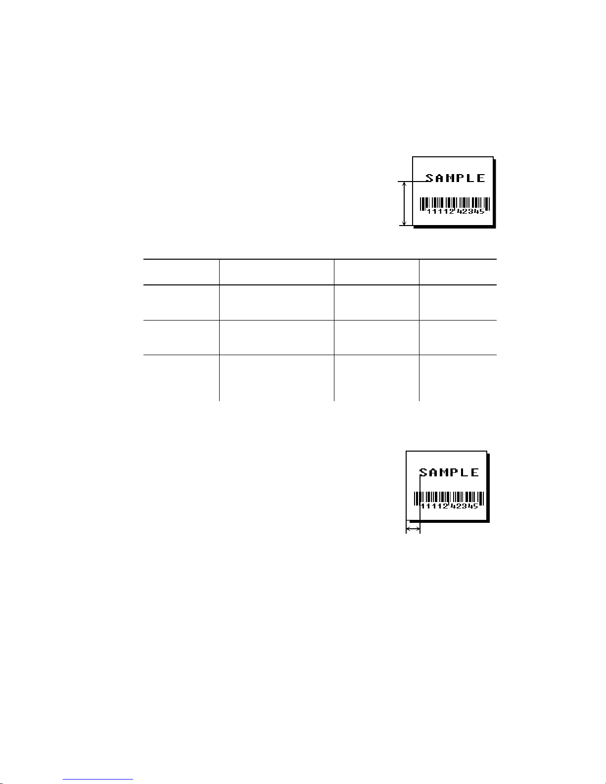
Syntax
C,row,column,gap,font,hgt mag,
wid mag,color,alignment,char rot,
field rot,"fixed char",sym set p
C1. C Constant Text Field.
C2. row For monospaced fonts, distance from
bottom of print area to the pivot point. For
proportionally spaced fonts, distance from
bottom of print area to baseline of
characters in the field. (Bottom exits the
printer first.)
Printer Unit of Measure Row or
End Row
9825/
9855/
9860
9855/
9860
9855RFID
English (1/100 inch)
Metric (1/10 mm)
203 dpi Dots
English (1/100 inch)
Metric (1/10 mm)
300 dpi Dots
English (1/100 inch)
Metric (1/10 mm)
203 Dots
300 Dots
0-1599
0-4061
0-3246
0-1199
0-3045
0-3597
0-1299
0-3299
0-2637
0-3897
Column or
End Column
0-399
0-1013
0-810
0-399
0-1013
0-1197
0-399
0-1013
0-810
0-1197
C3. column Distance from the lower left edge of the print area to the pivot
point. Use the previous table for values.
C4. gap Number of dots between characters.
Range:
0-99
dots.
Any number other than 0 or the default
number affects your field width. Default
spacing:
Standard
Reduced
Bold
OCRA-like
3 dots
1 dot
3 dots
3 dots
CG Triumvirate
Typeface Bold
CG Triumvirate Typeface
varies with each letter
varies with each letter
Defining Fields
3-21
Page 86

C5. font Style of font. Options:
Standard
1
Reduced
2
Bold
3
OCRA-like
4
HR1
5
HR2
6
Or a valid downloaded font selector number.
Fonts 5 and 6 are for numeric data only.
The CG Triumvirate typefaces support only the ANSI and
DOS Code Page 437 and 850 Symbol Sets. See Appendix C
for more information.
CG Triumvirate Typeface Bold
10
CG Triumvirate Typeface
11
7 pt. CG Triumvirate Typeface
15
9 pt. CG Triumvirate Typeface
16
11 pt. CG Triumvirate Typeface
17
15 pt. CG Triumvirate Typeface
18
EFF Swiss Bold (TrueType® Scalable)
50
PaxarSymbols (version 5.0 or greater)
56
C6. hgt mag Height magnifier,
TrueType fonts). Use a magnifier of 1 with proportionally
spaced fonts, because characters lose smoothness at higher
magnifications. See Appendix B, "Fonts," for more
information about fonts.
C7. wid mag Width magnifier,
TrueType fonts). Proportionally spaced fonts do not have a
set width. To estimate the size of your field, use the letter "W"
for the widest field or an "L" for an average width field. Find
your selected font and the desired width in Appendix B,
"Fonts."
Note:
C8. color There are two types of field color overlay attributes:
Transparent The overlay field (text or constant text) does
Opaque The overlay field blocks out (or "erases")
Options for standard printer fonts:
To use larger point sizes (greater than 60), you must
reconfigure memory and increase the size of the
scalable (vector) fonts buffer.
not block out (or "erase") existing fields.
existing fields.
B
D/R/W
O
Opaque, Normal, Black, Normal
Opaque, Normal, White, Normal
Transparent, Normal, Black, Normal
times (4-
1-7
times (4-
1-7
for scalable/downloaded
255
for scalable/downloaded
255
3-22
Defining Fields
Options for the Scalable Font:
A/N
B/O
D/W
E/S
F/T
Transparent, Normal, Black, Bold
Transparent, Normal, Black, Normal
Opaque, Normal, White, Normal
Transparent, Italics, Black, Bold
Transparent, Italics, Black, Normal
Page 87

Field placement in the packet is an important consideration
when using field color attributes, because fields are imaged in
the order they are received. If a line field is defined before
the overlay (text or constant text) field, the line field is
blocked out by the overlay field, depending on the overlay
field’s color attribute. If a line field is defined after the overlay
field, the line field is not blocked out by the overlay field,
regardless of the overlay field’s color attribute.
C9. alignment Options:
L
C
R
B
E
Use L, B, or E for any font.
C10. char rot Character rotation. The field or supply does not rotate, only
the characters do. Options:
0
1
2
3
Note:
C11. field rot Field rotation. Field rotation rotates the whole field, not just
the characters. Rotation is affected by the pivot point, which
varies depending on how text is justified. Lower left corner of
field is the pivot point.
Options:
Align on left side of field.
Center text within field (monospaced fonts only)
Align on right side of field (monospaced fonts only)
Align at midpoint of field
Align at endpoint of the field
Top of character points to top of field
(Use for scalable font.)
Top of character points to left of field
Top of character points to bottom of field
Top of character points to right of field
Font 50 and downloaded TrueType fonts do not
support character rotation.
0
1
2
3
C12. "fixed char" Fixed characters to appear in the field. Maximum
characters. Enclose in quotation marks.
Top of overlay points to top of supply
Top of overlay points to left of supply
Top of overlay points to bottom of supply
Top of overlay points to right of supply
2710
Defining Fields
3-23
Page 88

3-24 Defining Fields
C13. sym set Symbol set. Options:
0 Internal Symbol Set
1 ANSI Symbol Set
100 Macintosh
101 Wingdings
102 UNICODE (user input) for particular mapping
103 BIG5 (user input) for UNICODE mapping
104 GB2312 (user input) for UNICODE mapping
105 SJIS (user input) for UNICODE mapping
Code Page 932 (Japanese Shift-JIS)
106 GB2312 (user input) for GB23212 mapping
Code Page 936 (Simplified Chinese)
107 BIG5 (user input) for BIG5 mapping
Code Page 950 (Traditional Chinese)
437 DOS Code Page 437 (Domestic)
850 DOS Code Page 850 (International)
852 DOS Code Page 852 (Latin 2)
855 DOS Code Page 855 (Russian)
857 DOS Code Page 857 (IBM Turkish)
860 DOS Code Page 860 (MS-DOS Portuguese)
1250 Code Page 1250 (Latin 2)
1251 Code Page 1251 (Cyrillic)
1252 Code Page 1252 (Latin 1)
1253 Code Page 1253 (Greek)
1254 Code Page 1254 (Turkish)
1255 Code Page 1255 (Hebrew)
1256 Code Page 1256 (Arabic)
1257 Code Page 1257 (Baltic)
1258 Code Page 1258 (Vietnamese)
The CG Triumvirate typefaces support only the
ANSI and DOS Code Page 437 and 850 Symbol
Sets. The scalable font does not support Code
Page 1256 (Arabic). Code pages 852-860 and
1250-1258 are for downloaded TrueType fonts
or the scalable font. Code pages 102-107
require the memory expansion option and a
downloaded double-byte TrueType font.
TrueType fonts are designed to be regionally
specific; therefore, all code pages may not be
supported in a given font. See Appendix C,
"Symbol Sets/ Code Pages" for more
information.
Example C,30,10,0,1,1,1,B,L,0,0,"MADE IN USA",0¦
Defines a constant text field starting at row 30, column 10. It does
not have any additional inter-character gap. The Standard font is
used without any additional magnification. The printing is black on
white and left justified. No field or character rotation is used.
Page 89

Defining Line Fields
Use lines to form borders and mark out original prices. Define
each line separately. This field is not assigned a field number, but
is counted as a field (keep this in mind, as the printer allows a
maximum of
1000
length and a thickness up to 99 dots, as long as the solid black
print does not exceed 30 percent of any given square inch of the
label.
Line Types
You can create horizontal and vertical lines. Define lines as
fields per format). You can define any line
Segments
Vectors
Choose starting point and ending point.
Choose starting point, angle, and length of
line.
Syntax
L1. L Line Field.
L2. type Type of line. Only vertical and horizontal lines are
L3. row Distance from bottom of print area to the starting point.
L,type,row,column,angle/end row,length/
end col,thickness,"pattern" p
supported. Options:
S
V
Segment. Choose starting
point and ending point.
Vector. Choose starting
point, angle, and length.
Defining Fields
3-25
Page 90
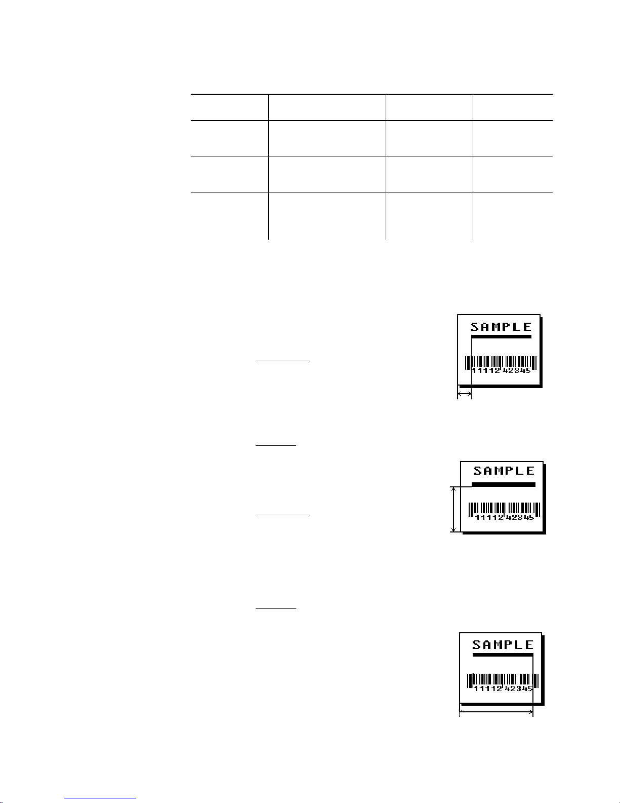
Printer Unit of Measure Row or
End Row
9825/
9855/
9860
9855/
9860
9855RFID
English (1/100 inch)
Metric (1/10 mm)
203 dpi Dots
English (1/100 inch)
Metric (1/10 mm)
300 dpi Dots
English (1/100 inch)
Metric (1/10 mm)
203 Dots
300 Dots
0-1599
0-4061
0-3246
0-1199
0-3045
0-3597
0-1299
0-3299
0-2637
0-3897
Column or
End Column
0-399
0-1013
0-810
0-399
0-1013
0-1197
0-399
0-1013
0-810
0-1197
L4. column Distance from left edge of the print area to line origin. Use
the previous table for values.
L5. angle/
end row
L6. length/
end col
If Using Segments
Row location of ending point. Measure
from bottom of print area. Ranges same
as row above. On horizontal lines, this
value must match item L3.
If Using
Vec tors
Angle of line. Options: 0, 90,
180
, or
270
.
If Using Segments
Column location of end point. Measure from left edge of print
area. Ranges same as column above. On vertical lines, this
value must match parameter L4.
If Using
Vec tors
Length of the line in selected units. Use
the previous table for values.
3-26
Defining Fields
Page 91
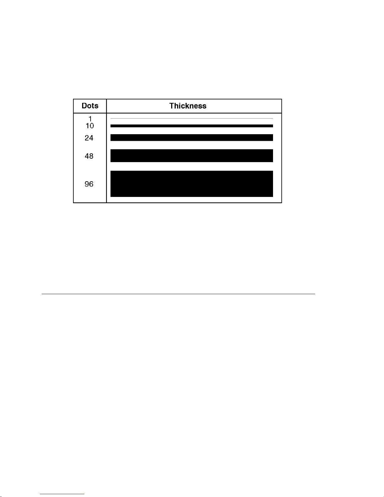
L7. thickness Using the chart below for reference, write the desired line
thickness (1 to 99) in box L7. Line thickness fills upward on
horizontal lines, or to the right on vertical lines. Measured in
dots.
L8. "pattern" Line pattern. Enter "".
Example
L,S,110,30,110,150,10,"" p
Defines a horizontal line field as a segment starting at row 110,
column 30 and ending at row 110, column 150. The line
thickness is 10 dots.
Defining Box Fields
Use boxes to form borders or highlight items of interest. Define
each box field separately. This field is not assigned a field
number, but is counted as a field (keep this in mind, as the printer
allows a maximum of
1000
line length and a thickness up to 99 dots, as long as the solid
black print does not exceed 30 percent of any given square inch
of the label.
fields per format). You can define any
Defining Fields
3-27
Page 92
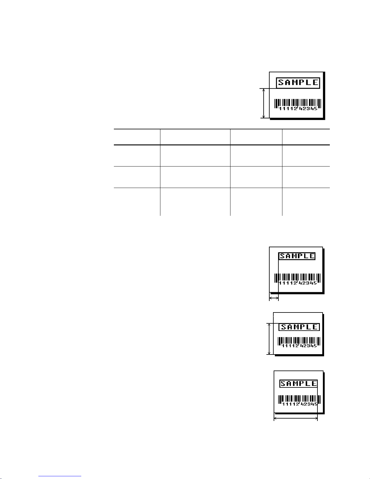
Syntax
Q,row,column,end row,end col,thickness,
"pattern" p
Q1. Q Box (Quadrilateral) Field.
Q2. row Distance from bottom of print area to
lower left corner of box.
Printer Unit of Measure Row or
End Row
9825/
9855/
9860
9855/
9860
9855RFID
English (1/100 inch)
Metric (1/10 mm)
203 dpi Dots
English (1/100 inch)
Metric (1/10 mm)
300 dpi Dots
English (1/100 inch)
Metric (1/10 mm)
203 Dots
300 Dots
0-1599
0-4061
0-3246
0-1199
0-3045
0-3597
0-1299
0-3299
0-2637
0-3897
Q3. column Distance from left edge of print area to
lower left corner of box.
Use the previous table for values.
Q4. end row Distance from bottom of print area to
upper right corner of box.
Ranges same as row.
Column or
End Column
0-399
0-1013
0-810
0-399
0-1013
0-1197
0-399
0-1013
0-810
0-1197
Q5. end col Distance from left edge of print area to
3-28
Defining Fields
upper right corner of box.
Ranges same as column.
Page 93
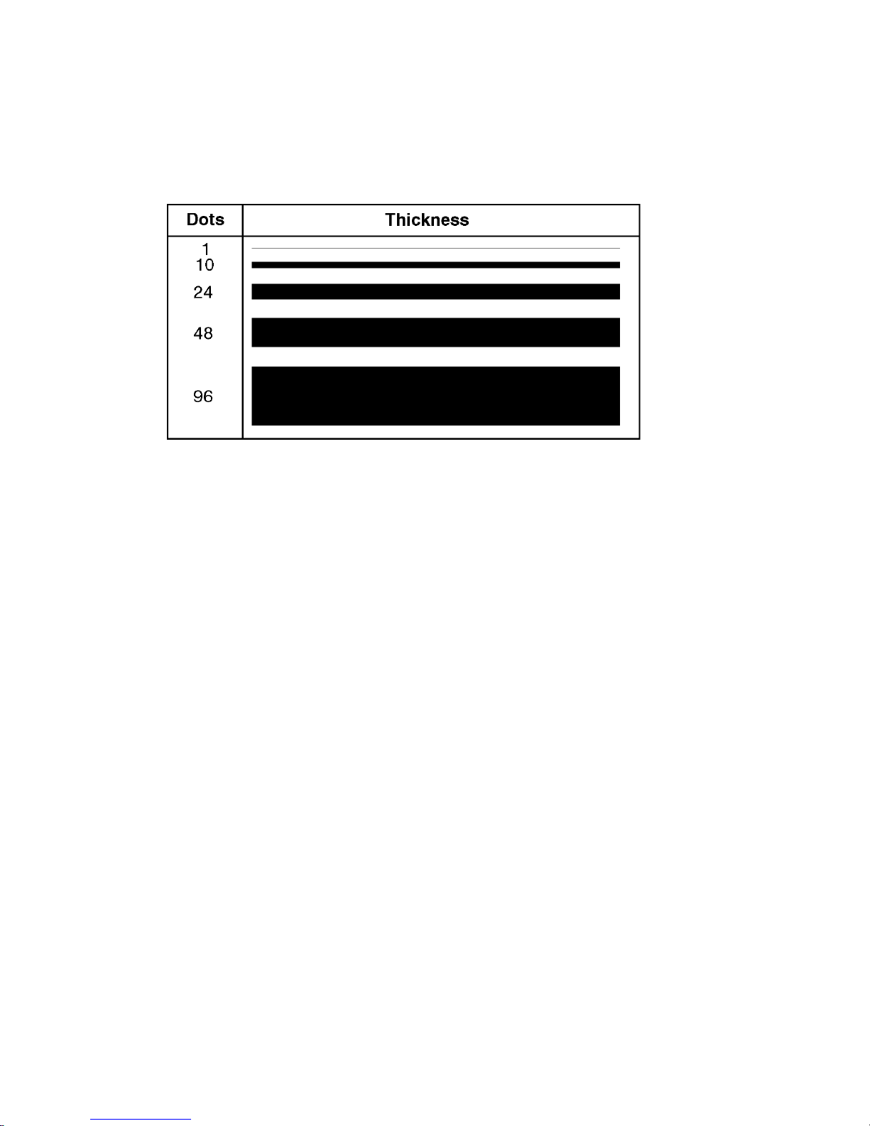
Q6. thickness Using the chart below for reference, write the desired line
thickness (
your boxes do not overwrite other fields. Measured in dots.
Q7. "pattern" Line pattern. Enter "".
1 to 99
) in box Q6. Boxes fill inward, so make sure
Example
Q,240,30,270,150,3,"" p
Defines a box field starting at row 240, column 30. It ends at row
270, column 150. It has a thickness of 3 dots.
Defining Fields
3-29
Page 94

Defining Verifier Fields
The verifier field in a format references the verifier configuration
packet ID to use for this particular format. The verifier field
allows you to specify a different verifier configuration packet for
each format, regardless of the format number. See "Defining a
Verifier Configuration Packet," in Chapter 2 for more information.
The verifier field allows you to specify a different verifier
configuration packet for each of your formats.
If you do not specify a particular verifier configuration packet, the
last sent verifier configuration packet is used.
Syntax
V1. V Verifier Field.
V2. vfrID Unique number from
Example
V,vfrID p
1-999
packet to use with this format.
F,25,A,R,M,508,508,"FMT-25" p
V,3 p
B,1,12,F,110,115,1,2,120,5,L,0 p
to identify the verifier configuration
Specifies verifier configuration packet #3 starting with format 25
until another verifier configuration packet is specified.
3-30
Defining Fields
Page 95

Defining Fields 3-31
Defining the RFID Data Field
The RFID Data Field contains the information you want
programmed into the RFID tag. The syntax of the RFID Data Field
is similar to the standard non-printable text field format. RFID is
only supported on the 9855 printer. Printing over the RFID tag
(or transponder) causes printing irregularity. For more information
about RFID, refer to the Multi-Protocol Application Notes, available
on our Web site.
♦ With version 2.8 or greater firmware, the printer supports both
64-bit and 96-bit RFID tags.
♦ With version 3.2 or greater firmware, the printer supports multi-
protocol encoding, including Class 1 Generation (Gen) 1 and
Class 1 Generation (Gen) 2 supplies.
♦ With version 5.0 or greater firmware, the printer accepts EPC
data following the guidelines in the EPCglobal
Tag Data
Standards, which conforms to the EPC
Radio Frequency
Identity Protocols Class 1 Generation 2 UHF RFID Protocol for
Communications at 860-960MHz Standards (Air Interface
Protocol). See "Using Expanded Gen2 Data" in Chapter 6,
"Printing," for more information.
Syntax X,field#,# of char,data_type¦
X1. X RFID Data Field.
X2. field# Unique number from 0-999 assigned to this
field.
X3. # of char This number must be equal to or greater than
the total number of characters in the RFID
Data Field.
Range: 0-2710. The amount varies according
to your RFID data and protocol. For example,
C1Gen2 can be 96-Bits, plus the access
password, lock code, etc.
Note: An error 715 occurs if the printer
does not receive the correct amount
of data.
You can pad data to make sure you
have the correct amount of bits.
See "Option 30," in Chapter 4 for
more information.
Page 96
X4. data_type Data type. Options:
0
1
2
3
We recommend using ASCII Hex for compatibility with multiple
host applications.
For example, the letter A has a decimal value of 65 in the
ASCII table. The hex (base 16) equivalent of decimal (base
10) is 41. Hex 41 in binary notation is 01000001.
Data Type Character MPCL Batch Data for a 96-bit RFID tag
ASCII Hex 41 "414141414141414141414141"
ASCII A "AAAAAAAAAAAA"
ASCII Binary 01000001
Hex ~065 "~065~065~065~065~065~065~065~065~065~065~065~065"
ASCII Hex - default (ASCII representation of Hex)
Use characters A to F and 0 to 9.
ASCII
ASCII Binary (ASCII representation of Binary)
Use characters 0 and 1.
Hex
"010000010100000101000001010000010100000101000001
010000010100000101000001010000010100000101000001"
Example
X,5,24,0 p
Defines an RFID Data Field (field #5) with exactly 24 ASCII Hex
characters for a 96-bit RFID tag.
3-32
Defining Fields
Page 97

DEFINING FIELD OPTIONS
This chapter provides a reference for defining
N
field options in formats
N
check digit packets.
Note: When using multiple options on the printer, remember that options
are processed in the order they are received.
4
Defining Field Options
4-1
Page 98

Applying Field Options
Field options further define text, bar code, and non-printable text
fields. The text, constant text, or bar code field must be
previously defined before you can apply any field option to it.
Define options immediately after the field to which they apply.
Combining Field Options
You can use more than one option with most fields. For example,
you can use Option 4 to copy data from another field, and then
use Option 30 to pad the field. When you use multiple options for
the same field, you must place the options in the order you want
to apply them to your format.
Restrictions
Some options cannot be used together. For example,
incrementing (Option 60) and price field (Option 42) options
cannot be applied to the same field. Refer to the following
sections addressing individual options for specific combinations to
avoid.
Option 4 (copy a field) is the only option that can be repeated for
a single field.
Example
Syntax
R1. R Indicates field option header.
R2. option# Option number:
4-2
Defining Field Options
R,1,3,1,3,1,1 p
R,option#,parameter...parameter p
1 Define fixed characters
2 Data type restrictions (9855/9860)
3 Data entry template (9855/9860)
4 Copy data from previous field
5 Define data entry sources (9855/9860)
Page 99
20 Define data entry prompts (9855/9860)
21 Define extended field names (9855 XML-enabled printer)
30 Pad data to left or right with specified character
31 Generate check digit
42 Format as a price field
50 Define bar code densities
51 Define security and truncation of PDF417 bar codes
52 Define width or length of PDF417 bar codes
60 Define incrementing or decrementing field
61 Reimage fields
62 Do not scan/verify a particular bar code
R3. parameter(s) Varies per option. See the following option descriptions.
Applying Options to the RFID Data Field
All the normal field options (copy, merge, pad, increment, etc.)
can be applied to the RFID Data Field. However, certain
restrictions may apply.
N
To copy, merge, pad, or increment data in the RFID Data Field,
the copied/merged/padded/incremented data must be in the
same format specified in the RFID Data Field. For example,
to copy data into the RFID Data Field using ASCII Hex, the
field being copied must be in ASCII Hex format; otherwise,
unexpected results may occur.
N
When incrementing the RFID Data Field, see the following
table for an explanation of how the field increments.
Data Type How the Field Increments
ASCII Hex 0 to F (0123456789ABCDEF), then back to 0
ASCII Binary 0 to 1 or 1 to 0
ASCII or Hex next position in 0 to 255 range
N
If Option 60 (Increment Field) contains the character "D" to
decrement, it is ignored and the field is instead incremented
by one.
N
When incrementing the RFID Data Field, the only valid value
to increment is by one.
N
Use caution when incrementing an RFID field if data is coming
directly from your host because the field must be incremented
in ASCII Hex (or other specified data type).
Defining Field Options
4-3
Page 100

Option 1 (Fixed Data)
Fixed data is information (a company name or store number) you
want to print on all labels. You can define fixed characters for an
entire field or for part of a field.
Syntax
R1. R Option Header.
R2. 1 Option 1.
R3. fixed char Characters to insert. Enclose in quotation marks. If you are
Example
R,1,"fixed char" p
defining fixed characters for part of a field, place underscores
(_) in non-fixed positions. Any spaces in the phrase are fixed
characters. Range: 0-2710.
Note: Underscore characters are stripped out and the data
is compressed if no data is supplied by the batch and
the field length is variable.
R,1,"_ _ _%$_ _ _ _ _" p
Uses fixed characters (%$) in positions four and five. The other
positions are variable.
Example
R,1,"MONARCH" p
"MONARCH" appears as a fixed field in this example. To fill in the
non-fixed portion of the field, see "Defining Batch Data Fields" in
Chapter 6. You can also apply Option 4 (copy data) for the
non-fixed character positions.
4-4
Defining Field Options
 Loading...