

Page 1
Packet Reference Manual
28028 28028
0 0
Monarch Printers
• 9416
• 9416 XL
®
®
® ®
,1 A
,1 A
,1
,1
B
B
7
7
C
C
C , 1 ,
C , 1 ,
1 2
1 2
, ,
, ,
R E 0
R E 0
,
,
,
,
2 F
2 F
1 ,
1 ,
,
,
,3 , ,
,3 , ,
4 6,0 1
4 6,0 1
7 ,
7 ,
, ,
, ,
1 N
1 N
,
,
B
B
3 5
3 5
"1
"1
,
,
2
2
,
,
9 4
9 4
9
9
,1 1
,1 1
0
0
¦
¦
1{
1{
6 8
6 8
4 7 9 1
4 7 9 1
1"
1"
M{F ,
M{F ,
F
F
0 ," T-
0 ," T-
2 0
2 0
0 ,
0 ,
,6 , ,
,6 , ,
2
2
1
1
, ,
, ,
7
7
L
L
B , F h n c
B , F h n c
1
1
,
,
1 , ,
1 , ,
,1
,1
,
,
0
0
B
B
L
L
, ,0
, ,0
”¦
”¦
5
5
,0
,0
,0
,0
L
L
5
5
0 "
0 "
,
,
$ 0
$ 0
" 4 .
" 4 .
,
,
0
0
,
,
}
}
¦
¦
¦
¦
is
is
g Ta "
g Ta "
i
i
",54
",54
00 ¦ }
00 ¦ }
¦
¦
e,
e,
l
l
k
k
1
0
9
8
7
6
5
4
3
2
h
s
i
1
0
9
8
7
6
53
4
2
h
s
i k
1
90
8
7
5
4 6
3
2
is
1
0
9
8
7
5
4 6
3
2
hi
s
i
F
e
l
k
c
a
T
g
n
0
0
0.
4
$
F
ei
l
k
c
a
Th
g
n
0
0
.
0
4
$
F
e
l
c
a
T
g
n
i
0
0
.
0
4
$
F n
e
l
k
c
a
T
g
i
0
0
.4
0
$
©1998 Avery Dennison Corp. All rights reserved.
Page 2

Each product and program carries a respective written warranty, the only warranty on which the
customer can rely. Avery Dennison Corp. reserves the right to make changes in the product, the
programs, and their availability at any time and without notice. Although Avery Dennison Corp.
has made every effort to provide complete and accurate information in this manual, Avery
Dennison Corp. shall not be liable for any omissions or inaccuracies. Any update will be
incorporated in a later edition of this manual.
©1998 Avery Dennison Corp. All rights reserved. No part of this publication may be
reproduced, transmitted, stored in a retrieval system, or translated into any language in any
form by any means, without the prior written permission of Avery Dennison Corp.
WARNING
This equipment has been tested and found to comply with the limits for a Class A digital device,
pursuant to Part 15 of the FCC Rules. These limits are designed to provide reasonable
protection against harmful interference when the equipment is operated in a commercial
environment. This equipment generates, uses, and can radiate radio frequency energy and, if
not installed and used in accordance with the instruction manual, may cause harmful
interference to radio communications. Operation of this equipment in a residential area is likely
to cause harmful interference in which case the user will be required to correct the interference
at his own expense.
CANADIAN D.O.C. WARNING
This digital apparatus does not exceed the Class A limits for radio noise emissions from digital
apparatus set out in the Radio Interference Regulations of the Canadian Department of
Communications.
Le présent appareil numérique n’émet pas de bruits radioélectriques dépassant les limites
applicables aux appareils numériques de la classe A prescrites dans le Réglement sur le
brouillage radioélectrique édicte par le ministère des Communications du Canada.
Trademarks
Monarch®, 9416, and 9416 XL are trademarks of Avery Dennison Retail Information Services
LLC.
Avery Dennison® is a trademark of Avery Dennison Corporation.
Microsoft, Windows, and NT are trademarks of Microsoft Corporation.
Novell and NetWare are trademarks of Novell, Inc. in the United States and other countries.
Centronics is a registered trademark of Centronics Data Computer Corporation.
Adobe and Acrobat are trademarks of Adobe Systems Incorporated.
UFST, Monotype, the Monotype logo, and CG Triumvirate are trademarks of Monotype Imaging,
Inc.
Avery Dennison Printer Systems Division
170 Monarch Lane
Miamisburg, OH 45342
Page 3

TABLE OF CONTENTS
GETTING STARTED ..............................................................1-1
Creating an MPCLII Format Packet .............................................1-2
Starting with a Design ........................................................1-3
Determining Format Contents..................................................1-3
Determining the Print Area ....................................................1-3
Drawing Rough Sketches .....................................................1-4
Using Supply Layout Grids ....................................................1-4
Considering Field Types ......................................................1-5
Considering Fonts...........................................................1-5
Interchanging Packets .......................................................1-5
Using the Format Worksheet ..................................................1-5
Filling in the Format Worksheet ..........................................1-5
CONFIGURING THE PRINTER ......................................................2-1
Using Parallel Communications ................................................2-2
Using MPCLII Conventions....................................................2-2
MPCLII Punctuation ...................................................2-2
Standard Syntax Guidelines .............................................2-2
Using Online Configuration Packets .............................................2-3
Configuration Syntax Guidelines..........................................2-5
Making Print Adjustments .....................................................2-5
Defining the System Setup Packet ..............................................2-6
Defining the Supply Setup Packet ..............................................2-7
Defining the Print Control Packet ...............................................2-8
Defining the Monetary Formatting Packet.........................................2-9
Defining the Control Characters Packet .........................................2-10
Resetting Control Characters ...........................................2-11
Using Immediate Commands .................................................2-11
Enabling Immediate Commands .........................................2-11
Sending Immediate Commands .........................................2-11
Defining the Communication Settings Packet ...........................................2-13
Clearing Packets from Memory................................................2-14
Using the Font Packet.......................................................2-14
Uploading Format Header Information ..........................................2-16
i
Page 4

DEFINING FIELDS................................................................3-1
Defining the Format Header ...................................................3-2
Defining Text Fields..........................................................3-3
Defining Bar Code Fields .....................................................3-6
300 DPI Bar Code Densities ............................................3-12
Defining Constant Text Fields .................................................3-14
Defining Non-Printable Text Fields .............................................3-17
Defining Line Fields ........................................................3-17
Line Types..........................................................3-17
Defining Box Fields .........................................................3-19
DEFINING FIELD OPTIONS ........................................................4-1
Option 1 (Fixed Data) ........................................................4-2
Option 4 (Copy Data) ........................................................4-3
Merging Fields........................................................4-3
Sub-Fields ...........................................................4-4
Option 30 (Pad Data) ........................................................4-4
Sample Use for Padding ................................................4-4
Option 31 (Calculate Check Digit) ..............................................4-4
Option 42 (Price Field) .......................................................4-5
Option 50 (Bar Code Density)..................................................4-5
Option 51 (PDF417 Security/Truncation) .........................................4-6
Option 52 (PDF417 Width/Length) ..............................................4-6
Option 60 (Incrementing/Decrementing Fields) ....................................4-7
Fixing the First Number in the Incrementing Sequence ........................4-7
Option 61 (Re-image Field)....................................................4-8
Using Check Digits ..........................................................4-9
Sum of Products Calculation............................................4-10
Sum of Digits Calculation ..............................................4-11
CREATING GRAPHICS ............................................................5-1
Overview of Bitmapped Images ................................................5-2
Determining a Method..................................................5-2
Designing Bitmapped Images ..................................................5-2
Special Considerations .................................................5-3
Using the Hex Method..................................................5-3
Using the Run Length Encoding Method ...................................5-5
Determining How to Store the Image ............................................5-6
Using Volatile RAM ....................................................5-6
Using Temporary Storage ...............................................5-6
Using a Memory Card ..................................................5-6
Creating a Graphic Packet ....................................................5-6
Positioning the Graphic Image ...........................................5-7
ii
Page 5

Defining the Graphic Header ..................................................5-8
Creating Bitmap Fields .......................................................5-9
Creating Next-Bitmap Fields ...................................................5-9
Creating Duplicate Fields ....................................................5-10
Sample Hex Graphic Packet ..................................................5-11
Sample Run Length Graphic Packet............................................5-12
Placing the Graphic in a Format ...............................................5-13
Defining the Graphic Field ...................................................5-13
Sample Bitmap Graphic Image ................................................5-14
PRINTING.......................................................................6-1
Downloading Files...........................................................6-2
Defining the Batch Header ....................................................6-2
Defining the Batch Control Field ................................................6-3
Defining Batch Data Fields ....................................................6-4
Using Special Characters in Batch Data ..........................................6-4
Merged or Sub-Fields ..................................................6-4
Incrementing Fields....................................................6-4
Downloading Methods .......................................................6-5
Sequential Method ....................................................6-5
Batch Method ........................................................6-5
Batch Quantity Zero Method .............................................6-5
Modifying Formats ..........................................................6-6
Optional Entry Method .................................................6-6
STATUS POLLING................................................................7-1
Inquiry Response .....................................................7-1
ENQ Reference Table - Byte #2 ................................................7-2
ENQ Reference Table - Byte #3 ................................................7-4
Job Request ...............................................................7-5
Job Response ........................................................7-6
Job Status 0, 1, 2 Response Table (Status 1 Codes) ..........................7-8
Job Status 0, 1, 2 Response Table (Status 2 Codes) ..........................7-9
DIAGNOSTICS AND ERRORS ......................................................8-1
Printing a Test Label .........................................................8-2
Reading a Test Label ........................................................8-2
Using Data Dump ...........................................................8-2
Resetting Printers ...........................................................8-3
If You Receive an Error Message ...............................................8-3
If the PC and Printer Are Not Communicating .....................................8-3
Calling Technical Support .....................................................8-4
Additional Diagnostics Information ..............................................8-4
iii
Page 6

Data Errors ................................................................8-4
Format Errors ........................................................8-4
Batch Errors .........................................................8-6
Option Errors.........................................................8-7
Online Configuration Errors..............................................8-8
Check Digit Errors .....................................................8-9
Graphic Errors........................................................8-9
Communication Errors ................................................8-10
Data Formatting Failures.....................................................8-11
Machine Faults ............................................................8-12
Hard Printer Failure Errors ...................................................8-14
PRINTER OPTIMIZATION ..........................................................9-1
Adjusting the Print Quality.....................................................9-2
Reducing Imaging Time ......................................................9-2
General Format Tips and Hints ................................................ 9-3
SAMPLES ......................................................................A-1
Sample UPCA Format Packet .................................................A-2
Sample MaxiCode Packets ...................................................A-2
Mode 0 (Obsolete) Sample..............................................A-3
Mode 2 Sample.......................................................A-3
Mode 3 Sample.......................................................A-4
Sample Data Matrix Packets ..................................................A-4
Square Data Matrix Packet..............................................A-4
Rectangular Data Matrix Packet ..........................................A-5
Sample Data Matrix with Function 1 .......................................A-5
Sample Quick Response Packets ..............................................A-5
Entering Batch Data for QR Code.........................................A-6
QR Code Packet......................................................A-6
Structured Append Mode ...............................................A-7
Structured Append QR Code Packet ......................................A-7
HangTag Example ..........................................................A-8
Tag Example...............................................................A-8
Label Example .............................................................A-8
Receipt Format Example .....................................................A-9
Label Sample 2.............................................................A-9
Label Sample 3.............................................................A-9
iv
Page 7

FONTS .........................................................................B-1
Bitmap Font Information ......................................................B-4
Monospaced Font Magnification................................................B-4
Proportional Font Magnification ................................................B-5
CG Triumvirateä Typeface (9 pt.) 300 DPI..................................B-7
CG Triumvirateä Typeface (11 pt.) 300 DPI .................................B-8
CG Triumvirateä Typeface (15 pt.) 300 DPI.................................B-8
Scalable Font Information.....................................................B-9
TrueType Font Information ...................................................B-10
Downloading TrueType Fonts.................................................B-10
Using International Fonts....................................................B-10
Selecting a Symbol Set................................................B-11
International Font Sample..............................................B-11
Licensing Your Fonts .......................................................B-12
Locating the Font Number in a Font Packet ......................................B-12
SYMBOL SETS/CODE PAGES ......................................................C-1
Selecting a Symbol Set or Code Page .....................................C-1
Using Code 128 Function Codes ...............................................C-2
Entering Extended Characters .................................................C-2
Using International Character Sets/Code Pages ...................................C-2
Internal Symbol Set ...................................................C-3
ANSI Symbol Set .....................................................C-3
Bold Character Set ....................................................C-4
OCRA Character Set ..................................................C-4
Code Page 437 (Latin U.S.) .............................................C-5
Code Page 850 (Latin 1) ...............................................C-5
Code Page 852 (Latin 2) ...............................................C-6
Code Page 855 (Russian) ..............................................C-6
Code Page 857 (IBM Turkish) ...........................................C-7
Code Page 860 (MS-DOS Portuguese) ....................................C-7
Code Page 1250 (Latin 2) ..............................................C-8
Code Page 1251 (Cyrillic)...............................................C-8
Code Page 1252 (Latin 1) ..............................................C-9
Code Page 1253 (Greek) ...............................................C-9
Code Page 1254 (Turkish) .............................................C-10
Code Page 1255 (Hebrew).............................................C-10
Code Page 1256 (Arabic) ..............................................C-11
Code Page 1257 (Baltic)...............................................C-11
Code Page 1258 (Vietnamese) .........................................C-12
v
Page 8

ASCII to Hexadecimal Conversion Chart ........................................C-12
Binary to Hex Conversion Chart...............................................C-15
Dot to Run Length Encoding Chart ............................................C-19
ON (Black) Dots .....................................................C-19
OFF (White Dots) ....................................................C-19
FORMAT DESIGN TOOLS .........................................................D-1
Online Configuration Worksheet ...............................................D-2
Batch Worksheet ...........................................................D-3
Check Digit Worksheet.......................................................D-4
GLOSSARY.....................................................................G-1
vi
Page 9

GETTING STARTED 1
This manual provides the necessary information to design, write and print a
Monarch® Printer Control Language II (MPCLII) format on a Monarch® 9416®
or 9416® XL® printer. These printers support both thermal direct and thermal
transfer printing. Before you read this manual, review the printer information in
the Quick Reference or Equipment Manual.
About This Manual
You do not need to be a programmer to use this manual, but you must be
familiar with creating text files and using basic MS-DOS® commands. This
chapter describes how to
¨
create and download a sample MPCLII packet.
¨
use the Supply Layout Grid and Format Worksheet.
¨
categorize data into field types and select fonts to use in your format.
See "Defining Text Fields" in Chapter 3 for a list of available fonts for your
printer. See Chapter 4, "Defining Field Options," for a list of available field
options for your printer.
About the Printers
The following features are standard on the printer.
Feature 9416* 9416XL
Scalable font V1.33 software or greater Version 2.0 or greater
International fonts No Version 2.0 or greater
Prints 2D bar codes PDF417, MaxiCode, and
Quick Response
Memory Card No Yes
* Formats created for the 9416 printer print on the 9416XL printer. However, formats created for the 9416XL
printer may not print correctly on the 9416 printer.
PDF417, MaxiCode, Quick Response, and
Data Matrix using Version 2.1 or greater
Before You Begin
1. Connect the printer to the host. Refer to the Equipment Manual for more
information.
2. Load supplies in the printer. Refer to the Equipment Manual for more
information.
3. Turn on the printer.
4. Set the communication parameters and configure the printer. The
communication parameters at the printer must match those at the host. See
Chapter 2, “Configuring the Printer,” for more information.
5. Design your format. See “Starting with a Design” for more information.
6. Download your format to the printer. See Chapter 6, “Printing,” for more information.
GETTING STARTED 1-1
Page 10

Creating an MPCLII Format Packet
A format defines which fields appear and where the fields are printed on the label. The printer
requires this information in a special form, using Monarch® Printer Control Language II (MPCL).
This section describes how to create a sample MPCLII format packet.
For detailed information about the format header, text, constant text, and bar code fields, see
Chapter 3, “Defining Fields.” For information about batch packets, see Chapter 6, “Printing.”
1. Type the following format header in any text editor:
{F,25,A,R,E,200,200,"FMT-25" p
2. Type the following constant text field:
C,140,40,0,1,2,1,W,C,0,0,"SAMPLE FORMAT",1 p
3. Type the following bar code field:
B,1,12,F,85,40,1,2,40,5,L,0 p
4. Type the following text field:
T,2,18,V,50,50,1,3,1,1,B,L,0,0,1 p }
You have created a format packet for your MPCLII printer. Now, a batch packet must be created
before you can print the format.
5. Type the following batch header, after the text field line:
{B,25,N,1 p
6. Type the following bar code data:
1,"02802811111" p
7. Type the following text field data:
2,"TEXT FIELD" p }
8. Save your file as SAMPLE.FMT.
9. Type MODE COM1:9600,N,8,1 at the DOS prompt if you are using serial communications.
This sets the communication parameters at your host. These communication parameters
must match those at your printer. See “Setting Communication Parameters,” in Chapter 2 or
your host’s documentation for more information.
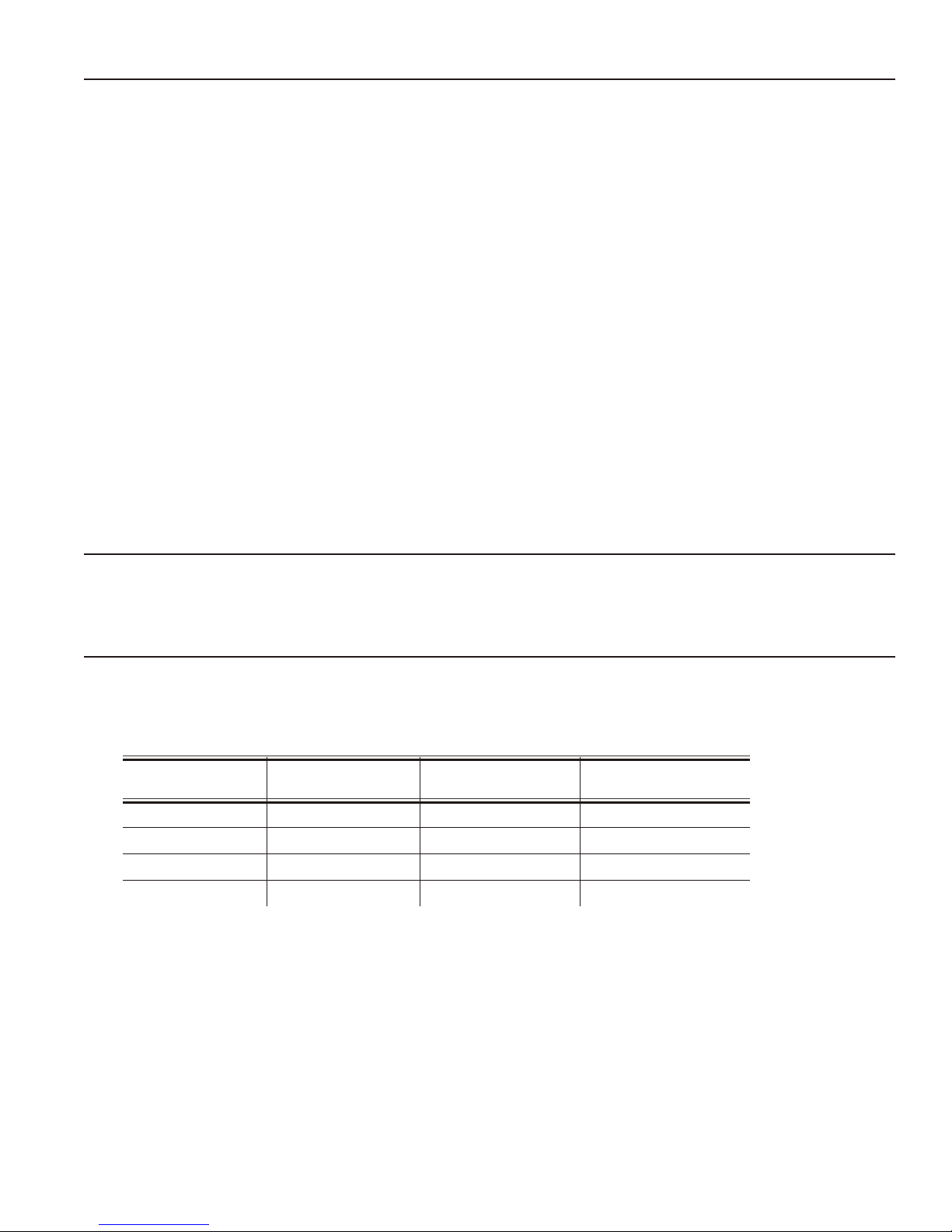
10. Type COPY SAMPLE.FMT COM1. The following 2 inch by
2 inch label prints.
1-2 GETTING STARTED
Page 11
Starting with a Design
Before you create a format packet, you must design your label. There are several steps to
designing a custom label:
1. Decide which fields should appear on your label. See “Determining Format Contents” for
more information.
2. Determine your label size. Labels are available from us in a wide variety of sizes. Your
application and the amount of data you need to print determines the supply size. Contact
your Sales Representative for more information.
3. Draw a rough sketch of your label. You may want to draw several variations to see what
works best. See “Drawing Rough Sketches” for more information.
4. Identify the field types that appear on your label. See “Considering Field Types” for more
information.
5. Decide which fonts you want to use. See “Considering Fonts” for more information.
6. Fill out your Format Worksheet. See “Using the Format Worksheet” for more information.
At this point, you are ready to use your format.
7. Create a format packet, based on how you filled out your worksheet. See Chapter 3,
“Defining Fields,” for more information.
Determining Format Contents
Before you lay out your format, answer these questions. How large is your supply, which fonts
do you want to use, do you want to include a bar code, and do you want to include graphics?
Determining the Print Area
The “bottom” is the edge that exits the printer first. The 0,0 point is at the bottom left corner of
the label. The print area varies, depending on the size of your supply. Below are the maximum
and minimum print areas. When designing formats, the following non-print zone is
recommended: 0.04 inches at the top and bottom of the label.
Unit of Measure Minimum Supply
Size (WxL)
English (1/100") 25 x 75 425 x 1000 400 x 1000
Metric (1/10mm) 63 x 191 1080 x 2540 1016 x 2540
Dots (1/203 dots) 51 x 152 864 x 2030 812 x 2030
Dots (1/300 dots) 75 x 225 1275 x 2700 1200 x 2700
The minimum label feed length for peel mode is 0.75 inches (19 mm).
Note: For exact print area measurements of your supply, see the supply layout grids in
Appendix D, "Format Design Tools."
Maximum Supply
Size (WxL)
Maximum Print
Area (WxL)
Use the following formulas to convert inches to dots and metric:
Dots = inches x 203 or (x 300 for 300 dpi)
Metric (1/10mm) = inches x 254
English (1/100 inch) = 100 x (dots/203) or (dots/300)
Dots = Metric (1/10 mm) x (799/1000) or (1181/1000)
300 dpi depends on your printer.
GETTING STARTED 1-3
Page 12
Drawing Rough Sketches
Supply Layout (dpi)
0.0
0.0
102
203
305
406
508 609
711
812
853
508
406
305
203
102
609
711
812
914
1015
1117
1218
1624
1523
1421
1320
203 300
0.0
750
600
450
300
150
900
1050
1200
1350
1500
1650
1800
2400
2250
2100
1950
0.0
150
300
450
600
750
900
1050
12001275
203
300
After you decide what information you want to print, sketch how you want
the information to appear on the label. Note any areas that are
preprinted on the label, such as a logo.
As soon as you know what information to include on the label, and you
have a rough sketch, you can use a supply layout grid to help you layout
and size your label. If you do not want to use a grid, go to “Considering
Field Types” to choose what information you want on your label.
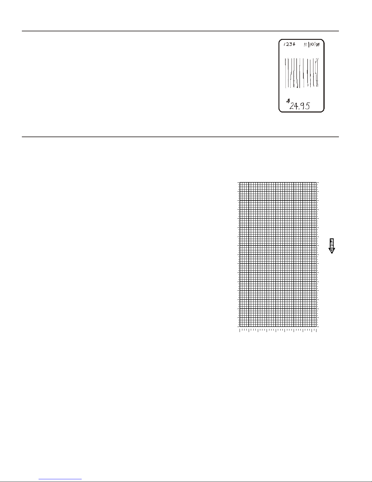
Using Supply Layout Grids
A supply layout grid contains measurement markers. These markers help you accurately
position information on your label. Decide whether you want to design formats using English,
Metric, or Dot measurements. Choose from the following grids:
¨ English
The English grid is measured in 1/100 inches.
¨ Metric
The Metric grid is measured in 1/10 millimeters (mm).
¨ Graphic
The printer uses dots to print images on a label. The
printhead has 203 dots per inch (dpi) or 300 dots per
inch.
Choose English or Metric units when designing formats
to use with different printers. English or Metric units
allow more direct use of formats on printers with different
density printheads.
If you want to use the supply layout grids, a copy of each
is in Appendix D, “Format Design Tools.”
1-4 GETTING STARTED
Page 13
Considering Field Types
After you select a supply size, the next step in designing a format is to decide what information
you want to print on the label. For example, you may want to print your company name, price of
an item, and a bar code that combines information from other places. Everything you want to
print falls into one of the following categories.
Field Type Description Examples
Text Contains letters, numbers, or symbols you want
to print.
Non-Printable
Text
Bar Code Used for printing bar codes that can be scanned. item or serial numbers, zip codes, information
Constant Text Prints fixed characters that print without
Line or Box Highlights or separates items. line marking out the regular price, border around
Graphic Contains a bitmap image or a compliance label
Holds data for use later, such as for merging into
another field. The printer does not print
non-printable text fields.
changing.
overlay.
item number, item description, department
number, price, date
city, state, and zip code to be included in a bar
code
you don’t want to have visible to customers
company name, company address
the supply
logos
All of the above field types except graphics are discussed in Chapter 3. See Chapter 5,
“Creating Graphics” for information on including graphics in your format.
Considering Fonts
When working with fonts, you have three considerations: font appearance, font size (scalable or
bitmapped), and font spacing (monospaced or proportional). See Appendix B, “Fonts,” for
samples of each font.
Interchanging Packets
You can use an MPCLII format that was designed for another MPCLII printer on a 9416 printer.
The format may appear smaller (fields will be shorter), because the 9416 printers use a 203 dpi
printhead. However, an optional 300 dpi printhead is available. If you use a 203 dpi format on a
300 dpi printer, it may appear almost 50 percent smaller.
Using the Format Worksheet
The Format Worksheet is divided into sections that list the field types. Each section has boxes
to fill in with parameters that define your format. A format worksheet is included in Appendix D,
“Format Design Tools.”
Filling in the Format Worksheet
Decide what type of field to use on your label.
1. Make a copy of the Format Worksheet.
2. Define the Format Header.
3. Define options as you require them. See Chapter 4, “Defining Field Options” for more
information.
GETTING STARTED 1-5
Page 14

1-6 GETTING STARTED
Page 15

CONFIGURING THE PRINTER 2
This chapter discusses how to
¨
set communication parameters.
¨
upload the printer’s configuration or font information.
¨
configure the printer using online configuration packets.
¨
use immediate commands to control the printer’s operation at any time.
Setting Communication Parameters
Use the following information if you are connecting to the printer’s 9-pin serial
port.
The communication parameters at the printer must match those at the host, or
you will not be able to communicate.
You can use the communication settings packet to set communication
parameters for your printer.
On MS-DOS computers, you can use the MODE command to set communication
values on your PC. For example
MODE COM1:9600,N,8,1
This command sets your host to these communication values:
¨ a baud rate of 9600
¨ no parity
¨ 8 bit word length
¨ 1 stop bit
CONFIGURING THE PRINTER 2-1
Page 16
Using Parallel Communications
If your printer supports parallel communications, the parallel port is Centronics® mode. The
communication settings are automatically configured for you. There are no operator settings
required.
We recommend waiting at least two seconds (or longer) when switching between the serial and
parallel ports to send data, because data may be lost. Be careful when using print spoolers,
because data transmission occurs in the background of the operating system. This makes data
transmission completion difficult to determine when switching between ports.
Using MPCLII Conventions
Here are some guidelines to follow when using MPCLII.
MPCLII Punctuation
Use the following symbols when creating MPCLII packets:
Character Decimal
{ (left bracket) 123 start of header
} (right bracket) 125 end of header
p (vertical bar) 124 field separator*
, (comma) 044 parameter separator
“ABC”
(quotation marks)
'comment'
(single quotation
marks)
* The field separator is the split vertical bar, which we are representing as p in this manual. The decimal value is 124. To enter
this character, use the Shift key plus the Split Vertical Bar key on your computer’s keyboard. Depending on your text editor, it
may appear as a solid vertical bar or as a split vertical bar.
Value
034 Quotation marks enclose character strings. Empty quotes (“”) identify null strings or unused
039 Grave accents enclose comments. Any data enclosed in grave accents is ignored. Do not
Description
fields.
embed comments within a quoted string. Grave accents are also used to reject mainframe
data.
Note: These MPCL characters are the default.
Standard Syntax Guidelines
When creating MPCLII packets:
¨ Begin each packet with a start of header ({).
¨ End each packet with an end of header (}).
¨ Define no more than1000 fields in a format. Each p indicates one field. However, options
are not counted as fields. The actual number of fields a format can have may be less,
because the number of fields is limited by the available memory.
¨ The field number (0 to 999) must be unique. We recommend starting at 1, instead of 0.
¨ Do not use a field number more than once per format.
¨ Define all fields in the order you want to image/print them. The printer does not print in field
number order.
¨ Separate all parameters with a Parameter Separator (,).
¨ End each field with a Field Separator ( p ).
¨ Enter all information in CAPITAL letters, except words or phrases within quotation marks.
2-2 CONFIGURING THE PRINTER
Page 17

¨ Include all parameters for a field unless documented as optional.
¨ Define non-printable text fields before the filed to which they apply.
¨ Define options immediately after the field to which they apply.
¨ Multiple options can be used with most fields. Options can be used in any combination
except as noted with each definition. Options are processed in the order they are received.
¨ Keep in mind that proportionally spaced fonts need wider fields than monospaced fonts. For
variable field data, use a letter “W” to determine the maximum field size.
¨ Do not place a new line (return) or any other non-printing character within a field definition.
However, a carriage return or line break after each p makes your formats easier to read.
T,1,20,V,30,30,1,1,1,1,B,C,0,0,0 p
T,2,10,V,50,30,1,1,1,1,B,C,0,0,0 p
¨ Spaces are ignored, except within character strings.
¨ Indenting options improves readability of your formats.
T,1,18,V,30,30,1,1,1,1,B,C,0,0,0 p
R,42,1 p
¨ Use a tilde (~) followed by a 3-digit ASCII code in a quoted string to send function codes or
extended characters or send the 8-bit ASCII code.
You can modify formats and fields with the optional entry method. See “Optional Entry Method”
in Chapter 6 for more information.
Using Online Configuration Packets
Use online configuration packets to change the printer’s settings. You can send an individual
configuration packet or a single packet containing all the configuration packets. Supply all
parameters for each packet. Leave the parameters blank that you do not need to change. For
example,
{ I,A,,,,1 p }
prints a slashed zero and uses the last sent online System Setup parameters.
Make a copy of the online configuration worksheet in Appendix D, “Format Design Tools,” and
save the original. Packets A-F are listed on the worksheet.
When you turn off the printer, all the information in the online configuration packets is saved and
used when the printer is turned back on. After you change printer configurations, you must
resend the format, batch, or graphic to the printer before the changes take effect.
Always include an I, im me di ately af ter the left bracket { and be fore the packet iden ti fier (A, B,
C, etc.). The I pa ram e ter iden ti fies the data stream as a con fig u ra tion packet.
Note: Include the I pa ram e ter with each packet if you are send ing them in di vid u ally. In clude it
only at the be gin ning of a data stream if you are send ing mul ti ple pack ets.
CONFIGURING THE PRINTER 2-3
Page 18

This is the syntax to use when you create online configuration packets:
Syntax
{ Start of Header
I, Con fig u ra tion Header
1 - 8 op tional re cords
A, pa ram e ter 1...pa ram e ter 5 p Sys tem Setup
B, pa ram e ter 1...pa ram e ter 5 p Sup ply Setup
C, pa ram e ter 1...pa ram e ter 5 p Print Con trol
D, pa ram e ter 1...pa ram e ter 3 p Mon e tary For mat ting
E, pa ram e ter 1...pa ram e ter 9 p Con trol Char ac ters
F, pa ram e ter 1...pa ram e ter 5 p Com mu ni ca tion Set tings
} End of Header
Syntax for single packet
{ Start of Header
I, Con fig u ra tion Header
A, pa ram e ter 1...pa ram e ter 5 Sys tem Setup
} End of Header
You can also add a configuration to RAM or specify units for supply, print, margin, and cut
positions. If you use the optional parameters with the I packet, any online configuration
packets following the split vertical bar ( p ) must specify distances using the selected units.
However, the test labels display the units in dots, even if you entered them in English or Metrics
units.
Syntax {header,ID#,action,device p }
1. header Constant I.
2. ID# ID. Use 0.
3. action Action. Options:
A Add configuration.
U Upload User Configuration.
4. device Storage Device. Use R (Volatile RAM).
Example {I,0,A,N,E p
C,0,25,0,0,0 p }
Adds a configuration to non-volatile RAM and specifies English units. It also uses the default
contrast, moves print 0.25 inches closer to the bottom of the supply and does not change the
margin adjustment, prints at the default print speed, and uses the default printhead width.
If you do not use the optional parameters, the syntax for the online configuration packets does
not change. For example,
{I,C,0,50,0,0,0 p }
uses the default contrast, moves print 50 dots (0.25) inches closer to the bottom of the supply
and does not change the margin adjustment, prints at the default print speed, and uses the
default printhead width.
2-4 CONFIGURING THE PRINTER
Page 19

Example {I,0,U,R p }
Uploads the printer configuration from volatile RAM and returns the following to the host.
A,0,0,0,0,1 p
B,2,0,0,0,0 p
C,0,0,0,0,0,0 p
D,1,0,2 p
E,"~123~044~034~124~125~126","","~013~010" p
F,3,1,0,0,1 p
The parameters for each packet (A-F) are displayed. See each packet description later in this
chapter for more information.
Configuration Syntax Guidelines
When creating a printer configuration packet:
¨ Follow the “Standard Syntax Guidelines” listed at the beginning of this chapter.
¨ The first character after the start of header ({) is the configuration header (I).
¨ Download multiple configuration packets within one packet or download a single
configuration packet.
¨ If you change any of the online configuration packets, resend the format packet to the
printer, so the configuration changes take effect.
¨ Include the first five ANSI codes, at a minimum, in the control characters packet.
¨ Send configuration packets once per session (each time the printer is turned off and then
back on), not with every format or batch packet.
¨ Make sure the communication settings at the host match those at the printer.
Making Print Adjustments
You can adjust where the printer prints on your supply by adjusting the supply, print, or margin
positions. However, keep in mind the following:
¨ Supply adjustments across the width of your supply, such as the margin position, are based
in dots. The printhead can be 203 or 300 dots per inch.
¨ Supply adjustments for the length of your supply, such as supply position or print adjustment,
are measured in ½03 of an inch, regardless of your printhead density.
CONFIGURING THE PRINTER 2-5
Page 20

Defining the System Setup Packet
Use the system setup packet (A) to select the power up mode, display language, print
separators between batches, print a “slashed zero,” and select the symbol set.
Syntax {I,A,powup_mode,lan guage,sep_on,slash_zero,sym bol_set p}
A1. A System Setup Packet
A2. powup_mode Online Mode. Enter 0.
A3. language Display Language. Enter 0.
A4. sep_on Batch Separators. Enter 0. The printer does not print batch separators.
A5. slash_zero Slash Zero. Enter 0. The printer does not print a zero with a slash through it.
A6. symbol_set Symbol Set. Options:
0 Internal (default)
1 ANSI
2 Code Page 437 (Latin U.S.)
3 Code Page 850 (Latin 1)
4 Code Page 1250 (Latin 2)
5 Code Page 1251 (Cyrillic)
6 Code Page 1252 (Latin 1)
7 Code Page 1253 (Greek)
8 Code Page 1254 (Turkish)
9 Code Page 1255 (Hebrew)
10 Code Page 1256 (Arabic)
11 Code Page 1257 (Baltic)
12 Code Page 1258 (Vietnamese)
13 Code Page 852 (Latin 2)
14 Code Page 855 (Russian)
15 Code Page 857 (IBM Turkish)
16 Code Page 860 (MS-DOS Portuguese)
19 Unicode
The Standard, Reduced, Bold, OCRA and HR fonts only support the Internal Symbol Set (0). The
CG Triumvirateä typefaces support only the ANSI and DOS Code 437 and 850 symbol sets. The
scalable font (font 50) does not support Code Page 1256 (Arabic). Code pages 852-860 and
1250-1258 are for downloaded TrueType fonts or the scalable font. Symbol Set 19 (Unicode)
requires a downloaded International TrueType font (stored on a memory card). TrueType fonts are
designed to be regionally specific; therefore, all code pages may not be supported in a given font.
See Appendix C, "Symbol Sets/Code Pages" for more information.
Example {I,A,0,0,0,1,0 p }
Powers up the printer in the online mode, displays prompts in English, does not print a
separator after each batch, prints zeros with slashes through them, and uses the internal symbol
set.
2-6 CONFIGURING THE PRINTER
Page 21

Defining the Supply Setup Packet
Use the supply setup packet (B) to select supply type, ribbon, feed mode, supply position, and
cut position.
Syntax {I,B,sup ply_type,rib bon,feed_mode,sup ply_posn,cut_posn p}
B1. B Supply Setup Packet
B2. supply_type Supply Type. Options:
0 Black mark supply
1 Die Cut/edge aperture supply (default)
2 Continuous (non-indexed) supply
Note: You must use continuous (non-indexed) supply in continuous mode. You may need to
adjust the print contrast (in the Print Control packet) based on the type of supply you are
using.
B3. ribbon Ribbon. The printer automatically senses if a ribbon is installed and switches to thermal transfer
mode. 0 is the default. Options:
0 Ribbon not installed (thermal direct)
1 Ribbon installed (thermal transfer)
Note: If “ribbon installed” is sent to the printer, but no ribbon is installed, an error occurs. If
“ribbon not installed” is sent to the printer, but a ribbon is installed, no error occurs.
B4. feed_mode Feed Mode. Options:
0 Continuous operation (default)
1 On-demand mode
B5. supply_posn Supply Position. Range: -300 to 300 in 1/203 inch. 0 is the default. Adjusts the machine to print
at the vertical 0,0 point on the supply. This adjustment accounts for mechanical tolerances from
machine to machine. The supply position adjustment only needs to be made on the initial machine
setup. Adjust the supply position if formats do not start at the 0,0 point on the supply. Increase the
supply position to move print up, decrease to move print down on the label. To verify the 0,0 point,
print a test label. See “Printing a Test Label” in Chapter 8 for more information.
You can not change the supply position while the printer is active. Changing the supply position
affects the print position. Once the supply position is set, use the print control packet to adjust the
print position.
B6. cut_posn Cut position. Range: -300 to 300 in 1/203 inch. Adjusts where the tag is cut. The printer adjusts
the cut position according to the black marks on the supply. You may need to adjust for your
supplies. Increase to move the cut up, decrease to move the cut down.
Example {I,B,0,0,1,10,50 p }
Indicates black mark and thermal direct stock has been loaded, causes the printer to operate in
on-demand mode, feeds the supply approximately .05 inches up before printing the format on
each label (10/203 inches), and feeds the supply .25 inches (50/203 inches) before cutting.
CONFIGURING THE PRINTER 2-7
Page 22

Defining the Print Control Packet
Use the print control packet (C) to set the contrast, print, and margin adjustment, print speed,
and printhead width.
Syntax {I,C,con trast,print_adj,mar gin_ad just,speed_adj,
ph_width p }
C1. C Print Control Packet
C2. contrast Print Contrast. Range: -390 to 156. 0 is the default. You may need to adjust this value depending
on the type of supplies you are using. To make the print darker, use increments of 13 (for example,
0, 13, 26, 39, 52, etc.). To make the print lighter, use increments of -129 (for example, -129, -258,
or -387). You need to use these incremental values to see a difference in the print contrast. For
example, values 1 to 13 produce the same result. This is true for values -1 to -130.
C3. print_adj Print adjustment (position). Range: -99 to 99 in 1/203 inch. 0 is the default. Adjusts where data
prints vertically on the supply. Increase the print position to move print up, decrease to move print
down.
C4. margin_adj Margin adjustment (position). Range: -99 to 99 in 1/203 inch. 0 is the default. Adjusts where data
prints horizontally on the supply. Increase the margin position to move print to the right, decrease
to move print to the left. Margin and print position are format adjustments. They do not effect the
supply position.
C5. speed_adj Print Speed in inches per second (ips). The only valid settings for 300 dpi are 20 and 30. Options:
0 This is the default and the printer prints at 3.0 ips.
20 Uses a print speed of 2.0 ips.
30 Uses a print speed of 3.0 ips
40 Uses a print speed of 4.0 ips (not for 300 dpi)
50 Uses a print speed of 5.0 ips (not for 300 dpi)
C6. ph_width Width of the printhead in dots. Use 0.
Example {I,C,0,-20,-10,0,0 p }
Uses the default contrast, moves print 0.1 inch closer to the bottom of the supply (20/203
inches) and .05 inch to the left on the supply (10/203 inches), the printer prints at the default
speed (3.0 ips), and uses the default printhead width.
2-8 CONFIGURING THE PRINTER
Page 23

Defining the Monetary Formatting Packet
The monetary formatting packet (D) selects the monetary symbols to print for a price field. Use
the monetary formatting packet to select primary and secondary monetary symbols, and
designate the number of digits to appear at the right of a decimal.
Syntax {I,D,cur_sym,sec ond ary,dec i mals p }
D1. D Monetary Formatting Packet
D2. cur_sym Currency Symbol. Options:
0 No symbol
1 USA ($, Dollar- default)
2 UK (£, Pound)
3 Japan (¥, Yen)
4 Germany (1, Deutsche Mark)
5 France (F, Franc)
6 Spain (P, Peseta)
7 Italy (L., Lira)
8 Sweden (Kr, Krona)
9 Finland (2, Markka)
10 Austria (6, Shilling)
11 India (Rs, Rupee)
12 Russian (3, Ruble)
13 Korean (4, Won)
14 Thai (5, Baht)
15 Chinese (¥, Yuan)
16 Euro-Dollar (c)
Note: To use these symbols, select the internal symbol set.
D3. secondary Secondary Sign. Secondary symbols only print if you designate at least one decimal place.
Options:
0 No secondary sign (default)
1 Print secondary sign
D4. decimals Number of digits to the right of the decimal. Options:
0 No digits
1 One digit
2 Two digits (default)
3 Three digits
Example {I,D,1,1,2 p }
Prints the dollar sign, uses a secondary symbol, and places two digits to the right of the
decimal.
CONFIGURING THE PRINTER 2-9
Page 24

Defining the Control Characters Packet
Use the control characters packet (E) to change the MPCLII control characters, enable and
disable the immediate commands, and change the default terminator character for job requests
and ENQ’s.
Changes take effect with the first character following the end of header character } of the
configuration packet. Each control character must be unique and cannot appear anywhere else
in your packet, except within quotation marks. You can customize the trailer characters to work
with your host.
Note: Wait two seconds for the new characters to take effect before sending packets using the
new characters.
Use the following syntax for the control characters packet. Notice all but the first parameter are
within quotation marks.
Syntax {I,E,"ANSI_cd","string1","string2" p }
E1. E Control Characters Packet
E2. “ANSI_cd” ~123 Start of header { (left bracket)
~044 Parameter , (comma)
separator
~034 Quoted strings “ (quotes)
~124 Field separator p (pipe sign)
~125 End of header } (right bracket)
~126 Data escape ~~ (double tilde)
character (optional)
def. ch. Immediate command character (optional).
Up to any 3 characters in the 0 to 255 decimal
range. The character must be defined before this
command can be used. The caret (~094) is
normally used.
Note: “ANSI_cd” includes seven separate parameters. The first five parameters are required.
The other parameters are optional.
E3. “string 1" Terminator for status requests and ENQ requests. Up to any 3 characters in the 0-255 decimal
range. The default is “013". Sending ”" disables this sequence.
E4. “string 2" Terminator for job requests and data uploads. Up to any 3 characters in the 0-255 decimal range.
The default is none. Sending “” disables this sequence.
After you change these parameters, all packets, including any future configuration packets, must
use the new control characters. We recommend using the tilde and ASCII character code
sequence when sending this packet multiple times. Also, set the packet delimiters to characters
within the 21 hex to 7E hex range.
You must send the control characters packet to enable the immediate commands. An immediate
command executes immediately, even if it is embedded within quotation marks, and all data
following the command in the string is ignored.
Example {I,E,"~123~063~034~124~125~126~094" p }
Changes the parameter separator character from , to ?. The other control characters remain
unchanged. It also enables the immediate commands by defining the ^ symbol as the command
identifier.
2-10 CONFIGURING THE PRINTER
Page 25

Resetting Control Characters
You can change the characters in the previous example back to their original settings by
downloading this packet:
{I?E?"~123~044~034~124~125~126~094" p }
Notice that the parameter separator is ? in this packet. This is the parameter separator that was
set before this packet. Once the packet is received by the printer, the new parameter separator
(a comma, in this case) is valid.
Be careful when using this feature. If you forget what the control characters were changed to,
print a test label. (The test label lists the current control characters.) See “Printing a Test
Label,” in Chapter 8 for more information.
Using Immediate Commands
Immediate commands effect printer operation as soon as the printer receives them, even if they
are included within a packet or used inside quotation marks.
You can use immediate commands to change immediate command or status polling control
characters, reset the printer, or cancel and repeat batches.
Enabling Immediate Commands
When the printer is first turned on, these commands are not available. To use these commands,
you must first send the control characters packet and define the immediate command control
character. The immediate command control character is saved when you turn off the printer.
Once the immediate command control character is defined, the immediate commands are
enabled.
Sending Immediate Commands
Immediate commands consist of a three- or four-character sequence you can send in a packet
or embed in your application. Each command must be sent separately.
Syntax control character_immediate command
The printer can accept only one immediate command at a time. Sending a command before the
previous one is completed can result in an error.
Example ^CB
Immediately cancels the batch currently printing unless an error exists on the printer. This
example assumes that the defined immediate command control character is the caret (^).
The table represents the defined immediate command control character as ^ and the defined
status polling control character as d. You may define these characters to suit your needs.
CONFIGURING THE PRINTER 2-11
Page 26

Command Parameter
^CA
^CB
^DD or ^DCd
^EA
^ER
^FD
^ID or ^ICd
^MC
^MD
^MI
^MM
^MP
^MR
^MV
^PR
^RB
^RS
^TP
Cancels all the batches in the queue unless an error exists on the printer.
Cancels only the current batch being printed unless an error exists.
Disables the MPCL data escape character (the tilde) and inhibits MPCL from acting on ANY data escape sequence
from the host. Sets the MPCL data escape character to the ASCII value given by the d parameter. The value can
be any ASCII character.
Aborts an error condition. May need to be sent multiple times. Use ^RB to reprint batch.
CAUTION: This command causes the current batch to stop and the condition that caused the error to remain
uncorrected.
Resets the error. Normal operation resumes.
Feeds a label when printer is idle. Simulates the operation of pressing FEED and dispenses the next label if the
printer is in the on-demand mode.
Note: Printer ignores this command if printing.
Disables the Immediate Command feature by turning off the Immediate Command escape character. Sets the
Immediate Command escape character to the ASCII value given by the d parameter. The value can be any ASCII
character. Use ^IE to enable immediate commands.
Returns the customer ID or RPQ version to the host. (00 to 99)
Returns the printhead dot density to the host. 00 = 203 dpi 01 = 300 dpi
Returns the customer ID or RPQ revision level to the host. (00 to 99)
Returns the model number to the host. 41 = 9416
Returns the prototype number to the host. (00 to 99)
Returns the revision number to the host. (00 to 99)
Returns the version number to the host. (00 to 99)
Resets the printer. This command takes five seconds to complete and then the printer is ready to receive data. It
has the same effect as turning off and then turning on the printer. Note: Command should be used only when the
printer is not printing.
Repeats the last printed batch, printing the same number of labels as specified in the original batch. This command
does not work if using batch separators.
Note: Printer ignores this command if printing.
Resynchronizes supply when supply roll is changed.
Note: Printer ignores this command if printing.
Prints a test label.
Note: Printer ignores this command if printing.
Note: To use the immediate command control character or the status polling character within
your data, use the tilde sequence.
2-12 CONFIGURING THE PRINTER
Page 27

Defining the Communication Settings Packet
Use the communication settings packet (F) to set the baud rate, word length, stop bits, parity,
and flow control for serial communications. To set parallel communications, see “Using Parallel
Communications.”
Changing the communication settings takes approximately two seconds. Communications sent
during this interval will be lost. Make sure the host communication values match the values on
the printer and the host is capable of communicating at the speed you select for the printer.
Do not add any characters, such as a carriage return/line feed, in your communication settings
packet or communications errors may occur.
Syntax {I,F,baud,word_length,stop_bits,par ity,
flow_con trol p }
F1. F Communication Settings Packet
F2. baud Baud Rate. Options:
0 1200 3 9600 (default)
1 2400 4 19200
2 4800 5 38400
F3. word_length Word Length. Options:
0 7-bit word length (odd or even parity only)
1 8-bit word length (default)
F4. stop_bits Stop Bits. Options:
0 1-stop bit (default)
1 2-stop bits
F5. parity Parity. Options:
0 None (default)
1 ODD parity
2 EVEN parity
F6. flow_control Flow Control. Options:
0 None 2 (CTS)
1 DTR (default) 3 XON/XOFF
Note: If you use the DOS COPY command to download your formats, set “Flow Control” to DTR
(not XON/XOFF).
Example {I,F,3,1,0,0,1 p }
Uses 9600 baud, an 8-bit word length, one stop bit, no parity, and the DTR mode.
CONFIGURING THE PRINTER 2-13
Page 28

Clearing Packets from Memory
You may want to remove packets from the printer to increase memory storage capacity or if the
formats/fonts are no longer needed. In some cases, turning the printer off may clear the
packets from memory. If not, send a format clear packet.
Syntax {header,packet#,action,device p }
1. header Identifies the packet. Options:
A Check Digit Scheme
F Format
G Graphic
W Font
2. packet# Identification number of the packet to clear (1 to 999) or font number
(0 to 9999). 0 is for all fonts.
3. action Action. Enter C to clear the packet.
4. device Storage device. Use R (Volatile RAM).
Example {F,1,C,R p }
Clears Format #1 from volatile RAM.
Using the Font Packet
You can use a font packet to add or clear downloaded fonts from memory, upload your font
buffer, or upload the cell size information for a particular font. The font packet is useful when
you are downloading fonts. If you are using downloaded fonts, the font number and the number
of bytes each downloaded font uses is listed.
This packet does not list the number of bytes the standard printer fonts use.
Use the MONARCH® MPCL Toolbox Font Utility (available on our Web site) to create the font
header and data. Refer to the online help for more information.
Syntax {W,font#,action,device,data_length,data_record p }
W1. W Writable Font Header.
W2. font# The font identifier from 0 to 32000.
0 is for all fonts. 1 to 5 digits is the font number.
Example: 3 is the standard printer font, Bold.
W3. action Action. Options:
A Adds the specified font.
C Clears all or specified fonts, except ones in flash.
H Uploads font size information.
M Uploads font memory usage information.
W4. device Device. Options:
M Memory card - this is optional for the 9416 and 9416XL printers.
R Volatile RAM
Z All devices (use for upload).
W5. data_length
(optional)
The length of the font data. The range is 68 to 16384.
If you are creating fonts, you need to have font data included with this packet.
W6. data_
record
(optional)
2-14 CONFIGURING THE PRINTER
Multiple data records define the font. The first character is either an
H (hex) or an R (run-length), referring to the algorithm. The rest of the record is up to 2710
characters of font data in double quotes. Separate the algorthm and the data with a comma, and
end the record with p .
Page 29

Example {W,0,M,R p }
Selects all fonts and checks the memory usage in RAM. The printer returns the following to the
host:
{W,0,M,R p
Number of bytes free, Number of bytes used p }
Example {W,0,H,Z p }
Selects all fonts and uploads the font size information for any downloaded fonts.
The printer returns the following to the host:
{W,0,H,Z p
0,1,0,"Standard",0,0,0,14,22,14,22,3 p
0,1,437,"Standard",0,0,0,21,33,21,33,5,1 p
0,2,0,"Reduced",0,0,0,10,21,10,21,2,1 p
0,2,437,"Reduced",0,0,0,10,21,10,21,2,1 p
0,3,0,"Bold",0,0,0,36,51,36,51,5,1 p
0,3,437,"Bold",0,0,0,36,51,36,51,5,1 p
0,4,0,"OCRA",0,0,0,19,36,19,36,5,1 p
Font Name
Spacing
0,4,437,"OCRA",0,0,0,19,36,19,36,5,1 p
0,5,0,"HR1",0,0,0,18,30,18,30,3,1 p
0,5,437,"HR1",0,0,0,18,30,18,30,3,1 p
Baseline
Font Style
0,6,0,"HR2",0,0,0,26,24,26,24,2,1 p
0,6,437,"HR2",0,0,0,26,24,26,24,2,1 p
Cell Width
0,10,0,"CGTriBd9",1,0,7,25,31,10,15,0 p
0,10,1,"CGTriBd9",1,0,7,25,31,10,15,0 p
0,10,437,"CGTriBd9",1,0,7,25,31,10,15,0 p
Cell Height
0,10,850,"CGTriBd9",1,0,7,25,31,10,15,0 p
0,11,0,"CGTriumv6",1,0,5,17,21,5,10,0 p
0,11,1,"CGTriumv6",1,0,5,17,21,5,10,0 p
0,11,437,"CGTriumv6",1,0,5,17,21,5,10,0 p
Inter-Character Gap
Nominal Height
0,11,850,"CGTriumv6",1,0,5,17,21,5,10,0 p
0,15,0,"CGTriumv7",1,0,7,21,28,9,14,0 p
Nominal Width
0,15,1,"CGTriumv7",1,0,7,21,28,9,14,0 p
0,15,437,"CGTriumv7",1,0,7,22,28,9,14,0 p
0,15,850,"CGTriumv7",1,0,7,22,28,9,14,0 p
Typ e
0,16,0,"CGTriumv9",1,0,8,28,35,12,18,0 p
0,16,1,"CGTriumv9",1,0,8,28,35,12,18,0 p
Printhead Density
0,16,437,"CGTriumv9",1,0,8,29,35,12,18,0 p
0,16,850,"CGTriumv9",1,0,8,29,35,12,18,0 p
0,17,0,"CGTriumv11",1,0,9,31,40,13,22,0 p
Symbol Set
0,17,1,"CGTriumv11",1,0,9,31,40,13,22,0 p
0,17,437,"CGTriumv11",1,0,9,33,40,13,22,0 p
0,17,850,"CGTriumv11",1,0,9,33,40,13,22,0 p
0,18,0,"CGTriumv15",1,0,13,47,59,20,31,0 p
0,18,1,"CGTriumv15",1,0,13,47,59,20,31,0 p
0,18,437,"CGTriumv15",1,0,13,49,59,20,31,0 p
0,18,850,"CGTriumv15",1,0,13,49,59,20,31,0 p
0,50,0,"EffSwissBold",1,1,92248 p }
* The CG Triumvirateä typefaces are trademarks of Monotype Imaging, Inc.
CONFIGURING THE PRINTER 2-15
Page 30

Spacing Monospaced (0) or proportional (1).
Type Bitmapped (0) or scalable (1).
Baseline Bottom of the font.
Cell Width Horizontal number of dots to contain the widest character.
Cell Height Vertical number of dots to contain the tallest character.
Nominal Width Average width for lower-case letters.
Nominal Height Average height for lower-case letters.
Inter-Character
Default spacing between characters in monospaced fonts.
Gap
Printhead Density Shows that a 203 (0) dpi or 300 dpi (1) printhead is used. The scalable font
(font 50) does not report a value for printhead density.
Uploading Format Header Information
You can upload format header information from the formats in memory to check the supply
length and width for each format.
Syntax {header,format#,action,device p }
F1. header Format Header
F2. format# Format number from 0 to 999. 0 is for all formats in memory.
F3. action Action. Options:
A Adds the specified format
C Clears the specified format
H Uploads format header information
F4. device Device. Options:
R Volatile RAM
Z All devices (use for upload)
Example {F,0,H,Z p }
Selects all formats in memory and returns the following:
Example {F,0,H,Z p
Fmt_1,406,406 p
Fmt_10,324,406 p
Fmt_15,812,812 p
Fmt_20,305,609 p
Fmt_25,1218,406 p }
Displays the format number, supply length and supply width (in dots) for each format in memory.
Example {F,1,H,Z p }
Selects format1 and returns the following to the host:
{F,1,H,Z p
Fmt_1,406,406 p }
Displays the supply length and supply width (in dots) for format1.
2-16 CONFIGURING THE PRINTER
Page 31

DEFINING FIELDS 3
This chapter provides a reference for defining
¨
the format header
¨
text and constant text
¨
non-printable text fields
¨
bar code fields
¨
line and box fields.
DEFINING FIELDS 3-1
Page 32

Defining the Format Header
A Format Header begins a format file.
Syntax {F,format#,action,device,measure,length, width,"name" p
F1. F Format Header.
F2. format# Unique number from 1 to 999 to identify the format.
F3. action Action. Enter A to add the format to the printer.
F4. device Format storage device. Options:
M Memory Card (only supported by the 9416XL printer with an
optional memory card).
R Volatile RAM
F5. measure Unit of measure. Options:
E English, measured in 1/100 inches
M Metric, measured in 1/10 mm
G Graphic, measured in dots
F6. length Supply length in selected units. Measure supply from the leading edge of one label to the leading
edge of the next label.
English 25 - 1000
Metric 63 - 2540
203 Dots 51 - 2030
300 Dots 75 - 2700
In peel mode, the minimum label length is 0.75 inches (19 mm). For 300 dpi, the maximum label
length is 9.0 inches (229 mm).
Make sure your format length matches the actual label size exactly for correct printer performance.
This is especially true for shorter feed length supply and formats. If an error occurs, recalibrate the
supplies in the printer. Refer to your Quick Reference for more information.
F7. width Supply width, from left to right, in selected units.
English 75 - 400
Metric 191 - 1016
203 Dots 152 - 812
300 Dots 225 - 1200
F8. “name” Format name (optional), 0 to 8 characters, enclose within quotation marks.
Example {F,1,A,R,E,300,100,"TEXTILES" p
Adds Format 1 (“TEXTILES”) to the printer. It uses a three inch long by two inch wide label.
3-2 DEFINING FIELDS
Page 33
Defining Text Fields
Create a separate definition for each text field. If text falls on two lines, each line of text
requires a separate definition.
Syntax T,field#,# of char,fix/var,row,column, gap,font,hgt mag,wid mag,
color,alignment, char rot,field rot,sym set p
T1. T Text Field.
T2. field# Unique number from 1 to 999 to identify this field.
T3. # of char Maximum number of printed characters (0 to 2710) in the field.
T4. fix/var Fixed or variable length field. Options:
F Fixed length
V Variable length
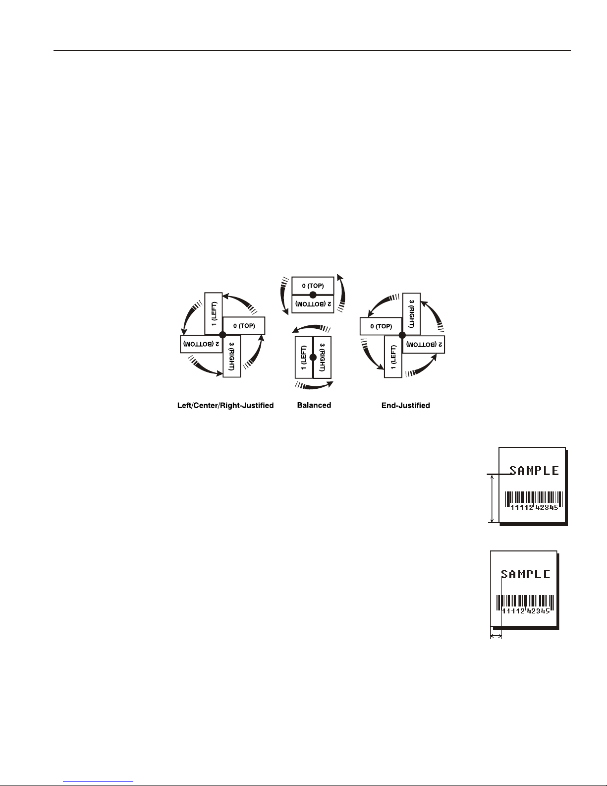
T5. row For monospaced fonts, distance from bottom of print area to the pivot point. The pivot point varies
depending on how text is justified.
For proportionally spaced fonts, distance from bottom of print area to baseline
of characters in field.
English 0 - 999
Metric 0 - 2539
203 Dots 0 - 2029
300 Dots 0 - 2699
T6. column Distance from the left edge of the print area to the pivot point to find the
column location.
English 0 - 399
Metric 0 - 1015
203 Dots 0 - 811
300 Dots 0 - 1199
DEFINING FIELDS 3-3
Page 34

T7. gap Number of dots between characters 203 dpi (or 300 dpi). Range: 0 to 99.
Note: For monospaced fonts, the additional spacing is added to the existing inter-character gap.
This is also true for proportionally spaced fonts, but remember that the inter-character gap
varies with character combinations.
Any number other than 0 or the default number affects your field width. Default spacing:
Standard 3 dots
Reduced 1 dot
Bold 3 dots
OCRA-like 3 dots
HR1 3 dots
HR2 2 dots
CG Triumvirateä
Typeface Bold varies with each letter
CG Triumvirateä Typeface varies with each letter
EFF Swiss Bold varies with each letter
HR1 and HR2 are only used with the UPC bar code family and must be numeric.
T8. font Style of font. Options:
1 Standard 10 CG Triumvirateä Typeface Bold
2 Reduced 11 CG Triumvirateä Typeface
3 Bold 15 7 pt. CG Triumvirateä Typeface
4 OCRA-like 16 9 pt. CG Triumvirateä Typeface
5 HR1 17 11 pt. CG Triumvirateä Typeface
6 HR2 18 15 pt. CG Triumvirateä Typeface
50 EFF Swiss Bold (scalable)
Or a valid downloaded font selector number.
Fonts 5 and 6 are only for numeric data.
Fonts 15 - 18 are only for 300 dpi and do not support Code pages 0, 1, 437, and 850.
The CG Triumvirateä typefaces support only the ANSI and DOS Code Page 437 and 850 Symbol
Sets. See Appendix C, "Symbol Sets/Code Pages" for more information.
T9. hgt mag Height magnifier, 1 to 7 times (4 to 255 points for the scalable font - font 50 or downloaded
TrueType fonts). Use a magnifier of 1 with proportionally spaced fonts, because characters lose
smoothness at higher magnifications. See Appendix B, “Fonts,” for more information about fonts.
T10. wid mag Width magnifier, 1 to 7 times (4 to 255 points for the scalable font - font 50 or downloaded TrueType
fonts). Proportionally spaced fonts do not have a set width. To estimate the size of your field, use
the letter “W” for the widest field or an “L” for an average width field. Find your selected font and
the desired width in Appendix B, “Fonts.”
Note: To use large point sizes (greater than 60 point), you must reconfigure memory and
increase the size of the scalable (vector) fonts buffer.
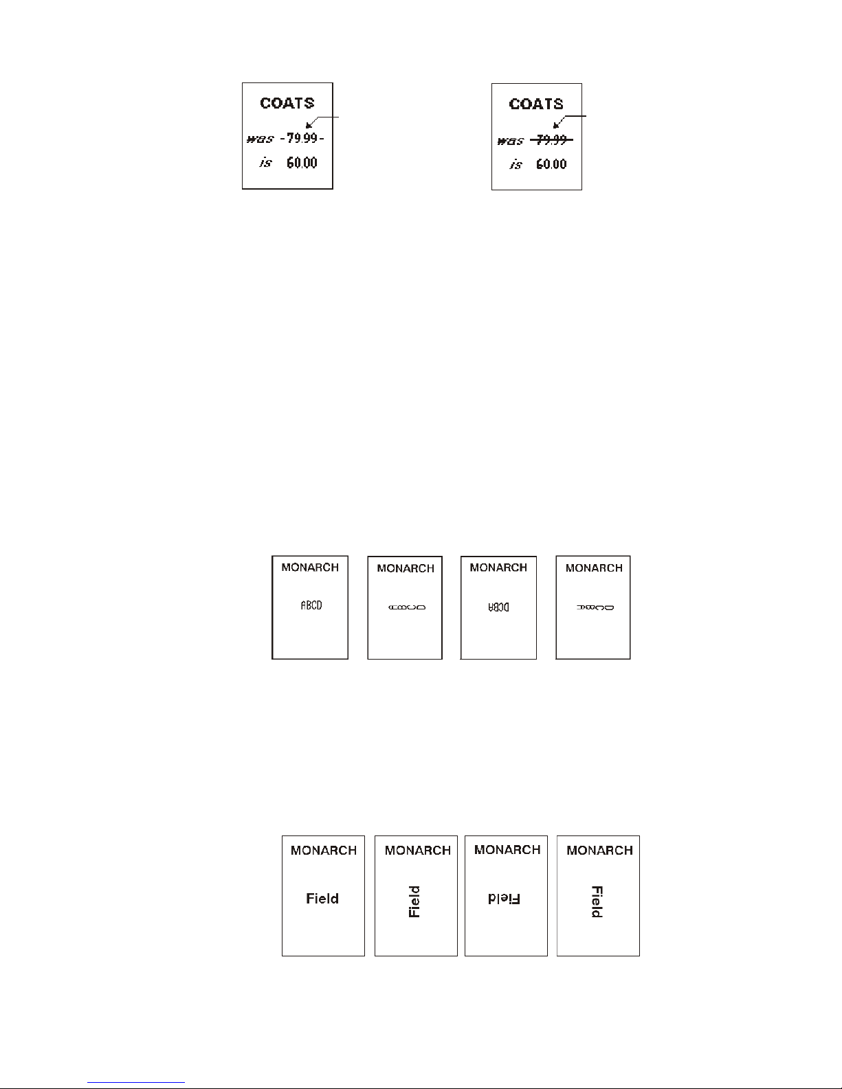
T11. color There are two types of field color overlay attributes:
Transparent The overlay field (text or constant text) does not block out
(or “erase”) existing fields.
Opaque The overlay field blocks out (or “erases”) existing fields.
Options for standard printer fonts:
B Opaque, Normal, Black, Normal
D/R/W Opaque, Normal, White, Normal
O Transparent, Normal, Black, Normal
Options for scalable fonts:
A/N Opaque, Normal, Black, Bold
B/O Opaque, Normal, Black, Normal
E/S Opaque, Italics, Black, Bold
F/T Opaque, Italics, Black, Normal
3-4 DEFINING FIELDS
Page 35
Line field
blocked out by
opaque field
using attribute B
Line field not
blocked out by
transparent field
using attribute O
Note:
Field placement in the packet is an important consideration when using field color attributes. If a
line field is defined before the overlay (text or constant text) field, the line field is blocked out by the
overlay field, depending on the overlay field’s color attribute. If a line field is defined after the
overlay field, the line field is not blocked out by the overlay field, regardless of the overlay field’s
color attribute.
T12. alignment Options:
T13. char rot Character rotation. The field or supply does not rotate, only the characters do. Options:
Solid black print should not exceed 25% on a given square inch of the label, or the
printhead life may be decreased.
L Align on left side of field.
C Center text within field (monospaced fonts only)
R Align on right side of field (monospaced fonts only)
B Align at midpoint of field
E Align at endpoint of the field
Use L, B, or E for any font.
0 Top of character points to top of field
1 Top of character points to left of field
2 Top of character points to bottom of field
3 Top of character points to right of field
Note: Font 50 and downloaded TrueType fonts do not support character rotation.
T14. field rot Field rotation. Field rotation rotates the whole field, not just the characters. Rotation is affected by
the pivot point, which varies depending on how text is justified. Lower left corner of field is the pivot
point. Options:
0 Top of field points to top of supply
1 Top of field points to left of supply
2 Top of field points to bottom of supply
3 Top of field points to right of supply
DEFINING FIELDS 3-5
Page 36

T15. sym set Symbol set. Use 0 for the Internal Symbol Set. For scalable or TrueTypeâ fonts, use:
1 ANSI Symbol Set
102 Unicode (user input) for particular mapping
437 DOS Code Page 437 (Domestic)
850 DOS Code Page 850 (International)
852 DOS Code Page 852 (Latin 2)
855 DOS Code Page 855 (Russian)
857 DOS Code Page 857 (IBM Turkish)
860 DOS Code Page 860 (MS-DOS Portuguese)
1250 DOS Code Page 1250 (Latin 2)
1251 DOS Code Page 1251 (Cyrilic)
1252 DOS Code Page 1252 (Latin 1)
1253 DOS Code Page 1253 (Greek)
1254 DOS Code Page 1254 (Turkish)
1255 DOS Code Page 1255 (Hebrew)
1256 DOS Code Page 1256 (Arabic)
1257 DOS Code Page 1257 (Baltic)
1258 DOS Code Page 1258 (Vietnamese)
The Standard, Reduced, Bold, OCRA and HR fonts only support the Internal Symbol Set (0). The
CG Triumvirateä typefaces support only the ANSI and DOS Code 437 and 850 symbol sets. The
scalable font (font 50) does not support Code Page 1256 (Arabic). Code pages 852-860 and
1250-1258 are for downloaded TrueType fonts or the scalable font. Symbol Set 102 (Unicode)
requires a downloaded International TrueType font (stored on a memory card). TrueType fonts are
designed to be regionally specific; therefore, all code pages may not be supported in a given font.
See Appendix C, "Symbol Sets/Code Pages" for more information.
Example T,2,10,V,50,80,0,1,1,1,B,C,0,0,0 p
Defines a text field (field #2) with a variable length of up to 10 characters. The field begins at
row 50, column 80. There is no additional gap between characters, and the Standard font is
used without any additional magnification. The printing is black on white and centered. No field
or character rotation is used. The internal symbol set is used.
Defining Bar Code Fields
Each bar code field requires a separate definition.
Syntax B,field#,# of char,fix/var,row,column, font,density,height,text,
alignment,field rot p
B1. B Bar Code Field.
B2. field# Unique number from 1 to 999 to identify this field.
B3. # of char Maximum number of characters. If the bar code uses a check digit, allow an extra character for the
check digit. The actual maximum number of characters is limited by the size of the label and bar
code density. Range: 0 to 2710.
For Quick Response bar codes, this number includes header information. The maximum depends
on the type of characters entered for the batch data and differs for the two models of the bar code.
Data Type Model 1 Model 2
Numeric Data 1167 2710
Alphanumeric data 707 2710
8-byte data 486 2710
Kanji data 299 1817
Note: The maximum number of characters depends on the selected level of error correction. As
you increase the error correction level, the maximum number of characters decreases.
3-6 DEFINING FIELDS
Page 37

B4. fix/var Fixed (F) or variable (V) length field.
Bar Code Number of Characters Fixed or Variable
UPCA
UPCA+2
UPCA+5
UPCA+Price CD
UPCE
UPCE+2
UPCE+5
EAN8
EAN8+2
EAN8+5
EAN13
EAN13+2
EAN13+5
EAN13+Price CD
POSTNET
Interleaved 2 of 5 or Interleaved
I 2 of 5 with Barrier Bar
Code 39 (w/ or w/o CD) or MOD43
Codabar (NW7)
Code 128
Code 16K
Code 93
MSI
PDF 417
Maxicode*
Data Matrix*
Quick Response*
0 to 93 (alphanumeric)
0 to 128 (numeric)
0 to 2335 (alphanumeric)
0 to 2710 (numeric)
1167 - 2710 (numeric)
707 - 2710 (alphanumeric)
12 F
14 F
17 F
12 F
7 F
9 F
12 F
8 F
10 F
13 F
13 F
15 F
18 F
13 F
9 or 11 F
0 - 2710 F or V
0 - 2710 F or V
0 - 2710 F or V
0 - 2710 F or V
0 - 2710 V
0 - 2710 V
0 - 14 F or V
0 - 2710 F or V
F or V
V
V
* For more information about MaxiCode, Data Matrix, and Quick Response, see Appendix A, “Samples.”
DEFINING FIELDS 3-7
Page 38
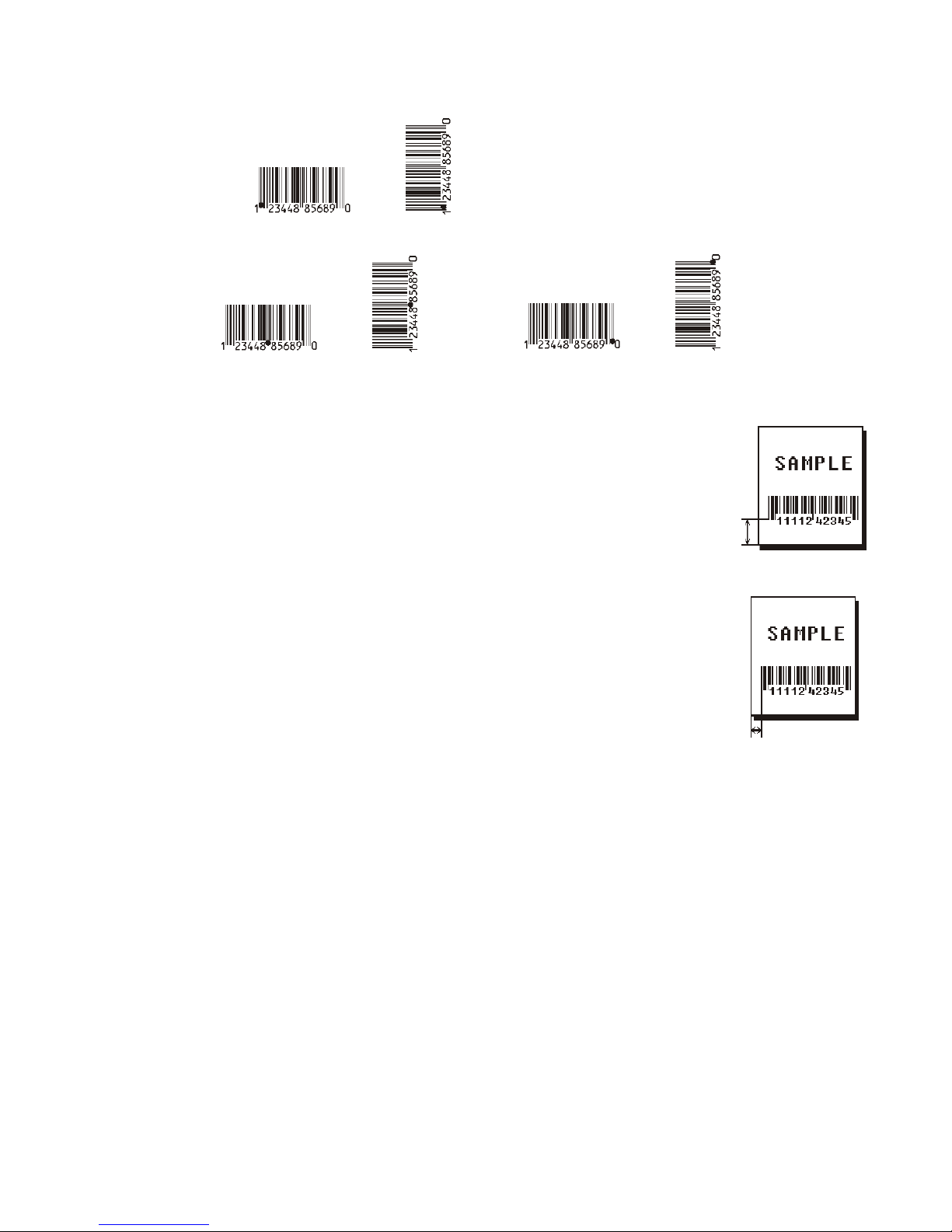
B5. row Distance from the bottom of the print area to the pivot point of the field. The pivot point varies,
depending on how the field is justified. Pivot points:
Left/Center/Right-Justified Fields
Balanced Fields
Remember to include text or numbers that may appear with the bar code for
the row measurement.
English 0 - 999
Metric 0 - 2539
203 Dots 0 - 2029
300 Dots 0 - 2699
B6. column Distance from the lower left edge of the print area to the pivot point.
English 0 - 399
Metric 0 - 1015
203 Dots 0 - 811
300 Dots 0 - 1199
Allow a minimum of 1/10 inch between the scan edge of bar code and label
edges or other data.
B7. font Bar code. Options:
1 UPCA 21 LAC
2 UPCE 22 POSTNET
3 Interleaved 2 of 5 23 Code 93
4 Code 39 (no check digit) 31 Code 16K
5 Codabar 32 PDF417
6 EAN8 33 MaxiCode
7 EAN13 35 Data Matrix (ECC-200)
8 Code 128 36 Quick Response
9 MSI 40 Code 39 (MOD 43 check digit)
10 UPCA +2 41 UPCA & Price CD
11 UPCA +5 44 EAN13 & Price CD
12 UPCE +2 50 Interleaved 2 of 5 with Barrier Bar
13 UPCE +5
14 EAN8 +2
15 EAN8 +5
16 EAN13 +2
17 EAN13 +5
End-Justified Fields
B8. density Bar code density. Use 0 for Quick Response bar codes. Use the following table for the other bar
codes.
3-8 DEFINING FIELDS
Page 39

203 DPI Bar Code Densities
Bar Code
Type
UPCA +2/+5
Price CD
UPCE
+2/+5
EAN8
+2/+5
EAN13+2/+5
Price CD
Interleaved
2 of 5
or I2of5
with Barrier
Bar
(Code 39 or
MOD43
(Extended
Code 39)
Codabar
(NW7)
Code 128
or
Code 16K
Density
Selector
2
4
2
4
2
4
2
4
1
2
3
4
5
6
7
8
9
10
11
12
13
1
2
3
4
6
7
11
12
20
2
3
4
5
7
8
9
4
6
8
20
Density
(% or cpi)
76%
114%
76%
114%
76%
114%
76%
114%
1.1
2.1
3.2
4.2
5.6
6.3
7.5
8.8
9.6
11.2
11.0
12.7
14.5
1.4
1.7
3.5
4.2
6.3
7.0
3.9
12.7
3.0
2.1
3.0
4.6
5.1
8.4
9.2
10.1
3.5/7.0
4.4/8.7
5.8/11.7
8.7/11.5
Narrow
Element
(dots/mils)
2/9.9
3/14.8
2/9.9
3/14.8
2/9.9
3/14.8
2/9.9
3/14.8
21/103.4
12/59.1
7/34.5
6/29.6
4/19.7
4/19.7
3/14.8
3/14.8
3/14.8
2/9.9
2/9.9
2/9.9
2/9.9
10/49.3
8/39.4
4/19.7
3/14.8
2/9.9
2/9.9
4/19.7
¼.9
5/24.6
8/39.4
6/29.6
4/19.7
4/19.7
2/9.9
2/9.9
2/9.9
5/24.6
4/19.7
3/14.8
2/9.9
Narrow to
Wide Ratio
N/A 11 or 12
N/A 6 or 7
N/A 7 or 8
N/A 12 or 13
1:3.0
1:2.5
1:3.0
1:2.5
1:3.0
1:2.5
1:3.0
1:2.3
1:2.0
1:3.0
1:3.0
1:2.5
1:2.0
1:2.5
1:2.5
1:2.5
1:3.0
1:3.0
1:2.5
1:2.0
1:3.0
1:2.2
1:3.0
1:2.5
1:2.5
1:2.0
1:3.0
1:2.5
1:2.0
N/A 0 to 2710 8 00H to 7FH
Data
Length
14/17
9/12
10/13
15/18
0 to 2710 8 0 to 9
0 to 2710 8 SPACE
0 to 26 8 $+-./
Appearance
Codes
Available
1, 5, 6, 7 or 8 0 to 9
1, 5, 6, 7 or 8 0 to 9
1, 5, 6,7 or 8 0 to 9
1, 5, 6,7 or 8 0 to 9
Char
$%*+-./
0 to 9
A to Z
0 to 9
a to d
Set
Note: The start (*) and stop (+) characters are automatically added for
Code 39. Code 39, density 12, produces a one-dot narrow bar. This
density is intended for special U.S.P.S. ACT-tag applications only.
DEFINING FIELDS 3-9
Page 40
203 DPI Bar Code Densities
Bar Code
Type
CODE 93 3
MSI 4
POSTNET 0 (fixed at
MaxiCode 7 N/A N/A N/A 99 8 00H to
Bar Code
Type
PDF417 1
Density
Selector
4
5
7
10
5
7
4.3 cpi)
Density
Selector
2
3
4
5
6
7
8
9
Density
(% or cpi)
3.7
4.5
5.6
7.5
11.2
4.2
5.6
7.2
24/118.2 10/49.3 4/19.7 (5
Element
Width
(dot/mils)
2/9.8
2/9.8
2/9.8
3/14.8
3/14.8
3/14.8
4/19.7
4/19.7
4/19.7
Narrow
Element
(dots/mils)
6/29.6
5/24.6
4/19.7
3/14.8
2/9.9
4/19.7
3/14.8
2/9.9
Row Height
(dots/mils)
2/9.8
4/19.7
6/29.6
3/14.8
6/29.6
9/44.3
4/19.7
8/39.4
12/59.1
Narrow to
Wide Ratio
N/A 0 to 2710 8 00H to
1:2.0
1:2.0
1:2.5
dot gap)
Aspect
Ratio
1:1
1:2
1:3
1:1
1:2
1:3
1:1
1:2
1:3
Data
Length
0 to 14 8 0 to 9
0,5,6,9 or118 0 to 9
Data
Length
0 to 2709 8 00H to
Appearance
Codes
Available
Appearance
Codes
Available
Char Set
7FH
FFH
Char Set
FFH
203/300 DPI Bar Code Densities
Bar Code Type Density
Quick Response
(QR Code) Models 1 and 2
Note: Values in bold indicate the default.
Selector
0
Data Length
Model 1: 0 - 1167 Numeric; 0 - 707 Alphanumeric; 0 - 486 (8-bit);
0 - 299 (Kanji)
Model 2: 0 - 2710 Numeric, Alphanumeric and 8-bit; 0 - 1817 Kanji
3-10 DEFINING FIELDS
Page 41
203/300 DPI Bar Code Densities
Bar Code Size
Data Matrix
Square symbols
Bar Code Size
Data Matrix
Rectangular
symbols
Row x Col.
8 x 18
8 x 32
12 x 26
12 x 36
16 x 36
16 x 48
Row x Col.
10 x 10
12 x 12
14 x 14
16 x 16
18 x 18
20 x 20
22 x 22
24 x 24
26 x 26
32 x 32
36 x 36
40 x 40
44 x 44
48 x 48
52 x 52
64 x 64
72 x 72
80 x 80
88 x 88
96 x 96
104 x 104
120 x 120
132 x 132
144 x 144
Density
Selector
1
2
3
4
5
6
7
8
9
10
11
12
13
14
15
16
17
18
19
20
21
22
23
24
0 default (bar code size automatically determined by data)
Density
Selector
25
26
27
28
29
30
0 default (bar code size automatically determined by data)
Max. Data Length
Num. X Alphanum.
6 x 3
10 x 6
16 x 10
24 x 16
36 x 25
44 x 31
60 x 43
72 x 52
88 x 64
124 x 91
172 x 127
228 x 169
288 x 214
348 x 259
408 x 304
560 x 418
736 x 550
912 x 682
1152 x 862
1392 x 1042
1632 x 1222
2100 x 1573
2608 x 1954
2710 x 2335
Max. Data Length
Num. X Alphanum.
10 x 6
20 x 13
32 x 22
44 x 31
64 x 46
98 x 72
App
Code
8 00H to FFH
App
Code
8 00H to FFH
Char
Set
Char
Set
Note: The printers support printing a Data Matrix symbol with an X-dimension of 13 mils or
greater (3 dots @203 dpi). If you use a denser bar code, make sure the bar code scans in
your particular application. Our “premium” supplies and increasing the print contrast are
recommended for denser bar codes. Depending on your application, additional densities
are available.
DEFINING FIELDS 3-11
Page 42

300 DPI Bar Code Densities
Bar Code
Type
UPCA +2/+5
Price CD
UPCE
+2/+5
EAN8
+2/+5
EAN13+2/+5
Price CD
Interleaved
2 of 5
or I2of5
with Barrier
Bar
(Code 39 or
MOD43
(Extended
Code 39)
Codabar
(NW7)
Code 128
or
Code 16K
Density
Selector
2
4
2
4
2
4
2
4
1
2
3
4
5
6
7
8
9
10
11
12
13
1
2
3
4
6
7
11
12
20
2
3
4
5
7
8
9
4
6
8
20
Density
(% or cpi)
77%
103%
77%
103%
77%
103%
77%
103%%
1.1
2.1
3.3
4.2
5.6
6.2
8.3
9.4
9.9
11.1
11.1
13.0
14.3
1.4
1.7
3.4
4.7
6.2
7.1
3.8
11.5
3.1
2.3
3.4
5.0
5.6
9.1
10.4
11.1
4.5
6.8
9.1
3.9
Narrow
Element
(dots/mils)
3/10
4/13.3
3/10
4/13.3
3/10
4/13.3
3/10
4/13.3
31/103.4
18/60.1
10/33.4
9/30.0
6/20.0
6/20.0
4/13.3
4/13.3
4/13.3
3/10
3/10
3/10
3/10
15/50.0
12/40.0
6/20.0
4/13.3
3/10.0
3/10.0
6/20.0
2/6.7
7/23.4
12/40.0
9/30.0
6/20.0
6/20.0
3/10.0
3/10.0
3/10.0
6/20.0
4/13.3
3/10.0
7/23.4
Narrow to
Wide Ratio
N/A 11 or 12
N/A 6 or 7
N/A 7 or 8
N/A 12 or 13
1:3.0
1:2.5
1:3.0
1:2.4
1:3.0
1:2.5
1:3.0
1:2.5
1:2.3
1:3.0
1:3.0
1:2.3
1:2.0
1:2.5
1:2.5
1:2.5
1:3.0
1:3.0
1:2.5
1:2.0
1:3.0
1:2.2
1:3.0
1:2.5
1:2.5
1:2.0
1:3.0
1:2.5
1:2.0
N/A 0 to 2710 8 00H to
Data
Length
14/17
9/12
10/13
15/18
0 to 2710 8 0 to 9
0 to 2710 8 SPACE
0 to 26 8 $+-./
Appearance
Codes
Available
1, 5, 6, 7 or 8 0 to 9
1, 5, 6, 7 or 8 0 to 9
1, 5, 6,7 or 8 0 to 9
1, 5, 6,7 or 8 0 to 9
Char
Set
$%*+-./
0 to 9
A to Z
0 to 9
a to d
7FH
Note: The start (*) and stop (+) characters are automatically added for
Code 39. Code 39, density 12, produces a one-dot narrow bar. This
density is intended for special U.S.P.S. ACT-tag applications only.
3-12 DEFINING FIELDS
Page 43
Bar Code
Type
CODE 93 3
MSI 4
Density
Selector
4
5
7
10
5
7
Density
(% or cpi)
3.7
4.8
5.6
8.3
11.1
4.2
6.2
7.5
Narrow
Element
(dots/mils)
9/30.0
7/23.4
6/20.0
4/13.3
3/10.0
6/20.0
4/13.3
3/10.0
Narrow to
Wide Ratio
N/A 0 to 2710 8 00H to
1:2.0
1:2.0
1:2.3
Data
Length
0 to 2710 8 0 to 9
Appearance
Codes
Available
Char Set
7FH
POSTNET 0 (fixed at
MaxiCode 7 N/A N/A N/A 99 8 00H to
Bar Code
Type
PDF417 1
4.3 cpi)
Density
Selector
2
3
4
5
6
7
8
9
24/118.2 10/49.3 6/20.0 (5
Element
Width
(dot/mils)
3/10.0
3/10.0
3/10.0
4/13.33
4/13.3
4/13.3
6/20.0
6/20.0
6/20.0
Row Height
(dots/mils)
3/10.0
6/20.0
9/30.0
4/13.3
9/30.0
12/40.0
6/20.0
12/40.0
18/60.0
dot gap)
Aspect
Ratio
1:1
1:2
1:3
1:1
1:2
1:3
1:1
1:2
1:3
0,5,6,9 or118 0 to 9
Data
Length
0 to 2709 8 00H to
Appearance
Codes
Available
300 DPI Bar Code Densities
Bar Code Type Density
Quick Response
(QR Code) Models 1 and 2
Selector
0
Model 1: 0 - 1167 Numeric; 0 - 707 Alphanumeric;
0 - 486 (8-bit); 0 - 299 (Kanji)
Model 2: 0 - 2710 Numeric, Alphanumeric and 8-bit;
0 - 1817 Kanji
Data Length
FFH
Char Set
FFH
Note: Values in bold indicate the default.
B9. height Bar code height, in 1/100 inches, 1/10 mm, or dots. Minimum values:
English 20
Metric 51
203 Dots 40
300 Dots 60
POSTNET, PDF417, and MaxiCode bar codes have a fixed height.
Always use 0 for these bar codes.
For Quick Response bar codes, the value you enter is the symbol's maximum height. Small bar
codes may not be scannable.
DEFINING FIELDS 3-13
Page 44

B10. text Appearance of text with bar code. For UPC and EAN only use 0 to 7. For all others, use 8, except
where noted. Options:
0 Default
MaxiCode Mode 0 (obsolete)
QR Code Model 2
1 No check digit or number system
QR Code Model 1
2 MaxiCode Mode 2 (Numeric Postal Code)
QR Code Model 2
3 MaxiCode Mode 3 (Alphanumeric Postal Code)
5 Number system at bottom, no check digit
6 Check digit at bottom, no number system
7 Check digit and number system at bottom
8 No text, bar code only
MaxiCode (autodetect modes 0, 2, or 3)
B11. alignment Choose L, R, C, B or E to align the bar code data correctly in the field. B centers variable width bar
codes, which may not allow pad-character centering (Code 128, Code 39, etc.) E right justifies
variable width bar codes. MaxiCode and QR Code must use L.
B12. field rot Field rotation. Field rotation rotates the whole field, not just the characters. Rotation is affected by
the pivot point, which varies depending on how text is justified. Lower left corner of field is the pivot
point. Options:
0 Top of field points to top of supply
(Use for Maxicode)
1 Top of field points to left of supply
2 Top of field points to bottom of supply
3 Top of field points to right of supply
Note: Serial bar codes printed at speeds greater than 3.0 IPS may not scan properly.
Example B,3,12,V,50,40,1,2,80,7,L,0 p
Defines a bar code field (field #3) with 12 characters of variable length starting at row 150,
column 40. A UPCA bar code with a density of 2 and a height of 80 is used. The check digit
and number system are shown at the bottom. The bar code is left aligned without any field
rotation.
Defining Constant Text Fields
A constant text field is a set of fixed characters that prints on all labels. Define each constant
text field separately. This field is not assigned a field number, but is counted as a field (keep
this in mind, as the printer allows a maximum of 1000 fields per format). The characters in this
field cannot be changed by batch data. Field options do not apply to constant text fields. Mark
the pivot point of your field. This will vary, depending on how your field is justified.
Syntax C,row,column,gap,font,hgt mag,wid mag,color,alignment, char rot,
field rot,"fixed char",sym set p
C1. C Constant Text Field.
C2. row For monospaced fonts, distance from bottom of print area to the pivot point.
For proportionally spaced fonts, distance from bottom of print area to baseline
of characters in the field.
English 0 - 999
Metric 0 - 2539
203 Dots 0 - 2029
300 Dots 0 - 2699
C3. column Distance from the lower left edge of the print area to the pivot point.
English 0 - 399
Metric 0 - 1015
203 Dots 0 - 811
300 Dots 0 - 1199
3-14 DEFINING FIELDS
Page 45

C4. gap Number of dots between characters (203 dots per inch). Range: 0 to 99.
Any number other than 0 or the default number affects your field width. Default spacing:
Standard 3 dots
Reduced 1 dot
Bold 3 dots
OCRA-like 3 dots
HR1 3 dots
HR2 2 dots
CG Triumvirateä
Typeface Bold varies with each letter
CG Triumvirateä Typeface varies with each letter
EFF Swiss Bold varies with each letter
HR1 and HR2 are only used with the UPC bar code family and must be numeric.
C5. font Style of font. Options:
1 Standard 10 CG Triumvirateä Typeface Bold
2 Reduced 11 CG Triumvirateä Typeface
3 Bold 15 7 pt. CG Triumvirateä Typeface
4 OCRA-like 16 9 pt. CG Triumvirateä Typeface
5 HR1 17 11 pt. CG Triumvirateä Typeface
6 HR2 18 15 pt. CG Triumvirateä Typeface
50 EFF Swiss Bold (scalable)
Or a valid downloaded font selector number.
Fonts 5 and 6 are only for numeric data.
Fonts 15 - 18 are only for 300 dpi and do not support Code pages 0, 1, 437, and 850.
The CG Triumvirateä typefaces support only the ANSI and DOS Code Page 437 and 850 Symbol
Sets. See Appendix C, "Symbol Sets/Code Pages" for more information.
C6. hgt mag Height magnifier, 1 to 7 times (4 to 255 points for the scalable font - font 50 or downloaded
TrueType fonts). Use a magnifier of 1 with proportionally spaced fonts, because characters lose
smoothness at higher magnifications. See Appendix B, “Fonts,” for more information about fonts.
C7. wid mag Width magnifier, 1 to 7 times (4 to 255 points for the scalable font - font 50 or downloaded TrueType
fonts). Proportionally spaced fonts do not have a set width. To estimate the size of your field, use
the letter “W” for the widest field or an “L” for an average width field. Find your selected font and
the desired width in Appendix B, “Fonts.”
C8. color There are two types of field color overlay attributes:
Transparent The overlay field (text or constant text) does not block out
(or “erase”) existing fields.
Opaque The overlay field blocks out (or “erases”) existing fields.
Options for standard printer fonts:
B Opaque, Normal, Black, Normal
D/R/W Opaque, Normal, White, Normal
O Transparent, Normal, Black, Normal
Options for scalable fonts:
A/N Opaque, Normal, Black, Bold
B/O Opaque, Normal, Black, Normal
E/S Opaque, Italics, Black, Bold
F/T Opaque, Italics, Black, Normal
Note: Solid black print should not exceed 25% on a given square inch of the label, or the
printhead life may be decreased.
Field placement in the packet is an important consideration when using field color attributes. If a
line field is defined before the overlay (text or constant text) field, the line field is blocked out by the
overlay field, depending on the overlay field’s color attribute. If a line field is defined after the
overlay field, the line field is not blocked out by the overlay field, regardless of the overlay field’s
color attribute.
DEFINING FIELDS 3-15
Page 46

C9. alignment Alignment of constant text in the field. Options:
L Align on left side of field.
C Center text within field (for monospaced fonts only)
R Align on right side of field (for monospaced fonts only)
B Align at midpoint of field
E Align at end of field.
Use L, B, or E for any font.
C10. char rot Character rotation. The field or supply does not rotate, only the characters do. Options:
0 Top of character points to top of field
1 Top of character points to left of field
2 Top of character points to bottom of field
3 Top of character points to right of field
Note: Font 50 and downloaded TrueType fonts do not support character rotation.
C11. field rot Field rotation. Field rotation rotates the whole field, not just the characters. Rotation is affected by
the pivot point, which varies depending on how text is justified. Lower left corner of field is the pivot
point. Options:
0 Top of overlay points to top of supply
1 Top of overlay points to left of supply
2 Top of overlay points to bottom of supply
3 Top of overlay points to right of supply
C12. “fixed char” Fixed characters to appear in the field. Maximum 2710 characters. Enclose in quotation marks.
C13. sym set Symbol set. Use 0 for the Internal Symbol Set. For scalable or TrueTypeâ fonts, use:
1 ANSI Symbol Set
102 Unicode (user input) for particular mapping
437 DOS Code Page 437 (Domestic)
850 DOS Code Page 850 (International)
852 DOS Code Page 852 (Latin 2)
855 DOS Code Page 855 (Russian)
857 DOS Code Page 857 (IBM Turkish)
860 DOS Code Page 860 (MS-DOS Portuguese)
1250 DOS Code Page 1250 (Latin 2)
1251 DOS Code Page 1251 (Cyrilic)
1252 DOS Code Page 1252 (Latin 1)
1253 DOS Code Page 1253 (Greek)
1254 DOS Code Page 1254 (Turkish)
1255 DOS Code Page 1255 (Hebrew)
1256 DOS Code Page 1256 (Arabic)
1257 DOS Code Page 1257 (Baltic)
1258 DOS Code Page 1258 (Vietnamese)
The Standard, Reduced, Bold, OCRA and HR fonts only support the Internal Symbol Set (0). The
CG Triumvirateä typefaces support only the ANSI and DOS Code 437 and 850 symbol sets. The
scalable font (font 50) does not support Code Page 1256 (Arabic). Code pages 852-860 and
1250-1258 are for downloaded TrueType fonts or the scalable font. Symbol Set 102 (Unicode)
requires a downloaded International TrueType font (stored on a memory card). TrueType fonts are
designed to be regionally specific; therefore, all code pages may not be supported in a given font.
See Appendix C, "Symbol Sets/Code Pages" for more information.
Example C,30,10,0,1,1,1,B,L,0,0,"MADE IN USA",0 p
Defines a constant text field starting at row 30, column 10. It does not have any additional
inter-character gap. The Standard font is used without any additional magnification. The
printing is black on white and left justified. No field or character rotation is used. “MADE IN
USA” is printed in this field. The internal symbol set is used.
3-16 DEFINING FIELDS
Page 47

Defining Non-Printable Text Fields
Non-printable text fields allow you to enter data without printing it in its entered form. Typically,
non-printable fields “hold” data that later combines with other fields to form a merged field.
Define non-printable text fields before you define the field where the information prints.
When you copy this field into another field, the maximum number of characters for the final field
is 2710. Allow only as many characters as you need, because extra characters use up space.
Also, if you are copying into a bar code field, the maximum number of characters in the
destination bar code is determined by the bar code specification (UPCA-12, EAN-13, etc.). You
need to apply field options to manipulate the text entered in this field. For example, you may
want to copy data from this field into another field. See “Option 4 Copy Data” in Chapter 4 for
more information.
In the following example, data is entered into four non-printable fields and merged to form field
5, and is then printed as a bar code. See “Merging Fields” in Chapter 4 for more information.
Field Data Field Type
1 20374 Non-printable
2 339 Non-printable
3 8 Non-printable
4 15 Non-printable
5 20374339815 Bar Code
Each non-printable text field requires a separate definition.
Syntax D,field#,# of char p
D1. D Non-Printable Text Field.
D2. field# Unique number from 0 to 999 assigned to this field.
D3. # of char Maximum number of characters (0 to 2710) in the field.
Example D,4,20 p
Defines a non-printable text field (field #4) with a maximum of 20 characters.
Defining Line Fields
Use lines to form borders and mark out original prices. Define each line separately. This field
is not assigned a field number, but is counted as a field (keep this in mind, as the printer allows
a maximum of 1000 fields per format). You can define any line length and a thickness up to 99
dots, as long as the solid black print does not exceed 25 percent of any given square inch of the
label.
Line Types
You can create horizontal and vertical lines. There are two ways to define lines.
Segments You choose the starting point and ending point.
Vectors You choose the starting point, the angle, and the length of the line.
DEFINING FIELDS 3-17
Page 48
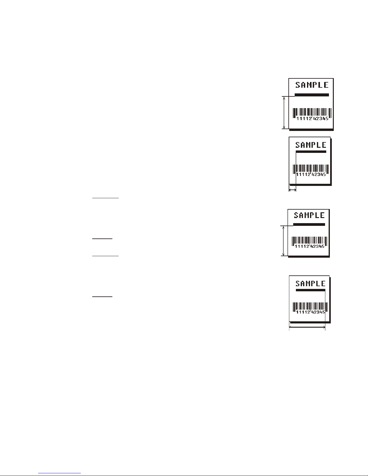
Syntax L,type,row,column,angle/end row,length/end col,thickness,
"pattern" p
L1. L Line Field.
L2. type Type of line. Only vertical and horizontal lines are supported. Options:
S Segment. You choose the starting point and
ending point.
V Vector. You choose the starting point, angle, and
length.
L3. row Distance from bottom of print area to the starting point.
English 0 - 999
Metric 0 - 2539
203 Dots 0 - 2029
300 Dots 0 - 2699
L4. column Distance from left edge of the print area to line origin.
English 0 - 399
Metric 0 - 1015
203 Dots 0 - 811
300 Dots 0 - 1199
L5. angle
/end row
L6. length/
end col
If Using Segments:
Row location of ending point. Measure from bottom
of the print area. Ranges same as row above. On
horizontal lines, this value must match item L3.
If Using Vectors:
Angle of line. Options: 0, 90, 180, or 270.
If Using Segments:
Column location of end point. Measure from left edge of print area.
Ranges same as column above. On vertical lines, this value must
match parameter L4.
If Using Vectors:
Length of the line in selected units.
Ranges for horizontal lines:
English 0 - 399
Metric 0 - 1015
203 Dots 0 - 811
300 Dots 0 - 1199
Ranges for vertical lines:
English 0 - 999
Metric 0 - 2539
203 Dots 0 - 2029
300 Dots 0 - 2699
3-18 DEFINING FIELDS
Page 49
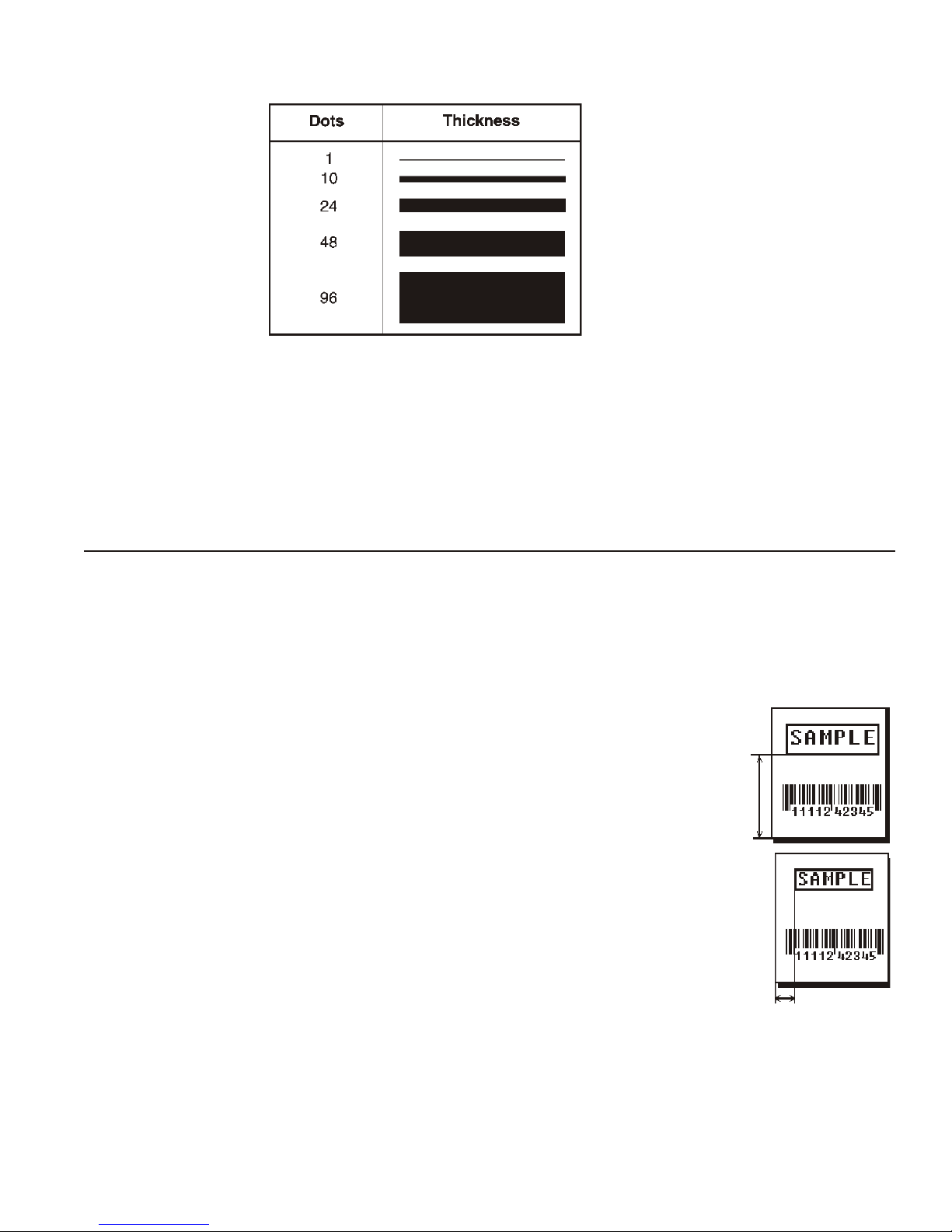
L7. thickness Using the chart below for reference, write the line thickness
(1 to 99) in box L7. Line thickness fills upward on horizontal lines, or to the right on vertical lines.
Measured in dots.
L8. “pattern” Line pattern. Enter "".
Example L,S,110,30,110,150,10,"" p
Defines a horizontal line field as a segment starting at row 110, column 30 and ending at row
110, column 150. The line thickness is 10 dots.
Defining Box Fields
Use boxes to form borders or highlight items of interest. Define each box field separately. This
field is not assigned a field number, but is counted as a field (keep this in mind, as the printer
allows a maximum of 1000 fields per format). You can define any line length and a thickness up
to 99 dots, as long as the solid black print does not exceed 25 percent of any given square inch
of the label.
Syntax Q,row,column,end row,end col,thickness,"pattern" p
Q1. Q Box (Quadrilateral) Field.
Q2. row Distance from bottom of print area to
lower left corner of box.
English 0 - 999
Metric 0 - 2539
203 Dots 0 - 2029
300 Dots 0 - 2699
Q3. column Distance from left edge of print area to lower left corner of box.
English 0 - 399
Metric 0 - 1015
203 Dots 0 - 811
300 Dots 0 - 1199
DEFINING FIELDS 3-19
Page 50
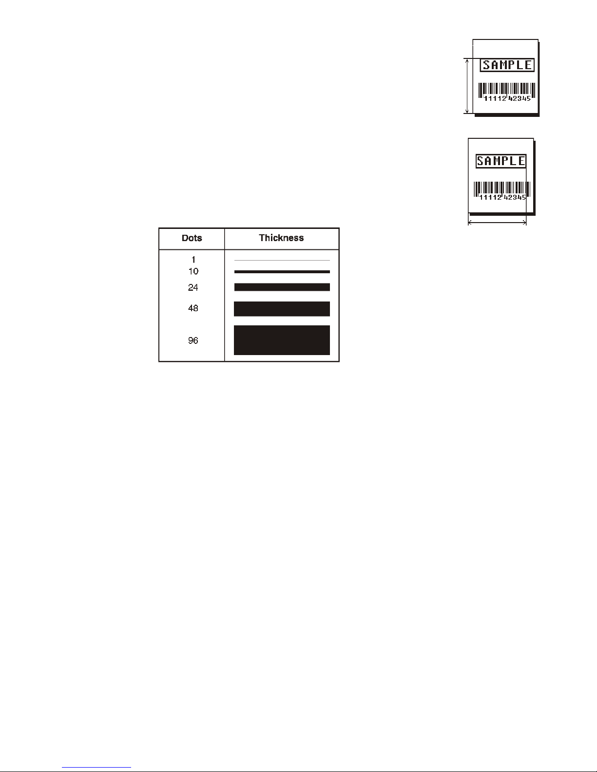
Q4. end row Distance from bottom of print area to upper right corner of box. Ranges
same as row.
Q5. end col Distance from left edge of print area to upper right corner of box. Ranges
same as column.
Q6. thickness Using the chart below for reference, write the desired line thickness
(1 to 99) in box Q6. Boxes fill inward, so make sure your boxes do not
overwrite other fields. Measured in dots.
Q7. “pattern” Line pattern. Enter "".
Example Q,40,30,70,150,3,"" p
Defines a box field starting at row 40, column 30. It ends at row 70, column 150. It has a
thickness of 3 dots.
3-20 DEFINING FIELDS
Page 51

DEFINING FIELD OPTIONS 4
This chapter provides a reference for defining
¨
field options in formats
¨
check digit packets.
Note: When using multiple options on the printer, options are processed in the
order they are received.
Applying Field Options
Field options further define text, bar code, and non-printable text fields. The
text, constant text, or bar code field must be previously defined before you can
apply any field option to it. Define options immediately after the field to which
they apply.
Combining Field Options
You can use more than one option with most fields. For example, you can use
Option 4 to copy data from another field, and then use Option 30 to pad the
field. When you use multiple options for the same field, you must place the
options in the order you want to apply them to your format.
DEFINING FIELD OPTIONS 4-1
Page 52

Restrictions
Some options cannot be used together. For example, incrementing (Option 60) and price field
(Option 42) options cannot be applied to the same field. Refer to the following sections
addressing individual options for specific combinations to avoid.
Option 4 (copy a field) is the only option that can be repeated for a single field.
Example R,1,3,1,3,1,1 p
Syntax R,option#,parameter...parameter p
R1. R Indicates field option header.
R2. option# Option number:
1 Define fixed characters
4 Copy data from previous field
30 Pad data to left or right with specified character
31 Generate check digit
42 Format as a price field
50 Define bar code densities
51 Define security and truncation of PDF417 bar codes
52 Define width or length of PDF417 bar codes
60 Define incrementing or decrementing field
61 Reimage fields
R3. parameter(s)
Varies per option. See the following option descriptions.
Option 1 (Fixed Data)
Fixed data is information (a company name or store number) you want to print on all labels. You
can define fixed characters for an entire field or for part of a field.
Syntax R,1,"fixed char" p
R1. R Option Header.
R2. 1 Option 1.
R3. fixed char Characters to insert. Enclose in quotation marks. If you are defining fixed characters for part of a
field, place underscores(_) in non-fixed positions. Any spaces in the phrase are fixed characters.
Range: 0 to 2710.
Note: Underscore characters are stripped out and the data is compressed if no data is supplied
by the batch and the field length is variable.
Example R,1,"_ _ _%$_ _ _ _ _" p
Uses fixed characters (%$) in positions 4 and 5. The other positions are variable.
Example R,1,"MONARCH" p
“MONARCH” appears as a fixed field in this example.
To fill in the non-fixed portion of the field, see “Defining Batch Data Fields” in Chapter 6. As an
alternative, you can apply Option 4 to copy data into the non-fixed character positions.
4-2 DEFINING FIELD OPTIONS
Page 53

Option 4 (Copy Data)
You can create a field that uses data from another field. This is useful for creating merged
fields or sub-fields. You can copy the information from multiple fields into one field by applying
the copy procedure more than once. Copy data is the only option you can apply to a field more
than once.
The maximum number of characters defined in box T3 or B3 must allow for the number of
characters you will place in the field, including any price, check digit, or fixed characters
inserted by the printer. The maximum number of characters in the field into which data is copied
cannot exceed 2710 or the maximum number of characters permitted by the bar code.
Note: When copying from more than one field, copy into the destination field from left to right.
Syntax R,4,src fld,src start,# to copy,dest start,copy code p
R1. R Field Option Header.
R2. 4 Option 4.
R3. src fld Field number from which data is copied. Range: 0 to 999.
R4. src start Position number in the source field of the first character to be copied. Character positions are
numbered 1 to 2710, starting from the left.
R5. # to copy Number of characters to copy. Range: 1 to 2710.
R6. dest start Position number where copied characters are to begin printing in the destination field. Range: 1 to
2710.
R7. copy code Copy Method.
1 Copy field as is (including price symbols, pad characters, check digits, etc.).
2 Copy unformatted data (without price characters, pad characters, etc.).
Example R,4,3,1,3,1,1 p
Copies data from field #3, starting at the first position and copying three characters. In the
destination field, the information is placed in position 1 and copied as formatted data.
Merging Fields
You can copy data to merge the contents of fields. Use the copy data option as many times as
necessary to copy all the appropriate fields into the merged field.
In the following example, two text and two non-printable fields are shown. Data from these
fields is merged to form field 5, and is then printed as a bar code.
Field Data Field Type
1 203 Non-printable
2 339 Non-printable
3 8 Tex t
4 BLUE Text
5 2033398BLUE Bar Code
To create this sequence:
1. Define fields 1, 2, 3, and 4.
2. Define field 5 as a bar code. Allow enough characters in the bar code field to hold all the
copied characters.
3. Apply Option 4 to field 5 once for every source field.
DEFINING FIELD OPTIONS 4-3
Page 54

Sub-Fields
You can copy a segment of data from one field into a new location, called a sub-field. For
example, extract part of the data in a bar code and display it in text form in a sub-field. Then,
use the copy data option.
Option 30 (Pad Data)
You can add characters to one side of a field to “pad” the field. Padding allows you to fill in the
remaining spaces when the entered data does not fill an entire field. If a variable length field is
not completely filled with batch data, this option fills the remaining positions in the field with the
character designated by Option 30.
Syntax R,30,L/R,"character" p
R1. R Option Header.
R2. 30 Option 30.
R3. L® Indicates type of padding:
L Pad field on left side
R Pad field on right side
R4. “character” Pad character must be within the 0 to 255 decimal range and enclosed inside quotation marks.
Note: Do not use on fixed length fields.
Example R,30,L,"X" p
Pads data with an “X” on the left side of the field.
Sample Use for Padding
If you have a variable length bar code that you want to occupy a fixed amount of space on the
supply, use pad characters. If the maximum number of characters in the bar code is 15, but the
batch record only has 10 characters, the padding option fills the remainder of the field with pad
characters.
Option 31 (Calculate Check Digit)
The printer generates a check digit if you apply Option 31 to the field. You cannot use this
option if the field contains a UPC, EAN, or Code 39 (with the MOD43 check digit) bar code.
Syntax R,31,gen/ver,check digit # p
R1. R Option Header.
R2. 31 Option 31.
R3. gen/ver Enter G to generate a check digit.
R4. check digit # Specifies a check digit scheme. Enter a number that identifies a check digit scheme that has been
defined. For more information, see “Using Check Digits.” Range: 1 to 10.
Example R,31,G,5 p
Generates a check digit using the previously defined check digit scheme 5.
4-4 DEFINING FIELD OPTIONS
Page 55

Option 42 (Price Field)
You can apply options that automatically inserts monetary symbols. Do not use this option with
Option 31 (define a check digit), Option 60 (increment or decrement a field) or bar code fields.
When determining the maximum number of characters, add the maximum number of digits and
the monetary symbols.
Syntax R,42,app code p
R1. R Option Header.
R2. 42 Option 42.
R3. app code Appearance code. Enter 1 to print price field in standard notation, as defined by country setting.
Use the monetary formatting packet to select monetary notations and symbols by country setting.
See “Defining the Monetary Formatting Packet” for more information.See Appendix C, “Symbol
Sets/Code Pages,” to make sure the monetary symbol you want to use is printable in the font
selected for this field. For monetary symbols other than the dollar sign, use the internal symbol set.
Example R,42,1 p
Uses a price field that prints the monetary symbol and notations as defined in the monetary
formatting packet.
Option 50 (Bar Code Density)
You can apply this option to bar code fields when you want to create custom densities. When
you apply this option, it overrides the density value in the bar code field. When using this
option, set the density parameter in your bar code field to the default value. You can only use
this option once for each bar code field.
Bar codes produced using Option 50 may not be scannable. The additional character gap,
narrow space, and wide space parameters are valid only with Code 39 and Codabar. If these
parameters are specified for any other bar codes, they will be ignored by the printer. Do not use
Option 50 with fixed density bar codes.
Option 50 can be used with PDF417 bar codes for specific customer ratios. With PDF417 bar
codes, use only the narrow and wide parameters. The narrow parameter defines the individual
bar width in dots and the wide parameter is used to define the height of each individual stacked
bar code. Option 50 can also be used with Option 52 to further customize the dimensions of a
PDF417 bar code. Option 52 allows customization of the number of columns or number of rows
for the bar code.
Syntax R,50,narrow,wide,gap,nar_space,wide_space p
R1. R Field Option Header.
R2. 50 Option 50.
R3. narrow Dot width of the narrow element. Range: 1 to 99.
R4. wide Dot width of the wide element. Range: 1 to 99.
R5. gap Additional dot space between characters. Enter a value of 1 to 99. (Code 39 and Codabar only.)
R6. nar_space Additional dot width of the narrow bar code space. (Code 39 and Codabar only). Range: 1 to 99.
R7. wide_space Additional dot width of the wide bar code space. (Code 39 and Codabar only). Range: 1 to 99.
Example R,50,4,8,4,4,8 p
Creates a custom bar code density with a narrow element of 4 dots, a wide element of 8 dots, a
gap of 4 dots, 4 additional dot widths for the narrow bar code space, and 8 additional dot widths
for the wide bar code space (if this is a Code 39 or Codabar bar code).
DEFINING FIELD OPTIONS 4-5
Page 56

Option 51 (PDF417 Security/Truncation)
You can define a security level and choose whether or not to truncate a PDF417 bar code.
Higher security levels add data to a bar code, improving scan reliability. Some damaged bar
codes may still be scannable if the security level is high enough. You can use this option to
create standard PDF417 bar codes or use the truncated option to create a narrower bar code.
This option can appear only once per PDF417 field, in any order, following the bar code field.
As the security level is increased, so is the size of your PDF417 bar code. For each level
increased, the bar code will double in size.
Syntax R,51,security,stand/default p
R1. R Option Header.
R2. 51 Indicates Option 51.
R3. security Security level ranges from 0 to 8 (0 is the default).
Higher security levels add data to a bar code, improving scan reliability. Some damaged bar codes
may still be scannable if the security level is high enough.
R4. stand/def Truncation selector. Valid values:
S (default) a standard PDF417 bar code
T truncated
Example R,51,2,S p
Defines a security level of 2 for a standard PDF417 bar code.
Option 52 (PDF417 Width/Length)
This option defines the image width or length of a PDF417 bar code. If you define a fixed
number of columns (width), the bar code expands in length. If you define a fixed number of
rows (length), the bar code expands in width.
Column value does not include start/stop or left/right indicator columns.
If this option does not immediately follow the PDF417 bar code field, the default settings are
used. You can only use this option once per PDF417 bar code field.
Syntax R,52,row/column,dimension p
R1. R Option Header.
R2. 52 Indicates Option 52.
R3. row/column Indicates if you are defining the number of rows or columns.
R Row
C Column
If you specify rows, the bar code expands in columns,
or vice versa.
R4. dimension The number of rows or columns defined for the bar code.
The default is 4. Valid values:
3-90 for rows
1-30 for columns
Example R,52,C,10 p
Defines the column width of 10, which expands the PDF417 bar code length by 10.
4-6 DEFINING FIELD OPTIONS
Page 57

Option 60 (Incrementing/Decrementing Fields)
You may have an application, such as serial numbers, in which you need a numeric field to
increment (increase in value) or decrement (decrease in value) on successive tickets within a
single batch. Incrementing or decrementing can be applied to numeric data only. If you have a
field that includes letters and digits, apply incrementing or decrementing to only the portion of
the field that contains digits. Do not use with Option 42 (price field).
Syntax R,60,I/D,amount,l pos,r pos p
R1. R Option Header.
R2. 60 Option 60.
R3. I/D Increment or decrement:
I incrementing field
D decrementing field
R4. amount Amount to increase or decrease. Range: 0 to 999.
R5. l pos Leftmost position in inc/dec portion of field. If this value is not entered, the default value 1 is used.
Range: 0 to 2710.
R6. r pos Rightmost position in inc/dec portion of field. If this value is not used, the entire field length is used
as the default. Range: 0 to 2710.
Example R,60,I,5,1,6 p
Increments a field by 5 each time the field is printed. The field increments beginning with the
first left position and ending with the sixth position.
Fixing the First Number in the Incrementing Sequence
There are two ways to enter the first number in the incrementing sequence. You can use batch
data or use Option 1 to define the first number as a fixed character. The first number in the
sequence must contain the same amount of digits as the highest number to be counted. For
example, to count the numbers 1 to 999, the first number in the sequence must be entered as
001.
DEFINING FIELD OPTIONS 4-7
Page 58
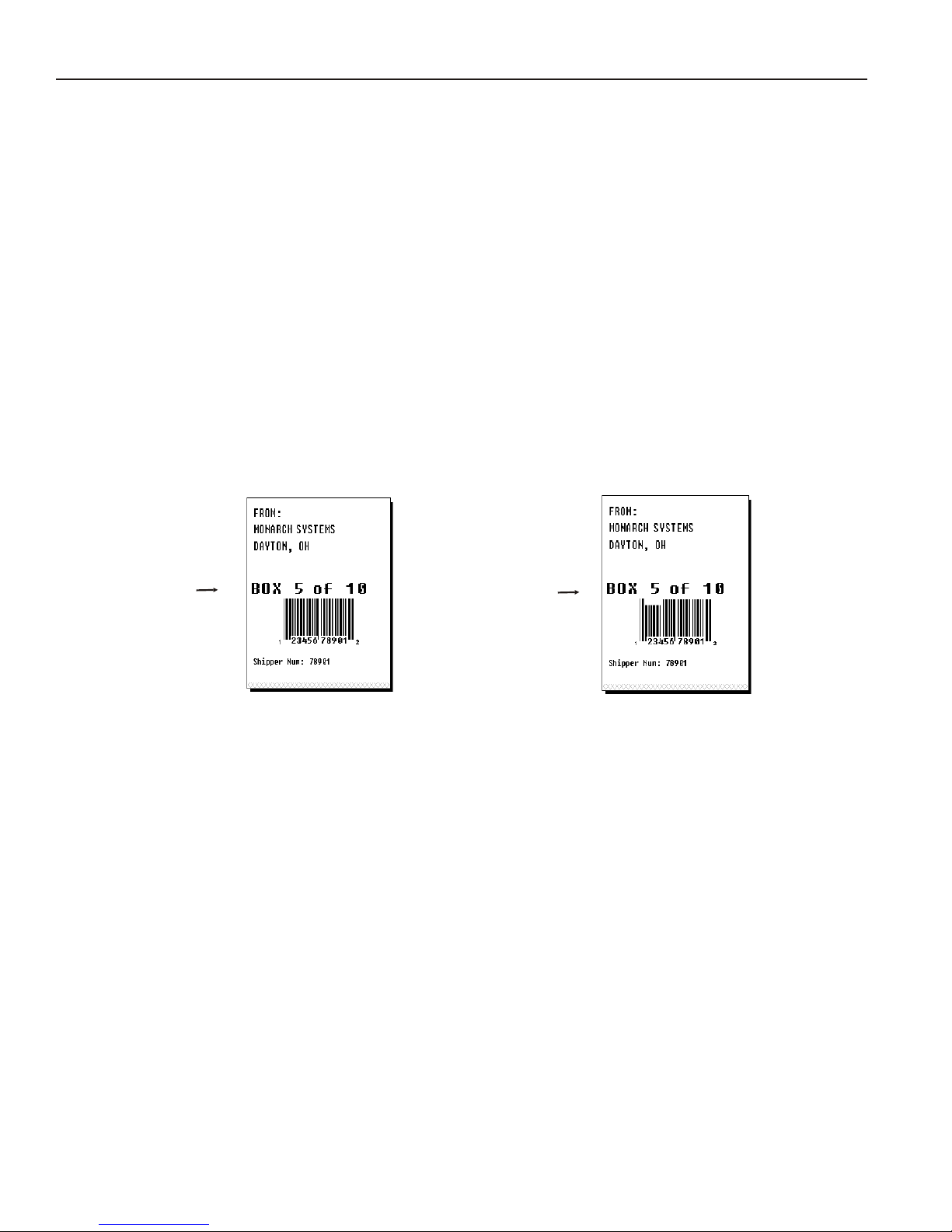
Option 61 (Re-image Field)
This option redraws (reimages) a constant field when you have a constant field next to a
variable field on your label. It can be used on text, constant text, bar code, line, or box fields.
These printers do not redraw an area if the field data does not change. When a field changes,
that area is cleared and the new field data is imaged. However, the new field data may require
a larger area than the previous field did. In some cases, neighboring fields that do not change
(constant fields) may be covered with white space from the changing field’s (variable fields)
area. Use this option to reimage the constant field, or it may appear broken.
Note: The most common use for this option is with incrementing fields on your label, because
they may cover a constant field.
Syntax R,61 p
R1. R Option Header.
R2. 61 Option 61.
Example R,61
Reimages the constant field that appears next to a variable field.
Re-Image
ON
Re-Image ON
Re-Image
OFF
Re-Image OFF
In the above example, Option 61 was applied to the bar code field to keep the incrementing field
(Box #) from blocking out the bar code field.
4-8 DEFINING FIELD OPTIONS
Page 59

Using Check Digits
Check digits are typically used to ensure that a text or bar code field scans correctly. If you
apply Option 31, the printer calculates a check digit. A check digit scheme determines how the
printer calculates a check digit. When you define a check digit scheme, you assign a number to
identify it. This number is later entered in box R4 when you apply Option 31 to a field. You can
use check digits with text or bar code fields. Check digit calculations are performed on numeric
data only.
Do not use check digits with price fields. Do not define a check digit scheme for UPC, EAN,
Code 39 (with the MOD43 check digit), and Code 93 bar codes, because they have predefined
check digits.
Syntax {A,selector,action,device,modulus, fld_length,D/P,"weights" p }
A1. A Check Digit Header.
A2. selector Assign a number from 1 to 10 to this check digit formula.
A3. action The action to perform. Enter A to add the check digit scheme.
A4. device Format storage device. Use R (Volatile RAM).
A5. modulus Number from 2 to 11. The modulus is used to divide the sum of products or the sum of digits.
A6. fld_length The maximum number of characters the field will contain.
Range: 0 to 2710.
A7. D/P Algorithm. The algorithm determines how the check digit is calculated.
Options:
D sum of digits
P sum of products
A8. “weights” String of digits used for calculation. A weight string is a group of two or more numbers that is
applied to a field. The number of digits in this string should equal the number in fld_length.
Enclose in quotation marks. Range: 0 to 2710.
Example {A,1,A,R,10,5,P,"65432" p }
Adds check digit scheme number 1 to the printer’s memory. The modulus is 10, the maximum
number of characters in the field is 5. The check digit is calculated by using the Sum of
Products and the string of digits used in the calculation is “65432.”
DEFINING FIELD OPTIONS 4-9
Page 60

Sum of Products Calculation
This is an example of how the printer uses Sum of Products to calculate a check digit for this
data:
5 2 3 2 4 5 2 1 9
1. Weights are applied to each digit, starting with the last digit in the weight string. They are
applied right to left, beginning at the right-most position of the field. Remember, a weight
string must contain at least two different numbers. This example has a weight string of
1,2,3,4:
field: 5 2 3 2 4 5 2 1 9
weight string: 4 1 2 3 4 1 2 3 4
2. Each digit in the field is multiplied by the weight assigned to it:
field: 5 2 3 2 4 5 2 1 9
weight string: 4 1 2 3 4 1 2 3 4
products: 20 2 6 6 16 5 4 3 36
3. Next, the product of each digit is added together. This is the sum of the products.
20 + 2 + 6 + 6 + 16 + 5 + 4 + 3 + 36 = 98
4. Divide the sum of the products by the modulus (10 in this case), only to the whole number.
The balance is called the remainder.
9
10 98
90
8
5. Subtract the remainder from the modulus.
The result becomes the check digit. In this case, the check digit is 2.
10 - 8 = 2
4-10 DEFINING FIELD OPTIONS
Page 61

Sum of Digits Calculation
This is an example of how the printer uses Sum of Digits to calculate a check digit for this data:
5 2 3 2 4 5 2 1 9
1. Weights are applied to each digit, starting with the last digit in the weight string. They are
applied right to left, beginning at the right-most position of the field. Remember, a weight
string must contain at least two different numbers. This example has a weight string of
1,2,3,4:
field: 5 2 3 2 4 5 2 1 9
weight string: 4 1 2 3 4 1 2 3 4
2. Each digit in the field is multiplied by the weight assigned to it:
field: 5 2 3 2 4 5 2 1 9
weight string: 4 1 2 3 4 1 2 3 4
products: 20 2 6 6 16 5 4 3 36
3. Next, the digits of the products are added together. Two-digit products are treated as two
separate digits.
This is the sum of the digits.
2 + 0 + 2 + 6 + 6 + 1 + 6 + 5 + 4 + 3 + 3 + 6 = 44
4. Divide the sum of the digits by the modulus (10 in this case), only to the whole number. The
balance is called the remainder.
4
10 44
40
4
5. Subtract the remainder from the modulus.
The result becomes the check digit. In this case, the check digit is 6.
10 - 4 = 6
DEFINING FIELD OPTIONS 4-11
Page 62

4-12 DEFINING FIELD OPTIONS
Page 63

CREATING GRAPHICS 5
This chapter provides information on how to
¨
map out the graphic image using the hexadecimal (hex) or run length
method.
¨
create a graphic packet using a graphic header, bitmap, duplicate,
next-bitmap, text, constant text, line, and box fields.
¨
place a graphic image into a format.
You can use graphic packets to create bitmapped images. To include a graphic
packet within your format, your format must contain a graphic field. See
“Placing the Graphic in a Format” for more information.
CREATING GRAPHICS 5-1
Page 64
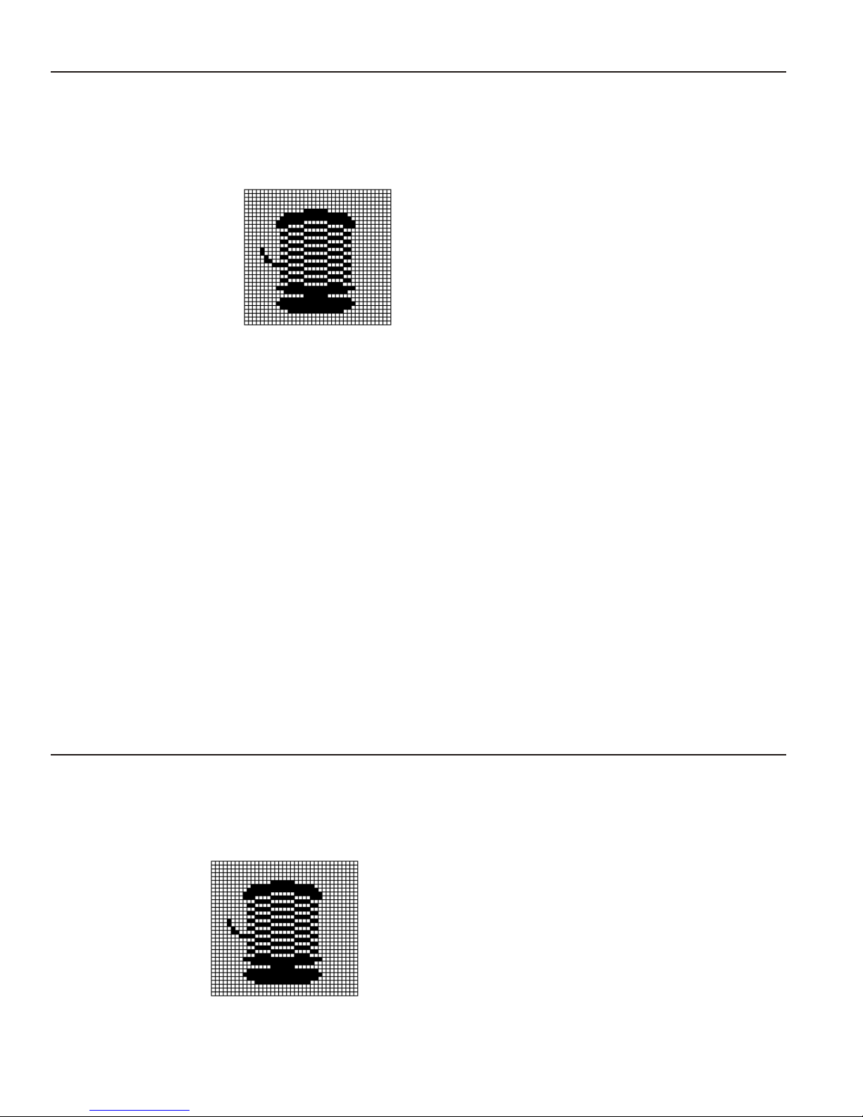
Overview of Bitmapped Images
A printed image is formed through a series of dots. Each square on the grid below represents a
dot on the printhead. The graphic image is created by blackening dots in a specific pattern.
You can print varying shades of gray according to the concentration of dots on the image. When
the dots are printed together, the end result is a graphic image.
Determining a Method
You can use one of two methods to map out your graphic image:
Hex Method The dot sequences are segmented into binary numbers and then converted
to hex numbers.
A graphic using gray-scaling, several slanted lines, or several vertical lines
typically translates more efficiently with hex representation.
Run Length
Encoding Method
The most efficient encoding method depends on how complicated your graphic image is and
whether or not imaging time is a concern. You may want to experiment with both encoding
methods to get optimal performance.
The dot sequences are segmented into black and white strings within a row.
The total count of each white string is converted to a lower-case letter,
corresponding to numeric value. The total count of each black string is
converted to an uppercase letter, corresponding to numeric value. This
method can reduce imaging time for graphics that contain repetitive rows of
dots. A graphic with horizontal lines or very few white-to-black borders
typically translates more efficiently with run length encoding.
Designing Bitmapped Images
Once you determine the encoding method to use, you can begin mapping out your graphic
image.
Note: The image that you map must be an upside down mirror image of the final result.
5-2 CREATING GRAPHICS
Page 65
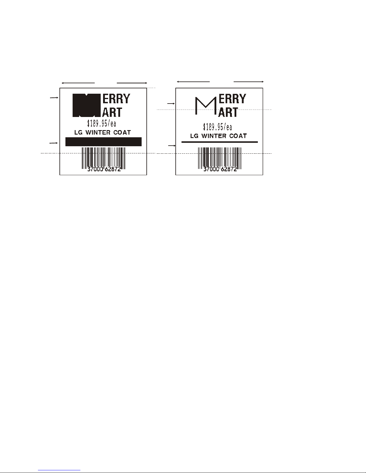
Special Considerations
Solid black print cannot exceed 25% of any given square inch of the supply. If the black print
exceeds this limit, you may lose data or damage the printhead.
In the first label, the large “M” logo and thick black line exceed the allowed black to white print
ratio. In the second label, the large “M” logo does not exceed the black to white print ratio.
2 inches
0.5"
Exceeds
Limit
2 inches
0.5"
Does not
exceed
limit
Exceeds
Limit
Does not
exceed
limit
Using the Hex Method
The following steps explain how to derive a hex character string from a bitmapped graphic.
Each square on the grid represents a dot. A black square indicates the dot is ON, and a white
square indicates the dot is OFF. A sequence of binary numbers, called a bit pattern or bitmap,
determines what dots are on and off. The numbers “0" and ”1" are used for this purpose. The
number “1" turns a dot on and ”0" turns a dot off.
All hex numbers must be two digits. For example, write hex 0 as 00, or hex E as 0E.
1. Assign 1 to every black square and 0 to every white square.
00000000000000000000000000000000000000000000000000111111111111111111111111110000000000000000000000000000
00000000000000000000000000000000000000011111111111000000000000000000000000001111111110000000000000000000
00000000000000000000000000000000001111100000000000000000000000000000000000000000000001111110000000000000
00000000000000000000000000000011110000000000000000111111111111111111111111110000000000000001111000000000
00000000000000000000000001111100001111111111111111111111111111111111111111111111111111111110000111110000
00000000000000000000000110000011111111111111111111111111111111111111111111111111111111111111111000001100
00000000000000000000000110001111111111111111111111111111111111111111111111111111111111111111111111111110
00000000000000000000000111111111111111111111111111111111111111111111111111111111111111111111111111111110
00000000000000000000000111111111111111111111111111111000000000000000000011111111111111111111111111111110
00000000000000000000000111111111111111111111000000000000000000000000000000000000011111111111111111111100
00000000000000000000000001111111100000000000000000000111111111111111111100000000000000000011111111110000
00000000000000000000000000011111110000000000000000000111111111111111111100000000000000000001111111000000
00000000000000000000000000011100000000111111111111111111111111111111111111111111111111100000000111000000
00000000000000000000000000000000001111111111111111111111111111111111111111111111111111111110000111000000
00000000000000000000000000000011111111111111000000000000000000000000000000000000011111111111111000000000
00000000000000000000000000011111110000000000000000000111111111111111111100000000000000000001111111000000
00000000000000000000000000011100000000111111111111111111111111111111111111111111111111100000000111000000
00000000000000000000000000000000001111111111111111111111111111111111111111111111111111111110000111000000
00000000000000000000000000000011111111111111000000000000000000000000000000000000011111111111111000000000
00000000000000000000000000011111110000000000000000000111111111111111111100000000000000000001111111000000
00000000000000000000000000011100000000111111111111111111111111111111111111111111111111100000000111000000
00000000000000000000000000000000001111111111111111111111111111111111111111111111111111111110000111000000
00000000000000000000000000000011111111111111000000000000000000000000000000000000011111111111111000000000
00000000000000000000000000011111110000000000000000000111111111111111111100000000000000000001111111000000
00000000000000000000000000011100000000111111111111111111111111111111111111111111111111100000000111000000
00000000000000000000000000000000001111111111111111111111111111111111111111111111111111111110000111000000
00000000000000000000000000000011111111111111000000000000000000000000000000000000011111111111111000000000
00000000000000000000000000011111110000000000000000000111111111111111111100000000000000000001111111000000
00000000000000000000000000011100000000111111111111111111111111111111111111111111111111100000000111000000
00000000000000000000000000000000001111111111111111111111111111111111111111111111111111111110000111000000
00000000000000000000000000000011111111111111000000000000000000000000000000000000011111111111111000000000
00000010000000000000000000011111110000000000000000000111111111111111111100000000000000000001111111000000
00000011000000000000000000011100000000111111111111111111111111111111111111111111111111100000000111000000
00000001111000000000000000000000001111111111111111111111111111111111111111111111111111111110000111000000
00000000111000000000000000000011111111111111000000000000000000000000000000000000011111111111111000000000
00000000111111000000000000011100000000111111111111111111111111111111111111111111111111100000001111000000
00000000111111100000000000000000001111111111111111111111111111111111111111111111111111111110001111000000
CREATING GRAPHICS 5-3
Page 66

2. Section off the grid in columns of eight. If any rows are not divisible by 8, add enough 0’s to
complete a column.
00000000 00000000 00000000 00000000 00000000 00000000 00111111 11111111 11111111 11110000 00000000 00000000 00000000
00000000 00000000 00000000 00000000 00000001 11111111 11000000 00000000 00000000 00001111 11111000 00000000 00000000
00000000 00000000 00000000 00000000 00111110 00000000 00000000 00000000 00000000 00000000 00000111 11100000 00000000
00000000 00000000 00000000 00000011 11000000 00000000 00111111 11111111 11111111 11110000 00000000 00011110 00000000
00000000 00000000 00000000 01111100 00111111 11111111 11111111 11111111 11111111 11111111 11111111 11100001 11110000
00000000 00000000 00000001 10000011 11111111 11111111 11111111 11111111 11111111 11111111 11111111 11111110 00001100
00000000 00000000 00000001 10001111 11111111 11111111 11111111 11111111 11111111 11111111 11111111 11111111 11111110
00000000 00000000 00000001 11111111 11111111 11111111 11111111 11111111 11111111 11111111 11111111 11111111 11111110
00000000 00000000 00000001 11111111 11111111 11111111 11111000 00000000 00000000 11111111 11111111 11111111 11111110
00000000 00000000 00000001 11111111 11111111 11110000 00000000 00000000 00000000 00000000 01111111 11111111 11111100
00000000 00000000 00000000 01111111 10000000 00000000 00000111 11111111 11111111 00000000 00000000 00111111 11110000
00000000 00000000 00000000 00011111 11000000 00000000 00000111 11111111 11111111 00000000 00000000 00011111 11000000
00000000 00000000 00000000 00011100 00000011 11111111 11111111 11111111 11111111 11111111 11111110 00000001 11000000
00000000 00000000 00000000 00000000 00111111 11111111 11111111 11111111 11111111 11111111 11111111 11100001 11000000
00000000 00000000 00000000 00000011 11111111 11110000 00000000 00000000 00000000 00000000 01111111 11111110 00000000
00000000 00000000 00000000 00011111 11000000 00000000 00000111 11111111 11111111 00000000 00000000 00011111 11000000
00000000 00000000 00000000 00011100 00000011 11111111 11111111 11111111 11111111 11111111 11111110 00000001 11000000
00000000 00000000 00000000 00000000 00111111 11111111 11111111 11111111 11111111 11111111 11111111 11100001 11000000
00000000 00000000 00000000 00000011 11111111 11110000 00000000 00000000 00000000 00000000 01111111 11111110 00000000
00000000 00000000 00000000 00011111 11000000 00000000 00000111 11111111 11111111 00000000 00000000 00011111 11000000
00000000 00000000 00000000 00011100 00000011 11111111 11111111 11111111 11111111 11111111 11111110 00000001 11000000
00000000 00000000 00000000 00000000 00111111 11111111 11111111 11111111 11111111 11111111 11111111 11100001 11000000
00000000 00000000 00000000 00000011 11111111 11110000 00000000 00000000 00000000 00000000 01111111 11111110 00000000
00000000 00000000 00000000 00011111 11000000 00000000 00000111 11111111 11111111 00000000 00000000 00011111 11000000
00000000 00000000 00000000 00011100 00000011 11111111 11111111 11111111 11111111 11111111 11111110 00000001 11000000
00000000 00000000 00000000 00000000 00111111 11111111 11111111 11111111 11111111 11111111 11111111 11100001 11000000
00000000 00000000 00000000 00000011 11111111 11110000 00000000 00000000 00000000 00000000 01111111 11111110 00000000
00000000 00000000 00000000 00011111 11000000 00000000 00000111 11111111 11111111 00000000 00000000 00011111 11000000
00000000 00000000 00000000 00011100 00000011 11111111 11111111 11111111 11111111 11111111 11111110 00000001 11000000
00000000 00000000 00000000 00000000 00111111 11111111 11111111 11111111 11111111 11111111 11111111 11100001 11000000
00000000 00000000 00000000 00000011 11111111 11110000 00000000 00000000 00000000 00000000 01111111 11111110 00000000
00000010 00000000 00000000 00011111 11000000 00000000 00000111 11111111 11111111 00000000 00000000 00011111 11000000
00000011 00000000 00000000 00011100 00000011 11111111 11111111 11111111 11111111 11111111 11111110 00000001 11000000
00000001 11100000 00000000 00000000 00111111 11111111 11111111 11111111 11111111 11111111 11111111 11100001 11000000
00000000 11100000 00000000 00000011 11111111 11110000 00000000 00000000 00000000 00000000 01111111 11111110 00000000
00000000 11111100 00000000 00011100 00000011 11111111 11111111 11111111 11111111 11111111 11111110 00000011 11000000
00000000 11111110 00000000 00000000 00111111 11111111 11111111 11111111 11111111 11111111 11111111 11100011 11000000
3. One row at a time, convert each group of eight binary digits to hex.
starting at position 49 …
00111111 = 3F
11111111 = FF
11111111 = FF
11110000 = F0
4. Write the hex values for each row as a continuous string.
row 1, position 49 = 03FFFFFF00000
5. Repeat steps 3 through 4 for each row on the grid.
6. Insert the hex values in syntax format.
5-4 CREATING GRAPHICS
Page 67

Using the Run Length Encoding Method
The following steps explain how to derive a run length character string from a bitmapped
graphic.
Each square on the grid represents a dot. A black square indicates the dot is ON, and a white
square indicates the dot is OFF.
Note: The following example shows “1" to indicate when a square is ON, and ”0" to indicate
when a square is OFF. You do not have to convert your dots when using the run length
method.
00000000 00000000 00000000 00000000 00000000 00000000 00111111 11111111 11111111 11110000 00000000 00000000 00000000
00000000 00000000 00000000 00000000 00000001 11111111 11000000 00000000 00000000 00001111 11111000 00000000 00000000
00000000 00000000 00000000 00000000 00111110 00000000 00000000 00000000 00000000 00000000 00001111 11000000 00000000
00000000 00000000 00000000 00000011 11000000 00000000 00111111 11111111 11111111 11110000 00000000 00011110 00000000
00000000 00000000 00000000 01111100 00111111 11111111 11111111 11111111 11111111 11111111 11111111 11100001 11110000
00000000 00000000 00000001 10000011 11111111 11111111 11111111 11111111 11111111 11111111 11111111 11111110 00001100
00000000 00000000 00000001 10001111 11111111 11111111 11111111 11111111 11111111 11111111 11111111 11111111 11111110
00000000 00000000 00000001 11111111 11111111 11111111 11111111 11111111 11111111 11111111 11111111 11111111 11111110
00000000 00000000 00000001 11111111 11111111 11111111 11111000 00000000 00000000 11111111 11111111 11111111 11111110
00000000 00000000 00000001 11111111 11111111 11110000 00000000 00000000 00000000 00000000 01111111 11111111 11111100
00000000 00000000 00000000 01111111 10000000 00000000 00000111 11111111 11111111 00000000 00000000 00111111 11110000
00000000 00000000 00000000 00011111 11000000 00000000 00000111 11111111 11111111 00000000 00000000 00011111 11000000
00000000 00000000 00000000 00011100 00000011 11111111 11111111 11111111 11111111 11111111 11111110 00000001 11000000
00000000 00000000 00000000 00000000 00111111 11111111 11111111 11111111 11111111 11111111 11111111 11100001 11000000
00000000 00000000 00000000 00000011 11111111 11110000 00000000 00000000 00000000 00000000 01111111 11111110 00000000
00000000 00000000 00000000 00011111 11000000 00000000 00000111 11111111 11111111 00000000 00000000 00011111 11000000
00000000 00000000 00000000 00011100 00000011 11111111 11111111 11111111 11111111 11111111 11111110 00000001 11000000
00000000 00000000 00000000 00000000 00111111 11111111 11111111 11111111 11111111 11111111 11111111 11100001 11000000
00000000 00000000 00000000 00000011 11111111 11110000 00000000 00000000 00000000 00000000 01111111 11111110 00000000
00000000 00000000 00000000 00011111 11000000 00000000 00000111 11111111 11111111 00000000 00000000 00011111 11000000
00000000 00000000 00000000 00011100 00000011 11111111 11111111 11111111 11111111 11111111 11111110 00000001 11000000
00000000 00000000 00000000 00000000 00111111 11111111 11111111 11111111 11111111 11111111 11111111 11100001 11000000
00000000 00000000 00000000 00000011 11111111 11110000 00000000 00000000 00000000 00000000 01111111 11111110 00000000
00000000 00000000 00000000 00011111 11000000 00000000 00000111 11111111 11111111 00000000 00000000 00011111 11000000
00000000 00000000 00000000 00011100 00000011 11111111 11111111 11111111 11111111 11111111 11111110 00000001 11000000
00000000 00000000 00000000 00000000 00111111 11111111 11111111 11111111 11111111 11111111 11111111 11100001 11000000
00000000 00000000 00000000 00000011 11111111 11110000 00000000 00000000 00000000 00000000 01111111 11111110 00000000
00000000 00000000 00000000 00011111 11000000 00000000 00000111 11111111 11111111 00000000 00000000 00011111 11000000
00000000 00000000 00000000 00011100 00000011 11111111 11111111 11111111 11111111 11111111 11111110 00000001 11000000
00000000 00000000 00000000 00000000 00111111 11111111 11111111 11111111 11111111 11111111 11111111 11100001 11000000
00000000 00000000 00000000 00000011 11111111 11110000 00000000 00000000 00000000 00000000 01111111 11111110 00000000
00000010 00000000 00000000 00011111 11000000 00000000 00000111 11111111 11111111 00000000 00000000 00011111 11000000
00000011 00000000 00000000 00011100 00000011 11111111 11111111 11111111 11111111 11111111 11111110 00000001 11000000
00000001 11100000 00000000 00000000 00111111 11111111 11111111 11111111 11111111 11111111 11111111 11100001 11000000
00000000 11100000 00000000 00000011 11111111 11110000 00000000 00000000 00000000 00000000 01111111 11111110 00000000
00000000 11111100 00000000 00011100 00000011 11111111 11111111 11111111 11111111 11111111 11111110 00000011 11000000
00000000 11111110 00000000 00000000 00111111 11111111 11111111 11111111 11111111 11111111 11111111 11100011 11000000
1. Count the number of consecutive OFF or ON dots in a row. Write the number of consecutive
dots in sequence for the first row on the grid. Write “ON” or “OFF” after each number to
indicate ON or OFF dots.
(row 1, position 50) 26 on
(row 2, position 39) 11 on, 26 off, 9 on
(row 3, position 34) 5 on, 45 off, 6 on
2. Replace each number you have written with its corresponding code from the Dot to Run
Length Encoding Chart provided in Appendix C, “Symbol Sets/Code Pages.” Be sure to use
CAPITAL letters for black dots and lower-case letters for white dots.
26 on (Z)
11 on (K), 26 off (z), 9 on (I)
If the number is greater than 26, write z, followed by the letter corresponding to the amount
over 26. For example, to represent 45 off dots, write zs.
5 on (E), 45 off (zs), 6 on (F)
3. Write the letter codes in sequence, uninterrupted, for each row.
(row 1,position 50) Z
(row 2,position 39) KzI
(row 3,position 34) EzsF
(row 4,position 30) DpZoD
Note: If the end of the line specifies OFF dots (lower-case letters), the ending lower-case
letters can be omitted. For example, uZFu can be written as uZF.
4. Repeat steps 1 through 5 for each row on the grid.
5. Insert the code values in syntax format.
CREATING GRAPHICS 5-5
Page 68

Determining How to Store the Image
Once you have mapped out your graphic image, determine how you want to store it. You have
several options:
¨ Volatile RAM
¨ Temporary Storage
¨ Memory Card
Using Volatile RAM
You should use RAM when the graphic image is used by several formats, because you only
have to send the graphic image once. This eliminates the need to send the graphic image
repeatedly. See “Placing the Graphic in a Format,” for more information about using the graphic
packet in a format. Graphics smaller than approximately ½ inch by ½ inch can be stored in
printer RAM and referenced by the graphic ID number.
Graphics are stored in the format buffer and remain there until another graphic packet is sent or
the printer is turned off.
Using Temporary Storage
You should use temporary storage when the graphic image is used only in one format or your
graphic image is very large. Graphic data in temporary storage is held in the image buffer until
the graphic is printed and then it is cleared from memory. Temporary graphics are also cleared
from memory when you send a new batch or update batch. You can use the same graphic
image multiple times on a format. Send the graphic image to the printer after the format to
which it applies.
If a graphic is stored in temporary storage, do not place a graphic field in the format. This
causes an error. Instead, position the graphic image by using the row and column locations in
the graphic packet header. Image memory (temporary storage) accepts a graphic packet 1218
rows long with 811 dots per row.
Using a Memory Card
The 9416XL printer has an optional memory card that allows storage of formats, graphics, and
fonts. Graphics stored on the memory card are saved when the printer is turned off. Use M in
the Graphic header. See "Defining the Graphic Header" for more information.
Creating a Graphic Packet
Your graphic packet can contain
¨ bitmapped fields (for bitmapped images)
¨ constant text fields
¨ lines
¨ boxes.
Images using hex representation or run length encoding are bitmapped images. See “Designing
Bitmapped Images” to design your bitmapped image.
Once you design your graphic image, you are ready to define a graphic packet. This packet
generates the graphic image you use in a format.
5-6 CREATING GRAPHICS
Page 69
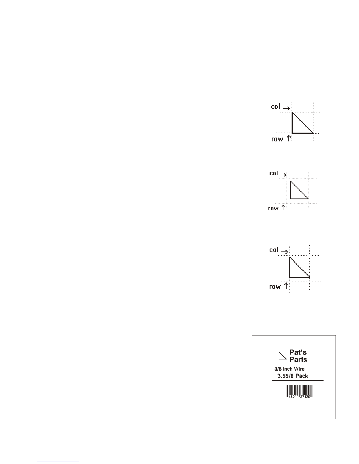
Positioning the Graphic Image
This section explains how to position the graphic image within a graphic packet header, a field
of a graphic packet, or within a format.
Within the Graphic Packet Header
When you are using RAM, the row and column parameters in the graphic header are usually 0,0,
because placement is controlled by the graphic field in your format. This is especially true when
designing a compliance label overlay.
When you are using temporary storage, these parameters control
the placement of the graphic image on the supply.
The area enclosed within the dotted lines represents the graphic
image starting at 0,0 (as defined in the graphic header).
If you want a fixed amount of white space around your graphic
image, use something other than 0 for row and/or column.
The area enclosed within the dotted lines represents the graphic
image starting at 0,0 with a fixed amount of white space (10,10)
around the graphic image.
Within the Field
In a bitmap, constant text, line, or box field, the row and column
parameters control where an individual field or bitmapped row begins
in relation to the coordinates defined in the graphic header.
The bottom of the triangle in this example represents the first field of
the graphic packet starting at 10,0.
Within a Format
When you define the graphic field within your format, the row and
column parameters represent where on the format to place the
graphic image.
If you are doing a compliance label, these numbers are usually 0,0, because your compliance
label covers the entire supply. See "Placing the Graphic in a Format," for a sample compliance
label.
If you are placing a graphic (a logo, for example) within a certain
area on your supply, enter the starting position (bottom left corner)
of the graphic image.
This label shows the triangle “logo” beginning (the bottom left
corner) at 155, 33 as defined in the graphic field.
CREATING GRAPHICS 5-7
Page 70

Defining the Graphic Header
Every graphic packet must contain a graphic header. This is the first thing you enter. It
identifies and provides important measurement and formatting information for the graphic.
Bitmap, duplicate, next-bitmap, constant text, line, and box fields follow the graphic header, if
they are used.
Syntax {G,graphID,action,device,units,row,col, mode,"name" p
G1. G Graphic Header.
G2. graphID Unique number from 1 to 999 to identify the graphic image.
G3. action The action to perform to the graphic. Options:
A Add the graphic to the printer.
C Clear the graphic from the printer.
G4. device Graphic storage device. Options:
M Memory Card (only supported by the 9416XL printer with an
optional memory card).
R Volatile RAM (format must contain a graphic field)
T Temporary storage
G5. units Unit of measure. For bitmapped graphics, G (dots) is the only valid option.
G6. row Distance between the bottom of the graphic image area and the first bitmap line. This is usually 0,
unless you want a fixed amount of white space around the graphic image. See “Positioning the
Graphic Image,” for more information.
English 0 - 999
Metric 0 - 2539
203 Dots 0 - 2029
300 Dots 0 - 2699
G7. column Distance between the left edge of the graphic image area and the left edge of first bitmap line. This
is usually 0, unless you want a fixed amount of white space around the graphic image. See
“Positioning the Graphic Image,” for more information. Use the previous table for values.
English 0 - 399
Metric 0 - 1015
203 Dots 0 - 811
300 Dots 0 - 1199
G8. mode Imaging mode. Enter 0.
G9. “name” Graphic name (optional), 0 to 8 characters, enclose within quotation marks.
Example {G,99,A,R,G,0,0,0,"99Wire" p
Adds a graphic image identified by number 99 to volatile RAM. The graphic uses dot
measurement. The image will be placed according to the row and column parameters in the
graphic field. The imaging mode is 0 and the image is called 99Wire.
5-8 CREATING GRAPHICS
Page 71

Creating Bitmap Fields
This defines one row of dots, starting at a specific row and column within the graphic image.
Each unique row of dots requires a bitmap field. A bitmap field can later be repeated by using a
duplicate field.
Syntax B,row,column,algorithm,"data" p
B1. B Bitmap Field.
B2. row Distance (in dots) from the graphic image’s bottom margin to the bitmap line.
English 0 - 999
Metric 0 - 2539
203 Dots 0 - 2029
300 Dots 0 - 2699
B3. column Distance (in dots) from the graphic image’s left edge to the bitmap line.
English 0 - 399
Metric 0 - 1015
203 Dots 0 - 811
300 Dots 0 - 1199
B4. algorithm Coding method for bitmap data:
H Hex Representation
R Run Length Encoding
B5. data Character string made up of hex or run length encoding. Do not put spaces or any other character
between the numbers. Range: 0 to 2710.
Example {B,39,56,H,"3FFFFFF0" p
Defines a bitmapped graphic field. The image begins 39 dots from the bottom and 56 dots from
the left edge of the graphic area. Hex representation is used.
Creating Next-Bitmap Fields
This field uses the previous field’s row and column locations. It allows you to use the bitmap or
duplicate field data without having to recalculate row and column locations. This field
represents one row of dots on the image.
Syntax N,adjdir,adjamt,algorithm,"data" p
N1. N Next-Bitmap Field.
N2. adjdir Increments or decrements the row count. Inserts the duplicate line after or before the current row.
0 Increments (inserts after)
1 Decrements (inserts before)
For example:
B,50,35,R,"GsSsG" p
N,0,1,R,"DpZoD" p
prints a next-bitmap field on row 51 at column 35.
N3. adjamt Amount of row adjustment in dot rows. Using 0 overwrites the same line. Range: 0 to 999.
N4. algorithm Coding method for bitmap data:
H Hex Representation
R Run Length Encoding
N5. “data” Character string made up of hex or run length encoding. Do not put spaces or any other character
between the hex numbers or run length code letters. Range: 0 to 2710.
CREATING GRAPHICS 5-9
Page 72

Example B,39,56,H,"3FFFFFF0" p
N,0,1,H,"000000E00000" p
Defines a next-bitmap graphic field beginning on row 40. The row count increments by 1. Hex
representation is used.
Creating Duplicate Fields
If a line of data is identical to a previous bitmap or next-bitmap field, the duplicate field allows
you to repeat the dot sequence without retyping the data. A duplicate field represents one row
of dots on the image.
Note: Duplicate fields are useful when you have a graphic with a lot of repetition.
Syntax D,adjdir,adjamt,count p
D1. D Duplicate Field.
D2. adjdir Increments or decrements the row count. Inserts the duplicate line after or before the current row.
0 Increments (inserts after)
1 Decrements (inserts before)
For example:
B,50,35,R,"GsSsG" p
D,0,20,2 p
inserts row 50 again at row 70 and row 90. Rows 70 and 90 do not have to be defined
later.
D3. adjamt Amount of row adjustment in dot rows. Range for 203 dpi: 0 to 999;
range for 300 dpi: 0 to 2699. The above example adjusts the duplicate field to image on row 70
and 90 (adding 20 to the current row count).
D4. count Number of times to duplicate the line. Range: 0 to 999.
Example B,117,24,H,"03FFFFFFFFFFFFFFFFFFFC" p
D,0,1,2 p
Defines a duplicate field that is imaged after the bitmap line. This field duplicates the preceding
bitmap line twice (at row 118 and 119).
You can use constant text, line, or box fields in a graphic packet to create a compliance label
overlay. See Chapter 3, “Defining Fields,” for more information about these fields.
5-10 CREATING GRAPHICS
Page 73

Sample Hex Graphic Packet
{G,99,A,R,G,0,0,0,"99WIRE"p
B,39,48,H,"3FFFFFF0" p
B,40,32,H,"01FFC000000FF8"p
B,41,32,H,"3E00000000000FC0" p
B,42,24,H,"03C0003FFFFFF0000F"p
B,43,24,H,"7C3FFFFFFFFFFFFFE1F0" p
B,44,16,H,"0183FFFFFFFFFFFFFFFF06" p
B,45,16,H,"018FFFFFFFFFFFFFFFFFFE" p
B,46,16,H,"01FFFFFFFFFFFFFFFFFFFE"p
B,47,16,H,"01FFFFFF80001FFFFFFFFE" p
B,48,16,H,"01FFFFF0000000007FFFFC" p
B,49,24,H,"7F800007FFFF00003FF0" p
B,50,24,H,"1FC00007FFFF00001FC0" p
D,0,4,4 p
B,51,24,H,"1C03FFFFFFFFFFFE01C0"p
D,0,4,4 p
B,52,32,H,"3FFFFFFFFFFFFFE1C0" p
D,0,4,4 p
B,53,24,H,"03FFF0000000007FFE"p
D,0,4,4 p
B,70,0,H,"0400001FC00007FFFF00001FC0" p
B,71,0,H,"0600001C03FFFFFFFFFFFE01C0" p
B,72,0,H,"030000003FFFFFFFFFFFFFE1C0" p
B,73,0,H,"01000003FFF0000000007FFE" p
B,74,8,H,"FC001C03FFFFFFFFFFFE00C0" p
B,75,8,H,"FE00003FFFFFFFFFFFFFE0C0" p
B,76,8,H,"1FF803FFF0000000007FFE" p
B,77,8,H,"0FFFCFFC00000000000001C0" p
B,78,16,H,"FFDF000FFFFFFFFF8003C0" p
B,79,16,H,"7FFFC00007FFFF00001FC0" p
B,80,24,H,"1C03FFFFFFFFFFFE01C0" p
D,0,4,4 p
B,81,32,H,"3FFFFFFFFFFFFFE1C0" p
D,0,4,4 p
B,82,24,H,"03FFF0000000007FFE" p
D,0,4,3 p
B,83,24,H,"1FC00007FFFF00001FC0" p
D,0,4,3 p
B,98,24,H,"03FFFFFFFFFFFFFFF0" p
B,99,24,H,"07FFFFFFFFFFFFFFFC" p
B,100,24,H,"1FF9FFFFFFFFFFFFFF" p
B,101,24,H,"3FFE0007FFFF8000FF80" p
B,102,24,H,"391E0027FFFF803FFFC0" p
B,103,24,H,"1C7FFFFFFFFFFFFFFFC0" p
B,104,24,H,"1FC1FFFFFFFFFFFF1FC0" p
B,105,24,H,"0FFDFFFFFFFFFFE0FF" p
B,106,24,H,"FFFFFFFFFFFFFFF8" p
B,107,32,H,"3FFFFFFFFFFFFFE0" p
B,108,32,H,"03FFFFFFFFFFFF"p
B,109,48,H,"07FFFF80" p
D,0,1,2 p
B,111,48,H,"FFFFFFFF" p
B,112,32,H,"FFFF00000000FFE0" p
B,113,24,H,"078000FFFFFFFF001F" p
B,114,24,H,"78FFFFFFFFFFFFFFE060" p
CREATING GRAPHICS 5-11
Page 74

B,115,16,H,"0187FFFFFFFFFFFFFFFC18" p
B,116,16,H,"027FFFFFFFFFFFFFFFFFF2" p
B,117,16,H,"03FFFFFFFFFFFFFFFFFFFC" p
D,0,1,2 p
B,120,16,H,"01FFFFFFFFFFFFFFFFFFF8"p
B,121,24,H,"FEFFFFFFFFFFFFFFFFE0"p
B,122,24,H,"07FFFFFFFFFFFFFFFC" p
B,123,32,H,"FFFFFFFFFFFFFFC0" p
B,124,32,H,"01FFFFFFFFFFF8" p }
Sample Run Length Graphic Packet
{G,99,A,R,G,0,0,0,"99WIRE" p
B,39,50,R,"Z" p
B,40,39,R,"KzI"p
B,41,34,R,"EzsF" p
B,42,30,R,"DpZoD" p
B,43,25,R,"EdZZEdE" p
B,44,23,R,"BeZZMeB" p
B,45,23,R,"BcZZW" p
B,46,23,R,"ZZZA" p
B,47,23,R,"ZDsZE" p
B,48,24,"TzkU" p
B,49,25,"HtRqJ" p
B,50,27,"GsSsG" p
D,0,4,4 p
B,51,27,"ChZWgC" p
D,0,4,4 p
B,52,34,R,"ZZEdC" p
D,0,4,4 p
B,53,30,R,"NzkN" p
D,0,4,4 p
B,70,5,R,"AuGsSsG" p
B,71,5,R,"BtChZWgC" p
B,72,6,R,"DxZZEdC" p
B,73,7,R,"CtNzkN" p
B,74,8,R,"FmChZWhC" p
B,75,8,R,"GsZZEdC" p
B,76,11,R,"JiNzkN" p
B,77,12,R,"NbJzzeC" p
B,78,16,R,"JaElZKmD" p
B,79,17,R,"QsSsG"p
B,80,27,R,"ChZWgC" p
D,0,4,4 p
B,81,34,R,"ZZEdC" p
D,0,4,4 p
B,82,30,R,"NzkN" p
D,0,4,4 p
B,83,27,R,"GsSsG" p
D,0,4,4 p
B,98,30,R,"ZZJ" p
B,99,29,R,"ZZM" p
B,100,27,R,"JbZZE" p
B,101,26,R,"MnToI" p
B,102,26,R,"CbHnTiP" p
B,103,27,R,"CcZZC" p
B,104,27,R,"GeZWcG" p
5-12 CREATING GRAPHICS
Page 75

B,105,28,R,"JaZReH" p
B,106,32,R,"ZZI" p
B,107,34,R,"ZZE" p
B,108,38,R,"ZQ"p
B,109,53,R,"T" p
D,0,1,2 p
B,111,48,R,"ZF" p
B,112,33,R,"PzfK" p
B,113,29,R,"CpZBoE" p
B,114,25,R,"DcZZGfB" p
B,115,23,R,"BdZZMeB" p
B,116,22,R,"AbZZVbA" p
B,117,22,R,"ZZZB" p
D,0,1,2p
B,120,23,R,"ZZZ" p
B,121,25,R,"ZZV" p
B,122,29,R,"ZZM" p
B,123,32,R,"ZZF" p
B,124,39,R,"ZT" p }
Placing the Graphic in a Format
To include a graphic within a format:
1. Design the graphic image as shown in “Designing Bitmapped Images.”
2. If you are using RAM, place a graphic field in the format file to reference the graphic. See
the following section, “Defining the Graphic Field,” for more information.
Note: If you are using temporary storage, you do not need a graphic field in your format to
reference the graphic image.
3. Download all the necessary packets (check digit, format, etc.).
4. Send the graphic file to the printer, if you have not already done so. See “Creating a
Graphic Packet” for more information.
Defining the Graphic Field
The graphic field in a format references the graphic image by the graphID in the graphic header.
This field is required only if the graphic will be stored in RAM.
Syntax G,graphID,row,col,mode,rotation p
G1. G Graphic Field.
G2. graphID Unique number from 1 to 999 to identify the graphic image.
G3. row Distance between the bottom of the print area on the supply to the bottom of the graphic image.
Measured in selected units.
English 0 - 999
Metric 0 - 2539
203 Dots 0 - 2029
300 Dots 0 - 2699
The row specified in the constant text, bitmap, line, or box field is added to the row value above to
determine the actual position in the format.
CREATING GRAPHICS 5-13
Page 76

G4. column Distance between the left edge of the print area on the supply and the left edge of the graphic.
Measured in selected units. The column specified in the constant text, bitmap, line, or box field is
added to the col value above to determine the actual position in the format.
English 0 - 399
Metric 0 - 1015
203 Dots 0 - 811
300 Dots 0 - 1199
G5. mode Imaging mode. Enter 0.
G6. rotation The orientation of the graphic on the supply. Enter 0.
Example G,57,0,0,0,0 p
Defines a graphic field that is identified by the number 57. The image begins at 0,0. The
imaging mode is 0 and there is no rotation.
Sample Bitmap Graphic Image
The following format shows the graphic packets (hex and run length) in a sample format.
{F,2,A,R,E,400,400,"FMT2" p
G,99,227,35,0,0 p
Q,240,15,300,125,10," " p
T,1,5,V,285,137,0,10,2,2,B,L,0,0,0 p
T,2,5,V,255,137,0,10,2,2,B,L,0,0,0 p
T,3,15,V,180,25,0,10,1,2,B,L,0,0,0 p
T,4,15,V,121,35,0,1,3,1,B,L,0,0,0 p
L,S,94,15,94,235,10,"" p
B,5,12,F,50,65,1,2,40,1,L,0 p }
Sample Batch Packet
{B,2,N,1 p
1,"Pat’s" p
2,"Parts" p
3,"3/8 inch Wire" p
4,"3.55/8 Pack" p
5,"345911871209" p }
5-14 CREATING GRAPHICS
Page 77

PRINTING 6
This chapter describes how to
¨
download files to the printer
¨
define the batch header, batch control, and batch data files
¨
modify formats
¨
create DOS batch files.
Turn on the printer and make sure it is ready to receive data before you
download. See your host’s documentation, system administrator, or
“Downloading Methods” for information on ways to download.
When downloading, send your packets in this order:
1. Configuration packets (A-F)
2. Any of the following:
¨ Check digit packets (see Chapter 4)
¨ Format packets (see Chapter 3)
¨ Graphic packets (see Chapter 5)
3. Batch data (see “Defining the Batch Header”)
PRINTING 6-1
Page 78

Downloading Files
To download from a PC:
1. Check that the PC and the printer are connected.
2. Check that communications have been established between the PC and the printer.
3. Send the communication settings packet to select the printer’s communication settings. See
“Defining the Communication Settings Packet” in Chapter 2 for more information (only used
for serial communication). If you change the printer’s communication settings, make sure
they match those at the host before sending any packets to the printer.
4. Type this command at the DOS prompt:
COPY LABEL1.FMT COM1 Transmits a file called “LABEL1.FMT” to COM1.
COPY LABEL1.BCH COM1 Transmits a batch called “LABEL1.BCH” to COM1.
If you use the COPY command to download your formats, set flow control to DTR (not
XON/XOFF). Also, do not use the MS-DOS prompt from inside Windows, because you receive a
framing error.
Defining the Batch Header
Batch data is the actual information printed on the supply. Batch data fills in the format’s text,
bar code, and non-printable text fields.
A batch packet contains the following three parts:
batch header identifies the format and how many labels to print.
batch control defines the print job.
batch data
defines the actual information printed on the label.
(optional)
A batch header begins the file. It tells which format the batch uses and how many labels to
print. To record batch data, make a copy of the worksheet in Appendix D, “Format Design
Tools.”
Syntax {B,format#,N/U,quantity p
B1. B Batch Header.
B2. format# Format number (1 to 999) to use.
B3. N/U Controls how image is generated.
N New (default). Erase image and re-image all fields using
online data. Any missing fields will be blank.
U Update last image with one or more fields.
All other fields remain the same as the last queued batch.
B4. quantity Quantity to print (0 to 999). Using 0 pre-images the field to reduce the imaging time for labels. See
“Batch Quantity Zero Method” for more information.
Example {B,1,N,1 p
Defines a batch header that uses format #1 and reimages all fields using the online data. One
label is printed with this batch.
6-2 PRINTING
Page 79

Defining the Batch Control Field
The batch header must precede this field. The batch control field defines the print job and
applies only to the batch that immediately follows.
Syntax E,feed_mode,batch_sep,print_mult,multi_part, cut_type,cut_mult p
E1. E Batch Control Field.
E2. feed_mode Feed Mode. Options:
0 Continuous Feed (default)
1 On-Demand
E3. batch_sep Batch Separator. Use 0 (no separator).
E4. print_mult Number of tags (1 to 999) with the same image. 0 is the default.
E5. multi_part Number of identical parts on one tag (1 to 5). 0 is the default.
E6. cut_type Enables or disables the knife. Options:
0 No cut
1 Stops to cut each tag
E7. cut_mult Number of tags to print before cutting. A cut multiple of one cuts after each tag. The range is 0 to
32,000. 0 is the default. The cut multiple is a multiple of the print quantity. If the cut multiple is
three and the print quantity is 16, then five sets of three tags are printed and cut. The last tag is
printed, but not cut until FEED is pressed. Then, the knife cuts after a blank tag is fed.
Example E,0,0,0,0,1,0 p
Defines a batch control field. Continuous feed mode is used and no separator prints between
batches. The print multiple, multi-part supply, and cut multiple are set to 0 (not used). The
knife cuts before, during, and after the last tag in the batch.
Example {B,1,N,3 p
E,0,0,0,0,1,3 p
Defines a batch header that prints three tags. The batch control field uses continuous feed
mode and no separator prints between batches. The print multiple and multi-part supply are not
used. The knife cuts after the strip of three tags, producing one set of three tags
(print quantity = 3; cut multiple = 3).
Example {B,1,N,3 p
E,0,0,4,2,1,0 p
Defines a batch header that prints 12 tags. The batch control field uses continuous feed mode
and no separator prints between batches. The print multiple is four and batch quantity is three,
so 12 tags are printed. There are two identical parts on each tag. The knife cuts after each tag.
PRINTING 6-3
Page 80

Defining Batch Data Fields
Batch data fields should be sent in field number order. Use continuation fields for large
amounts of data. If you are using N (New) in the batch header, you must list all fields with your
data in sequence. If you are using U, you need to list only those fields and data that changes
from the last printed batch.
Syntax field#,"data string" p
C,"continuation" p
field# Identifies the text, bar code, or non-printable text field in which to insert the following data.
Range: 1 to 999.
“data string” Provides the actual information to appear in fields. Enclose in quotation marks.
Length: 0 to 2710 characters.
C Identifies information to be appended to the data string. This parameter is optional.
“continuation” Provides the actual information to be added to the batch packet. Enclose in quotation marks. Use
this option to break up longer fields. Length: 0 to 2710 characters. This parameter is optional.
Example 1,"Size 12" p
2,"" p
3,"Blue" p
C,"and this would be appended." p
Defines a batch data field. “Size 12" prints in field #1, a blank line appears in field #2, ”Blue
and this would be appended" prints in field #3.
Using Special Characters in Batch Data
There are two ways to specify special characters in batch data:
¨ Place a tilde (~) before each character
¨ Use a tilde with the decimal ASCII equivalent
For example, you can use “” or ~034 to print the “ character in your batch data; otherwise, the
tilde characters are ignored. You can also use ~XXX where XXX is the decimal equivalent of an
unprintable character.
Sample Batch Data with Special Characters
{B,1,N,1 p
1,"123~034456789" p
2,"~094983~’126LG4451" p
Merged or Sub-Fields
If a field is completely filled by data copied from other fields, use quotation marks without
spaces between them for the "data string" parameter.
Decimal Character What Prints
~034 is “ 123"456789
~094 is ^
~126 is ~
^983~’LG4451
Incrementing Fields
In incrementing fields, the first number in the sequence must contain the same number of digits
as the highest number to be counted. For example, to increment the numbers in a field from 1
to 999, enter the starting number in the batch as 001.
6-4 PRINTING
Page 81

Downloading Methods
You can download the format and batch data using one of three methods: sequential, batch,
and batch quantity zero.
Sequential Method
Using the sequential method, you send all your format and batch data at one time. Use this
method when your application does not require operator intervention to input data. All data is
sent down at one time, and the printer then images each field. As soon as the last field is
imaged, your labels begin to print.
Example {Format}
{Batch Packet}
Batch Method
This is similar to the sequential method, but it is used when you want to send multiple batches.
All data for the first batch is sent at one time, and the printer then images each field. As soon
as the last field for the first batch is imaged, labels begin to print. This process is repeated for
each subsequent batch.
Example {Format}
{Batch Packet}
{Batch Packet}
Batch Quantity Zero Method
You may use the batch quantity zero method when your application requires operator
intervention to enter data. While the operator is entering data, the previous field is sent with a
batch quantity of zero. The printer images the field, but does not print it. After the operator
enters the data for the last field, the batch quantity can be specified. The last remaining field is
imaged, and the label prints almost immediately.
To use the batch quantity zero method:
1. Send the format and a batch header in one file. The first time you send the batch header,
use the parameter N (new batch), and the parameter 0 for (zero quantity). This ensures the
label is properly positioned.
The printer images constant text, line, and box fields, but does not print them.
2. Input data for each field, and send it with a batch header using the parameter U (batch
update) and a quantity of zero. When the printer receives the data, it immediately images
the field, but does not print it.
At this time, the printer is imaging all associated fields, including fields that copy from other
fields.
3. Repeat step 2 for each field except the last one.
4. For the last field, input data and send a batch header with the quantity of labels you want
printed. When the printer receives input for the last field, it immediately prints the labels.
See “Reducing Imaging Time” in Chapter 9 for an example using the batch quantity zero
method.
PRINTING 6-5
Page 82

Modifying Formats
The optional entry method is a quick way to modify your format fields, check digit fields and
configuration packets.
Optional Entry Method
This method enables you to reset only the parameters you want to change. Commas act as
placeholders for unchanged parameters. The optional entry method reduces file size and
increases the speed at which files are sent to the printer.
6-6 PRINTING
Page 83

STATUS POLLING 7
This chapter explains how to use status polling.
There are two types of Status Polling:
¨
Inquiry Request—information about the readiness of the printer.
¨
Job Request—information about the current (or last received) job
downloaded to the printer.
Inquiry Request (ENQ)
An ENQ character acts as a request for printer status information. You can
send an ENQ in front of, in the middle of, or immediately following any packet
downloaded to the printer. An ENQ is a command that can be executed as part
of a packet or sent on its own (using a communications program). An ENQ is
processed immediately. The ENQ character is user defined.
The ENQ character does not appear as a visible character; however, we are
representing the ENQ character as E .
Inquiry Response
Printer status is returned to the host in a 3-byte (3-character) sequence. The
first byte is the non-printable user-defined ENQ character, which is not visible
on the response. The second and third bytes are printer status codes. See the
ENQ Reference Tables for the meaning of bytes 2 and 3.
Example: E AB
The status codes (A and B in this case) are ASCII equivalents to the
hexadecimal bits that represent the various types of status responses. This
response indicates that the printer is online (Character A) and that there is a
stock fault (Character B).
Example: E ??
Indicates that this is the first ENQ response since the printer was turned on.
Send another ENQ immediately to receive the printer’s status.
Example: E @@
Indicates the printer is offline.
STATUS POLLING 7-1
Page 84
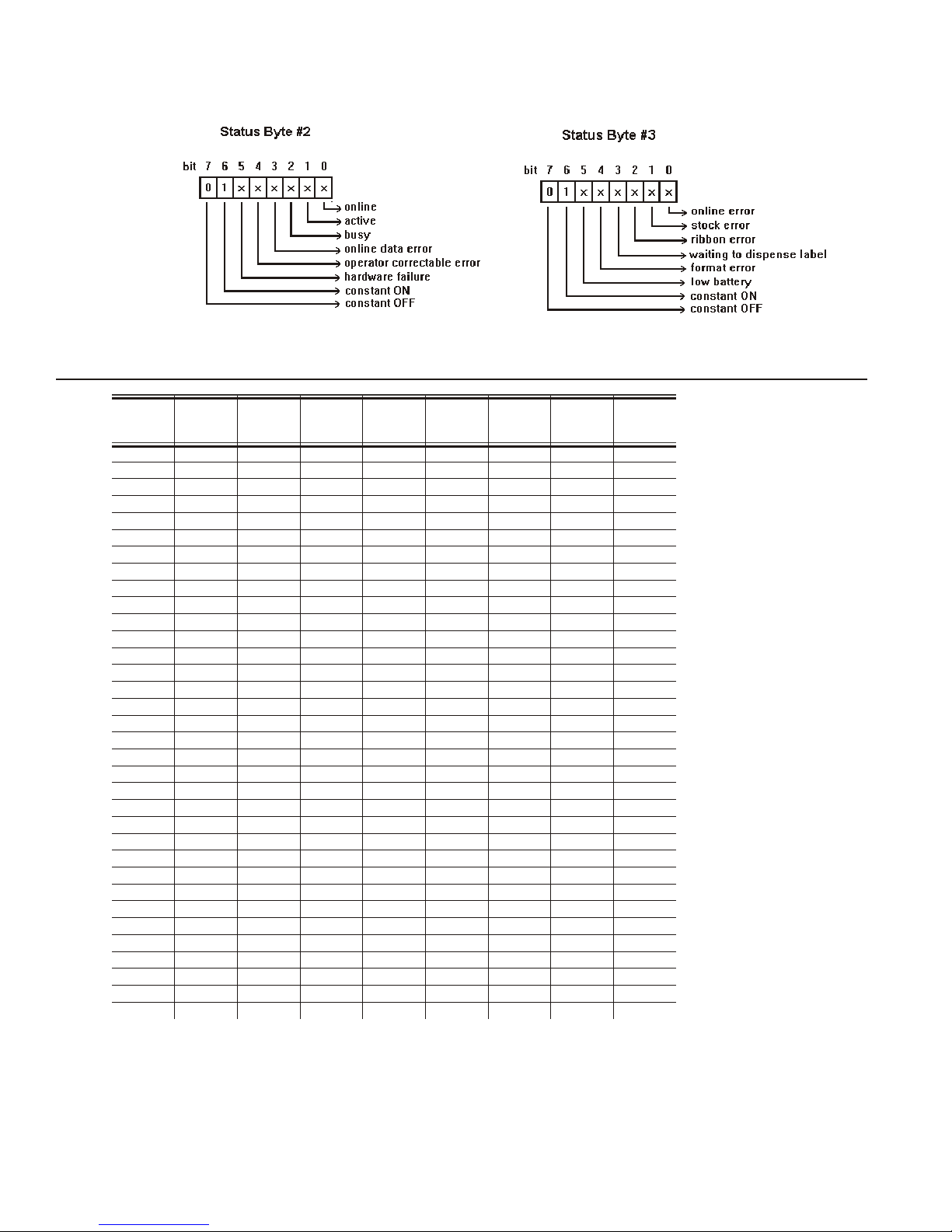
The following graphics can be used as a quick reference for the Status of Byte #2 and Byte #3.
Byte #1 is the non-printable user-defined ENQ character.
ENQ Reference Table - Byte #2
Char
@
A
B
C
D
E
F
G
H
I
J
K
L
M
N
O
P
Q
R
S
T
U
V
W
X
Y
Z
[
\
]
^
_
`
Const.
OFF
Bit 7 Bit 6 Bit 5 Bit 4 Bit 3 Bit 2 Bit 1 Bit 0
0 1 0 0 0 0 0 0
0 1 0 0 0 0 0 1
0 1 0 0 0 0 1 0
0 1 0 0 0 0 1 1
0 1 0 0 0 1 0 0
0 1 0 0 0 1 0 1
0 1 0 0 0 1 1 0
0 1 0 0 0 1 1 1
0 1 0 0 1 0 0 0
0 1 0 0 1 0 0 1
0 1 0 0 1 0 1 0
0 1 0 0 1 0 1 1
0 1 0 0 1 1 0 0
0 1 0 0 1 1 0 1
0 1 0 0 1 1 1 0
0 1 0 0 1 1 1 1
0 1 0 1 0 0 0 0
0 1 0 1 0 0 0 1
0 1 0 1 0 0 1 0
0 1 0 1 0 0 1 1
0 1 0 1 0 1 0 0
0 1 0 1 0 1 0 1
0 1 0 1 0 1 1 0
0 1 0 1 0 1 1 1
0 1 0 1 1 0 0 0
0 1 0 1 1 0 0 1
0 1 0 1 1 0 1 0
0 1 0 1 1 0 1 1
0 1 0 1 1 1 0 0
0 1 0 1 1 1 0 1
0 1 0 1 1 1 1 0
0 1 0 1 1 1 1 1
0 1 1 0 0 0 0 0
Const.ONComp.
Failure
Corr.
Error
Online
Data
Error
Busy Active Online
Note: A “1" indicates the bit is turned on. A ”0" indicates the bit is off.
7-2 STATUS POLLING
Page 85

ENQ Reference Table - Byte #2 (continued)
Char
a
b
c
d
e
f
g
h
I
j
k
l
m
n
o
p
q
r
s
t
u
v
w
x
y
z
{
|
}
~
Dec 127
Const.
OFF
Bit 7 Bit 6 Bit 5 Bit 4 Bit 3 Bit 2 Bit 1 Bit 0
Const.ONComp.
Failure
0 1 1 0 0 0 0 1
0 1 1 0 0 0 1 0
0 1 1 0 0 0 1 1
0 1 1 0 0 1 0 0
0 1 1 0 0 1 0 1
0 1 1 0 0 1 1 0
0 1 1 0 0 1 1 1
0 1 1 0 1 0 0 0
0 1 1 0 1 0 0 1
0 1 1 0 1 0 1 0
0 1 1 0 1 0 1 1
0 1 1 0 1 1 0 0
0 1 1 0 1 1 0 1
0 1 1 0 1 1 1 0
0 1 1 0 1 1 1 1
0 1 1 1 0 0 0 0
0 1 1 1 0 0 0 1
0 1 1 1 0 0 1 0
0 1 1 1 0 0 1 1
0 1 1 1 0 1 0 0
0 1 1 1 0 1 0 1
0 1 1 1 0 1 1 0
0 1 1 1 0 1 1 1
0 1 1 1 1 0 0 0
0 1 1 1 1 0 0 1
0 1 1 1 1 0 1 0
0 1 1 1 1 0 1 1
0 1 1 1 1 1 0 0
0 1 1 1 1 1 0 1
0 1 1 1 1 1 1 0
0 1 1 1 1 1 1 1
Corr.
Error
Online
Data
Error
Busy Active Online
Note: A “1" indicates the bit is turned on. A ”0" indicates the bit is off.
STATUS POLLING 7-3
Page 86

ENQ Reference Table - Byte #3
Char
@
A
B
C
D
E
F
G
H
I
J
K
L
M
N
O
P
Q
R
S
T
U
V
W
X
Y
Z
[
\
]
^
_
`
Const.
OFF
Bit 7 Bit 6 Bit 5 Bit 4 Bit 3 Bit 2 Bit 1 Bit 0
Const. ONLow
Format
Battery
0 1 0 0 0 0 0 0
0 1 0 0 0 0 0 1
0 1 0 0 0 0 1 0
0 1 0 0 0 0 1 1
0 1 0 0 0 1 0 0
0 1 0 0 0 1 0 1
0 1 0 0 0 1 1 0
0 1 0 0 0 1 1 1
0 1 0 0 1 0 0 0
0 1 0 0 1 0 0 1
0 1 0 0 1 0 1 0
0 1 0 0 1 0 1 1
0 1 0 0 1 1 0 0
0 1 0 1 1 0 0 1
0 1 0 0 1 1 1 0
0 1 0 0 1 1 1 1
0 1 0 1 0 0 0 0
0 1 0 1 0 0 0 1
0 1 0 1 0 0 1 0
0 1 0 1 0 0 1 1
0 1 0 1 0 1 0 0
0 1 0 1 0 1 0 1
0 1 0 1 0 1 1 0
0 1 0 1 0 1 1 1
0 1 0 1 1 0 0 0
0 1 0 1 1 0 0 1
0 1 0 1 1 0 1 0
0 1 0 1 1 0 1 1
0 1 0 1 1 1 0 0
0 1 0 1 1 1 0 1
0 1 0 1 1 1 1 0
0 1 0 1 1 1 1 1
0 1 1 0 0 0 0 0
Error
Waiting to
Dispense
Label
Ribbon
Fault
Stock
Fault
Online
Error
Note: A “1" indicates the bit is turned on. A ”0" indicates the bit is off.
7-4 STATUS POLLING
Page 87
ENQ Reference Table - Byte #3 (continued)
Char
a
b
c
d
e
f
g
h
I
j
k
l
m
n
o
p
q
r
s
t
u
v
w
x
y
z
{
|
}
~
Dec 127
Const.
OFF
Bit 7 Bit 6 Bit 5 Bit 4 Bit 3 Bit 2 Bit 1 Bit 0
Const. ONLow
Battery
0 1 1 0 0 0 0 1
0 1 1 0 0 0 1 0
0 1 1 0 0 0 1 1
0 1 1 0 0 1 0 0
0 1 1 0 0 1 0 1
0 1 1 0 0 1 1 0
0 1 1 0 0 1 1 1
0 1 1 0 1 0 0 0
0 1 1 0 1 0 0 1
0 1 1 0 1 0 1 0
0 1 1 0 1 0 1 1
0 1 1 0 1 1 0 0
0 1 1 0 1 1 0 1
0 1 1 0 1 1 1 0
0 1 1 0 1 1 1 1
0 1 1 1 0 0 0 0
0 1 1 1 0 0 0 1
0 1 1 1 0 0 1 0
0 1 1 1 0 0 1 1
0 1 1 1 0 1 0 0
0 1 1 1 0 1 0 1
0 1 1 1 0 1 1 0
0 1 1 1 0 1 1 1
0 1 1 1 1 0 0 0
0 1 1 1 1 0 0 1
0 1 1 1 1 0 1 0
0 1 1 1 1 0 1 1
0 1 1 1 1 1 0 0
0 1 1 1 1 1 0 1
0 1 1 1 1 1 1 0
0 1 1 1 1 1 1 1
Format
Error
Waiting to
Dispense
Label
Ribbon
Fault
Stock
Fault
Online
Error
Note: A “1" indicates the bit is turned on. A ”0" indicates the bit is off.
Job Request
A Job Request returns status information about the most recently processed print job. You can
send a job request after an ENQ or batch. You can send two levels of Job Requests:
¨ Numeric Error Codes Only (0, 1, or 2)
¨ Verbose (3 or 4)
Syntax {J,req_#}
J1. J Job Status Request
J2. req_# Type of request. Options:
0 Returns ASCII coded strings or numeric error codes
1 Returns ASCII coded strings or numeric error codes
2 Returns ASCII coded strings or numeric error codes
3 Returns the error number
4 Returns the number of labels printed in the batch
Example {J,3}
Returns the error number to the host.
STATUS POLLING 7-5
Page 88

The job response may not be immediate. If the printer has an error (out of supplies, ribbon
problem, etc.), or has insufficient memory, correct the problem and then resend the job request.
If the problem is not corrected, no response is returned. If a formatting error has occurred, the
job request returns the status. The printer must first interpret the format and batch data before
returning the response.
An ENQ can clear errors numbered less than 500. Once the error is corrected, a job request
can be sent. The printer cannot accept another job request until the error is resolved.
Job Response
The Job Response varies, depending on the type of request sent to the printer. The following
syntax is the response for a Job 0, 1,or 2 request.
Syntax {J,Status1,Status2,"FMT-1","BCH-2"}
J1. J Job Status Request
J2. Status1 These errors stop the print job. Examples include out of stock, supply faults, or data formatting
errors. These errors are numbered less than 24 on the “Job Status 0, 1, 2 Response Table,” later in
this chapter.
J3. Status2 These are errors in the syntax of the MPCL data stream. Printing does not stop, but the information
may not print properly. These errors are numbered greater than 24 on the “Job Status 0, 1, 2
Response Table,” later in this chapter.
J4. FMT-1 The format or batch number is returned.
J5. BCH-2 The format or batch number is returned.
Example {J,0,1,2}
The following is returned:
{J,8,0,"FMT-1","BCH-2"}
Indicates that a portion of the format extends off the tag in format 1, batch 2. Refer to the “Job
Status 0, 1, 2 Response Table” later in this chapter for brief explanations for J, 0, 1, 2 requests.
In the above example, refer to error 8 for an explanation.
7-6 STATUS POLLING
Page 89

The following syntax is the response for a Job 3 request. You may need to press the FEED
button before the job response is returned.
Syntax {J,"Status1 A,B","Status2 A,B,C,D,E","FMT-1","BCH-2"}
“Status1 A,B” Status1 A contains the field number, in the format or batch, where an error
was found. If the error is not in the format or batch, a “0" is returned.
Status1 B contains an error number, which represents the actual printer
error. The error numbers can be found in Chapter 8, ”Diagnostics and
Errors."
Example {J,"2,612",}
2 is the field number where an error was found. 612 is the error number, indicating that data is
missing or does not match the format definition for that field.
Note: Error numbers found in Status1 B, always have a value equal to or greater than 500.
These are considered very serious errors.
“Status2 A,B,C,D,E” contains the packet type, field type, field number, parameter, and error
number.
Status2
A- Packet Type
Status2
B- Field Type
represents the MPCLII packet that the error occurred on. The packet could
be Format (F), Batch (B), Check Digit (A), Graphic (G), or Font (W).
represents the MPCLII field that the error occurred on. If the packet has no
fields, Status2 A is replicated. If the error occurs before the field is
identified a question mark is sent. Since the batch data is variable, a D is
sent to indicate data.
Status2
C- Field Number
Status2
D- Parameter
Status2
E- Error Number
represents the field number within each packet. The packet header is the
first field and each subsequent field is indicated by the field separator.
represents the parameter within the field that the error occurred. The
numbering begins after the field identifier.
is the error that coincides with the error numbers presented in Chapter 8,
“Diagnostics and Errors.”
“FMT-1/BCH-2" The format or batch number is returned.
Note: If more than one error occurred, only the most serious error is acknowledged.
Example {J,"","F,B,4,6,33","FMT-1","BCH-2"}
Indicates that an error occurred on a bar code (B) field within a format (F) packet. The bar code
field is the fourth (4) field in the packet. The error occurred in the sixth (6) parameter of the
field. Error number 33 means the bar code density is invalid.
To clear an error, press the FEED button. An ENQ can also clear errors numbered less than 500. Once
the error is corrected, a job request can be sent. The printer cannot accept another job request until the
error is resolved.
STATUS POLLING 7-7
Page 90

The following syntax is the response for a Job 4 request.
Syntax {J,printed,total,"FMT-1","BCH-2"}
printed the number of tags or labels already printed in the batch.
total the total number of tags or labels to be printed in the current batch.
“FMT-1/BCH-2" The format or batch number is returned.
Example {J,8,25,"FMT-3","Bch-2"}
8 out of 25 tags or labels have been printed from format number 3.
Use a Job Request 4 when printing in the on-demand mode with a large number of tags or
labels from a single batch. A Job Request 4 may not be accurate if tags or labels are printed in
continuous mode, because of the response time involved. A Job Request 4 is not useful in
single ticket batches (printing 1 of 1) or multiple single ticket batches.
Note: A batch has to be printing when you send the job request. You cannot use this job
request on batches printing formats with incrementing fields.
Job Status 0, 1, 2 Response Table (Status 1 Codes)
Number Meaning
0
1
2
4
5
6
7
8
9
10
11
12
13
14
15
16
17
18
19
21
23
24
No error
Stacker fault
Supply problem
Hot printhead
Printhead open
Insufficient memory
Ribbon problem
Field ## extends off tag
Field ## has a bad font/bar code
Field ## contains invalid data
Field ## has a graphic missing
Invalid communication channel
Invalid file type
All communication channels are busy
Receive overrun error
Receive parity error
Receive framing error
Receive buffer full
Label waiting
Bad dots (verifier detected a failure)
Low battery
Memory configuration packet error
Numbers 25 through 50 are not currently in use.
7-8 STATUS POLLING
Page 91

Job Status 0, 1, 2 Response Table (Status 2 Codes)
Number Meaning
51
52
53
54
55
56
57
58
59
60
61
62
63
64
65
66
67
68
69
70
71
72
73
74
75
80
81
82
83
84
Invalid command
Invalid separator value
Graphic not found
Format for batch not found
Quantity/Multiples out-of-range
Name descriptor too long
Invalid cut value
Invalid number-of-parts value
Invalid orientation value
Invalid thickness value
Invalid text field
Invalid bar code field
Data string too long
Invalid data field
Row greater than stock length
Row greater than format length
Column greater than printhead width
Column greater than format width
Invalid label length
Invalid label width
Invalid increment/decrement value
Identifier out-of-range
No field to create format
Stop location of a line is out of range
Syntax error
Can’t use offline format for online batch
Can’t queue graphic batch
Can’t store online format
Can’t queue online batch
Can’t queue online clear command
STATUS POLLING 7-9
Page 92

7-10 STATUS POLLING
Page 93

DIAGNOSTICS AND ERRORS 8
This chapter explains how to
¨
print test labels
¨
reset the printer
¨
call Technical Support.
Before you call Service, print a test label. The label contains information to help
diagnose mechanical and setup problems.
This chapter also provides explanations of your printer’s errors. The errors are
classified by type and are listed in order. If you have trouble loading supplies or
performing maintenance, refer to the Equipment Manual.
Some errors numbered 400-438 and 500-574 are internal software errors.
Errors numbered 703-758 are supply errors. Follow the directions provided with
the error description to correct the problem. Errors numbered 900-999 are Hard
Printer Failures. If you cannot clear an error, turn off the printer, wait several
seconds and then turn on the printer. Call Technical Support if you receive any
error message not listed in this chapter.
If a formatting error occurs, the label prints; but data may be missing. Correct
the format or batch and resend them to the printer.
DIAGNOSTICS AND ERRORS 8-1
Page 94
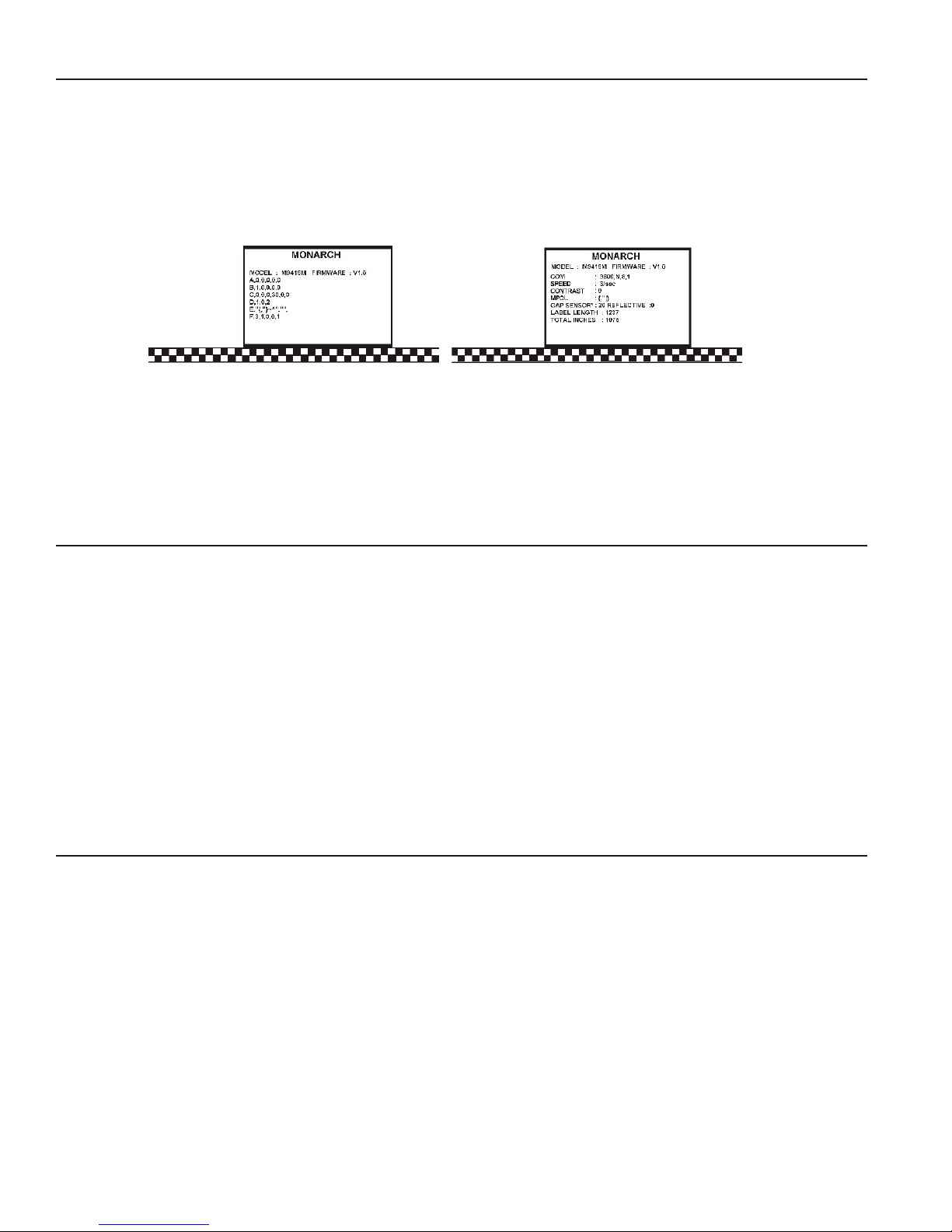
Printing a Test Label
1. Turn off the printer.
2. Press and hold the FEED button while turning on the printer.
3. Release the FEED button when the LED is flashing orange and the printer starts advancing
lines.
The test labels print. The first label shows the model number and the printer’s configuration
by packet (A-F). See Chapter 2, “Configuring the Printer,” for more information.
The second label shows the software version, communication settings, speed, contrast, gap
sensor setting, label length, and total number of inches printed.
Reading a Test Label
The first test label shows the model number, software version, and the printer’s configuration by
packet. See Chapter 2, “Configuring the Printer” for more information about the printer’s
configuration.
The second test label shows the model number, software version, total number of inches
printed, voltage, print contrast, printhead resistance, number of bad dots, and memory. In the
example above:
¨ The printer has printed 119 inches of regular supplies.
¨ The printer has printed no linerless (high-energy) supplies.
¨ No options are set
¨ CONTRAST POT does not apply.
Using Data Dump
After printing test labels, this printer is in “data dump mode.” To use data dump mode:
1. Turn off the printer.
2. Press and hold the FEED button while turning on the printer.
3. Release the FEED button when the printer starts advancing lines.
The test labels print.
Your printer is now in data dump mode.
4. Download the data stream you wish to “dump” (print out on a label).
8-2 DIAGNOSTICS AND ERRORS
Page 95

5. The data stream prints out automatically when there is enough data to fill a label. Press the
FEED button to print any remaining data on another label.
,"06/11/94" p }0 10
D AD
1111" p o2,"G111111" p 03,"Smith" p 04, “12345678" p 05
3,"CHECKER ID: " p }0{B,1,N,1 p 01,”G111111
D D
200,100,0,1,2,1,B,L,0,3 p OC,330,20,0,1,1,1,B,L,0,
D
0,100,0,1,1,1,B,L,0,3,"DATE RECEIVED:" p OT,5,8,V,
D
“VIN #:” p OT,4,17,V,260,130,0,1,2,B,L,0,3 p OC,33
D D
,160,0,1,2,1,B,L,0,3 p OC,330,130,0,1,1,1,B,L,0,3,
D
C,330,160,0,1,1,1,B,L,0,3,"OWNER:" p OT,3,15,F,260
D
,3,3,2,B,L,0,3 p 08,2,9,V,330,220,4,11,080,8,L,3 p 0
D D
{F,1,A,R,E,400,400,"WINDSHIE" p OT,1,9,V,310,340,0
D
6. Download another data stream to dump or press the FEED button to exit data dump mode.
Resetting Printers
Sometimes the printer receives mixed signals and loses its ability to communicate. If this
happens, reset the printer and attempt communication again. To reset the printer, turn off the
printer, wait 15 seconds, and turn it back on.
When you turn off the printer, all the information set through the online configuration packets
(A-F) is saved. See the sections in Chapter 2, “Configuring the Printer,” for more information
about each packet.
If You Receive an Error Message
Any time you receive a message that is not described in this manual, or the recommended
action does not solve the problem, call Technical Support. Some errors are the result of
communication problems. In this case, reset your printer and reboot your computer. If you
change any of the online configuration packets, resend the format packet to the printer, so the
configuration changes take effect.
If the PC and Printer Are Not Communicating
If your PC is having trouble communicating with your printer, follow these steps:
¨ Check any messages that occur at the printer and at the computer. See the following error
message listing in this chapter for more information.
¨ Make sure you are using the correct printer cable.
¨ Make sure the cable is plugged into the correct port on the computer.
¨ Compare your printer’s communications settings (especially flow control) with the settings on
your PC. Your printer and PC communications should match. Print a test label to identify
the printer’s communication settings.
¨ Make sure the printer is online (ready to receive data).
If all of the above are correct, reset your printer. Try the function again. If you still can not
establish communications, call Technical Support.
DIAGNOSTICS AND ERRORS 8-3
Page 96

Calling Technical Support
Technical support representatives are available Monday through Friday during regular business
hours. Follow these steps before you call:
1. Make sure your PC and printer are properly connected.
2. Record any error messages that occurred.
3. Recreate the problem, if you can.
4. Check your port settings. Your problem may be corrected simply by changing the
communication settings.
5. List any changes that have recently been made to the system. Try to record what you were
doing when the problem occurred.
6. Reset your printer. For information on resetting your printer, see "Resetting Printers."
7. Reboot your computer. Refer to your computer documentation for specific instructions.
8. Print a test label, see “Printing a Test Label” for more information.
Have the following information ready before you call: computer brand name and model, version
of DOS, printer model, other peripheral devices on your system, support agreement, contract
number, or invoice information, customer number, and printer serial number.
Additional Diagnostics Information
For detailed printer diagnostics information, refer to the Equipment Manual. See Chapter 7,
“Status Polling,” for information on requesting printer and job status. See the following error
message listing in this chapter for more information.
Data Errors
Errors 001 to 499 are data errors. These errors are returned in response to a J,3 request. See
Chapter 7, “Status Polling,” for more information. A data error indicates that incorrect data was
received from the host, causing the printer to ignore the entire print job. After checking the
packet and correcting the problem, transmit the print job again.
The following is a list of data errors. These errors occur because data in the format, batch,
check digit, font, or graphic packet is invalid.
Format Errors
Error
Code
001
002
Description
Packet ID number must be 1 to 999.
Name must be 1 to 8 characters (excluding non-printable control characters) inside
quotes.
003
004 Supply length is invalid. See “Defining the Format Header” in Chapter 3 for valid
005 Supply width is invalid. See “Defining the Format Header” in Chapter 3 for valid
8-4 DIAGNOSTICS AND ERRORS
Action must be A (add) or C (clear).
lengths.
widths.
Page 97

006
Storage device must be F (Flash), M (Memory Card), R (volatile RAM), or T
(temporary for graphics). The 9416 memory card only stores fonts. The 9416XL
memory card stores formats, graphics, and fonts.
007
Unit of measure must be E (English), M (Metric), or G (Dots). See “Defining the
Format Header” in Chapter 3 for more information.
010
011
Field ID number is outside the range 0 to 999.
Field length exceeds 2710.
012 Row field position is greater than the maximum stock dimension. See “Defining Text
Fields” in Chapter 3 for valid row lengths.
013 Column field position is greater than the maximum stock dimension. See “Defining
Text Fields” in Chapter 3 for valid column widths.
014
Font style must be 1, 2, 3, 4, 5, 6, 10, 11, 15, 16, 17, 18, or 50. See “Defining Text
Fields” in Chapter 3 or Appendix B, “Fonts,” for more information.
015
Character rotation must be 0 (0 degree), 1 (90 degree),
2 (180 degree), or 3 (270 degree). See “Defining Text Fields” in Chapter 3 for more
information.
016
Field rotation must be 0 (0 degree), 1 (90 degree), 2 (180 degree), or 3 (270 degree).
See “Defining Text Fields” in Chapter 3 for more information.
017
Field restriction must be V (variable) or F (fixed).
018
020
021
022
023
024
025
030
Code page/symbol set selection defined in the field must be 0 (Internal), 1 (ANSI),
102 (Unicode), 437 (DOS Page 437), 850 (DOS Page 850), 852 (Latin 2), 855
(Russian), 857 (Turkish), 860 (Portuguese), 1250 (Latin 2), 1251 (Cyrillic), 1252 (Latin
1), 1253 (Greek), 1254 (Turkish), 1255 (Hebrew), 1256 (Arabic), 1257 (Baltic), or 1258
(Vietnamese). See “Defining Text Fields” in Chapter 3 for more information.
Vertical magnification must be 1 to 7 for standard printer fonts or 4 to 255 (point size)
for the scalable or downloaded TrueType fonts.
Horizontal magnification must be 1 to 7 or 4 to 255 (point size) for the scalable or
downloaded TrueType fonts.
Color must be A, B, D, E, F , N, O, R, S, T, or W. See “Defining Text Fields” in Chapter
3 for more information.
Intercharacter gap must be 0 to 99 dots.
Field justification must be B (balanced), C (centered), E (end),
L (left), or R (right). See “Defining Text Fields” in Chapter 3 for more information.
String length is outside the range 0 to 2710.
Bar code height must be at least 20 (English), 51 (Metric), 40 (203 Dots), 60 (300
dots), or is not within the supply dimensions.
DIAGNOSTICS AND ERRORS 8-5
Page 98

031 Human readable option must be
0 default
1 no CD or NS
5 NS at bottom, no CD
6 CD at bottom, no NS
7 CD and NS at bottom
8 no text
032 Bar code type is invalid. See “Defining Bar Code Fields” in Chapter 3 for valid
options.
033 Bar code density is invalid. See “Defining Bar Code Fields” in Chapter 3 for the bar
code density chart.
040
041
Line thickness must be 0 to 99 dots.
Line direction must be 0, 90, 180, or 270.
042 End row is invalid. Line segment or box end row is defined outside of printable area.
043 End column is invalid. Line segment or box end column is defined outside of printable
area.
044 Dot pattern for line or box must be “”.
045 Line length is defined beyond the maximum length. See “Defining Line Fields” in
Chapter 3 for valid lengths.
046
051
Line type must be S (segment) or V (vector).
Imaging mode in the graphic header must be 0.
Batch Errors
Error
Code
101 The format referenced by batch is not in memory.
Description
102
104
105
106
107
108
109
8-6 DIAGNOSTICS AND ERRORS
Print quantity is outside the range 0 to 32,000.
Batch mode must be N (new) or U (update).
Batch separator in a batch control field must be 0 (Off).
Print multiple is outside the range 1 to 32,000.
Cut multiple is outside the range 0 to 999. Only valid for printers with a knife.
Multiple part supply is outside the range 1 to 5.
Cut type is outside the range 0 to 5. Only valid for printers with a knife.
Page 99

Option Errors
Error
Code
200
201
202
203
204
205
206
207
208
209
210
Description
Option number must be 1, 4, 30, 31, 42, 50, 51, 52, 60, or 61.
Copy length is outside the range 0 to 2710.
Copy start position must be 1 to 2710.
Destination start position must be 1 to 2710.
Source field must be 0 to 999.
Copy type must be 1 (copy after rules) or 2 (copy before rules).
Increment/Decrement selection must be I (increment) or
D (decrement).
Incrementing start position must be 0 to 2710.
Incrementing end position must be 0 to 2710.
The incrementing amount must be 0 to 999.
Security value for a PDF-417 bar code must be 0 to 8. Correct the value and resend
the format to the printer.
211
212
213
214
215
216
217
218
219
220
221
222
Narrow element value is less than 1 or greater than 99. Correct the value and resend
the format to the printer.
Wide element value is less than 1 or greater than 99. Correct the value and resend
the format to the printer.
Dimension must be 1 to 30 for a column or 3 to 90 for a row on a PDF417 bar code.
Truncation code must be S (standard) or T (truncated bar code).
Aspect code must be C (columns) or R (rows).
Option definition must be S (set) or T (template).
Input device must be D (Default), H (Host), K (Keyboard), N (None), or S (Scanner).
Pad direction must be L (from left) or R (from right).
Pad character is outside the range 0 to 255.
Check digit selection must be G to generate check digit.
Primary or secondary price format is outside the range 1 to 16.
Data type restriction is outside the range of 1 to 6.
223 Option is not valid for the field.
224
Bar code intercharacter gap must be 0 to 99 dots. (This is also known as the
additional character gap when using Option 50, Defining Bar Code Densities.)
DIAGNOSTICS AND ERRORS 8-7
Page 100

Online Configuration Errors
Error
Code
251
252
253
254
255
256
257
258
259
260
261
Description
Power up mode must be 0 (online).
Language selection must be 0 (English).
Batch separator must be 0 (off).
Slash zero selection must be 0 (standard zero).
Supply type must be 0 (black mark), 1 (die cut), or 2 (continuous/non-indexed).
Ribbon selection must be 0 (thermal direct) or 1 (thermal transfer).
Feed mode must be 0 (continuous) or 1 (on-demand).
Supply position must be -300 to 300 dots.
Contrast adjustment must be -390 to 156 dots.
Print adjustment (position) must be -99 to 99 dots.
Margin adjustment (position) must be -99 to 99 dots.
262
263
264
265
266
267
268
269
270
Speed adjustment must be 0 (default), 20 (2.0 ips), 30 (3.0 ips), 40 (4.0 ips), or 50
(5.0 ips).
Primary monetary symbol must be 0 (None), 1 (Dollar), 2 (Pound), 3 (Yen), 4
(Deutsche Mark), 5 (Franc), 6 (Peseta), 7 (Lira), 8 (Krona), 9 (Markka), 10 (Schilling),
11 (Rupee), 12 (Ruble), 13 (Won), 14 (Baht), 15 (Yuan), or 16 (Eurodollar).
Secondary symbol selection must be 0 (none) or 1 (print secondary sign).
Monetary decimal places must be 0 to 3.
Character string length in the control characters packet must be 5 (MPCL control
characters) or 7 (ENQ/IMD command character).
Baud rate selection must be 0 (1200), 1 (2400), 2 (4800), 3 (9600), 4 (19200), or 5
(38400). Resend the communication settings packet.
Word length selection must be 0 (7 bits), or 1 (8 bits). Resend the communication
settings packet.
Stop bits selection must be 0 (1 bit), or 1 (2 bits). Resend the communication settings
packet.
Parity selection must be 0 (none), 1 (odd), or 2 (even). Resend the communication
settings packet.
271
Flow control selection must be 0 (none), 1 (DTR), 2 (CTS/RTS), or 3 (XON/XOFF).
Resend the communication settings packet.
8-8 DIAGNOSTICS AND ERRORS
 Loading...