


Bedienungsanleitung / Handbuch / Datenblatt
Sie benötigen einen Reparaturservice für Ihren Etikettendrucker
oder suchen eine leicht zu bedienende Etikettensoftware?
Wir helfen Ihnen gerne weiter.
Ihr Partner für industrielle Kennzeichnungslösungen
Drucksysteme Janz & Raschke GmbH
Röntgenstraße 1
D-22335 Hamburg
Telefon +49(0)40 – 840 509 0
Telefax +49(0)40 – 840 509 29
kontakt@jrdrucksysteme.de
www.jrdrucksysteme.de

Bedienungsanleitung / Handbuch / Datenblatt
Maßgeschneiderte Lösungen für den Etikettendruck und die Warenkennzeichnung
Seit unserer Gründung im Jahr 1997, sind wir erfolgreich als Partner namhafter Hersteller und als
Systemintegrator im Bereich der industriellen Kennzeichnung tätig.
Unser Motto lautet:
So flexibel wie möglich und so maßgeschneidert wie nötig.
Ich stehe mit meinem Namen für eine persönliche und
kompetente Beratung. Wir hören Ihnen zu und stellen mit Ihnen
eine Lösung zusammen, die Ihren individuellen Anforderungen
entspricht. Für Sie entwickeln unsere erfahrenen Techniker und
Ingenieure neben Etikettiermaschinen, maßgeschneiderte
Komplettlösungen inklusive Produkthandling,
Automatisierungstechnik und Softwarelösung mit Anbindung an
Ihr Warenwirtschaftssystem.
Ich freue mich von Ihnen zu hören.
Bis dahin grüßt Sie
Jörn Janz
Hier finden Sie Ihren Ansprechpartner:
http://www.jrdrucksysteme.de/kontakt/

9416TTXLI Service Manual Rev. A ©2008 Avery Dennison Corp. All rights reserved.
SERVICE
MANUAL
M09416 ®T
T
X
LI
®
THERMAL TRANSFER / DIRECT THERMAL
BAR CODE PRINTER

M09416 ® TTXLI ®
Thermal Transfer Printer
i
1. FUNDAMENTAL OF THE SYSTEM ........................................................................ 1
1.1. Overview ....................................................................................................... 1
1.1.1. Front View.......................................................................................................... 1
1.1.2. Rear View........................................................................................................... 2
1.2. LED ................................................................................................................ 3
1. 3. Button........................................................................................................... 3
2. REPLACE IMPORTANT PARTS ............................................................................. 6
2.1. Replacing Top Cover.................................................................................... 6
2.2. Replacing Top Inner Cover.......................................................................... 8
2.3. Replacing Lower Cover ............................................................................. 10
2.4. Replacing Main Board................................................................................ 12
2.5. Replacing Platen Assembly....................................................................... 13
2.6. Replacing the Stepping Motor Bracket / Metal Assembly and Stepping
Motor .................................................................................................................. 14
2.7. Replacing Label Guide & Gap Sensor Assembly .................................... 16
2.8. Replacing Black Mark Sensor Assembly ................................................. 18
2.9. Replacing Print Head Assembly................................................................ 19
2.10. Replacing Head Open Micro Switch ....................................................... 20
2.11. Replacing Ribbon Motor and Ribbon Sensor ........................................ 22
2.12. Replacing Feed Button and Feed Button PCB....................................... 24
2.13. Install SD Memory Card ........................................................................... 25
2.14. Install Peel Off Module (Option) .............................................................. 26
2.15. Loading the Label in Peel-off Mode ........................................................ 28
2.16. Install Cutter Module (Option) ................................................................. 30
2.17. Loading Label in Cutter Mode ................................................................. 34
3. Power on Utilities ................................................................................................. 35
3.1 Ribbon and Gap/Black Mark Sensor Calibration ...................................... 35
3.2 Gap/Black Mark Calibration
Self-test ...................................................... 37
3.3 Printer Initialization ..................................................................................... 38
3.4 Black Mark Sensor Calibration................................................................... 39
3.5 Gap Sensor Calibration .............................................................................. 39
4. GAP AND BLACK MARK SENSOR SELECTION ................................................ 40
5. BIOS Update.......................................................................................................... 40
6. TROUBLESHOOTING ........................................................................................... 41
7. MAINTENANCE..................................................................................................... 46
8. PARTS LIST........................................................................................................... 48
8.1 Cover ............................................................................................................ 48

M09416 ® TTXLI ®
Thermal Transfer Printer
ii
8.2 Cover drawing ............................................................................................. 49
8.3 Main Board................................................................................................... 50
8.4 Main Board drawing .................................................................................... 51
8.5 Top Inner Cover ........................................................................................... 52
8.6 Top Inner Cover drawing ............................................................................ 53
8.7 Lower Inner Cover....................................................................................... 54
8.8 Lower Inner Cover drawing ........................................................................ 55
8.9 Ribbon Mechanism Assembly.................................................................... 56
8.10 Lower Inner Cover - Bottom ..................................................................... 57
8.11 Lower Inner Cover - Bottom drawing....................................................... 58
8.12 Stepping Motor Assembly ........................................................................ 59
8.13 Stepping Motor Assembly drawing.......................................................... 60
8.14 Option and accessories............................................................................ 61
8.15 Option and accessories drawing ............................................................. 61
UPDATE HISTORY .................................................................................................... 62
M09416 ® TTXLI ®
Thermal Transfer Printer
1
1. FUNDAMENTAL OF THE SYSTEM
1.1. Overview
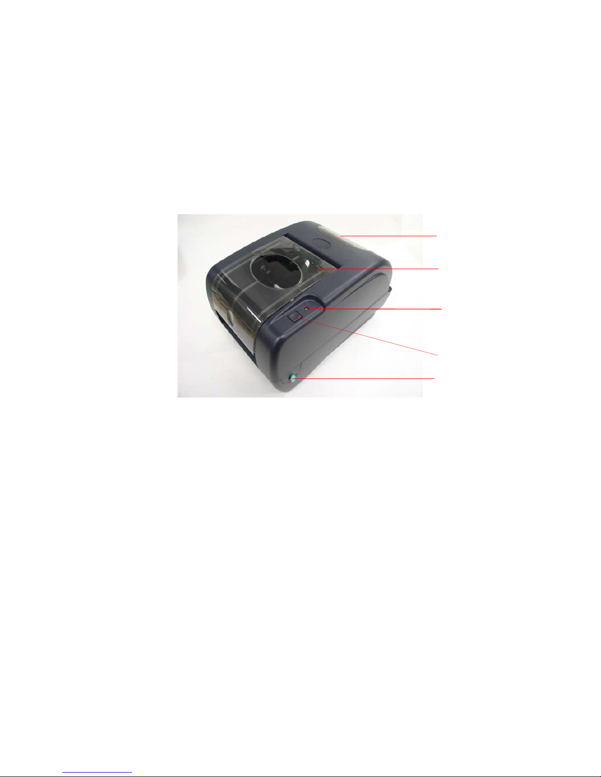
1.1.1. Front View
Fig. 1.1.1 Front View
Top Cover Open Lever
Ribbon Access Window
Feed Button
LED Indicator
Label Roll Capacity
View Window
M09416 ® TTXLI ®
Thermal Transfer Printer
2
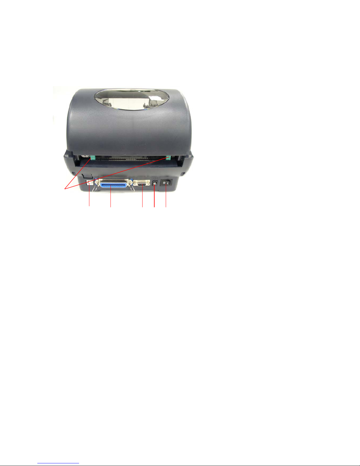
1.1.2. Rear View
Fig. 1.1.2 Rear View
1. USB Interface
2. Centronics Interface
3. RS-232 Interface
4. Power Jack
5. Power Switch
6. Rear Paper Guide
1 2 3 4 5
6

M09416 ® TTXLI ®
Thermal Transfer Printer
3
1.2. LED
LED Color Description
Green/ Solid
This illuminates that the power is on and the device is
ready to use.
Green/ Flash This illuminates that the system is downloading data
from PC to memory and the printer is paused.
Amber
This illuminates that the system is clearing data from
printer.
Red / Solid This illuminates printer head open, cutter error.
Red / Flash This illuminates a printing error, such as paper empty,
paper jam, ribbon empty, or memory error etc.
1. 3. Button
Feed
Press the button when the LED is green.
It feeds the label to the beginning of the next label.
Pause
Press the feed button during printing
The printing job is suspended.
Ribbon Sensor and
Gap/Black Mark
Sensor Calibration
1. Turn off the power switch.
2. Hold on the button then turn on the power switch.
3 Release the button when LED becomes red and blinking.
(Any red will do during the 5 blinks).
It will calibrate the ribbon sensor and gap/black
mark sensor sensitivity.
The LED color will be changed as following order
Amber red (5 blinks) amber (5 blinks)
green (5 blinks) green/amber (5 blinks)
red/amber (5 blinks) solid green

M09416 ® TTXLI ®
Thermal Transfer Printer
4
Gap/Black Mark
Sensor Calibration,
Label Length
Measurement, Self-
Test
1.Turn off the power switch.
2. Hold on the button then turn on the power switch.
3. Release the button when LED becomes amber and
blinking. (Any amber will do during the 5 blinks).
The LED color will be changed as following order.
Amber red (5 blinks) amber (5 blinks)
green (5 blinks) green/amber (5 blinks)
red/amber (5 blinks) solid green
It calibrates the sensor and measures the label
length and prints internal settings.
Printer Initialization
1. Turn off the power switch.
2. Hold on the button then turn on the power switch.
3. Release the button when LED turns green after 5 amber
blinks. (Any green will do during the 5 blinks).
The LED color will be changed as following:
Amber red (5 blinks) amber (5 blinks)
green (5 blinks) green/amber (5 blinks)
red/amber (5 blinks) solid green
Note:
Always do gap/black mark sensor calibration
after
printer initialization.
Force Black Mark
Sensor Calibration
1. Turn off the power switch.
2. Hold on the button then turn on the power switch.
3. Release the button when LED turns green/amber after 5
green blinks.
(Any green/amber will do during the 5
blinks).
The LED color will be changed as following:
Amber red (5 blinks) amber (5 blinks)
green (5 blinks) green/amber (5 blinks)
red/amber (5 blinks) solid green

M09416 ® TTXLI ®
Thermal Transfer Printer
5
Force Gap Sensor
Calibration
1. Turn off the power switch.
2. Hold on the button then turn on the power switch.
3. Release the button when LED turns red/amber after 5
green/amber blinks.
(Any red/amber will do during the 5
blinks).
The LED color will be changed as following:
Amber red (5 blinks) amber (5 blinks)
green (5 blinks) green/amber (5 blinks)
red/amber (5 blinks) solid green
M09416 ® TTXLI ®
Thermal Transfer Printer
6
2. REPLACE IMPORTANT PARTS
Please turn off the power switch and unplug the power adapter before replacing parts.
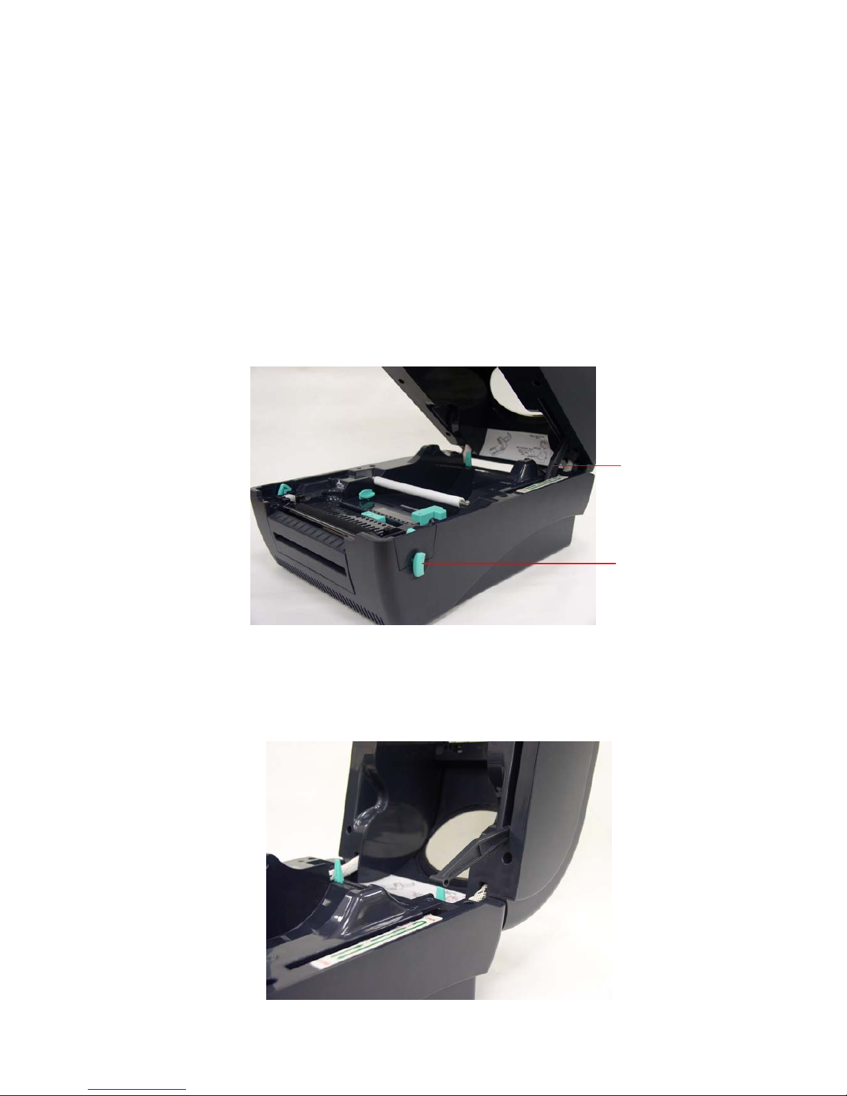
2.1. Replacing Top Cover
1. Open the printer top cover by pushing the top cover open levers to the
paper outlet direction. The top cover support will hold the printer top cover.
2. Open the top cover to the ultimate open angle. Push the top cover support to
the communication port direction to disconnect the separate the lower inner
cover and top cover support.
Top cover support
Top cover open
lever

M09416 ® TTXLI ®
Thermal Transfer Printer
7
3. Remove the 6 screws in the top inner cover.
4. Disconnect the harness from the Feed button PCB. Replace the top cover.
5. Reassemble parts in reverse order following the procedures above
Screws
Screws
M09416 ® TTXLI ®
Thermal Transfer Printer
8
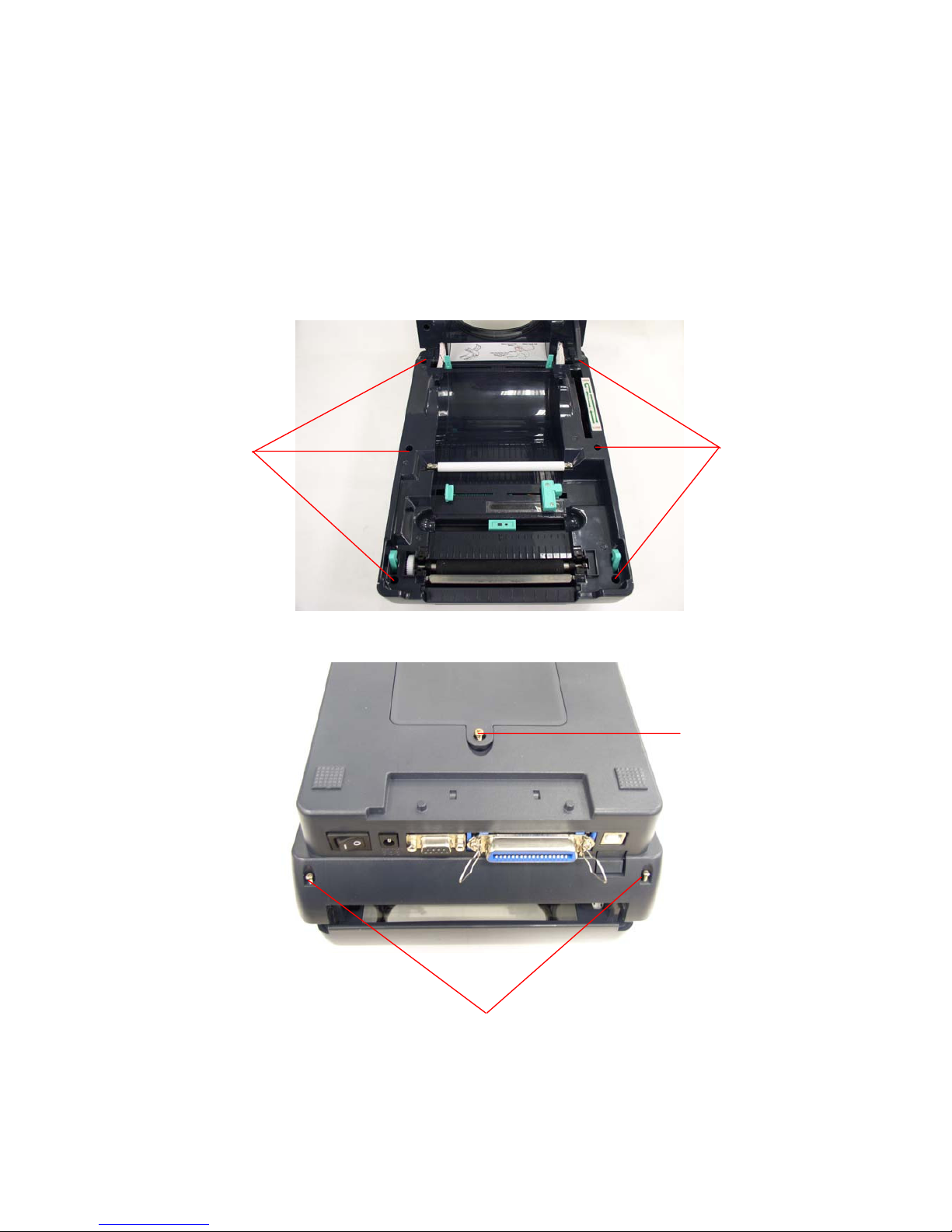
2.2. Replacing Top Inner Cover
1. Refer 3.1 to remove the top cover.
2. Remove the 6 screws of lower inner cover. Turn the printer upside down, and
remove the 2 screws of hinge holder, 1 screw of memory card cover.
3. Disconnect all the harnesses from Main Board. Lift up the lower inner cover.
2 screws of hinge holder
Screw of memory
card cover
Screws
Screws

M09416 ® TTXLI ®
Thermal Transfer Printer
9
Turn the lower inner cover upside down, and remove the 6 screws of lower
inner cover and hinge holders.
4. Replace the top inner cover.
5. Reassemble in reverse order following the procedures above

M09416 ® TTXLI ®
Thermal Transfer Printer
10
2.3. Replacing Lower Cover
1. Refer to 3.1 to open the top cover.
2. Remove the 6 screws of lower inner cover. Turn the printer upside down, and
remove the 2 screws of hinge holder, 1 screw of memory card cover.
3. Disconnect all the harnesses from Main Board. Lift up the lower inner cover.
4. Replace lower cover.
Screws
Screws
2 screws of hinge holder
Screw of memory
card cover

M09416 ® TTXLI ®
Thermal Transfer Printer
11
5. Reassemble in reverse order following the procedures above
M09416 ® TTXLI ®
Thermal Transfer Printer
12
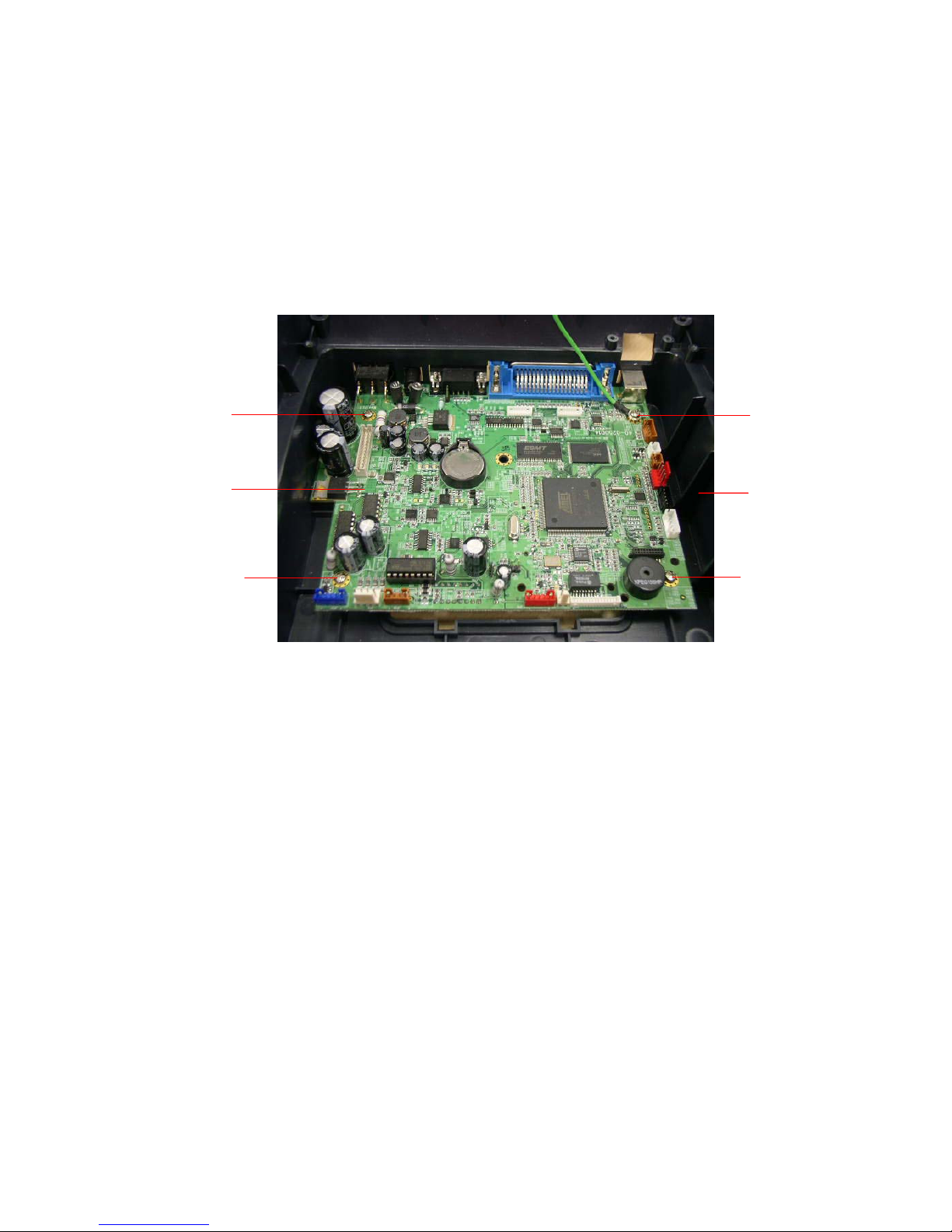
2.4. Replacing Main Board
1. Please refer to 3.3 for disassembling the LOWER COVER and LOWER inner
cover.
2. Disconnect all harnesses.
3. Remove 4 screws on the main board.
4. Replace the main board/lower inner cover.
5. Reassemble parts in reverse order following the procedures above
Screw
Screw
Screw
Screw
Lower Cover
Main Board
M09416 ® TTXLI ®
Thermal Transfer Printer
13
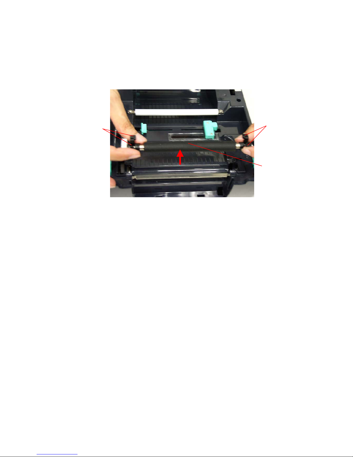
2.5. Replacing Platen Assembly
1. Squeeze two sides of platen assembly and take it out.
2. Replace a platen.
3. Reassemble it in reverse order following the procedures above
Squeeze Here
Platen
Squeeze Here
M09416 ® TTXLI ®
Thermal Transfer Printer
14
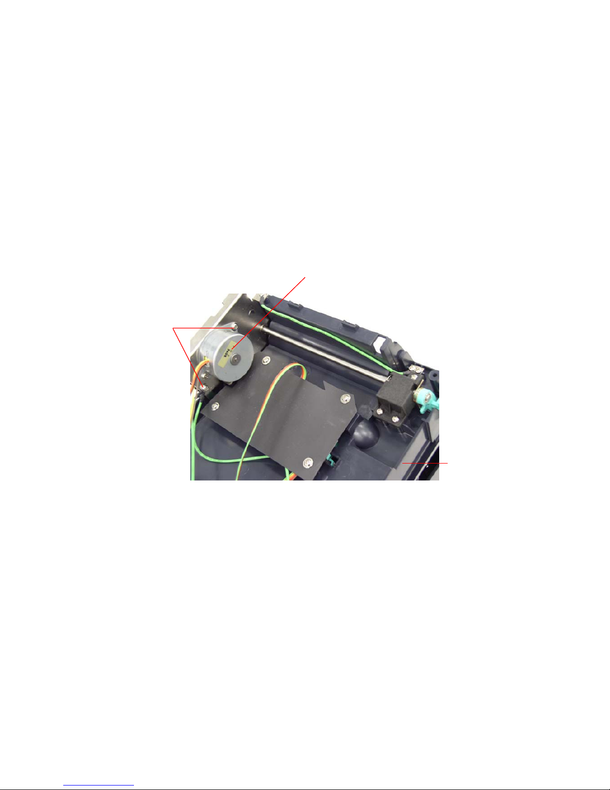
2.6. Replacing the Stepping Motor Bracket / Metal Assembly
and Stepping Motor
1. Please refer to 3.1 for disassembling the lower cover and lower inner cover.
2. Disconnect all hardness.
3. Turn the lower inner cover upside down.
4. Remove 2 screws that fixed the stepping motor on the bracket
5. Remove the stepping motor.
6. Use a screwdriver to screw off 8 screws of the stepping motor bracket /
metal assembly.
Screws
Motor
Lower inner cover

M09416 ® TTXLI ®
Thermal Transfer Printer
15
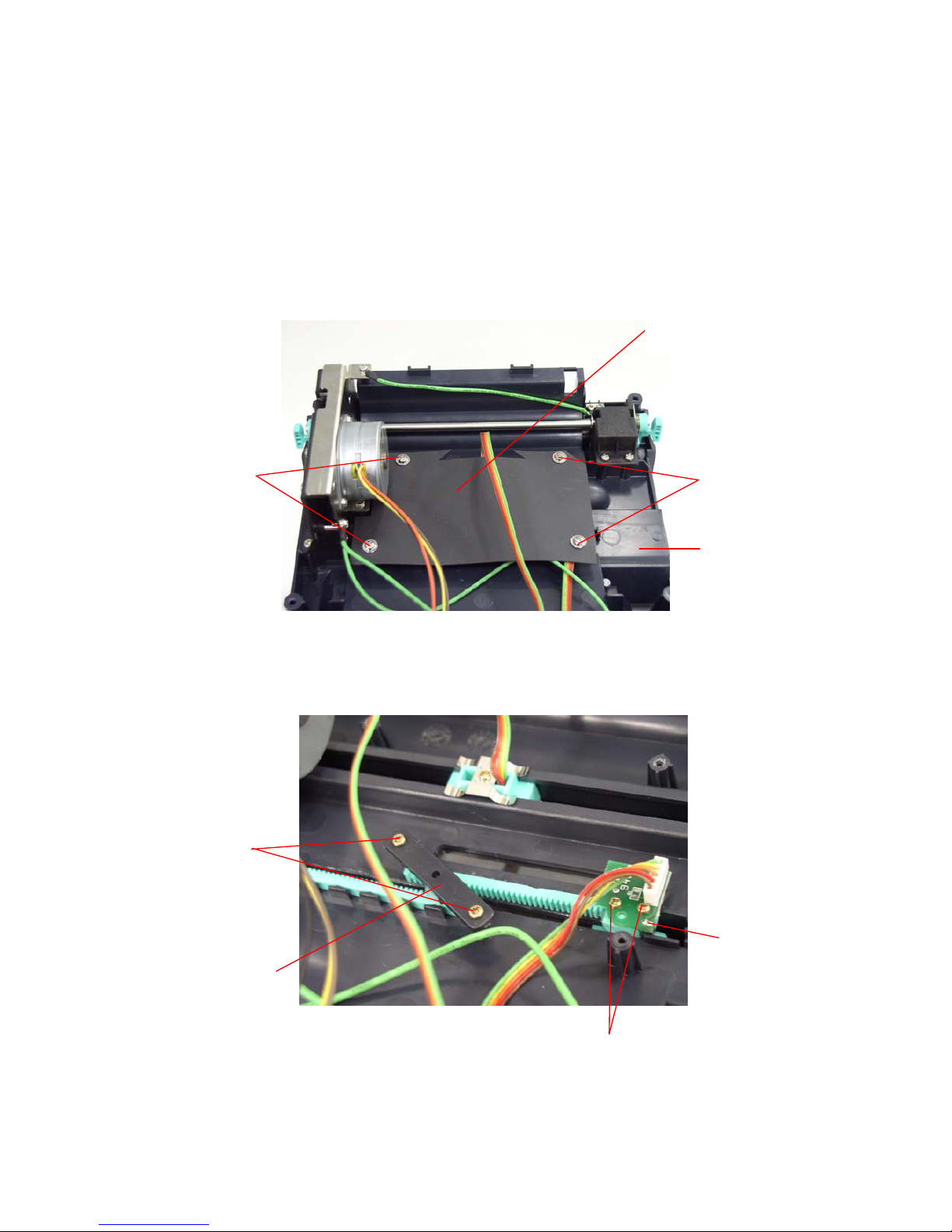
7. Remove the stepping motor bracket / metal assembly.
8. Reassemble parts in reverse order following the procedures above
Screws
Screws
M09416 ® TTXLI ®
Thermal Transfer Printer
16
2.7. Replacing Label Guide & Gap Sensor Assembly
1. Please refer to 3.1 for disassembling the lower cover and lower inner cover.
2. Disconnect all the hardness.
3. Turn the lower inner cover upside down.
4. Screws off 4 screws and remove the plastic laminate.
5. Screws off 2 screws to remove the white label guide rack fixing plate
6. Remove 2 screws from a gap sensor PCB then remove the gap sensor PCB.
7. Turn over the lower inner cover.
Screws
Screws
Label Guide
Rack Fixing
Plate
Screw
Gap Sensor
PCB
Plastic Laminate
Lower inner cover
Screws
 Loading...