

Page 1

05/09 Rev. 5.02-01 USER MANUAL
AP 4.4 – AP5.4
Setup & Operation
Installing the Printer ......................................2
Unpacking the printer ................................ 2
Carrying the Printer ................................... 2
Check the Delivery ....................................3
Removing the Transportation Lock ........... 6
Product Description .......................................7
Operating Parts AP4.4 / AP5.4 basic ....... 7
Operating parts AP5.4 Dispenser /
Internal Rewinder ......................................9
Modes of Operation AP5.4 Dispenser /
Internal Rewinder ....................................11
Arrangement of the Connections ...........12
Warning Signs at the Printer ................... 14
Control Panel (Display) ........................... 15
Operating State ....................................... 16
Basic Operating Procedures .......................18
Connecting the Printer .............................18
Setting the Interface .................................19
Activate/Deactivate Internal Rewinder .....19
Activate/Deactivate Dispenser .................20
Configure Dispenser ...............................21
Operation in Offline Mode ........................21
Operation in Online Mode ........................22
Creating a Print job ..................................23
Transferring a Print Job ...........................23
Using CF Cards (AP5.4) .........................24
Setting the Realtime Clock (AP5.4) .........26
Reading out real time with Easy-Plug
(AP 5.4) .................................................... 26
Page 2

05/09 Rev. 5.02-01 USER MANUAL Setup & Operation
AP 4.4 – AP5.4
2
Installing the Printer
Unpacking the printer
1. Remove all loose objects from the packaging.
2. Carefully lift the printer together with the polystyrene cushions out of the
box. Have a second person keep hold of the box while you remove the
printer.
[1] AP 5.4 in the original packaging.
3. Remove the polystyrene cushions and plastic wrap from the printer. Having someone else help you with this will also make it easier!
4. Place the printer on an even surface.
Carrying the Printer
One person can easily carry the AP4.4/5.4 because it only weighs 14kg.
« To carry the printer, grip the baseplate from the front and rear [2].
[2] When lifting the printer, grip under the baseplate!
Packaging ¯ Please retain the original packaging for later use when transporting the
printer!
CAUTION! - Observe the following to avoid damaging the printer:
« Do not lift the printer by holding the plastic parts on the front and rear.
« Do not grip the front cover when attempting to carry the printer.
Page 3

05/09 Rev. 5.02-01 USER MANUAL Setup & Operation
AP 4.4 – AP5.4
3
Check the Delivery
You are bound to want to start using your new AP4.4/5.4 as soon as possible.
However, we would ask you to take a few minutes to check the following:
« Please ensure that the printer has not been damaged in transit. If the packaging has been dented or torn, please check the contents particularly carefully
for damage that may have resulted from transportation.
« Are the following articles listed included in the box?
[3] The following items are delivered with the AP 4.4/5.4.
• AP 4.4/5.4 Printer
• Power supply cable [3A]
The plug for the power supply is different depending on the country of
delivery.
• Data cable [3B]
Centronics IEEE 1284 CA Cable 2m. The cable connector for the printer
is a type C connector!
• Core adapters [3C]
There are two core adapters each for the material rolls with a core internal
diameter of 76.2mm (3”) and 101.4mm (4”). On delivery, the core adapters are placed on the printer material dispenser.
• Empty foil core [3D]
Empty foil core for rewinding the thermotransfer foil. On delivery, the backing paper is placed on the foil rewind mandrel.
• Documentation CD [3E]
Contains extensive instructions on using the printer as well as the
Windows driver, printer firmware and service manual.
• Quick reference guide [3F]
Multilingual quick reference guide in print form.
BA
F
E
C
D
G
Page 4

05/09 Rev. 5.02-01 USER MANUAL Setup & Operation
AP 4.4 – AP5.4
4
• Size 10 torx screwdriver [3G]
Tool which is used to replace the print roller and to mount a dispensing
edge.
AP5.4 with Cutter Cutter [4]
Only if you ordered the “AP5.4 peripheral with cutter”.
[4] If ordered, you will find the cutter in a special carrier in the top of the printer packaging.
You can find instructions on how to mount the cutter in the Cutter Manual .
¯ The cutter hook, a part which is required to mount the cutter, can be found
fixed to the printer bottom.
AP5.4 with Internal
Rewinder
• Printer with mounted deflector
• Housing front part, bottom side with screw [5B].
• Cutter flange cover with screws [5A].
¯ It is recommended to mount the housing parts, if the printer is used as
a standard device without rewinding function.
[5] These housing parts are shipped loose w ith the „AP5.4 Internal Rewinder“.
AB
Page 5

05/09 Rev. 5.02-01 USER MANUAL Setup & Operation
AP 4.4 – AP5.4
5
AP5.4 Dispenser • Printer with mounted dispensing edge
• Housing front part, bottom side with screw [6A].
• Cutter flange cover with screws [6B].
• Deflector [6C].
Enables the AP5.4 Dispenser to be operated with internal (label material)
rewinder.
¯ It is recommended to mount the housing parts, if the printer is used as
a standard device without dispensing or rewinding function.
[6] These housing parts are shipped loose w ith the „AP5.4 Dispenser“.
A
B
C
Page 6

05/09 Rev. 5.02-01 USER MANUAL Setup & Operation
AP 4.4 – AP5.4
6
Removing the Transportation Lock
1. Open the printer lid.
2. Remove the cable tie holding the printhead in place [7A]. For this, use sidecutting pliers or strong scissors.
[7] AP4.4/5.4 transportation lock (A).
AP5.4 Dispenser « Remove the connector from its transport position at the printer bottom and
connect it to the connector at the frontside of the printer.
CAUTION! - Observe the following to avoid damaging the printhead:
« Do not use a knife to cut the cable tie.
A
Page 7

05/09 Rev. 5.02-01 USER MANUAL Setup & Operation
AP 4.4 – AP5.4
7
Product Description
Operating Parts AP4.4 / AP5.4 basic
[8] Exterior view of the AP 5.4.
A Control panel:
LCD graphics display, 4 buttons; displays printer operating status, enables
parameter menu settings.
B Connection for additional devices:
(Not at AP4.4 and AP5.4 basic) Connection for optional cutter or take-up.
C Front cover:
Open to insert material and foil.
D Window:
Allows material/foil supply check without opening the front hood.
A
B
C
D
Page 8

05/09 Rev. 5.02-01 USER MANUAL Setup & Operation
AP 4.4 – AP5.4
8
[9] AP5.4 operating parts.
A Foil unwinding roll mandrel:
Holds the new foil roll.
B Foil take-up roll mandrel:
Holds the backing paper onto which used foils are wound.
C Flange mount for additional devices:
Cutter and take-up can alternately be screwed on here. To do this, you will
need to remove the plastic cover.
D Pressure lever:
Opening the pressure lever raises the printhead. This is required when inserting the material or foil or to clean the printhead or printing roller.
E Material rewinder:
Labelling material roller inserted here.
F Material strain relief:
Ensures even feed of the labelling material.
G Guide plate:
Prevents the material roll from slipping sideways.
H Adapter rings:
To set the unwinder to the core diameter of the material roll.
A
B
C
D
E
F
G
H
Page 9
05/09 Rev. 5.02-01 USER MANUAL Setup & Operation
AP 4.4 – AP5.4
9
Operating parts AP5.4 Dispenser / Internal Rewinder
AP5.4 Dispenser
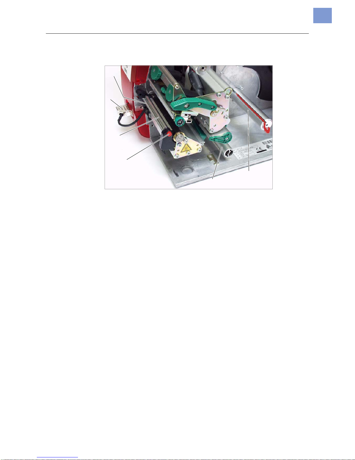
[10] Additional operating parts of the „AP5.4 Dispenser“.
A Dispensing edge:
Peels the labels off the backing paper.
B Connector:
Connection of the dispensing edge sensor.
C Dispensing roller:
Holds the material web tight over the dispensing edge.
D Dispensing roller release button:
Press the red button to release the dispensing roller.
E Deflector:
Deflects the backing paper.
F Rewinder:
Wraps up the backing paper.
A
B
C
D
E
F
Page 10
05/09 Rev. 5.02-01 USER MANUAL Setup & Operation
AP 4.4 – AP5.4
10
AP5.4 Internal Rewinder
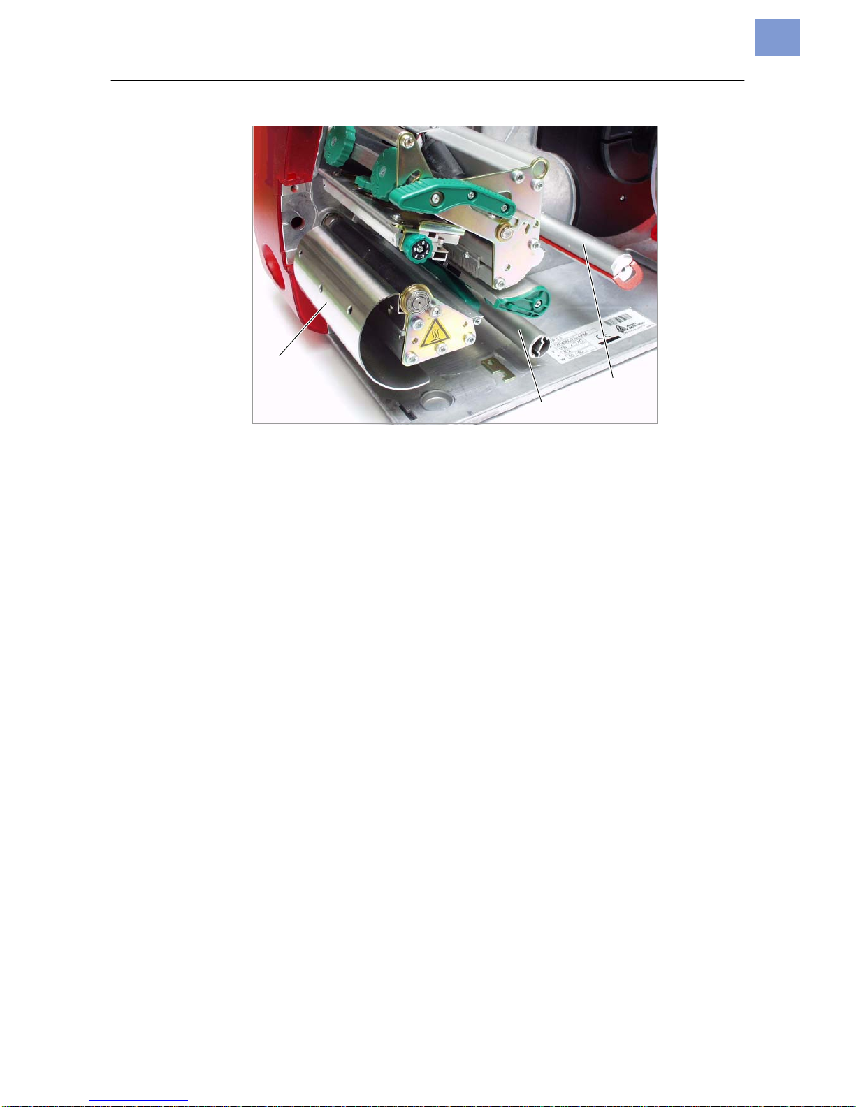
[11] Additional operating parts of the „AP5.4 Internal Rewinder“.
A Deflector:
Deflects the printed label web without dispensing any labels.
B Deflector:
Deflects the label web.
C Rewinder:
Wraps up the label web.
A
B
C
Page 11

05/09 Rev. 5.02-01 USER MANUAL Setup & Operation
AP 4.4 – AP5.4
11
Modes of Operation AP5.4 Dispenser / Internal Rewinder
With the AP5.4 featuring an internal rewinding module, a label can either be
dispensed (using the dispensing edge) or rewound into the printer housing
(using the deflector) after it is printed.
• If the printer’s Dispenser is used, the label is pulled over the dispensing
edge, and the backing paper is rewound.
• If its Rewinder is used, the printed label is redirected by a deflector and re-
wound together with its backing paper.
The electronics of the rewinder regulate the pull force exerted on the backing
paper so that the same force is exerted regardless of the roll diameter. The pull
force also depends on the material width and the printing speed. The pull force
is either regulated automatically using default parameters, or it can be set
manually.
¯ Manual setting is only required in special circumstances and should always
be carried out by a qualified authorised service technician.
After the printer is switched on, the rewinder is initialised and the label material
is stretched.
If a print job has already been received, the printer searches for the first punch
at reduced print speed. The label material is wound forward by the distance
between the punch sensor and the printhead (70 mm). This distance is used
by the rewinder’s control electronics to calculate the diameter of the backing
paper roll already wound up. To enable the control electronics to calculate diameters even when using continuous material, printing is also suspended for
the first 70 mm. Processing of the print job then commences at the print speed
set on the printer or by the print job.
Should operational issues occur, the rewinder is switched off automatically.
When the maximum diameter of the backing paper roll is reached, a corre-
sponding message is displayed and the rewinder is switched off automatically.
Dispenser Modes The following modes of operation are available for the dispenser:
• Dispenser Mode with Dispensing Edge Sensor:
Material is fed right up to the dispensing edge, that is the label to be dispensed sticks to the dispensing edge (set dispensing position). The printer
only feeds the next unprinted label backwards underneath the printhead
and begins printing, once the previous label has been taken off.
• Dispenser Mode with Foot Switch:
Depressing the foot switch triggers the printing and dispensing of one label. The next unprinted label is immediately positioned under the printhead.
See Activate/Deactivate Dispenser on page 20.
Page 12
05/09 Rev. 5.02-01 USER MANUAL Setup & Operation
AP 4.4 – AP5.4
12
Arrangement of the Connections
For information about using the network connection, please read topic section
Advanced Applications .
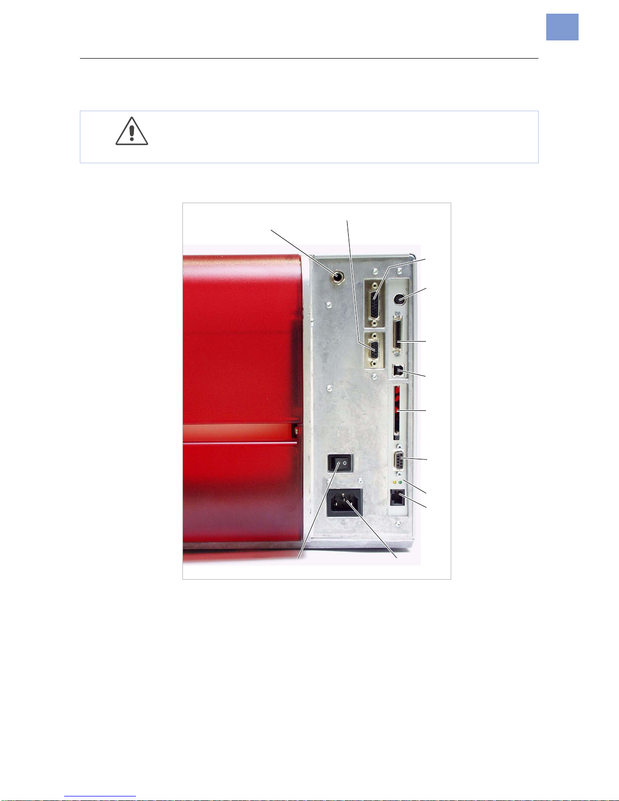
[12] Back view of the AP5.4 with mounted I/O board (accessory).
A Start/stop signal input:
(Optional) Connection for a treadle switch (signal starts the printer) or a
stacker (signal stops the printer).
B Serial Interface:
RS232 or RS422/485, on the optional available I/O board.
C Signal interface:
4 inputs / 3 outputs, belongs to the optional available I/O board.
CAUTION! - Additional equipment of poor quality can damage the printer
« Connect only devices that fulfill SELV circuit requirements to EN60950.
« Connect only original accessories.
A
B
C
D
E
F
G
H
I
J
KL
Page 13

05/09 Rev. 5.02-01 USER MANUAL Setup & Operation
AP 4.4 – AP5.4
13
D Keyboard connection:
In offline mode, the keyboard can be used for data input and print job
selection.
E Centronics connection:
For parallel transfer of print data.
F USB connection:
For serial transfer of print data.
G Card insert:
For CompactFlash cards, which can be used to save fonts, logos or
graphics.
H RS232 interface:
For serial transfer of print data.
I Status LED/Ethernet
J Network connection:
Connection for an “Ethernet 10/100 Base T” network.
K Power supply:
Connection to the power supply using the supply cable provided.
L Power switch:
Turns printer on/off.
Page 14
05/09 Rev. 5.02-01 USER MANUAL Setup & Operation
AP 4.4 – AP5.4
14
Warning Signs at the Printer
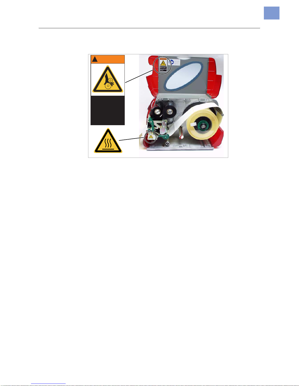
[13] Warning signs at the AP 4.4/5.4.
The warning sign pictured in [13] above warns of the risk of getting hands, fingers, loose clothing, jewellery, etc. drawn in between rotating parts of the printer (part no. A5346).
The warning sign pictured in [13] below warns of the risk of getting hands or
fingers burned at hot surfaces close to the printhead (part no. A5640).
« Immediately replace missing or unreadable warning signs!
WARNING
!
Pinch point.
Keep hands clear
of rollers.
A5346
Page 15
05/09 Rev. 5.02-01 USER MANUAL Setup & Operation
AP 4.4 – AP5.4
15
Control Panel (Display)
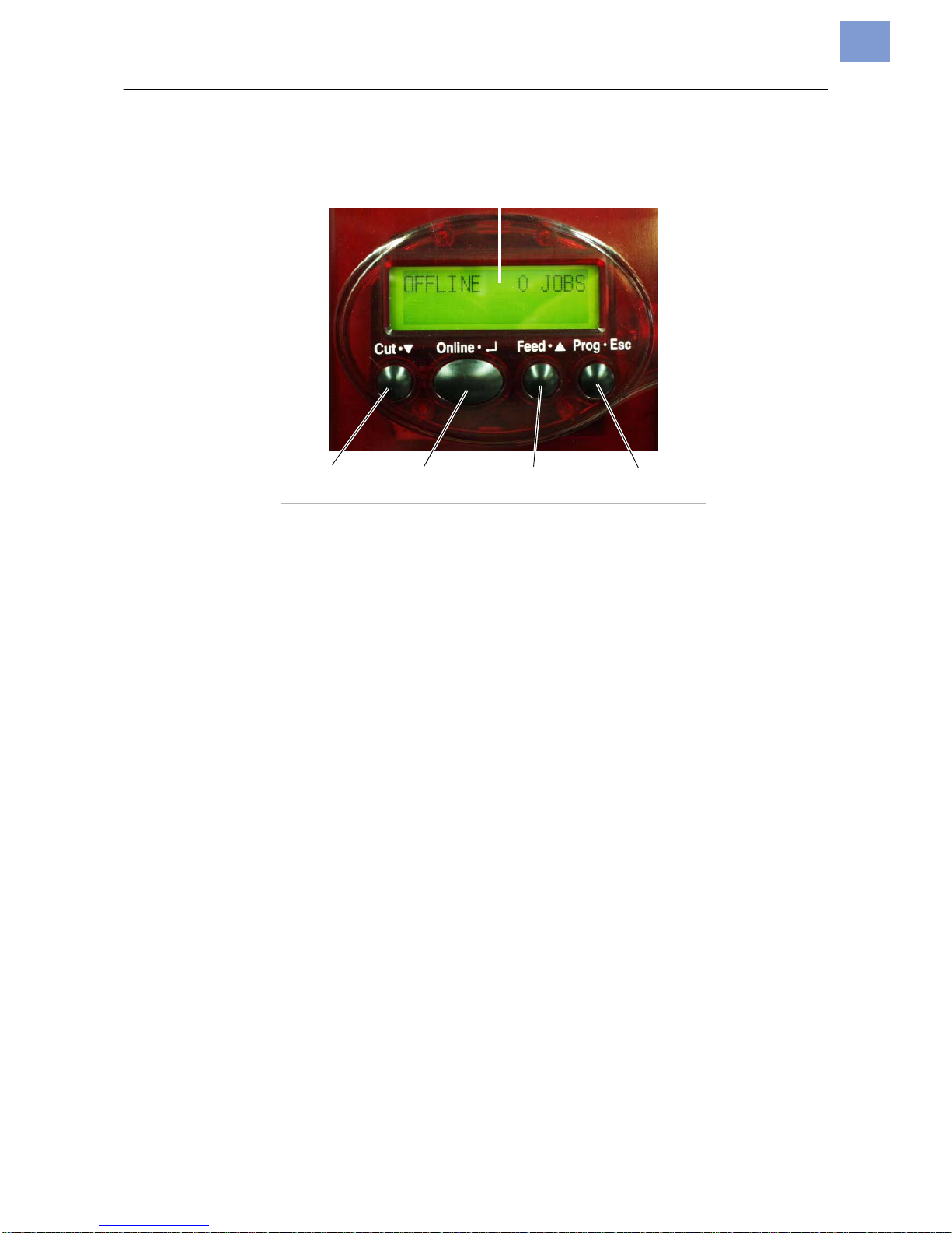
[14] Control panel for the AP5.4.
A Display
With 32 digits and two lines, the display shows the operating conditions
(modi) for parameters, values, status and errors. You can select the language you want to use for the display. The backlight ensures good legibility.
B Button Functions
General: The buttons offer a multitude of operating functions. A logical
menu structure is used for operation. The meaning of each button varies
according to the operating condition and the menu item. Additionally, special functions have been programmed for certain button combinations.
Despite this diverse range, it is possible to identify the following main functions:
C Online Button
– Switches between online and offline mode.
– Confirms inputs, menu items or displays.
– Selecting print jobs and inputting field values in standalone mode.
D Cut Button
– Triggers a cut. Requirements:
– Cutter fitted and activated
– Printer offline
– Additionally, directs to deeper levels within the menu structure and se-
lects menu items
– Reduces values
E Feed Button
– Feeds material when the device is offline
– Starts the printing process, once feed has been stopped (in online
mode)
A
BC D E
Page 16

05/09 Rev. 5.02-01 USER MANUAL Setup & Operation
AP 4.4 – AP5.4
16
– Additionally, directs to deeper levels within the menu structure and se-
lects menu items
– Enlarges values
F Prog Button
– Calls up the parameters menu when offline
– Goes back one step in the parameters menu, and/or quits the parame-
ters menu.
For more detailed descriptions of the button functions, please see
• Sections Operation in Offline Mode on page 21 and Operation in Online
Mode on page 22.
• Section „Info-Printouts and Parameters”.
Operating State
Offline Mode
No jobs are waiting to be processed.
Printer settings can be made when the device is offline. The offline mode is
normally active when the printer is switched on. Print jobs are received, but not
processed, via the selected interface.
¯ To adjust the printer so that it goes online directly after you have switched
it on, set SYSTEM PARAMETER > Turn-on mode to Online:
Online Mode In the online mode, print jobs are received and processed immediately.
• No jobs are waiting to be processed.
• Current data transfer to the printer is shown on the display: This is indicat-
ed on the right, underneath the number of loaded jobs.
Another point on half line height above the first shows the interpreter status:
– No point: No data to interpete.
– Solid point: The interpreter is busy (still data left in the spooler).
– Flashing point: The interpreter is waiting for data required to complete
a command (no data in the spooler).
• During printing, the display also shows the number of print jobs read (13)
and the remaining number of labels (25) to be printed in the current job.
• If a print job recognizes an infinite number of labels to be printed, then the
remaining number for this job is also shown as infinite.
OFFLINE 0 JOBS
ONLINE 0 JOBS
ONLINE 0: JOBS
ONLINE 13 JOBS
Restcount: 25
ONLINE 13 JOBS
Restcount: endless
Page 17

05/09 Rev. 5.02-01 USER MANUAL Setup & Operation
AP 4.4 – AP5.4
17
¯ To stop printing, press the online button.
Message Mode The printer uses the message mode to signal an error or a particular opera ting
status. Message mode indicates that the printer is waiting to quit or for a fault
to be corrected. When exiting, the printer switches from message mode to offline mode (depending on the error and the progress of the previous process).
Messages are made up of the status number and a brief descriptive text:
The messages 5001 (see above) e.g. occurs, if the printer is set for using labelling material with perforation, but continuous form material without perforation is inserted. In this example, the printer will continue to feed the material
for a few seconds before it finally sends an error message.
More information on message reports and a detailed list of all messages can
be found in topic section Status Messages .
Standalone Mode (For AP5.4 only)
In standalone mode, the print jobs are not transmitted via a data cable, but are
stored on a CF-Card. From there, they can be selected using the printer display or an keyboard connected to the printer.
For detailed information about using the standalone mode, refer to topic
section Advanced Applications .
Status 5001
No punch detected
Page 18

05/09 Rev. 5.02-01 USER MANUAL Setup & Operation
AP 4.4 – AP5.4
18
Basic Operating Procedures
Connecting the Printer
1. Ensure that the printer power switch is set to “0” (Off).
2. Connect the printer to the power supply using the cable provided.
3. Using the data cable supplied, connect the Centronics interface on the
printer to the host computer.
4. Turn on the printer using the power switch (switch to position “1”).
– The boot loader has started.
– Valid firmware program recognized, program will be started.
– Printer type (here: AP5.4)
Version number of the printer firmware.
– Internal RAM (here: 8 MB)
Optional RAM on the CompactFlash card (here: 32 MB) – only displayed when a CompactFlash card is in use.
– Offline mode
WARNING!
Printer is driven by mains voltage! Touching of live parts can cause life-
threatening body currents and burns!
« Make sure, that the machine is switched off, before connecting the po-
wer cable.
« Only connect the printer to a power socket that provides the correct
voltage, which can be found on the rating plate.
« Only connect the printer to a grounded power socket fitted to authori-
zed standards.
« When laying the power supply cable, ensure that:
a) no one can trip over it.
b) no one can step on it.
c) the power supply cable can be pulled out of the power outlet, if
necessary.
System start...
System start...
Start user prog
Avery AP5.4
V 1.02
Memory: 8MB
Flashcard: 32MB
OFFLINE 0 JOBS
Page 19

05/09 Rev. 5.02-01 USER MANUAL Setup & Operation
AP 4.4 – AP5.4
19
5. By pressing the online button you can switch to the online mode:
¯ When the parameter SYSTEM PARAMETER > Turn-on mode is set to Online, the
printer switches directly to online mode when it is turned on!
Setting the Interface
According to the factory settings, the AP4.4/5.4 is set for data transfer via the
Centronics interface. Print data can also alternately be transferred via the
RS232, USB or Ethernet interface (AP5.4 only).
« Settings for the interfaces are made using the following parameter:
Set INTERF. PARAM. > EASYPLUGINTERPR to Interface
To find out how to set parameters, see topic section “Info-Printouts and
Parameters”.
For part numbers of of power or data cables refer to topic section
„Accessories“.
For detailed information about using the Ethernet interface, refer to topic
section Advanced Applications .
Activate/Deactivate Internal Rewinder
¯ Only applies to the model AP5.4 with internal rewinder and deflector!
Deactivate « Set SYSTEM PARAMETER > Periph. Device to None
¯ If you do not insert printing material before activating the rewind function,
an error message will be displayed.
For details on how to insert printing material, see topic Setup , section ”In-
serting Label Stock”.
Activate 1. Call SYSTEM PARAMETER > Periph. Device to Intern Rewinder
¯ Not to be confused with Rewinder - this parameter activates the exter-
nal winder (optional extra)!
Upon activation, the rotational direction of the rewinder is set.
Facing outside is the default setting.
2. Press the Cut/Feed button to change the rotation direction.
3. Press Enter to confirm your setting.
The printer is restarted. The main menu now contains the additional menu
REWINDER PARA, which holds the parameter Rewind direction. This can be
used to change the rotational direction again.
During initialisation, the printer attempts to stretch the label material.
ONLINE 0 JOBS
Rewinder direct.
Facing outside
Page 20

05/09 Rev. 5.02-01 USER MANUAL Setup & Operation
AP 4.4 – AP5.4
20
Possible Errors Shortly after activating the internal rewinder, the following error message may
be displayed:
Possible causes:
• No printing material has been inserted, or the material’s end was not fixed
to the rewinder. Attach the end to the rewinder and press the Online button.
• The printing material is not stretched taut. Press the Online button.
The printer is now ready for the next print job. As soon as the print job is received, the rewinder’s control electronics analyse the material width and print
speed as specified by the print job and calculate basic initialisation settings for
the rewinding process. These settings cover most areas of application.
In some challenging applications, a reduced impression accuracy may occur.
In cases like these, the basic initialisation settings can be changed. This may
be necessary in the case of:
• Very small labels
• Very rough backing paper
• Backing paper much heavier than label
• Labels stuck to backing paper
• Backing paper perforated along label contour
¯ Basic initialisation settings may only be changed by a qualified authorised
service technician!
Activate/Deactivate Dispenser
¯ Only applies to the model AP5.4 with internal rewinder and dispensing
edge!
Deactivate « Set SYSTEM PARAMETER > Periph. Device to None
Activate « Call SYSTEM PARAMETER > Periph. Device to Dispenser
The printer is restarted. The main menu now contains the additional menu
DISPENSER PARA , which holds the parameters required for dispenser opera-
tion:
For more details on the listed parameters, see topic Info- Printouts and Para-
meters , section ”Operating the Parameter Menu”.
Status 5004
Rewinder mat. tear
Parameter Possible Settings
Dispenser Mode Real 1:1 mode (default), batch mode, normal 1:1 mode
Dispensing Position Set in millimeters (default: 0.0mm)
Display Mode Job rest quant. (default), Dispense counter
Dispense counter Preset Amount (default: 0)
Application Mode Safe Mode (default), Immediate Mode
Start Mode Edge (default), Level low active
Start Source Foot switch (default), Light barrier
[Tab. 1] Parameters in the menu DISPENSER PARA.
Page 21

05/09 Rev. 5.02-01 USER MANUAL Setup & Operation
AP 4.4 – AP5.4
21
Configure Dispenser
Application A The label is dispensed so that a small portion still sticks to the backing paper
above the dispensing edge. After the dispensed label has been removed by
hand, the next label is immediately printed and dispensed.
« Set DISPENSER PARA > Dispenseposition to –6.0mm (set to –8.0 mm if the ma-
terial is very adhesive).
« Set DISPENSER PARA > Start Source to Light barrier .
Application B The printing and dispensing of the label is triggered by a signal from the foot
switch connected.
« Set SYSTEM PARAMETER > External Signal to Stacker full.
« Set DISPENSER PARA > Dispenseposition to –6.0mm (set to –8.0 mm if the ma-
terial is very adhesive).
« Set DISPENSER PARA > Start Source to Foot switch .
Label length
< 40mm
¯ If very short lables are supposed to be printed (PRINT PARAMETERS > Material
length is set to a value < 40mm), the printer performs automatically a material
initialization, which improves the impression accuracy of the printout.
More details can be found in the description of parameter DISPENSER PARA >
Calibration mode in topic section „Info-Printouts and Parameters“.
Operation in Offline Mode
• Switching from offline mode to online mode:
• Switch to online mode when the print job is stopped:
• Slow material and ribbon feed:
• Material travels backwards under the printhead:
• Reset:
• Access the parameter menu:
OFFLINE x JOBS
ONLINE x JOBS
OFFLINE x JOBS
Stopped xx
ONLINE x JOBS
Stopped xx
OFFLINE x JOBS
OFFLINE x JOBS
feeding…
OFFLINE x JOBS
OFFLINE x JOBS
feeding…
OFFLINE x JOBS
OFFLINE x JOBS
OFFLINE x JOBS
PRINT INFO
Online
Online
Feed
Online
Cut Online
Cut Online
Feed
Prog
Page 22

05/09 Rev. 5.02-01 USER MANUAL Setup & Operation
AP 4.4 – AP5.4
22
• Feed material until the next punch is reached or as long as the button is
held down:
• Setting the label length automatically:
After pressing the two buttons, the printer feeds the label material, until two
punches have passed the label sensor. The measured label length then
will be displayed and saved into parameter PRINT PARAMETERS >
Material length. Furthermore, parameter PRINT PARAMETERS > Material type will
be set to „punched“.
Display of the measured label length:
¯ The label length measured by this function regards the label without the
following punch, what means from label end to label end. If label stock with
very large punches is used, this measurement will not work properly. In this
case, it is adviseable to measure and set the label length manually (label
length + punch length).
Operation in Online Mode
• Switching to offline mode:
• Setting the print contrast: Press the Feed button to increase and the Cut
button to decrease the print contrast.
• Interrupting the print job: The device will finish printing the current label.
• Switching to offline mode while the print job is stopped:
• Continuing the print job:
OFFLINE x JOBS
OFFLINE x JOBS
feeding…
OFFLINE x JOBS
OFFLINE x JOBS
Manual Calibrate
OFFLINE x JOBS
198.5 mm
ONLINE x JOBS
OFFLINE x JOBS
ONLINE x JOBS
Print contrast
xxx%
ONLINE X JOBS
Restcount XXX
ONLINE X JOBS
Stopped XXX
a
a) The message “Stopped xxx” alternates with “Press Feed”.
ONLINE X JOBS
Stopped XXX
OFFLINE x JOBS
ONLINE X JOBS
Stopped XXX
ONLINE X JOBS
Restcount XXX
Feed
Feed
Prog
Online
Prog
Prog
Online
Feed
Page 23

05/09 Rev. 5.02-01 USER MANUAL Setup & Operation
AP 4.4 – AP5.4
23
• Standalone operation: Selecting a print job stored on a CF card (e.g., Test-
dat.FOR):
Creating a Print job
Essentially, there are two ways of creating a print job: Either by using the
AP4.4/5.4 printer driver for Windows or by creating a text file with print commands.
Windows Printer Driver AP 4.4/5.4 printer drivers are available for different versions of Windows. You
can print from nearly every Windows application using the printer drivers.
However, functionality is strongly dependent on the choice of software. Special label layout programs are best suited, e.g. Jetmark 2000 or WinLabel.
You can download printer drivers from the Avery Dennison internet site
How to use the printer driver is explained by the driver’s help function. The help
function on your Windows operating system will tell you how to install a driver.
File with Print
Commands
You can write a sequence of commands in a text file and send it to the printer.
To do this, you can use any text editor and the MS-DOS copy command. Easy
Plug provides a special command language to formulate print jobs. However,
writing a print job in text file format does require some programming knowledge. Furthermore, you will not be able to preview the resulting printout on the
screen. Instead, you have to run a test print to see a copy of the finished result.
You can find a practice example of a print job together with instructions in the
Easy Plug Manual in the section “Program Example” under “General, Definitions Commands Overview”.
Transferring a Print Job
The printer can only complete a print job once this job has been transferred
into the printer’s RAM. This can be accomplished in two ways: using direct
transfer from your PC via a data cable or by saving to a CompactFlash (CF)
card.
Data Cable The print job can be transferred via parallel or serial communication. To do
this, connect the PC and the printer via the serial or parallel interface. Send
the print job file – from the DOS window – to the interface (e.g. “copy testjob.txt
lpt1” to send the print job to the parallel interface).
To send the print job from a text program, you need to ensure that the driver
for the relevant printer is installed.
Special label layout programs, such as Jetmark, make this much easier.
These programs also require a driver to be installed.
Card You require the following to load a print job from a CF card:
• a CF card, onto which you can copy the print job,
• a PC with a card reader
ONLINE x JOBS
Choose a file
Testdat.FOR
ProgOnline
Page 24
05/09 Rev. 5.02-01 USER MANUAL Setup & Operation
AP 4.4 – AP5.4
24
Rename the print job file on the CF card autostrt.for so that the printer can recognize it. Once this is finished, the printer will complete the print job as soon
as it is set online.
Using CF Cards (AP5.4)
(AP5.4 only)
CF = CompactFlash
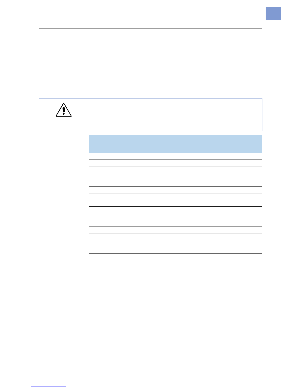
CAUTION! - Observe the following to avoid malfunctioning:
« Only use CF cards approved by the manufacturer
« Always wait at least 5seconds after switching off the printer before remo-
ving or inserting the CF card
Manufacturer Card type
Nominal
capacity
in MB
Usable
capacity
a
in MB
Hama USB-CF-Card 64MB 64 63
USB-CF-Card 128MB 128 126
Intenso CF-32MB 32 32
Kingmax KCF032MHT 32 32
KCF096MHT 96 94
Pretec 16MB 16 16
32MB 32 32
64MB 64 62
128MB 128 123
SanDisk 16MB 16 16
128MB 128 123
Silicon Tech SLCF032A 32 31
Toshiba Xtra speed professional 32MB 32 32
Xtra speed professional 64MB 64 62
Xtra speed professional 128MB 128 123
[Tab. 2] For the use with AP5.4 approved CF cards
a) Capacity detected by the printer electronic.
Page 25
05/09 Rev. 5.02-01 USER MANUAL Setup & Operation
AP 4.4 – AP5.4
25
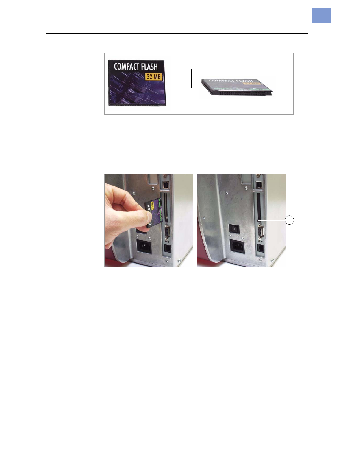
[15] Example of a 32MB CF-card.
Inserting a CF card 1. Switch off the printer. Wait for 5 seconds.
2. Insert the CompactFlash card completely into the card insert. The wide
guide notch should face upwards [16].
¯ Insert the CF card into the designated slot until the release button [16A]
is pushed outwards. The insert card will sit flush with the back casing.
[16] Inserting a CF card. If the CF card has been inserted correctly, then it will sit flush with the printer’s
back casing (right).
¯ For more detailed information on how to use CF cards, please refer to the
Plugin Card Manual, topic section Application , section “CompactFlash
Card”.
Wide guide notchSlim guide notch
A
Page 26

05/09 Rev. 5.02-01 USER MANUAL Setup & Operation
AP 4.4 – AP5.4
26
Setting the Realtime Clock (AP5.4)
The AP5.4 realtime clock can be used to calculate and to print the expiration
date of any perishable goods.
Read here how to set the realtime clock:
1. Call parameter SYSTEM PARAMETERS > Realtime clock
dd=day, mm=month, yyyy=year, hh=hour, mm=minute
2. Type in date and time: pressing the cut button shifts the cursor, pressing
the feed button changes the setting and by pressing the online button, the
setting is acknowledged.
How to set parameters: read topic section Info-Printouts and Parameters .
Reading out real time with Easy-Plug (AP5.4)
(AP5.4 only)
Reading out real time is done by using one of the following Easy-Plug com-
mands:
• #YC realtime as text
• #YS realtime as bar code
• #VDD defining date and time variables
Detailed Information provides the Easy-Plug Manual .
Realtime clock
dd.mm.yyyy hh:mm
 Loading...