

Page 1

Proprietary Statement
This manual contains proprietary information of Avery Dennison. It is intended solely for the
information and use of parties operating and maintaining the equipment described herein. Such proprietary
information may not be used, reproduced, or disclosed to any other parties for any other purpose without the
expressed written permission of Avery Dennison.
Product Improvements
Continuous improvement of products is a policy of Avery Dennison. All specifications and signs are
subject to change without notice.
FCC Compliance Statement
NOTE: This equipment has been tested and found to comply with the limits for a Class B digital device, pursuant
to Part 15 of the FCC Rules. These limits are designed to provide reasonable protection against harmful
interference in a residential installation. This equipment generates, uses, and can radiate radio frequency energy
and, if not installed and used in accordance with the instructions, may cau se harmful interference to radio
communications. However, there is no guarantee that the interference will not occur in a particular installation. If
this equipment does cause harmful interference to radio or television reception, which can be determined by
turning the equipment off and on, the user is encouraged to try to correct the interference by one or more of the
following measures: ■ Reorient or relocate the receiving antenna. ■ Increase the separation between the
equipment and the receiver. ■Connect the equipment into an outlet on a circuit different than that to which the
receiver is connected..
■Consult the dealer or an experience Radio/TV technician for help.
NOTE: This unit was tested with shielded cables on the peripheral devices. Shi elded cables must be used with
the unit to insure compliance. The user is cautioned that any changes or modifications not expressly approved by
Avery Dennison could void the user’s authority to operate the equipment.
Liability Disclaimer
Avery Denniosn takes steps to assure that its published engineering specifications and manuals are
correct; however, errors do occur. Avery Dennison reserves the right to correct any such errors and
disclaims liability resulting therefrom.
No Liability for Consequential Damage
In no event shall Avery Dennison or anyone else involved in the creation, production,
or delivery of the accompanying product (including hardware and software) be liable for any
damages whatsoever (including, without limitation, da mages for loss of business profits,
business interruption, loss of business information, or oth er pecuniary loss) arising out of the
use of or the results of use of or inability to use such product, even if Avery Dennison
has been advised of the possibility of such damages
A Letter to Our Customers
Dear Customers,
Congratulation on selecting an Avery Dennison AP 2.4 printer! We believe
soon you will find that you have made a cleverest choice!
This booklet is a small gift from us. It is intended for helping you to
know your printer better, then further to optimize it. Basically, this
booklet contains two parts: operation guidance and related valuable
information.
In the part of the operation guidance, we will furnish you with a lot of
complementary illustrations, so you may pick up those operation guides
more quickly.
In the latter chapters of Trouble Shooting, Maintenance as well as
Reference Technical information, which we think, you may need them
just in case. Therefore, for your quick reference, we try to table them as
much as possible.
Enjoy your reading and have a good time with your printer!
Best wishes,
Avery Dennison Printer Systems
Page 2

Page
Checking Your Box....................................................................1
Power Supply............................................................................. 3
Parts and Features..........................................................…….....5
Loading the Ribbon............................................………............9
Loading the Media......................................................……......14
Operator Controls..........................................................…........25
Performing Calibration .............................................................27
Printing Configuration Report...................................................27
Resetting the Printer........................................................…......28
Hooking up the Printer and the Computer..........................…...29
Communicate with the Printer..........................................….....32
Troubleshooting................................................................….....44
Caring for Your Printer............................................................. 48
Reference Technical Information.......................................... ....51
Appendix I-Installing Despenser Kit..................................… ...60
Appendix II -Installing Cutter................................................. ..66
Page 3

Checking Your Box
Receiving the box of your printer, you are advised to
check first for the possible shipping damage. There are two ways you can
do it:
1. Inspect the outer appearances of both the box and the printer for possible
damage.
2. Raise the top cover of the printer to see if the media compartments are in
order.
If damages did occur, immediately file the claim to the shipping company
for settlement.
Having performed the primary inspections, next step,
please check whether you have received the following accessories together
with the printer. If there is any item missing, contact your local dealer to get
it.
Printer
Sample Media
Ribbon
’
Note :
No sample media and ribbon are packed with AP 2.4.
1
2
Page 4

Power Supply
1. The Power Adapter has a barrel connector on one end that
must be inserted into the power jack on the back of the printer.
2. Plug the other end of the cord into an appropriate AC electrical
outlet.
WARNING:
NEVER OPERATE THE PRINTER AND POWER SUPPLY IN
AN AREA WHERE THEY CAN GET WET.
3. When plugging the connector into power jack, please leave the
power switch at "O" position and don't touch the 36 pin parallel
connector.
Power Switch
Power Adapter
OS-204/214/314
OS-202
3
4
Page 5

Parts and Features (AP 2.4)
Power Switch
Media Hanger
6
Thermal Printhead
Platen Roller
Peel-Off Option
White Plastic Roller
Cutter
Cutter Option
Ribbon Supply Holder
5
Page 6

Parts and Features AP 2.4
Thermal Printhead
H Cover
Ready indicator
Feed Button
Release Levers
Platen Roller
Media Hanger
8
Peel-Off Option Cutter Option
White Plastic Roller Cutter
7
Page 7

Loading the Ribbon
Note:
This section is not applicable to the direct thermal printing.
1. Lift the top cover to expose the media compartment.
2. Unlatch the print head module by pushing the two white release
levers on the sides toward the rear.
3. Turn over the print head module to expose the ribbon supply
holder.
10
Print Head Module
Release Lever
Ribbon Supply Holder
9
Page 8

4. Unwrap the ribbon roll pack and separate the ribbon roll and
the bare core.
7. Turn back the print head module and then insert the bare core
into the pick-up holder.(first snap in the left side, then the right
side) 5. Attach the edge of the ribbon on the bare core and wind it a
little bit onto the core.
6. Insert the ribbon roll into the supply holder. (first snap in the left
side and then the right side)
Ribbon Supply Holder
Ribbon Roll
12
Ribbon Pick-up Holder
Bare Core
11
Page 9

Loading the Media
8. Turn the wheel of the print head module to ensure the ribbon is
tightly wound.
9. Press down the print head module firmly till you hear a snap.
OS Series printers can be operated in three different options:
standard, peel-off, or with a cutter.
- Standard mode allows you to collect each label freely.
- In peel-off mode, the backing material is being peeled away from
the label as it is printed. After the former label is removed, the
next one will be printed.
- In cutter mode, the printer automatically cuts the label after it is
printed.
Standard Mode
1. Lift the top cover to expose the media compartment.
Print Head Module
14
13
Page 10

2. Remove the media hanger. 4. Click the media hanger back to the media compartment.
3. Load the media roll onto the hanger from the left. 5. Move the media roll to the left end.
6. Move the shield to the left next to the media.
Media Compartment Media Hanger
Media Compartment
Media Roll
Media Roll
Shield
15
16
Page 11

7. Unlatch the print head module. 10. Turn back the print head module and then press it down firmly
till you hear a snap. 8. Hold the print head module upright with one hand to allow the
media pass under it. Lead the media through the media guides
with the other hand.
11. Close the top cover and turn on the printer or press the feed
button if the printer is already on.
9. Lead the media over the platen roller.
Print Head Module Media Guides
18
Print Head Module
Feed Button
17
Page 12
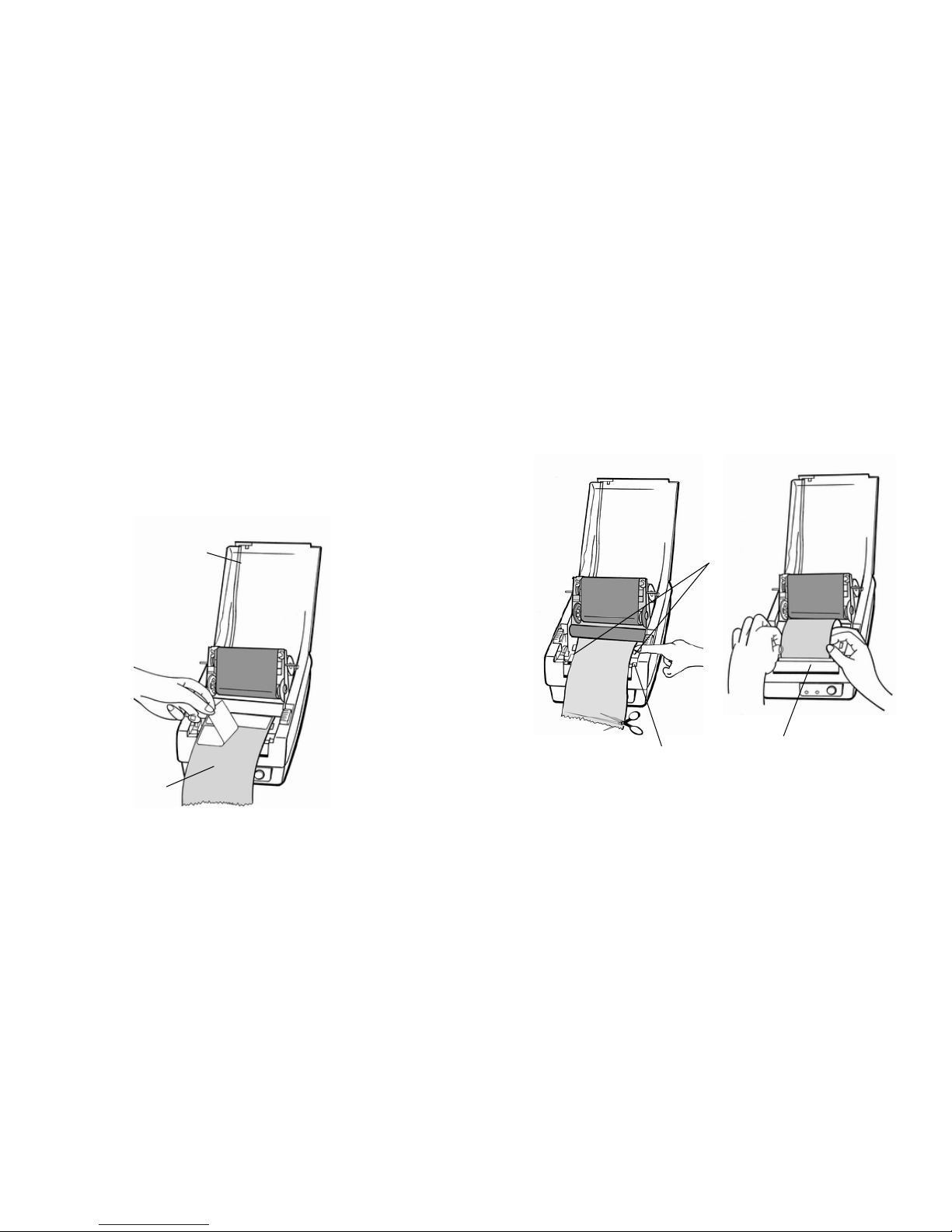
Peel Off Mode
10. Trim the edge of the label backing paper with scissor or knife.
11. Lead the backing paper over the dispenser bar, then thread it
back into the slot between the dispenser bar and H cover,
ensuring that it is inserted between white plastic roller and
platen roller.
(Installing the dispenser kit, please refer to the Appendix I)
Follow the common procedure of "Loading the Media"of Standard
Mode from step 1 to step 8.
9. Remove approximately 6" long labels from the label backing
paper.
Backing Paper
Peeler Sensor
20
H Cover
Media Guides
Dispenser Bar
19
Page 13
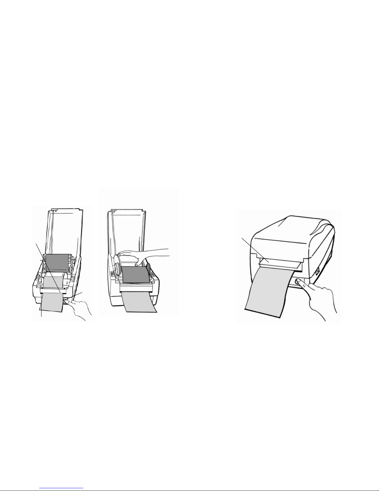
12. Press "FEED" button and the label backing paper will come
out from the slot under the H cover.
15. Close the top cover and turn on the printer or press the
"FEED"
button if the printer is already on.
13. On OS-202 Peel-Off mode, powered on status, in case of
improper installation, just keep pressing the "FEED"button to
back-feed the label stock to re-install it.
Note :
14. To remove any slack, just rewind the media onto the roll.
Press down the print head module firmly.
The "FEED" button will not drive the printer to peel. The
peeling work can be executed only when the software
setting is ready.
Label
H Cover
Slot
Feed Button
21
22
Page 14
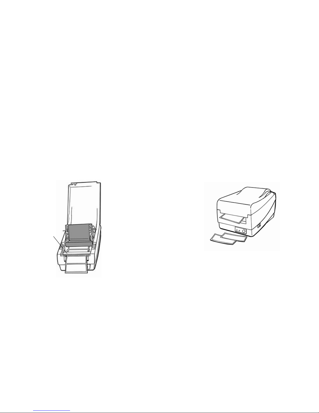
Cutter Mode
11. Close the top cover and turn on the printer or press the
"FEED" button if the printer is already on.
( Installing the cutter, please refer to Appendix II )
Follow the same procedure as "Loading the Media" from
Note:
step 1 to step 8.
The "FEED" button will not drive the printer to cut. The
cutting work can be executed only when the software
9. Thread the media over the platen roller, then route the media
through the slot of the cutter module.
setting is ready.
10. Press down the print head module firmly.
24
Cutter Module
23
Page 15
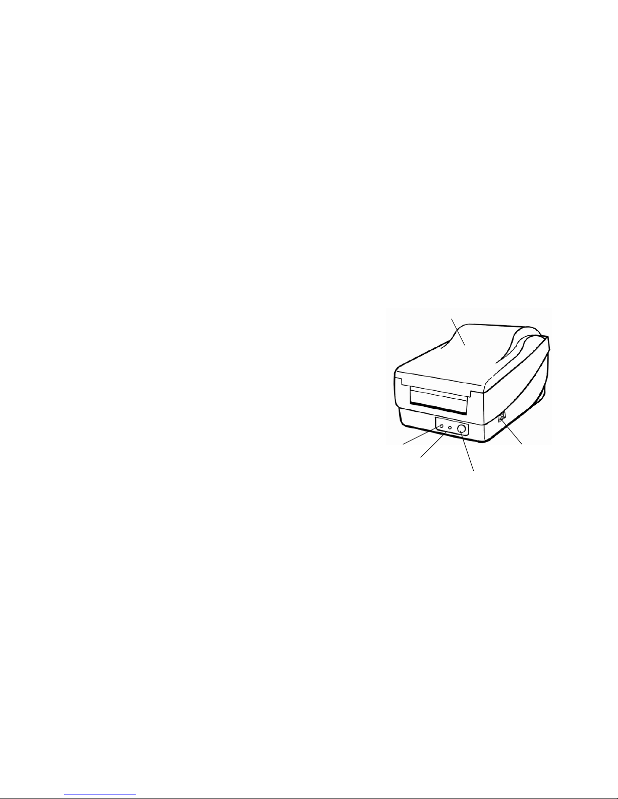
Operator Controls
Power Switch
Controls printer power
On-normal operation
Off-the power should be turned off before connect or disconnect
the communication cables and power cables
Feed Button
Advance the label media to first printing position
Press-to advance a label
Press-takes the printer out of a "pause" condition
Press-back feed the label to correct label installation, in case that
label is not properly installed. (for OS-202 Peel-Off mode only)
Keep pressing while turning on the power- to print out a
configuration profile
Ready Indicator
Show the printers status
Green-printer is ready to operate
Blinking-printer is paused
Power indicator
Shows the power and error status
Off-printer power off
Green-printer power on
Blinking-error occurs
26
Power Indicator
Ready Indicator
Power Switch
Top Cover
Feed Button
25
Page 16

Performing Calibration Resetting the Printer to Factory
Default Settings
1. Keep pressing the feed button while turning on the power, until
the printing motor becomes activated.
1. Turn on the printer and wait for 5 or more seconds.
2. The calibration has been performed while the printer
automatically feed label stock for certain length.
2. Press "Feed" button for about 10 seconds, then the "Ready"
indicator and "Power" indicator will go off in order.
3. While two indicators become lit again, release the feed button.
Note:
4. At this moment, the printer will feed the label stock 12 inches in
This step is very important and must always be carried
length, and come back to the factory default settings.
out whenever media is being changed. Failure to do so
will result in miss-detection of the label sensor.
Note :
All settings are stored in non-volatile E2PROM and
cannot be destroyed even turn off the printer.
Printing Configuration Report
1. Keep pressing the feed button while turning on the power, until
the printing motor becomes activated.
2. After feeding 12-inch blank media, the printing motor will
suspend for one second, then it will print out the configuration
profile. This profile states the firmware version, ROM checksum,
RS232, thermal transfer/direct thermal settings, hardware
configuration and font types.
3. At PPLB interpretation, the printer will enter character dump mode.
To exit from dump mode, just press the feed button again.
27
28
Page 17
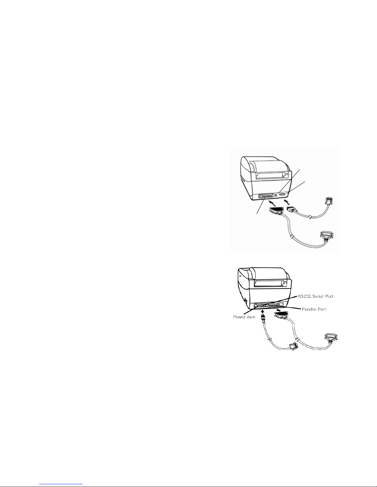
Hooking up the Printer and Computer
30
OS-204/214/314
Note :
Power Jack
The power supply barrel connector must be inserted into the
power jack on the back of the printer before connecting the
communication cables.
This printer comes with both a nine-pin Electronics Industries
Association (EIA) RS-232 serial data interface (for OS-202, it is
six pin) and a standard Centronics parallel interface. In either
case, you must supply the required interface cable for your
application.
Note :
This printer complies with FCC "Rules and Regulations" ,
Part 15, for Class B Equipment, using fully shielded six-foot
data cables. Use of longer cables or unshielded cables may
increase radiated emissions above the Class B limits.
Serial (RS-232) Interface Requirements
The required cable must have a nine-pin "D" type (for OS-202, six
pin) male connector on one end, which is plugged into the mating
serial port located on the back of the printer. The other end of this
signal interface cable connects to a serial port at the host
computer.
For technical and pinout information, please refer to the
Reference Technical Information-Interface Specification on page
55 of this booklet.
RS232 Serial Port
Parallel Port
OS-202
29
Page 18

Parallel Interface Requirements Communicate with the Printer
The required cable (IEEE 1284-compliant is recommended) must
have a standard 36-pin parallel connector on one end, which is
plugged into the parallel port located on the back of the printer.
The other end of the parallel interface cable connects to the
printer connector at the host computer. For pinout information,
refer to the Reference Technical Information- Interface
Specification on page 55. Serial and Parallel Cabling
Requirements.
The bundled printer driver can be applied to all the applications
under Windows 2000/98/95, and Windows NT. Through this
driver you may run any popular software applications e.g.
MS-Word and print out the contents by this label printer as long as
they are for Windows.
Before installation
1. Check the contents of the driver to ensure it is complete.
Data cables must be of fully shielded construction and fitted with
metal or metalized connector shells. Shielded cables and
connectors are required to prevent radiation and reception of
electrical noise.
2. Make a backup copy of this driver.
3. Read the README.TXT file for installation guide and change
notices.
To minimize electrical noise pickup in the cable:
■Keep data cables as short as possible (6 [1.83m]
recommended).
■Do not tightly bundle the data cables with power cords.
■Do not tie the data cables to power wire conduits.
Notes :
1. Using Centronics allows for a much higher speed
communication than the use of a serial.
2. It is not necessary to set the switch or send any command
to select the parallel or serial port . The printer can
automatically detect it.
3. The default settings can be read from the configuration
report.
31
32
Page 19

Installing Driver
Notes :
1. If you are just updating your driver, make sure to delete the
previous version first.
1. Click the "Start" button.
2. Select "Settings", then select "Printers" and double click the
"Add Printer" icon. Click "Next".
2. If you install a new bar code application software like
ArgoBar, LabelView or CodeSoft, the Label Dr. 200 (or
Label Dr. 300) driver should be activated and set as the
current printer driver:
3. Click the "Network" or "Local" button and click the "Next"
button.
4. Click "Have Disk", click the pull-down menu to select CD ROM
driver path.
ArgoBar
File → New→ Select Printer→ Label Dr. on LPT1:→ OK
5. Click "Browse" button.
6. Select the proper directory for installation:
LabelView
-WIN95
File→ Select Printer→ Label Dr. on LPT1:→ OK
-WIN98
-WIN2000
CodeSoft
File→ Printer→ Windows→ Label Dr. on LPT1:→ OK
-NT4.0
-
-
-
LabelMatrix
7. The driver name "Label Dr. 200" (or Label Dr.300) will appear
in the "List of Printers", click "Next".
File→ Printer Setup →Label Dr. on LPT1:→ OK
8. Select the communication port for the label printer. For parallel
port, select "LPT1 :", "LPT2 :" or "LPT3 :" , for serial port select
"COM1 :" or "COM2 :".
9. After the related files have been copied to your system, the
installation is complete.
10. If you need to print from the label printer, set "Label Dr. 200"(or
Label Dr.300) as the Default Printer.
33
34
Page 20
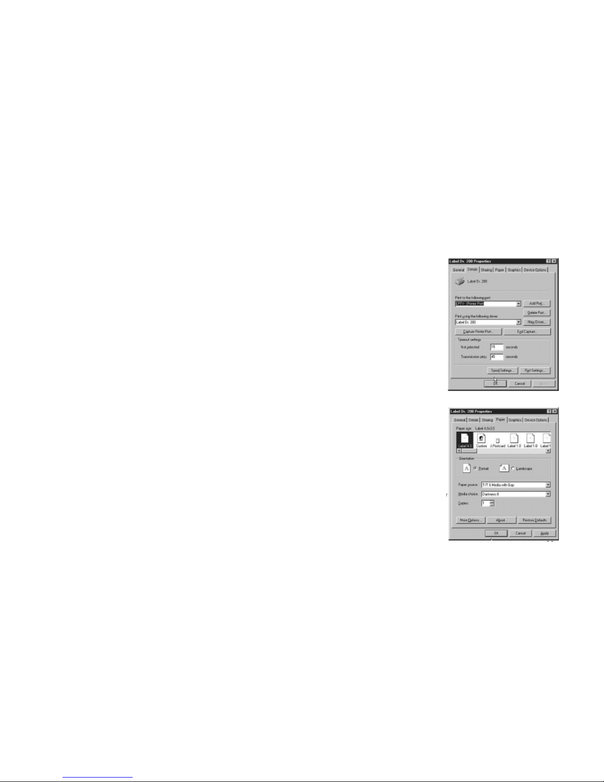
Set the Parameters For Win 98
▀ Ports
After installing the driver, you can follow the path below to set
parameters:
Properties menu
Start →Settings→ Printers→ Label Dr.→ Properties
→ click "Details"
→ select the IO port
The parameters include:
→ click "OK"
Ports Select the IO port to link with the printer. The port may be one of
parallel (LPT), serial (COM), network port or file.
Paper size Select the proper size on the menu. If there is no desired
size, select "Custom" to define the paper size.
Orientation Set portrait or landscape according to the print direction.
Paper source (Media type) T/T stands for thermal transfer (ribbon)
mode and D/T for direct thermal mode (without ribbon).
Media choice (Darkness) Set the heat value or darkness from this
field. The darkness value ranges from 0 to 15.
▀ Paper size
▀ Orientation
▀ Paper source
Copies This function designates the number of printed copies of each
page.
(Media type)
▀ Media choice
(Darkness)
More option (Accessory setting) To use the cutter and peeler
function you still need to enter More Options and select one of the items.
▀ Copies
Properties menu
→click "Paper"
Device options (Speed) Set the print speed. For the AP 2.4, the
speed ranges from 1 to 3 IPS.
→click each item to select
desired parameter
→click "OK".
36
35
Page 21
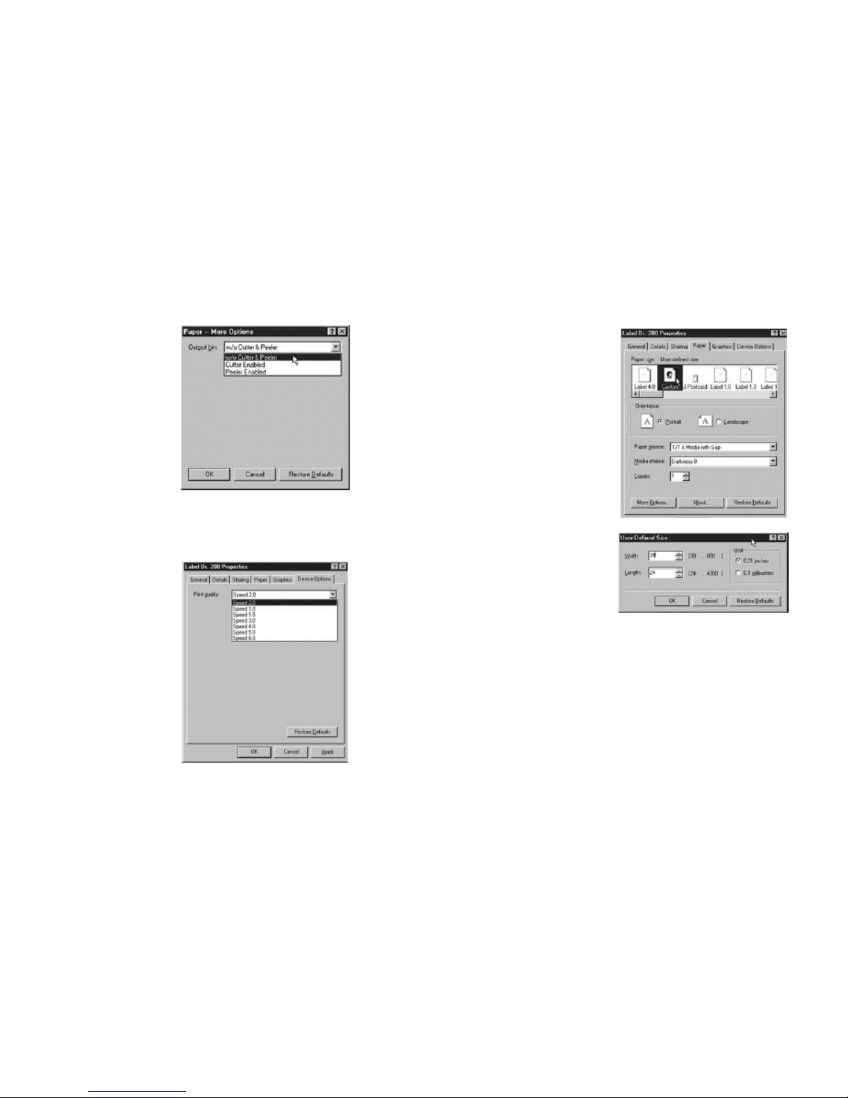
▀ Output bin
(Accessory setting)
Properties menu
→ click "Paper"
→ click "more option"
→ select Enable/without
→ cutter, peeler
→ click "OK"
▀Print quality
(Speed)
Properties menu
→ click "Device Options"
→ select parameters
→ click "OK"
38
▀ Create a new size
Properties menu
→ click "Paper"
→ select "Custom"
→ User-Define size
→ set up a new size
→ click "OK"
37
Page 22
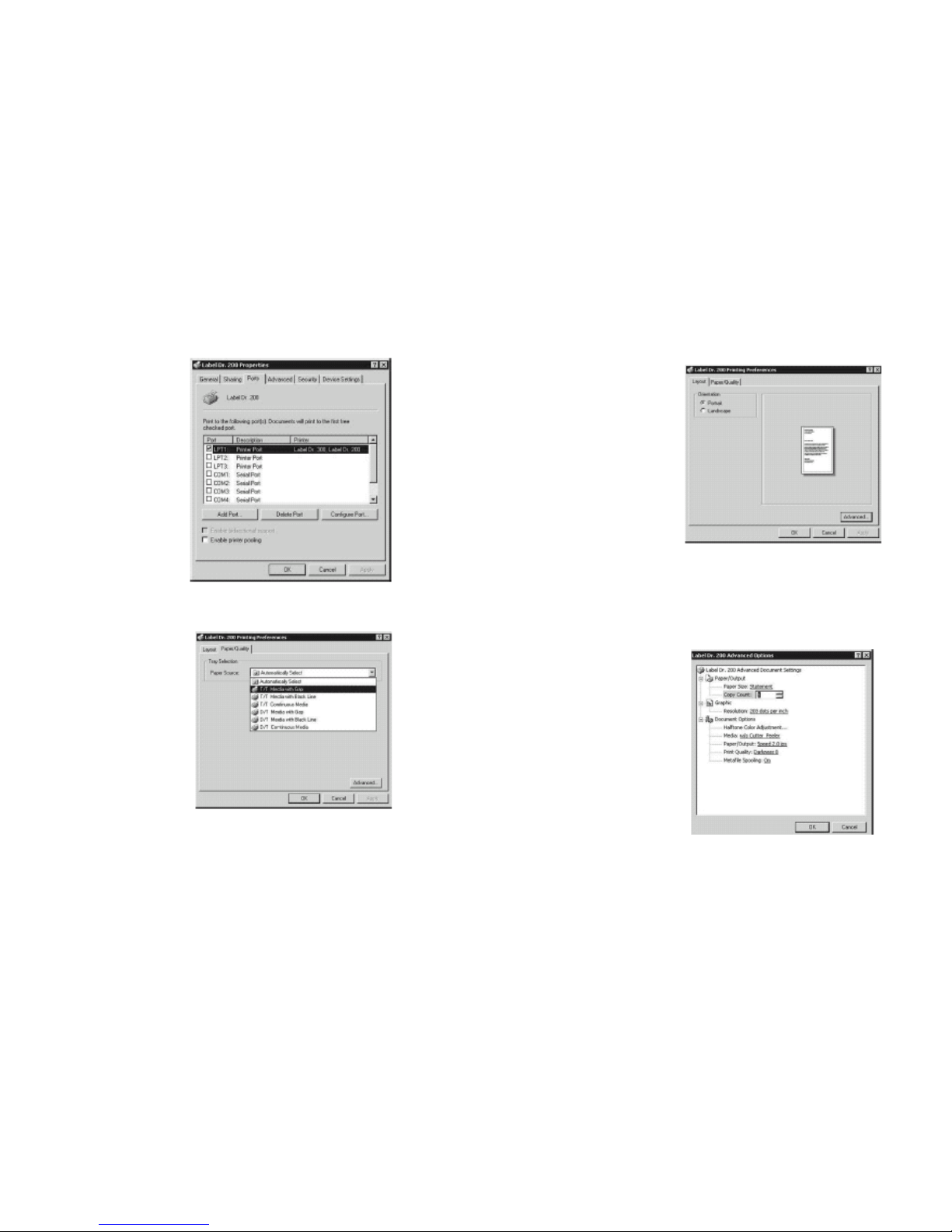
For Win 2000
▀ Ports
Properties menu
→ click "Ports"
→ select the IO port
→ click "OK"
▀ Paper source
(Media type)
Back to Printers menu
→right click to get
pop-up menu
→ select "Printing
Reference"
→ click "Paper Quality"
select media type
→ click "OK"
40
▀ Orientation
Printing Reference menu
→ click "Layout"
→ select "Portrait" or
"Landscape"
→ click "OK"
▀Paper size
▀Copies
▀Media choice
(Accessory setting)
▀Paper/Output
(Speed)
▀Print quality
(Darkness)
Printing Reference menu
→click "Layout"
→click "Advanced"button
→click each item to select
the parameters
→click "OK"
39
Page 23
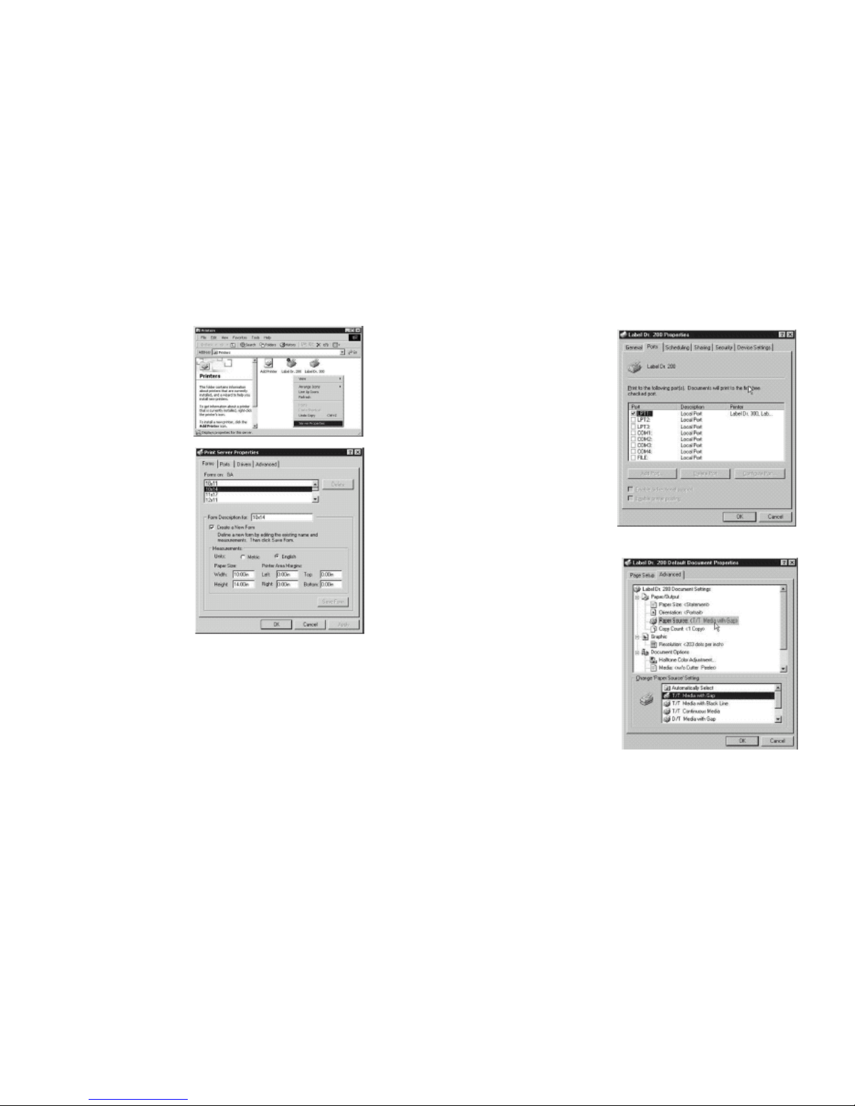
▀Create a new size For NT 4.0
Printer menu
→ right click to get pop- ▀Ports
up menu
Properties menu
→ click "Ports"
→ select "Server
→ select the IO port
Properties"
→ click " OK"
→ enter a form name for
the new form in "Form
description for"
→ reset the paper size in
the specific squares
of the "Measurements"
→ click "OK"
▀ Paper size
▀ Orientation
▀ Paper source
(Media type)
▀ Copies
▀ Media choice
(Accessory setting)
Printers menu
→ right click to get
pop-up menu
→ select "Document
Defaults"
→ click "Advanced" button
→ click each item to
select desired
parameter
41
42
Page 24
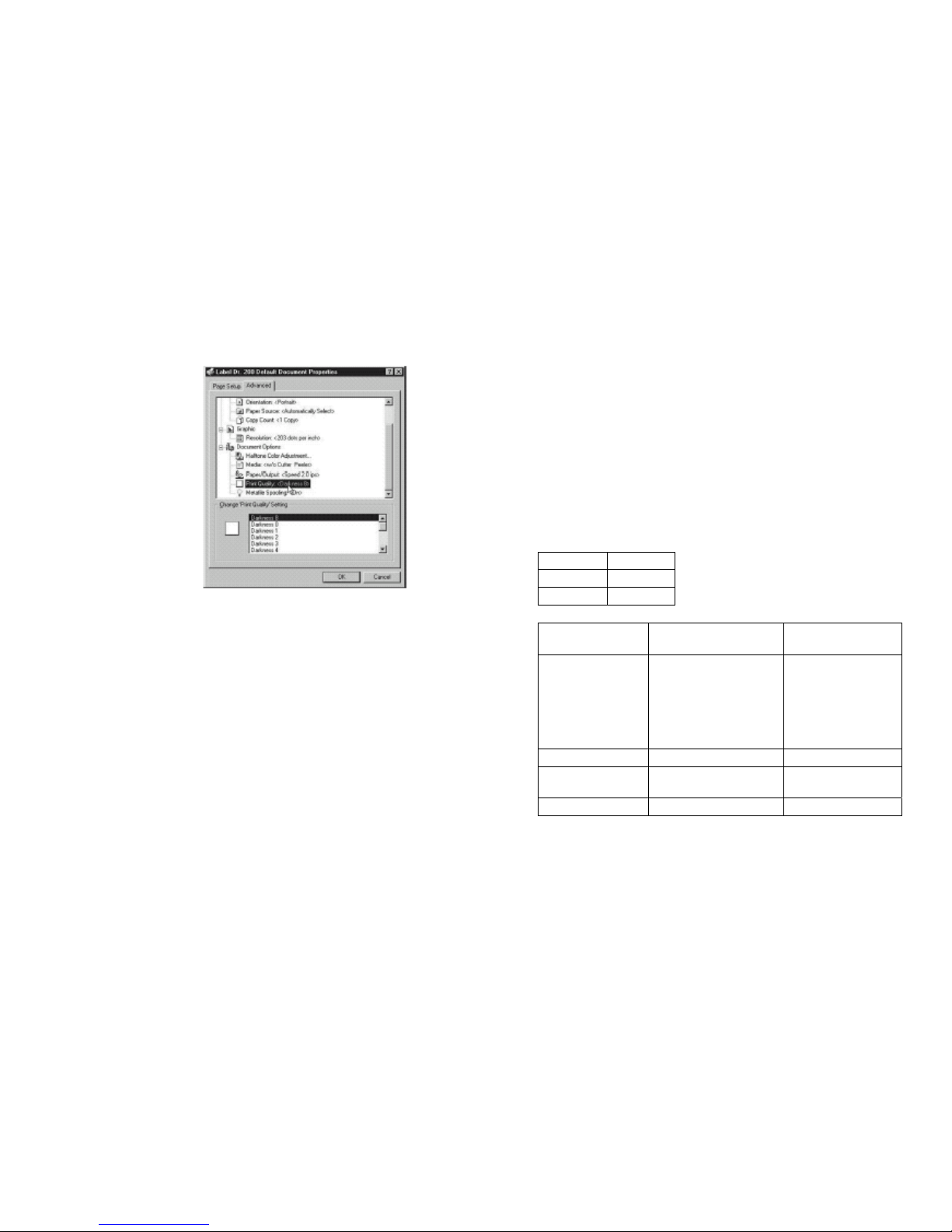
Troubleshooting
▀ Paper/Output
▀ (Speed)
Print quality
Normally, when the printer is in abnormal condition, the "POWER"
LED will keep blinking. The printing work and the communication
between the host and printer will stop.
(Darkness)
Default Document menu
To understand the problem, please check both
click "Advanced"
LEDs first:
click each item to
select desired
A. Power and Ready LEDs blink at the same tempo
parameter
click "OK"
Power LED Ready LED
ON ON
OFF OFF
▀ Create a new size
Please refer to the
procedure of create a
new size on Win 2000.
Possible
Problems
Solutions Remarks
Miss-detect the gap
. Check the label path
. Check the label sensor
If you are using
continuous label roll
and run under
Windows, you should
select the continuous
media.
Label stock out . Supply the label roll out
Label stock not
installed
. Install the label roll
Label jam . Recover the jam
43
44
Page 25
D. Miscellaneous
B. Power and Ready LEDs blink alternately
Power LED Ready LED
ON OFF
OFF ON
The host shows "Printer Time out"
1. Check if the communication cable(parallel or serial) is connected
securely to your parallel or serial port on the PC and to the
connector on the printer at the other end.
Possible Problems Solutions Remarks
Ribbon out Supply the ribbon roll
Ribbon jam Recover the jam
Ribbon sensor error Replace the ribbon sensor
Not applicable to
direct thermal type.
2. Check if the printer pow er is turned on.
If the power cord is connected, the power switch is at position "I" and
the power LED has still not illuminated, check the fuse inside the
power adapter case.
The data has been sent, but there is no output from the printer. Check
the active printer driver, if Label Dr. for your Windows system and the
label printer has been selected.
Note:
**For models OS-202/OS-204 such error will never
occur.
C. Only the Power LED blinks
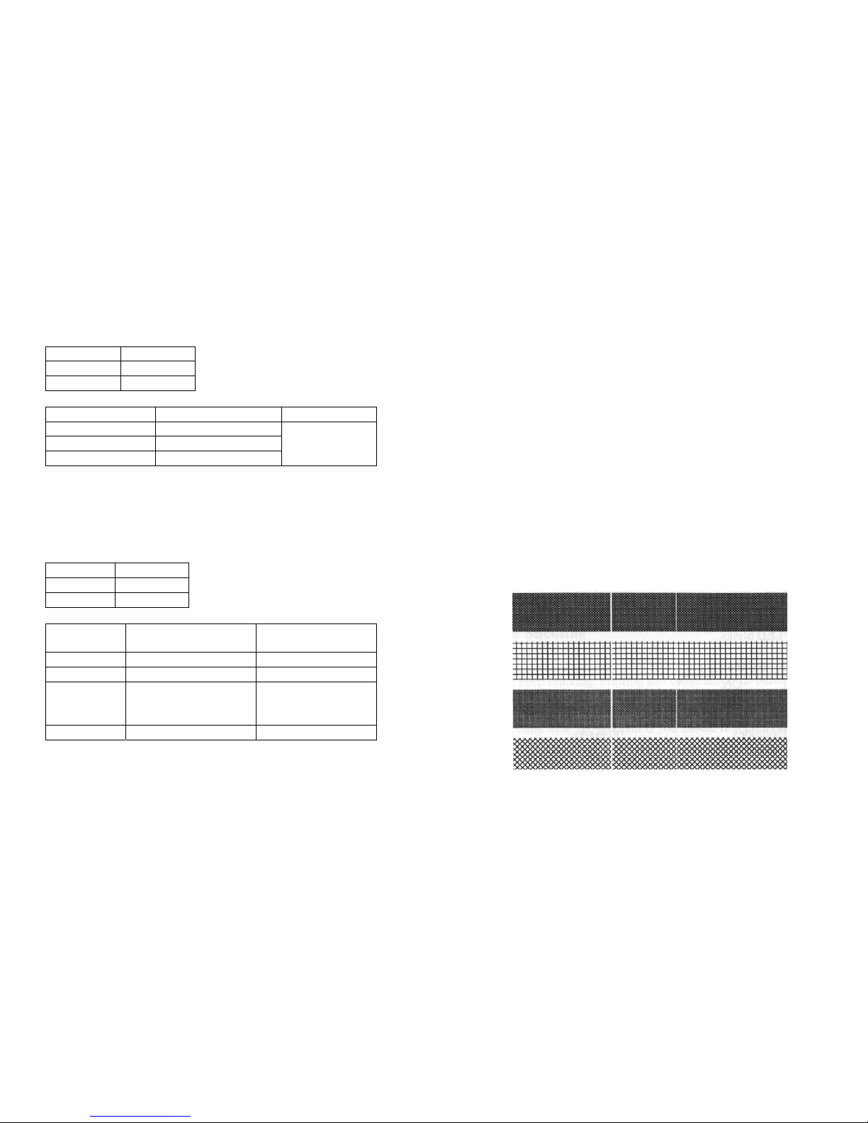
Vertical streaks in the printout usually indicate a dirty or faulty print
head.(Refer to the following example)
Power LED Ready LED
ON ON
OFF ON
46
Possible
Problems
Solutions Remarks
Serial IO error . Check the baud rate Not for Centronics
Memory full Add the extension RAM
Cutter failed, or
jam at cutter
. Check the cutter
. Recover the jam
It occurred, only when
cutter is installed, or the
setting of the cutter
Hardware error Call for service
Clean the print head first, if they still persist, replace the print head.
45
Page 26

Poor printout quality.
Caring for Your Printer
. The ribbon may not be qualified.
. The media may not be qualified.
Clean the following areas of the printer after 8 rolls of label stocks
have been used. In each case, use a cotton bud dampened with
alcohol. Do not soak the cotton bud excessively.
. Adjust the Darkness(heat temperature).
. Slow down the print speed.
. Refer to the next chapter and clean the related spare parts.
Note :
Recovery
Always switch off the power before cleaning.
To continue your print jobs after the abnormal conditions have been
corrected, simply press the panel button or restart the printer. Make sure
that the LED is not blinking and remember to resend your files
.
Cleaning
Thermal Print Head
Thermal paper stock and ribbon will release debris on the print
head and degrade printing quality. Clean the print head with
methanol or isopropyl alcohol with a cotton bud. Do not touch
the heater element with your fingers. Debris or dirt on the roller
should be cleaned with alcohol.
Paper Sensor
Debris or dirt on the paper sensor will cause a miss-read or
unstable detection of the label gap. Clean with a cotton bud
dampened with alcohol.
47
48
Page 27
Replacing Thermal Print Head
1. Switch off the power and wait for both LEDs to go off.
2. Unlatch the print head module.
3. Remove the ribbon.
4. Push the print head firmly into the casing and shift it to the left.
It will release from the module.
5. Disconnect the print head cable.
6. Dissemble the print head and the mounting bracket by
releasing screws.
7. Replace with new print head, then resemble the print head
module in reverse order. Be careful not to touch the print head
elements.
49
50
Page 28
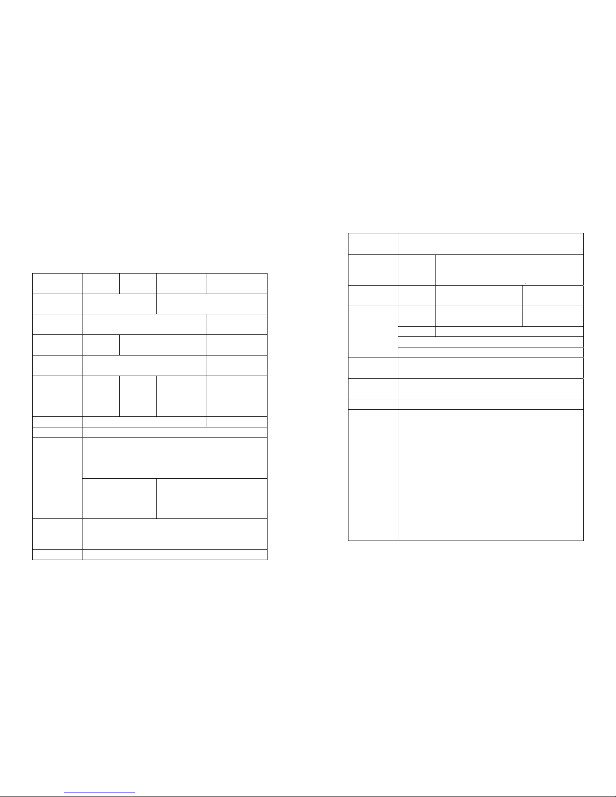
Reference Technical Information
1. General Specifications
Specification Model
OS-202DT
Model
OS-204DT
Model
AP 2.4
Model OS-314TT
Print method Direct thermal Direct thermal
and thermal transfer
Resolution 203 DPI (8 dots/mm) 300 DPI
(12 dots/mm)
Maximum print
width
2.20 in.
(56 mm)
4.13 in.
(105 mm)
4.25 in.
(108 mm)
Maximum print
length
45 in.
(1143mm)**
30 in. (762mm)**
Maximum print
speed
3.5 inches
(89 mm)
per
second
2 inches
(51 mm)
per
second
3 inches
(76 mm)
per second
2 inches
(51 mm)
per second
Onboard RAM 512 K bytes 2 M bytes
Rotation 0, 90, 180 and 270, 4 direction rotations
I. Direct thermal:
paper or vinyl, vinyl, visible light and infrared
scannable label, tag, stock, butt cut or die cut,
with various adhesives.
Media type
X II. All above media, plus thermal
transfer paper or vinyl labels
and tags, butt cut or die cut,
with various adhesives.
Maximum
label roll
diameter
4.3 in.(109mm) outside diameter, 1 in.(25 mm) inside
diameter
Label indexing Black stripe and gap
Ribbon types
Ribbon size
Wax, Wax/Resin and Resin
OD 1.45 in. (37 mm); ID 0.5 in. (12.7mm); Length11
Dimension W5.3 x
D9.0
x H6.4 in.
W7.3 x D10.9 x H6.0 in
Weight 1.2Kg
(2.6 lbs)
1.7 kg
(3.74 lbs)
1.9 kg
(4.1 lbs)
FCC
class A
FCC class B FCC class A
21VAC 19VAC
Or DC24V (min 2.5A), 50/60Hz
Electrical
CE, UL and CUL approved.
Operating
temperature
40°F ~ 100°F (4°C ~ 38°C)
Storage
temperature
40°F ~ 140°F (4°C ~ 60°C)
Humidity 15~85% RH
Optional
Accessories
● Serial (RS232) cable
● External media stacker
(for media roll with max. 8-inch OD)
● Dispenser Kit
● Cutter
● Flash memory
● Font board
● Extension RAM ++
(0.5M for models 204/214/314 only)
● RTC board
● USB-Interface
● Standalone KDU-ArgoKee
● Network print server-ArgoNet
52
51
Page 29
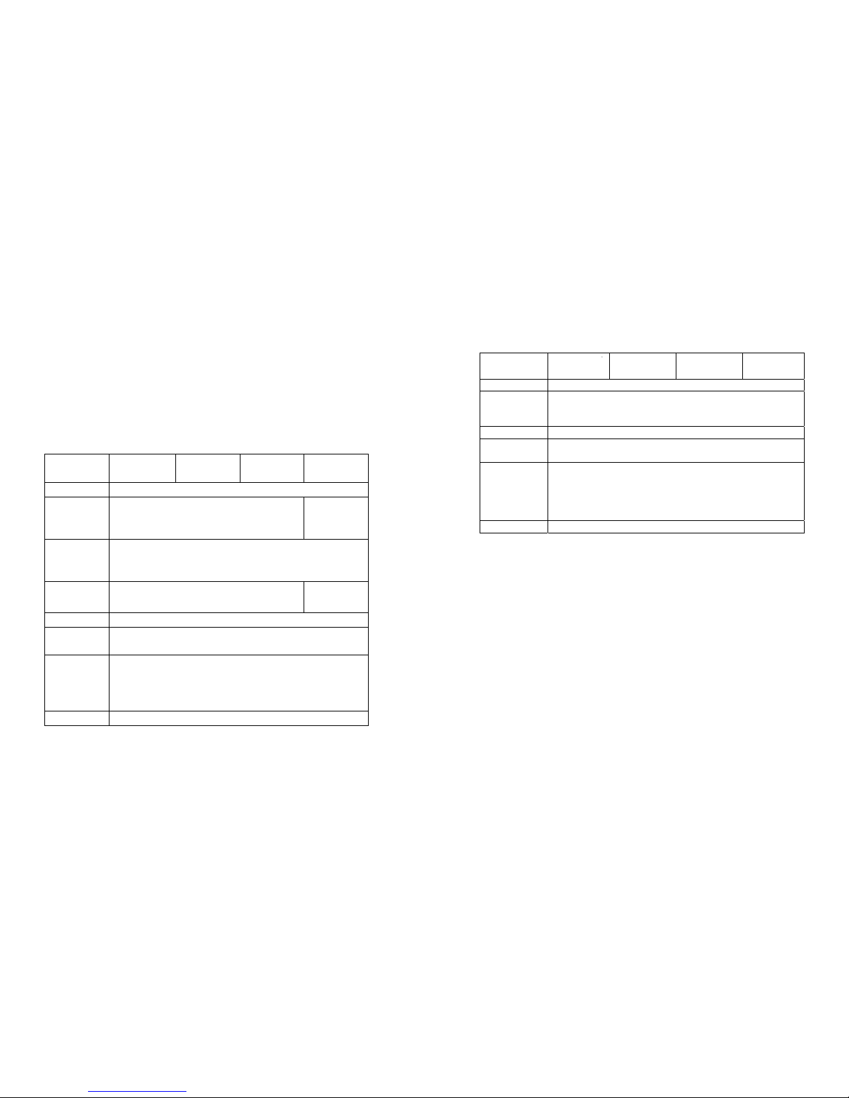
2. Fonts, Bar Codes and Graphics Specification
Printer Programming Language B, PPLB
Specification Model
OS-202DT
Model
OS-204DT
Model
AP 2.4
Model
OS-314TT
General fonts 5 fonts with different point sizes
Symbol sets
(Code pages)
8 bits: code page 437, 850, 852, 860, 863 and 865. 7
bits: USA, British, German, French, Danish, Italian,
Spanish, Swedish and Swiss.
Soft fonts Downloadable soft fonts
Font
expandability 1x1 to 24x24
Bar code
types
Code 39(checksum), Code 93, Code 128/ subset A,B,C,
Codabar, Interleave 2 of 5(checksum), Matrix 25, UPC
A/E 2 and 5 add-on, EAN-8/13, Code 128UCC,
UCC/EAN, Postnet, German Postcode. MaxiCode and
PDF417 (2D symbologies)
Graphics PCX and binary raster
The specifications of fonts, bar codes and graphics depend on the
printer interpreter. The emulation is a printer programming
language, through which the host can communicate with your
printer. There are two printer programming languages for models
202/204/214/314, they are PPLAand PPLB.
Printer Programming Language A, PPLA
Specification Model
OS-202DT
Model
OS-204DT
Model
AP 2.4
Model
OS-314TT
General fonts 7 alpha-numeric fonts, OCR A and OCR B ASD
Smooth fonts 6, 8, 10, 12, 14 and18 points 4, 6, 8, 10,
12, 14 and 18
points
Symbol sets
for fonts
smooth
USASCII, UK, German, French, Italian, Spanish,
Swedish, and Danish/Norwegian
Courier fonts 8 symbol set (PC, PC-A,PC-B EAMA-94,
Roman8, Legal,
Greek and Russian)
X
Soft fonts Downloadable PCL fonts
Font
expandability
1x1 to 24x24
Bar code
types
Code 39, Code 93, Code 128/subset A,B,C, Codabar,
Interleave 2 of 5, UPC A/E/2 and 5 add-on, EAN-8/13,
UCC/EAN-128, Postnet, Plessey, HBIC, Telepen and
FIM. MaxiCode and PDF417 (2D symbologies).
Graphics PCX, BMP, IMG and HEX formats
Notes :
1. The bare core for ribbon must be 11 cm in length. It should
have two opposite slits at two ends. If the ribbon itself is
less than 11 cm, it has to be aligned with the bare core at
left end when you install it.
2. Since this printer uses band buffer technology, if you just
print texts or barcodes the maximum length can be more
than 30 inches, whereas if you print many graphics the
maximum length can only be few inches under standard
onboard RAM.(The extension RAM, font board and flash
modules use the same connector, they cannot function at
the same time.)
53
54
Page 30
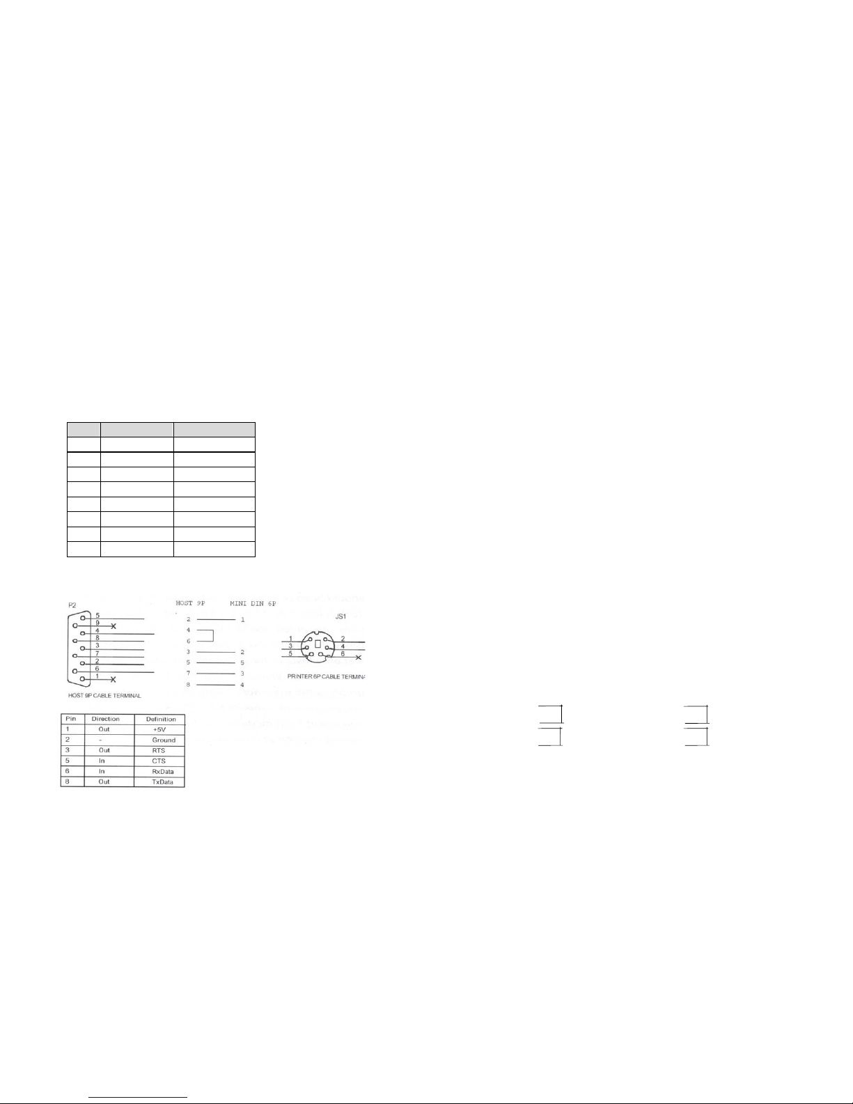
3. Interface Specifications
Note :
Pin 9 on AP 2.4 are reserved for
KDU(keyboard device unit), therefore do not connect these
pins if you are using a general host like a PC.
Serial
For Ap 2.4, the RS232 connector on the printer side is a
female, DB-9.
Connection with host:
Pin Direction Definition
1 In DSR
2 In RxData
3 Out TxData
5 - Ground
6 Out DTR
7 Out RTS
8 In CTS
9 Out +5V
Host 25S Printer 9P Host 9S Printer 9P
(PC or compatible) (PC or compatible)
DTR 20 …… 1 DSR DTR 4 …… 1 DSR
DSR 6 …… 6 DTR DSR 6 …… 6 DTR
TX 2 …… 2 RX TX 3 …… 2 RX
RX 3 …… 3 TX RX 2 …… 3 TX
CTS 5 …… 7 RTS CTS 8 …… 7 RTS
RTS 4 …… 8 CTR RTS 7 …… 8 CTS
GND 7 …… 5 GND GND 5 …… 5 GND
56
Alternatively you can just connect the 3 wires in the following way.
Host 25S Printer 9P Host 9S Printer 9P
(PC or compatible) (PC or compatible)
TX 2 …… 2 RX TX 3 …… 2 RX
RX 3 …… 3 TX RX 2 …… 3 TX
GND 7 …… 5 GND GND 5 …… 5 GND
pin 4 pin 4
pin 5 pin 6
pin 6 pin 7
pin 20 pin 8
55
Page 31

Parallel (Centronics)
The most simple way to connect to other hosts(not PC compatible) or
terminals is:
The parallel port is a standard 36-pin Centronics. Its pin
assignments are listed as following.
Printer Terminal/Host
Pin 2- RxData ……… TxData
Pin 3- TxData ……… RxData
Pin 5- Ground ……… Ground
Pin Direction Definition Pin Direction Definition
1 In /STROBE 13 Out SELECT
2 In Data1 14,15
NC
3 In Data 2 16 - Ground
4 In Data3 17 - Ground
5 In Data4 18NC
6 In Data5 19~30 - Ground
7 In Data6 31
NC
8 In Data7 32 Out /Fault
9 In Data8 33~36 - NC
10 Out /ACK
11t Out BUSY
12 Out PE
In general, as long as the data quantity is not too large and you
use Xon/Xoff as flow control, it will be problem free.
Baud rate: 2400, 4800, 9600, 19200 and 38400.
(programmable by command)
Data format : always 8 data bits, 1 start bit and 1 stop bit.
Parity : always non parity
Handshaking : XON/XOFF as well as CTS/RTS (hardware flow
control).
Auto Polling
If you run an application with the bundled printer driver under
Windows and use the serial port, you should check the above
Both the serial port and parallel port of this printer can be activated at
the same time, i.e the printer can simultaneously communicate with two
PC via different port. However as no port contention is made for this
printer, if both PC transmit data at the same time to this printer, the data
may become damaged in the receiving buffer.
parameters and set the flow control to "Xon/Xoff "or "hardware".
57
58
Page 32

Appendix I - Installing Dispenser Kit
4. ASCIITABLE
1. Turn off the printer power and unplug the printer.
NUL
0 @ P ' P
SON XON ! 1 A Q a q
STX
" 2 B R b r
XOFF # 3 C S c s
$ 4 D T d t
NAK % 5 E U e u
ACK
& 6 F V f v
BEL
‛
7 G W g w
BS
( 8 H X h x
) 9 I Y i y
LF
*
:
J Z j z
ESC + ;
;
K [ k {
FF
, < L \ 1 I
CR
- = M ] m }
SO RS
.
> N ^ n ~
SI US / ? O _ o DEL
2. Unwrap the PC bag of dispenser kit to take out the screw, the shaft,
the plastic roller, the dispenser bar, the direction label and the peeler
sensor cable.
Top Cover
3. Take off the top cover of the printer.
4. The peeler sensor cable has a sensor board at one end and a connector
at the other end.
5. Mount the two little holes of the sensor board on the two spines at
left upper corner inside the top cover, keeping the cable at the left.
59
60
Page 33
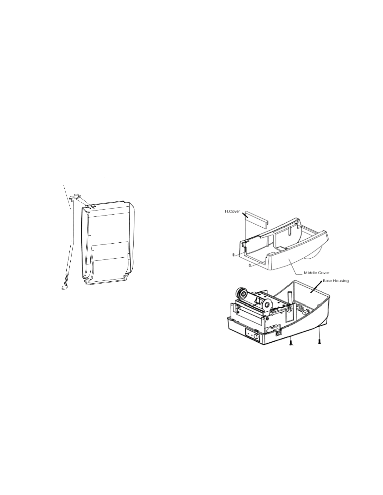
Middle Cover
6. Route the peeler sensor cable through the guides along the left side of
the top cover.
7. Fix the sensor cable and sensor board with Loctite-444 instant
adhesive or equivalent.
8. Release the two screws at the bottom of the base housing.
9. Remove the middle cover.
10. Take off the H Cover.
Sensor Cable
11. Tape the direction label on the top of the H cover with the arrow
sign heading toward the opposite of you.
61
62
Page 34
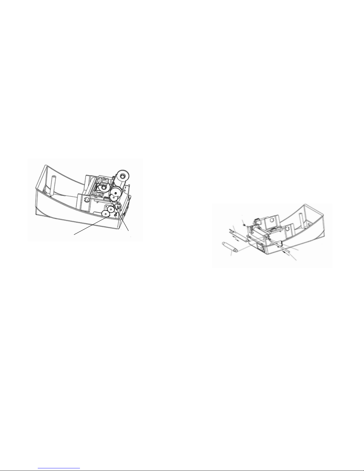
Base Housing
16. Hook the dispenser bar on the brackets of the chassis, positioning it
above the white roller. Ensure that the dispenser bar is paralleled
with the black platen roller and it's long thinner end is at the left.
12. Release the screw on the left bracket of the chassis.
17. Secure back the screw on the left bracket of the chassis.
18. Guide the sensor cable connector through the hole on the upper left
corner of middle cover.
Dispenser Bar
Screw
Bracket
Screw
White Plastic Roller
13. Unlatch the print head module. Hook the white roller on the
brackets of the chassis, ensuring the long thinner end at the left side.
14. Guide the shaft go through the respective holes on the left bracket,
the white roller, and the right bracket in order. (To smooth this
procedure, better hold the white roller with one hand.)
15. Secure the attached screw at right bracket of the chassis to fix the
shaft.
63
64
Page 35
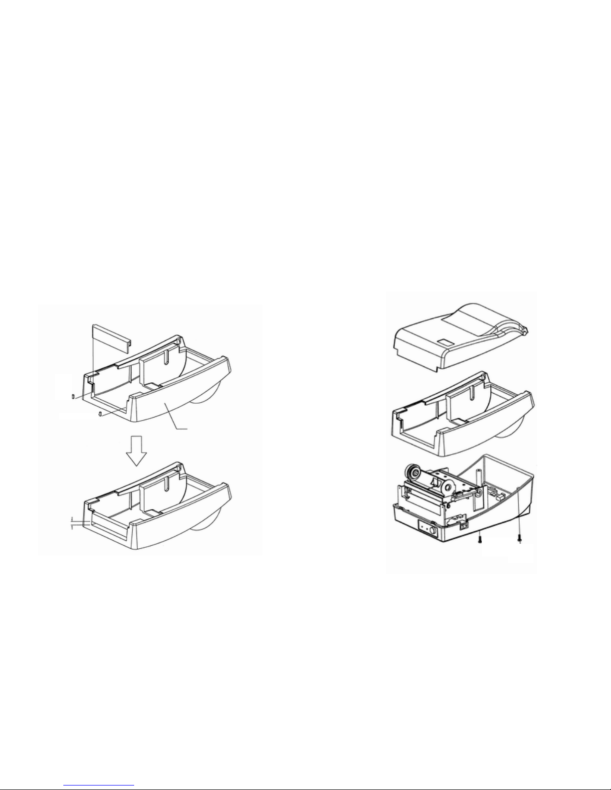
Appendix II - Installing the Cutter
19. Click the top cover back to the middle cover.
20. Insert the sensor connector into its receptacle on the main logic
board of the base housing.
1. Turn off the printer power, unplug the power cable and Centronics /
Serial cable.
21. Click the middle cover back to the base housing. First click in the
front part then the rear.
2. Remove the top cover.
22. Secure the two screws at the bottom of the base housing.
3. Remove two screws at base housing.
Middle Cover
4 mmGap
65
66
Page 36
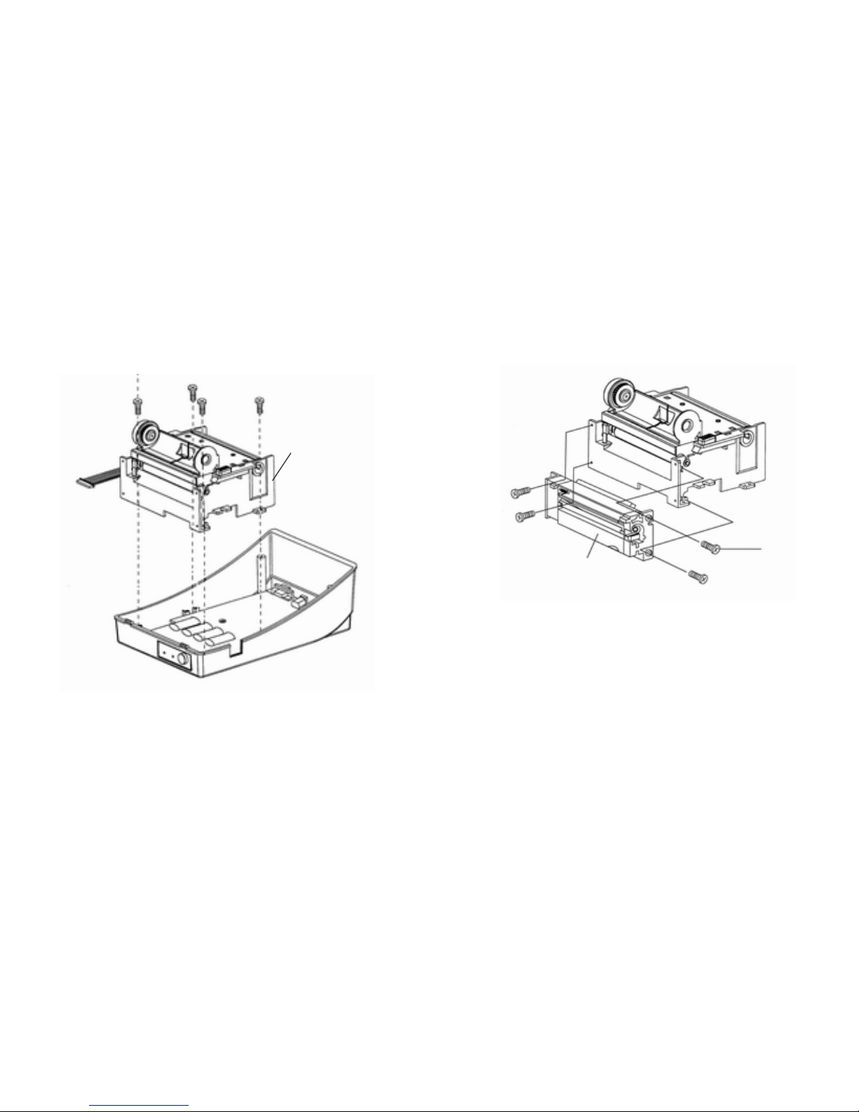
4. Remove the whole print head assembly by releasing 4 screws at its
feet.
5. Add a driver IC to U19 on the main board.
6. Secure four attached screws for the cutter.
Print Head Assembly
68
Cutter
7. Plug the cutter's connector into the PCB's header connector (JP13).
8. Reinstate the print head assembly by securing back the 4 screws.
9. Click back the middle cover.
10. Secure two screws back at base housing.
11. Click back the top cover.
67
 Loading...