

Page 1
A
usgabe 08/07
A
rtikelnummer: 0089999-06
Page 2

Page 3

Operators Manual
ALS 330/430
Release 8/07 Contents
Contents
1. Important Notes........................................................................................................5
1.1 Overview....................................................................................................................................... 5
1.1.1 Manufacturer...................................................................................................................... 5
1.1.2 Copyright............................................................................................................................5
1.2 Safety............................................................................................................................................6
1.2.1 General Safety Notes ........................................................................................................6
1.2.2 Warning Notes in the Text................................................................................................. 6
1.2.3 Operator’s duty of care...................................................................................................... 7
1.2.4 Concrete security regulations and symbols used.............................................................. 8
1.2.5 Security measures during normal operation......................................................................9
1.2.6 Security measures during maintenance and repairs......................................................... 9
1.2.7 Work on the electrical equipment .................................................................................... 10
1.2.8 Work on pneumatic equipment........................................................................................ 10
1.2.9 Observe environmental regulations.................................................................................10
2. Description .............................................................................................................11
2.1 Mechanics ..................................................................................................................................11
2.2 Operator panel............................................................................................................................ 13
2.3 Plug board.................................................................................................................................. 14
2.4 Electronics..................................................................................................................................15
3. Preparing the machine...........................................................................................17
3.1 Installation ..................................................................................................................................17
3.1.1 Unpacking of the unit....................................................................................................... 17
3.1.2 Connection of the machine.............................................................................................. 17
3.1.3 General setting ................................................................................................................17
3.2 Prepare dispensing.....................................................................................................................17
3.2.1 Insert material..................................................................................................................17
3.2.2 Define label data..............................................................................................................18
3.2.3 Capacitive label sensor....................................................................................................20
3.3 Label guide.................................................................................................................................21
3.4 Adjust dispense function.............................................................................................................21
3.4.1 Stop position....................................................................................................................21
3.4.2 Fixed dispensing speed................................................................................................... 22
3.4.3 Automatic dispensing speed (APSF)............................................................................... 22
3.4.4 Label position on the product...........................................................................................22
3.4.5 Product data bank............................................................................................................ 22
4. Operation ...............................................................................................................23
4.1 Safety recommendation..............................................................................................................23
4.2 Inserting label material ...............................................................................................................24
4.2.1 Removing label material.................................................................................................. 25
Page 4

Operators Manual
ALS 330/430
Release 8/07 Contents
4.2.2 Mounting a new label roll .................................................................................................25
4.2.3 Adjusting the pressure roller ............................................................................................27
4.2.4 Lead screw adjustment....................................................................................................28
4.2.5 Adjustment of the dispensing edge..................................................................................28
4.2.6 Printer adjustment............................................................................................................28
4.2.7 Adjust pressure roller.......................................................................................................29
4.3 Initializing new label material......................................................................................................29
4.4 Control of dispense unit..............................................................................................................30
4.4.1 Dispenser Menu selection................................................................................................30
4.4.2 Missing label function and web breaks............................................................................30
4.4.3 Display and data input......................................................................................................31
4.5 Maintenance ...............................................................................................................................34
5. Menu structure....................................................................................................... 37
5.1 Standard menu ...........................................................................................................................39
5.2 Extended standard menu............................................................................................................41
5.3 Product menu..............................................................................................................................47
6. Configuration menu................................................................................................43
6.1 Handling the menu......................................................................................................................44
6.2 Menu functions............................................................................................................................45
7. Serial interface....................................................................................................... 51
7.1 Data of the serial interface..........................................................................................................51
7.2 Interface commands ...................................................................................................................52
8. Connections and signals........................................................................................55
8.1 Output signals.............................................................................................................................55
8.1.1 Error and warning output..................................................................................................55
8.1.2 Printer output....................................................................................................................55
8.1.3 OD-Control output............................................................................................................55
8.1.4 Ready output....................................................................................................................55
8.2 Applicator modes........................................................................................................................56
8.2.1 Signals for direct dispense...............................................................................................56
8.2.2 Control signals for the ASA applicator.............................................................................57
8.2.3 Signals for the EP applicator............................................................................................58
8.2.4 Applicator connector ........................................................................................................59
8.3 Input signals................................................................................................................................60
8.3.1 Product sensor.................................................................................................................61
8.3.2 OD Control sensor ...........................................................................................................62
8.3.3 APSF sensor....................................................................................................................63
8.3.4 Control signals .................................................................................................................64
Page 5

Operators Manual
ALS 330/430
Release 8/07 Contents
8.4 EMI .............................................................................................................................................66
8.5 Electronic diagrams....................................................................................................................67
9. Errors and warnings...............................................................................................73
9.1 Dispenser error messages .........................................................................................................73
9.2 Dispenser warnings.................................................................................................................... 75
10. Technical specification...........................................................................................77
10.1 Technical Information................................................................................................................. 77
10.1.1 Application specification ..................................................................................................78
10.1.2 APSF- Sensor Specification (Optional function).............................................................. 78
10.2 Performance charts.................................................................................................................... 79
10.2.1 Charts 330 .......................................................................................................................79
10.2.2 Charts 430 .......................................................................................................................81
11. Adjustment.............................................................................................................85
12. Index ......................................................................................................................87
Page 6

Operators Manual
ALS 330/430
Release 8/07 Contents
Page 7

Operators Manual
ALS 330/430
Release 8/07 Page 5 Important Notes
1. Important Notes
1.1 Overview
The ALS 330 and 430 are fully automatic labeller. Handling is very easy and can be learned
with a minimum of training. For operation, only a few adjustments are necessary. The machine
is controlled by a microprocessor and because of its programmable functions, it can be used in
many applications.
Except of cleaning the rollers and the label sensor there is no periodical maintenance
necessary. This manual should help you to operate the machine. In chapter 3 the machine is
described and many expressions are explained. For normal operating chapters 4 and 5 are
important. All other chapters give additional details of the machine.
Note: This manual applies to ALS 330 and 430 machines, which are equipped
with firmware version 7.0.
For technical questions, particularly in case of problems, your local service organisation will be
pleased to help you.
1.1.1 Manufacturer
This machine was built by:
Avery Dennison Deutschland GmbH
Ohmstraße 3
85386 Eching
Germany
Tel. +49-08165-925-0
FAX +49-08165-3143
1.1.2 Copyright
© 2007 Avery Maschinen GmbH. All rights reserved. No part of this work covered by Avery's
copyright may be reproduced or copied in any form or by any means (graphic, electronic or
mechanical, including photocopying, recording, recording taping, or information and retrieval
systems) without the written permission of Avery Maschinen GmbH. Avery also reserves all
other rights, including the right to make changes or corrections at any time without notice.
Avery make no representation or warranties about the accuracy, currency, completeness or
suitability of the information provided herein and will not be held liable for any use of this
information for any purpose. It is provided "as is" without express or implied warranty.
Page 8

Operators Manual
ALS 330/430
Release 8/07 Page 6 Important Notes
1.2 Safety
1.2.1 General Safety Notes
In order to avoid any risk of injury due to squeezing between the fixed dispensing edge and the
passing product, it may be necessary to add a protection cover in front of the dispensing edge.
The necessity for this has to be decided on case by case.
See also regulation EN 292 and 294.
1.2.2 Warning Notes in the Text
In this description, two types of notes can be found:
y
Warning note – indicates a possible risque of injury for the user. Ignoring the warning can
lead to injuries or material damages.
Example:
CAUTION! - The machine is connected to mains. Only authorised
personnel may open the cover. Operation without this cover is not
allowed.
y
Special advice regarding the carrying out – please notice!
Example:
Note: Please take note of the given notes and advices. They serve your safety
as well as the preservation of value of the machine.
Page 9
Operators Manual
ALS 330/430
Release 8/07 Page 7 Important Notes
1.2.3 Operator’s duty of care
The machine was designed and constructed taking into account a
hazard analysis and after careful selection of the harmonised
standards to be observed, as well as other technical specifications.
Thus, it corresponds to the state of the art and allows the highest
possible degree of safety during operation.
The safety of the machine, however, can only be put into operating
practice if all measures required for the safety are taken. It falls within
the operator‘s duty of care to plan these measures and to verify their
implementation.
Above all, the operator must make sure that
• the machine is only used in accordance with its purpose (cf. the
section “Use in accordance with the purpose” in the chapter
“Specification”)
• the machine is only operated in faultless serviceable condition
and that especially the safety devices are regularly checked with
respect to their serviceability
• the required personal protective clothing and equipment for
operating, maintenance and repair personnel are available and
are being used
• a legible and complete copy of the operating instructions is always
available at the place of operation of the machine
• only personnel which is qualified and authorised for it will operate,
service, and repair the machine
• this personnel is instructed in all relevant issues of occupational
safety and environmental protection on a regular basis and is
familiar with the operating instructions and especially the safety
instructions contained therein
• all safety and warning instructions on the machine itself are not
removed and are legible
Page 10
Operators Manual
ALS 330/430
Release 8/07 Page 8 Important Notes
1.2.4 Concrete security regulations and symbols used
In the following operating instructions, concrete security regulations are indicated in order to
point out the remaining risks which cannot be avoided when operating the machine. These
remaining risks include danger to
• Persons
• Product and machine
• Environment
The symbols used in the operating instructions are above all intended to point out the security
regulations!
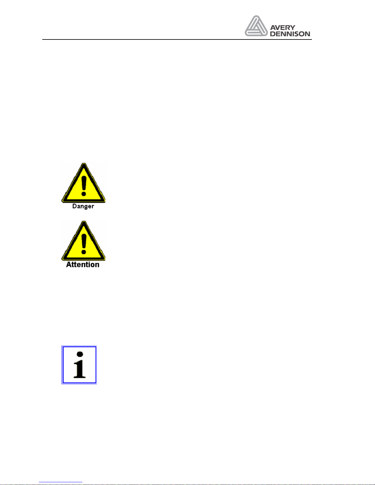
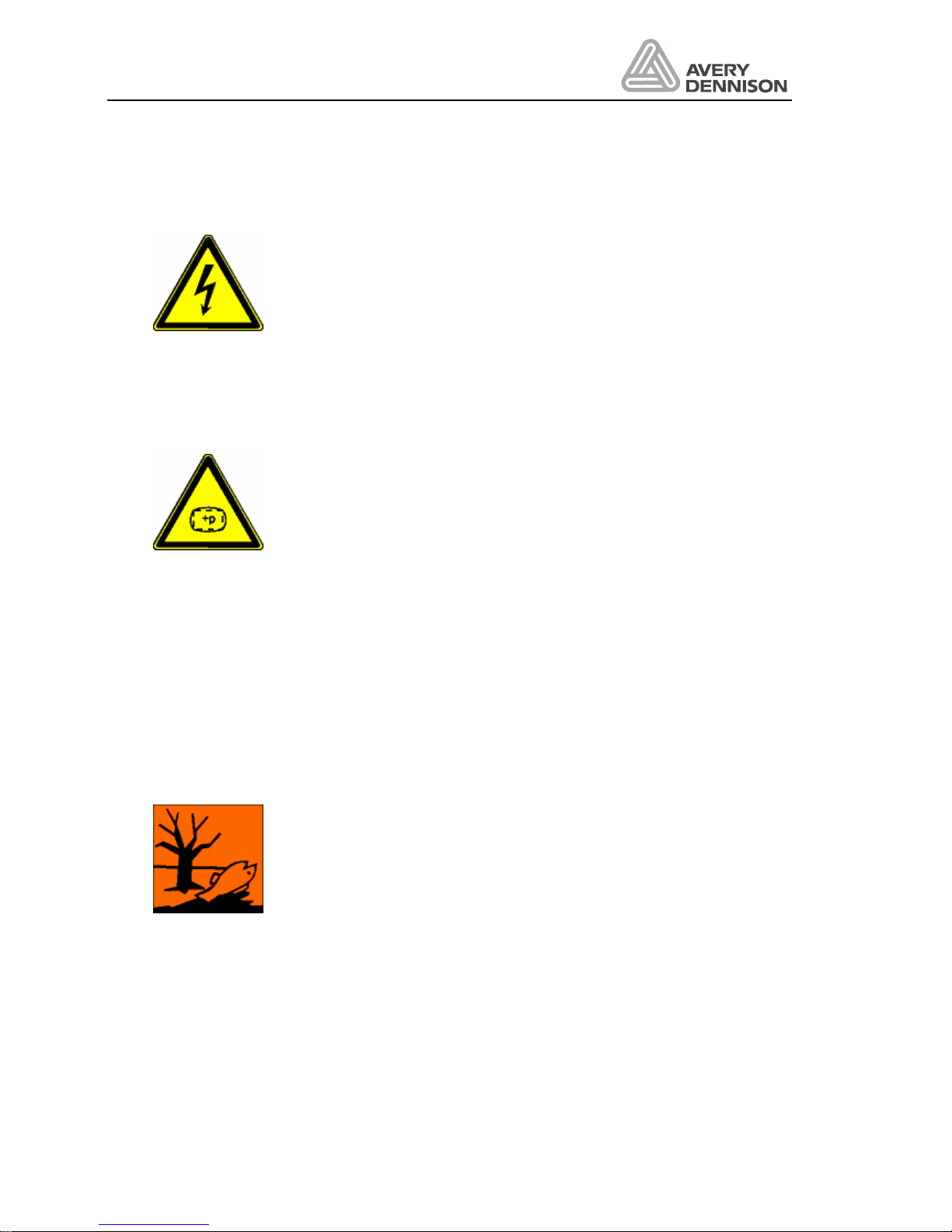
This symbol indicates that especially danger to persons has to be
expected.
(Lethal danger, danger of injury)
This symbol indicates that especially danger to the machine, material,
and the environment has to be expected.
The most important aim of the security regulations is to avoid injuries to a person.
• Whenever there is a warning triangle with the caption “Danger” in front of a security
regulation, dangers to the machine, materials, and the environment are not excluded.
• Whenever there is a warning triangle with the caption “Warning” in front of a security
regulation, a danger to persons, however, must not be expected.
The symbol used in each case, however, cannot replace the text of the security instruction.
Thus, it is necessary to always read the text completely!
This symbol does not indicate security regulations, but provides
information for a better understanding of the machine’s operations.
Page 11
Operators Manual
ALS 330/430
Release 8/07 Page 9 Important Notes
1.2.5 Security measures during normal operation
The machine may only be operated by trained and authorised
persons who are familiar with the operating instructions and are able
to work in accordance with it!
• Before starting the machine, check and make sure that
• only authorised personnel is staying in the operating area of the
machine
• Nobody can get hurt when the machine is started!
• Before every production start-up, the machine must be checked
for visible damage and it must be made sure that it is only
operated in faultless working condition! Any defects found must
be immediately reported to the supervisor!
Before every production start-up, all materials/objects that are not
necessary for production must be removed from the operating area of
the machine!
Before every production start-up, it must be checked and made sure
that all safety devices function in a correct manner!
1.2.6 Security measures during maintenance and repairs
Inspection and maintenance periods laid down in the operating
instructions must be observed!
Observe maintenance and repair instructions in these operating
instructions, which refer to individual components!
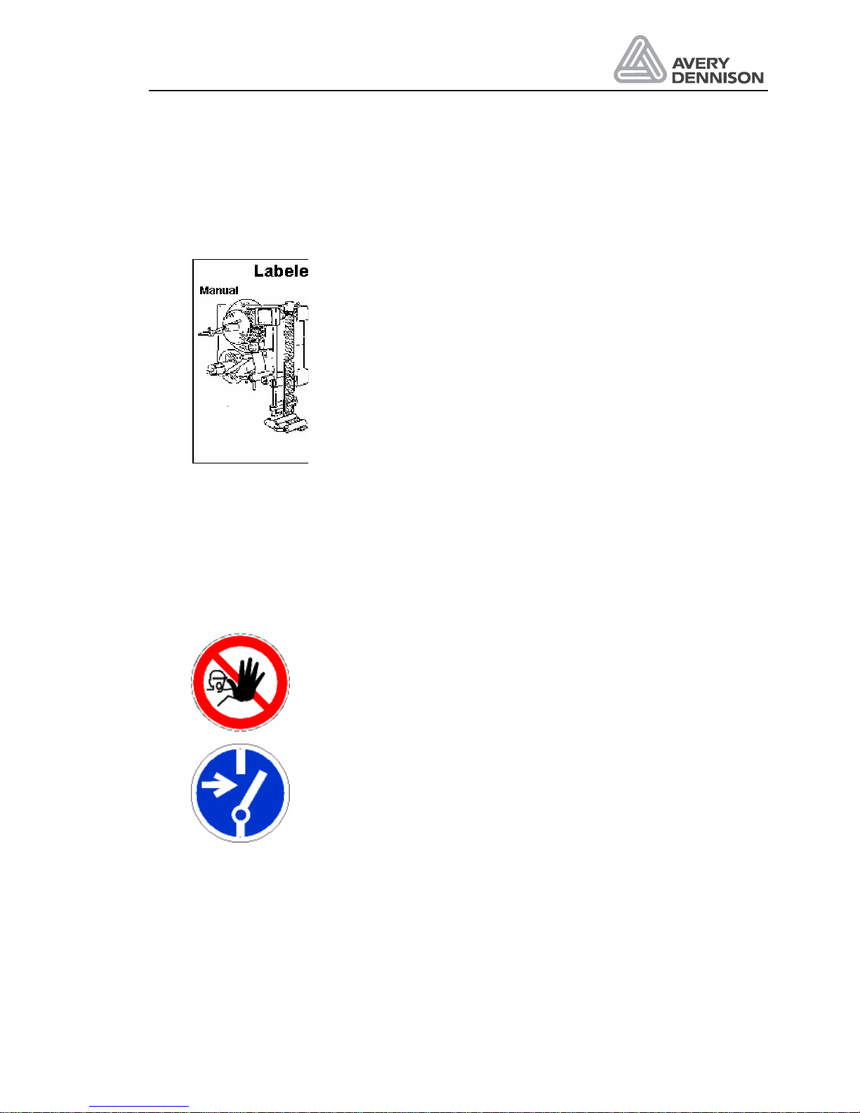
Before performing maintenance and repair work, the access to the
operating area of the machine must be prohibited for unauthorised
personnel! Post or put up a sign, which indicates the maintenance, or
repair work!
Before performing maintenance and repair work, turn off the main
switch for the electric power supply and secure it with a padlock!. The
key to this padlock must be in the hands of the person who performs
the maintenance or repair work!
When exchanging heavy machine parts, use only suitable and
faultless load suspension devices and stopping devices!
Page 12
Operators Manual
ALS 330/430
Release 8/07 Page 10 Important Notes
1.2.7 Work on the electrical equipment
Repair work on the electrical equipment of the machine may only be
performed by a trained electrician!
Electrical equipment must be checked on a regular basis!
Loose connections must be fixed again!
Exchange damaged lines/cables immediately!
Always keep the switch cabinet closed! Access is only allowed to
authorised personnel with keys/tools!
Never wash down switch cabinets and other housings of electrical
equipment with a water hose for cleaning!
1.2.8 Work on pneumatic equipment
Maintenance and repair work on pneumatic equipment may only be
performed by specially trained personnel!
Before starting maintenance and repair work, depressurise the
pneumatic equipment of the machine!
By way of precautionary maintenance, exchange hose pipes on a
regular basis, even if there is no damage to be detected!
(Observe the manufacturers’ instructions!)
Before setting into operation after maintenance or repair works
• check if loosened screwed connections are tight
• make sure that removed coverings are re-installed
After termination of maintenance and repair work and before restarting the production, make sure that
• all materials, tools, and other equipment required for maintenance
and repair work are removed from the operating area of the plant
• all safety devices of the plant function in a faultless manner!
1.2.9 Observe environmental regulations
During any and all work on and with the machine, the statutory duties
concerning prevention of waste and the proper waste
disposal/recycling regulations must be observed.
Especially in the case of installation, repair and maintenance work,
substances which are hazardous for the water, such as detergents
containing dissolvents, may not pollute the soil or get into the sewage
system!
These substances must be stored, transported, collected, and
disposed of in appropriate containers!
Page 13

Operators Manual
ALS 330/430
Release 8/07 Page 11 Description
2. Description
CAUTION! - The machine is connected to mains. Only authorised personnel
may open the cover. Operation without this cover is not allowed.
This chapter explains the structure and the function of the labeller. The expressions used are
explained here.
2.1 Mechanics
The labeller is available in a right-hand or a left-hand version. The expression right or left is
related to the direction of product transport.
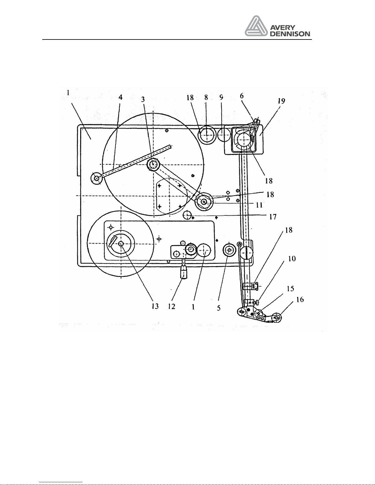
The material is unwound from the label roll (3). The maximum diameter of the label roll is 300
mm. The width of the backing paper is 155mm for a 330 and 230mm for a 430 machine. The
label roll is guided by a swing away lever (4).
The dancer arm (011) keeps the material tight and the acceleration forces low. The deviator
roller (8) allows the use of inside or outside wound label web. The deviator roller (9) guides the
material to the dispensing edge. Paper brake brush (6) applies a brake force to the label web
and keeps the label web under a certain tension without disturbing the movement. At the
dispensing edge (10) the label sensor (15) is mounted. It detects the gap between the labels.
The sensor includes a light source and a light receiver. The software can adjust the sensitivity.
With this information, the machine calculates the position of the label. At the dispensing edge
(10) the label is separated from the backing paper and moved to the product. With a foam roller
(16) in front of the dispensing edge, the label is applied to the product.
The deviator rolls (5) guides the backing material to the drive roller (1).
The drive roller (1) moves the label web according to the adjusted dispensing speed.
The pressure roll (12) has to be positioned in the centre of the label web, in order to guide the
web straight on track. By means of the knurled screws, the pressure roller is held in its required
lateral position on the shaft.
With its handle the pressure roller (12) will be opened and closed. When inserting the material
the pressure roller has to be opened.
The deviator roller (17) guides the backing paper to the rewind mandrel (13). The rewind
mandrel should always be set to expanded position when mounting a new roll of labels. This
allows an easy removal of the collected backing material.
To ensure a reliable run of the label web the guides (18) have to be adjusted according to the
width of the labels in use.
Page 14
Operators Manual
ALS 330/430
Release 8/07 Page 12 Description
Figure 1 Machine layout
Apart from the drive roller (1), and the material brush (6) the labeller has no mechanical
wearing parts.
The operator panel (19) is described in the next section of this chapter.
Page 15
Operators Manual
ALS 330/430
Release 8/07 Page 13 Description
2.2 Operator panel
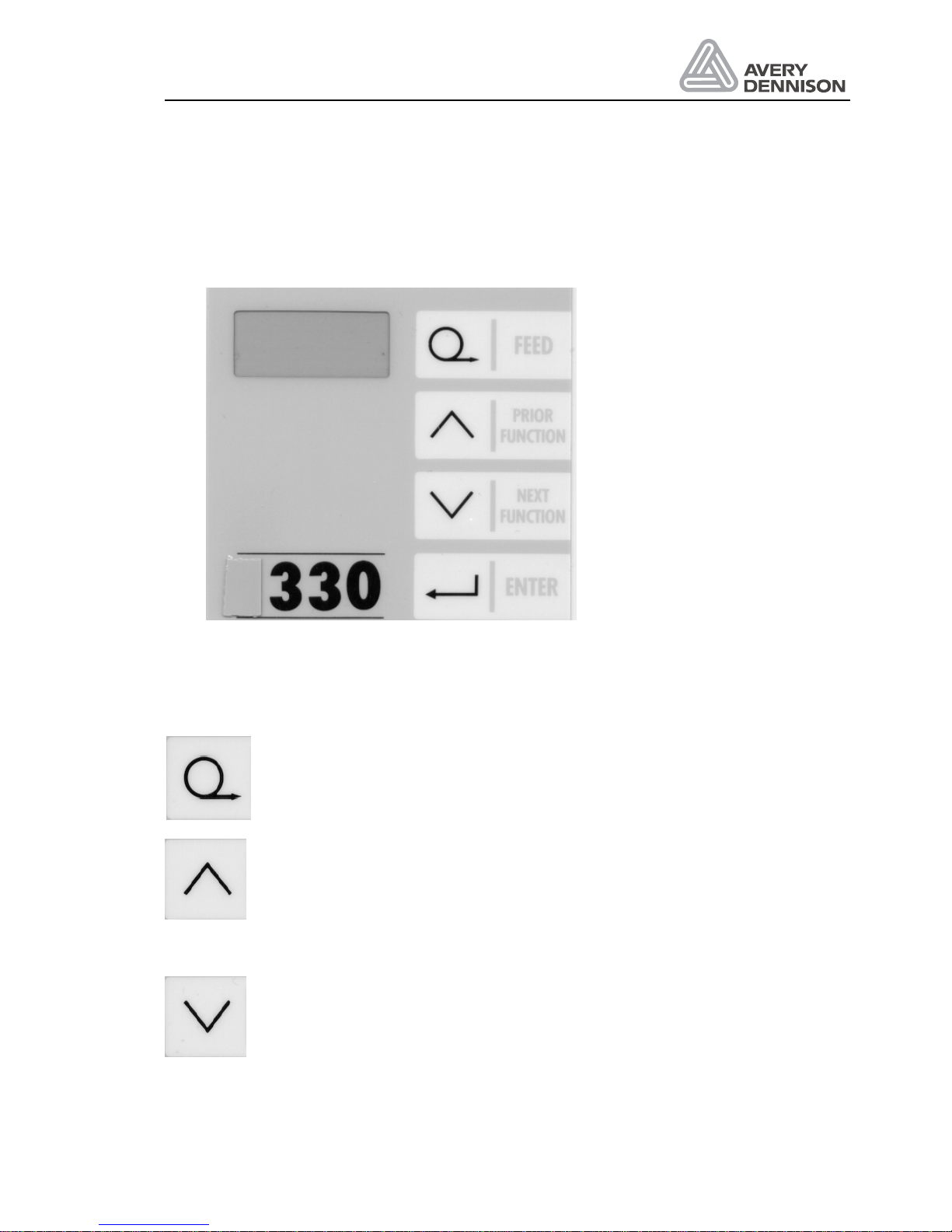
The operator panel (Figure 2) of the 330/430 is shown below, it has a 4 digit LED display and 4
membrane keys.
Figure 2 Operator panel
The 4 membrane keys have following functions:
FEED: By pressing this key one label will be dispensed. When the machine
displays INIT pressing this key will start initialisation of the machine. An
initialisation has to be made each time a new material is used. If the FEED key is
pressed and held as the machine is turned on then the machine carries out an
automatic initialisation of the label parameters "CONT" and "LPIT".
PRIOR: This key moves up the menu or increases the value of a (Prior function)
parameter. If the up arrow key is pressed and held as the machine is turned on
the product menu is selected.
NEXT: This key moves down the menu or decreases the value of a (Next
function) parameter. If the down arrow key is pressed and held as the machine is
turned on the standard menu is selected.
Page 16
Operators Manual
ALS 330/430
Release 8/07 Page 14 Description
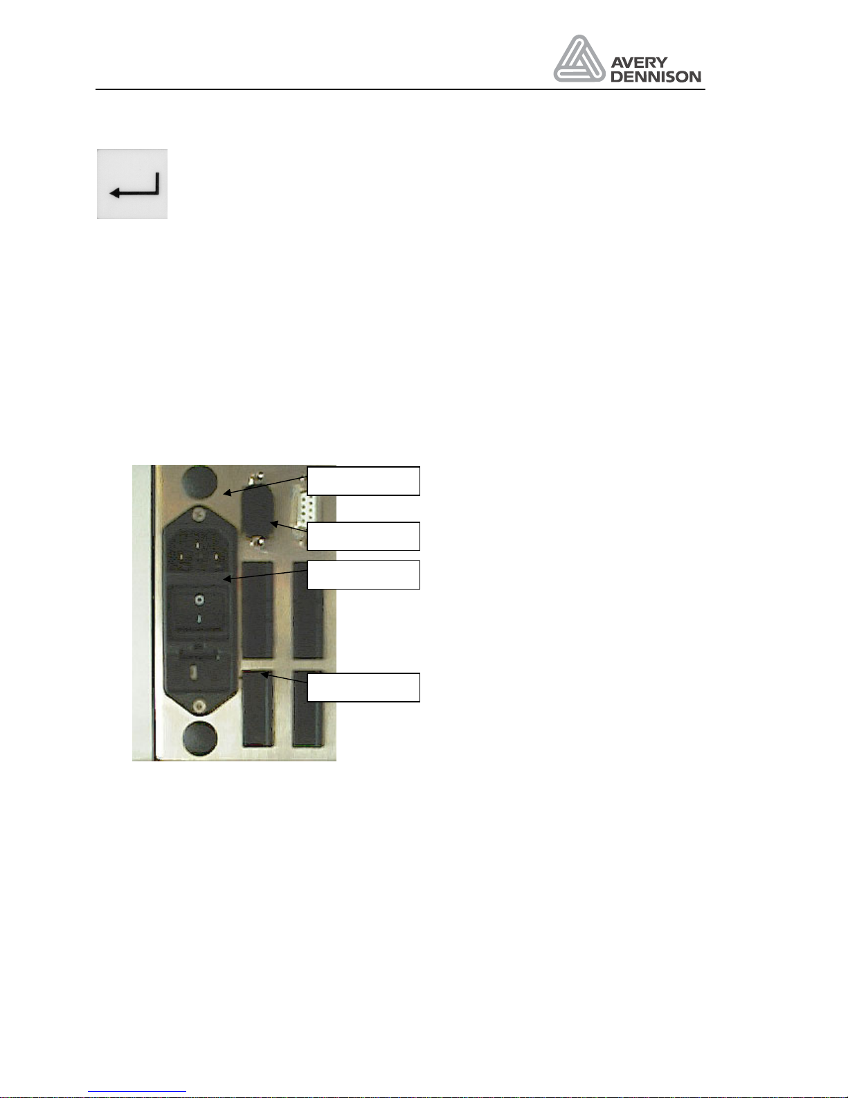
ENTER: This key is used to enter or exit a menu point or to cancel a warning or
error message.
When the keys have different meanings, it will be explained in the relevant menu description.
2.3 Plug board
The plug board is shown in Figure 3. Beside the mains switch and the mains cable socket there
are some more holes for optional functions. Standard execution in this machine is one I/O plug
prepared for the product sensor. The connection of the other plugs is described in chapter
Connections.
If you use the optional connections, it is strongly recommended to do this by means of the
optional available SUB-D connectors. This ensures best EMI stability of the machine.
Figure 3 Plug board
The fuse holder setting you have to select according to your local main voltage (100, 120, 220
or 240 V). You carry this out by taking off the fuse holder and position the fuse holder insert
accordingly.
Product
APSF-Sensor
Applicator
SPS control
Page 17

Operators Manual
ALS 330/430
Release 8/07 Page 15 Description
2.4 Electronics
As standard the complete electronic is integrated in the machine. For special requirements
(water protection e.g.) a machine version the electronic is housed in a separate cabinet is
available.
As standard the complete electronic is integrated in the machine. For special requirements
(water protection e.g.) a machine version the electronic is housed in a separate cabinet is
available.
Page 18

Operators Manual
ALS 330/430
Release 8/07 Page 16 Description
Page 19

Operators Manual
ALS 330/430
Release 8/07 Page 17 Preparing the machine
3. Preparing the machine
In this chapter you will learn how to install and adjust the labeller. After this step has been
completed you will be ready to learn how the labeller's parameters can be adjusted to suit your
particular production requirements.
3.1 Installation
3.1.1 Unpacking of the unit
• For removing the unit off the box, don’t hold the machine on the dispensing edge to prevent
disadjustment off the machine.
• For mounting the machine, a complete system of holding tools is available. Ask your
representative.
• Take care that the machine is safe and stable mounted.
• There are rotating parts on the machine. Do the necessary actions to prevent that anybody
can be caught from these parts.
3.1.2 Connection of the machine
Before connecting the machine to the mains, check the correct setting of the line voltage. For
the connection of sensor, applicators e.g. see the chapter connections. Fix all cables to prevent
accidents and damaging of cables. Have also a look to the EMI chapter for proper machine
operation.
For checking of correct operation of sensors, applicators use the check functions SCHK, I_CH
and O_CH.
3.1.3 General setting
Normally the setting is done, but before operation check and note the general dispenser
configuration: dispenser direction, machine type, applicator mode, and APSF function.
3.2 Prepare dispensing
3.2.1 Insert material
Insert your label material in the machine to follow the instructions in the chapter Operation /
Threading.
Page 20

Operators Manual
ALS 330/430
Release 8/07 Page 18 Preparing the machine
3.2.2 Define label data
For correct dispenser operation, you have to tell the machine the length of the label and adjust
the label sensor. Normally this is done automatically. For this follow the instructions in chapter
Operation / Initialise material.
There are some reasons the automatic initialisation is not possible:
1. Using another then the standard optical label sensor
2. Label material with a low contrast ratio between label and backing paper
3. Labels with holes inside the label
In this case, you have to set one or both of the parameter manually.
Activate the extended standard menu to do the settings by:
y
Pressing both keys NEXT and PRIOR simultaneously
Display: CODE
y
Password CODE entering:
1 time pressing the key PRIOR FUNCTION
2 times pressing the key NEXT FUNCTION
3 times pressing the key ENTER
Display: LPIT
y
Setting the label length
Enter the LPIT function by pressing ENTER. Measure the distance from one label edge to
the edge of the next label. Enter the value in mm by using the function keys. Press ENTER
to leave the function. See also the information below.
y
Change the setting of the label sensor
If another label sensor then the Wenglor type will be used, call the CONT function and set
the value to any manual value (e.g. M006.).
If the contrast ratio is low, follow the instructions to adjust manually contrast.
y
To store the setting permanent leaves the menu with the QUIT function. If you power off the
machine without quit all modification are lost.
y
By pressing the key FEED one label can be dispensed if you are in the parameter selection.
Page 21
Operators Manual
ALS 330/430
Release 8/07 Page 19 Preparing the machine
Setting LPIT manually
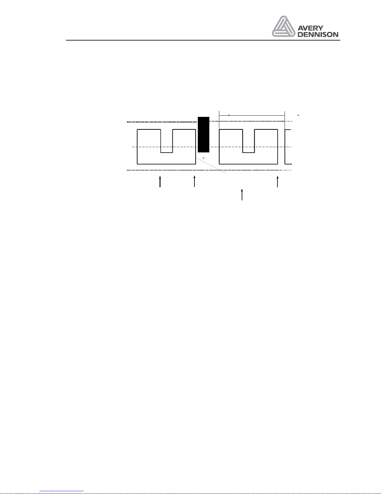
To initialise labels with cut outs such as the one shown below - the "LPIT" parameter should be
used to enter the label pitch of the label web.
Sensor signals
Label sensor
LPIT
real leading
edge of label
Figure 4 Definition of LPIT
All other label edges seen by the label sensor will be ignored until the distance adjusted in the
"LPIT" parameter has been fed through the label sensor.
Manual adjustment of the CONT parameter
y
Remove a label from the backing paper and slide it inside the sensor.
y
Reduce the value with the PRIOR key until the LED switched on.
y
Press the key NEXT until the LED switched off. If there are marks an the backing paper do
the measurement on this position.
y
Note the value GAP xxx
y
Slide the backing paper including label inside the sensor. Use the lightest position on the
label for the adjustment.
y
Increase with the NEXT key the value until LED lights again. Note the second value GAP
yyy
y
Calculate the contrast value by the formula (xxx + yyy) / 2 and set it.
y
Manual adjustment is completed.
With a difference of less than 20 an operation with this kind of sensor is not possible
(sometimes two or more labels are dispensed).
Page 22
Operators Manual
ALS 330/430
Release 8/07 Page 20 Preparing the machine
3.2.3 Capacitive label sensor
For transparent labels the standard photo label sensor doesn’t work. In this case, use a
mechanic or a capacitive label sensor.
Note: For correct automatic initialisation, the CONT parameter has to be set to a
manual value, if you using not the standard photo sensor.
A mechanical sensor is limited in the speed. The bounce at the label edges produces wrong
signals.
There is optional a capacitive label sensor available (Leuze GK14/24L).
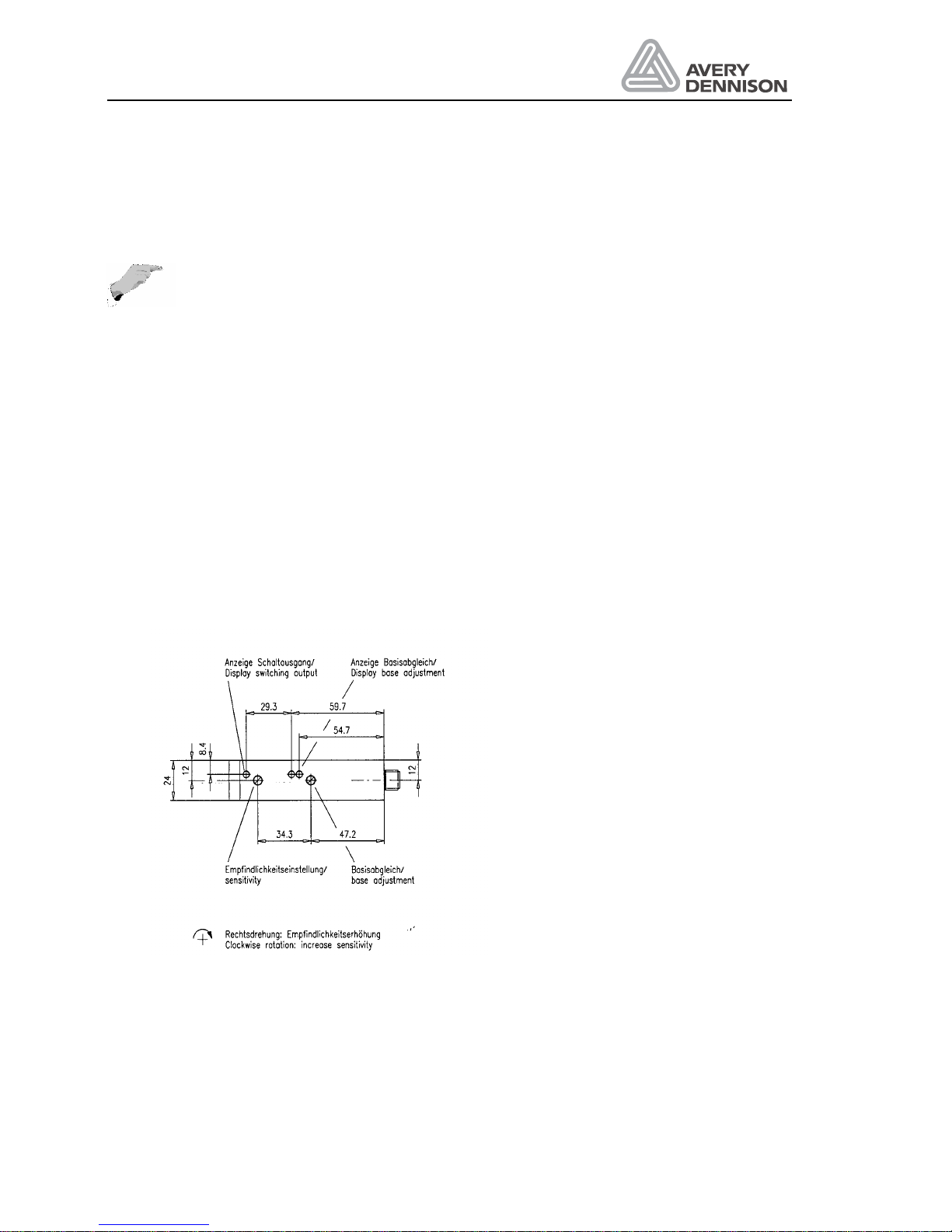
Adjustment of the sensor is carried out as follows (Figure 5):
1. Set sensitivity to maximum by turning the Potentiometer clockwise. Then rotate ½ turn
anticlockwise.
2. Remove label material out of sensor.
3. Perform base adjustment, that both LED “base adjustment” have the same brightness.
4. Put label with backing paper inside the sensor. Doing this, the LED “switch output” and the
left LED “base adjustment” are switched off. With backing paper only in the sensor both
LED are switched on. If the LED are lightning with label inside the sensor, increase
sensitivity in ¼ turn steps by rotating the sensitivity clockwise.
5. Check the adjustment over the complete length of label.
Carry out the above adjustment after mounting, cleaning or increasing sensitivity.
Figure 5 Capacitive sensor
Page 23

Operators Manual
ALS 330/430
Release 8/07 Page 21 Preparing the machine
3.3 Label guide
On some of the axles, they’re guiding clamps. Adjust the clamps near the machine so all have
the same distance to the front plate (31.5mm). The outer clamps should be mounted that the
guide but not bend the label material.
The front of the V-dispensing edge has a rot, which can be adjusted for straighten the material
guiding. Spend several labels by pressing the dispenser FEED key. If the material guiding is
running out of the guiding way, adjust the rot by loosing two screws at the dispensing edge.
With a L-dispensing the adjustment is done by move the tail sheaves behind the dispensing
edge.
3.4 Adjust dispense function
For an operation without any trouble and high label accuracy, tree adjustments are required:
• Label position on the dispensing edge: stop position
• Dispense speed
• Label position on the product
The adjustment should be done in the same order, because parameter like the stop position
depends on the setting of the stop position and the dispensing speed.
3.4.1 Stop position
The first step is to adjust the stop position. This is the basic adjustment of the dispense
process. Also in case of problems with the machine check if the stop position is okay.
Figure 6 Stop position
The stop position should be adjusted so that the label stops at the dispensing edge up to 3 mm
behind.
For a correct operation of the automatic label compensation, they will compensate a missing
label on the web, first the distance between label sensor and dispensing edge has to be
defined. Do this by calling the DIST function in the configuration menu. Check the setting by
removing a label before the label sensor from the web. Give a start signal to the machine by
triggering the start sensor (not the FEED key) and see if the compensation is done on the right
position. Do the fine adjustment with the STOD function.
Page 24

Operators Manual
ALS 330/430
Release 8/07 Page 22 Preparing the machine
3.4.2 Fixed dispensing speed
The second step is to adjust the dispense speed. If an APSF sensor is used see 3.4.3.
If an applicator is used, then the dispense speed has no influence to the dispense process.
Continue with 3.4.4.
Set POS to the distance between start sensor and dispensing edge. If installed remove the
roller to press the label onto the product. Now try to dispenser one product. If the label has
wrinkles reduce the speed VELO. If the product peels out the label, so the stop position of the
next label is different to the last position increase the speed. Normally your dispense speed
should be a little bit higher than your product speed.
3.4.3 Automatic dispensing speed (APSF)
With a connected rotary encoder, the dispensing speed follows the measured product speed.
To adjust the speed use the EGRA function located in the extended standard menu. The
measured speed will be displayed in the VELO function. Do the adjustment in the same way
described for fixed speed.
3.4.4 Label position on the product
At least adjust the position of the label on the product with the POS function or with the STAD
function, if an applicator is in use.
3.4.5 Product data bank
Save your setting in one of the product data banks. If different products and / or labels are in
use up to nine different combinations could be stored. Define and store the different product
data. The select the product data bank mode by holding the PRIOR key during power on.
Switch back to normal mode by holding the NEXT key.
Page 25

Operators Manual
ALS 330/430
Release 8/07 Page 23 Operation
4. Operation
This chapter describes the operation of the machine.
4.1 Safety recommendation
CAUTION!
y
Before connections to the mains check the correct voltage selection.
y
Use only original spare parts for service.
y
Open of the cover is only allowed authorised personal.
y
Handling of the machine is permitted only trained personal.
y
Be careful on operation, fingers, hair, clothes, jewellery, etc. may be caught
by and get into rotating axles.
Page 26
Operators Manual
ALS 330/430
Release 8/07 Page 24 Operation
4.2 Inserting label material
Attention:
• Before threading the new material, the waste paper should be removed.
CAUTION! - Isertion/exchange of material should be carried out only by
especially instructed personal.
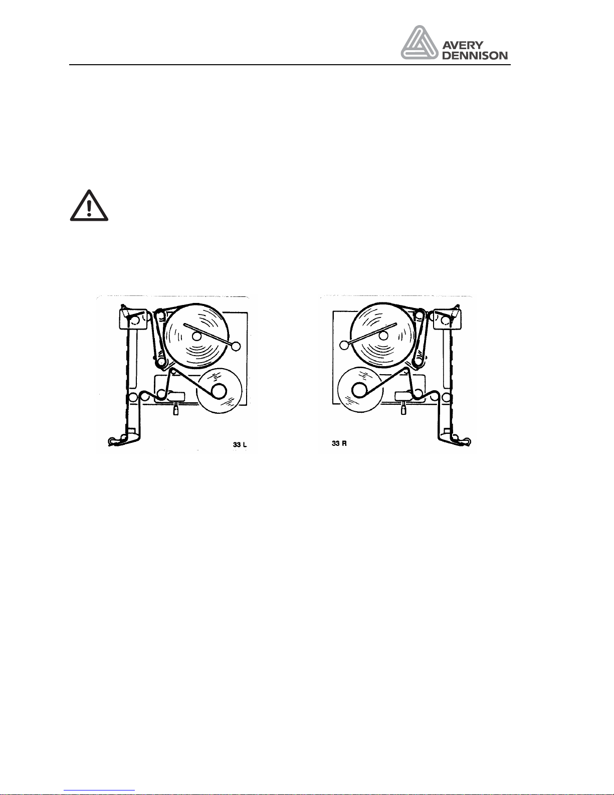
Threading of the label material is shown down below on the threading diagrams for the
right-hand and the left-hand version.
Left hand version Right hand version
Figure 7 Threading diagram
Page 27
Operators Manual
ALS 330/430
Release 8/07 Page 25 Operation
4.2.1 Removing label material
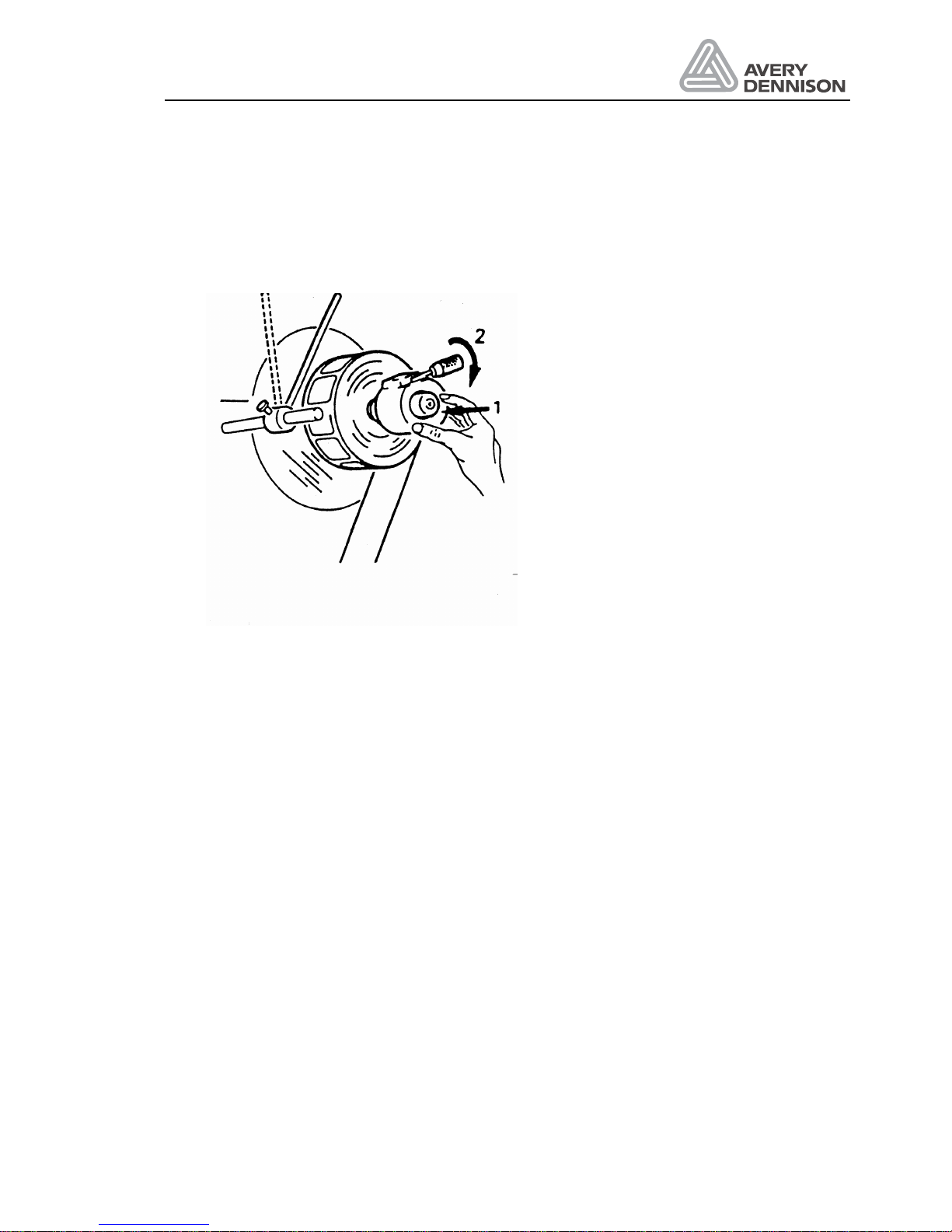
Before you mount a new roll of labels, it is necessary to remove the accumulated roll of backing
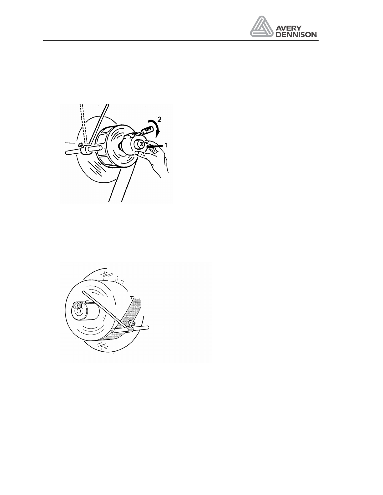
material. Turn the lever the expanding pads retract. The roll of backing material can easily be
pulled off the rewind mandrel.
Figure 8 Remove label material
To ensure a reliable function of the unwind it is important to exchange the collected backing
material each time you mount a new label roll.
4.2.2 Mounting a new label roll
Mounting of the new label roll depends on the used machine
Page 28
Operators Manual
ALS 330/430
Release 8/07 Page 26 Operation
Mounting a new label roll on ALS 330 Euro
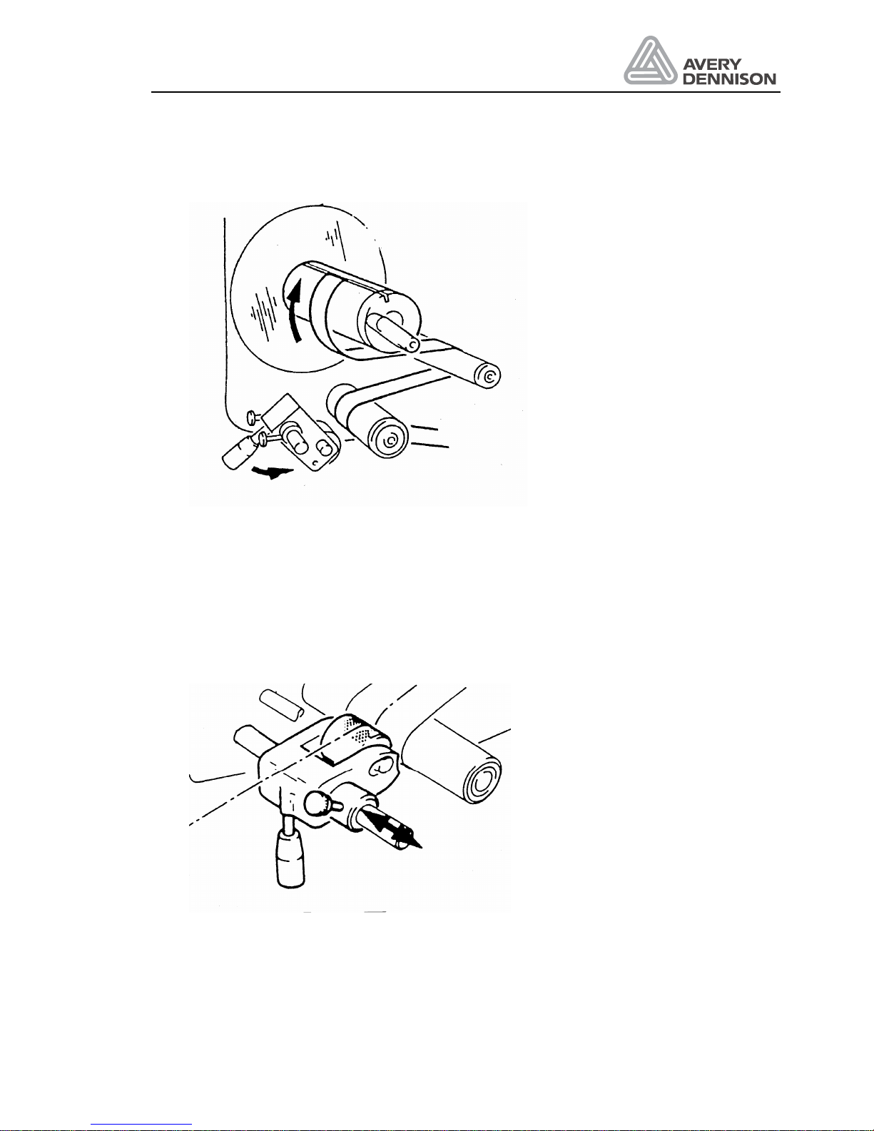
Mount the new label roll to the unwind mandrel and secure the position by means of the unwind
clamp. You achieve a reliable position of the unwind clamp by pressing it firmly against the
label roll core, while you are moving the lever 2 to the locking position.
Figure 9 Unwind unit at ALS 330 Euro
Mounting a new label roll on ALS 430
By means of the knurled screw the collapsible key can be moved further in or out for clamping
and releasing the label roll.
Figure 10 Unwind unit at ALS 430
The material brush has to be positioned in a way, that the material is kept tight. From time to
time, it is recommended to reverse the mounting of the brush while you are loading a new label
roll. Mount the label web through the label sensor. Remove the labels until about 50 cm of the
backing material is exposed. Thread this backing material around the drive and deviator roller.
Fold the end of the backing material back approximately 15 mm and insert the leading edge
into the slot of the rewind mandrel. Turn the lever, the rewind expands, the slot is closed and
Page 29
Operators Manual
ALS 330/430
Release 8/07 Page 27 Operation
the backing material is clamped in the slot. Wind the mandrel a few times to take up any
backing material slack between the deviator roller and the rewind mandrel.
Figure 11 Rewind
4.2.3 Adjusting the pressure roller
The pressure roller should always be positioned over the middle of the backing material. This
ensures accurate label placement. Turn the pressure roller away from the drive roller. Loosen
both knurled screws. Move the entire unit to its correct position. Fasten the screws securely
again.
Figure 12 Pressure roller
Page 30
Operators Manual
ALS 330/430
Release 8/07 Page 28 Operation
4.2.4 Lead screw adjustment
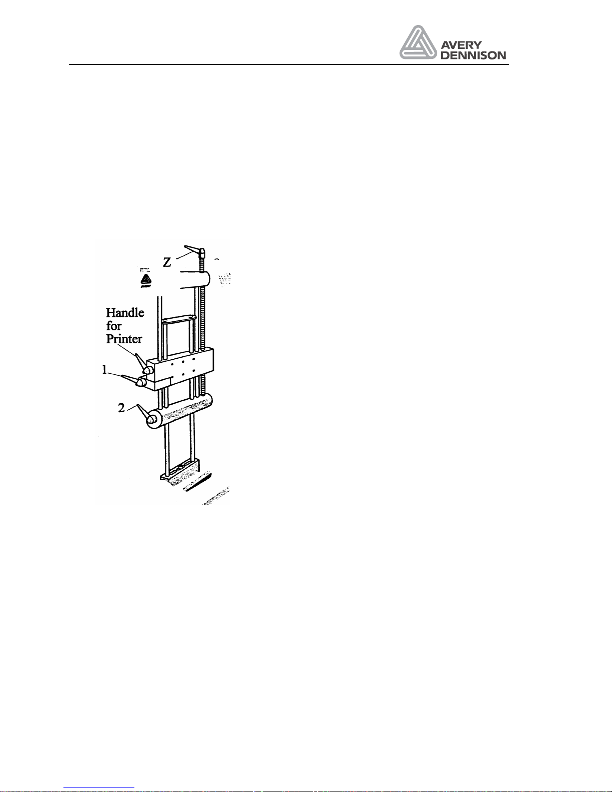
For adjustments of the dispensing edge towards or away from the conveyor, the lead screw
integrated in the labelling head should be used. Positions can be read from the scale on the
dispensing edge bars.
4.2.5 Adjustment of the dispensing edge
Loosen handle 1 and 2 and turn lead screw Z. Once the adjustment is completed pull the
handles tight again.
Figure 13 Dispensing edge
4.2.6 Printer adjustment
If your labeller is equipped with a printer, you adjust the print position as well with the lead
screw Z. In this case loosen handle (orange) for printer and handle 1. Once the adjustment is
completed, pull the handles tight again.
Page 31
Operators Manual
ALS 330/430
Release 8/07 Page 29 Operation
4.2.7 Adjust pressure roller
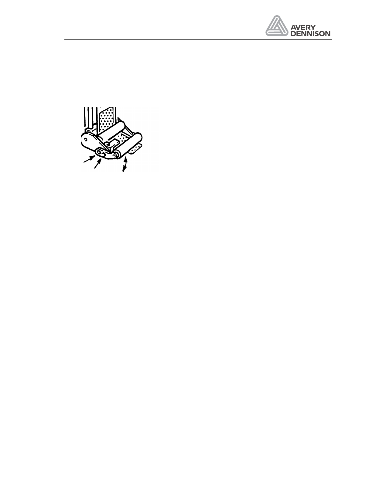
Depending on the application the foam roller has to be adjusted. Loose the both screws and
tighten the screws again after the adjustment was done.
Figure 14 Adjust pressure roller
4.3 Initializing new label material
The machine requires data of the label material in use i.e. label length and opacity of the label
and backing material. In most cases, those parameters can be scanned during automatic
initialisation. This is not always possible.
During initialisation, the machine uses its label sensor to determine where the labels are on the
label web and the distance between the leading edge of labels (the label pitch) so that they can
be positioned correctly.
There are several modes of initialisation:
y
Automatic mode: The machine measure the setting
y
Manual mode: The operator measures the label parameter and keys in the values.
In most cases, initialisation should be executed in fully automatic mode. For fully automatic
initialisation, the "LPIT" and "CONT" parameters should be set to "AUTO". Initialisation can be
executed by pressing the <FEED key> whenever the message "INIT" is displayed by the
machine.
The message "INIT" is displayed in the following cases:
a) if the <FEED> key is pressed and held during power up
b) on return to the standard menu after the "CONT" or "LPIT" parameters have been changed
to automatic mode
c) on return to the standard menu after the configuration menu has been used
d) after clearing the error messages E__0 or E__1 in the standard menu. (If the feed key is
pressed while another parameter is displayed, the data from the last initialisation is held
and the first label edge detected is simply moved to the position defined by the "STOD"
parameter)
To start initialisations simply press the <FEED> key when "INIT" is displayed.
The machine will slowly feed the label web while it searches for the gaps between labels and
measures the label pitch. When the machine has determined this information it will move the
Page 32
Operators Manual
ALS 330/430
Release 8/07 Page 30 Operation
first label edge found during the initialisation process to the position that has been adjusted with
the "STOD" parameter. After initialisation has been completed successfully, "ON" is displayed.
Initialisation can only take place in the standard menu; it is not required in the product menu
since all label data is already stored in the machine's memory. After a E__0 or E__1 message
has been cleared whilst in the product menu the first label edge detected at the next press of
the <FEED> key will be moved to the position defined by the "STOD" value stored in the
machine's memory.
However, when changing to a new product bank or changing label rolls the FEED key should
be pressed once so that the label sensor can find the next leading label edge and move it to the
correct dispense position previously defined by the STOD parameter
4.4 Control of dispense unit
4.4.1 Dispenser Menu selection
Turning on the mains switch and at the same time pressing one of the panel keys, you may
select between several options:
PANEL KEY
& mains switch
Function Display message
FEED Material initialisation INIT
NEXT FUNCTION Standard menu ON
PRIOR FUNCTION Product menu PD0n
ENTER Configuration menu CODE
Press the key as long as the display shows the version number. One of the above mentioned
messages appears in the display. Calling the product menu is only possible, if at least one
product bank has been programmed.
If you do not press a panel key while turning on the machine the same menu is active that has
been used before the machine was switched off.
4.4.2 Missing label function and web breaks
The missing label function stops the label web in the correct position even when a label is
missing from the label web. If there are more than 3 missing labels from the web then the
machine will stop and give the correct message E_1.
If the label web has broken or come to an end then the machine will no longer be able to find
the next leading label edge and so after more than 3 signals from the product sensor the error
message E_1 will also be generated.
Page 33
Operators Manual
ALS 330/430
Release 8/07 Page 31 Operation
4.4.3 Display and data input
The operator panel controls the operation of the machine. Data can be displayed and changed.
The displays have different meanings:
y
Parameter selection:
In the display a parameter is shown, e.g. POS, STAD, or PD02 (product menu no. 02). By
pressing the keys FUNCTION another parameter can be selected. By pressing the key
ENTER the data is displayed.
y
Data display:
The display shows the values of the parameters (e.g. 0123) or possible adjustments e.g.
(AUTO). Pressing the FUNCTION keys changes the data value. By pressing the key
ENTER the data input is completed and a new parameter is shown.
y
Error display:
If the display shows e.g. E__XX, the dispenser has recognised an error. A warning is shown
by W_XX. As soon as the error has been corrected, you may erase the message by
pressing the key ENTER and you will get back to the status the machine was in before the
error was indicated.
Note: Data entered in the standard menu are not stored, if the machine is switched off. If you
need to store data you have to use the extended menu. Please check if it is of help for you
using the product menu in your application.
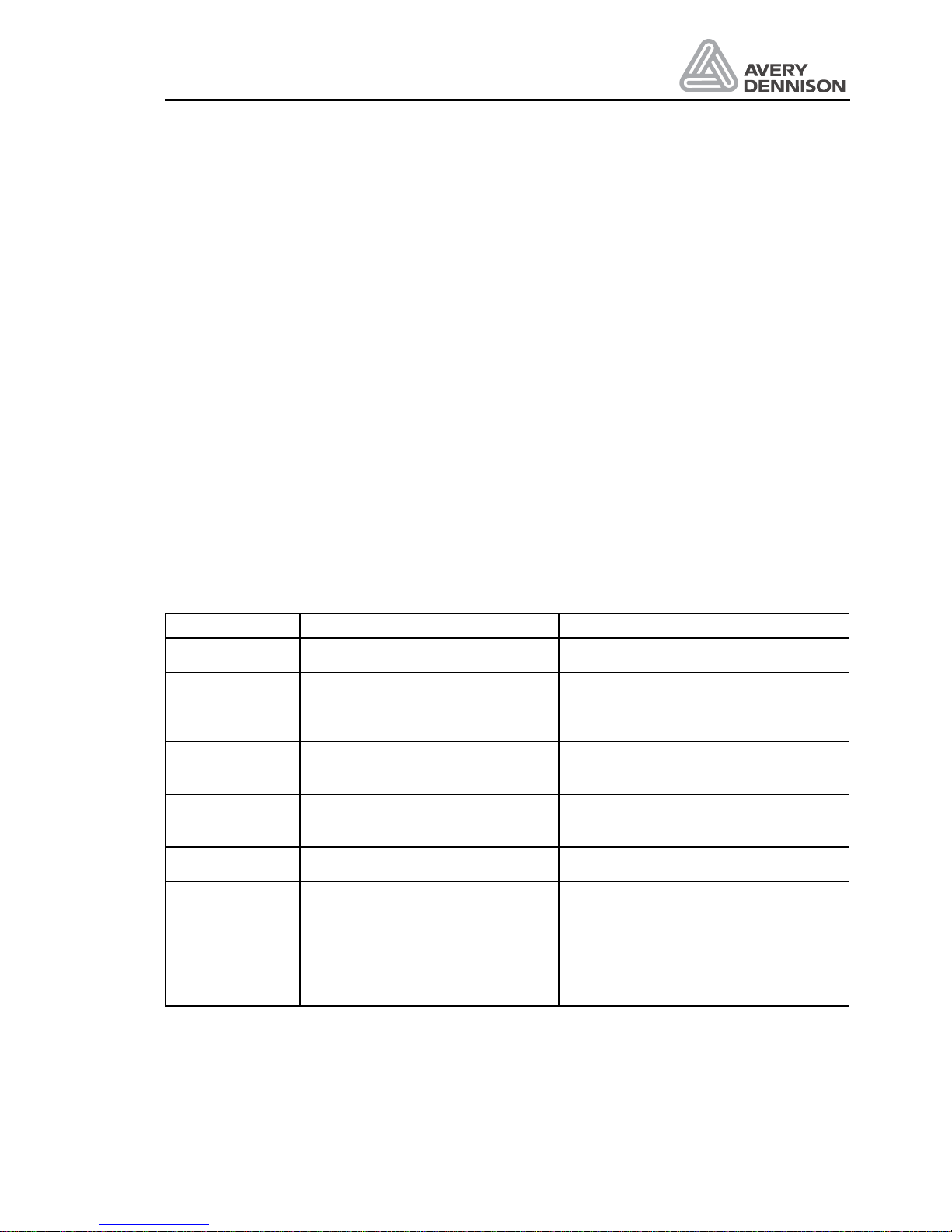
Display Menu function Function data value
ON Labeller ready
OFF Label function suspend
POS label position on product Up to 999.9 mm
STOD Label stop position at the
dispensing edge
Depends on setting of DIST, Label
length and RAMP
VELO Dispensing speed ALS 330: 0.2 ... 25.0 m/min
ALS 430: 0.2 ... 18.0 m/min
STAD delay time before labelling starts 0,1 ... 999,9 ms
BLOW apply time 0,1 ... 999,9 ms
INIT Initialisation of label material
(CONT and LPIT are measured
according to label size)
Appears after E__0, E__1 and Power
on + FEED key depressed, or if the
values of CONT and LPIT are
changed
Dispenser active ___________________________________________________ON
The dispenser is able to dispense labels.
Page 34
Operators Manual
ALS 330/430
Release 8/07 Page 32 Operation
Dispenser stopped ________________________________________________OFF
The dispenser function is stopped. Single labels could be dispensed with the FEED key.
Material initialisation_______________________________________________ INIT
A new initialisation of material is necessary. Pressing the FEED key will start the initialisation.
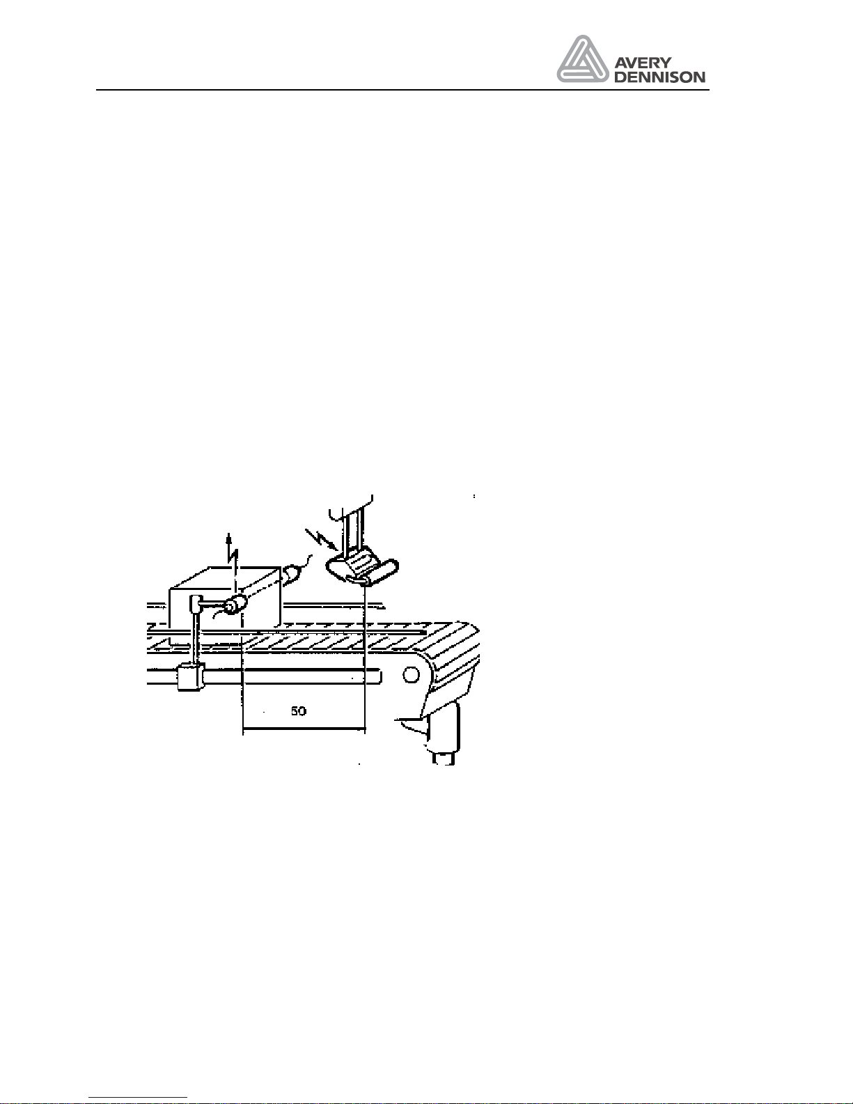
Label position ____________________________________________________POS
The position of the label can be changed by the parameter POS while the machine is in
operation. The display is presented in 1/10 mm and means the distance between product
sensor and labelling position of the product. The display value 0500 would mean 50.0 mm. By
pressing the key PRIOR the value is increased, i.e. the label is put on later. By pressing the key
NEXT FUNCTION the value is decreased and the label is put on earlier.
The labelling position is also changed by variation of the product speed. In this case first control
you product speed and the dispense speed VELO. Only if both speed matches adjust the
position with the POS function.
Figure 15 Label position
Page 35
Operators Manual
ALS 330/430
Release 8/07 Page 33 Operation
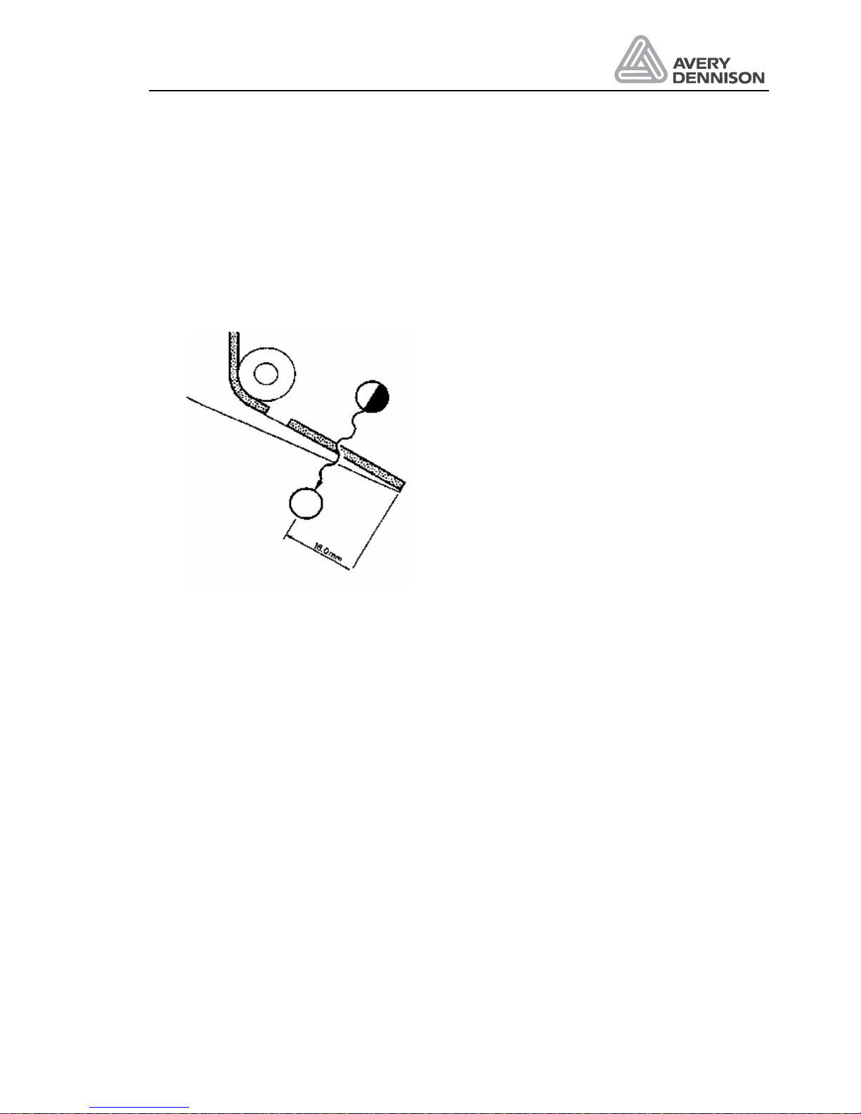
Stop position ___________________________________________________ STOD
The stopping position (STOD) defines the position where the label stops after it has passed the
label sensor. The value represents 1/10 mm. In the example 0160 has to be adjusted by
pressing the FUNCTION keys. If an increased value is chosen, the label is advanced further, in
case of decreased values the position is closer to the label sensor.
Figure 16 Stop position
Dispense speed __________________________________________________VELO
The speed value VELO displays the dispensing speed in 0.1 m/min. The product conveyor
speed has to be constant to assure accurate labelling. A change of the product speed causes a
different position of the label on the product. In case of inaccurate labelling, it should be
verified, if the speed of the dispenser and your product match together. This is done
automatically if the optional automatic speed follower (APSF) is installed.
If the machine is equipped with an applicator, two parameters in the standard menu can be
changed. The delay time which specifies the moment when the applicator must put the label
onto the product and the blow time - how long the applying of the label should take.
Start delay_______________________________________________________STAD
By the aid of the parameter STAD the period of time between the recognition by the product
sensor and the dispensing of the label onto the product is determined. The time units are ms,
the time is adjusted by the keys FUNCTION.
Page 36

Operators Manual
ALS 330/430
Release 8/07 Page 34 Operation
Blow on time ___________________________________________________ BLOW
The labelling time BLOW indicates, for how long the applicator should apply the label onto the
product. This time is displayed in ms also. BLOW is equivalent to APT2, which is found in the
extended menu.
Product menu____________________________________________________ PD0n
This menu can be used for storing data for different labels and products. 15 different sets of
product data can be programmed.
If you want to switch to another product, select the respective product number by pressing
NEXT and PRIOR, then press ENTER. Now the new product data are activated.
To change the labelling parameters you can call the extended menu. After leaving this menu,
your product data will be automatically updated.
The labeller carries out the labelling of your products completely automatically.
Check now and then:
• if there is still enough labelling material on the unwind roll
• if an error has been displayed and the machine no longer effects labelling
• if the label is placed correctly onto the product. If this is not the case, correct the respective
parameter in the standard menu.
Control is even simpler if you use an OD-control. The OD-sensor measures the diameter of the
material roll and indicates a warning message W__5 as the label roll diameter gets too small,
i.e. there are only a few labels left on the label roll. To the warning output, you may connect an
alarm indicator, an optical or acoustic signal can be triggered.
4.5 Maintenance
The machine can be easily maintained and has only a few wear parts. If you change the
material, note if any glue or waste labels are stuck on the rolls or dispensing edge. In this case
you have to clean the respective parts. The machine has to be cleaned at least once a week.
Glue and waste labels have to be removed from the rollers, the dispensing edge, the material
brush, and possibly from the applicator. All rollers have to be cleaned from any grease. We will
supply a special cleaning set for this. The material label sensor has to be cleaned from dust
regularly. The material brush should be turned around whenever the material is changed. Any
glue has to be removed from the brush. If there is a soft roller at the dispensing edge for
applying the label to the product, check if the roller is damaged or dirty. Replace it if necessary.
The unwind has to operate in such a way, that the dancer arm does not bounce to its end
position. If this is not the case, the friction mechanism has to check.
If the backing paper is not wound up accurately, the belts have to be tightened.
Check the electrical connections, especially the mains cable for unreliable connection.
Page 37

Operators Manual
ALS 330/430
Release 8/07 Page 35 Operation
Page 38

Page 39

Operators Manual
ALS 330/430
Release 8/07 Page 37 Menu structure
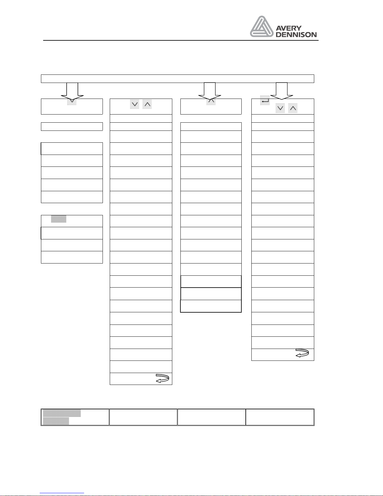
5. Menu structure
The touch panel keys or the optional interface can change labeller parameters. The last
entered parameters are the actual ones the machine works with. Programming via the interface
is described in chapter Serial interface.
There are 2 levels for parameter adjustments. The first one is for parameter selection. With the
keys FUNCTION a parameter is selected. By pressing the keys ENTER the second level can
be reached. Pressing the keys FUNCTION can change the parameter values. By pressing
ENTER you quit the parameter adjustment and the next menu point is shown. For some
functions the change of values is effected immediately, for others when leaving the menu point.
Details in the menu functions.
There are 4 different menu structures:
• Standard menu
This menu is used for normal operation. The most important parameters for the production
can be changed here. The adjustments are lost after turning off the machine.
• Extended standard menu
This menu offers additional parameters and functions to those in the standard menu. Any
adjustments made in the extended menu are stored on quitting the menu and are
maintained even if the machine is then turned off.
• Product menu
If data banks are stored in the extended menu, the product menu can be activated. In this
menu, programmed data banks only can be selected. Changing parameters in this menu is
not possible. When storing data in a new data bank, the current adjustments are saved to
the new product data bank. You may change data values of a stored data bank by loading
the data from the extended standard menu, modifying them and resaving them in a data
bank.
• Configuration menu
In this menu, you configure the machine according to your applications. Additionally you
have access to service test functions. This menu is mainly dedicated to service technicians.
All current parameter settings are stored on quitting the configuration menu and are
maintained if the machine is then turned off.
Page 40
Operators Manual
ALS 330/430
Release 8/07 Page 38 Menu structure
Power On
at power on
+
at power on
at power on
or
+
CODE CODE
Standard menu Extended menu Product menu Configuration
INIT/ON/OFF INIT/ON/OFF INIT/ON/OFF
Direct LPIT PD01 DTST
INIT/ON/OFF CONT PD02 P_S_
POS SENS PD03 MACH
STOD STOD PD04 MDIR
VELO PRDL PD05 MLAB
POS PD06 APSF
Ô Applicator Ô STAD PD07 APPL
INIT/ON/OFF VELO PD08 I_CH
STAD STST PD09 O_CH
BLOW SLEW PD10 FACT
! EGRA PD11 BAUD
Ô APT1 PD12 PARI
Ô APT2 PD13 SBIT
Ô APT3 PD14 DBIT
Ô APT4 RECY
ASTP
DIST
SAVE
LABC
LOAD QUIT
PDT
QUIT
Direct
dispense
Ô Applicator
active
! APSF on only if Baud
not set to NONE
Page 41
Operators Manual
ALS 330/430
Release 8/07 Page 39 Menu structure
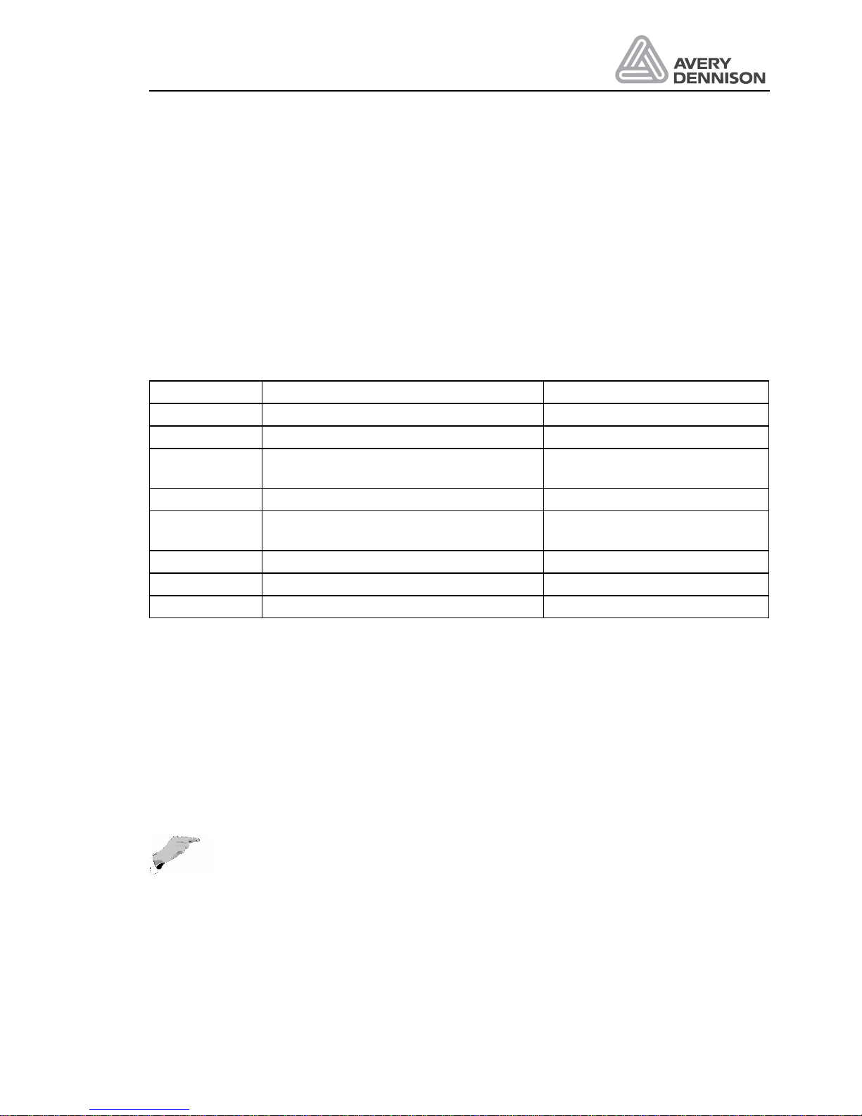
5.1 Standard menu
Usually this menu is used for labelling. All important parameters can be changed while the
machine is running. After turning power on, the standard menu is active, unless the product
menu was on before the machine was switched off.
If the product menu is active and you want to use the standard menu, switch off the machine
again. Press the key NEXT FUNCTION while switching on the machine and the standard menu
is active. In the standard menu you have access to all important parameters for labelling. The
number of parameter and its kind depends on how the configuration has been made. Change
of parameters is active immediately. Changed values are lost when turning off power. If values
need to be stored, the extended standard menu has to be used. All available commands are
listed down below.
Display Function Values
ON Normal operation
OFF Stop labelling operation
INIT
Initialisation of label sensor and label
pitch detection
After status of E__0 and E__1
only
POS Position of label on the product Up to 999.9 mm
STOD
Stop position of label at the dispensing
edge
0,0 ..... 200,0 mm
VELO Labelling speed 0.2 ... 30.0 m/min
STAD Delay time for labelling with applicator 1 ... 9999 ms
BLOW apply time 0.1 ... 999.9 ms
Initialisation ______________________________________________________ INIT
The function INIT is available only, if required for a new initialisation. Which is the case under
the following circumstances:
a) Status error message E__0, the feed key was pressed with pressure roller open
b) Status E__1, while moving the label web no labels have been recognised over a web
length of 4 labels.
c) During power on the FEED key was held depressed.
d) CONT or LPIT were changed to automatic mode.
Note: A new initialisation after an E__0 or E__1 message is not absolutely
necessary if you sure that the label parameter are all right. Then leave the INIT
display with the NEXT key and press only the key FEED to reposition the label at
the dispensing edge.
Page 42

Operators Manual
ALS 330/430
Release 8/07 Page 40 Menu structure
Label position ____________________________________________________POS
Function: The start position POS defines when the labelling should take place, after the product
has passed the product sensor. Changing the value for POS changes the applied label position
on the product.
Only available if no applicator is used.
Range: up to 999.9 mm in steps of 0.1 mm.
Start delay ______________________________________________________STAD
Function: Delay time for the dispensing after the product has passed the product sensor. This
value influences the position of the label on the product.
Only available if an applicator is used.
Range: 1 to 9999 ms
Stop position ___________________________________________________ STOD
Function: Stop position of the label once the label edge has reached the dispensing edge. The
STOD value defines the actual stop position of the label in steps of 0.1 mm.
With this adjustment the label can be made to stop directly at the dispensing edge. To make
the label stop after the dispensing edge the value of STOD should be adjusted accordingly.
y
Select the parameter STOD by pressing the keys FUNCTION.
y
By pressing the key ENTER the data input is activated.
Range: 0.0 .... 200.0 (mm).
Labelling time___________________________________________________ BLOW
Function: The labelling time defines how long the applicator should blow the label onto the
product.
Only available if an applicator is used. BLOW is identical with APT2
Range: 1 to 9999 ms
Dispensing speed ________________________________________________VELO
Function: This parameter defines the speed for the label material. Only available if no applicator
is used: With an automatic product speed sensor the actual speed is shown.
Range : 0.2 ... 30.0 m/min
Page 43
Operators Manual
ALS 330/430
Release 8/07 Page 41 Menu structure
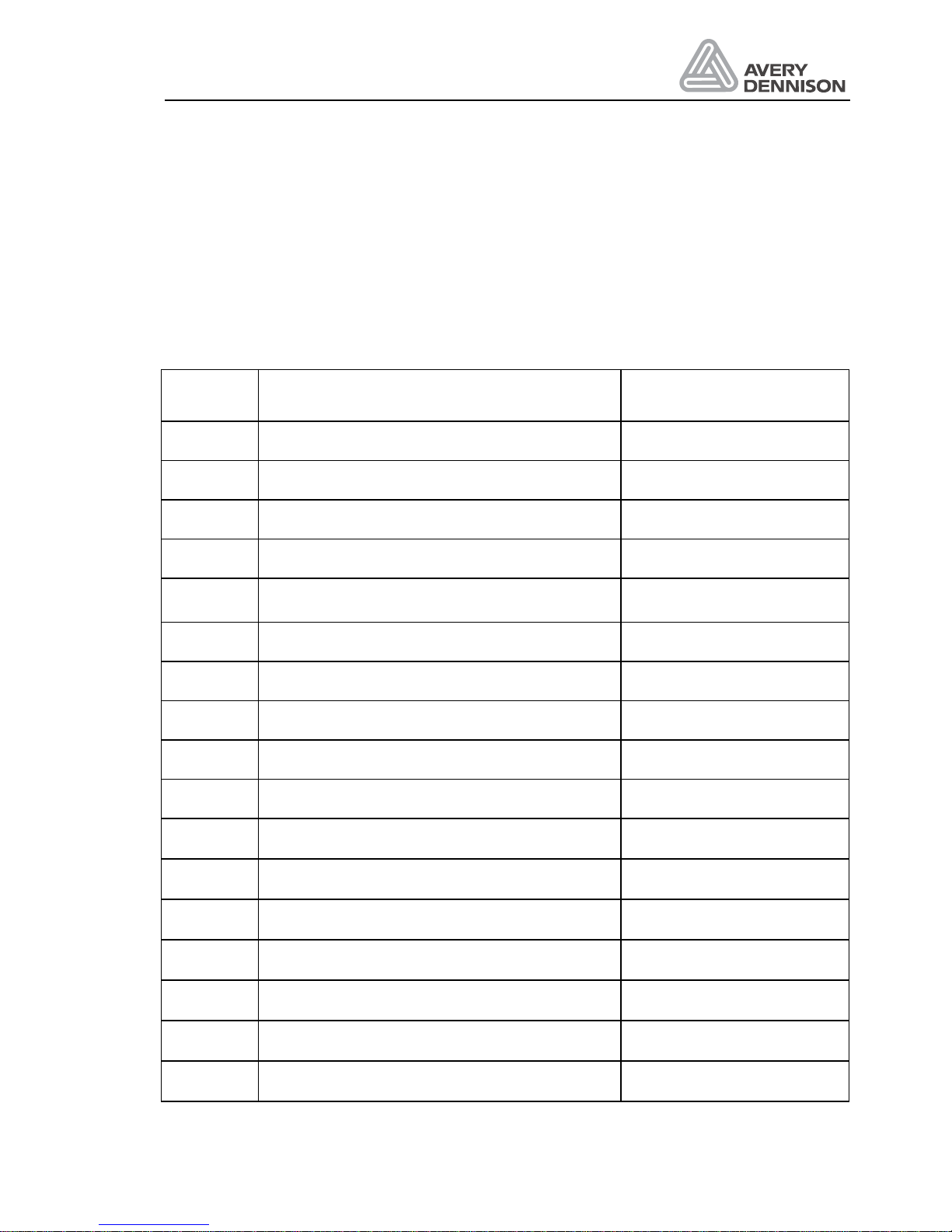
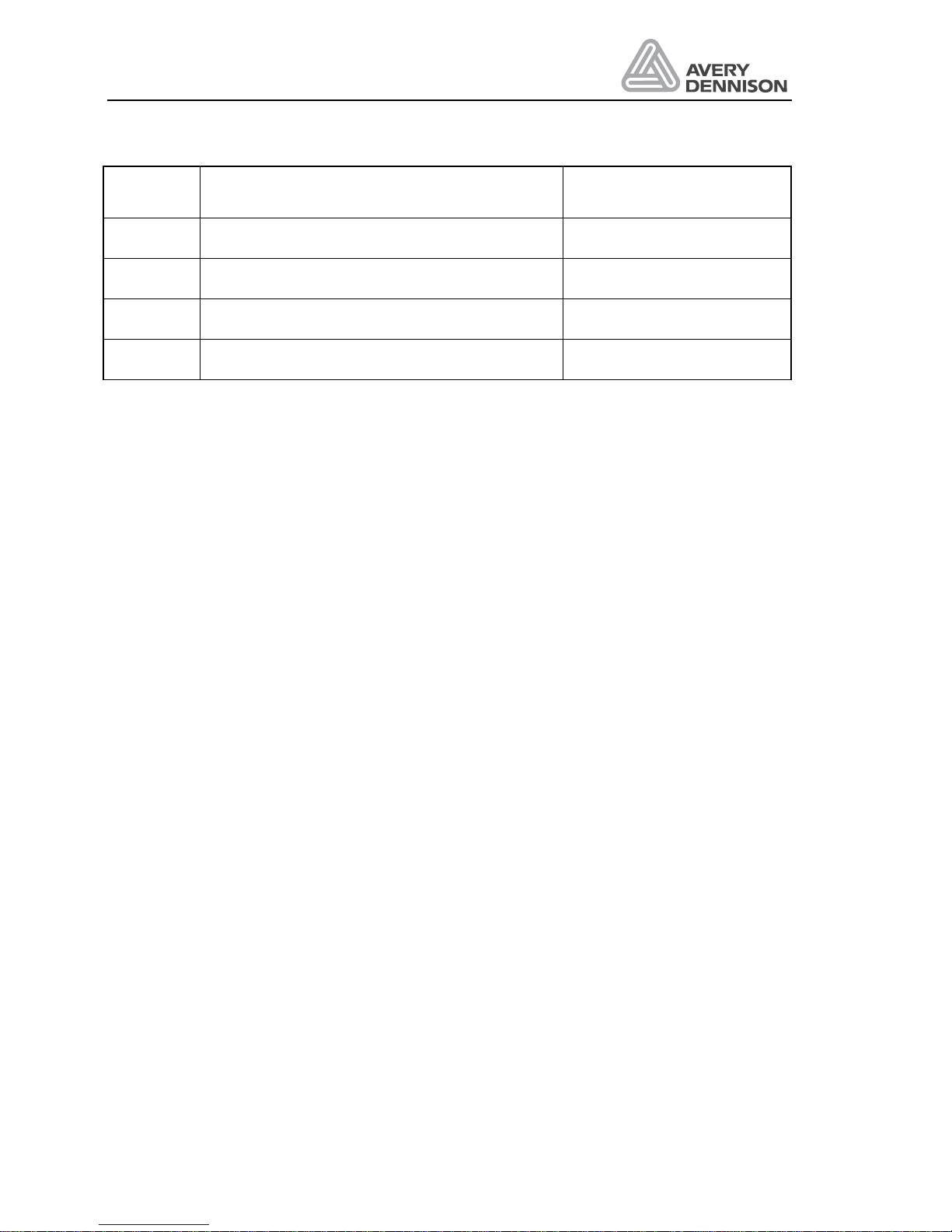
5.2 Extended standard menu
The extended standard menu offers additional parameters you may use in your application. On
quitting this menu the current parameter settings are stored in memory. Further changes are
also written into memory. As long as this menu is active, no labelling is possible. By pressing
the key FEED, however, single dispense of labels is possible.
To get into the extended standard menu a password CODE has to be entered. The display
shows the first menu point. A survey of all parameters is shown below.
Display Function Data value
LPIT Label pitch AUTO/5...999 mm
CONT Label sensor contrast value AUTO/1...200
SENS Sensor status LAB or GAP
STOD Stop position of label at the dispensing edge 0.0 .... 200.0 (mm)
PRDL Product length (inhibit of further product- sensor
signals)
AUTO, 5 ... 999 mm
POS Position of label on product Up to 999.9 mm
STAD Delay time for start of applicator cycle 1 ... 9999 ms
VELO Labelling speed 0.2 ... 30 m/min
STST Check adjusted EGRA value see text
SLEW Slew speed FAST or SLOW
EGRA Electronic gear ratio adjustment 100 to 500
APT1 Dwell time for applicator 1 ... 7500 ms
APT2 Blow on time for applicator 1 ... 7500 ms
APT3 Restart delay 0 ... 5000 ms
APT4 Time constant compensation 0 ... 500 ms
ASTP End of air stream signal -20 ... 50 mm
PDT Printer dwell time OFF - 1000ms
Page 44
Operators Manual
ALS 330/430
Release 8/07 Page 42 Menu structure
Display Function Data value
Printer hold time (is 50% PDT)
SAVE Store data in the product data bank PD01 ... PD09
LOAD Load data from a product data bank PD01 ... PD09
QUIT Leave the extended standard menu standard menu
Label pitch _______________________________________________________LPIT
Distance between 2 labels on the label web, measured from leading edge to leading edge. The
distance could be set manual or an automatic length measurement is also possible. In case of
automatic mode the length is measured with the INIT function. This should be normally done,
so label material could be easy changed. Only under special condition the manual mode has to
be used.
There are three different modes:
AUTO Select automatic measuring mode
A111 The automatic mode is on and a distance of 111 mm was measured
M111 The manual mode is selected and a length of 111 mm was entered.
Range: AUTO or 5 ... 999 mm.
Label contrast __________________________________________________ CONT
With this function the sensitivity of the standard label sensor could be adjusted. If AUTO is
adjusted, the machine scans automatically. The automatic modes doesn’t work with transparent
labels. In case of another type of sensor (mechanical or capacitive) the setting has to be
manual.
There are three different modes:
AUTO Select automatic measuring mode
A111 The automatic mode is on and a contrast of 111 was measured
M111 The manual mode is selected and a contrast of 111 was entered.
Range: AUTO or 1 ... 200.
Sensor status____________________________________________________SENS
Function: Status of label sensor is indicated, i.e. there is a label in the sensor the abbreviation
LAB is displayed and GAP is shown if there is only backing material inside the label sensor.
Can be used for all sensor types i.e. mechanical or electronic ones.
Page 45
Operators Manual
ALS 330/430
Release 8/07 Page 43 Menu structure
Stop position ___________________________________________________ STOD
Function: Stop position of the label at the dispensing edge.
Available: Always
Range: 0.0 .... 200.0 mm
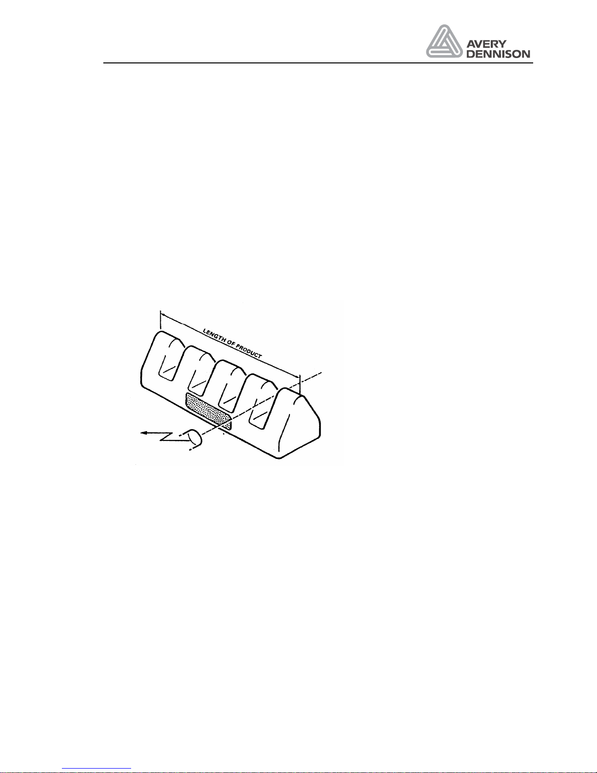
Product length ___________________________________________________PRDL
Function: The product length avoids multi labelling in case of difficult products. Normally it is set
to AUTO. This means that the product length is set to the label length.
After the product sensor has detected the edge of the product all signals that might be triggered
while the product is passing the product sensor are inhibited. This function can be helpful in
cases where the product is transparent or has several detection marks or edges. Such a case
is shown below.
The product sensor supplies several signals while the product passes the product sensor. If the
PRDL is not adjusted according to the dimension of the actual product the warning W_0 may
be given of false multiple product detection signals. The defined product length suppresses all
signals after the first product sensor signal has been received.
By pressing the keys FUNCTION the parameter PRDL is selected. The data input is selected
by pressing the key ENTER.
If an applicator is fitted to the labeller, the product length is not defined as a distance but as the
time that the product needs to pass the product sensor. The time is adjustable between 5 and
9999 ms.
Available: Always
Range: AUTO or 5 - 999 mm
Label position_____________________________________________________POS
Function: Position of label on the product.
Only available if no applicator is used.
Range: up to 999.9 mm in steps of 0.1 mm.
Page 46

Operators Manual
ALS 330/430
Release 8/07 Page 44 Menu structure
Start delay ______________________________________________________STAD
Function: Delay time for the dispensing by means of an applicator after the product has passed
the product sensor. This value influences the position of the label on the product.
Only available if applicator is used.
Range: 1 to 9999 ms
Dispensing speed ________________________________________________VELO
Function: The labelling speed may be adjusted with the parameter VELO. Values between 0.2
and 30.0 m/min are possible. The speed has to be adjusted so that it matches the product
speed.
When an applicator is fitted to the machine, this parameter defines how fast the label will be
dispensed on to the applicator.
EGRA value check________________________________________________ STST
Use this function to adjust the EGRA value. If the drive-roller speed is higher than that of the
conveyor then increase the EGRA value, if it is lower decrease the EGRA value so that the
conveyor speed and drive-roller speed match.
Slew speed _____________________________________________________ SLEW
Function: For some situations the labeller can run with a different, higher speed. This occurs
during compensation of a missing label on the web, positioning the label at the dispensing
edge during initialisation or after pressing the feed button if the APSF-mode is selected. The
resulting speed depends on the selection (FAST or SLOW) and the APSF-mode.
SLEW setting FAST SLOW
APSF off Max speed VELO
APSF on Max speed 12 m/min
Electronic gear ratio adjustment ___________________________________ EGRA
The parameter EGRA appears in the extended menu only after the APSF function has been
switched on.
The range of the EGRA parameter is 100 to 500, representing from 1 to 5 encoder pulses per
millimetre of conveyor movement. The full EGRA range can be used up to 30 m/min conveyor
speed.
With an applicator there is no realistic limit to the conveyor speed and at very high-speeds an
EGRA value at the lower end of the range should be used.
Dwell time_______________________________________________________ APT1
Function: Only used when an EP- applicator is necessary. It defines for how long the pneumatic
cylinder is switched on.
Available only with applicator.
Range: 1 ... 7500 ms
Page 47

Operators Manual
ALS 330/430
Release 8/07 Page 45 Menu structure
Blow on time_____________________________________________________ APT2
Function: Only used when an applicator is necessary. It defines for how long the label is blown
onto the product.
Available only with applicator.
Range: 1 ... 7500 ms
Restart delay ____________________________________________________ APT3
Function: This parameter defines the time for a next label dispense after the applicator cycling
is completed.
Available only with applicator.
Range: 0 ... 5000 ms
Time constant compensation_______________________________________ APT4
Used to control the labelling position when using an applicator in conjunction with APSF.
The parameter APT4 is set to the time that the label takes to reach the product from the start of
the applicator cycle. For blow applicators this will probably be less than 25 ms, for EP (aircylinder) applicators the time will be much more - possible 60 ms to 100 ms depending on the
length of the air cylinder.
To calculate the correct value proceed as follows:
Set APT4 to 1. Run the conveyor at a fairly low speed such as 10 m/min and note the label
position on the product. Now run the conveyor at a much higher speed such as 25 m/min and
note how far the label position has shifted back.
Use the following formula to calculate the correct value for APT4...
(LABEL SHIFT (mm) x 60) / (Vhigh - Vlow) = APT4
Vhigh represents the higher conveyor speed used (in m/min)
Vlow represents the lower conveyor speed used (in m/min)
eg. If the shift is 3mm and the conveyor speeds 10 m/min and 25 m/min are used the correct
value for APT4 is:
(3 x 60) / (25 - 10) = 180 / 15 = 12
The calculated value should then be tested by running the conveyor at a high and a low speed
and checking that the placement position does not change. If the label position moves back
slightly at higher speed then increase APT4 a little, if it moves forward at higher speed then
decrease APT4 a little.
Note: The EGRA parameter must be set correctly as well as the APT4 parameter
for correct label positioning on the product.
Page 48

Operators Manual
ALS 330/430
Release 8/07 Page 46 Menu structure
End of air stream signal ___________________________________________ASTP
This parameter determines how long the air stream signal will remain active after the label
dispense has finished. Valid in all modes (direct dispense, applicator, APSF and fixed-speed).
Printer dwell time__________________________________________________ PDT
This determines the dwell time of the stamp-printer. A new dispense is prevented after PDT
expires for a time equal to 50% of PDT.
Save parameter in data bank _______________________________________SAVE
Function: After selection this function you can save the current parameter setting to a data
bank.
Always available.
Range: NEW1 .. NE15 Create a new data bank
PD01 ... PD15 Overwrite existing data bank
EXIT Leave function without modification
Load data bank _________________________________________________ LOAD
Function: After selection this function you may load a predefined parameter setting.
Always available.
Range: PD01 ... PD15 Load a defined data bank
EXIT Leave function without modification
Leave Menu finishing _____________________________________________ QUIT
Function: If this function is selected, you get back to the standard menu
Always available.
Note: Modified parameter values are only stored if the menu is left by using the
QUIT function. If the power is switched off before leaving the menu by quit all
modifications are lost.
Page 49

Operators Manual
ALS 330/430
Release 8/07 Page 47 Menu structure
5.3 Product menu
If parameters have to be changed because of different products and labels, the product menu
can be used. The machine offers a data bank in which 14 sets of data can be stored.
If you want to switch to a particular product, select one of the product numbers by pressing
NEXT or PRIOR and confirm with ENTER .The new parameters are valid now.
After switching to a new product bank the machine assumes the label roll has been changed or
that a parameter such as STOD is different and so requires an initialisation of the label position
at the dispensing edge. This is done by pressing the FEED key after loading a new product
bank at which time the machine will move the first detected label edge to the dispense position.
Note: If the FEED key is not pressed after loading a new product bank the first
detected label edge will be moved to the dispense position at the first signal from
the product sensor!
Note: The function FACT available in the configuration menu clears all the product
banks.
Page 50

Page 51

Operators Manual
ALS 330/430
Release 8/07 Page 43 Configuration menu
6. Configuration menu
Adjustments in the configuration menu are necessary during installation of the machine only. In
the configuration menu, the required optional functions can be selected. Some service
support functions in the configuration menu will be useful for the service staff.
Possible adjustments:
y
Recognition of the product at the leading or trailing edge
y
Left or right hand version of labeller
y
Machine type
y
direct dispensing or several type of applicators
y
Parameters for the interface
Possible tests:
y
In/output test
y
Test run without labelling
The function Factory initialisation resets all parameters to default values.
Calling the configuration menu
There are two ways to call the configuration menu:
y
Press the key ENTER and switching on power at the same time. The display shows
'CODE'.
y
Press the keys NEXT and PRIOR at the same time when a parameter function is displayed.
The display shows 'CODE'.
The password has to be entered by pressing the following keys:
* 1 time PRIOR FUNCTION
* 3 times NEXT FUNCTION
* 2 time ENTER
* 3 times NEXT FUNCTION
When the password is entered correctly, the display shows `DTST`. After pressing PRIOR or
NEXT the next menu, point will be shown. If a wrong password was entered, you go back to the
previous menu.
Page 52

Operators Manual
ALS 330/430
Release 8/07 Page 44 Configuration menu
6.1 Handling the menu
The menu structure is shown in the following table. By means of the key PRIOR you switch to
the prior function, and with the key NEXT to the next following function in the menu.
If you press the key ENTER the current parameter value of a function is shown. The current
parameter value can be changed with the keys PRIOR FUNCTION or NEXT FUNCTION.
Values are stored by pressing the key ENTER.
Display Function of the parameter Possible data entry
DTST Test run without labels
P_S_ Product sensor detects at leading or
trailing edge of product
LEDG, TEDG
MACH Machine type 230, 720, 330, 430
MDIR Motor running direction for left or right
hand
<---- --->
MLAB Handling of missing label NONE, WARN, ERR1, ERR2,
ERR3
APSF Automatic product speed follower YES, NO
APPL Direct dispense mode, or applicators DIR, ASA, EP, RVEP
I_CH Test of inputs
O_CH Test of outputs
FACT Reset of all parameters to default values YES, NO
BAUD Baudrate of the interface NONE, 300 to 192%
PARI Parity bit NO, 0PRT, ODD, EVEN
SBIT Number of Stop bits 1 bit, 2 bit
DBIT Number of data bits 7 bit, 8 bit
RECY Recycle (simulates max labels/min) see text
DIST Distance label sensor to dispensing edge 10 ... 999 mm
LABC Number of dispensed labels see text
QUIT Return to extended standard menu
Page 53

Operators Manual
ALS 330/430
Release 8/07 Page 45 Configuration menu
6.2 Menu functions
The menu functions are explained in detail here.
Permanent test___________________________________________________DTST
The permanent test makes a test run without using labels. In the display the numbers of
dispense cycles is shown (see description LABC). Immediately after starting the function, the
machine runs in a self-test. The test run works with all adjusted parameters. The test can be
stopped by pressing the key ENTER.
Polarity of the product sensor ______________________________________ P_S_
The machine requires a start signal for each product to be labelled. After the start delay (STAD)
the labelling starts. The signal is usually created by a light sensor at the conveyor. A PLC can
also supply this signal. The light sensor supplies a signal when the light beam is interrupted by
the product. By means of the function P_S_ it will be selected whether the leading edge or the
trailing edge of the product should trigger the signal.
Usually the trailing edge of a product is used. Reasons for detecting the leading edge can be:
- shape of product (your should avoid detecting a radius or a declined edge)
In case of using other than the standard product sensor’s, the meaning of the display can be
reversed. The adjustment you need you may change with the keys NEXT or PRIOR.
Factory adjustment: LEDG
Machine type ___________________________________________________ MACH
The software is identical for several different machines. Choice the correct type.
Factory setting: The last setting remains after a factory reset.
Dispensing direction ______________________________________________ MDIR
The machine is available in a right and left-hand version. In the right hand version the product
transport is from left to right when you look to the front of the machine. The adjustment is done
in the factory and should not be changed.
Factory setting: The last setting remains after a factory reset.
Handling of missing label _________________________________________ MLAB
There are several condition the dispenser is not able to dispense a product:
y
the distance between products is too close
y
an additional printer is not fast enough
y
the loop in the ALX720 is empty (end of job, printer error)
Page 54
Operators Manual
ALS 330/430
Release 8/07 Page 46 Configuration menu
With this function, you can decide how to react:
NONE Do nothing. The unlabeled product will be detected later in the line.
WARN Set the warning output and displays W__0. The production continued.
ERR1 Set the error output to stop the production line immediately and display E_10.
ERR2 The first unlabeled product generates the warning. Two unlabeled products in a
sequence set the error.
ERR3 The error condition will be set at 3 unlabeled products.
Automatic product speed follower
_________________________APSF
Under parameter APSF the automatic product speed follower function can be activated (ON /
OFF). The APSF sensor is fitted to the conveyor and supplies signals that represent the speed
of the conveyor. The installation of the sensor and the adjustment of the parameter have been
carried out according to your application and should not be changed.
The compensation steps for the current conveyor speed are constantly recalculated rather than
just when the product-sensor is triggered. This means that a change in conveyor speed
between the time that the product is detected and the time it reached the dispense position has
no effect on labelling placement accuracy.
There is no optimum EGRA setting. The compensation steps are calculated using the current
EGRA setting rather than using fixed compensation step values for a predetermined EGRA
setting and so any EGRA value works just as well.
At slow speeds the label dispense speed matches the conveyor speed exactly regardless of the
EGRA setting. For instance if the dispenser needs to make 1.236 steps per encoder pulse then
at the first four encoder pulses the dispenser will make one step but will then have fallen
4x0.236=0.944 steps behind. On the fifth encoder pulse the dispenser will make two steps and
so be (5x0.236)-1=0.18 steps behind. The dispenser will always be less than one step behind.
The dispenser thus always dispenses the correct amount of label in regard to the product
movement even when the conveyor is starting from rest or coming to rest.
Type of applicator ________________________________________________APPL
In most cases, the label is dispensed directly onto the product. If this is not possible, an
applicator has to be used. We offer a number of different applicators. In this function, the
installed applicator has to be defined. You may select the applicator type you have ordered for
your application (display shows 'ASA`,`EP`, RVEP or another applicator). In case of direct
dispensing the function direct dispense has to be chosen:
Display shows 'DIR'.
The adjustment is done in the factory and should not be changed.
RVEP (ReVerse EP) operates as an EP applicator except that once the label has been
dispensed onto the applicator the applicator cylinder is extended to wait for the next product to
arrive. This provides more accurate labelling than with EP applicators because variation in the
time it takes for the cylinder to extend does not affect the labelling position.
Page 55

Operators Manual
ALS 330/430
Release 8/07 Page 47 Configuration menu
Additional functions in the standard menu
Depending on which parameter has been defined under APPL different menu functions are
shown in the standard menu. If an applicator is used additional times BLOW and STAD for
controlling the applicator cycling are available.
Input and sensor check____________________________________________ I_CH
To display the status of sensor’s and inputs information are grouped in 3 blocks you can select
by pressing the NEXT or PRIOR keys. The character for the inactive state is different to identify
the various blocks.
Block 1 (inactive = 0)
N = Power fail detection (only can case of malfunction)
P = Product sensor active
A = Signal from APSF sensor
R = Ready input stepper motor control
Block 2 (inactive = -)
I = Inhibit input active
L = Unused input (Loop control on ALX 720)
H = Applicator home switch active
E = Applicator end switch active
Z = Horizontal home switch
Block 3 (inactive = .)
S = pressure switch activated
J = Jumper 3 closed
O = OD control material active
M = Label sensor on material
G = Label sensor on gap
For a correct label sensor information CONT has to be adjusted before. Leave the function by
pressing key ENTER.
Output check ___________________________________________________ O_CH
With the NEXT and PRIOR keys you can select the output you will switch on for testing. Leave
the function by pressing key ENTER.
On selecting the O_CH function the display shows "1" and the first output is active. Using the
up-arrow and down-arrow keys the user can select any one of outputs 1 to 8. Only one output
is on at a time so that the user can easily see if he has any shorted connections (any output
that is being turned on by another part of the program such as an error or ODC output will stay
on until the error or ODC input is cleared).
1 = terminal 15 = BLOWON
2 = terminal 16 = AIRSTREAM
3 = terminal 17 = CYLINDER
4 = terminal 18 = PRINT_OUT
5 = terminal 19 = WARNING
6 = terminal 20 = ERROR
Page 56

Operators Manual
ALS 330/430
Release 8/07 Page 48 Configuration menu
7 = terminal 31 = READY
8 = terminal 32 = ODC_OUT / HORI_CYL
Adjustment resetting______________________________________________FACT
This menu point sets all parameters back to the factory values. All parameters will be reset, so
please note all your adjustments before. When you call this function the display shows 'NO`.
After you have left by pressing the key ENTER there is no change.
When you change with the key NEXT to YES and press ENTER all parameters are reset to
default values.
Note: This function also clears all product banks.
Interface baud rate_______________________________________________ BAUD
With this function the baud rate of the interface will be adjusted. This is an option of the
machine. If you do not have this option, the parameter has to be set to 'NONE` to protect the
interface and to avoid errors. The following baud rates are adjustable: 150, 300, 600, 2400,
4800, 9600 and 19200 baud. When calling the function FACT this parameter will be set to
`NONE`. When the machine is delivered with the interface the baud rate is set to 9600. Select
your baud rate by pressing the key NEXT or PRIOR . With the key ENTER the adjustment is
stored.
Factory adjustment: NONE
Parity bit ________________________________________________________ PARI
The function is only visible if a baudrate is selected. The parity bit is necessary to check the
data transfer. In case of wrong data transfer an error message will be given. The adjustment of
both machines has to be identical. Usually the transfer is made without parity bit.
Possible adjustments:
'NO`: Not sending or receiving a parity bit
`EVEN`: produce a parity bit so that an equal number of `1` signals is created
`ODD`: produce a parity bit so that an odd number of '1' signals is created.
`0PRT`: The parity bit is always 0
By pressing the key NEXT or PRIOR the adjustment is selected and by pressing the key
ENTER the function is finished.
Factory adjustment: NO
Number of stop bits_______________________________________________ SBIT
The function is only visible if a baudrate is selected. This parameter defines the number of stop
bits. By pressing the key function you can select between `1BIT` or `2BIT`. By pressing the key
ENTER this function will be left.
Factory adjustment: 1BIT
Page 57

Operators Manual
ALS 330/430
Release 8/07 Page 49 Configuration menu
Number of data bits_______________________________________________ DBIT
The function is only visible if a baudrate is selected. With this function you can select between 7
or 8 data bit protocols.
Factory adjustment: 8BIT
Recycle (simulates max labels/min) ________________________________ RECY
The Auto-recycle function, is used to determine the maximum possible cycle rate with the
current parameter settings.
It will cycle through applicator cycles automatically by internally generating a product-start the
instant a cycle has been completed and displays the average cycle rate per minute in the
display. It also operates with no applicator selected by dispensing labels at the maximum
possible rate. The maximum labelling rate for different values of PDT can be determined using
the RECY function without having to physically connect the printer.
Distance sensor to dispensing edge _________________________________ DIST
This function defines the distance between the material label sensor and the dispensing edge.
This value is shown in steps of 0.1 mm (e.g. 0456 means 45.6 mm). The measured value can
be adjusted by pressing the key FUNCTION.
If the DIST value has been adjusted correctly the first leading label edge detected at
initialisation will be moved exactly to the dispensing edge, as long as STOD is set to 0.0 (mm).
This parameter is important for the missing label compensation. If it is not correctly adjusted a
missing label on the material roll, will not be compensated correctly and the product will not be
labelled.
Value range: 10.0 .... 999.9 mm
Label counter ___________________________________________________ LABC
Each dispensed label increases the counter by 1. The capacity of the counter is for
999 999 999. The total number can be seen in 3 sections, press the keys FUNCTION as
described down below:
Mnnn Knnn .nnn
y
where M represents millions
y
K represents thousands
y
.represents units
On entering the "LABC" parameter the units are displayed. By using the arrow keys can then
be used to change between the millions, thousands and units displays.
By pressing NEXT and PRIOR at the same time the counter is set to 0. By pressing the key
ENTER the function will be left.
Leave Menu finishing _____________________________________________ QUIT
Function: If this function is selected, you get back to the standard menu
Page 58

Operators Manual
ALS 330/430
Release 8/07 Page 50 Configuration menu
Note: Modified parameter values are only stored if the menu is left by using the
QUIT function. If the power is switched off before leaving the menu by quit all
modifications are lost.
Page 59
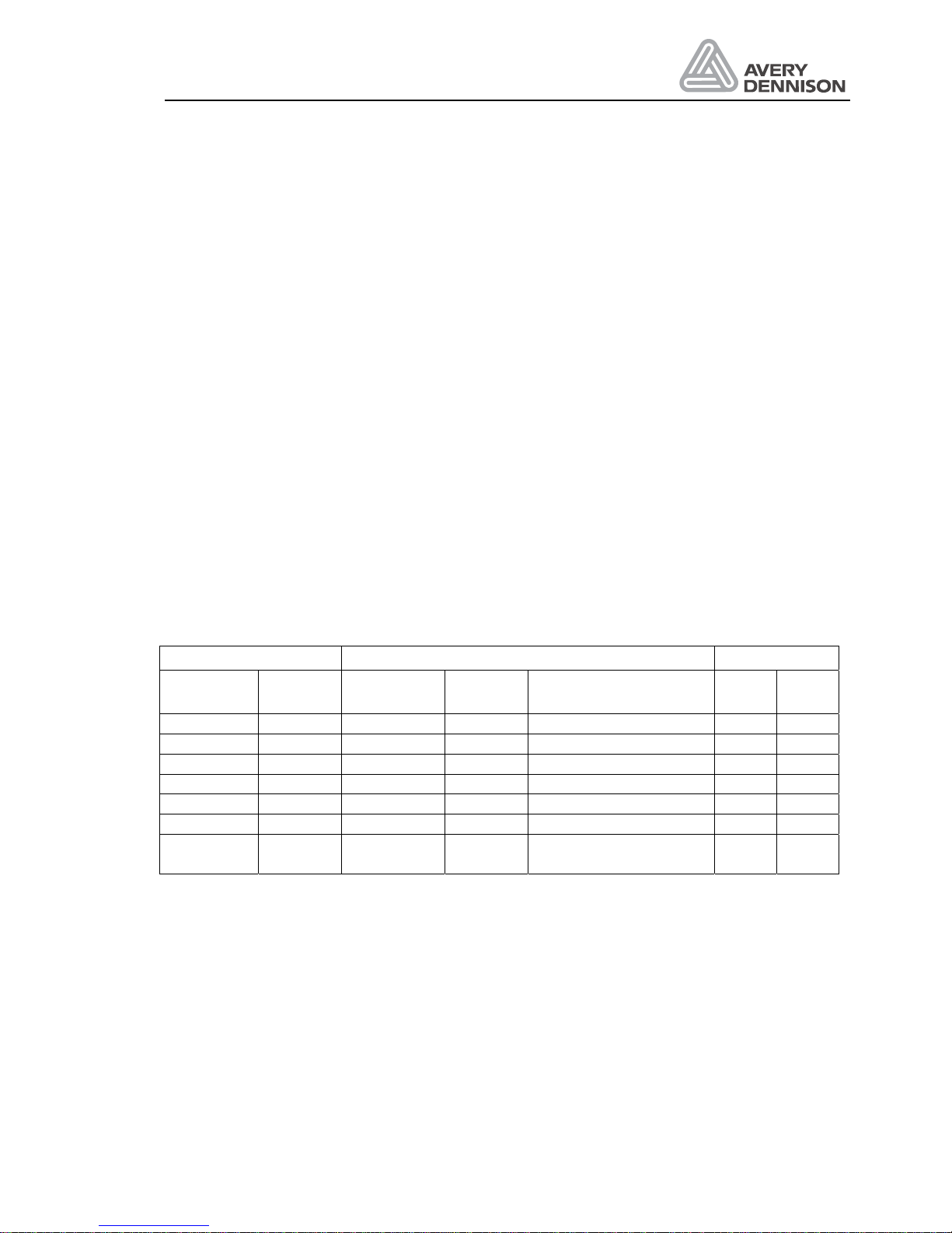
Operators Manual
ALS 330/430
Release 8/07 Page 51 Serial interface
7. Serial interface
The machine has a serial interface according to the standard RS232C. Via this interface
parameters can be adjusted. All received commands are tested for syntax and legal value
range.
Invalid commands and parameters are ignored. An error message is not given in this case.
All commands received over the serial interface are tested for syntax and range; invalid
commands and out of range parameter values are ignored. A warning message is not given in
these cases. However in the case of framing, parity or overrun errors the warning "W__3" is
generated.
The commands are made up of sequences of ASCII characters. Each command starts with "#"
and "!" followed by a 4 character code. The reception of the "#" character indicates the start of
a new command to the machine.
The codes are similar to the parameter names shown in the display.
7.1 Data of the serial interface
The pin connection of the interface plug is shown in the table below.
Dispenser connector Signal description PC
25 pol DSub
9 pol DSub
Direction Code Description 25 pol 9 pol
Socket 2 3 Output TxD Transmit data 3 2
Socket 3 2 Input RxD Receive data 2 3
Socket 5 8 Input CTS Clear to send 4 7
Socket 4 7 Output RTS Request to send 5 8
Socket 7 5 GND 7 5
Socket 20 4 Output DTR 6 6
Socket 24 (if jumper
on)
+ 10V For external use 8
All other pins are not connected.
Adjustable data values
Baudrate 150, 300, 600, 1200, 2400, 4800, 9600, 19200 Baud
Data bits 7 or 8 bits
Stop bits 1 or 2 bits
Parity No Parity, Parity bit always 0, odd or even parity
Handshake RTS/CTS
Factory interface deactivated, at reactivation the parameters will be set to 8 data bits, 2
stop bits and no parity bit.
Page 60

Operators Manual
ALS 330/430
Release 8/07 Page 52 Serial interface
7.2 Interface commands
The below described commands will change one of the labelling parameter. The values are not
stored and will be lost when turning off power.
If the sequence nnnn is replaced by the character "?" then the current value of that parameter
will be returned by the labelling machine as a 4 character string confirming the name of the
parameter requested followed by 4 numbers representing the current value of that parameter.
The character 04H terminates all return messages.
Example
PC send the message: #!VELO?
Machine returns: VELO0300<04H>
Command Description Range
#!APOSnnnn Value APOS
-0050 – 0100 mm
#!APPLnnnn Applicator type 0000 direct dispense
0001 ASA
0002 EP
0003 EP_U
0004 PLUA
0005 INDX
#!APSFnnnn APSF function 0000 off
0001 on
#!APT1nnnn Applicator time
0001 – 7500 ms
#!APT2nnnn Applicator time
0001 – 7500 ms
#!APT3nnnn Applicator time
0000 – 5000 ms
#!ASTPnnnn Value ASTP
-0020 – 0050 mm
#!BANKnnnn Change product bank
0000 - 0009
#!BLOWnnnn Blow on time = APT 2
0001 - 7500 ms
#!COMPnnnn Automatic label compensation 0000 = Off
0001 = On
#!CONTnnnn Material contrast 0001 – 0200
0000 automatically
#!DISTnnnn Distance label sensor – dispensing
edge
0080 – 9999 * 0.1 mm
#!EGRAnnn Gear ratio
0300 – 1000
#!LPITnnnn Label length 0005 – 0999 mm
0000 automatically
#!MACHnnnn Machine type 0000 ALS230
0001 ALX720
0002 ALS330
0003 ALS430
#!MDIRnnnn Motor direction 0000 Right --- >
Page 61

Operators Manual
ALS 330/430
Release 8/07 Page 53 Serial interface
Command Description Range
0001 Left < ---
#!MLABnnnn Missing label error 0000 NONE
0001 Warning
0002 Error 1
0003 Error 2
#!PDT nnnn Print dwell time 0001 – 1000 ms
0000 printer off
#!PHT nnnn Printer hold time
0001 – 7500 ms
#!POS_nnn Labelling position
0001 – 9999 * 0.1 mm
#!PRDLnnnn Product length
0005 – 4000 mm
#!P_S_nnnn Polarity product sensor 0000 LEDG
0001 TEDG
#!RAMPnnnn Acceleration Ramp 0000 NORM
0001 FAST
#!SLEWnnnn Slew speed 0000 = FAST
0001 = SLOW
#!STADnnnn Start delay
0001 - 9999 ms
#!STODnnnn Stop position
0080 - 9999 * 0.1 mm
#!VELOnnnn Speed
0020 - 0300 * 0.1m/min
#!SAVEnnnn Store in data bank
0001 - 0009
#!LOADnnnn Load data bank
0001 - 0009
The following described commands do not have parameter values. With these commands the
host can monitor and control the machine.
#!CLRC Set label counter to 0
#!CLRE Clear error message
#!CLRW Clear warning
#!ERRF The machine sends an error status to the monitoring computer. The message
ERR8___4__1_<04H> means, error 8, 4 and 1 have occurred.
#!WARF The machine sends a warning status to the monitoring computer. The message
WARF7______0 means: The warnings 7 and 0 have occurred.
#!LABC The machine sends the number of dispensed labels e.g. LABC0000008359 back
#!SP__ The machine is set to off. The product sensor is disabled and labelling will
therefore be stopped.
Page 62

Operators Manual
ALS 330/430
Release 8/07 Page 54 Serial interface
#!SR__ The machine is set to on. The product sensor is enabled and labelling can
restart.
For a full automatic operation, the following procedure in case of an error is required:
y
#!ERRF Request error
y
#!CLRE Clear error message after fixing the error. The labeller shows „INIT“
y
#!SR__ Clear INIT message
Bit definition in error flag
Error number Error message in display Error description
0 E__0 Pressure roller open
1 E__1 End of material (4 missing labels)
2 E__2 EP-applicator error
3 E__3 checksum error configuration data
4 E__4 checksum error parameter bank
5 E__5 Error 10V low
6 E__6 Error 24V low
7 E__7 missing label on product
8 E__8 Error motor driver
Bit definition in warning flag
Warning Message in display Warning description
0 W__0 Next product start before finished
1 W__1 Product start but no material not initialised
2 W__2 EEPROM error during write
3 W__3 Interface warning
4 W__4 APSF speed too fast
5 W__5 End of material (OD-Control)
6 W__6 too many products
7 W__7 Loop not ready (720)
Page 63

Operators Manual
ALS 330/430
Release 8/07 Page 55 Connections and signals
8. Connections and signals
This machine has a number of inputs to connect sensor’s and a control. Outputs are available
for applicators, a printer and other purposes.
8.1 Output signals
This machine has eight outputs, which switch the output from open circuit to + 24V. The
maximum current must not exceed 500 mA. The four signals for error messages, machine
ready, low material and warnings are available for other machines in the process or additional
alarm signals. For connecting an applicator three signals are available and one additional for
the printer.
The output signals are available at terminal connector CN33 on the main board. The wiring of
the terminal is shown otherwise.
8.1.1 Error and warning output
The outputs for errors and warnings are available on the terminal CN33 and optional on the I/O
plug. The signals are switched active (+24V) if an error or warning occurs. When the error or
warning is erased, the signal becomes passive again.
8.1.2 Printer output
This machine can be connected to a printer. To use the printer the PDT parameter should be
adjusted.
A new label cannot be dispensed until the printer dwell time set in PDT is over.
8.1.3 OD-Control output
This output is switched active (+24V) if the OD-Control input is switched active during
dispensing.
8.1.4 Ready output
This output shows when the machine is ready for labelling. This output is switched inactive if
there is:
• an error message appears in the display
• the mains supply voltage has fallen below specification
• the machine requires initialisation
• in OFF condition.
Page 64

Operators Manual
ALS 330/430
Release 8/07 Page 56 Connections and signals
8.2 Applicator modes
The machine is able to dispense the label direct on the passing product. There is also the
possibility to drive without any external control a wide range of applicators.
8.2.1 Signals for direct dispense
For direct dispensing the airstream signal can be used to control a pneumatic driven dispensing
edge. The start of the airstream signal (= motor run signal) could be behind the start of the
dispense motor, adjusted with the function APT3. The signal is switched inactive, when the
label dispense has been completed. Also the stop could be adjusted with the function ASTP to
switch inactive before or behind the dispense motor stop.
Ready
Product start
Label start
Suppression
Product start
Suppression
Dispense
Motor run
signal
1
2
3
4
POS
POS
POS
PRDL
APT3
ASTP
ASTP
1
Productstart disabled. PRDL activ
2
Missing Label: New start of dispense during dispenser activ
3
Inhibit activ
4
Machine not ready. Errorcondition or not online
Figure 17 Timing diagram direct dispense
Page 65
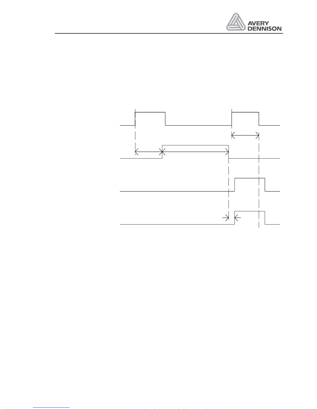
Operators Manual
ALS 330/430
Release 8/07 Page 57 Connections and signals
8.2.2 Control signals for the ASA applicator
For controlling an air stream applicator the signals air- stream and blow on are necessary. The
time period APT2 defines how long the blow on signal is active. After labelling the product and
the time period of APT3 a new label will be dispensed on to the applicator. After that the
machine is ready for a new labelling.
All errors are given after 5 seconds!
Productstart
Airstream va lve
STA D
Blowon va lve
APT3
APT2
1
1 Missing Label: Labeller not ready for dispense
STA D
Dispense label
Figure 18 Timing ASA applicator
Page 66
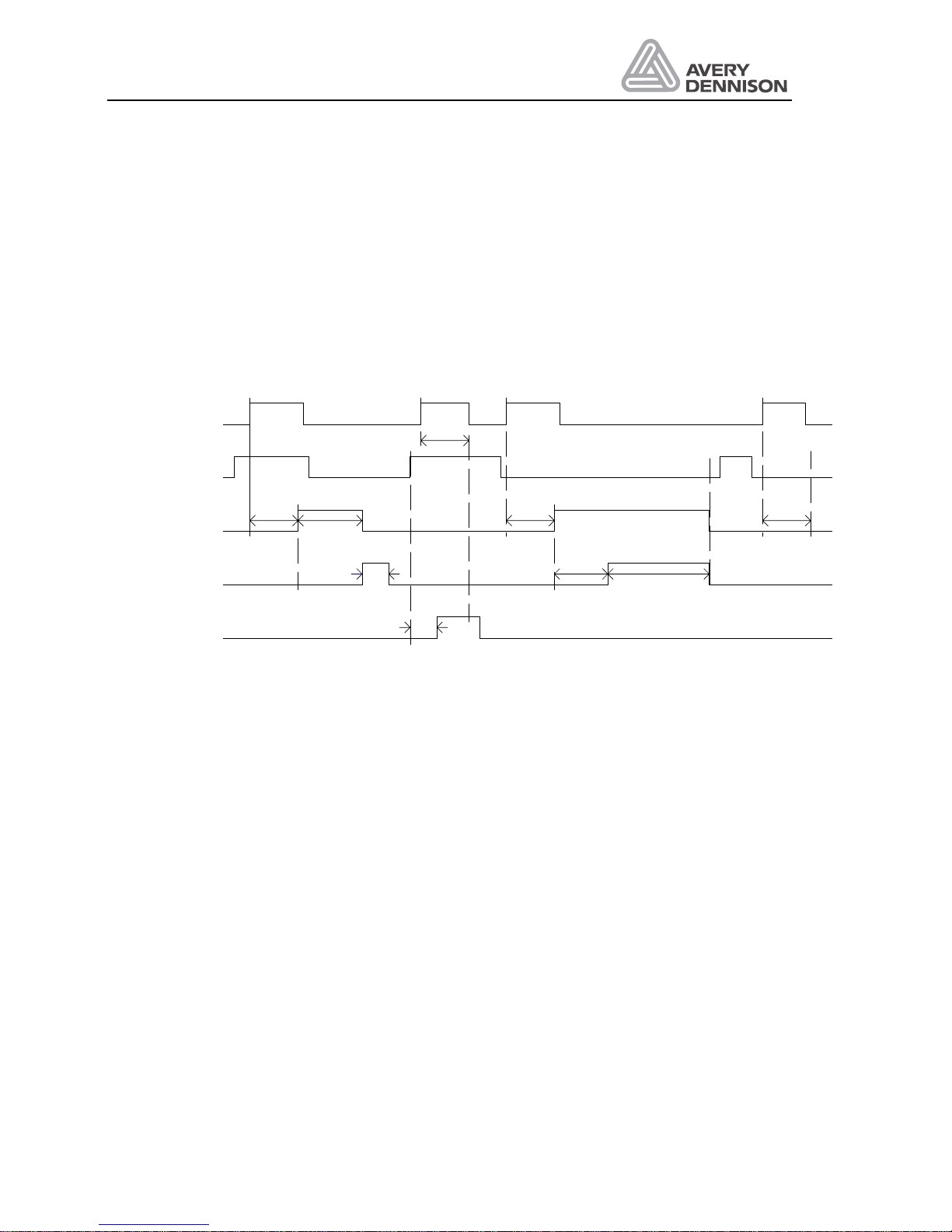
Operators Manual
ALS 330/430
Release 8/07 Page 58 Connections and signals
8.2.3 Signals for the EP applicator
For controlling the applicator the signals air stream, cylinder valve and blow on are necessary.
After a product signal has occurred the labelling cylinder valve is switched active after the delay
STAD. However if at this time the applicator is not in the home position then error message
E__2 is generated. After the delay time APT1 the blow on valve is switched active for the time
APT2.
When APT2 is completed both the labelling cylinder valve and the blow on valve signals are
switched inactive. If the control does not read the home position in the time given - 3* (APT1+
APT2) - than the error message E__2 is generated.
Productstart
Cylinder valve
Dispense label
+ Airstream valve
Blowon valve
Homeswitch
12Missing Label: Labeller not ready for dispense
Error: Applicator not in homeposition3
Error: Homeposition not detected
STAD AP T 1
APT3
APT2
1
3
STAD
STAD
APT1 4 * (APT 1 + APT 2)
STAD
2
Figure 19 Timing EP applicator
Page 67
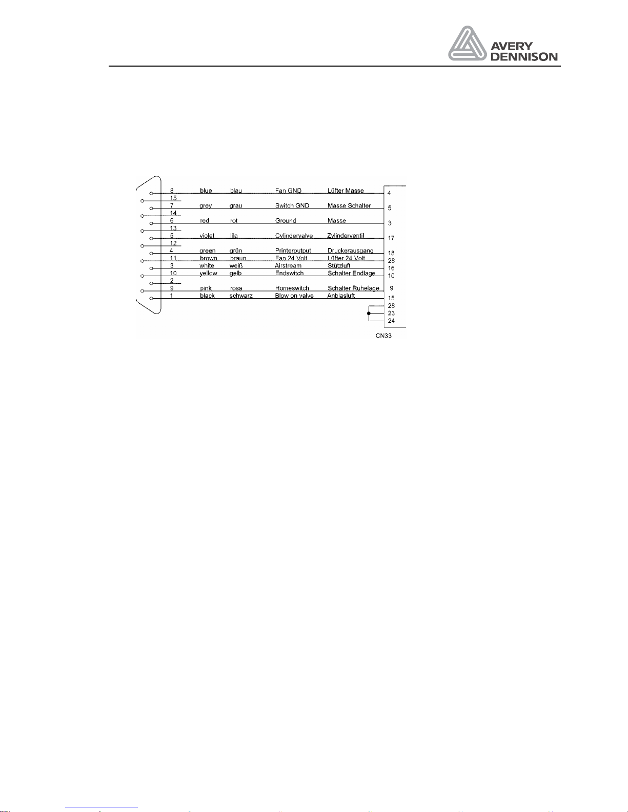
Operators Manual
ALS 330/430
Release 8/07 Page 59 Connections and signals
8.2.4 Applicator connector
The applicator connection is done via a 15 pole D-sub connector common to other machines.
Figure 20 Applicator connector
Page 68
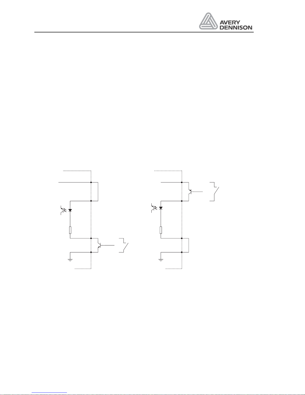
Operators Manual
ALS 330/430
Release 8/07 Page 60 Connections and signals
8.3 Input signals
This machine (dispenser) is provided with photo coupled inputs for:
y
the product sensor signal
y
an inhibit signal for inhibiting labelling
y
a signal from an OD control which shows the end of the material roll.
y
a signal from an automatic product speed follower
y
the EP applicator signals from the HOME and END switches
y
an unused input for future extensions or customer specific software (used for loop control in
the 720)
The inputs are galvanically separated through photo couplers to connect to PNP or NPN
outputs. The wiring and the connection of the signal plug is shown otherwise. The input voltage
across the inputs must be in the range of 15 V to 30 V to switch active.
ln+
Signal
ln-
Machine
(alternative switch)
+24V DC
NPN
Optoisolator
2K2
ln+
Signal
ln-
Machine
(alternative switch)
+24V DC
PNP
Optoisolator
2K2
Figure 21: Connectin g NPN (left) or PNP (right) inputs.
Page 69
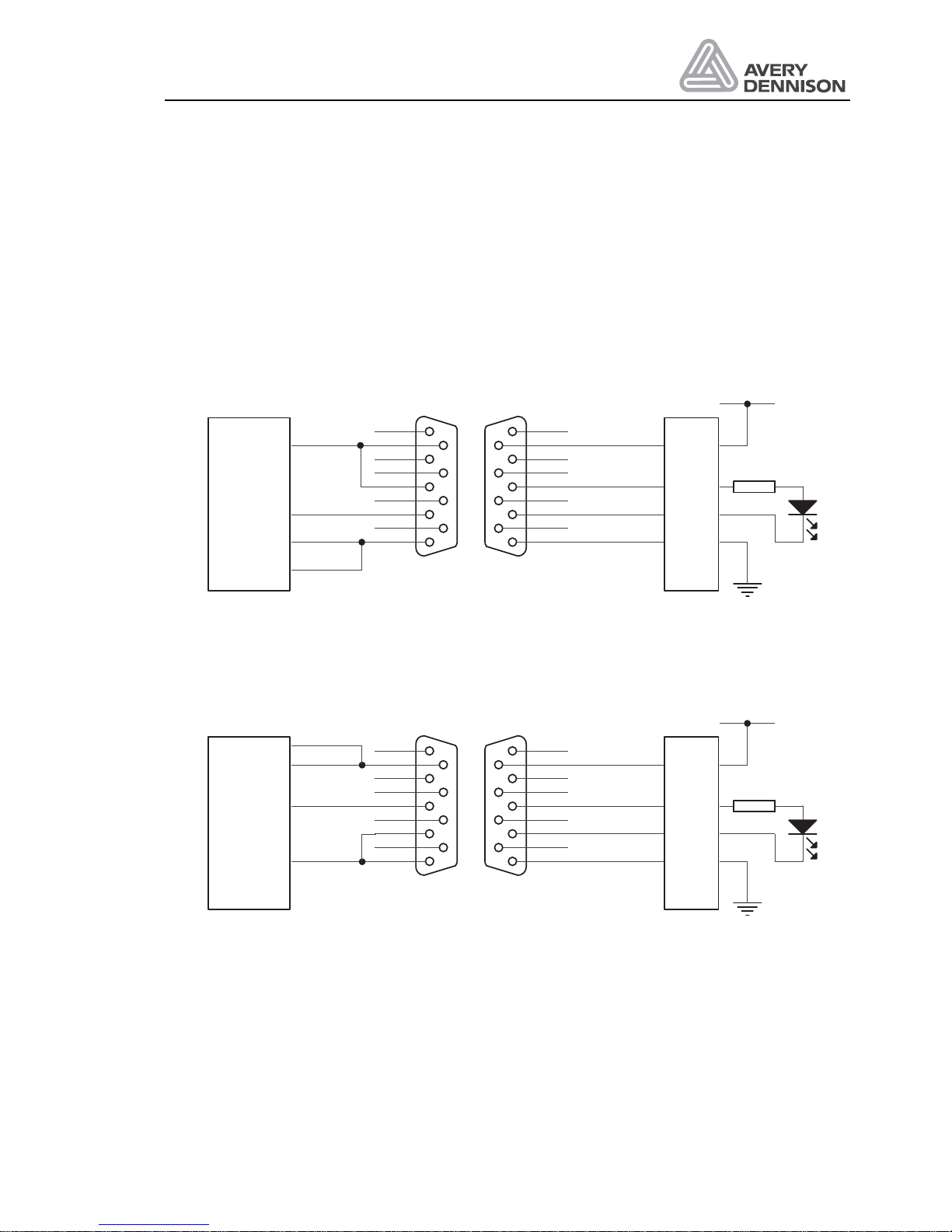
Operators Manual
ALS 330/430
Release 8/07 Page 61 Connections and signals
8.3.1 Product sensor
The product sensor starts the labelling. The source of the signal could be a optical sensor, a
switch or a signal from a PLC. The time between start signal and start of dispensing (adjusted
with POS) should be as small as possible. This means that an optical sensor should be placed
10 to 20 mm before the dispensing edge. The minimum distance is necessary for the internal
speed compensation.
The machine is supplied as standard with one socket for connecting the product sensor. You
may either use a NPN or PNP type sensor output.
+24V
GND
13
black
blue
white
red
brown
5
9
4
8
3
7
2
6
1
Signal-
GND
Signal+
Supply
white
black
blue
26
34
27
CN33S5-5-C8-30
NPN-Sensor
5
9
4
8
3
7
2
6
1
Figure 22 Example for connecting an NPN sensor (Datalogic)
+24V
GND
13
black
blue
white
red
brown
5
9
4
8
3
7
2
6
1
Signal-
GND
Signal+
Supply
white
black
blue
26
34
27
CN33S5-5-C8-30
PNP-Sensor
5
9
4
8
3
7
2
6
1
Figure 23 Example for connecting an PNP sensor (Datalogic)
Page 70
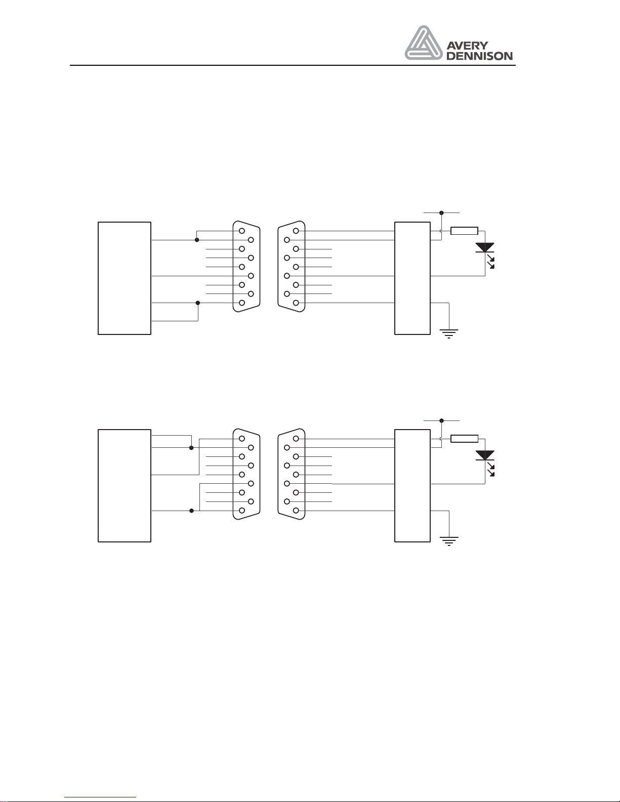
Operators Manual
ALS 330/430
Release 8/07 Page 62 Connections and signals
8.3.2 OD Control sensor
Optional an OD control could be mounted to control the label roll. If the label material is nearly
empty the sensor gives an signal. A warning message and an output signal inform the personal
that in the next time the material has to be changed.
+24V
GND
14
black
green
white
red
brown
5
9
4
8
3
7
2
6
1
Signal-
GND
Signal+
Supply
white
grey
blue
25
11
27
CN33E3JK-R2M2
NPN sensor
5
9
4
8
3
7
2
6
1
Figure 24 NPN connection of optional ODC sensor
+24V
GND
14
black
green
white
red
25
11
27
CN33
brown
5
9
4
8
3
7
2
6
1
Signal-
GND
Signal+
Supply
white
grey
blue
S5-5-C8-30
PNP sensor
5
9
4
8
3
7
2
6
1
Figure 25 PNP connection of optional ODC sensor
Page 71
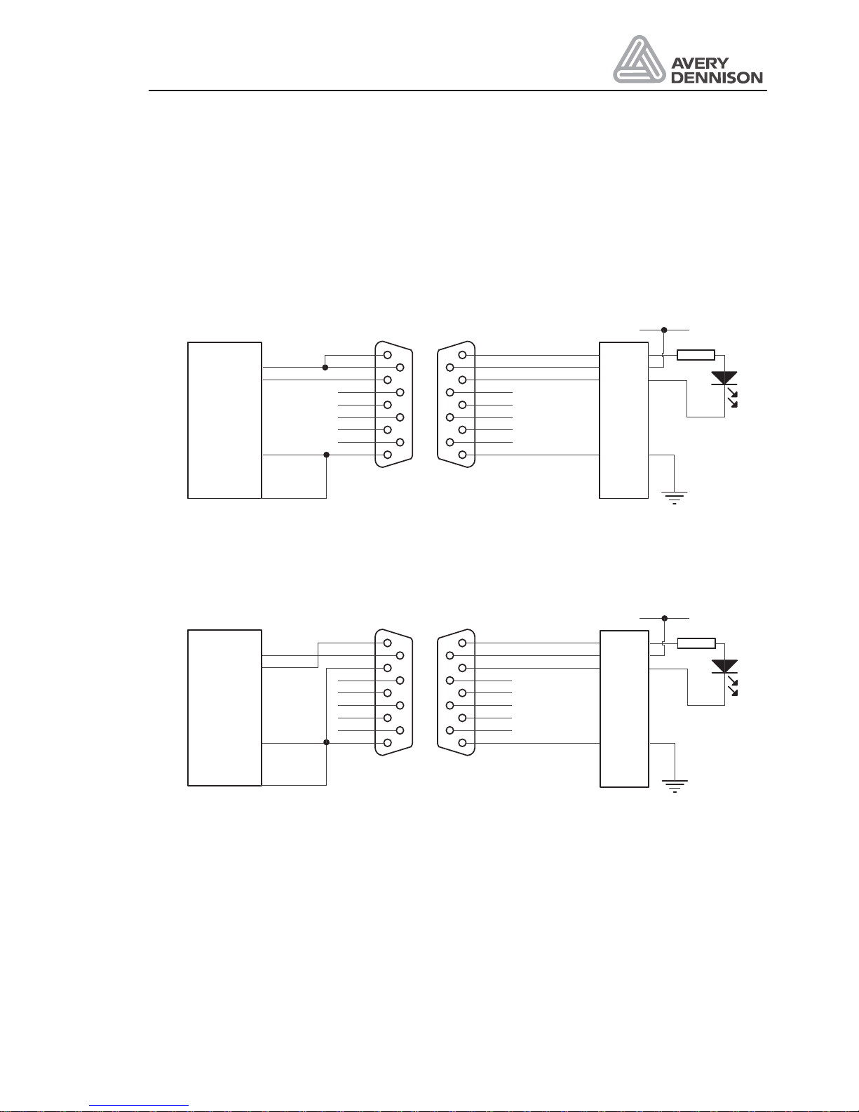
Operators Manual
ALS 330/430
Release 8/07 Page 63 Connections and signals
8.3.3 APSF sensor
For the APSF function (Automatic speed follower) a rotary encoder has to be installed. For
optimum labelling accuracy the rotary encoder should be selected so that it produces one pulse
for every 0.125 mm of product movement. The connection of the encoder should be done with
a shielded cable. For correct operation the rise and fall time of the encoder signal should be
1 µs.
+24V
GND
14
black
yellow
white
red
5
9
4
8
3
7
2
6
1
GND
Signal
Supply
Shield
12
33
27
CN33
NPN sensor
5
9
4
8
3
7
2
6
1
Figure 26 Connection of a NPN type APSF sensor
+24V
GND
14
black
yellow
white
red
12
33
27
CN33
5
9
4
8
3
7
2
6
1
5
9
4
8
3
7
2
6
1
GND
Signal
Supply
Shield
PNP sensor
Figure 27 Connection of a PNP type APSF sensor
Page 72
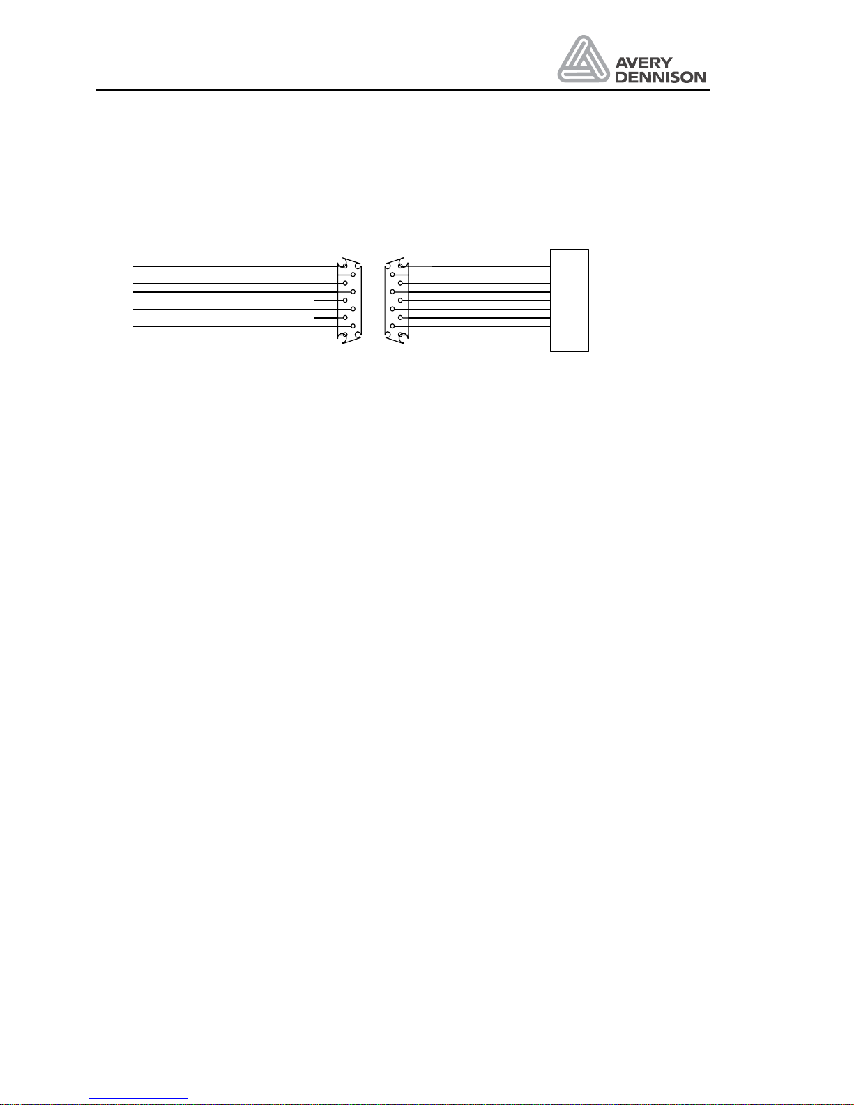
Operators Manual
ALS 330/430
Release 8/07 Page 64 Connections and signals
8.3.4 Control signals
An optional connector could be installed for integration of the machine in the line control.
5
9
4
8
3
7
2
6
1
5
9
4
8
3
7
2
6
1
CN33
red
green
black schwarz
rot
grün
+24 Volt +24 Volt
Ground M asse
Warning output Warnausgang
Error output Fehlerausgang
Inhibit - Startunterdrückung -
Inhibit + Startunterdrückung +
white weiß
blue blau
yellow gelb
21
27
7
20
19
14
brown
orange
violet
braun
orange
lila
TBD
TBD
31
Ready output Betriebsbereitschaft
Figure 28 Optional connector for process contro
Page 73
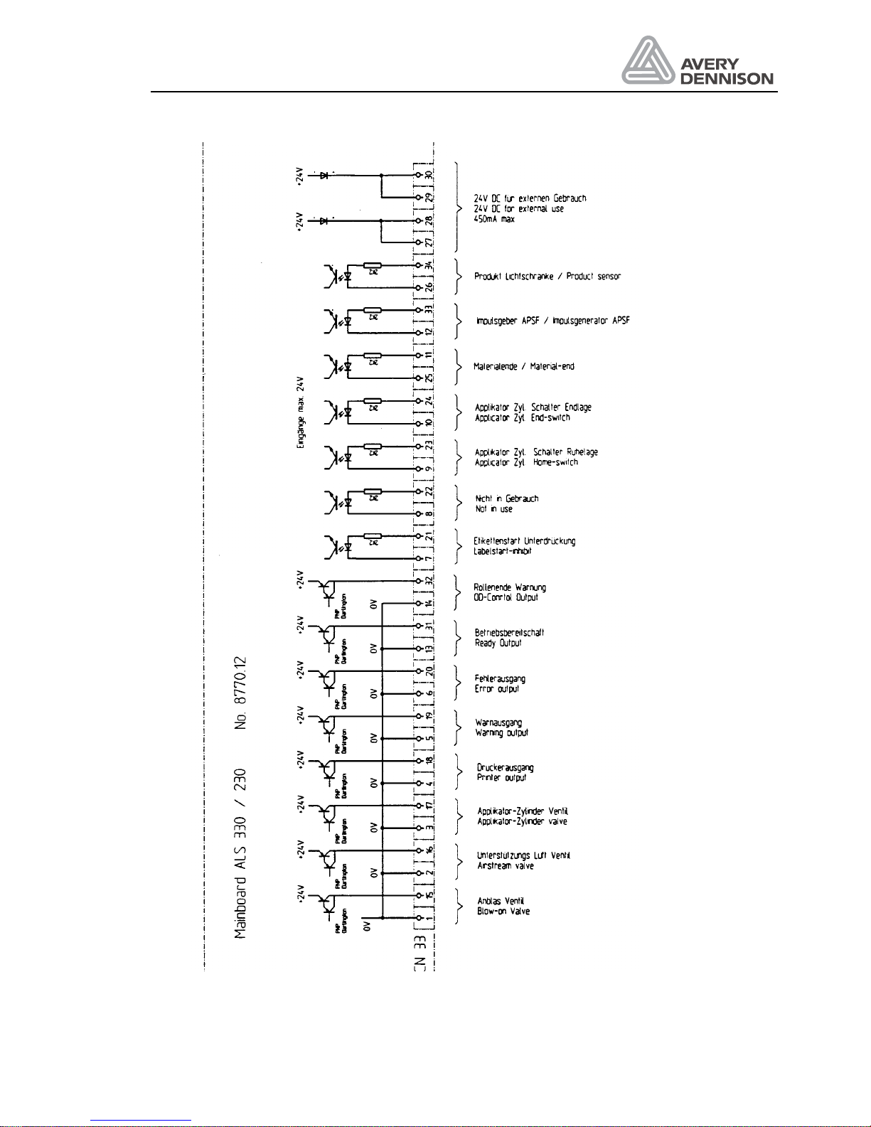
Operators Manual
ALS 330/430
Release 8/07 Page 65 Connections and signals
l
Figure 29 Internal I/O connector
Page 74

Operators Manual
ALS 330/430
Release 8/07 Page 66 Connections and signals
8.4 EMI
To protect the machines against electrical noise and to protect production of electrical noise
you have to follow this rules:
Rule 1
All metallic parts must have a good and plane contact (no lacquer, aluminium oxide is an
isolator). Use scratch washers.
Rule 2
Signal lines (Data- , communication- and control cable) has to separated to power cables. The
minimum distance is 50 cm (20 cm inside a cabinet).
Rule 3
All signal lines should be lead in the machine or cabinet only on one side.
Rule 4
Unshielded cables must be twisted (both poles).
Rule 5
On all inductive components (relays, valves) must be directly connected a clamp circuit (diode,
MOV).
Rule 6
All signal lines must be shielded. The shield must have a good earth connection on both
sides.
For the connection use metallic clamps. Don’t use a soldered wire for this connection.
In case of different earth potential on both cable sides install parallel a cable of at minimum 10
mm2.
Rule 7
The shield of analogue cable (Video etc) should be shielded only on one side. Normally there is
no such cable with labelling machines.
Rule 8
Line filter has to be mounted directly on the cable entry.
Rule 9
Cables should not fly in the air. Lead all cables nearby metallic, grounded parts. Ground
unused cables and wires in a cable at minimum on one side, better on both.
Rule 10
Cables should not be longer as necessary.
Page 75

Operators Manual
ALS 330/430
Release 8/07 Page 67 Connections and signals
8.5 Electronic diagrams
Page 76
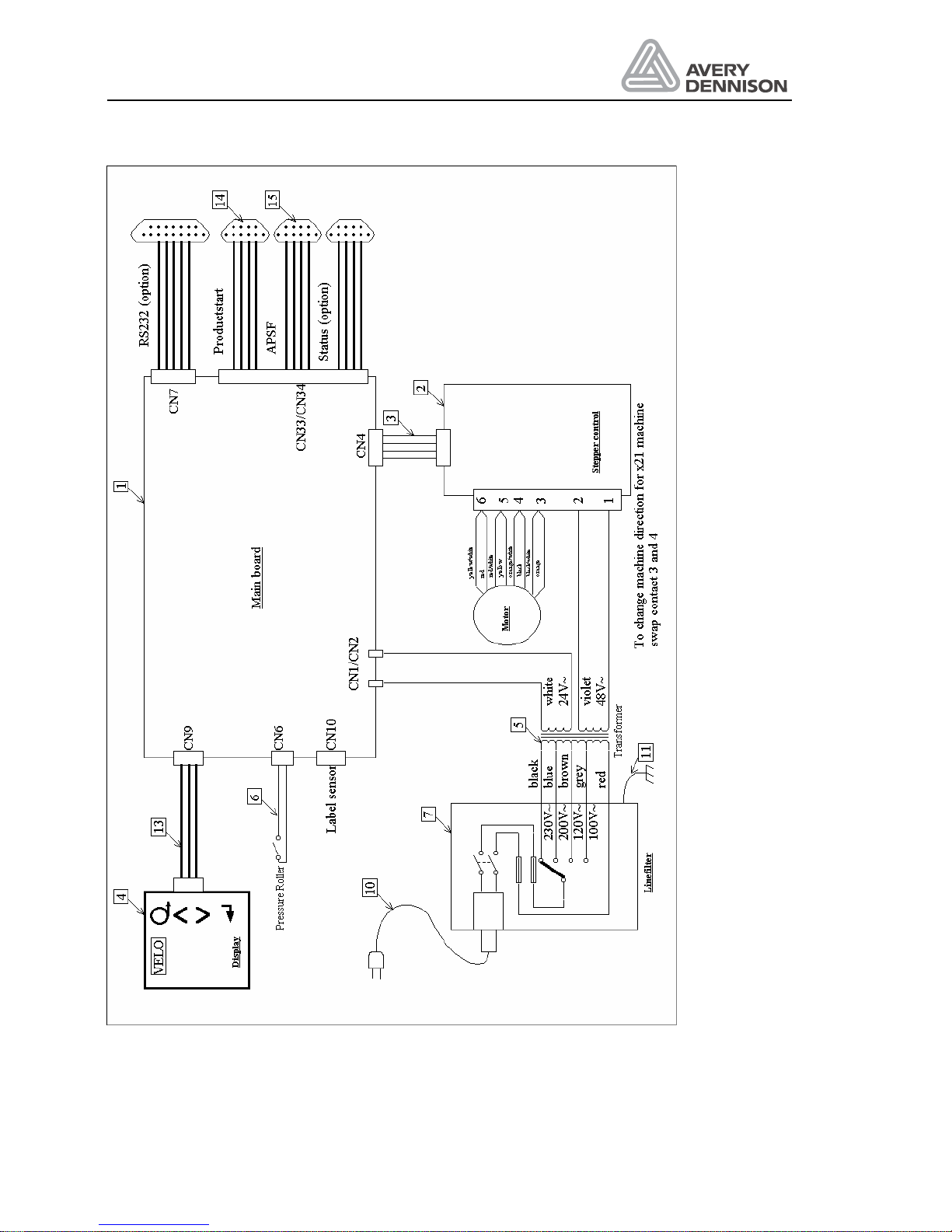
Operators Manual
ALS 330/430
Release 8/07 Page 68 Connections and signals
Figure 30 Wiring diagram
Page 77
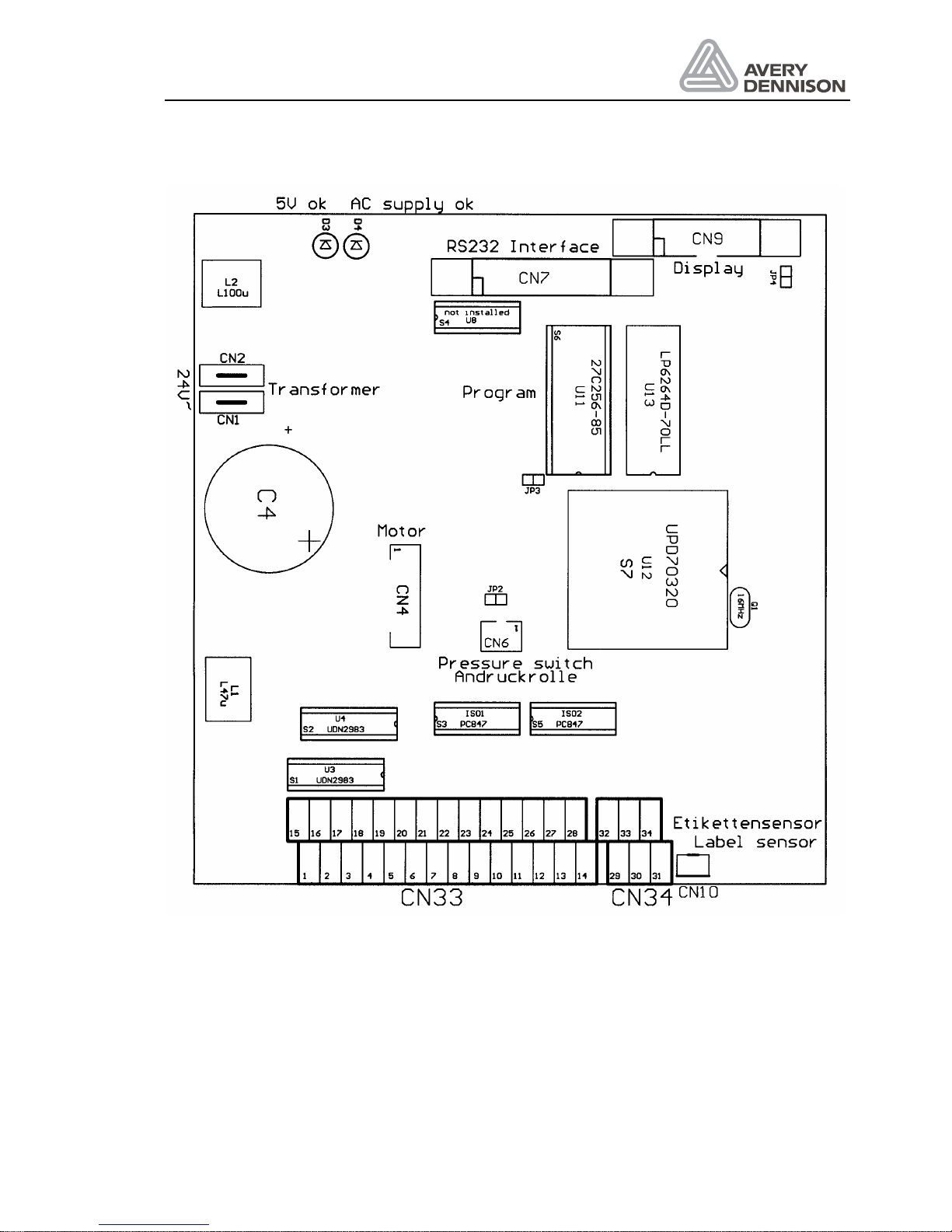
Operators Manual
ALS 330/430
Release 8/07 Page 69 Connections and signals
Figure 31 Layout dispenser electronic board
Page 78
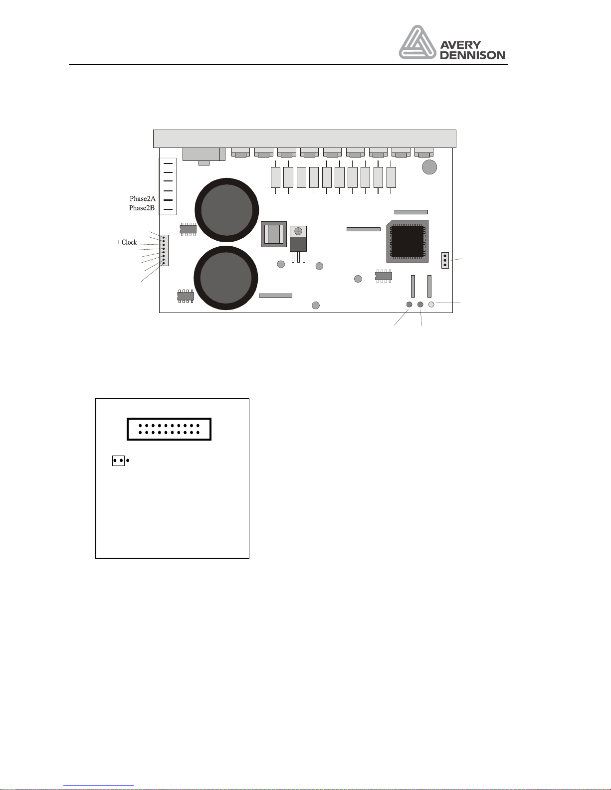
Operators Manual
ALS 330/430
Release 8/07 Page 70 Connections and signals
LED Voltage
Ready LED
Overtemperature 100% on
Short circuit 25% on / 75% off
Both 75% on / 25% off
+ Direction
- Direction
- NC
+ NC
- Clock
Ready Collector
Ready Emitter
48VAC
48VAC
Phase1B
Phase1A
800
400
Resolution
Figure 32 Layout stepper motor driver
JP
Figure 33 Display jumper setting
Page 79

Operators Manual
ALS 330/430
Release 8/07 Page 71 Connections and signals
Page 80

Page 81
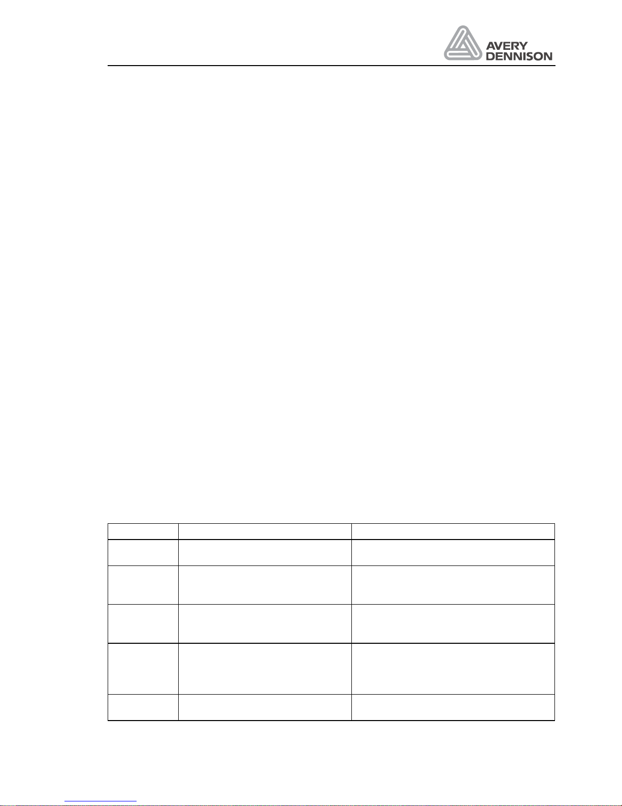
Operators Manual
ALS 330/430
Release 8/07 Page 73 Errors and warnings
9. Errors and warnings
The software checks during the labelling permanently, if the machine runs under normal
operation. If labelling is not possible, the display shows a message e.g. E__0.
If the labelling can be continued, but a problem has occurred or may occur, the display shows a
warning e.g. W__1.
By pressing the key ENTER the message will be erased.
In case of an error or warning message the relevant output is switched. The signal can be used
for interconnection with an external machine control.
Via the serial interface the errors and warnings can be called.
If an error cannot be erased, please call your local service technician.
9.1 Dispenser error messages
In case of an error message the relevant output is switched. The signal can be used for
interconnection with an external machine control.
STO! Power-fail message
The message STO! appears in the display as the machine is switched off or if the mains supply
voltage has fallen below specification.
The message STO! (store) indicates that the machine has stored some parameters internally
as a power fail condition was detected. The error output is switched active and the ready output
inactive simultaneously with STO! appearing in the display.
If the mains supply voltage only experiences a drop in level and then returns to a correct level
then the ready output is restored to its previous condition but the message STO! will remain in
the display to indicate that there has been a problem with the mains supply.
Message Meaning How to solve
E__0 Pressure roller is open Close the pressure roll and make a new
initialisation if necessary
E__1 During material transport no label
is recognised over a length of 4
labels
Insert new material and check the label
sensor
E__2 EP applicator not in HOME
position
Check air supply.
Applicator not connected.
HOME switch not adjusted
E__3 Check sum of the configuration
data is wrong. All Parameters are
set
to the factory adjustment.
Call the configuration menu and adjust
all parameters again.
E__4 Check sum of the labelling data is
wrong. Labelling Parameters are
All labelling parameter have to be
adjusted again
Page 82
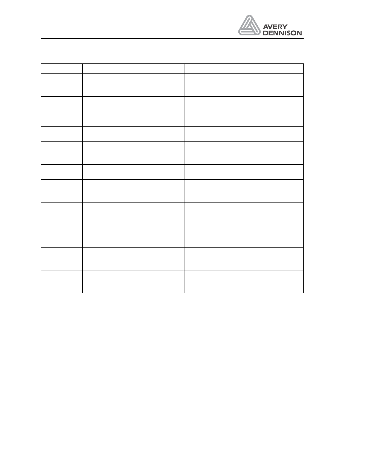
Operators Manual
ALS 330/430
Release 8/07 Page 74 Errors and warnings
Message Meaning How to solve
set to the factory adjustment.
E__5 10V supply voltage for label
sensor low.
Short circuit in label sensor or cable.
Voltage regulator U14 is damaged.
E__6 24V Voltage low Short circuit on an output. Total load too
high i.e. max is 3A for all outputs.
Voltage regulator U1 is damaged.
Change main board.
E__7 Material initialization failed Check if the label web is threaded
through the label sensor
E__8 Error stepper motor driver The stepper motor control has detected
an error. The fault is indicated by the
LED’s on the driver.
E__9 10V supply for label sensor too
high
Voltage regulator U14 damaged
E__10 Missing label on product One or several product could not be
labelled. Distance between products too
close. Increase speed of printer.
___0 Process error (Divide overflow) Hardware failure external noise. EPROM
damaged. Turn off power and on again.
Change EPROM or main board
___1 Illegal interrupt (processing error) Hardware failure external noise. EPROM
damaged. Turn off power and on again.
Change EPROM or main board
___2 Illegal bank interrupt (processing
error)
Hardware failure external noise. EPROM
damaged. Turn off power and on again.
Change EPROM or main board
INTO Illegal interrupt INTP0 (processing
error)
Hardware failure external noise. EPROM
damaged. Turn off power and on again.
Change EPROM or main board.
Page 83

Operators Manual
ALS 330/430
Release 8/07 Page 75 Errors and warnings
9.2 Dispenser warnings
In case of a warning message the relevant output is switched. The signal can be used for
interconnection with an external machine control. Warning W__5 activates only the special OD
warn output.
Message Meaning How to solve
W__0
New start signal from
product sensor while
ALX720 is dispensing a
label
Multiple signals from the
same product
Several missing labels on
the web, which can not be
compensated
Slow down conveyor speed or
product sequence.
Adjust higher labelling speed
Increase the parameter value
of PRDL product length
W__2
Error while writing in the
EEPROM
EEPROM defect, Start
machine again, if problem
remains the same, exchange
EEPROM as soon as possible
W__3 RS232 transfer error
Check interface parameter in
the configuration menu and in
the host
W__4
Conveyor speed exceeded
the max. speed of the
dispenser
Slow down conveyor. If
average conveyor speed is OK
then check for oscillation in the
conveyor speed or vibration of
the pulse generator
W__5
Material end by the OD
control recognised
Insert a new material roll
W__6
Too many products between
sensor and dispensing edge
Move the sensor closer to the
dispensing edge
Page 84

Operators Manual
ALS 330/430
Release 8/07 Page 76 Errors and warnings
Page 85
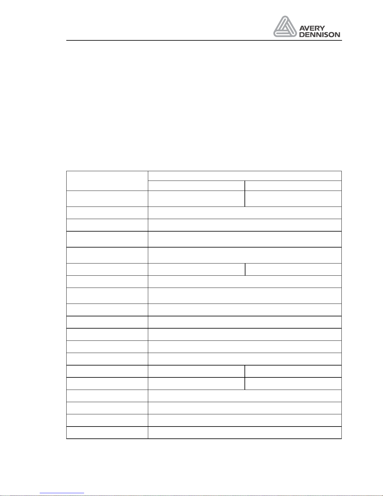
Operators Manual
ALS 330/430
Release 8/07 Page 77 Technical specification
10. Technical specification
The following data are maximum values. Depending on label material, operation environment
and labelling condition the real value could be lower.
10.1 Technical Information
Details
Description
330 430
Label width
(incl. backing paper)
10 mm ... 100 mm 10 mm ... 230 mm
Label length 5 to 999 mm
Diameter Label roll max 300 mm
Core diameter (of label
roll)
1.5" (37 mm), or 3" (74 mm) optional
Label roll unwind dancer arm controlled unwind brake, for minimum
change in web tension (Euro versions only)
Dispensing speed 0.2- 25 m/min 0.2- 18 m/min
Material transport 0.1 mm per motor step
APSFAutomatic Product
Speed Follower
optionalResolution: 0.1mm to 0.3 mm per pulse
Label stop accuracy +/- 0.5mm
Labels per min rate See performance charts
Rewind collapsible, i.e. can be used even for plastic backing material
Dispensing edge V-shape fixed; L - shape fixed (optional)
Versions available left and right hand
Dimensions w * h * d 560 * 630 * 340 mm 560 * 630 * 410 mm
Weight 28 kg 35 kg
Display panel 4 Digit LED display, 4 Membrane keys
Label sensor infrared photo sensor
CE- marked Confirms all relevant actual European standards
Protection class IP 41, IP54 on request
Page 86
Operators Manual
ALS 330/430
Release 8/07 Page 78 Technical specification
Details
Description
330 430
Operating environment 5 – 40°C, storage 0 – 70°C
30 - 80%, non condensing
Power consumption 300 VA
Mains voltage 100V~, 115V~, 200V~ and 230V~ 50/60Hz (6.3A for 110V else
3.15A),
+5%- 10%
10.1.1 Application specification
The labeller is designed and built for automatic applies of self-adhesive labels.
10.1.2 APSF- Sensor Specification (Optional function)
The resolution of the sensor should be selected in a way, that for 0.15mm product travel a
sensor pulse will be generated. Using a different resolution gives loose in label accuracy or
limits the highest dispensing speed.
It is possible to use one common sensor for several dispensers. In this case the sensor is
supplied from one machine or the several supply voltages switched parallel are separated with
diodes.
Supply voltage: 24 V DC
Output current: 20mA for each dispenser
Signal rise and fall time: each 1µs
Max frequency: 20 kHz
Signal ratio: 1:1 +- 12,5 %
Connection: Only shielded cable. The shield has to be grounded on both sides.
Page 87
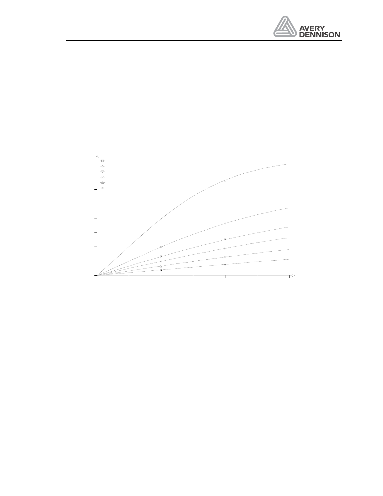
Operators Manual
ALS 330/430
Release 8/07 Page 79 Technical specification
10.2 Performance charts
The following charts show the maximal theoretically labels per minute rate. Tolerances in
product speed, label and product dimensions reduce the label rate. The charts are valid for
direct dispensing (without applicator and printer). For critical applications, performance test
should be done first. The charts are valid for software version V4.0.
10.2.1 Charts 330
0 5 10 15 20 25 30 m/min
labels/min
0
100
200
300
400
500
600
700
800 25 mm
50 mm
75 mm
100 mm
150 mm
250 mm
Figure 34 Performance chart: Ramp FAST
Page 88
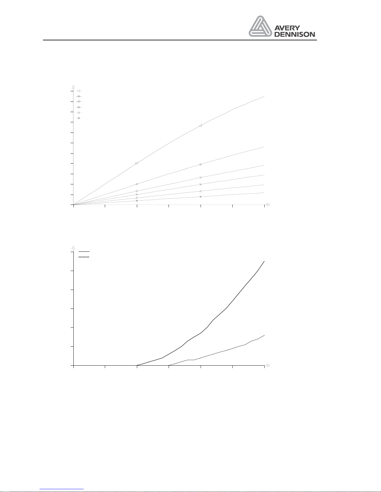
Operators Manual
ALS 330/430
Release 8/07 Page 80 Technical specification
0 5 10 15 20 25 30 m/min
labels/min
0
100
200
300
400
500
600
700
800
900
1000
1100 25 mm
50 mm
75 mm
100 mm
150 mm
250 mm
Figure 35 Performance chart: Ramp NORM
0 5 10 15 20 25 30 m/min
mm
0
1
2
3
4
5
6 Normal
Fast
Figure 36 Accelaration
Page 89
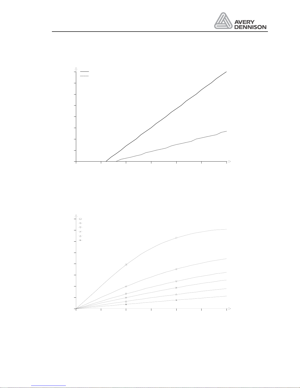
Operators Manual
ALS 330/430
Release 8/07 Page 81 Technical specification
0 5 10 15 20 25 30 m/min
mm
0
1
2
3
4
5
6
7
8 Normal
Fast
Figure 37 Deceleration
10.2.2 Charts 430
0 5 10 15 20 25 30 m/min
labels/min
0
100
200
300
400
500
600
700
800 25 mm
50 mm
75 mm
100 mm
150 mm
250 mm
Figure 38 Performance chart: Ramp FAST
Page 90
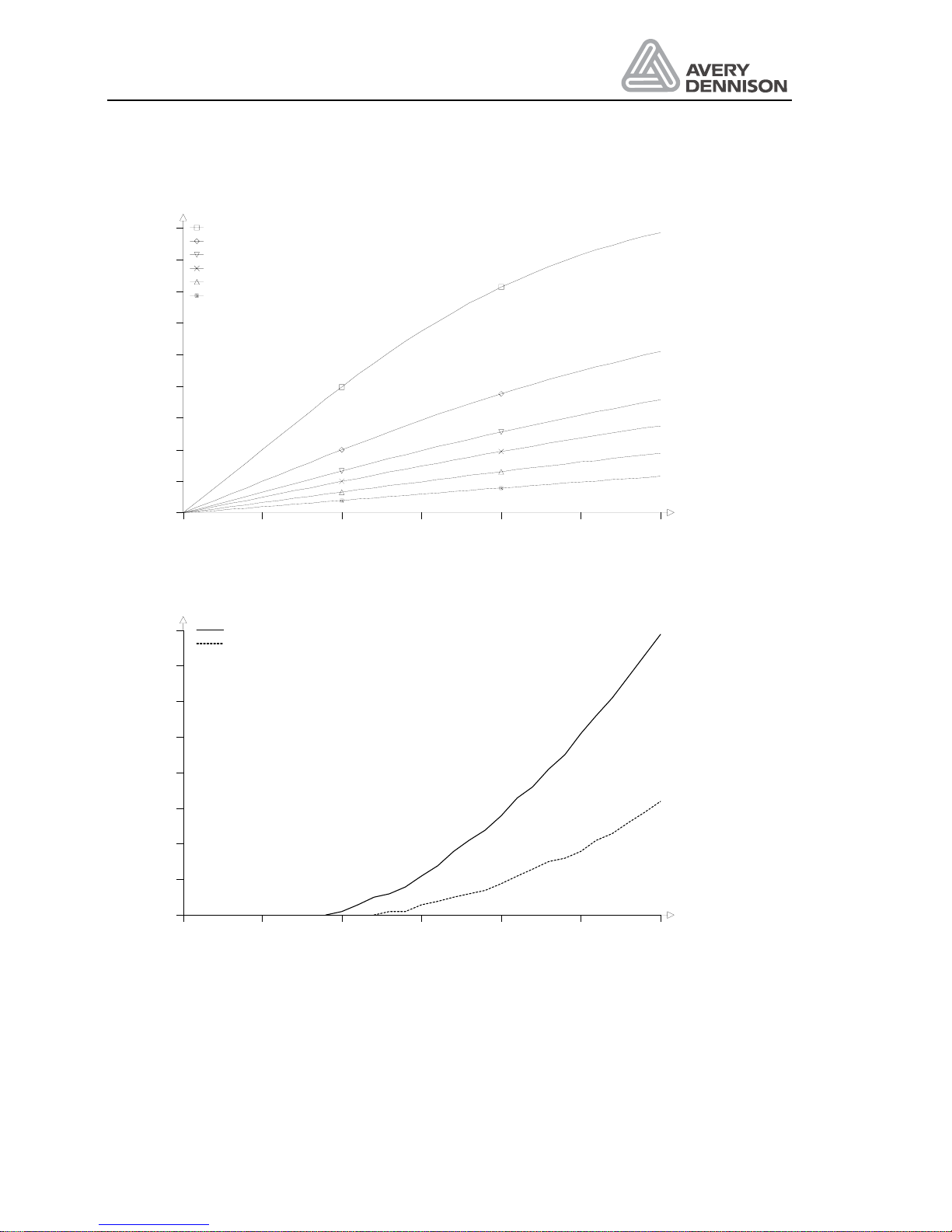
Operators Manual
ALS 330/430
Release 8/07 Page 82 Technical specification
0 5 10 15 20 25 30 m/min
labels/min
0
100
200
300
400
500
600
700
800
900 25 mm
50 mm
75 mm
100 mm
150 mm
250 mm
Figure 39 Performance chart: Ramp NORM
0 5 10 15 20 25 30 m/min
mm
0
1
2
3
4
5
6
7
8 Normal
Fast
Figure 40 Accelaration
Page 91
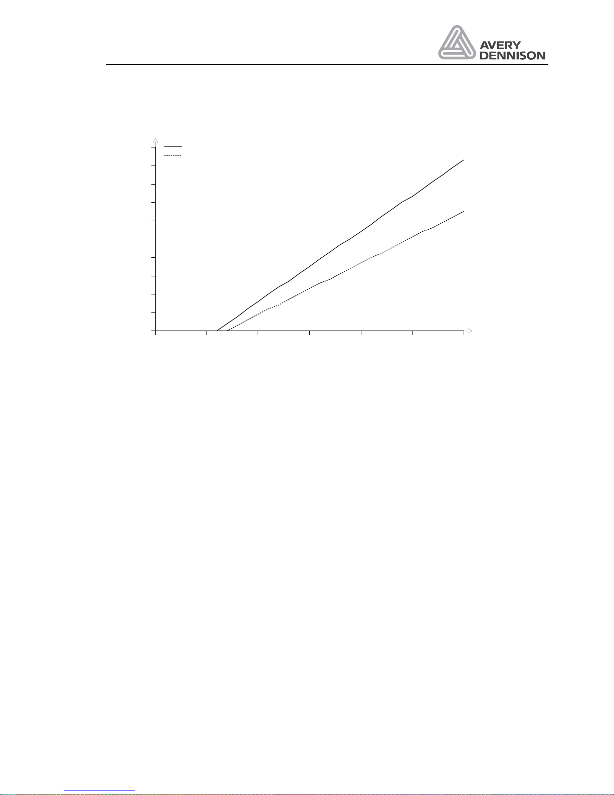
Operators Manual
ALS 330/430
Release 8/07 Page 83 Technical specification
0 5 10 15 20 25 30 m/min
mm
0
1
2
3
4
5
6
7
8
9
10 Normal
Fast
Figure 41 Deceleration
Page 92

Page 93

Operators Manual
ALS 330/430
Release 8/07 Page 85 Adjustment
11. Adjustment
Function Factory Application
P_S_ LEDG
MACH 230
MDIR Å
RAMP FAST
MLAB WARN
COMP ON
APSF OFF
APPL DIR
BAUD NONE
PARI NO
SBIT 2BIT
DBIT 8BIT
DIST 76.0 mm
PHT 1
SLEW FAST
Page 94

Operators Manual
ALS 330/430
Release 8/07 Page 86 Adjustment
Function Factory PD01 PD02 PD03 PD04
POS(STAD) 100.0 mm
VELO 30.0 m/min
STOD 76.0 mm
BLOW(APT2) 1 ms
LPIT AUTO
CONT AUTO
PRDL AUTO
EGRA 500
APT1 200 ms
APT3 0 ms
APOS 0
ASTP 0
PDT OFF
Function PD05 PD06 PD07 PD08 PD09
POS(STAD)
VELO
STOD
BLOW(APT2)
LPIT
CONT
PRDL
EGRA
APT1
APT3
APOS
ASTP
PDT
Page 95

12. Index
A
applicator 57, 59
Applicator 46
APSF 44, 46, 63
ASA 57
Automatic product speed follower Siehe
APSF
C
capacitve label 20
configuration menu 43
Configuration menu 37
D
Direction 45
DIST 49
DTST Siehe Permanent test
E
EP applicator 58
Extended standard menu 37
F
factory values 48
I
interface 48, 51
L
Labelling position 53
M
MACH Siehe Machine type
Machine type 45
missing label 45
O
OD control 62
OD-Control 55
Output check 47
P
password 43
permanent test 45
printer 55
product menu 47
Product menu 37
product sensor 14, 30, 32, 33, 40, 43, 44, 47,
45, 53, 60, 75
R
ready 55
S
sensor check 47
serial interface 51, 73
Standard menu 37
Stop position 39, 40, 41, 43, 53
Label counter 49
 Loading...