

Page 1
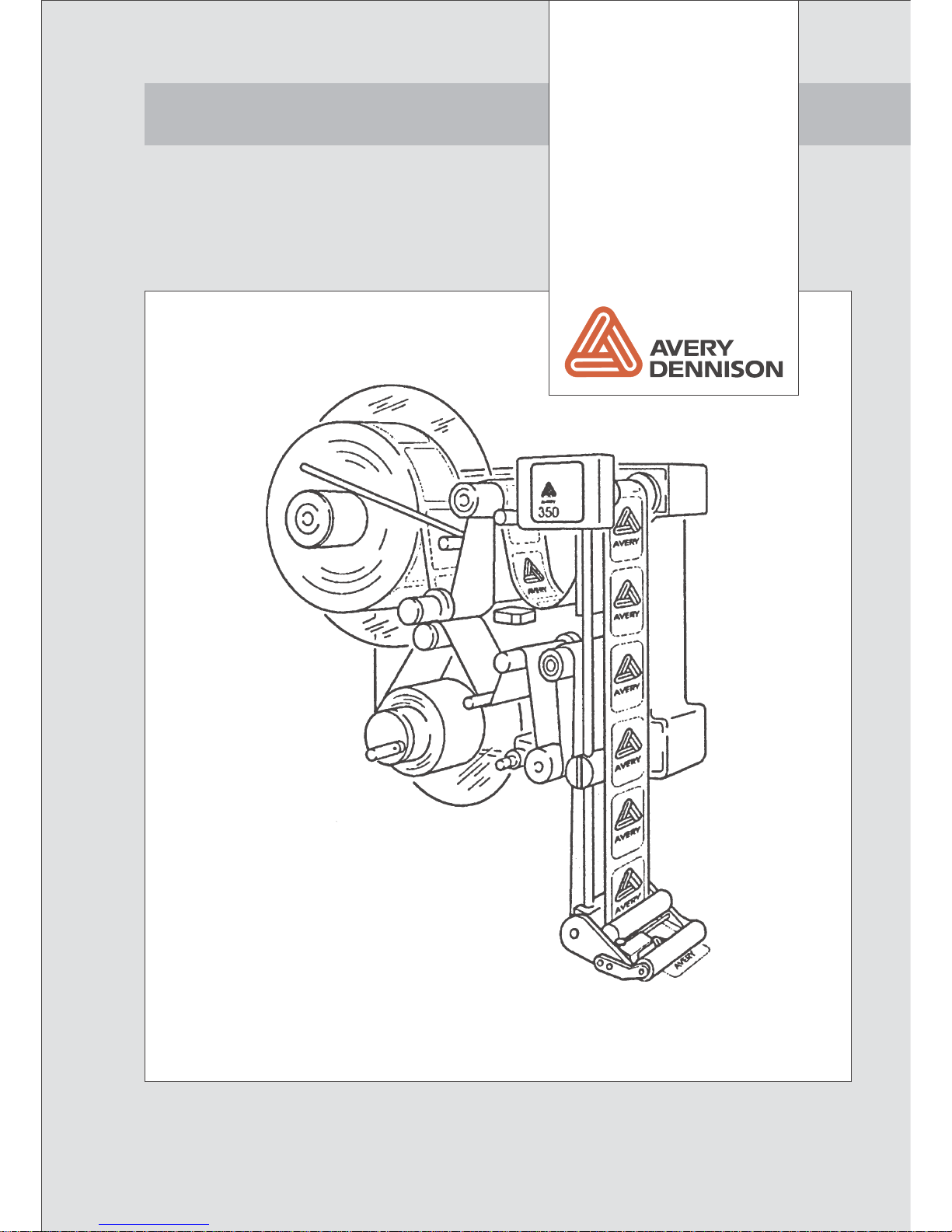
ALS 341
User Manual
...Covering the World
Part number 0089999-10
Release 4/04
Page 2

Page 3

Operators Manual
ALS 341
Release 4/04 Page i Contents
Contents
1. Important Notes........................................................................................................1
1.1 Overview.......................................................................................................................................1
1.1.1 Manufacturer......................................................................................................................1
1.1.2 Copyright............................................................................................................................ 1
1.2 Safety notes..................................................................................................................................2
General Safety Notes................................................................................................................... 2
Warning Notes in the Text............................................................................................................ 2
1.2.1 Operator’s duty of care...................................................................................................... 3
1.2.2 Concrete security regulations and symbols used..............................................................4
1.2.3 Security measures during normal operation...................................................................... 5
1.2.4 Security measures during maintenance and repairs......................................................... 5
1.2.5 Work on the electrical equipment ...................................................................................... 6
1.2.6 Work on pneumatic equipment..........................................................................................6
1.2.7 Observe environmental regulations................................................................................... 6
2. Short form instruction...............................................................................................9
2.1 Operator panel..............................................................................................................................9
2.2 Service menu..............................................................................................................................10
2.2.1 Handling the service menu ..............................................................................................10
3. Starting the labeller ................................................................................................12
3.1 Installation ..................................................................................................................................12
3.1.1 Unpacking of the unit....................................................................................................... 12
3.1.2 Connection of the machine.............................................................................................. 12
3.1.3 General setting ................................................................................................................12
3.2 Mounting a new label roll............................................................................................................13
3.3 Setting the applicator roller.........................................................................................................15
3.4 Changing the position of the dispensing edge ...........................................................................15
3.5 Adjustment of the contrast..........................................................................................................16
3.5.1 Capacitive label sensor....................................................................................................17
3.6 Label guide................................................................................................................................. 18
3.7 Adjust dispense function............................................................................................................. 18
3.7.1 Stop position.................................................................................................................... 18
3.7.2 Labelling speed................................................................................................................19
3.7.3 Label position on the product........................................................................................... 19
4. Operation ...............................................................................................................20
4.1 Direct functions........................................................................................................................... 20
4.2 Service menu..............................................................................................................................21
4.2.1 Calling the menu.............................................................................................................. 21
4.2.2 Working with the service menu........................................................................................ 21
4.2.3 Menu functions ................................................................................................................22
Page 4

Operators Manual
ALS 341
Release 4/04 Page ii Contents
5. Messages and Troubleshooting............................................................................. 27
5.1 Warnings.....................................................................................................................................27
5.2 Error messages...........................................................................................................................28
5.2.1 Processor error ................................................................................................................29
5.3 Trouble shooting .........................................................................................................................29
6. Electrical connections ............................................................................................ 31
6.1 Power supply ..............................................................................................................................31
6.2 Location of the electronic control boards....................................................................................32
6.3 Stepper motor control .................................................................................................................33
6.4 CPU - board................................................................................................................................34
6.5 Display ........................................................................................................................................35
6.6 Description of I/O signals............................................................................................................36
6.7 EMI..............................................................................................................................................39
7. Maintenance...........................................................................................................41
7.1 Cleaning......................................................................................................................................41
7.2 Adjustment of rewind function.....................................................................................................41
8. Technical Specification ..........................................................................................43
8.1 Application specification..............................................................................................................44
8.2 Advice for security.......................................................................................................................44
8.3 Performance ...............................................................................................................................44
9. Index......................................................................................................................45
10. CE Declarations..................................................................................................... 46
Page 5

Operators Manual
ALS 341
Release 4/04 Page 1 Important Notes
1. Important Notes
1.1 Overview
The Avery ALS341/441 are fully automatic labeller. Operating is easy and can be learned with
a minimum of training. The labeller is controlled by a microprocessor allowing the labeller to be
programmed for use in a variety of labelling environments. Except for cleaning the rollers and
photo-sensors no other regular maintenance is necessary.
This manual should help you to operate the machine.
For technical questions, particularly in case of problems, your local AVERY organisation will be
pleased to help you.
1.1.1 Manufacturer
This machine was built by:
AVERY Maschinen GmbH
Ohmstraße 3
85385 Eching
Germany
Tel. +49-(0)8165-925-0
FAX +49-(0)8165-3143
1.1.2 Copyright
© 2004 Avery Maschinen GmbH. All rights reserved. No part of this work covered by Avery's
copyright may be reproduced or copied in any form or by any means (graphic, electronic or
mechanical, including photocopying, recording, recording taping, or information and retrieval
systems) without the written permission of Avery Maschinen GmbH. Avery also reserves all
other rights, including the right to make changes or corrections at any time without notice.
Avery make no representation or warranties about the accuracy, currency, completeness or
suitability of the information provided herein and will not be held liable for any use of this
information for any purpose. It is provided "as is" without express or implied warranty.
AVERY and all other related brands and product names are trademarks of Avery Dennison
Corporation. No licence to use or reproduce any of these trademarks or other trademarks of
Avery Dennison Corporation is given or implied. All other brand and product names are the
trademark of their respective owners.
Page 6

Operators Manual
ALS 341
Release 4/04 Page 2 Important Notes
1.2 Safety notes
General Safety Notes
Warning Notes in the Text
In this description, two types of notes can be found:
y Warning note – indicates a possible risque of injury for the user. Ignoring the warning can
lead to injuries or material damages.
Example:
CAUTION! - The machine is connected to mains. Only authorised
personnel may open the cover. Operation without this cover is not
allowed.
y Special advice regarding the carrying out – please notice!
Example:
Note: Please take note of the given notes and advices. They serve your safety
as well as the preservation of value of the machine.
Page 7
Operators Manual
ALS 341
Release 4/04 Page 3 Important Notes
1.2.1 Operator’s duty of care
The machine was designed and constructed taking into account a
hazard analysis and after careful selection of the harmonised
standards to be observed, as well as other technical specifications.
Thus, it corresponds to the state of the art and allows the highest
possible degree of safety during operation.
The safety of the machine, however, can only be put into operating
practice if all measures required for the safety are taken. It falls within
the operator‘s duty of care to plan these measures and to verify their
implementation.
Above all, the operator must make sure that
• the machine is only used in accordance with its purpose (cf. the
section “Use in accordance with the purpose” in the chapter
“Specification”)
• the machine is only operated in faultless serviceable condition
and that especially the safety devices are regularly checked with
respect to their serviceability
• the required personal protective clothing and equipment for
operating, maintenance and repair personnel are available and
are being used
• a legible and complete copy of the operating instructions is always
available at the place of operation of the machine
• only personnel which is qualified and authorised for it will operate,
service, and repair the machine
• this personnel is instructed in all relevant issues of occupational
safety and environmental protection on a regular basis and is
familiar with the operating instructions and especially the safety
instructions contained therein
• all safety and warning instructions on the machine itself are not
removed and are legible
Page 8
Operators Manual
ALS 341
Release 4/04 Page 4 Important Notes
1.2.2 Concrete security regulations and symbols used
In the following operating instructions, concrete security regulations are indicated in order to
point out the remaining risks which cannot be avoided when operating the machine. These
remaining risks include danger to
• Persons
• Product and machine
• Environment
The symbols used in the operating instructions are above all intended to point out the security
regulations!
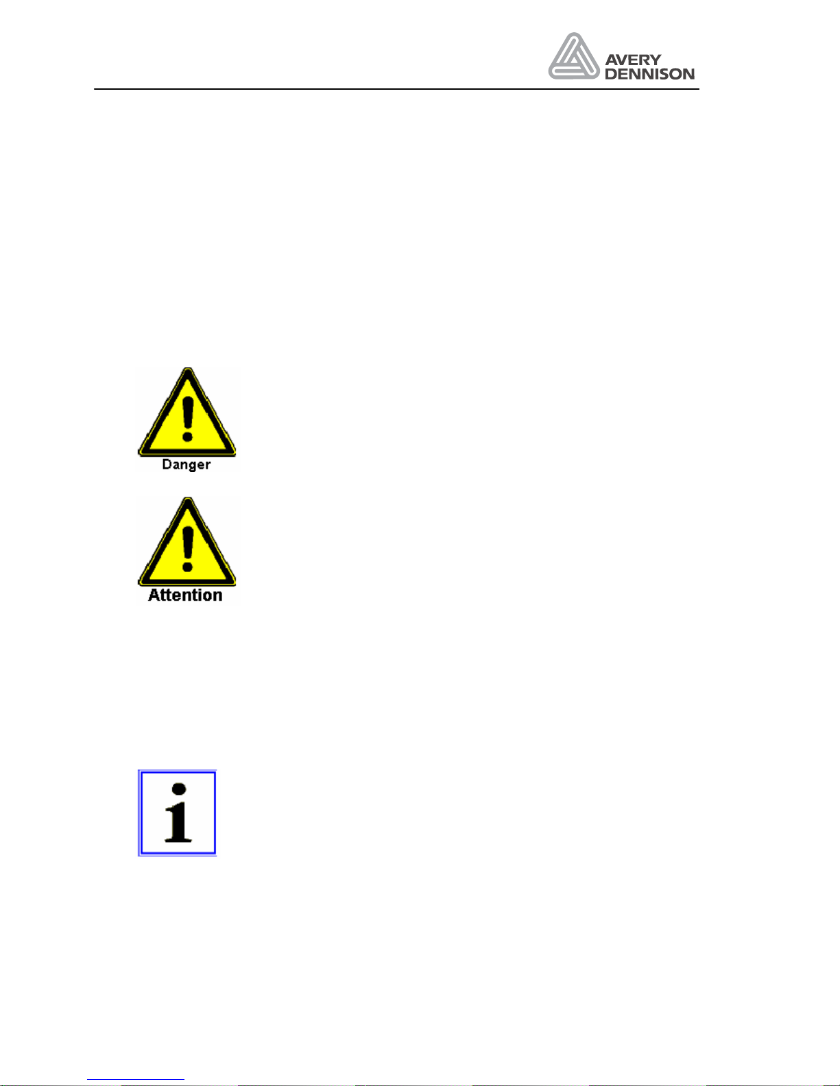
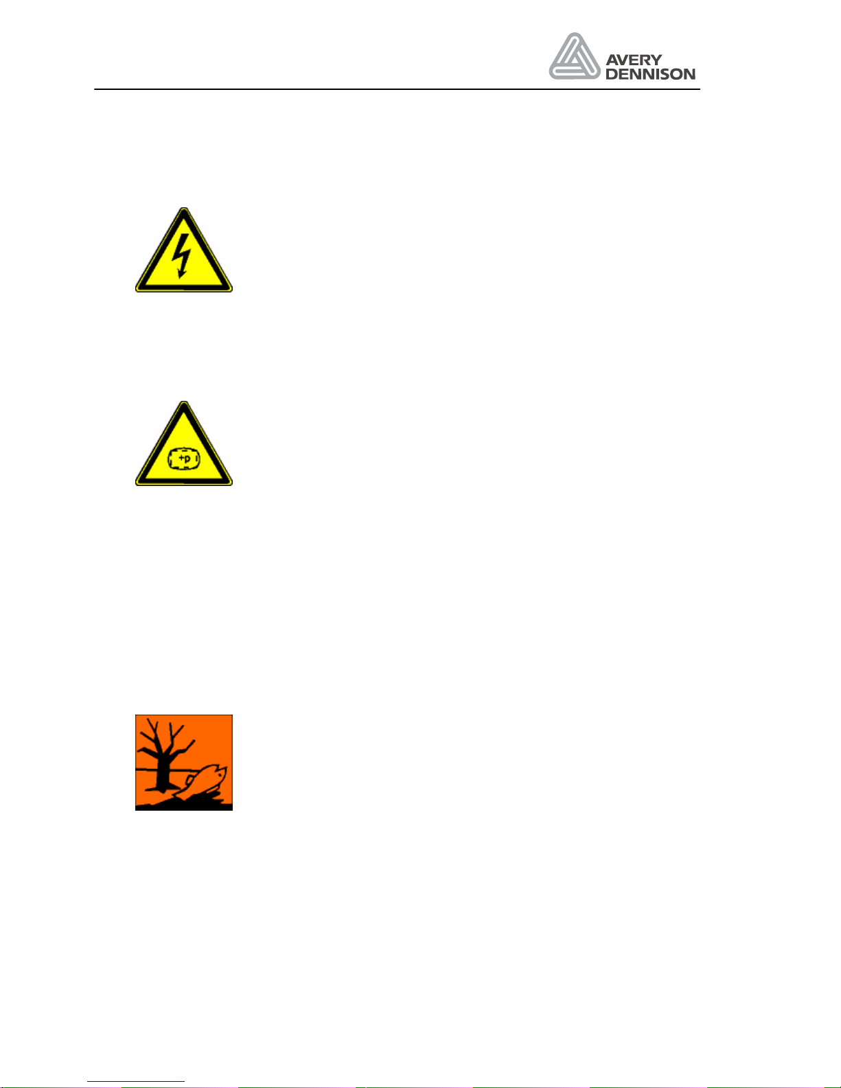
This symbol indicates that especially danger to persons has to
be expected.
(Lethal danger, danger of injury)
This symbol indicates that especially danger to the machine, material,
and the environment has to be expected.
The most important aim of the security regulations is to avoid injuries to a person.
• Whenever there is a warning triangle with the caption “Danger” in front of a security
regulation, dangers to the machine, materials, and the environment are not excluded.
• Whenever there is a warning triangle with the caption “Warning” in front of a security
regulation, a danger to persons, however, must not be expected.
The symbol used in each case, however, cannot replace the text of the security instruction.
Thus, it is necessary to always read the text completely!
This symbol does not indicate security regulations, but provides
information for a better understanding of the machine’s operations.
Page 9
Operators Manual
ALS 341
Release 4/04 Page 5 Important Notes
1.2.3 Security measures during normal operation
The machine may only be operated by trained and authorised persons
who are familiar with the operating instructions and are able to work in
accordance with it!
• Before starting the machine, check and make sure that
• only authorised personnel is staying in the operating area of the
machine
• Nobody can get hurt when the machine is started!
• Before every production start-up, the machine must be checked for
visible damage and it must be made sure that it is only operated in
faultless working condition! Any defects found must be immediately
reported to the supervisor!
Before every production start-up, all materials/objects that are not
necessary for production must be removed from the operating area of
the machine!
Before every production start-up, it must be checked and made sure that
all safety devices function in a correct manner!
1.2.4 Security measures during maintenance and repairs
Inspection and maintenance periods laid down in the operating
instructions must be observed!
Observe maintenance and repair instructions in these operating
instructions, which refer to individual components!
Before performing maintenance and repair work, the access to the
operating area of the machine must be prohibited for unauthorised
personnel! Post or put up a sign, which indicates the maintenance, or
repair work!
Before performing maintenance and repair work, turn off the main switch
for the electric power supply and secure it with a padlock!. The key to
this padlock must be in the hands of the person who performs the
maintenance or repair work!
When exchanging heavy machine parts, use only suitable and faultless
load suspension devices and stopping devices!
Page 10
Operators Manual
ALS 341
Release 4/04 Page 6 Important Notes
1.2.5 Work on the electrical equipment
Repair work on the electrical equipment of the machine may only be
performed by a trained electrician!
Electrical equipment must be checked on a regular basis!
Loose connections must be fixed again!
Exchange damaged lines/cables immediately!
Always keep the switch cabinet closed! Access is only allowed to
authorised personnel with keys/tools!
Never wash down switch cabinets and other housings of electrical
equipment with a water hose for cleaning!
1.2.6 Work on pneumatic equipment
Maintenance and repair work on pneumatic equipment may only be
performed by specially trained personnel!
Before starting maintenance and repair work, depressurise the
pneumatic equipment of the machine!
By way of precautionary maintenance, exchange hose pipes on a
regular basis, even if there is no damage to be detected!
(Observe the manufacturers’ instructions!)
Before setting into operation after maintenance or repair works
• check if loosened screwed connections are tight
• make sure that removed coverings are re-installed
After termination of maintenance and repair work and before re-starting
the production, make sure that
• all materials, tools, and other equipment required for maintenance
and repair work are removed from the operating area of the plant
• all safety devices of the plant function in a faultless manner!
1.2.7 Observe environmental regulations
During any and all work on and with the machine, the statutory duties
concerning prevention of waste and the proper waste disposal/recycling
regulations must be observed.
Especially in the case of installation, repair and maintenance work,
substances which are hazardous for the water, such as detergents
containing dissolvents, may not pollute the soil or get into the sewage
system!
These substances must be stored, transported, collected, and disposed
of in appropriate containers!
Page 11

Operators Manual
ALS 341
Release 4/04 Page 7
Page 12

Page 13
Operators Manual
ALS 341
Release 4/04 Page 9 Short form instruction
2. Short form instruction
This chapter contains a short instruction to handle the machine.
CAUTION! - The machine is connected to mains. Only authorised personnel
may open the cover. Operation without this cover is not allowed.
Note: This manual applies to ALS341/441 machines equipped with software
version 4.3 or higher.
2.1 Operator panel
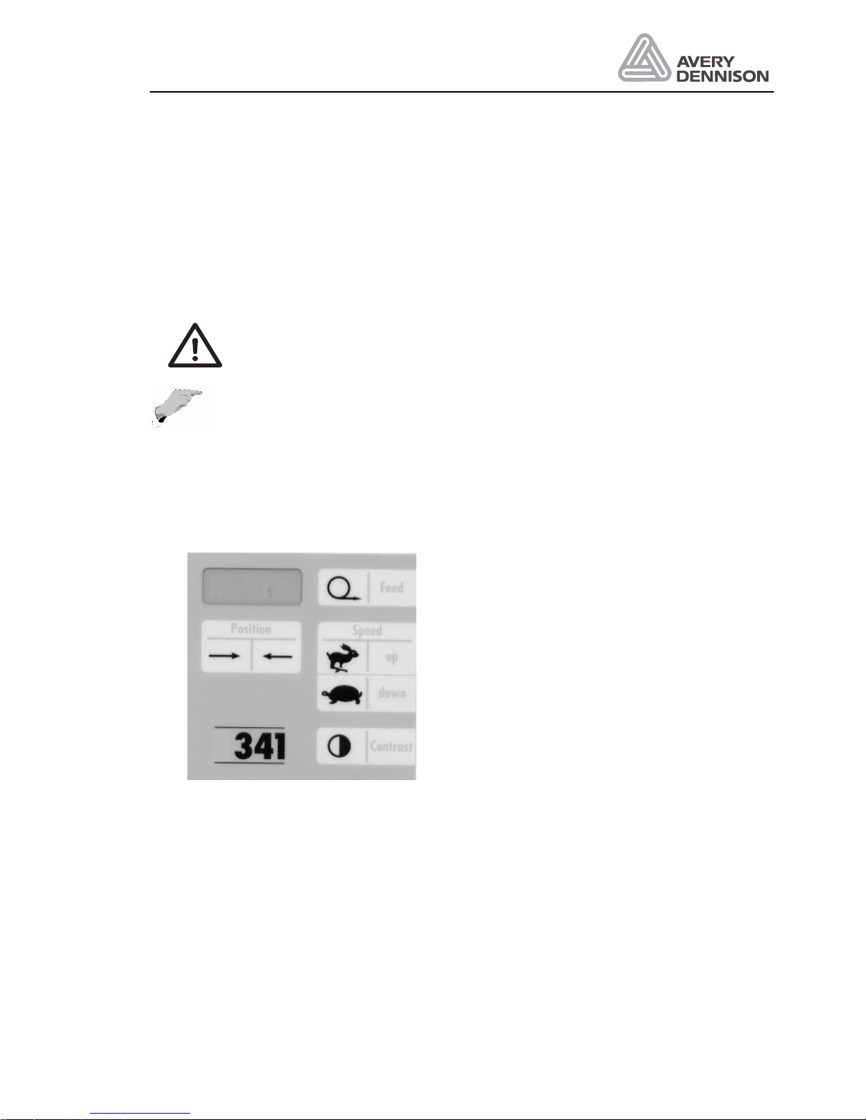
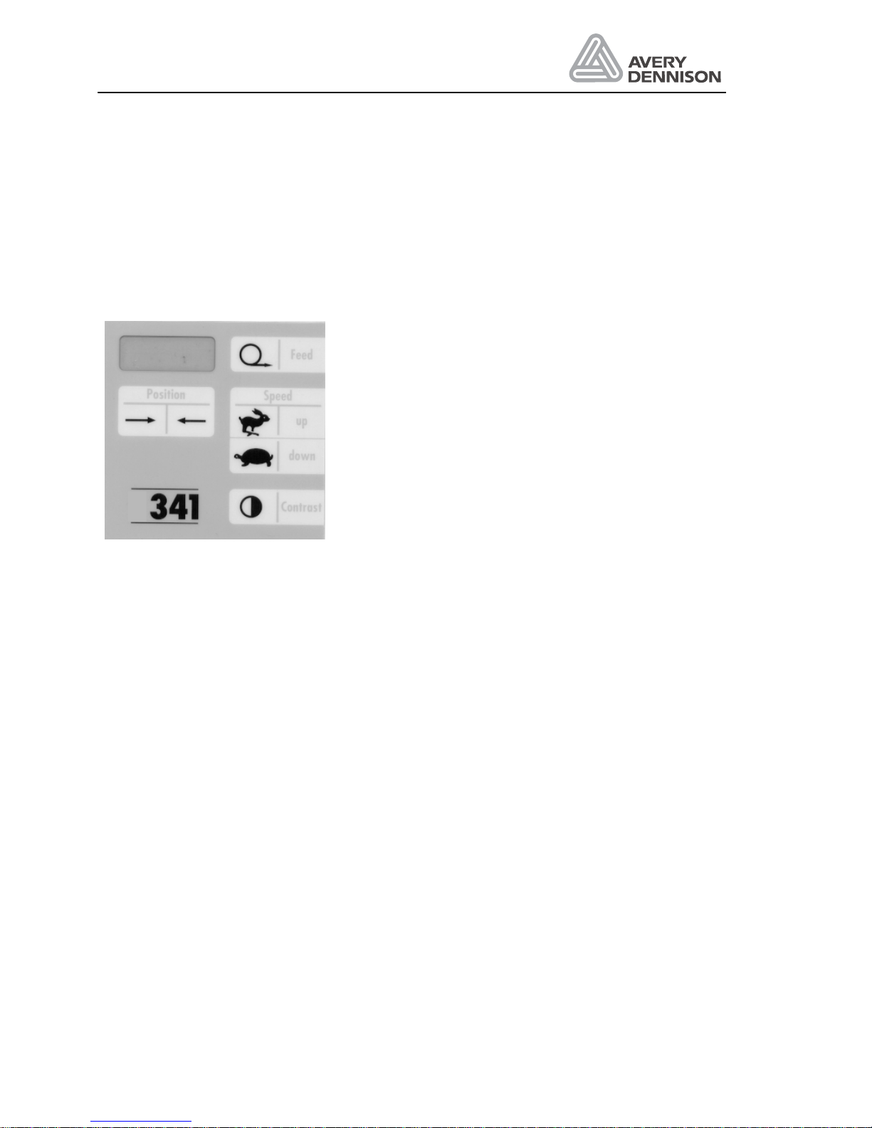
During normal operation the keys on the panel has the following functions:
Figure 1 Operating panel
Feed: Dispense one label. Used to position the labels correct, after threading new
material or fixing an error situation.
Speed: Setting the dispensing speed faster (up) or slower (down). The display shows
S250, which means a dispense speed of 25.0 m/min. With the both keys a value
from 2m/min up to 55m/min can be set.
Position: Adjust the position of the label onto the product. The display message 0500
means that the dispensing will be started 50.0 mm after triggering the product
sensor by the product. Pressing the key Æ decrease the shown value. The label
Page 14

Operators Manual
ALS 341
Release 4/04 Page 10 Short form instruction
will be placed closer to the front side of the product. The possible variation of the
value is 10mm up to 999.9mm.
Contrast: This function adjusts the sensitivity of the standard optical label sensor. If the
function is called, the display shows maybe CX30. The C indicates that the
Contrast function is active. In this mode, the machine doesn’t react to a
product start. The X appears in the display when the label sensor detects a label
on the label web. The X in the display corresponds to the yellow LED on the label
sensor.
The value (0-63) represents the sensitivity of the sensor.
To change contrast values press the Contrast key. If you hold the key for
approximately one second, the counting direction in the display reverses.
2.2 Service menu
In these menu settings can be done to configure the machine. In addition, some test functions
are available. The access to this menu is protected by a password.
y The sequence to enter the password will be started by pressing simultaneously both speed
keys.
y If CODE is displayed enter the password:
1 * Speed up
2 * Speed down
3 * Contrast
These are the functions within the service menu:
P_S_ Selection leading or trailing edge of product start sensor
S_S_ Selection leading or trailing edge of label start sensor
PRDL Product length (to disable multiple label starts)
ON3F Enable error message for rewinder
LOOP Loop speed control: Fast (250) or smooth (2000) speed
MDIR Machine dispense direction
DTST Continuos test
I_CH Input check
O_CH Output check
RWCH Position dancer arm of rewinder
LABC Label counter
QUIT Leave menu
2.2.1 Handling the service menu
Select a function: Press FEED key
Select value of a function: Press Contrast key
Change value of a function: Press FEED key
Back to select a function: Press Contrast key
Page 15

Operators Manual
ALS 341
Release 4/04 Page 11 Short form instruction
Leave service menu: Press Contrast key until QUIT is displayed, then
press Contrast key again.
Page 16

Operators Manual
ALS 341
Release 4/04 Page 12 Starting the labeller
3. Starting the labeller
In this chapter, the steps to prepare the machine will be described.
3.1 Installation
3.1.1 Unpacking of the unit
• For removing the unit off the box, don’t hold the machine on the dispensing edge to prevent
disadjustment off the machine.
• For mounting the machine, a complete system of holding tools is available. Ask your
representative.
• Take care that the machine is safe and stable mounted.
• There are rotating parts on the machine. Do the necessary actions to prevent that anybody
can be caught from these parts.
3.1.2 Connection of the machine
Before connecting the machine to the mains, check the correct setting of the line voltage. For
the connection of sensor, applicators e.g. see the chapter connections. Fix all cables to prevent
accidents and damaging of cables. Have also a look to the EMI chapter for proper machine
operation.
For checking of correct operation of sensor’s, applicators use the check functions I_CH, O_CH
and RWCH.
3.1.3 General setting
Normally the setting is done, but before operation check and note the general dispenser
configuration: dispenser direction, sensor polarity.
Page 17
Operators Manual
ALS 341
Release 4/04 Page 13 Starting the labeller
3.2 Mounting a new label roll
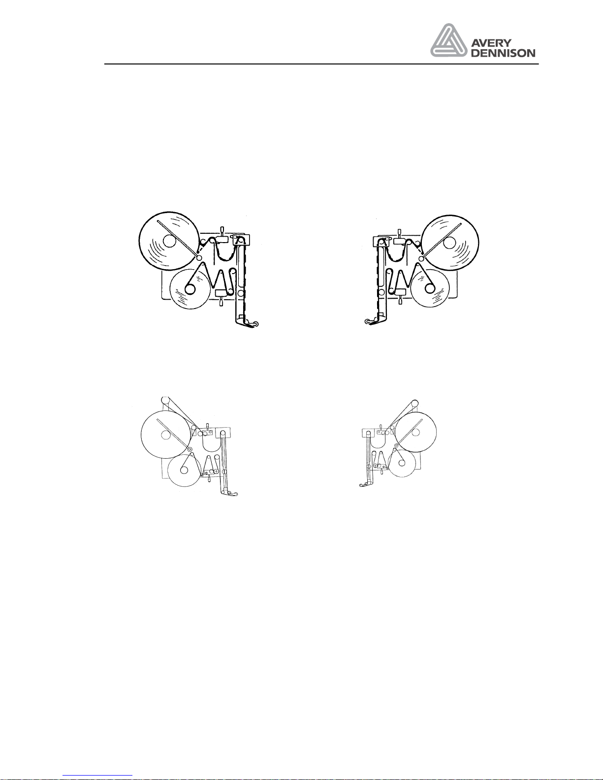
The threading path of the labelling material through the labeller is shown in the diagrams below.
A threading diagram is also affixed to the machine’s front-plate for easy reference.
Figure 2 Threading diagram Type 341
Figure 3 Threading diagram Type 441
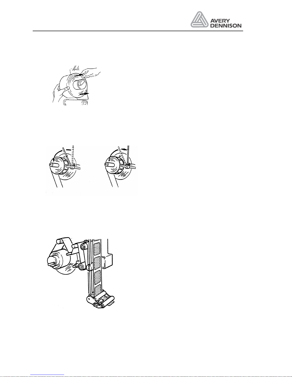
Before threading the new material, any waste backing paper should be removed from the
rewind mandrel as shown in the diagram below.
Turn the lever to retract the expandable pads. The waste backing paper can now be easily
pulled off the rewind mandrel.
Page 18
Operators Manual
ALS 341
Release 4/04 Page 14 Starting the labeller
Figure 4 Rewind
Swing the retainer arm away from the unwind mandrel and take off the old label roll. Push the
new label roll onto the unwind mandrel. Swing the retainer arm back onto the unwind mandrel
Figure 5 Unwind ALS 341
After threading the backing paper around the roller and shaft of the dancer-arm next to the
rewind mandrel, insert the edge of the backing paper into the slot of the rewind mandrel and
clamp it there by turning the lever.
Figure 6 Threading dispensing edge
Page 19
Operators Manual
ALS 341
Release 4/04 Page 15 Starting the labeller
Adjust the pressure rollers so that they are positioned over the middle of the material. Adjust
the brush so that it applies no more pressure to the label web than is necessary to keep it tight
during dispensing. If there is more than one brush fitted, only the brush before the label sensor
should be adjusted with any significant pressure; any other brushes should apply only the
minimum pressure required to hold the label web in position.
3.3 Setting the applicator roller
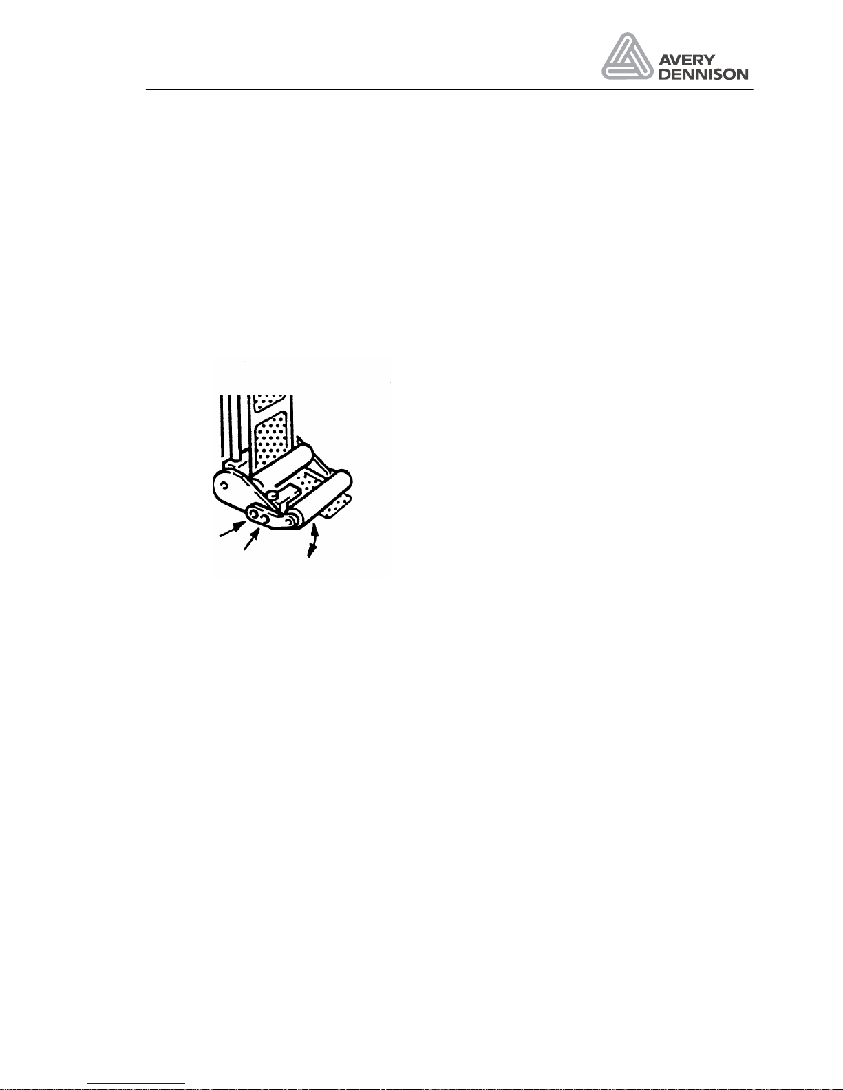
For some applications, it may be necessary to move the applicator roller relative to the
dispensing edge. To do this, loosen the two screws indicated in the diagram and pivot the roller
to the correct position before re-fastening the two screws.
Figure 7 Applicator roller
3.4 Changing the position of the dispensing edge
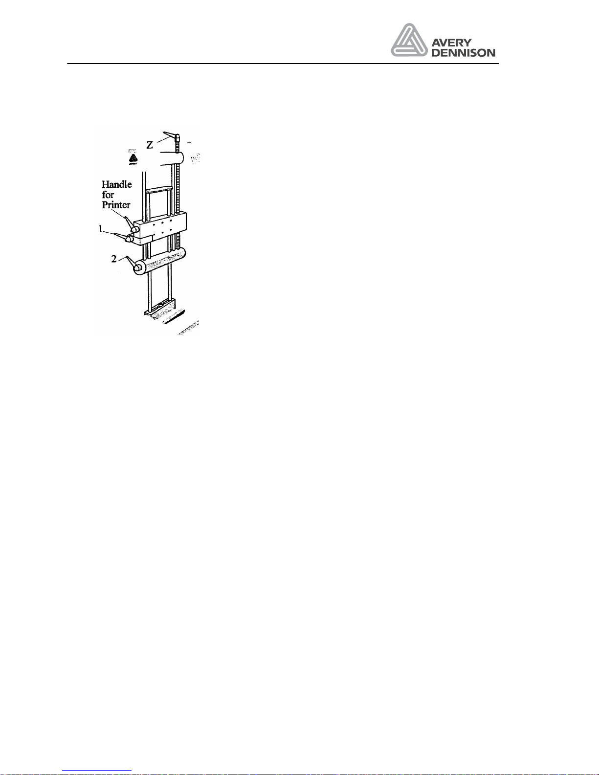
If your machine is equipped with a lead-screw adjustable dispensing edge, you may change the
position of the dispensing edge relative to the product. The lead-screw adjustable dispensing
edge allows adjustment towards or away from the product. The position can be read from the
scale on the dispensing arm bars.
Page 20
Operators Manual
ALS 341
Release 4/04 Page 16 Starting the labeller
Figure 8 Adjustable dispensing edge
Adjustment dispensing edge
After loosening handles 1 and 2, handle Z can be turned to adjust the dispensing edge position.
Once the adjustment is completed, tighten the handles 1 and 2 again.
Printer adjustment
If your labeller is equipped with a printer, you can adjust the print position as well with the
handle Z . In this case loosen the orange printer handle and handle 1 before turning handle Z .
Once the adjustment is complete, tighten the handles again.
3.5 Adjustment of the contrast
• Remove a label from the backing paper and slide it inside the sensor.
• Increase the value with the Contrast key until the LED switched on.
• Press the contrast key until the LED switched off. If there are marks on the backing paper
do the measurement on this position.
• Note the value GAP xxx
• Slide the backing paper including label inside the sensor. Use the lightest position on the
label for the adjustment.
• Reduce with the contrast key the value until LED lights again. Note the second value GAP
yyy
• Calculate the contrast value by the formula (xxx + yyy) / 2 and set it.
• The adjustment is completed.
With a difference of less than 6 an operation with this kind of sensor is not possible (sometimes
two or more labels are dispensed).
Page 21
Operators Manual
ALS 341
Release 4/04 Page 17 Starting the labeller
3.5.1 Capacitive label sensor
For transparent labels the standard photo label sensor doesn’t work. In this case, use a
mechanical or a capacitive label sensor.
For correct automatic initialisation, the contrast setting has to be set to any value, if you
using not the standard photo sensor.
A mechanical sensor is limited in the speed. The bounce at the label edges produces wrong
signals.
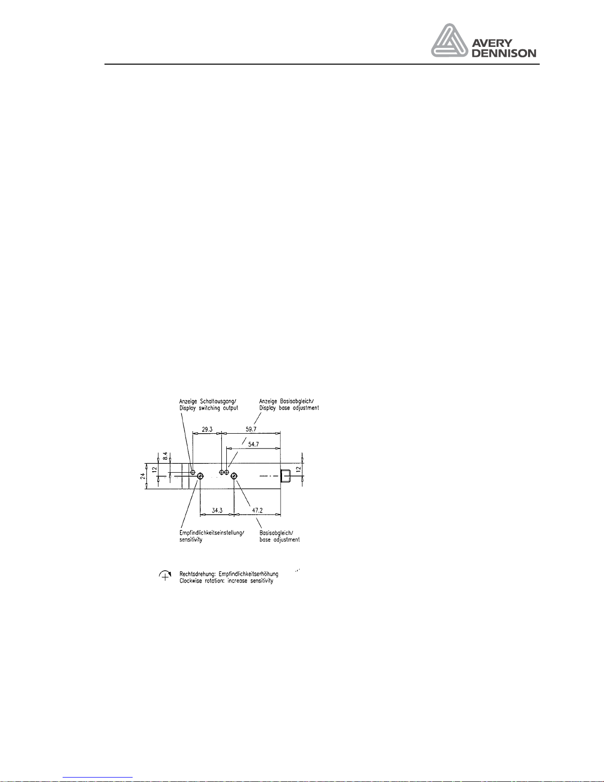
There is optional a capacitive label sensor available (Leuze GK14/24L).
Adjustment of the sensor is carried out as follows:
Set sensitivity to maximum by turning the Potentiometer clockwise. Then rotate ½ turn
anticlockwise.
1. Remove label material out of sensor.
2. Perform base adjustment, that both LED “base adjustment” have the same brightness.
3. Put label with backing paper inside the sensor. Doing this, the LED “switch output” and the
left LED “base adjustment” are switched off. With backing paper only in the sensor both
LED are switched on. If the LED are lightning with label inside the sensor, increase
sensitivity in ¼ turn steps by rotating the sensitivity clockwise.
4. Check the adjustment over the complete length of label.
5. Carry out the above adjustment after mounting, cleaning or increasing sensitivity.
Figure 9 Capacitive sensor
Page 22

Operators Manual
ALS 341
Release 4/04 Page 18 Starting the labeller
3.6 Label guide
On some of the axles, they’re guiding clamps. Adjust the clamps near the machine so all have
the same distance to the front plate (31.5mm). The outer clamps should be mounted that the
guide but not bend the label material.
With an L-dispensing edge, the adjustment is done by move the tail sheaves behind the
dispensing edge. Sometimes the front of the dispensing edge has a rot, which can be adjusted
for straighten the material guiding. Spend several labels by pressing the dispenser FEED key. If
the material guiding is running out of the guiding way, adjust the rot by loosing two screws at
the dispensing edge.
3.7 Adjust dispense function
For an operation without any trouble and high label accuracy, tree adjustments are required:
• Label position on the dispensing edge: stop position
• Dispense speed
• Label position on the product
The adjustment should be done in the same order, because parameter like the stop position
depends on the setting of the stop position and the dispensing speed.
3.7.1 Stop position
The first step is to adjust the stop position. This is the basic adjustment of the dispense
process. Also in case of problems with the machine check if the stop position is okay.
Figure 10 Stop position
The stop position should be adjusted so that the label stops at the dispensing edge up to 3 mm
behind.
The adjustment is done by moving the label sensor.
Page 23

Operators Manual
ALS 341
Release 4/04 Page 19 Starting the labeller
3.7.2 Labelling speed
Set Position to the distance between start sensor and dispensing edge. If installed remove the
roller to press the label onto the product. Now try to dispense one product. If the label has
wrinkles reduce the speed with the Speed down key. If the product peels out the label, so the
stop position of the next label is different to the last position increase the speed. Normally your
dispense speed should be a little bit higher than your product speed.
3.7.3 Label position on the product
At least adjust the position of the label on the product with the position keys.
Page 24
Operators Manual
ALS 341
Release 4/04 Page 20 Operation
4. Operation
The operator panel allows an easy operation of the machine. There are 4 functions to operate
the machine.
In the service menu, the service technician has the
possibility to configure the labeller according to your
application. This men menu is only for technician and
therefore protected.
4.1 Direct functions
The operator panel has a four-character display and 6 membrane keys. Each key has one
individual function.
Feed: Single start for one label.
Display: OKAY
Speed up: Higher dispensing speed
Speed down: Lower dispensing speed
Display: S020 until S550. The last digit is blinking to indicate the fractional
part of the number.
The message S020 means 2.0m/min and S550 means 55.0m/min.
Position Î: The label position on the product will be moved right.
Position Í: The label position on the product will be moved left.
Display: 0100 up to 9999. The last digit is blinking to indicate the fractional
part of the number.
The message 0100 means 10.0mm and 9999 means
999.9mm.
Attention: The start sensor should be positioned 10-30mm before the
dispensing edge.
Page 25

Operators Manual
ALS 341
Release 4/04 Page 21 Operation
Contrast: Setting the sensitivity of the label sensor.
Display: CX00 up to CX63. The X indicates the detection of label
material in the sensor.
4.2 Service menu
The service menu contains function to configure the machine and check functions.
4.2.1 Calling the menu
The service menu is protected by a password. The sequence to enter the password will be
started by pressing simultaneously both speed keys. CODE is shown on the display. The
password is entered by pressing these keys:
1 x Speed up key
2 x Speed down key
3 x Contrast key
If all is correct, P_S_ is shown in the display.
4.2.2 Working with the service menu
Select a function
By pressing the FEED key, all functions are visible in the display.
Call a function
The shown function is called by pressing the Contrast key. The current function setting is
shown.
Change function value
The setting will be changed by pressing the FEED key.
Back to select a function
Pressing the Contrast key returns to the level to select a function.
Close the service menu
If the Contrast key is pressed during the QUIT function the service menu is closed and the
software goes back to the direct functions.
Page 26

Operators Manual
ALS 341
Release 4/04 Page 22 Operation
4.2.3 Menu functions
The service menu contains these functions:
Polarity product sensor ___________________________________________ P_S_
This parameter inverts the switching logic of the product-sensor input. This can be used to
trigger the product sensor input on either the leading edge or trailing edge of the product.
TEDG = trailing edge detection
LEDG = leading edge detection
Note: The meaning of the LEDG and TEDG displays will be inverted if the product
sensor does not supply a positive going signal as it detects the leading edge of a
product.
Polarity label sensor ______________________________________________ S_S_
This parameter inverts the switching logic of the label sensor input. This can be used to trigger
the label sensor input on either the leading edge or trailing edge of the label.
TEDG = trailing edge detection
LEDG = leading edge detection
Note: Missing label compensation only works with label leading edge detection.
The meaning of the LEDG and TEDG displays will be inverted if the label sensor does not
supply a negative going signal as it detects the leading edge of a label.
Page 27
Operators Manual
ALS 341
Release 4/04 Page 23 Operation
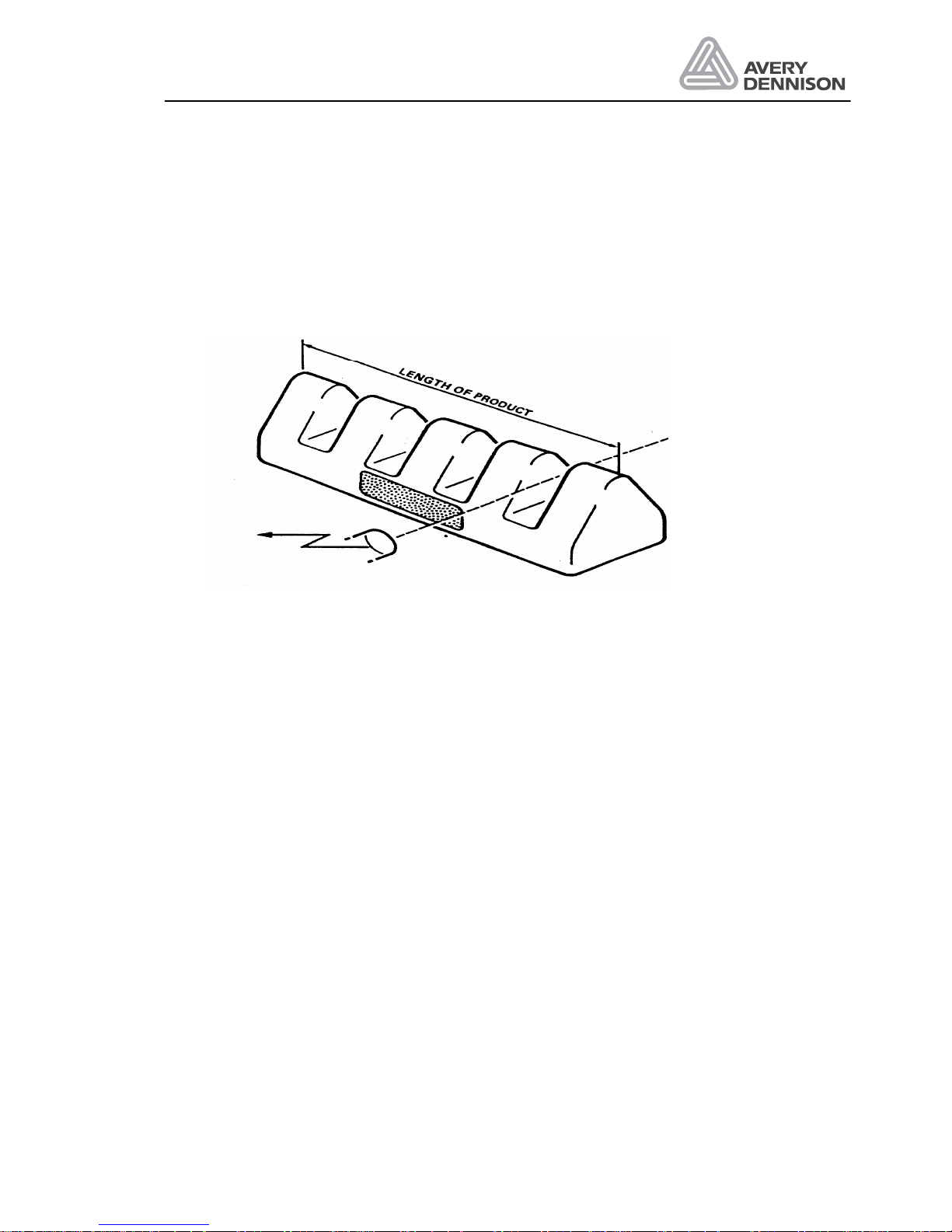
Product length ___________________________________________________PRDL
This parameter defines the length of the product to be labelled. After the product-sensor has
detected the edge of the product all further signals from the product-sensor are inhibited. This
parameter can be helpful in cases where the product is transparent or has several detection
marks or edges. Such a case is shown in the diagram below.
Figure 11 Example for product with multiple startsignals
The range for the "PRDL" parameter is from 5mm to 999mm.
Error message rewinder ___________________________________________ONF3
The error message F3 can be enabled (YES) or disabled (NO). The error message will be
generated, if the dancer arm of the rewinder is more than 3 seconds in the home position (web
brake).
Adjust loop control ______________________________________________ LOOP
With the loop function, you may change the operation of the loop control in accordance to the
label length you are using in the application. The factory value of 700 is an average value that
works well with the most of the applications. If you see a need for optimisation because of an
inconsistency in the loop the following rules apply:
1. A higher value makes the loop control running optimised smoothly and is recommend for
short labels.
2. A smaller value has to be used for running of long labels.
² input 1 connector CN5 pin 11/12 TBD
² input 2 connector CN5 pin 13/14 Material end sensor
² input 3 connector CN5 pin 15/16 OD - control
² input 4 connector CN5 pin 17/18 label inhibit input
Page 28

Operators Manual
ALS 341
Release 4/04 Page 24 Operation
Motor direction___________________________________________________ MDIR
This parameter is used to specify the running direction of the labeller's motors.
Possible values are "<---" and "--->" to suit a left-hand or right-hand machine respectively.
This parameter is already set at the factory.
Test run of labeller________________________________________________DTST
This parameter is used to test run all three motors of the labeller.
OFF The motor do not cycle.
STOP The loop motor, the dispense motor and the rewind motor cycle on and off.
ENDL The motor runs without any stop.
Note: If the loop photo sensor is blocked, then only the rewind motor will cycle.
Test of the labeller inputs __________________________________________ I_CH
This parameter is used to check the labeller inputs.
Product-sensor test
Press the FEED key to check the product sensor input.
The display format is: X--- or 0---
Note: As the product-sensor is triggered the first character of the display should
toggle between "X" and "0".
External control inputs
Press the /\ arrow key to check the external control inputs.
"0" indicates the input is not active
"X" indicates the input is active
Test of outputs__________________________________________________ O_CH
O_CH function enables you to check all outputs on connectors CN6 and CN10. The test shows
the current output state. For test you can toggle the current state. After function call the display
shows OUT? Leave the function by pressing ENTER.
CN6 are opto coupler outputs, while CN10 are 24V high side output drivers.
Page 29

Operators Manual
ALS 341
Release 4/04 Page 25 Operation
Test of the optocoupler outputs
Press FEED, Display shows XXXX
0 indicates that relevant output is not switched.
1 indicates that the output is active.
² CN6 pin 26/27 Ready output Press FEED for toggle
² CN6 pin 23/24 Warning output Press PRIOR for toggle
² CN6 pin 21/22 Error output Press NEXT for toggle
² CN6 pin 19/20 Printer output Press ENTER for toggle
You may jump back to O_CH menu by pressing all 6 keys together.
Test of the driver outputs
Press PRIOR, display shows LLLL
- indicates that the relevant output is not switched
+ indicates that the relevant output is switched on
L no load is connected to the output
K there is a short circuit (for example a broken wire) at the output
TEMP indicates an over temperature situation on the driver.
VOLT indicates that the supply voltage is too high
Each digit of the display toggles the representative output, when you press the
corresponding panel key:
² CN10 pin 9/10 Printer FEED for toggle
² CN10 pin 7/8 Pneum. dispensing edge PRIOR for toggle
² CN10 pin 5/6 Motor run signal NEXT for toggle
² CN10 pin 3 /4 ODC output ENTER for toggle
You may jump back to O_CH menu by pressing all 6 keys together.
Rewind check___________________________________________________ RWCH
According to the position of the rewind dancer arm a varying signal level is received at the
labellers rewind dancer arm input. This value can be displayed with the RWCH parameter.
When the dancer arm is in the home position the display should show zero. When the dancer
arm is in its end position (extended) the display should read between 220 and 240. If this is not
the case then the rewind internally mounted rewind coder disk and rewind adjustment
potentiometer should be adjusted as described in the chapter "Servicing the labeller".
Page 30

Operators Manual
ALS 341
Release 4/04 Page 26 Operation
Label count_____________________________________________________ LABC
This parameter is used to show how many labels have been dispensed by the labeller since
installation.
The number of labels dispensed is displayed in the format:
Mnnn Knnn .nnn
where M represents millions
K represents thousands
.represents units
On entering the "LABC" parameter the units are displayed. By using the arrow keys can then
be used to change between the millions, thousands and units displays.
Leave configuration_______________________________________________ QUIT
This menu point is used to go back to the direct functions.
Page 31

Operators Manual
ALS 341
Release 4/04 Page 27 Messages and Troubleshooting
5. Messages and Troubleshooting
The control checks continuously the status of the machine. If something goes wrong, relevant
messages are displayed and simultaneously an output signal is supplied. This output signal can
be used as a control signal to an external control.
5.1 Warnings
If the labeller control distinguishes a situation, which is not in order, however, the labeller
continuous to work, a warning message is displayed: e.g. WA_2.
WA 1 Hardware fault
The data are set to the default value.
• All settings have to be entered again.
• Use the table below to note your setting
• If the warning is indicated more frequently, you should call for service, to get the battery on
the CPU board exchanged.
Function Default value Note your setting
MDIR Î
LABC 0
P__S LEDG
S__S LEDG
ONF3 ON
LOOP 700
Speed 30.0 m/min
Position 10,0 mm
CONT 56
PRDL 5 mm
WA 2 OD control
The label material is nearly at the end. This indication need that the optional OD control is
installed.
Page 32

Operators Manual
ALS 341
Release 4/04 Page 28 Messages and Troubleshooting
5.2 Error messages
For most of these errors, the labeller can not operate until the cause of the error is removed.
The labeller stops operating and a signal is supplied at the error output. You may restart the
labeller by pressing the ENTER key once you have cleared the error situation. The ready
output goes off.
Message Description How to solve
F1 Loop will not be filled loop sensor not
activated
Normal if end of material else
• pressure roller not closed
• check function of loop sensor
• clean mirror
• readjust potentiometer of loop
sensor
• unwind motor is not running
F2 Labeller doesn’t detect the start of a
new label
Normal message at
• End of label material
• More than 3 missing label on the
web
else check
• pressure roller not closed
• label web is not correctly
threaded through the label sensor
• Label did not start from the
correct start position
• while the label sticks to the
product, it pulls the backing
material may be because of
different dispense and product
speeds
• Label length is shorter than label
pitch entered
• Wrong adjustment of label sensor
CONT
• Loop empty
• drive motor is not running
F3 Indicates a problem with the rewind
function.
End of material or label web broken
Check if rewind motor is running at all
E_15 Short circuit or fault condition on of the
outputs of CN10.
Check the connections on the
outputs. Call the function O_CH to
get more information.
If the problem reoccurs and in all other cases you need to call your Service Technician.
Page 33

Operators Manual
ALS 341
Release 4/04 Page 29 Messages and Troubleshooting
5.2.1 Processor error
If the processor detect an illegal condition one of the following error messages will be
displayed. The machine stops immediately. The ready output is switched off.
ER-U An undefined interrupt was requested.
ER-I Illegal processor instruction.
ER-D Division error.
ER-T Undefined software interrupt.
ER-A Address error.
If one of these errors appears, press the ENTER key and note the displayed information. Note
also the used software version you can see on power on the machine, what happened before
the error occurs and contact your Service Technician.
5.3 Trouble shooting
If your machine doesn’t work call your Service Technician. The following trouble shooting table
is only for experienced user.
Problem How to find it How to solve it
No machine function Lamp in main switch doesn’t
light
Replace fuses located on screw
terminal. Check power connections
for damaged wires
One of the stepper motor
doesn’t work
Green LED of stepper motor
driver doesn’t light or red
LED lights
Check motor supply voltage not >
110V AC
Replace driver
Don’t repair the stepper motor
driver!
No 24 Volt supply Green LED on rectifier board
not lightning
Fans not running
LED D2 on CPU board not
lightning
Check fuse on rectifier board
No display LED D4 on CPU board not
lightning
Check fuse F2 on CPU board
LED D3 on CPU board not
lightning
LED on sensor not lightning
Check fuse F1 on CPU board Wenglor label sensor
doesn’t work
LED on sensor okay but
label doesn’t stop
Check jumper JP3 inserted
Page 34

Page 35
Operators Manual
ALS 341
Release 4/04 Page 31 Electrical connections
6. Electrical connections
WARNING! - The machine is connected to mains.
y Only authorised personnel may open the cover.
y Disconnect from the mains before opening the covers.
y Operation without cover is not allowed.
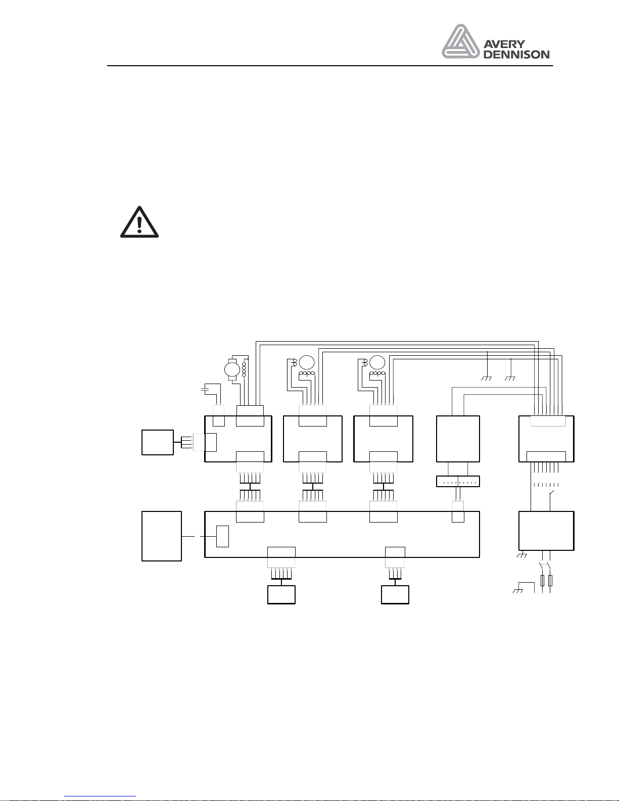
6.1 Power supply
Select the line voltage on the transformer so that the voltage for the stepper motor driver not
exceeds 110 VAC.
CN20
Displ ay
Key pad
8771.1 1
8566.0 1
CN1
CN2
CN3CN4
CN1
CN1
8578.0 2
Step permotor control
Step permotor control
CN1
CN1
8578 .02
REWIND
SEN SO R
1
2
12345
6
1
2
3
4
12345
6
12345
6
Maind rive
Steppermot or
Rewind
AC Motor
MP Capaci t or
4uF/ 450V
12345
6
12345
6
Loop
Steppermotor
AC motor control
736.2 8
67.4 4
5550.0 2 5550.02
swgegn
or+ws/sw
sw+ws/or
rt+ws/ge
ge+ws/r t
ge+ws/r t
or+ws/sw
sw+ws/or
rt+ws/ge
345678
8567.0 1
CN22CN19
CN18CN17CN16 CN1
12345
6
12345
6
12345
6
12345
6
123
4
1
2
CPU - boar d
Recti f ier
8577.0 2
+-
sw = black
ge = yellow
gn = gr een
ws = whit e
rt = red
or = orange
SEN SO R
STOP -
SEN SO R
LOOP-
Trans f or mer
1234567
8
779.0 5
GECD
6.3A
Linevoltage
Linefilter
AB F H
NL1
NL1
100V
120V
130V
200V
220V
230V
240V
Figure 12 Line supply
Page 36
Operators Manual
ALS 341
Release 4/04 Page 32 Electrical connections
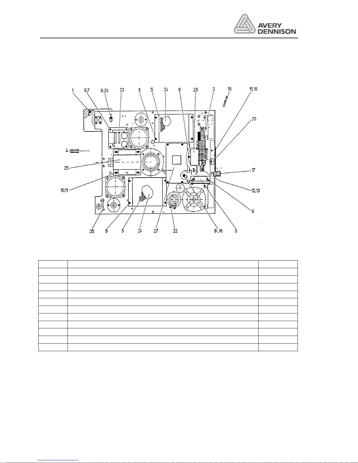
6.2 Location of the electronic control boards
Figure 13 Electrical components
Position Description Order no.
1 Operator Panel 0008576-01
2 Mains screw terminal 0009305-01
3 AC-motor control board for rewind motor 0008566-01
20 Main switch 0001510-05
22 Rewind sensor 0008257-01
23 24 V rectifier board 0008577-02
24 Stepper motor control boards 0008578-04
25 Transformer 0000779-05
26 Mains interference filter 0006009-01
27 CPU control board 0008567-01
35 Label sensor 0005082-06
Page 37
Operators Manual
ALS 341
Release 4/04 Page 33 Electrical connections
6.3 Stepper motor control
5,6A
200 Schr
Voltage fault
+ Clock
+ Direction
- Direction
- Boost
+ Boost
- Clock
Ready
110V AC
110V AC
Phase1
Phase1
Phase2
Phase2
Ready Emitter
4A
Jumper for current selection
Jumper for resolution
LED
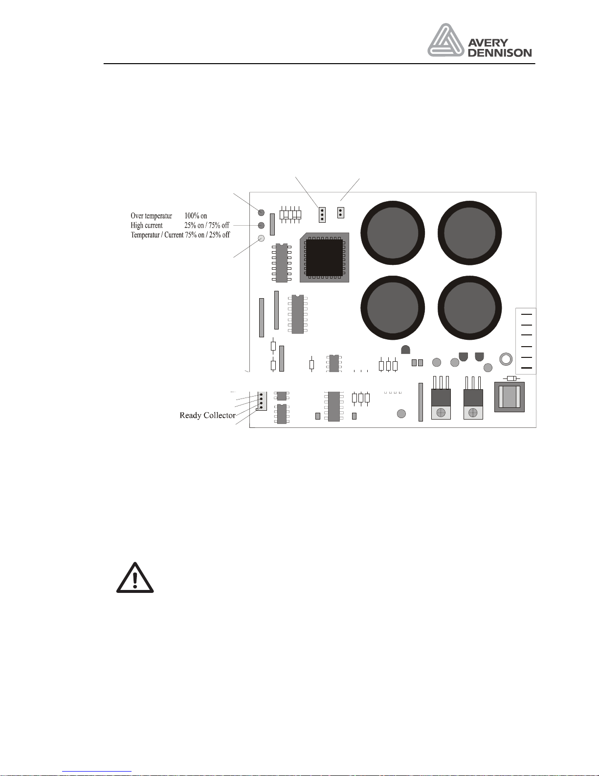
Figure 14 Stepper motor control
Jumper for current level setting normally set towards the centre of the board for 5.6 A.
To reduce heat, the current for the loop motor could be set to 4A for small labels and low
production rate.
The jumper for the stepper resolution is open.
For connection with an old 6 pole cable, plug in the connector that the ready output is not used.
WARNING! - The electronic is driven by high voltage.
y Don’t touch the board if the machine is switched on.
y The operation of the board is only allowed with connected motor.
y Don’t handle any connector or jumper during operation.
y It is strictly prohibited to do any modification or repair onto the board.
Especially the fuse should not replaced and the pot should not be
disadjusted.
Jumper for current setting
Page 38
Operators Manual
ALS 341
Release 4/04 Page 34 Electrical connections
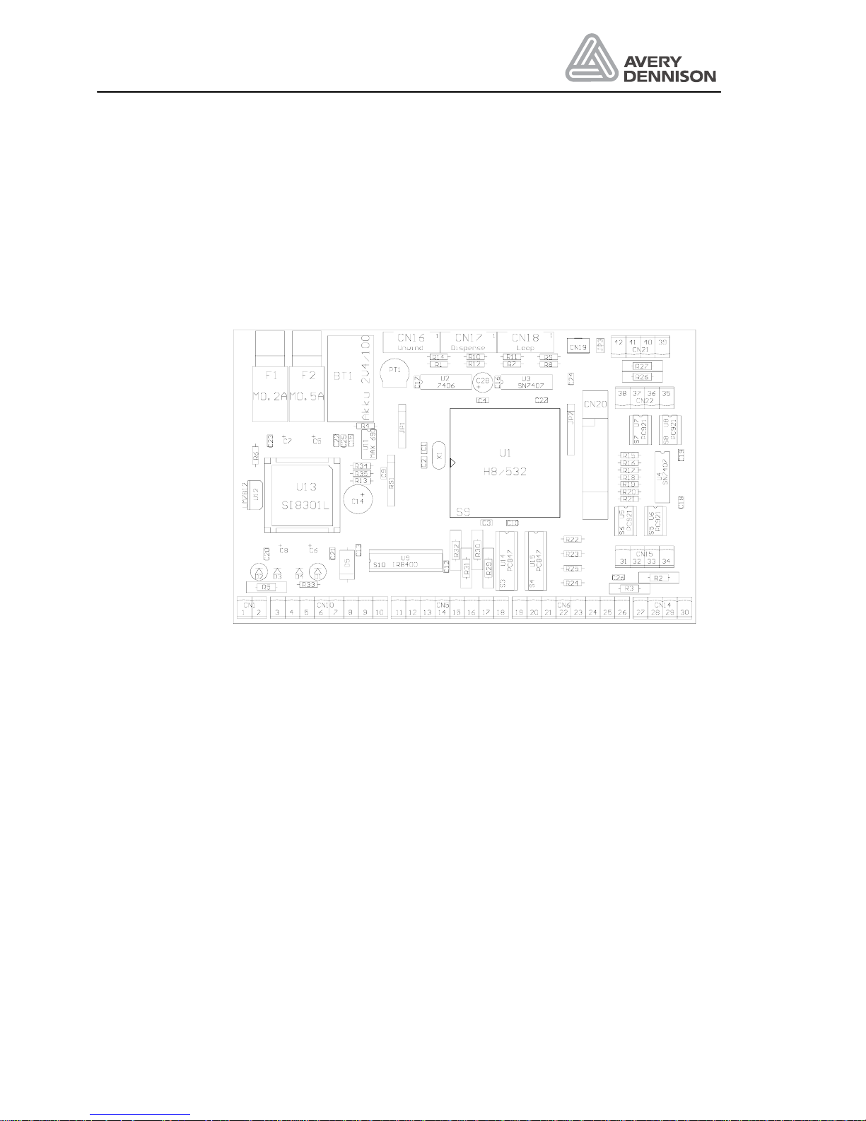
6.4 CPU - board
The LED’s of CPU-board indicated the following functions:
D1 error output active (only valid if a minimum load of 10kΩ on all outputs of CN10)
D2 24 V in order
D3 12V in order
D4 5V in order
Figure 15 Layout CPU board
Plug connector (in- and output ports)
CN 1 24 V supply voltage
CN 5 Opto coupler inputs
CN 6 Opto coupler outputs
CN 10 PNP output driver
CN 14, 15, 22: Opto coupler sensor inputs
CN 19 or 21: Label sensor alternatively you may use one of the 2 plugs for connecting
a label sensor. If standard label sensor is in use, jumper J3 must be fitted,
in order to have 12 V supply voltage available. Other label sensor must be
connected to CN 21 and J3 taken off, to ensure 24 V supply voltage.
Page 39
Operators Manual
ALS 341
Release 4/04 Page 35 Electrical connections
IN+
1
IN-
2
NC
3
NC
4
VCC
8
GND
7
OUT
6
VH
5
PC921
1k
VCC
VCC
GND
JP3
+12V
1
2
3
4
5
5..20mA
CN19
+12V
GND
Figure 16 Label sensor
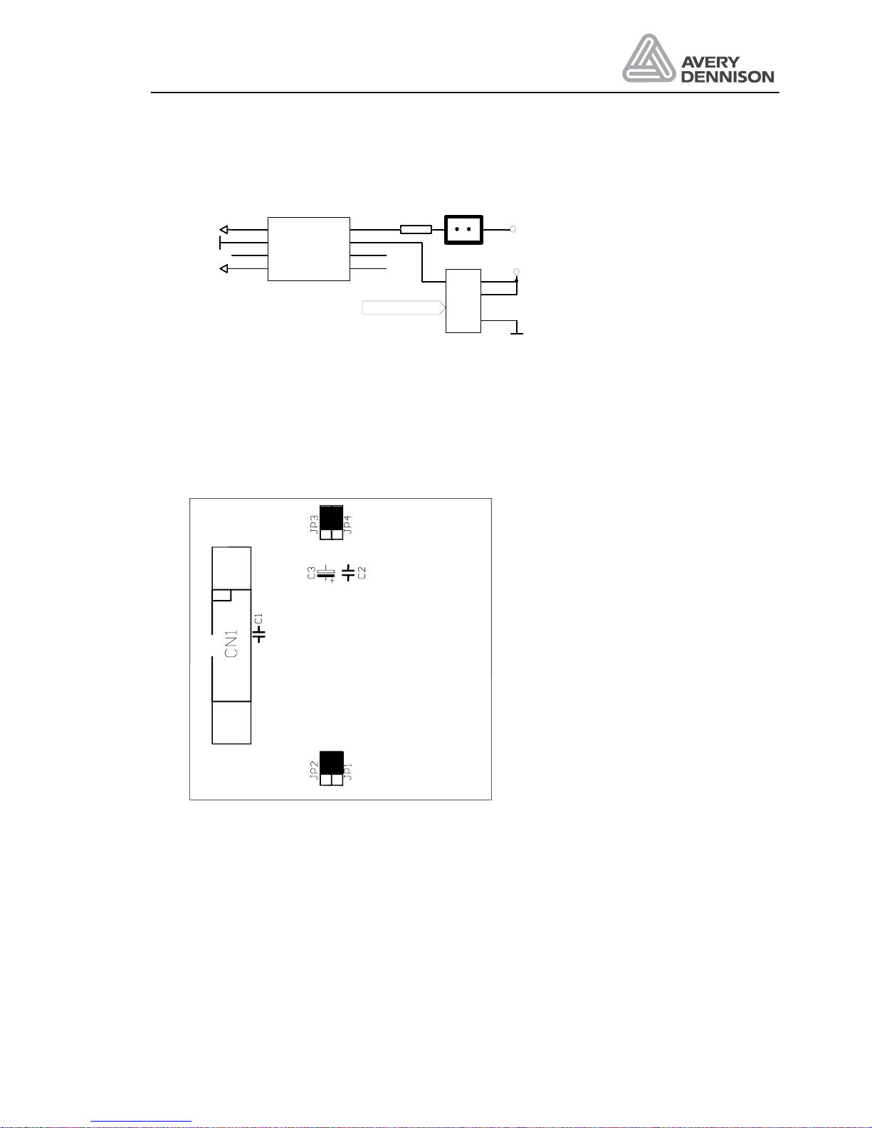
6.5 Display
All jumpers have to be in the upper position.
Page 40
Operators Manual
ALS 341
Release 4/04 Page 36 Electrical connections
6.6 Description of I/O signals
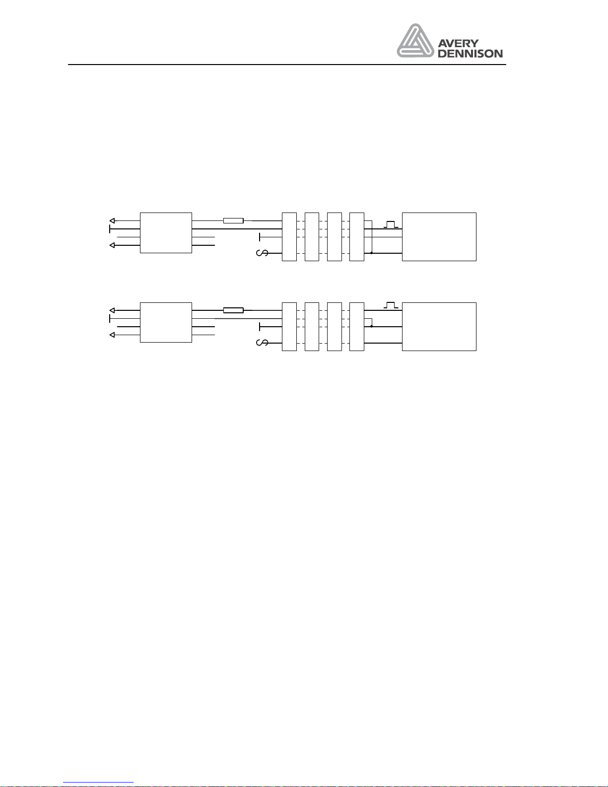
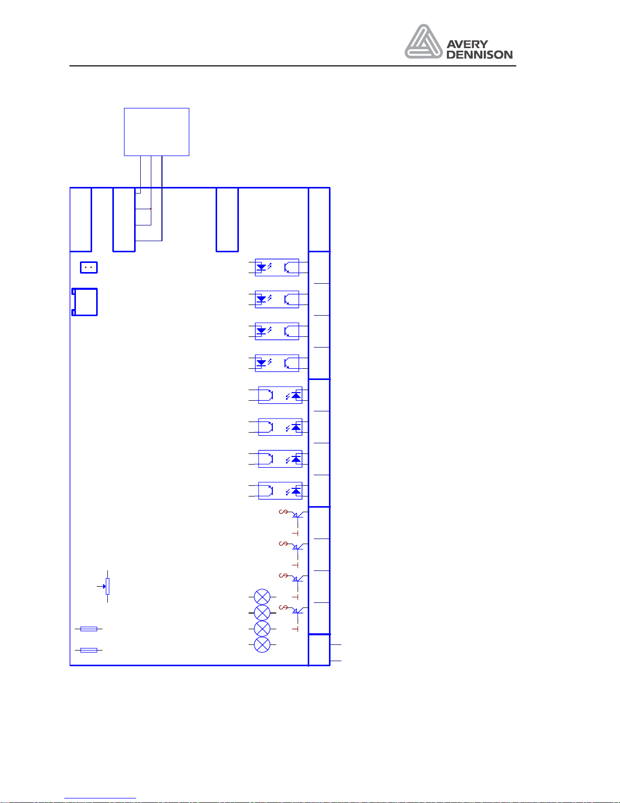
The external I/O signals are connect to the terminal on the CPU board Figure 18.
All input are electrically separated by opto couplers. NPN and PNP sensor output can be
connected shown in Figure 17.
CN14
IN+
1
IN-
2
NC
3
NC
4
VCC
8
GND
7
OUT
6
VH
5
PC92 1
CC
CC
1k
+24V
GND
27
28
29
30
IN+
1
IN-
2
NC
3
NC
4
VCC
8
GND
7
OUT
6
VH
5
PC92 1
CC
CC
1k
+24V
GND
31
32
33
34
35
36
37
38
39
40
41
42
CN15
CN21
CN22
27
28
29
30
31
32
33
34
35
36
37
38
39
40
41
42
24V NPN- Senso
24V PNP-Senso
r
+24V
+24V
ND
ND
Figure 17 Sensor connection
There are two type of output
• Opto coupler driving up to 50mA
• High side driver PNP type outputs supplying up to 1A.
Ready This output is on, if the labeller is powered on, the condition is online and
no error is active.
Warning The function of the output depends on the selected modes in the
configuration:
Tandem mode off: This output is on if any warning condition is meet.
Tandem mode on: Output for tandem operation
Error This output is turned on, if a error condition exist.
Printer (CN6) This output is switched on every time a label is dispensed. The active time
is 50ms.
Inhibit If this input is active, a signal from the product sensor will be ignored.
OD-input If this input is active, a warning will be displayed and the OD-output
switched on.
Printer (CN10) Print signal like the printer output.
Page 41

Operators Manual
ALS 341
Release 4/04 Page 37 Electrical connections
Pneumatic-Edge This signal is active, if a label is dispensed.
Motor run The signal is active if the dispense motor is running.
OD-output The output is active, if the OD-input is active.
Page 42
Operators Manual
ALS 341
Release 4/04 Page 38 Electrical connections
Figure 18 I/O Terminal
D2
24V
D3
12V
D4
5V
D1
Outputerror
F1
M0. 2A
F2
M0. 5A
P1
Rew indspeed
CPU - Board
123456789101112131415161718192021222324252627282930
CN1
-+
24V
OD-control out
Ausgang OD Kontrolle
++++CN10
Motorlaufsignal
Motorrun output
Pneumatische Spendekant
e
Pneumatiic dispensing edg
e
Printeroutput (*)
Druckerausgang (*)
GND
GND
GND
GND
+24V
+24V
+24V
+24V
Fehler löschen (*)
Clear error (*)
Materialende
Material end
Printerou tpu t
Druckerausgang
OD-control in (*)
Eingang OD Kontrolle (*)
inhibit
Startunterdrückung
CN5 CN6 CN14
Fehlerausgang
Erroroutput
Warningoutput (*)
Warnausgang (*)
Ready
betriebsbereit
Productsensor
Produktstart
15V
5V
CN15
31 32 33 34
Speedsensor
Geschwindig-
keitssensor
CN21
CN22
35363738
39404142
Loopsensor
Schlaufensenor
Stopsensor
1
2
3
4
5
Stopsensor
JP3
bl
rd/bl
wh/br
CN19
(*) The function depend s on selected mod e
(*) Die Funktion wird durch di e e i ngestellte Betriebsart bes timmt
Page 43
Operators Manual
ALS 341
Release 4/04 Page 39 Electrical connections
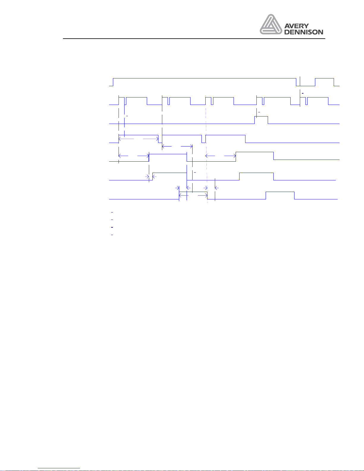
Productstart
Dispense
Dispensing edge
Output CN10 / 8
POS
Product Output
PRDL
APOS
CN10 / 6
CN6 / 19
Printer Output
CN10 / 10
PDT
Ready
Inhibit
PDWT
POS
POS
1
2
4
1
2
3
Missing Label: New start of dispense during printer activ
Inhibit activ
Machine not ready. Errorcondition or not online
3
4
Productstart disabled. PRDL activ
PHT
Figure 19 Timing diagram
6.7 EMI
To protect the machines against electrical noise and to protect production of electrical noise
you have to follow these rules:
Rule 1
All metallic parts must have a good and plane contact (no lacquer, aluminium oxide is an
isolator). Use scratch washers.
Rule 2
A signal line (Data-, communication- and control cable) has to separate to power cables. The
minimum distance is 50 cm (20 cm inside a cabinet).
Rule 3
All signal lines should be lead in the machine or cabinet only on one side.
Rule 4
Unshielded cables must be twisted (both poles).
Page 44

Operators Manual
ALS 341
Release 4/04 Page 40 Electrical connections
Rule 5
On all inductive components (relays, valves) must be directly connected a clamp circuit (diode,
MOV).
Rule 6
All signal lines must be shielded. The shield must have a good earth connection on both
sides.
For the connection use metallic clamps. Don’t use a soldered wire for this connection.
In case of different earth potential on both cable sides install parallel a cable of at minimum 10
mm
2
.
Rule 7
The shield of analogue cable (Video etc) should be shielded only on one side. Normally there
are no such cables with labelling machines.
Rule 8
Line filter has to be mounted directly on the cable entry.
Rule 9
Cables should not fly in the air. Lead all cables nearby metallic, grounded parts. Ground
unused cables and wires in a cable at minimum on one side, better on both.
Rule 10
Cables should not be longer as necessary.
Page 45

Operators Manual
ALS 341
Release 4/04 Page 41 Maintenance
7. Maintenance
The labeller has a minimum of movable parts, which ensures a minimum of maintenance
required.
7.1 Cleaning
A weekly check of the following is recommended:
1. Clean all rollers from glue and labels. Use a solvent or alcohol
2. Use a soft brush for cleaning all photocells (loop sensor, label sensor and product sensor).
3. Clean the dispensing edge of adhesive residue and paper dust with alcohol or solvent.
4. Clean paper brake brush and plate to ensure even tension. Use solvent or alcohol.
5. Reverse paper brush if brush is pretended.
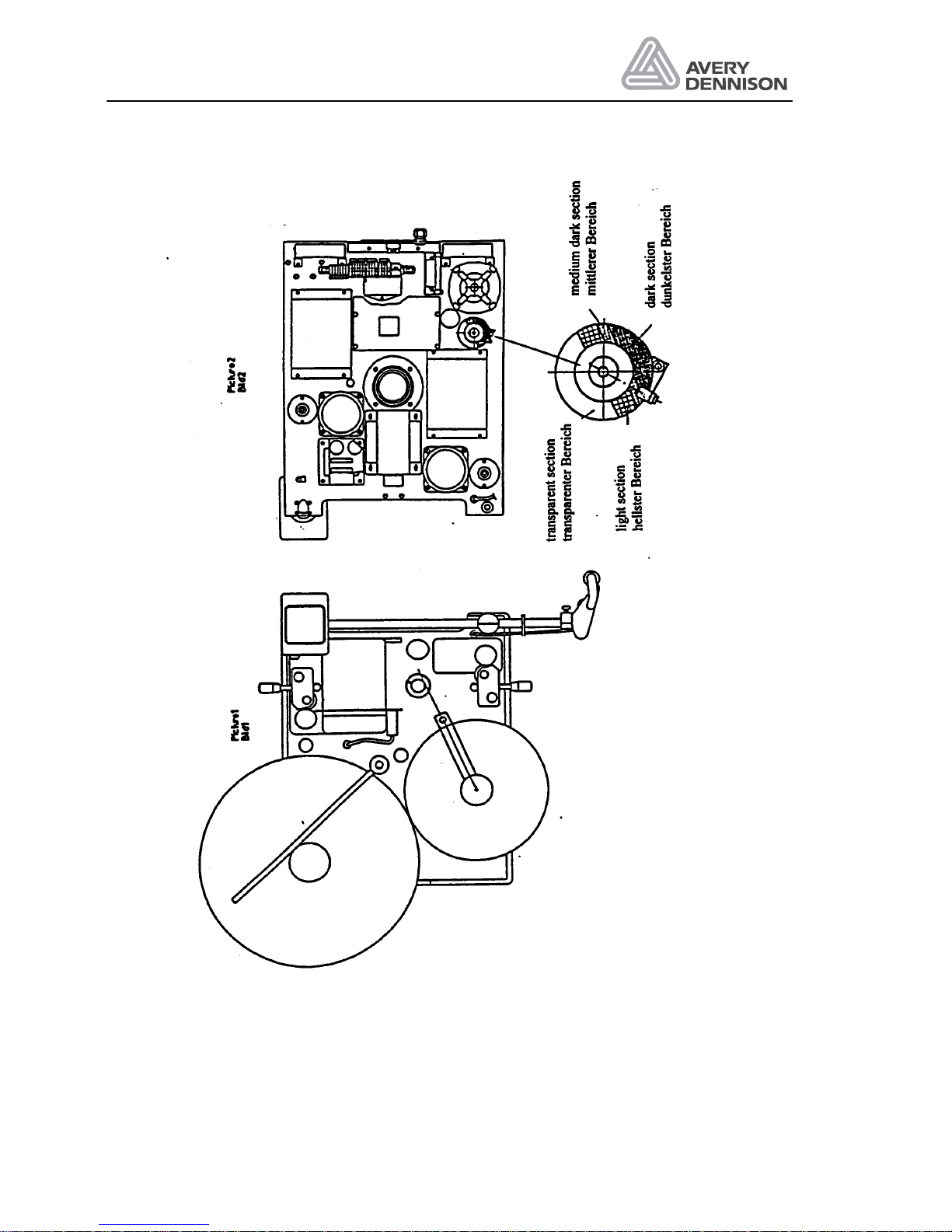
7.2 Adjustment of rewind function
For the rewind control only a combined adjustment of mechanics and electronic is necessary.
Function of the rewind: The speed of the rewind is controlled via a sensor that supplies signals
to the CPU-board. The CPU-board supplies control signals to the AC motor system. A dancer
arm driven coder disk with light and dark segments moves through the rewind sensor.
Depending on the amount of light the rewind sensor receives, a proportional signal is supplied
to the CPU-board.
1. Move the dancer arm in position as shown in Figure 20 picture 1.
2. Rotate coder disk according to Figure 20 picture 2(unscrew the two screws before rotating
and fasten in drawn position.
3. Move dancer arm to max loop position.
4. Adjust by means of the potentiometer P1 the speed of the rewind mandrel to a maximum
speed of 55m/min (380 = 100m/min). If the average speed of your application is lower, for
optimised smooth operation adjust accordingly. If error E_04 appears on the display value
between 200 to 250.
5. You may check the proper function of the rewind sensor under function RWCH in the
configuration menu. Dancer arm in min position display value 0000. Dancer arm position
between min and max position are producing values between 0 and 200, depending on
which section of the coder disk is in the rewind sensor.
Potentiometer P1
The potentiometer P1 is located on the CPU board. By means of P1 you adjust the rewind
speed.
Page 46
Operators Manual
ALS 341
Release 4/04 Page 42 Maintenance
Figure 20 Rewind adjustment
Page 47

Operators Manual
ALS 341
Release 4/04 Page 43 Technical Specification
8. Technical Specification
Label width ( incl. backing paper) 10 - 1552 mm
Label length Min. 16 mm, max. 250 mm at max speed,
350 mm at lower label rates per minute rate –
average speed should not exceed 50% of
labelling speed.
Label unwind outside diameter max. 400 mm
Label unwind inside diameter 76.2 mm
Backing paper rewind collapse driven
Label stop accuracy at dispensing edge +/- 0.5 mm
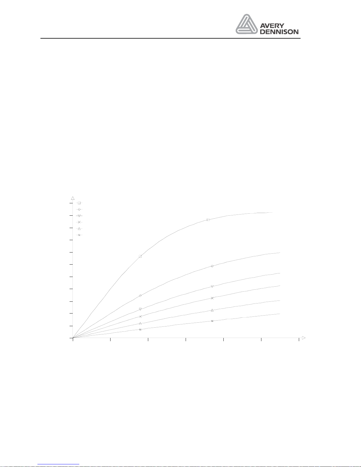
Label cycles/minute see charts
Drive system IP41: 2 stepper and 1 AC motors
IP54: 3 stepper motors
Labelling speed up to 55 m/min
Electronics integrated
Label sensor IR-fork sensor
Minimum distance between label sensor
and dispensing edge
10 mm
Control functions and diagnostic adjustable via operators panel
Mechanical execution right or left hand
Dispensing edge L form
Side plate 15 mm plate aluminium anodised
Rear cover PUR material
Dimensions (W*H*D mm ) 735*795*400
Weight 70 kg
Protection class IP 41 / IP 54 optional
Operating environment 5 – 40°C, storage 0 – 70°C
30 - 80%, non condensing
Power consumption 500 VA
Mains voltage 110 / 120 / 130 / 200 / 220 / 230 / 240 VAC
50 /60 Hz
Page 48
Operators Manual
ALS 341
Release 4/04 Page 44 Technical Specification
8.1 Application specification
The labeller is designed and built for automatic applying of self-adhesive labels.
8.2 Advice for security
In order to avoid any risk of injury due to squeezing between the fixed dispensing edge and the
passing product, it may be necessary to add a protection cover in front of the dispensing edge.
The necessity for this has to be decided on case by case.
8.3 Performance
0 10 20 30 40 50 60 m/min
labels/min
0
100
200
300
400
500
600
700
800
900
1000
1100 25 mm
50 mm
75 mm
100 mm
150 mm
250 mm
Figure 21 Labelling rate
Page 49

Operators Manual
ALS 341
Release 4/04 Page 45 Index
9. Index
C
capacitve label 16
D
DTST 23
L
LABC 25
Label length 27
label sensor 14, 21, 32, 39, 41
Labelling speed 41
M
MDIR See Motor direction
Motor direction 23
P
P_S_ See Product sensor polarity
PRDL See Product length
Printer 15, 24, 34
Product length 22
Product sensor 21, 23, 34, 39
Polarity 21
T
Threading 12, 13
Page 50

10. CE Declarations
Page 51
KONFORMITÄTSERKLÄRUNG
AVERY Maschinen GmbH
Ohmstraße 3
85385 Eching
Wir erklären in alleiniger Verantwortung, daß das Produkt
Produktart: Etikettiermaschine
Maschinenbezeichnung: Etikettenspender
Maschinentyp: ALS 341
Seriennummer: 09250-0x-xxxx
mit den folgenden Normen und normativen Dokumenten übereinstimmt
y 89/392/EWG Maschinenrichtlinie
geändert durch: 91/368/EWG; 93/44/EWG; 93/68/EWG
Hierfür wurden nachstehende harmonisierte Normen angewandt
y EN 60204 Teil 1 (VDE 0113) Niederspannungsrichtlinie
y EN 292 Teil 1 und 2 Sicherheit von Maschinen
y EN 294 Sicherheitsabstände
y EN 418 Sicherheit von Maschinen
y EN 50081-1 und EN 50082-2 Störfestigkeit
Hinweis und Einschränkung für diese Erklärung:
Diese Konformitätserklärung gilt nur für diese Etikettiermaschine und nicht für Maschinen im Umfeld oder in Kombination mit
dem Etikettierer. Ist die Etikettiermaschine Bestandteil einer größeren Maschineneinheit, also darin integriert, muß der
Hersteller der gesamten Maschineneinheit eine Konformitätserklärung für diese Maschineneinheit ausstellen. Aus der
Tatsache, daß diese Maschine CE gekennzeichnet ist, kann nicht abgeleitet werden, daß eine CE-Konformität der gesamten
Maschineneinheit gegeben ist. Besondere Beachtung sollten in diesem Zusammenhang die oben aufgeführten Richtlinien,
Normen und Spezifikationen (ohne Anspruch auf Vollständigkeit) finden. Diese Konformitätserklärung verliert ihre Gültigkeit,
wenn bauliche Veränderungen vorgenommen werden, die nicht vom Hersteller durchgeführt wurden.
Eching, 13. Mai 2003
Ferdinand Pranckh
(Werksleitung)
Page 52
DECLARATION OF CONFORMITY
AVERY Maschinen GmbH
Ohmstr. 3
85385 Eching
We declare under our exclusive responsibility that the product
Product: Labelling machine
Type of product: Labeller
Machine name: ALS 341
Serial number: 09250-0x-xxxx
is in conformity with the following standards:
y 89/392/EWG Machinery directive
changed by: 91/368/EWG; 93/44/EWG; 93/68/EWG
and the below mentioned documents have been applied:
y EN 60204 Part1 (VDE 0113) Low voltage regulation
y EN 292 Part 1 and 2 Safety requirements
y EN 294 Save headway
y EN 418 Safety
y EN 50081-1 and EN 50082–2 Generic immunity standard
Comments and restriction for this declaration:
This declaration of conformity is valid only for this labelling machine and not for the machines used or installed in combination
with or associated with the labeller.
If the machine is part of a larger machine system, i.e. integrated into a machine system, the manufacturer of the complete
machine system must make a declaration of conformity for the complete system.
Attention should be paid to the specifications, rules and standards as given above in addition to the preceding declarations
This declaration of conformity is no longer valid, if any changes are made to the machine which are not under the control of
and agreed upon, with the manufacture of the machine.
Eching, 13.5.2003
Ferdinand Pranckh
(Plant manager)
Page 53
DECLARATION DE CONFORMITE
AVERY Maschinen GmbH
Ohmstraße 3
85385 Eching
Nous déclarons sous notre seule responsabilité que le produit
Produit: Machine d'étiquetage
Type de produit: Etiqueteuse
Nom de la machine: ALS 341
No. de série: 09250-0x-xxxx
est en conformité avec les normes suivantes:
y 89/392/EWG Directives machinerie
révision: 91/368/EWG; 93/44/EWG; 93/68/EWG
et que les documents mentionnés ci-dessous ont été considérés:
y EN 60204 Partie1 (VDE 0113) : Réglage basse tension
y EN 292 Parties 1 et 2 :Normes de sécurité Principes de Conception
y EN 294 : Distances de protection des membres supérieurs
y EN 418 : Sécurité.
y EN 50081-1 et EN 50082-2 : Directive générale Immunité.
Remarques et restrictions à cette déclaration
Cette déclaration de conformité est valide seulement pour la machine mentionnée ci-dessous et non pour les machines
utilisées ou installées en combinaison ou associées à cette machine.
Si la machine fait partie d'un ensemble, c'est-à-dire est intégrée dans une machine complète, le fabricant de cette machine
doit établir une déclaration de conformité pour cet ensemble complet. L'attention doit être portée aux spécifications, règles et
normes mentionnées ci-dessus en addition à la présente déclaration.
Cette déclaration de conformité devient caduque si une quelconque modification a été apportée à cette machine sans le
contrôle et l'agrément du producteur.
Eching, 13.5.2003
Ferdinand Pranckh
(Directeur d´usine)
Page 54
CONFORMITEITSVERKLARING
AVERY Maschinen GmbH
Ohmstr. 3
85385 Eching
Wij verklaren onder onze uitsluitende verantwoordelijkheid dat het produkt
Produkt: Etiketteermachine
Type produkt: Etiketteerkop
Naam machine: ALS 341
Serienummer: 09250-0x-xxxx
Conform is met de volgende standaards:
y 89/392/EWG Machinerichtlijn
gewijzigd door: 91/368/EWG; 93/44/EWG; 93/68/EWG
De hierna genoemde documenten zijn in aanmerking genomen:
y EN 60204 Part1 (VDE 0113) Low voltage regulation
y EN 292 Part 1 and 2 Safety requirements
y EN 294 Save headway
y EN 418 Safety
y EN 50081-1 and EN 50082–2 Generic immunity standard
Opmerkingen en beperkingen :
Deze conformiteitsverklaring geldt uitsluitend voor de ALS330 en niet voor machines die in combinatie met de ALS 341
worden gebruikt of geinstalleerd, of eraan worden gekoppeld. Indien de ALS 341 deel uitmaakt van een groter
machinesysteem, i.e. geintegreerd is in het machinesysteem, moet de fabrikant van dit volledige machinesysteem een
conformiteitsverklaring afleggen voor het gehele systeem.
In dit verband moet bijzondere aandacht worden besteed aan de vermelde richtlijnen, normen en specificaties (zonder
aanspraak op volledigheid). Deze conformiteitsverklaring verliest haar geldigheid indien wijzigingen worden aangebracht aan
de ALS 341 die niet gecontroleerd of toegelaten zijn door de producent.
Eching, 13.5.2003
Ferdinand Pranckh
(General Manager)
 Loading...